

Page 1

Cisco NCS 1001 Overview
This chapter provides an overview of Cisco NCS 1001.
Cisco NCS 1001 Overview, page 1
•
Optical Amplifier Module, page 5
•
Protection Switching Module, page 6
•
Product IDs, page 7
•
LEDs in Cisco NCS 1001, page 8
•
Cisco NCS 1001 Overview
Cisco NCS 1001 (NCS1001-K9) is 1 RU chassis that addresses the growing bandwidth needs of data center
DWDM applications. It provides a DWDM line system that is optimized for data center environments and is
optimized for point-to-point applications at maximum capacity. NCS 1001 supports up to three optical modules.
The modules can be amplifiers or protection switching modules.
NCS 1001 has the following components:
Removable control card
•
Four removable fans
•
Two removable 600W AC/DC or DC/DC power supply modules (PSU)
•
Three slots for optical modules. Two Optical Amplifier Modules ( NCS1K-EDFA) and a Protection
•
Switching Module (NCS1K-PSM) can be inserted in these slots.
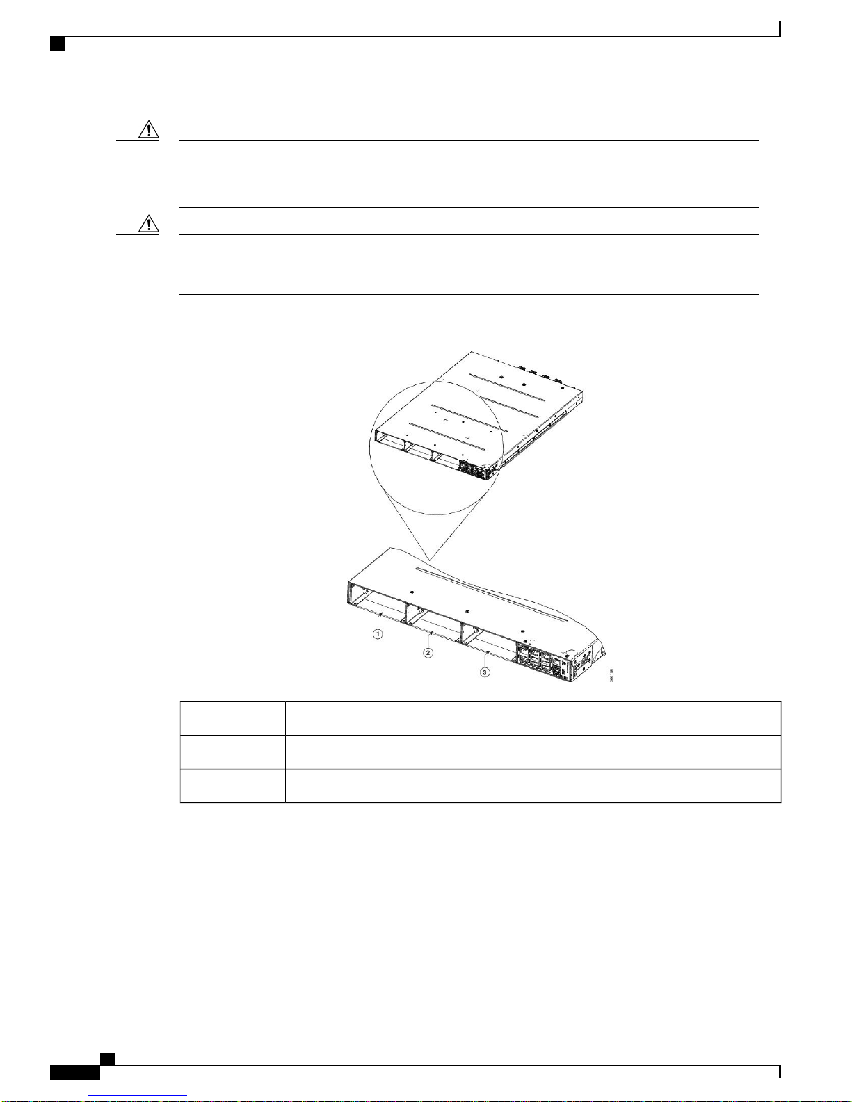
The optical modules can be inserted in slots 1 to 3 as shown in the following figure. The optical modules
can be inserted and removed from the slots while the system is operational. In amplified configuration,
the Optical Amplifier module can be inserted in any slot. In (section) protected configuration, the protect
Optical Amplifier module is inserted in slot 1, Protection Switching Module in slot 2, and working
Optical Amplifier module in slot 3.
Hardware Installation Guide for Cisco NCS 1001
1
Page 2
Cisco NCS 1001 Overview
Cisco NCS 1001 Overview
Caution
Caution
Each optical module must be inserted in a slot only when the module in the adjacent slot is completely
inserted and seated or the adjacent slot is empty. If an optical module is inserted in a slot without seating
the adjacent module, the ejector might interfere with the adjacent module.
The empty slots must be inserted with the filler optical modules or filler PSUs as appropriate to guarantee
safety and system cooling compliance. See Figure 1: Cisco NCS 1001 Front View, on page 2 and Figure
3: Cisco NCS 1001 Rear View, on page 3 to identify the slots for optical modules and PSUs respectively.
Figure 1: Cisco NCS 1001 Front View
Hardware Installation Guide for Cisco NCS 1001
2
Optical Module Slot 11
Optical Module Slot 22
Optical Module Slot 33
Page 3
Cisco NCS 1001 Overview
Cisco NCS 1001 Overview
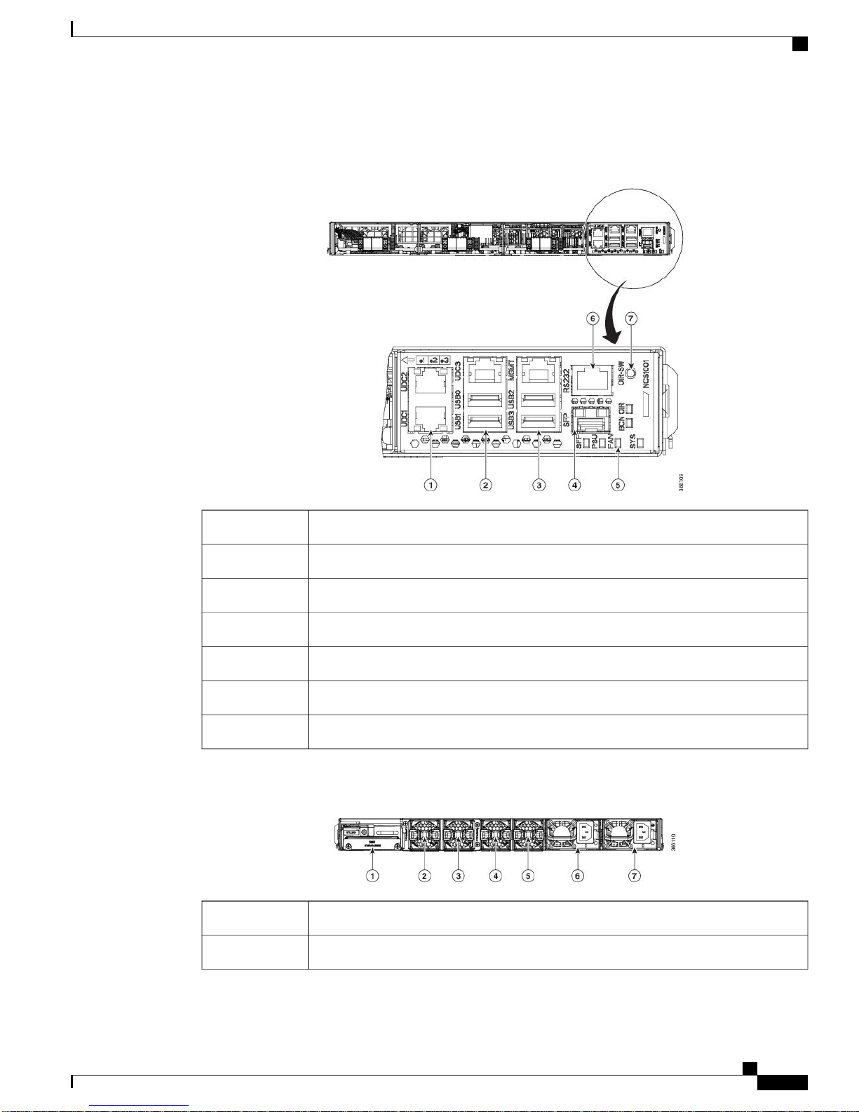
The slot numbers are also specified on the front panel label.
Figure 2: Cisco NCS 1001 Front View
UDC (user data channel) for optical modules 1 and 21
Two USB 2.0 ports and one UDC for optical module 32
Two USB 2.0 ports and one 10/100/1000 LAN electrical management interface3
10/100/1000 LAN management interface (optical)4
Status LED (SFP link, Power supply, Fan, System, Beacon, OIR)5
RS232 console port of the control card6
OIR switch7
Figure 3: Cisco NCS 1001 Rear View
Control card and SSD (Solid State Disk)1
Fan 32
Hardware Installation Guide for Cisco NCS 1001
3
Page 4

Cisco NCS 1001 Overview
Both the power supply modules shall be AC/DC or DC/DC. Mixed configuration is not allowed.
Benefits
NCS 1001 provides the following benefits.
Cisco NCS 1001 Overview
Fan 23
Fan 14
Fan 05
600W AC/DC or DC/DC redundant power supply module (PSU 1)6
600W AC/DC or DC/DC redundant power supply module (PSU 0)7
Up to 23dBm output power to allow for +3dBm per channel fiber launch power and maximum optical
•
performance for high baud rate and higher order modulation format transponders.
Switchable gain pre-amplifier up to 34db.
•
Embedded Optical Channel Monitoring (OCM) module to monitor per channel power at all the input
•
and output ports.
Integrated pluggable optics based OSC and OTDR support.
•
OSC supports user data channel transport as well as remote node management.
•
Supports 96 channels of C-Band in 1 RU.
•
Supports flex grid on OCM module.
•
Class 1M Laser Product Label
The Class 1M Laser Product label is shown in the following figure. Class 1M is guaranteed by the Automatic
Power Reduction procedure.
Figure 4: Class 1M Laser Product Label
Hardware Installation Guide for Cisco NCS 1001
4
Page 5

Cisco NCS 1001 Overview
Physical Characteristics
• Width: 17.44” (442.9 mm)
• Depth: 23.64” (600.5 mm)
Height: 1 RU
•
Weight without power supply unit: 8.2 kg
•
Weight with two power supply units: 10.5 kg
•
Weight of AC PSU: 1.162 kg
•
Weight of Fan: 78 gms
•
Weight of control card: 1.5 kg
•
Optical Amplifier Module
The optical amplifier module (NCS1K-EDFA) has pre-amplifier and booster amplifier.
The optical amplifier module provides the following functionality.
Optical Amplifier Module
Preamplifier (LINE-RX to COM-TX) - Single preamplifier variant, with switchable gain ranges, according
•
to link loss:
Range # 1: 0 to 24 dB gain, Tilt control: 24 to 27 gain, with tilt uncontrolled
◦
Range # 2: 20 to 34 dB gain, Tilt control: 34 to 37 dB gain, with tilt uncontrolled
◦
23dBm output power @ COM-TX port
◦
Booster amplifier (COM-RX to LINE-TX) - True variable gain booster amplifier
•
Gain range: 1 to 20. 20 to 25 uncontrolled tilt.
◦
23dBm output power @ LINE-TX port
◦
ADD/DROP OSC channel supports both 1510nm and 1610nm +/-10nm
•
OCM assesses channel presence and Gain regulation and per channel power monitoring.
•
Figure 5: EDFA Front View
Hardware Installation Guide for Cisco NCS 1001
5
Page 6

Protection Switching Module
Cisco NCS 1001 Overview
XFP for OSC and additional OTDR feature1
SFP for OSC (Optical Service Channel)2
Status LED3
Service Channel input and output port [OSC - RX, TX]4
5
The following table describes the mapping of controllers and optical ports for the optical amplifier module.
Ots 0/slot/0/0
Ots 0/slot/0/1
Ots 0/slot/0/2
PRE and BST amplifier inputs and output ports
[L (LINE) - RX, TX]
[C (COM) - RX, TX]
[COM - TX CHECK]
Optical PortsController
COM-RX (booster input)
•
COM-TX (preamplifier output)
•
LINE-RX (preamplifier input)
•
LINE-TX (booster output)
•
OSC-RX
•
OSC-TX
•
Protection Switching Module
The protection switching module (NCS1K-PSM) provides the following functionality.
In TX section:
•
Splits input optical channels to both working and protection lines.
◦
Forces the switch in the remote site by opening one of the two line paths (by putting the related
◦
VOA in AVS).
In RX section:
•
Selects the signals from working or protection line. Each line is monitored through a PD.
◦
Hardware Installation Guide for Cisco NCS 1001
6
COM-CHECKOts 0/slot/0/3
Page 7

Cisco NCS 1001 Overview
Balances the two line losses by changing the VOA attenuation value at the same time of the switch
◦
change of state.
Figure 6: PSM Front View
Protected path input and output port [P - RX, TX]1
Product IDs
Product IDs
Working path input and output port [W - RX, TX]2
COM input and output port [COM - RX, TX]3
Status LED4
The following table describes the mapping of controllers and optical ports for the protection switching module.
Optical PortsController
COM-TXOts 0/slot/0/0
Working path input and output port [W - RX, TX]Ots 0/slot/0/1
Protected path input and output port [P - RX, TX]Ots 0/slot/0/2
The following table describes the product IDs of the components.
DescriptionProduct ID
Network Convergence System 1001 line system 3 slotsNCS1001-K9=
Network Convergence System 1001 Control cardNCS1K-CNTLR2=
Network Convergence System 1001 amplifier moduleNCS1K-EDFA=
Network Convergence System 1001 protection moduleNCS1K-PSM=
Hardware Installation Guide for Cisco NCS 1001
7
Page 8

LEDs in Cisco NCS 1001
Cisco NCS 1001 Overview
DescriptionProduct ID
NCS1K-2KW-AC2=
NCS1K-2KW-DC=
LEDs in Cisco NCS 1001
Network Convergence System 1001 AC power supply unit - 2KW normal operating
temperature, 600W short term high temperature
Network Convergence System 1001 DC power supply unit - 2KW normal operating
temperature, 600W short term high temperature
Network Convergence System 1001 line system FanNCS1K1-FAN=
SSDNCS1K-SSD=
DescriptionStateLED
The unit is operating correctly.GreenSYS
The unit has one or more errors detected.Yellow
Power is not applied to the unit.Off
The unit needs attention.BlueBCN
Yellow
Off
RedOIR
Green
The unit does not need attention.Off
The SFP link is up.GreenSFP
The link is down, active alarms are present
on this port, or a hardware failure has
occurred.
The port is not provisioned by the software,
the optics module is missing, or the port does
not have power.
The unit is operating correctly.GreenPSU and FAN
The unit has one or more errors detected.Red
The control card is not present or not properly
inserted.
The control card, BIOS, and software are
functional.
Hardware Installation Guide for Cisco NCS 1001
8
 Loading...