

Cisco NAC3350-PROF-K9 - NAC Profiler Server, NAC-3315, NAC-3355, NAC-3395, NAC-3310 Installation Manual
...Page 1

Cisco NAC Appliance Hardware
Installation Guide
Release 4.8
Jan 2012
Americas Headquarters
Cisco Systems, Inc.
170 West Tasman Drive
San Jose, CA 95134-1706
USA
http://www.cisco.com
Tel: 408 526-4000
800 553-NETS (6387)
Fax: 408 527-0883
Text Part Number: OL-20326-01
Page 2

THE SPECIFICATIONS AND INFORMATION REGARDING THE PRODUCTS IN THIS MANUAL ARE SUBJECT TO CHANGE WITHOUT NOTICE. ALL
STATEMENTS, INFORMATION, AND RECOMMENDATIONS IN THIS MANUAL ARE BELIEVED TO BE ACCURATE BUT ARE PRESENTED WITHOUT
WARRANTY OF ANY KIND, EXPRESS OR IMPLIED. USERS MUST TAKE FULL RESPONSIBILITY FOR THEIR APPLICATION OF ANY PRODUCTS.
THE SOFTWARE LICENSE AND LIMITED WARRANTY FOR THE ACCOMPANYING PRODUCT ARE SET FORTH IN THE INFORMATION PACKET THAT
SHIPPED WITH THE PRODUCT AND ARE INCORPORATED HEREIN BY THIS REFERENCE. IF YOU ARE UNABLE TO LOCATE THE SOFTWARE LICENSE
OR LIMITED WARRANTY, CONTACT YOUR CISCO REPRESENTATIVE FOR A COPY.
The Cisco implementation of TCP header compression is an adaptation of a program developed by the University of California, Berkeley (UCB) as part of UCB’s public
domain version of the UNIX operating system. All rights reserved. Copyright © 1981, Regents of the University of California.
NOTWITHSTANDING ANY OTHER WARRANTY HEREIN, ALL DOCUMENT FILES AND SOFTWARE OF THESE SUPPLIERS ARE PROVIDED “AS IS” WITH
ALL FAULTS. CISCO AND THE ABOVE-NAMED SUPPLIERS DISCLAIM ALL WARRANTIES, EXPRESSED OR
LIMITATION, THOSE OF MERCHANTABILITY, FITNESS FOR A PARTICULAR PURPOSE AND NONINFRINGEMENT OR ARISING FROM A COURSE OF
DEALING, USAGE, OR TRADE PRACTICE.
IN NO EVENT SHALL CISCO OR ITS SUPPLIERS BE LIABLE FOR ANY INDIRECT, SPECIAL, CONSEQUENTIAL, OR INCIDENTAL DAMAGES, INCLUDING,
WITHOUT LIMITATION, LOST PROFITS OR LOSS OR DAMAGE TO DATA ARISING OUT OF THE USE OR INABILITY TO USE THIS MANUAL, EVEN IF CISCO
OR ITS SUPPLIERS HAVE BEEN ADVISED OF THE POSSIBILITY OF SUCH DAMAGES.
Cisco and the Cisco logo are trademarks or registered trademarks of Cisco and/or its affiliates in the U.S. and other countries. To view a list of Cisco trademarks, go to this
URL:
www.cisco.com/go/trademarks. Third-party trademarks mentioned are the property of their respective owners. The use of the word partner does not imply a partnership
relationship between Cisco and any other company. (1110R)
Nessus is the trademark of Tenable Network Security.
Cisco NAC Appliance - Clean Access Manager includes software developed by the Apache Software Foundation (http://www.apache.org/) Copyright © 1999-2000 The
Apache Software Foundation. All rights reserved. The APACHE SOFTWARE IS PROVIDED ''AS IS'' AND ANY EXPRESSED OR IMPLIED WARRANTIES,
INCLUDING, BUT NOT LIMITED TO, THE IMPLIED WARRANTIES OF MERCHANTABILITY AND FITNESS FOR A PARTICULAR PURPOSE ARE
DISCLAIMED. IN NO EVENT SHALL THE APACHE SOFTWARE FOUNDATION OR ITS CONTRIBUTORS OR CISCO OR ITS CONTRIBUTORS BE LIABLE FOR
ANY DIRECT, INDIRECT, INCIDENTAL, SPECIAL, EXEMPLARY, OR CONSEQUENTIAL DAMAGES (INCLUDING, BUT NOT LIMITED TO, PROCUREMENT
OF SUBSTITUTE GOODS OR SERVICES; LOSS OF USE, DATA, OR PROFITS; OR BUSINESS INTERRUPTION) HOWEVER CAUSED AND ON ANY THEORY
OF LIABILITY, WHETHER IN CONTRACT, STRICT LIABILITY, OR TORT (INCLUDING NEGLIGENCE OR OTHERWISE) ARISING IN ANY WAY OUT OF THE
USE OF THE APACHE SOFTWARE, EVEN IF ADVISED OF THE POSSIBILITY OF SUCH DAMAGE.
Any Internet Protocol (IP) addresses used in this document are not intended to be actual addresses. Any examples, command display output, and figures included in the
document are shown for illustrative purposes only. Any use of actual IP addresses in illustrative content is unintentional and coincidental.
Cisco NAC Appliance Hardware Installation Guide
© 2012 Cisco Systems, Inc. All rights reserved.
IMPLIED, INCLUDING, WITHOUT
Page 3

CONTENTS
About This Guide 7
Audience 7
Purpose 7
Document Organization 8
Document Conventions 8
New Features in this Release 8
Product Documentation 9
Documentation Updates 11
Obtaining Documentation and Submitting a Service Request 12
CHAPTER
1 Cisco NAC Appliance Hardware Platforms 1-1
About Cisco NAC Appliance 1-1
FIPS 140-2 Compliant and Non-FIPS Hardware Platforms 1-1
NAC-3315, NAC-3355, and NAC-3395 1-3
NAC-3315 Serial Number Location 1-5
Cisco NAC-3315 Front and Rear Panels 1-5
Front Panel Features 1-5
Rear Panel Features 1-6
NAC-3355 Serial Number Location 1-8
Cisco NAC-3355 Front and Rear Panels 1-8
Front Panel Features 1-8
Rear Panel Features 1-10
NAC-3395 Serial Number Location 1-12
Cisco NAC-3395 Front and Rear Panels 1-12
Front Panel Features 1-12
Rear Panel Features 1-14
NAC-3310, NAC-3350, and NAC-3390 1-16
Cisco NAC-3310 Front and Rear Panels 1-18
Front Panel Features 1-18
Rear Panel Features 1-20
Cisco NAC-3350 Front and Rear Panels 1-21
Front Panel Features 1-21
Rear Panel Features 1-23
Cisco NAC-3390 Front and Rear Panels 1-24
OL-20326-01
Cisco NAC Appliance Hardware Installation Guide
1
Page 4

Contents
Front Panel Features 1-25
Rear Panel Features 1-26
Cisco Product Identification Tool 1-27
CHAPTER
2 Preparing for Installation 2-1
Safety Guidelines 2-2
General Precautions 2-2
Safety with Equipment 2-3
Safety with Electricity 2-3
Preventing Electrostatic Discharge Damage 2-5
Lifting Guidelines 2-5
Preparing Your Site for Installation 2-6
Site Planning 2-6
Rack Installation Safety Guidelines 2-7
Site Environment 2-8
Airflow Guidelines 2-9
Temperature and Humidity Guidelines 2-9
Power Considerations 2-9
Method of Procedure 2-10
Shipping Package Contents 2-10
Failover Bundles 2-11
Required Equipment 2-11
Configuration Worksheets 2-11
Clean Access Manager (CAM) Configuration Worksheet 2-12
Clean Access Server (CAS) Configuration Worksheet 2-12
CAS Mode IP Addressing Considerations 2-13
Rack-Mounting Your Cisco NAC Appliance CAM/CAS 2-14
Mounting the NAC-3315 Appliance in a 4-Post Rack 2-15
NAC-3315 4-Post Rack-Mount Hardware Kit 2-15
Installing the NAC-3315 Slide Rails into a Rack 2-16
Installing the NAC-3315 Appliance into the Slide Rails 2-19
Mounting the NAC-3355/3395 Appliance in a Four-Post Rack 2-21
NAC-3355/3395 4-Post Rack-Mount Hardware Kit 2-22
Installing the NAC-3355/3395 Slide Rails Into the 4-Post Rack 2-22
Installing the NAC-3355/3395 Appliance Into the Slide Rails 2-25
Cisco NAC Appliance Licensing 2-26
Upgrading Cisco NAC Appliance Software 2-27
Downloading Cisco NAC Appliance Software 2-28
Upgrading Firmware 2-28
Cisco NAC Appliance Hardware Installation Guide
2
OL-20326-01
Page 5

Contents
CHAPTER
3 Installing the Clean Access Manager and Clean Access Server 3-1
Overview 3-1
Important Release Information 3-2
Installing the Clean Access Manager 3-2
Overview 3-2
Summary of Steps For New Installation 3-3
Connect the Clean Access Manager 3-4
Install the Clean Access Manager (CAM) Software from CD-ROM 3-5
Perform the Initial CAM Configuration 3-6
Configuration Utility Script 3-6
Access the CAM Web Console 3-11
Install CAM License 3-13
Add Additional Licenses 3-15
Important Notes for SSL Certificates 3-17
Installing the Clean Access Server 3-18
Overview 3-18
Switch/Router Configuration 3-18
Virtual Gateway Mode Connection Requirements 3-19
Switch Support for CAS Virtual Gateway/VLAN Mapping (IB and OOB) 3-20
Determining VLANs For Virtual Gateway 3-20
Summary of Steps For New Installation 3-21
Connect the Clean Access Server 3-22
Install the Clean Access Server (CAS) Software from CD-ROM 3-22
Perform the Initial CAS Configuration 3-24
Configuration Utility Script 3-24
Important Notes for SSL Certificates 3-33
Cisco NAC Appliance Connectivity Across a Firewall 3-34
Configuring the CAS Behind a NAT Firewall 3-36
Connectivity Across a Wide Area Network 3-37
Configuring Additional NIC Cards 3-37
Serial Connection to the CAM and CAS 3-39
Configuring Boot Settings on the Cisco NAC Appliance CAM/CAS 3-40
Useful CLI Commands for the CAM/CAS 3-42
CAM CLI Commands 3-42
CAS CLI Commands 3-43
CAS CLI Commands for Cisco NAC Appliance 3-43
CAS CLI Commands for Cisco NAC Profiler 3-44
Manually Restarting the CAM/CAS Configuration Utility 3-46
OL-20326-01
Cisco NAC Appliance Hardware Installation Guide
3
Page 6

Contents
Troubleshooting the Installation 3-47
Verify/Change Current Master Secret on CAM/CAS 3-48
Recover From Corrupted Master Secret 3-48
Network Interface Card (NIC) Driver Not Supported 3-49
Resetting and Restoring an Unreachable Clean Access Server 3-49
Enabling TLSv1 on Internet Explorer Version 6 3-49
Powering Down the NAC Appliance 3-50
CHAPTER
4 Configuring High Availability (HA) 4-1
Adding High Availability Cisco NAC Appliance To Your Network 4-1
Installing a Clean Access Manager High Availability Pair 4-3
CAM High Availability Overview 4-4
Before Starting 4-7
Connect the Clean Access Manager Machines 4-8
Serial Connection 4-9
Configure the HA-Primary CAM 4-9
Configure the HA-Secondary CAM 4-12
Complete the Configuration 4-16
Upgrading an Existing Failover Pair 4-16
Failing Over an HA-CAM Pair 4-16
Accessing High Availability Pair CAM Web Consoles 4-17
Determining Active and Standby CAM 4-17
Determining Primary and Secondary CAM 4-17
Installing a Clean Access Server High Availability Pair 4-17
CAS High Availability Overview 4-18
CAS High Availability Requirements 4-22
Before Starting 4-24
Selecting and Configuring the Heartbeat UDP Interface 4-25
Serial Port High-Availability Connection 4-26
Configure High Availability 4-26
Configure the HA-Primary Clean Access Server 4-27
Configure the HA-Secondary Clean Access Server 4-34
Connect the Clean Access Servers and Complete the Configuration 4-38
Failing Over an HA-CAS Pair 4-39
Modifying CAS High Availability Settings 4-40
To Change IP Settings for an HA-CAS 4-40
Upgrading an Existing Failover Pair 4-41
Configuring High Availability for Virtual Gateway Mode 4-42
Useful CLI Commands for HA 4-43
Cisco NAC Appliance Hardware Installation Guide
4
OL-20326-01
Page 7

Clean Access Manager 4-43
Clean Access Server 4-44
HA CAS Configuration Status 4-44
Heartbeat/Link-Based Connections 4-44
Link-Detect Interfaces 4-45
Active/Standby Status 4-45
Accessing High Availability Pair CAS Web Consoles 4-46
Determining Active and Standby CAS 4-46
Determining Primary and Secondary CAS 4-46
Contents
CHAPTER
APPENDIX
I
NDEX
5 Password Recovery 5-1
Recovering Root Password for CAM/CAS 5-1
Recovering Root Password for CAM/CAS (Release 3.5.x or Below) 5-1
A Open Source License Acknowledgements A-1
Notices A-1
OpenSSL/Open SSL Project A-1
License Issues A-1
OL-20326-01
Cisco NAC Appliance Hardware Installation Guide
5
Page 8

Contents
Cisco NAC Appliance Hardware Installation Guide
6
OL-20326-01
Page 9

About This Guide
Revised January 18, 2012, OL-20326-01
This preface includes the following sections:
• Audience
• Purpose
• Document Organization
• Document Conventions
• New Features in this Release
• Product Documentation
Audience
Purpose
• Documentation Updates
• Obtaining Documentation and Submitting a Service Request
This guide is for network administrators who are installing the Cisco NAC Appliance hardware and
performing initial configuration to introduce the Clean Access Manager (CAM) and Clean Access Server
(CAS) into the network. Use this document along with the
Manager Configuration Guide, Release 4.8(3) and Cisco NAC Appliance - Clean Access Server
Configuration Guide, Release 4.8(3) to install, configure, and administer your Cisco NAC Appliance
deployment.
The Cisco NAC Appliance Hardware Installation Guide, Release 4.8 describes how to install and
initially configure the Clean Access Manager and Clean Access Server on all Cisco NAC Appliance
platforms. Once you have installed and initially configured the CAM and CAS, you can use the Clean
Access Manager (CAM) and its web-based administration console to manage multiple Clean Access
Servers (CASs) in a deployment. End users connect through the Clean Access Server to the network via
web login or Cisco NAC Agent. This guide also describes how to implement High Availability for the
CAMs and CASs in your network.
See the Product Documentation section for further details on the document set for Cisco NAC
Appliance.
Cisco NAC Appliance - Clean Access
OL-20326-01
Cisco NAC Appliance Hardware Installation Guide
7
Page 10

Document Organization
This guide combines hardware and installation information for both the Clean Access Manager and
Clean Access Server. Starting from Release 4.7(0), the Cisco NAC Appliance Hardware Installation
Guide replaces the installation chapters that were formerly located in the Cisco NAC Appliance - Clean
Access Manager Installation and Configuration Guide and Cisco NAC Appliance - Clean Access Server
Installation and Configuration Guide.
Table 1 Document Organization
Chapter Description
Chapter 1, “Cisco NAC Appliance Hardware
Platforms”
Chapter 2, “Preparing for Installation” Outlines the steps necessary to ensure your
Chapter 3, “Installing the Clean Access Manager
and Clean Access Server”
Chapter 4, “Configuring High Availability (HA)” Describes how to set up a pair of Clean Access
Chapter 5, “Password Recovery” Defines the steps necessary to recover a lost Cisco
Appendix A, “Open Source License
Acknowledgements”
About This Guide
Provides information about the hardware
platforms available in Cisco NAC Appliance
environment is ready to install Cisco NAC
Appliance hardware
Describes how to install and initially configure the
Clean Access Manager and Clean Access Server
Manager or Clean Access Server machines for
high availability
NAC Appliance root password
Contains Open Source License information for
Cisco products
Document Conventions
Table 2 Document Conventions
Item Convention
Indicates command line output. Screen font
Indicates information you enter. Boldface screen font
Indicates variables for which you supply values. Italic screen font
Indicates web admin console modules, menus, tabs, links and
submenu links.
Indicates a menu item to be selected. Administration > User Pages
New Features in this Release
For a brief summary of the new features and enhancements available in this release refer to
Documentation Updates and the “New and Changed Information” section of the Release Notes for Cisco
NAC Appliance corresponding to your latest Cisco NAC Appliance release version.
Boldface font
Cisco NAC Appliance Hardware Installation Guide
8
OL-20326-01
Page 11

About This Guide
Product Documentation
Table 3 lists the technical documentation available for Cisco NAC Appliance on Cisco.com at
http://www.cisco.com/en/US/products/ps6128/tsd_products_support_series_home.html.
When using the online publications, refer to the documents that match the software version running on
your Cisco
See also the following product literature for additional details:
• Cisco NAC Appliance Data Sheet
• Cisco NAC Appliance Ordering Guide
Tip To access external URLs referenced in the PDF of this document, right-click the link in Adobe Acrobat
and select “Open in Weblink in Browser.”
Table 3 Cisco NAC Appliance Document Set
Document Title Refer to This Document For Information On:
Cisco NAC Appliance Service
Contract/Licensing Support
Supported Hardware and System Requirements
for Cisco NAC Appliance
Regulatory Compliance and Safety Information
for Cisco 1121 Secure Access Control System,
Cisco NAC Appliance, Cisco NAC Guest Server,
and Cisco NAC Profiler
Support Information for Cisco NAC Appliance
Agents, Release 4.5 and Later
Switch Support for Cisco NAC Appliance • Which switches and NMEs support OOB
NAC Appliance (e.g. “Release 4.8”).
• Obtaining and installing product licenses
• Information on service contracts, ordering and
RMA
• Supported Hardware Platforms,
Troubleshooting Network Card Driver Support
Issues, and System Requirements
• Regulatory Compliance and Safety Information
• Agent System Requirements, Agent/Server
Version Compatibility, Agent/OS/Browser
Support Matrix, Agent/AD Server
Compatibility for AD SSO, and Agent
Localized Language Template Support
deployment
Connecting Cisco Network Admission Control
Network Modules
Cisco NAC Appliance FIPS Card
Field-Replaceable Unit Installation Guide
OL-20326-01
• Known issues/troubleshooting for switches and
WLCs
• Connecting Cisco NAC network module
(NME-NAC-K9) in an Integrated Services
Router
• Provides instructions to upgrade your existing
Cisco NAC-3310, NAC-3350, and NAC-3390
with a field-replaceable FIPS card necessary to
introduce FIPS compliance in your network
Cisco NAC Appliance Hardware Installation Guide
9
Page 12

About This Guide
Table 3 Cisco NAC Appliance Document Set
Document Title Refer to This Document For Information On:
Release Notes for Cisco NAC Appliance Details on the latest 4.8(x) release, including:
• New features and enhancements
• Fixed caveats
• Upgrade instructions
• Supported AV/AS product charts
• CAM/CAS/Agent compatibility and version
information
Cisco NAC Appliance Hardware Installation
Guide, Release 4.8
Cisco NAC Appliance - Clean Access Manager
Configuration Guide, Release 4.8(3)
Details on CAM/CAS installation topics:
• Hardware specifications on the various
CAM/CAS platforms
• How to install the Clean Access Manager and
Clean Access Server Platforms
• How to install Cisco NAC Appliance software
on the CASM/CAS
• How to configure CAM and CAS pairs for High
Availability
Complete CAM details, including:
• How to install the CAM software
• Overviews of major concepts and features of
Cisco NAC Appliance
• How to use the CAM web console to perform
global configuration of Cisco NAC Appliance
(applying to all CASs in the deployment)
10
Cisco NAC Appliance - Clean Access Server
Configuration Guide, Release 4.8(3)
Cisco NAC Appliance Hardware Installation Guide
• How to configure CAM pairs for High
Availability
CAS-specific details, including:
• How to install the CAS software
• Where to deploy the CAS on the network
(general information)
• How to perform local (CAS-specific)
configuration using the CAS management
pages of the CAM web console, or the CAS
direct access console
• How to configure CAS pairs for High
Availability
OL-20326-01
Page 13

About This Guide
Table 3 Cisco NAC Appliance Document Set
Document Title Refer to This Document For Information On:
Cisco NAC Profiler Installation and
Configuration Guide
Cisco NAC Appliance Migration Guide - Release
4.1(8) to Release 4.7(0)
Documentation Updates
Table 4 Updates to Cisco NAC Appliance Hardware Installation Guide, Release 4.8
Date Description
1/18/12 Release 4.8(3)
• Updated Upgrading Cisco NAC Appliance Software, page 2-27
• Details on installing and configuring the Cisco
NAC Profiler Server /Collector
• Upgrading from an earlier Cisco NAC
Appliance release on non-Cisco hardware to a
next generation (NAC-3315/3355/3395)
platform using the Cisco NAC Appliance
Migration utility
• Updated Release 4.8(3) screenshots as appropriate
6/2/11 Added a security advisory regarding the serial console connection to Serial Connection to
the CAM and CAS, page 3-39, Serial Connection, page 4-9, and Serial Port
High-Availability Connection, page 4-26
5/3/11 Release 4.8(2)
• Updated Upgrading Cisco NAC Appliance Software, page 2-27
• Updated Release 4.8(2) screenshots as appropriate
1/31/11 Release 4.8(1)
• Updated Upgrading Cisco NAC Appliance Software, page 2-27
• Updated Release 4.8(1) screenshots as appropriate
12/7/10 Added a note about number of users supported by NAC-3315 and NAC-3310, when they
are FIPS-Compliant, to
Cisco NAC-3315 Front and Rear Panels, page 1-5 and Cisco
NAC-3310 Front and Rear Panels, page 1-18
10/5/10 Updated the Hardware Specification for NAC-3315 in Cisco NAC Appliance Hardware
Summary
9/9/10 Added note about installing and running Release 4.8 on CCA-3140s to FIPS 140-2
Compliant and Non-FIPS Hardware Platforms, page 1-1 and Upgrading Cisco NAC
Appliance Software, page 2-27
8/16/10 Adjusted FIPS card position on NAC-3355/3395 chassis rear panel views:
• Cisco NAC-3355 Front and Rear Panels, page 1-8
• Cisco NAC-3395 Front and Rear Panels, page 1-12
7/26/10 Release 4.8
OL-20326-01
Cisco NAC Appliance Hardware Installation Guide
11
Page 14

About This Guide
Obtaining Documentation and Submitting a Service Request
For information on obtaining documentation, submitting a service request, and gathering additional
information, see the monthly What’s
revised Cisco
http://www.cisco.com/en/US/docs/general/whatsnew/whatsnew.html
Subscribe to the What’s New in Cisco Product Documentation as an RSS feed and set content to be
delivered directly to your desktop using a reader application. The RSS feeds are a free service. Cisco currently
supports RSS
technical documentation, at:
Version 2.0.
New in Cisco Product Documentation, which also lists all new and
Cisco NAC Appliance Hardware Installation Guide
12
OL-20326-01
Page 15

Cisco NAC Appliance Hardware Platforms
This chapter provides general information on the Cisco NAC Appliance network access control system,
as well as hardware specifications for all Clean Access Manager (CAM) and Clean Access Server (CAS)
platforms available from Cisco Systems, Inc.
This chapter covers the following topics:
• About Cisco NAC Appliance, page 1-1
• NAC-3315, NAC-3355, and NAC-3395, page 1-3
• NAC-3310, NAC-3350, and NAC-3390, page 1-16
• Cisco Product Identification Tool, page 1-27
About Cisco NAC Appliance
Cisco® NAC Appliance is a Network Admission Control (NAC) product that allows network
administrators to authenticate, authorize, evaluate, and remediate wired, wireless, and remote users and
their machines prior to allowing users onto the network. It identifies whether networked devices such as
laptops, desktops, and corporate assets are compliant with a network's security policies, and it repairs
any vulnerabilities before permitting access to the network.
Cisco NAC Appliance is a network-centric integrated solution administered from the web console of the
Clean Access Manager (CAM), enforced through the Clean Access Server (CAS), and applied on clients
through the Cisco NAC Agent and Cisco NAC Web Agent client software. You can deploy the Cisco
NAC Appliance solution in the configuration that best meets the needs of your network.
CHAPTER
1
FIPS 140-2 Compliant and Non-FIPS Hardware Platforms
FIPS 140-2 compliant and non-FIPS Cisco NAC Appliance hardware platforms are Linux-based network
hardware appliances which are pre-installed with either the CAM or CAS application, the operating
system, and all relevant components on a dedicated server machine. In Release 4.7(0) and later, the
operating system comprises a hardened Linux kernel based on CentOS 5.3. Cisco NAC Appliance does
not support the installation of any other packages or applications onto a CAM or CAS dedicated
machine.
OL-20326-01
Cisco NAC Appliance Hardware Installation Guide
1-1
Page 16

About Cisco NAC Appliance
Cisco NAC Appliance Releases 4.8(x) only support and can only be installed on the following Cisco
NAC Appliance platforms:
Platform FIPS Option Non-FIPS Option
NAC-3315 CAM/CAS
NAC-3355 CAM/CAS
NAC-3395 CAM
NAC-3310 CAM/CAS Yes (with FIPS card
NAC-3350 CAM/CAS Yes (with FIPS card
NAC-3390 CAM Yes (with FIPS card
NAC-3140 (EOL)
1. If the FIPS card in a Cisco NAC-3315/3355/3395 CAM/CAS ceases to work correctly, make sure the FIPS card operation
2. Cisco NAC Appliance Release 4.8(1) and later do not support CCA-3140.
3. The Cisco CCA-3140 (CCA-3140-H1) NAC Appliance (EOL) requires CD installation of either the Clean Access Server or
Chapter 1 Cisco NAC Appliance Hardware Platforms
1
1
1
2,3
switch is set to “O” (for operational mode), as described in the “FIPS 140-2 Compliance” section of the
Cisco NAC Appliance corresponding to your latest Cisco NAC Appliance release version. If the FIPS card is still not
operational, you will need to RMA the appliance with Cisco Systems and replace it with a new Cisco NAC-3315/3355/3395.
Refer to the “
Support document for details.
Clean Access Manager software. Due to limited hardware resources on the CCA-3140, some combinations of Release 4.8
features may cause undesirable system behavior. If you are experiencing problems with Release 4.8 on the CCA-3140, please
contact the Cisco Technical Assistance Center (TAC).
Cisco NAC Appliance RMA and Licensing” section of the Cisco NAC Appliance Service Contract/Licensing
Yes Yes
Yes Yes
Yes Yes
Yes
field-replaceable unit only)
Yes
field-replaceable unit only)
Yes
field-replaceable unit only)
No Yes
Release Notes for
Refer to the Release Notes for Cisco NAC Appliance corresponding to your latest Cisco NAC Appliance
release version, for additional hardware compatibility information, including issues regarding FIPS
140-2 compliance.
Table 1-1 and Table 1-2 summarize the hardware specifications for each Cisco NAC Appliance. See the
“Diagrams” column for links to detailed diagrams showing NIC ports, power supply sockets, LEDs and
buttons.
Cisco NAC Appliance Hardware Installation Guide
1-2
OL-20326-01
Page 17

Chapter 1 Cisco NAC Appliance Hardware Platforms
NAC-3315, NAC-3355, and NAC-3395
Table 1-1 Cisco NAC Appliance Hardware Summary
Cisco NAC
Appliance
NAC-3315
Product Hardware Specifications Diagrams
MANAGER
Lite Manager
supporting up to 3
standalone or
HA-pair CASs
SERVER
CAS supporting
100, 250, or 500
users
• Single processor: Quad-core Intel Xeon (Core 2
quad)
• 4GB RAM
• 2 x 250 GB SATA HDD
• 4 10/100/1000 LAN ports [2 integrated NICs; 2
Gigabit NICs (PCI-E)]
• CD/DVD-ROM Drive
• 4 USB Ports (2 front, 2 rear)
• Power supply: 350W
Note The NAC-3315 is based on the IBM System
x3250 M2 server platform.
NAC-3315, NAC-3355, and NAC-3395
• Figure 1-2 on
page 1-5 “Cisco
NAC-3315 Front
Panel”
• Figure 1-3 on
page 1-6 “Cisco
NAC-3315 Front
Panel LEDs/Buttons”
• Figure 1-4 on
page 1-6 “Cisco
NAC-3315 (With
Installed FIPS Card)
Rear Panel”
• Figure 1-5 on
page 1-7 “Cisco
NAC-3315 (With
Installed FIPS Card)
Rear Panel LEDs”
OL-20326-01
Cisco NAC Appliance Hardware Installation Guide
1-3
Page 18

Chapter 1 Cisco NAC Appliance Hardware Platforms
NAC-3315, NAC-3355, and NAC-3395
Table 1-1 Cisco NAC Appliance Hardware Summary (continued)
Cisco NAC
Appliance Product Hardware Specifications Diagrams
NAC-3355
NAC-3395
MANAGER
Standard Manager
supporting up to 20
standalone or
HA-pair CASs
SERVER
CAS supporting
1500, 2500, or
3500 and 5000
users
MANAGER
Super Manager
supporting up to 40
standalone or
HA-pair CASs
• Single processor: Quad-core Intel Xeon
(Nehalem)
• 4 GB RAM
• 2 x 300 GB SAS RAID HDD
• 4 10/100/1000 LAN ports [2 integrated NICs; 2
Gigabit NICs (PCI-E)]
• CD/DVD-ROM Drive
• 4 USB Ports (1 front, 1 internal, 2 rear)
• Cavium CN1120-NHB-E SSL Accelerator Card or
nCipher Card (FIPS 140-2 Level 2 Common
Criteria EAL2)
• Power supply: Dual 675W (redundant)
Note The NAC-3355 is based on the IBM System
x3550 M2 server platform.
• Dual processor: 2 x Quad-core Intel Xeon
(Nehalem)
• 8GB RAM
• 4 x 300 GB SAS RAID HDD
• 4 10/100/1000 LAN ports [2 integrated NICs; 2
Gigabit NICs (PCI-E)]
• CD/DVD-ROM Drive
• 4 USB Ports (1 front, 1 internal, 2 rear)
• Cavium CN1120-NHB-E SSL Accelerator Card or
nCipher Card (FIPS 140-2 Level 2 Common
Criteria EAL2)
• Power supply: Dual 675W (redundant)
Note The NAC-3395 is based on the IBM System
x3550 M2 server platform.
• Figure 1-7 on
page 1-8 “Cisco
NAC-3355 Front
Panel”
• Figure 1-8 on
page 1-9 “Cisco
NAC-3355 Front
Panel LEDs/Buttons”
• Figure 1-9 on
page 1-10 “Cisco
NAC-3355 (With
Installed FIPS Card)
Rear Panel”
• Figure 1-10 on
page 1-10 “Cisco
NAC-3355 (With
Installed FIPS Card)
Rear Panel LEDs”
• Figure 1-12 on
page 1-12 “Cisco
NAC-3395 Front
Panel”
• Figure 1-13 on
page 1-13 “Cisco
NAC-3395 Front
Panel LEDs/Buttons”
• Figure 1-14 on
page 1-14 “Cisco
NAC-3395 (With
Installed FIPS Card)
Rear Panel”
• Figure 1-15 on
page 1-14 “Cisco
NAC-3395 (With
Installed FIPS Card)
Rear Panel LEDs”
Cisco NAC Appliance Hardware Installation Guide
1-4
OL-20326-01
Page 19
Chapter 1 Cisco NAC Appliance Hardware Platforms
195683
Cisco NAC 3315 Series
NAC Manager
CISCO
XXXXNNNNNNN
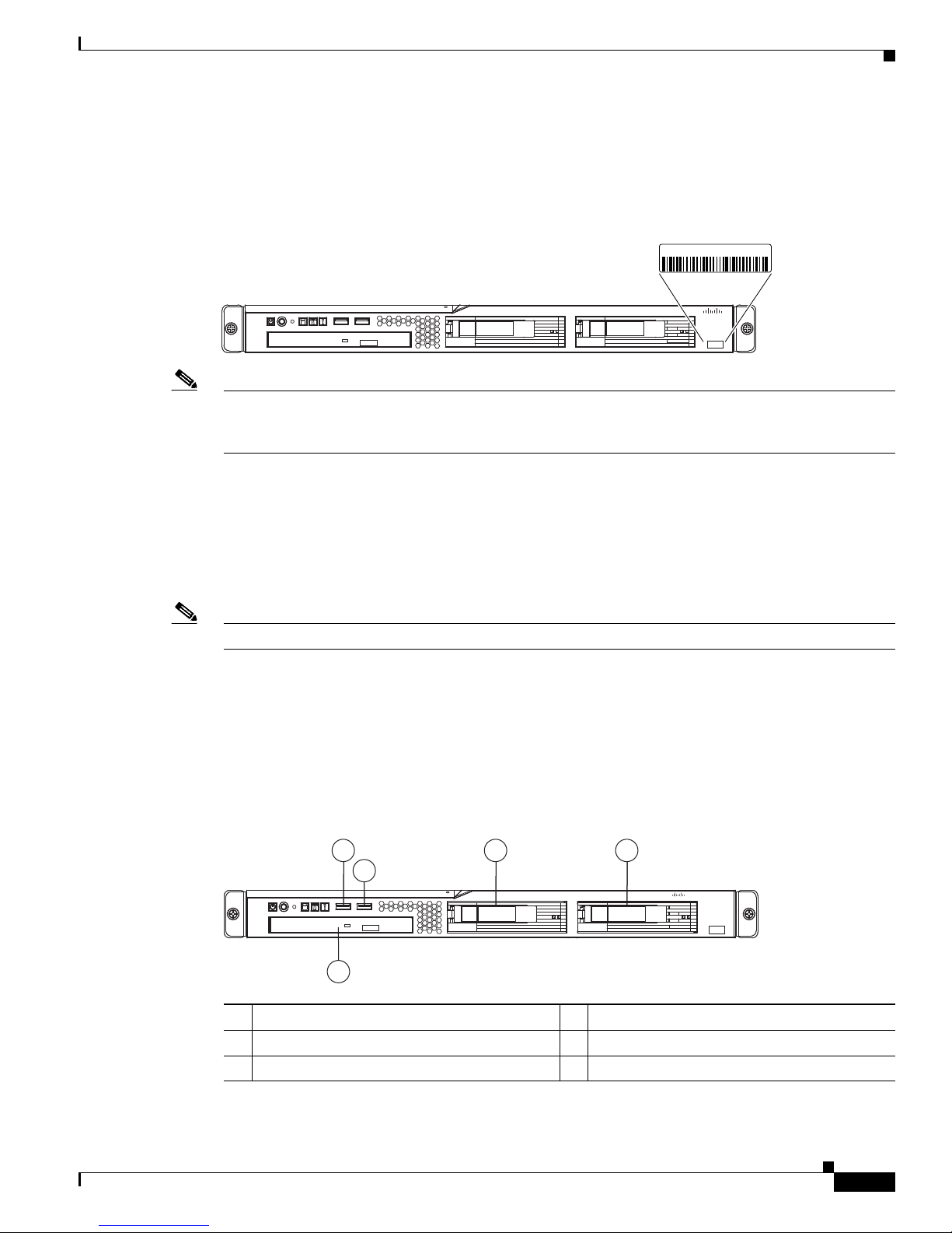
NAC-3315 Serial Number Location
The serial number label is located at the lower left of the front-panel of the NAC-3315. (See Figure 1-1.)
Figure 1-1 NAC-3315 Appliance Serial Number Location
Note The serial number for the NAC-3315 is 7 characters long. You can also view the NAC-3315 serial
number location on the Cisco Support website using the Cisco Product Identification Tool. For details,
see Cisco Product Identification Tool, page 1-27.
NAC-3315, NAC-3355, and NAC-3395
Cisco NAC-3315 Front and Rear Panels
The Cisco NAC-3315 platform is recommended for Clean Access Lite Manager and Clean Access Server
(100/250/500 user count) deployments. A NAC-3315 CAM Lite can manage up to 3 Clean Access
Servers or 3 HA-CAS pairs. A NAC-3315 CAS can support 100, 250, or 500 users.
Note FIPS 140-2 compliant NAC-3315 CAS can support only 250 or 500 users.
The Cisco NAC-3315 comes equipped with 4 network interfaces to provide flexibility in NIC interface
selection and to facilitate CAS high availability configuration.
For additional details, see FIPS 140-2 Compliant and Non-FIPS Hardware Platforms, page 1-1.
Front Panel Features
Figure 1-2 Cisco NAC-3315 Front Panel
1 3 4
2
CISCO
Cisco NAC 3315 Series
NAC Manager
195197
1
Front USB port 1
2
Front USB port 2
3
Hard disk drive (HDD) bay 0
OL-20326-01
5
4
Hard disk drive (HDD) bay 2
5
CD-ROM/DVD drive
Cisco NAC Appliance Hardware Installation Guide
1-5
Page 20
NAC-3315, NAC-3355, and NAC-3395
12 11 9 7 6
10 8
195199
1
53
42
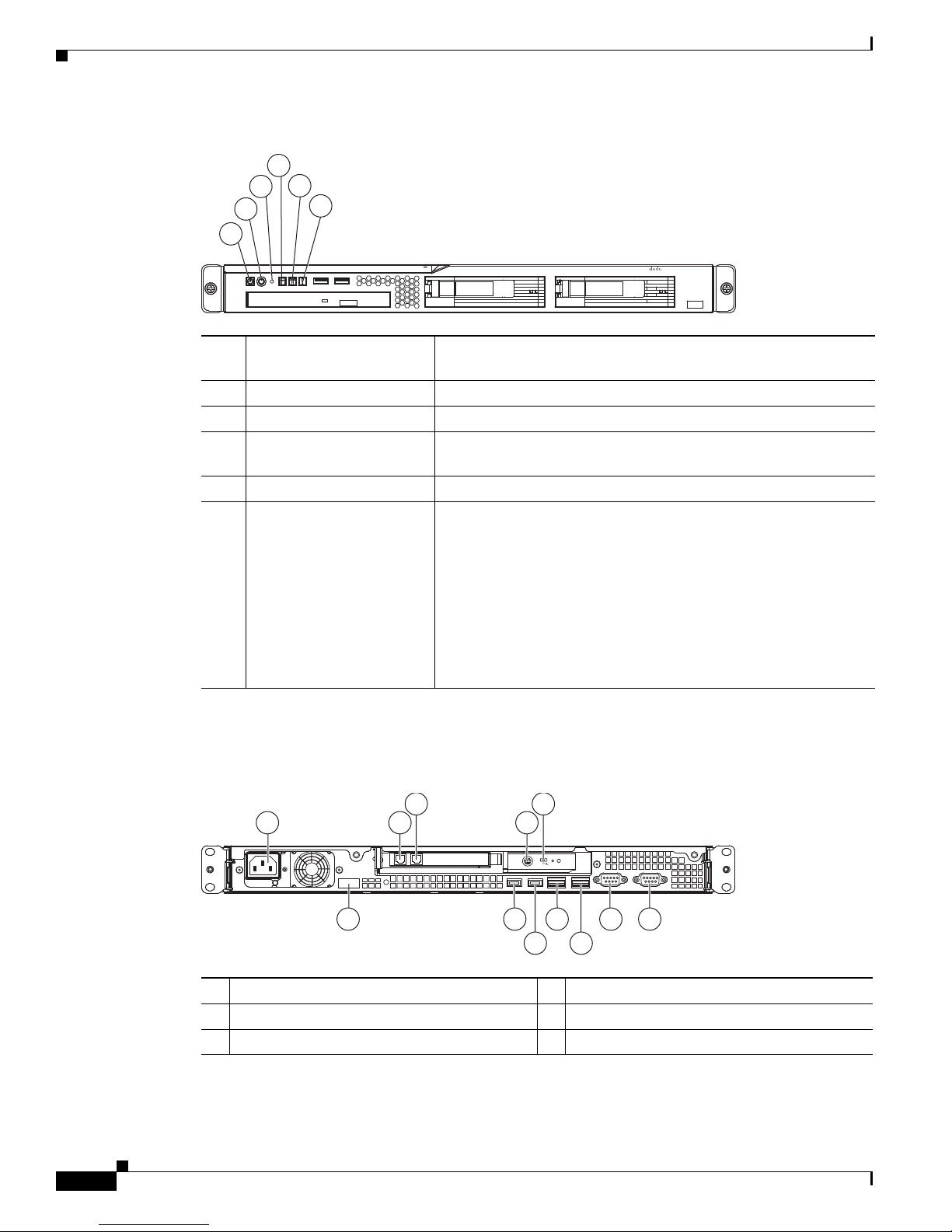
Figure 1-3 Cisco NAC-3315 Front Panel LEDs/Buttons
2
1
1
2
3
4
5
6
Chapter 1 Cisco NAC Appliance Hardware Platforms
4
5
3
6
Cisco NAC 3315 Series
CISCO
NAC Manager
195198
Power status LED Green = The appliance has AC power and is powered up
Off = The appliance is powered off (AC power disconnected)
Power button (recessed)
Reset button (recessed)
HDD activity LED Flashing green = Ongoing drive activity
Off = No drive activity
Locator button/LED Flashing blue = The Locator button has been pressed
System health LED Off = System health is normal
Amber = A pre-failure system threshold has been breached. This
can be any of the following:
• At least one fan failure (system or processor fan)
• At least one of the temperature sensors reached critical level
(system or processor thermal sensors)
Rear Panel Features
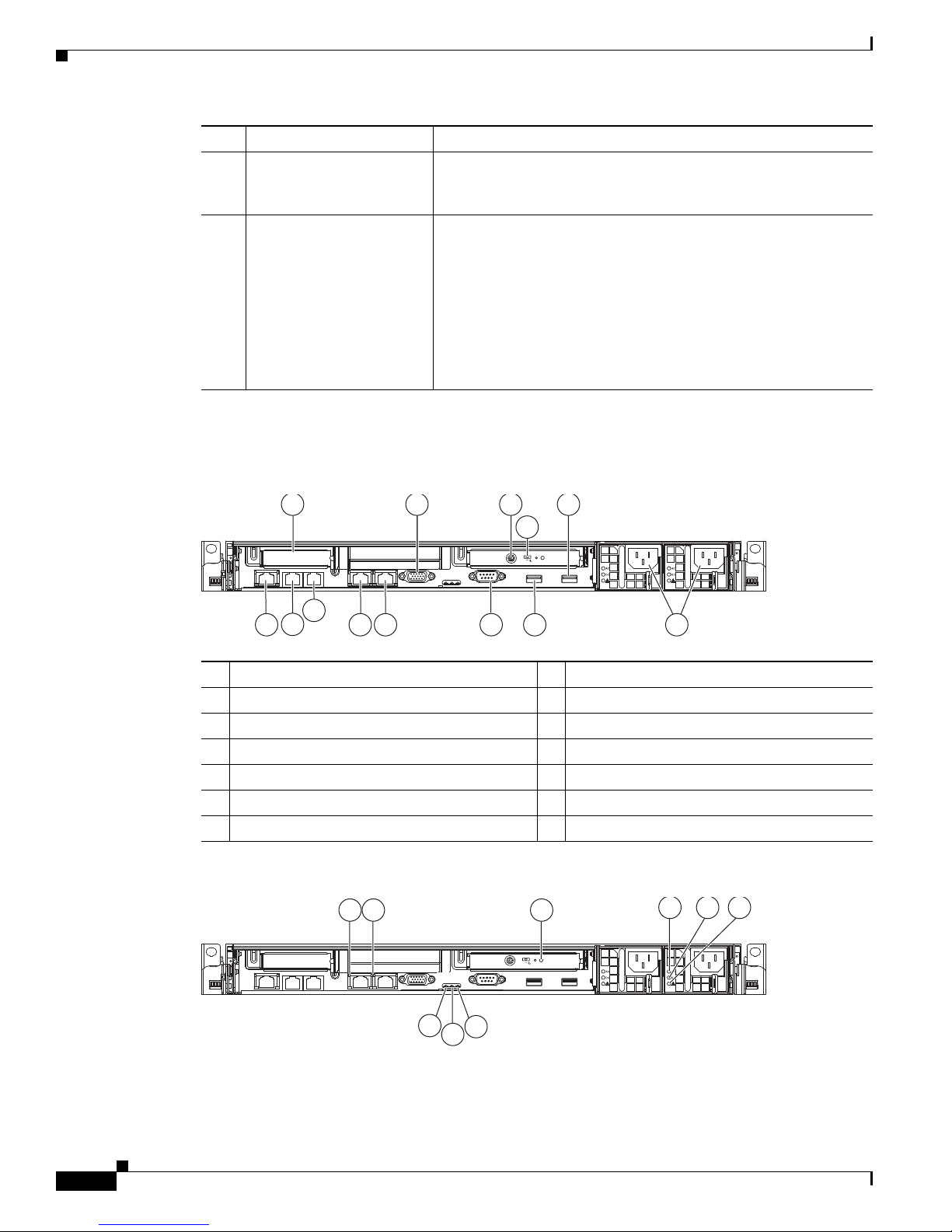
Figure 1-4 Cisco NAC-3315 (With Installed FIPS Card) Rear Panel
1
2
3
Power supply cable socket
NIC 3 (eth2) add-on card
NIC 4 (eth3) add-on card
• At least one memory module failure
• A power supply unit error has occurred
7
Video port
8
NIC 2 (eth1) GbE interface
9
NIC 1 (eth0) GbE interface
Cisco NAC Appliance Hardware Installation Guide
1-6
OL-20326-01
Page 21

Chapter 1 Cisco NAC Appliance Hardware Platforms
2 5
3 4
195200
1
NAC-3315, NAC-3355, and NAC-3395
4
FIPS card mini-DIN Smart card reader port
5
FIPS card mode switch
6
Serial port
Figure 1-5 Cisco NAC-3315 (With Installed FIPS Card) Rear Panel LEDs
1
FIPS card status LED Solid blue occasionally blinking off = FIPS card is enabled and
accepting commands
10
Rear USB port 4
11
Rear USB port 3
12
Console port
Two short blue flashes followed by a pause = FIPS card is in
initialization mode
Two longer blue flashes followed by a pause = FIPS card is in
maintenance mode
Repeatedly flashing morse code distress call (. . . - - - . . .)—three
short blue flashes followed by three longer blue flashes followed
again by three more short blue flashes = FIPS card is in error mode
Off = There is no power source connected to the FIPS card
2
NIC 1 (eth0) activity LED Green = Activity exists
Flashing green = Activity exists
Off = No activity exists
3
NIC 1 (eth0) link LED Green = Link exists
Off = No link exists
4
NIC 2 (eth1) activity LED Green = Activity exists
Flashing green = Activity exists
Off = No activity exists
5
NIC 2 (eth1) link LED Green = Link exists
Off = No link exists
OL-20326-01
Cisco NAC Appliance Hardware Installation Guide
1-7
Page 22

NAC-3315, NAC-3355, and NAC-3395
NAC-3355 Serial Number Location
The serial number label is located at the lower left of the front-panel of the NAC-3355. (See Figure 1-6.)
Figure 1-6 NAC-3355 Appliance Serial Number Location
XXXXNNNNNNN
Note The serial number for the NAC-3355 is 7 characters long. You can also view the NAC-3315 serial
number location on the Cisco Support website using the Cisco Product Identification Tool. For details,
see Cisco Product Identification Tool, page 1-27.
Chapter 1 Cisco NAC Appliance Hardware Platforms
Cisco NAC 3355 Series
NAC Manager
CISCO
195684
Cisco NAC-3355 Front and Rear Panels
The Cisco NAC-3355 FIPS 140-2 compliant platform provides enhanced capability for enterprise wide
Clean Access Standard Manager and Clean Access Server (1500/2500/3500 user count) deployments. A
NAC-3355 Standard CAM can manage up to 20 Clean Access Servers or 20 HA-CAS pairs. A
NAC-3355 CAS can support up to 1500, 2500, or 3500 users.
Similar to the Cisco NAC-3315, the Cisco NAC-3355 comes equipped with 4 network interfaces to
provide flexibility in NIC interface selection and facilitate CAS high availability configuration. The
Cisco NAC-3355 additionally provides 2 GB of RAM, two SAS drives configured in RAID 0 and 1, dual
power supplies, and an SSL accelerator card to support large network deployments and provide added
reliability for a centralized CAM/CAS deployment in the network core.
For additional details, see FIPS 140-2 Compliant and Non-FIPS Hardware Platforms, page 1-1.
Front Panel Features
Figure 1-7 Cisco NAC-3355 Front Panel
1 2 3 4 5 6 7 8
13 12 11
Cisco NAC 3355 Series
NAC Manager
910
CISCO
195201
1
Hard disk drive (HDD) bay 0
2
Empty (unused) hard disk drive (HDD) bay
3
Empty (unused) hard disk drive (HDD) bay
4
Power button with LED indicator (bicolor:
green/amber)
Cisco NAC Appliance Hardware Installation Guide
1-8
8
Front USB port 1
1
9
Front USB port 2
1
10
CD-ROM/DVD drive
11
Empty (unused) hard disk drive (HDD) bay
OL-20326-01
1
Page 23

Chapter 1 Cisco NAC Appliance Hardware Platforms
Cisco NAC 3355 Series
NAC Manager
CISCO
1
2
3 4 5 6 7
8910
NAC-3315, NAC-3355, and NAC-3395
5
Operator information panel
6
Operator information panel release switch
7
Video port
1. Cisco does not support installing additional hard drives in the NAC-3355 appliance.
Figure 1-8 Cisco NAC-3355 Front Panel LEDs/Buttons
1
HDD activity LED Green = Hard disk drive activity
12
Empty (unused) hard disk drive (HDD) bay
13
Hard disk drive (HDD) bay 1
Flashing Green = Hard disk drive activity
Off = Hard disk drive is idle or disabled
2
HDD status LED Amber = Hard disk drive is in error state
Off = Hard disk drive is functioning or disconnected from power
3
Power switch button cover Slides left and right to expose or protect power switch
4
Ethernet icon LED Green = Ethernet interfaces are configured and up
Off = No Ethernet interfaces are currently configured or Ethernet
interfaces are all down
5
Ethernet interface activity
LEDs (NIC 1 and NIC 2)
Green = Activity exists
Flashing green = Activity exists
Off = No activity exists
6
Information LED Amber = A non-critical system event has occurred
Off = System is functioning normally
7
System health LED Off = System health is normal
Amber = A pre-failure system threshold has been breached. This
can be any of the following:
• At least one fan failure (system or processor fan)
• At least one of the temperature sensors reached critical level
(system or processor thermal sensors)
1
OL-20326-01
• At least one memory module failure
• A power supply unit error has occurred
Cisco NAC Appliance Hardware Installation Guide
1-9
Page 24
NAC-3315, NAC-3355, and NAC-3395
195204
1 2
4
11
12
3 5
9
7
6
1013
8
4 5 6
195205
1 2 3
8
7
9
8
9
10
Rear Panel Features
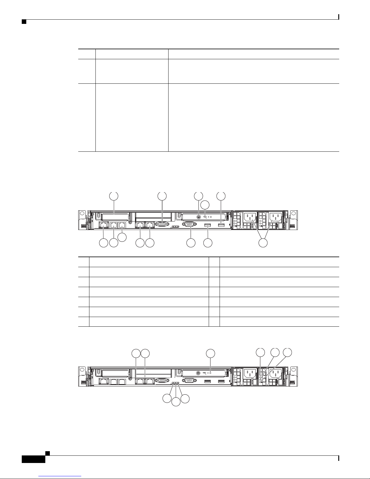
Figure 1-9 Cisco NAC-3355 (With Installed FIPS Card) Rear Panel
Chapter 1 Cisco NAC Appliance Hardware Platforms
Front Locator button/LED Flashing blue = The Locator button has been pressed.
Ethernet interface activity
LEDs (NIC 3 and NIC 4)
Power button with LED Green = The appliance has AC power and is powered up
Green = Activity exists
Flashing green = Activity exists
Off = No activity exists
Rapidly flashing green = The appliance is off and is not yet ready
to be turned on (the appliance typically only remains in this state
for 1 to 3 minutes)
Slowly flashing green = The appliance is currently off and ready to
be turned on
slowly fading on/off green = The appliance is in power-save mode
and is ready to be turned on
Off = The appliance is powered off (AC power disconnected)
1
2
3
4
5
6
7
Figure 1-10 Cisco NAC-3355 (With Installed FIPS Card) Rear Panel LEDs
FIPS card mini-DIN Smart card reader port
FIPS card mode switch
Video port
Empty (unused) PCI slot
Rear USB port 4
Power supply cable sockets
Rear USB port 3
8
Serial port
9
NIC 2 (eth1) GbE interface
10
NIC 1 (eth0) GbE interface
11
NIC 4 (eth3) add-on card
12
NIC 3 (eth2) add-on card
13
Console port
Cisco NAC Appliance Hardware Installation Guide
1-10
OL-20326-01
Page 25

Chapter 1 Cisco NAC Appliance Hardware Platforms
1
FIPS card status LED Solid blue occasionally blinking off = FIPS card is enabled and
2
NIC 1 (eth0) activity LED Green = Activity exists
3
NIC 1 (eth0) link LED Green = Link exists
4
AC power LED Green = AC power source is connected to power supply
5
DC power LED Green = DC power source is connected to power supply
6
Power supply error LED Amber = Power source to power supply is present, but power
7
System error LED Amber = Indicates that a system error has occurred
8
Rear Locator LED Flashing blue = The Front Locator button has been pressed
9
Power LED Green = The appliance has AC power and is powered up
NAC-3315, NAC-3355, and NAC-3395
accepting commands
Two short blue flashes followed by a pause = FIPS card is in
initialization mode
Two longer blue flashes followed by a pause = FIPS card is in
maintenance mode
Repeatedly flashing morse code distress call (. . . - - - . . .)—three
short blue flashes followed by three longer blue flashes followed
again by three more short blue flashes = FIPS card is in error mode
Off = There is no power source connected to the FIPS card
Flashing green = Activity exists
Off = No activity exists
Off = No link exists
Off = No AC power source is connected to power supply
Off = No DC power source is connected to power supply
supply is in error state
Off = Power supply is functioning normally (if AC and DC power
indicators are green) or power supply is disconnected
Off = The system is functioning normally
Rapidly flashing green = The appliance is off and is not yet ready
to be turned on (the appliance typically only remains in this state
for 1 to 3 minutes)
Slowly flashing green = The appliance is currently off and ready
to be turned on
slowly fading on/off green = The appliance is in power-save mode
and is ready to be turned on
Off = The appliance is powered off (power is disconnected)
OL-20326-01
Cisco NAC Appliance Hardware Installation Guide
1-11
Page 26

NAC-3315, NAC-3355, and NAC-3395
Cisco NAC 3395 Series
NAC Manager
1 2 3 4 5 6 7 8
910
13 12 11
195206
CISCO
NAC-3395 Serial Number Location
The serial number label is located at the lower left of the front-panel of the NAC-3355. (See
Figure 1-11.)
Figure 1-11 NAC-3395 Appliance Serial Number Location
XXXXNNNNNNN
Note The serial number for the NAC-3395 is 7 characters long. You can also view the NAC-3315 serial
number location on the Cisco Support website using the Cisco Product Identification Tool. For details,
see Cisco Product Identification Tool, page 1-27.
Chapter 1 Cisco NAC Appliance Hardware Platforms
Cisco NAC 3355 Series
NAC Manager
CISCO
195684
Cisco NAC-3395 Front and Rear Panels
The Cisco NAC-3395 FIPS 140-2 compliant platform provides the enhanced processing, memory, and
power necessary for enterprise wide deployment of the Clean Access Super Manager (Super CAM)
which can support up to 40 Clean Access Servers or 40 HA-CAS pairs. The Cisco NAC-3390 features
dual processors, dual power supplies, 4 GB of RAM, 4 hard disk drives, 4 network interfaces, and an
SSL accelerator card. For additional details, see
Platforms, page 1-1.
Note The Super CAM software is supported only on the Cisco NAC-3395 and Cisco NAC-3390 platforms.
Front Panel Features
Figure 1-12 Cisco NAC-3395 Front Panel
FIPS 140-2 Compliant and Non-FIPS Hardware
1
Hard disk drive (HDD) bay 0
2
Hard disk drive (HDD) bay 2
3
Empty (unused) hard disk drive (HDD) bay
4
Power button with LED indicator (bicolor:
green/amber)
Cisco NAC Appliance Hardware Installation Guide
1-12
8
Front USB port 1
9
Front USB port 2
1
10
CD-ROM/DVD drive
1
11
Empty (unused) hard disk drive (HDD) bay
OL-20326-01
Page 27
Chapter 1 Cisco NAC Appliance Hardware Platforms
Cisco NAC 3395 Series
NAC Manager
CISCO
1
2
3 4 5 6 7
8910
NAC-3315, NAC-3355, and NAC-3395
5
Operator information panel
6
Operator information panel release switch
7
Video port
1. Cisco does not support installing additional hard drives in the NAC-3395 appliance.
Figure 1-13 Cisco NAC-3395 Front Panel LEDs/Buttons
1
HDD activity LED Green = Hard disk drive activity
12
Hard disk drive (HDD) bay 3
13
Hard disk drive (HDD) bay 1
Flashing Green = Hard disk drive activity
Off = Hard disk drive is idle or disabled
2
HDD status LED Amber = Hard disk drive is in error state
Off = Hard disk drive is functioning or disconnected from power
3
Power switch button cover Slides left and right to expose or protect power switch
4
Ethernet icon LED Green = Ethernet interfaces are configured and up
Off = No Ethernet interfaces are currently configured or Ethernet
interfaces are all down
5
Ethernet interface activity
LEDs (NIC 1 and NIC 2)
Green = Activity exists
Flashing green = Activity exists
Off = No activity exists
6
Information LED Amber = A non-critical system event has occurred
Off = System is functioning normally
7
System health LED Off = System health is normal
Amber = A pre-failure system threshold has been breached. This
can be any of the following:
• At least one fan failure (system or processor fan)
• At least one of the temperature sensors reached critical level
(system or processor thermal sensors)
OL-20326-01
• At least one memory module failure
• A power supply unit error has occurred
Cisco NAC Appliance Hardware Installation Guide
1-13
Page 28
NAC-3315, NAC-3355, and NAC-3395
195204
1 2
4
11
12
3 5
9
7
6
1013
8
4 5 6
195205
1 2 3
8
7
9
8
9
10
Rear Panel Features
Figure 1-14 Cisco NAC-3395 (With Installed FIPS Card) Rear Panel
Chapter 1 Cisco NAC Appliance Hardware Platforms
Locator button/LED Flashing blue = The Locator button has been pressed.
Ethernet interface activity
LEDs (NIC 3 and NIC 4)
Power button/LED Green = The appliance has AC power and is powered up
Green = Activity exists
Flashing green = Activity exists
Off = No activity exists
Rapidly flashing green = The appliance is off and is not yet ready
to be turned on (the appliance typically only remains in this state
for 1 to 3 minutes)
Slowly flashing green = The appliance is currently off and ready to
be turned on
slowly fading on/off green = The appliance is in power-save mode
and is ready to be turned on
Off = The appliance is powered off (AC power disconnected)
1
2
3
4
5
6
7
Figure 1-15 Cisco NAC-3395 (With Installed FIPS Card) Rear Panel LEDs
FIPS card mini-DIN Smart card reader port
FIPS card mode switch
Video port
Empty (unused) PCI slot
Rear USB port 4
Power supply cable sockets
Rear USB port 3
8
Serial port
9
NIC 2 (eth1) GbE interface
10
NIC 1 (eth0) GbE interface
11
NIC 4 (eth3) add-on card
12
NIC 3 (eth2) add-on card
13
Console port
Cisco NAC Appliance Hardware Installation Guide
1-14
OL-20326-01
Page 29

Chapter 1 Cisco NAC Appliance Hardware Platforms
1
FIPS card status LED Solid blue occasionally blinking off = FIPS card is enabled and
2
NIC 1 (eth0) activity LED Green = Activity exists
3
NIC 1 (eth0) link LED Green = Link exists
4
AC power LED Green = AC power source is connected to power supply
5
DC power LED Green = DC power source is connected to power supply
6
Power supply error LED Amber = Power source to power supply is present, but power
7
System error LED Amber = Indicates that a system error has occurred
8
Rear Locator LED Flashing blue = The Front Locator button has been pressed
9
Power LED Green = The appliance has AC power and is powered up
NAC-3315, NAC-3355, and NAC-3395
accepting commands
Two short blue flashes followed by a pause = FIPS card is in
initialization mode
Two longer blue flashes followed by a pause = FIPS card is in
maintenance mode
Repeatedly flashing morse code distress call (. . . - - - . . .)—three
short blue flashes followed by three longer blue flashes followed
again by three more short blue flashes = FIPS card is in error mode
Off = There is no power source connected to the FIPS card
Flashing green = Activity exists
Off = No activity exists
Off = No link exists
Off = No AC power source is connected to power supply
Off = No DC power source is connected to power supply
supply is in error state
Off = Power supply is functioning normally (if AC and DC power
indicators are green) or power supply is disconnected
Off = The system is functioning normally
Rapidly flashing green = The appliance is off and is not yet ready
to be turned on (the appliance typically only remains in this state
for 1 to 3 minutes)
Slowly flashing green = The appliance is currently off and ready
to be turned on
slowly fading on/off green = The appliance is in power-save mode
and is ready to be turned on
Off = The appliance is powered off (power is disconnected)
OL-20326-01
Cisco NAC Appliance Hardware Installation Guide
1-15
Page 30

NAC-3310, NAC-3350, and NAC-3390
NAC-3310, NAC-3350, and NAC-3390
Table 1-2 Cisco NAC Appliance Hardware Summary
Cisco NAC
Appliance
NAC-3310
1,2
Product Hardware Specifications Diagrams
MANAGER
Lite Manager
supporting up to 3
standalone or
HA-pair CASs
SERVER
CAS supporting
100, 250, or 500
users
• Single processor: Xeon 2.33 GHz dual core
• 1 GB RAM
• 160 GB NHP SATA HDD
Note Newer Cisco NAC-3310 CAMs/CASs feature a
160GB hard drive, while older NAC-3310s
originally shipped with 80GB hard drives. Both
of these hard drive sizes support High
Availability (HA) deployments, and you can
safely deploy a 160GB model in an HA pair
with an 80GB model.
• 4 10/100/1000 LAN ports [2 Broadcom 5721
integrated NICs; 2 Intel e1000 PCI-X NICs (HP
#NC360T)]
• CD/DVD-ROM Drive
• 4 USB Ports (2 front, 2 rear)
Note The NAC-3310 is based on the HP ProLiant
DL140 G3 server platform.
Chapter 1 Cisco NAC Appliance Hardware Platforms
• Figure 1-16 on
page 1-18 “Cisco
NAC-3310 Front
Panel”
• Figure 1-17 on
page 1-19 “Cisco
NAC-3310 Front
Panel LEDs/Buttons”
• Figure 1-18 on
page 1-20 “Cisco
NAC-3310 Rear
Panel”
• Figure 1-19 on
page 1-20 “Cisco
NAC-3310 Rear
Panel LEDs”
Cisco NAC Appliance Hardware Installation Guide
1-16
OL-20326-01
Page 31

Chapter 1 Cisco NAC Appliance Hardware Platforms
NAC-3310, NAC-3350, and NAC-3390
Table 1-2 Cisco NAC Appliance Hardware Summary (continued)
Cisco NAC
Appliance Product Hardware Specifications Diagrams
NAC-3350
NAC-3390
1. NAC-3310 may require a firmware/BIOS upgrade for HP ProLiant DL140 G3. See Upgrading Firmware, page 2-28.
2. NAC-3310 supports iLO (Lights Out 100i Remote Management). The default iLO “Administrator” account has default username/password:
admin/admin. Defaults can be changed through the BIOS setup.
3. NAC-3350 and NAC-3390 support iLO2 (Integrated Lights Out, version 2). See panel tags for admin account details.
3
3
MANAGER
Standard Manager
supporting up to 20
standalone or
HA-pair CASs
SERVER
CAS supporting
1500, 2500, or
3500 users
MANAGER
Super Manager
supporting up to 40
standalone or
HA-pair CASs
• Single processor: Xeon 3.0 GHz dual core
• Dual power supply
• 2 GB RAM
• 2 x 72 GB SFF SAS RAID HDD
• Smart Array E200i Controller
• 4 10/100/1000 LAN ports [2 Broadcom 5708
integrated NICs; 2 Intel e1000 PCI-X NICs (HP
#NC360T)]
• CD/DVD-ROM Drive
• 4 USB Ports (1 front, 1 internal, 2 rear)
• Cavium CN1120-NHB-E SSL Accelerator Card
Note The NAC-3350 is based on the HP ProLiant
DL360 G5 server platform.
• Dual processor: Xeon 3.0 GHz dual core
• Dual power supply
• 4 GB RAM
• 4 x 72 GB SFF SAS RAID HDD
• Smart Array E200i Controller
• 4 10/100/1000 LAN ports [2 Broadcom 5708
integrated NICs; 2 Intel e1000 PCI-X NICs (HP
#NC360T)]
• CD/DVD-ROM Drive
• 4 USB Ports (1 front, 1 internal, 2 rear)
• Cavium CN1120-NHB-E SSL Accelerator Card
Note The NAC-3390 is based on the HP ProLiant
DL360 G5 server platform.
• Figure 1-20 on
page 1-21 “Cisco
NAC-3350 Front
Panel”
• Figure 1-21 on
page 1-22 “Cisco
NAC-3350 Front
Panel LEDs/Buttons”
• Figure 1-22 on
page 1-23 “Cisco
NAC-3350 Rear
Panel”
• Figure 1-23 on
page 1-23 “Cisco
NAC-3350 Rear
Panel LEDs”
• Figure 1-24 on
page 1-25 “Cisco
NAC-3390 Front
Panel”
• Figure 1-25 on
page 1-25 “Cisco
NAC-3390 Front
Panel LEDs /Buttons”
• Figure 1-26 on
page 1-26 “Cisco
NAC-3390 Rear
Panel”
• Figure 1-27 on
page 1-26 “Cisco
NAC-3390 Rear
Panel LEDs/Buttons”
OL-20326-01
Cisco NAC Appliance Hardware Installation Guide
1-17
Page 32

NAC-3310, NAC-3350, and NAC-3390
1 2 3
4 6
5 7
8 9 8
180955
Cisco NAC-3310 Front and Rear Panels
Note The Cisco NAC-3310 is only FIPS-compliant after you have purchased and installed a field-replaceable
FIPS card as described in the
Guide.
The Cisco NAC-3310 Appliance is the recommended platform for Clean Access Lite Manager and Clean
Access Server (100/250/500 user count) deployments. A NAC-3310 CAM Lite can manage up to 3 Clean
Access Servers or 3 HA-CAS pairs. A NAC-3310 CAS can support 100, 250, or 500 users.
Note If Cisco NAC-3310 has been made FIPS-compliant, then NAC-3310 CAS can support only 250 or 500
users.
The Cisco NAC-3310 comes equipped with 4 network interfaces to provide flexibility in NIC interface
selection and to facilitate CAS high availability configuration.
Cisco NAC Appliance FIPS Card Field-Replaceable Unit Installation
Chapter 1 Cisco NAC Appliance Hardware Platforms
Note Newer Cisco NAC-3310 CAMs/CASs feature a 160GB hard drive, while older NAC-3310s originally
shipped with 80GB hard drives. Both of these hard drive sizes support High Availability (HA)
deployments, and you can safely deploy a 160GB model in an HA pair with an 80GB model.
For additional details, see FIPS 140-2 Compliant and Non-FIPS Hardware Platforms, page 1-1.
Front Panel Features
Figure 1-16 Cisco NAC-3310 Front Panel
1
2
3
4
5
Hard disk drive (HDD) bay
CD-ROM/DVD drive
UID (Unit identification) button with recessed
LED indicator (blue)
System health LED indicator (amber)
Activity/link status LED indicators for NIC 1
(eth0) and NIC2 (eth1) (green)
6
HDD activity LED indicator (green)
7
Power button with LED indicator (bicolor:
green/amber)
8
Thumbscrews for the front bezel
9
Front USB ports
Cisco NAC Appliance Hardware Installation Guide
1-18
OL-20326-01
Page 33

Chapter 1 Cisco NAC Appliance Hardware Platforms
UID
187416
1 2 3 4 5
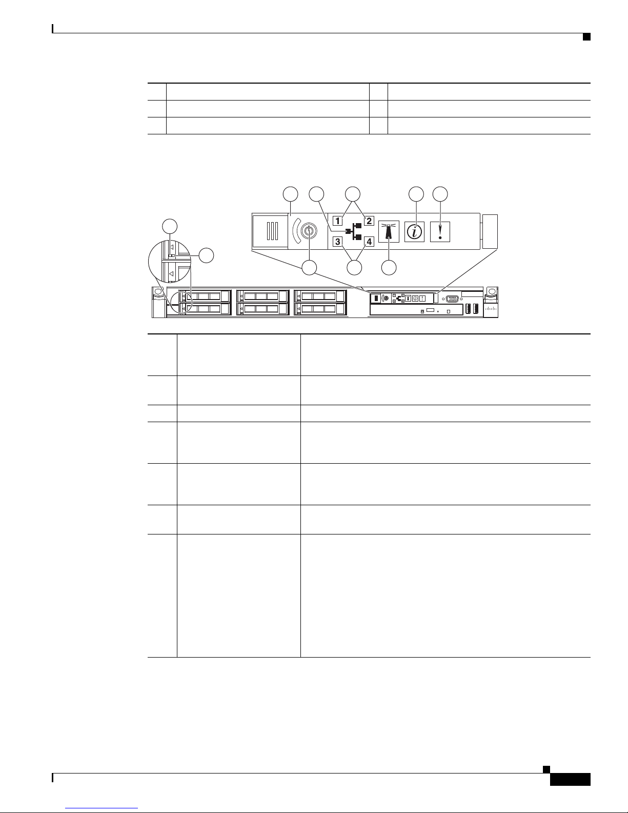
Figure 1-17 Cisco NAC-3310 Front Panel LEDs/Buttons
NAC-3310, NAC-3350, and NAC-3390
1
UID LED (recessed) Blue = A UID button has been pressed.
2
System health LED Off = System health is normal
3
Activity/link status LED
for NIC 1 (eth0) and NIC 2
(eth1)
4
HDD activity LEDs Flashing green = Ongoing drive activity
5
Power status LED
(recessed)
Amber = A pre-failure system threshold has been breached. This
can be any of the following:
• At least one fan failure (system or processor fan)
• At least one of the temperature sensors reached critical level
(system or processor thermal sensors)
• At least one memory module failure
• A power supply unit error has occurred
Solid green = An active network link exists
Flashing green = An ongoing network data activity exists
Off = The server is off-line
Off = No drive activity
Green = The server has AC power and is powered up
Amber = The server has AC power and is in standby mode
Off = The server is powered off (AC power disconnected)
OL-20326-01
Cisco NAC Appliance Hardware Installation Guide
1-19
Page 34

NAC-3310, NAC-3350, and NAC-3390
2 31 6 3 7
151312111098
14
180957
54
1
4 5
3
2
187417
Rear Panel Features
Figure 1-18 Cisco NAC-3310 Rear Panel
Chapter 1 Cisco NAC Appliance Hardware Platforms
1
Ventilation holes
2
Thumbscrew for the top cover
3
Thumbscrews for the PCI riser board
assembly
4
NIC 3 (eth2) and NIC 4 (eth3) PCI Express
GbE LAN (RJ-45) ports (Intel)
5 13
6
Standard height/full-length PCI Express
x16/PCI-X riser board slot cover
7
Power supply cable socket
8
NIC 1 (eth0) and NIC 2 (eth1) integrated GbE
LAN (RJ-45) ports (Broadcom)
Figure 1-19 Cisco NAC-3310 Rear Panel LEDs
9
UID button with recessed LED indicator
(blue)
10
Rear USB ports (black)
11
Video port (blue)
12
Serial port
PS/2 keyboard port (purple)
14
PS/2 mouse port (green)
15
10/100 Mbps iLO LAN port for IPMI
management (RJ-45)
Cisco NAC Appliance Hardware Installation Guide
1-20
OL-20326-01
Page 35

Chapter 1 Cisco NAC Appliance Hardware Platforms
181236
3
1 2 4 5 6
1
NIC activity/link status
LEDs for NIC 1 (eth0) and
NIC 2 (eth1)
2
NIC network speed LEDs Steady amber = The LAN connection is using a GbE link
Solid green = An active network link exists
Flashing green = An ongoing network data activity exists
Off = The server is off-line
Steady green = The LAN connection is using a 100 Mbps link
Off = The LAN connection is using a 10 Mbps link
3
UID LED (recessed) Blue = A UID button has been pressed
4
Link status LED for the
10/100 Mbps LAN port
5
Activity status LED for the
10/100 Mbps LAN port
Green = A network link exists
Off = No network link exists
Flashing green = Network activity exists
Off = No network activity exists
Cisco NAC-3350 Front and Rear Panels
NAC-3310, NAC-3350, and NAC-3390
Note The Cisco NAC-3350 is only FIPS-compliant after you have purchased and installed a field-replaceable
FIPS card as described in the
Guide.
The Cisco NAC-3350 Appliance provides enhanced capability for enterprise wide Clean Access
Standard Manager and Clean Access Server (1500/2500/3500 user count) deployments. A NAC-3350
Standard CAM can manage up to 20 Clean Access Servers or 20 HA-CAS pairs. A NAC-3350 CAS can
support up to 1500, 2500, or 3500 users.
Similar to the Cisco NAC-3310, the Cisco NAC-3350 comes equipped with 4 network interfaces to
provide flexibility in NIC interface selection and facilitate CAS high availability configuration. The
Cisco NAC-3350 additionally provides 2 GB of RAM, two SAS drives configured in RAID 0 and 1, dual
power supplies, and an SSL accelerator card to support large network deployments and provide added
reliability for a centralized CAM/CAS deployment in the network core.
For additional details, see FIPS 140-2 Compliant and Non-FIPS Hardware Platforms, page 1-1.
Front Panel Features
Figure 1-20 Cisco NAC-3350 Front Panel
Cisco NAC Appliance FIPS Card Field-Replaceable Unit Installation
OL-20326-01
Cisco NAC Appliance Hardware Installation Guide
1-21
Page 36

NAC-3310, NAC-3350, and NAC-3390
1 2 3
4
5
6
180960
Chapter 1 Cisco NAC Appliance Hardware Platforms
1
Hard drive bay 1
2
Hard drive bay 2
3
CD-ROM/DVD drive
Figure 1-21 Cisco NAC-3350 Front Panel LEDs/Buttons
1
Power On/Standby button
and system power LED
Green = System is on
Amber = System is shut down, but power is still applied
4
Video connector
5
HP Systems Insight Display
6
USB connector
Off = Power cord is not attached, power supply failure has
occurred, no power supplies are installed; facility power is not
available, or disconnected power button cable
2
UID button/LED Blue = Identification is activated
Flashing blue = System is being managed remotely
Off = Identification is deactivated
3
Internal health LED Green = System health is normal
Amber = System health is degraded. (To identify the component in
a degraded state, refer to “HP Systems Insight Display and LEDs.”)
Red = System health is critical. (To identify the component in a
critical state, refer to “HP Systems Insight Display and LEDs.”)
Off = System health is normal when in standby mode
4
External health LED
(power supply)
Green = Power supply health is normal
Amber = Power redundancy failure occurred
Off = Power supply health is normal when in standby mode
5
NIC 1 (eth0) link/activity
LED
Green = Network link exists
Flashing green = Network link and activity exist
Off = No link to network exists
If power is off, the front panel LED is not active. For status, view
the rear panel LED for the RJ-45 connector (
page 1-23).
6
NIC 2 (eth1) link/activity
LED
Green = Network link exists
Flashing green = Network link and activity exist
Off = No link to network exists
If power is off, the front panel LED is not active. For status, view
the rear panel LED for the RJ-45 connector (
page 1-23).
Figure 1-23 on
Figure 1-23 on
Cisco NAC Appliance Hardware Installation Guide
1-22
OL-20326-01
Page 37

Chapter 1 Cisco NAC Appliance Hardware Platforms
181237
2 3 4 5
67891011121314
1
181238
1 2 7 8 9 10 11 12 13
3 5
4 6
Rear Panel Features
Figure 1-22 Cisco NAC-3350 Rear Panel
NAC-3310, NAC-3350, and NAC-3390
1
NIC 3 (eth2) PCI-X port (Intel)
2
NIC 4 (eth3) PCI-X port (Intel)
3
PCI Express expansion slot 2
4
Power supply bay 1
5
Power supply bay 2
6
Integrated NIC 2 (eth1) port (Broadcom)
7
Integrated NIC 1 (eth0) port (Broadcom)
Figure 1-23 Cisco NAC-3350 Rear Panel LEDs
1
iLO 2 NIC activity LED Green = Activity exists
2
iLO 2 NIC link LED Green = Link exists
3
10/100/1000 NIC 3 (Intel) Activity
LED
4
10/100/1000 NIC 3 (Intel) Link LED Orange = 1000 Mbps
5
10/100/1000 NIC 4 (Intel) Activity
LED
6
10/100/1000 NIC 4 (Intel) Link LED Orange = 1000 Mbps
OL-20326-01
8
Keyboard connector (purple)
9
Mouse connector (green)
10
Video connector (blue)
11
Serial connector
12
USB connector
13
USB connector
14
iLO 2 NIC connector (RJ-45)
Flashing green = Activity exists
Off = No activity exists
Off = No link exists
Steady green = High activity
Flashing green = Activity exists
Off = No activity (if link LED is off, link is dead)
Green = 100 Mbps
Off = 10 Mbps (if activity LED is off, link is dead)
Steady green = High activity
Flashing green = Activity exists
Off = No activity (if link LED is off, link is dead)
Green = 100 Mbps
Off = 10 Mbps (if activity LED is off, link is dead)
Cisco NAC Appliance Hardware Installation Guide
1-23
Page 38

NAC-3310, NAC-3350, and NAC-3390
7
8
9
10
11
12
13
Chapter 1 Cisco NAC Appliance Hardware Platforms
10/100/1000 NIC 1 (Broadcom)
Activity LED
10/100/1000 NIC 1 (Broadcom) Link
LED
10/100/1000 NIC 2 (Broadcom)
Activity LED
10/100/1000 NIC 2 (Broadcom) Link
LED
UID button/LED Blue = Identification is activated
Power supply 1 LED Green = Normal
Power supply 2 LED Green = Normal
Green = Activity exists
Flashing green = Activity exists
Off = No activity exists
Green = Link exists
Off = No link exists
Green = Activity exists
Flashing green = Activity exists
Off = No activity exists
Green = Link exists
Off = No link exists
Flashing blue = System is being managed remotely
Off = Identification is deactivated
Off = System is off or power supply has failed
Off = System is off or power supply has failed
Cisco NAC-3390 Front and Rear Panels
Note The Cisco NAC-3390 is only FIPS-compliant after you have purchased and installed a field-replaceable
FIPS card as described in the
Guide.
The Cisco NAC-3390 Appliance platform provides the enhanced processing, memory, and power
necessary for enterprise wide deployment of the Clean Access Super Manager (Super CAM) which can
support up to 40 Clean Access Servers or 40 HA-CAS pairs. The Cisco NAC-3390 features dual
processors, dual power supplies, 4 GB of RAM, 4 hard disk drives, two integrated NICs, and an SSL
accelerator. For additional details, see
page 1-1.
Note The Super CAM software is supported only on the Cisco NAC-3395 and Cisco NAC-3390 platforms.
Cisco NAC Appliance FIPS Card Field-Replaceable Unit Installation
FIPS 140-2 Compliant and Non-FIPS Hardware Platforms,
Cisco NAC Appliance Hardware Installation Guide
1-24
OL-20326-01
Page 39

Chapter 1 Cisco NAC Appliance Hardware Platforms
180958
5
1 2 3 4 6 7 8
1 2 3
4
5
6
180960
Front Panel Features
Figure 1-24 Cisco NAC-3390 Front Panel
NAC-3310, NAC-3350, and NAC-3390
1
Hard drive bay 1
2
Hard drive bay 2
3
Hard drive bay 3
4
Hard drive bay 4
Figure 1-25 Cisco NAC-3390 Front Panel LEDs /Buttons
1
Power On/Standby button
and system power LED
Green = System is on
Amber = System is shut down, but power is still applied
5
CD-ROM/DVD drive
6
Video connector
7
HP Systems Insight Display
8
USB connector
Off = Power cord is not attached, power supply failure has
occurred, no power supplies are installed; facility power is not
available, or disconnected power button cable
2
UID button/LED Blue = Identification is activated
Flashing blue = System is being managed remotely
Off = Identification is deactivated
3
Internal health LED Green = System health is normal
Amber = System health is degraded. (To identify the component in
a degraded state, refer to “HP Systems Insight Display and
LEDs.”)
Red = System health is critical. (To identify the component in a
critical state, refer to “HP Systems Insight Display and LEDs.”)
Off = System health is normal when in standby mode
OL-20326-01
Cisco NAC Appliance Hardware Installation Guide
1-25
Page 40

NAC-3310, NAC-3350, and NAC-3390
180961
1 2 3 4
5678910111213
180962
1 2 3 4 5 6 7 8 9
4
5
6
Rear Panel Features
Chapter 1 Cisco NAC Appliance Hardware Platforms
External health LED
(power supply)
NIC 1 link/activity LED Green = Network link exists
NIC 2 link/activity LED Green = Network link exists
Green = Power supply health is normal
Amber = Power redundancy failure occurred
Off = Power supply health is normal when in standby mode
Flashing green = Network link and activity exist
Off = No link to network exists
If power is off, the front panel LED is not active. For status, view
the rear panel LED for the RJ-45 connector (
page 1-26)
Flashing green = Network link and activity exist
Off = No link to network exists
If power is off, the front panel LED is not active. For status, view
the rear panel LED for the RJ-45 connector (
page 1-26)
Figure 1-27 on
Figure 1-27 on
Figure 1-26 Cisco NAC-3390 Rear Panel
1
PCI Express expansion slot 1, low-profile,
8
Mouse connector (green)
half-length
2
Cavium SSL Accelerator Card (PCI Express
9
Video connector (blue)
expansion slot 2)
3
Power supply bay 1
4
Power supply bay 2
5
Integrated NIC 2 (eth1) port (Broadcom)
6
Integrated NIC 1 (eth0) port (Broadcom)
7
Keyboard connector (purple)
Figure 1-27 Cisco NAC-3390 Rear Panel LEDs/Buttons
10
Serial connector
11
USB connector
12
USB connector
13
iLO 2 NIC connector (RJ-45)
Cisco NAC Appliance Hardware Installation Guide
1-26
OL-20326-01
Page 41

Chapter 1 Cisco NAC Appliance Hardware Platforms
1
iLO 2 NIC activity LED Green = Activity exists
2
iLO 2 NIC link LED Green = Link exists
3
10/100/1000 NIC 1 Activity LED Green = Activity exists
4
10/100/1000 NIC 1 Link LED Green = Link exists
5
10/100/1000 NIC 2 Activity LED Green = Activity exists
6
10/100/1000 NIC 2 Link LED Green = Link exists
7
UID button/LED Blue = Identification is activated
8
Power supply 1 LED Green = Normal
9
Power supply 2 LED Green = Normal
Cisco Product Identification Tool
Flashing green = Activity exists
Off = No activity exists
Off = No link exists
Flashing green = Activity exists
Off = No activity exists
Off = No link exists
Flashing green = Activity exists
Off = No activity exists
Off = No link exists
Flashing blue = System is being managed remotely
Off = Identification is deactivated
Off = System is off or power supply has failed
Off = System is off or power supply has failed
Cisco Product Identification Tool
The Cisco Product Identification (CPI) tool helps you retrieve the serial number of your Cisco products.
Before you submit a request for service online or by phone, use the CPI tool to locate your product serial
number. You can access this tool from the Cisco Support website.
To access the Cisco Product Identification Tool:
Step 1 Click the Get Tools & Resources link.
Step 2 Click the All Tools (A-Z) tab.
Step 3 Select Cisco Product Identification Tool from the alphabetical drop-down list.
This tool offers three search options:
• Search by product ID or model name.
• Browse for Cisco model.
• Copy and paste the output of the show command to identify the product.
Search results show an illustration of your product with the serial number label location highlighted.
Locate the serial number label on your product and record the information before you place a
service
call.
You can access the CPI tool at:
http://tools.cisco.com/Support/CPI/index.do
OL-20326-01
Cisco NAC Appliance Hardware Installation Guide
1-27
Page 42

Cisco Product Identification Tool
To access the CPI tool, you require a Cisco.com user ID and password. If you have a valid service
contract but do not have a user ID or password, you can register at:
http://tools.cisco.com/RPF/register/register.do
Chapter 1 Cisco NAC Appliance Hardware Platforms
Cisco NAC Appliance Hardware Installation Guide
1-28
OL-20326-01
Page 43

CHAPTER
2
Preparing for Installation
This chapter provides preparatory installation instructions for Cisco NAC Appliance. It provides
instructions for how to verify your hardware and other required equipment, install your Cisco NAC
Appliance in a four-post rack, and upgrade the existing Cisco NAC Appliance software and chassis
firmware.
Note This Installation Guide does not cover the Cisco NAC Network Module (NME-NAC-K9). For
information on Cisco NAC Network Module installation and configuration, see
Cisco NAC Network Modules in Cisco Access Routers.
This chapter covers the following topics:
• Safety Guidelines, page 2-2
• Preparing Your Site for Installation, page 2-6
• Rack-Mounting Your Cisco NAC Appliance CAM/CAS, page 2-14
Getting Started with
• Cisco NAC Appliance Licensing, page 2-26
• Upgrading Cisco NAC Appliance Software, page 2-27
• Upgrading Firmware, page 2-28
OL-20326-01
Cisco NAC Appliance Hardware Installation Guide
2-1
Page 44

Safety Guidelines
Safety Guidelines
Before you begin installing the Cisco NAC Appliance CAM/CAS, review the safety guidelines in this
chapter and
yourself or damaging the equipment.
This section contains:
• General Precautions, page 2-2
• Safety with Equipment, page 2-3
• Safety with Electricity, page 2-3
• Preventing Electrostatic Discharge Damage, page 2-5
• Lifting Guidelines, page 2-5
General Precautions
Observe the following general precautions for using and working with your appliance:
• Observe and follow service markings. Do not service any Cisco product except as explained in your
appliance documentation. Opening or removing covers that are marked with the triangular symbol
with a lightning bolt may expose you to electrical shock. Components inside these compartments
should be serviced only by an authorized service technician.
• If any of the following conditions occur, unplug the product from the electrical outlet and replace
the part, or contact your authorized service provider:
Chapter 2 Preparing for Installation
Rack-Mounting Your Cisco NAC Appliance CAM/CAS, page 2-14 to avoid injuring
–
The power cable, extension cord, or plug is damaged.
–
An object has fallen into the product.
–
The product has been exposed to water.
–
The product has been dropped or damaged.
–
The product does not operate correctly when you follow the operating instructions.
• Keep your appliance away from radiators and heat sources. Also, do not block cooling vents.
• Do not spill food or liquids on your appliance, and never operate the product in a wet environment.
• Do not push any objects into the openings of your appliance. Doing so can cause fire or electric
shock by shorting out interior components.
• Use the product only with other equipment approved by Cisco.
• Allow the product to cool before removing covers or touching internal components.
• Use the correct external power source. Operate the product only from the type of power source
indicated on the electrical ratings label. If you are not sure of the type of power source required,
consult your service representative or local power company.
• Use only approved power cables. If you have not been provided with a power cable for your
appliance or for any AC-powered option intended for your appliance, purchase a power cable that is
approved for use in your country. The power cable must be rated for the product and for the voltage
and current marked on the product’s electrical ratings label. The voltage and current rating of the
cable should be greater than the ratings marked on the product.
Cisco NAC Appliance Hardware Installation Guide
2-2
OL-20326-01
Page 45

Chapter 2 Preparing for Installation
• To help prevent electric shock, plug the appliance and power cables into properly grounded
electrical outlets. These cables are equipped with three-prong plugs to help ensure proper
grounding. Do not use adapter plugs or remove the grounding prong from a cable. If you must use
an extension cord, use a three-wire cord with properly grounded plugs.
• Observe extension cord and power strip ratings. Make sure that the total ampere rating of all
products plugged into the extension cord or power strip does not exceed 80 percent of the extension
cord or power strip ampere ratings limit.
• Do not use appliance, or voltage converters, or kits sold for appliances with your product.
• To help protect your appliance from sudden, transient increases and decreases in electrical power,
use a surge suppressor, line conditioner, or uninterruptible power supply (UPS).
• Position cables and power cords carefully; route cables and the power cord and plug so that they
cannot be stepped on or tripped over. Be sure that nothing rests on your appliance cables or
power
• Do not modify power cables or plugs. Consult a licensed electrician or your power company for site
modifications. Always follow your local or national wiring rules.
Safety Guidelines
cord.
Safety with Equipment
The following guidelines will help ensure your safety and protect the equipment. However, this list does
not include all potentially hazardous situations, so be alert.
Warning
Read the installation instructions before connecting the system to the power source.
• Always disconnect all power cords and interface cables before moving the appliance.
• Never assume that power is disconnected from a circuit; always check.
• Keep the appliance chassis area clear and dust-free before and after installation.
• Keep tools and assembly components away from walk areas where you or others could trip
over
them.
• Do not work alone if potentially hazardous conditions exist.
• Do not perform any action that creates a potential hazard to people or makes the equipment unsafe.
• Do not wear loose clothing that may get caught in the appliance chassis.
• Wear safety glasses when working under conditions that may be hazardous to your eyes.
Safety with Electricity
Statement 1004
Warning
OL-20326-01
This unit is intended for installation in restricted access areas. A restricted access area can be
accessed only through the use of a special tool, lock and key, or other means of security.
Statement 1017
Cisco NAC Appliance Hardware Installation Guide
2-3
Page 46

Safety Guidelines
Chapter 2 Preparing for Installation
Warning
Warning
Warning
Warning
Warning
To avoid electric shock, do not connect safety extra-low voltage (SELV) circuits to telephone-network
voltage (TNV) circuits. LAN ports contain SELV circuits, and WAN ports contain TNV circuits. Some
LAN and WAN ports both use RJ-45 connectors.
Statement 1021
Do not touch the power supply when the power cord is connected. For systems with a power switch,
line voltages are present within the power supply even when the power switch is off and the power
cord is connected. For systems without a power switch, line voltages are present within the power
supply when the power cord is connected.
Statement 4
Before working on equipment that is connected to power lines, remove jewelry (including rings,
necklaces, and watches). Metal objects will heat up when connected to power and ground and can
cause serious burns or weld the metal object to the terminals.
Statement 43
Before working on a chassis or working near power supplies, unplug the power cord on AC units;
disconnect the power at the circuit breaker on DC units.
Statement 12
Do not work on the system or connect or disconnect cables during periods of lightning activity.
Statement 1001
Warning
Warning
This equipment is intended to be grounded. Ensure that the host is connected to earth ground during
normal use.
Statement 39
When installing or replacing the unit, the ground connection must always be made first and
disconnected last.
Statement 1046
Follow these guidelines when working on equipment powered by electricity:
• Locate the room’s emergency power-off switch. Then, if an electrical accident occurs, you can
quickly turn off the power.
• Disconnect all power before doing the following:
–
Working on or near power supplies.
–
Installing or removing an appliance.
–
Performing most hardware upgrades.
• Never install equipment that appears damaged.
• Carefully examine your work area for possible hazards, such as moist floors, ungrounded power
extension cables, and missing safety grounds.
• Never assume that power is disconnected from a circuit; always check.
• Never perform any action that creates a potential hazard to people or makes the equipment unsafe.
• Never work alone when potentially hazardous conditions exist.
Cisco NAC Appliance Hardware Installation Guide
2-4
OL-20326-01
Page 47

Chapter 2 Preparing for Installation
• If an electrical accident occurs, proceed as follows:
–
–
–
–
In addition, use the following guidelines when working with any equipment that is disconnected from a
power source but still connected to telephone wiring or network cabling:
• Never install telephone wiring during a lightning storm.
• Never install telephone jacks in wet locations unless the jack is specifically designed for it.
• Never touch uninsulated telephone wires or terminals unless the telephone line is disconnected at
the network interface.
• Use caution when installing or modifying telephone lines.
Safety Guidelines
Use caution, and do not become a victim yourself.
Turn off power to the appliance.
If possible, send another person to get medical aid. Otherwise, determine the condition of the
victim, and then call for help.
Determine whether the person needs rescue breathing, external cardiac compressions, or other
medical attention; then take appropriate action.
Preventing Electrostatic Discharge Damage
Electrostatic discharge (ESD) can damage equipment and impair electrical circuitry. ESD can occur
when electronic printed circuit cards are improperly handled and can cause complete or intermittent
failures. Always follow ESD-prevention procedures when removing and replacing modules:
• When unpacking a static-sensitive component from its shipping carton, do not remove the
component from the antistatic packing material until you are ready to install the component in your
appliance. Just before unwrapping the antistatic packaging, be sure to discharge static electricity
from your body.
• When transporting a sensitive component, first place it in an antistatic container or packaging.
• Handle all sensitive components in a static-safe area. If possible, use antistatic floor pads and
workbench pads.
• Ensure that the Cisco NAC Appliance CAM/CAS is electrically connected to ground.
• Wear an ESD-preventive wrist strap, ensuring that it makes good skin contact. Connect the clip to
an unpainted surface of the appliance to channel unwanted ESD voltages safely to ground. To guard
against ESD damage and shocks, the wrist strap and cord must operate effectively.
• If no wrist strap is available, ground yourself by touching a metal part of the appliance.
Caution For the safety of your equipment, periodically check the resistance value of the antistatic wrist strap. It
should be between 1 and 10 Mohm.
Lifting Guidelines
A Cisco NAC Appliance CAM/CAS weighs between 15 lb (9.071 kg) and 33 lb (14.96 kg) depending
on what hardware options are installed in the appliance. The appliance is not intended to be moved
frequently. Before you install the appliance, ensure that your site is properly prepared so you can avoid
having to move the appliance later to accommodate power sources and network connections.
Whenever you lift the appliance or any heavy object, follow these guidelines:
OL-20326-01
Cisco NAC Appliance Hardware Installation Guide
2-5
Page 48

Preparing Your Site for Installation
• Always disconnect all external cables before lifting or moving the appliance.
• Ensure that your footing is solid, and balance the weight of the object between your feet.
• Lift the appliance slowly; never move suddenly or twist your body as you lift.
• Keep your back straight and lift with your legs, not your back. If you must bend down to lift the
appliance, bend at the knees, not at the waist, to reduce the strain on your lower back muscles.
• Lift the appliance from the bottom; grasp the underside of the appliance exterior with both hands.
Preparing Your Site for Installation
Before installing a Cisco NAC Appliance CAM/CAS, it is important to prepare the following:
1. Prepare the site (see Site Planning, page 2-6) and review the installation plans or method of
procedures (MOPs).
2. Unpack and inspect the appliance.
3. Gather the tools and test equipment required to properly install the appliance.
This section contains:
• Site Planning, page 2-6
Chapter 2 Preparing for Installation
Site Planning
Warning
• Shipping Package Contents, page 2-10
• Failover Bundles, page 2-11
• Required Equipment, page 2-11
• Configuration Worksheets, page 2-11
This unit is intended for installation in restricted access areas. A restricted access area can be
accessed only through the use of a special tool, lock and key, or other means of security.
Statement 1017
Typically, you should have prepared the installation site beforehand. As part of your preparation, obtain
a floor plan of the site and the equipment rack where the Cisco NAC Appliance CAM/CAS will be
housed. Determine the location of any existing appliances and their interconnections, including
communications and power. Following the airflow guidelines (see
Airflow Guidelines, page 2-9)
ensures that adequate cooling air is provided to the appliance.
All personnel involved in the installation of the appliance, including installers, engineers, and
supervisors, should participate in the preparation of a MOP for approval by the customer. For more
information, see
Method of Procedure, page 2-10.
The following sections provide the site requirement guidelines that you must consider before installing
the
appliance:
• Rack Installation Safety Guidelines, page 2-7
• Site Environment, page 2-8
• Airflow Guidelines, page 2-9
• Temperature and Humidity Guidelines, page 2-9
Cisco NAC Appliance Hardware Installation Guide
2-6
OL-20326-01
Page 49

Chapter 2 Preparing for Installation
• Power Considerations, page 2-9
• Method of Procedure, page 2-10
Rack Installation Safety Guidelines
The Cisco NAC Appliance CAM/CAS can be mounted in most four-post telephone company
(telco-type), 19-inch equipment racks that comply with the Electronics Industries Association (EIA)
standard for equipment racks (EIA-310-D). The distance between the center lines of the mounting holes
on the two mounting posts must be 18.31 inches +/- 0.06 inch (46.50 cm +/- 0.15 cm). The
rack-mounting hardware included with the appliance is suitable for most 19-inch equipment racks or
telco-type frames.
Note Cisco strongly recommends using four-post racks whenever possible, but your rack must have at least
two posts that provide mounting flanges for mounting an appliance.
Figure 2-1 shows a couple of common examples of four-post equipment racks.
Preparing Your Site for Installation
Figure 2-1 Four-Post Equipment Rack Types
1 2
Four-Post (Partially-Enclosed) Rack
Image “1” in Figure 2-1 shows a freestanding, partially-enclosed rack with two mounting posts in the
front and two more at the rear. The Cisco NAC Appliance CAM/CAS may be installed in this type of
enclosed rack, because the appliance only requires an unobstructed flow of cooling air into the front of
the chassis and pushed out of the rear to maintain acceptable operating temperatures for its internal
components.
310199
Four-Post (Open) Rack
Image “2” in Figure 2-1 shows a freestanding, four-post open rack with two mounting posts in front and
two mounting posts at the back. The mounting posts in this type of rack are often adjustable so that you
can position the rack-mounted unit within the depth of the rack rather than flush-mount it with the front
of the rack.
OL-20326-01
Cisco NAC Appliance Hardware Installation Guide
2-7
Page 50

Preparing Your Site for Installation
Site Environment
Chapter 2 Preparing for Installation
Before installing your Cisco NAC Appliance CAM/CAS in a rack, review the following guidelines:
• Two or more people are required to install the appliance in a rack.
• Ensure that the room air temperature is below 95°F (35°C).
• Do not block any air vents; usually, 6 inches (15 cm) of space provides proper airflow.
• Plan the appliance installation starting from the bottom of the rack.
• Do not extend more than one appliance out of the rack at the same time.
• Connect the appliance to a properly grounded outlet.
• Do not overload the power outlet when installing multiple devices in the rack.
• Do not place any object weighing more than 110 lb (50 kg) on top of rack-mounted devices.
The location of your appliance and the layout of your equipment rack or wiring room are extremely
important considerations for proper operation. Equipment placed too close together, inadequate
ventilation, and inaccessible panels can cause malfunctions and shutdowns, and can make maintenance
difficult. Plan for access to front- and rear-panels of the appliance.
The following precautions will help you plan an acceptable operating environment for your appliance
and will help you avoid environmentally caused equipment failures:
• Ensure that the room where your appliance operates has adequate circulation. Electrical equipment
generates heat. Without adequate circulation, ambient air temperature may not cool equipment to
acceptable operating temperatures. For more information, see
• Ensure that the site of the rack includes provisions for source AC power, grounding, and
network
• Allow sufficient space to work around the rack during the installation. You need:
–
–
cables.
At least 3 feet (9.14 m) adjacent to the rack to move, align, and insert the appliance.
At least 24 inches (61 cm) of clearance in front of and behind the appliance for maintenance
Airflow Guidelines, page 2-9.
after installation.
• To mount the appliance between two posts or rails, the usable aperture (the width between the inner
edges of the two mounting flanges) must be at least 17.7 inches (45.0 cm).
Note The rack-mount kit does not include a two-post equipment rack.
• Use appropriate strain-relief methods to protect cables and equipment connections.
• To avoid noise interference in network interface cables, do not route them directly across or along
power
cables.
• Always follow ESD-prevention procedures as described in Preventing Electrostatic Discharge
Damage, page 2-5 to avoid damage to equipment. Damage from static discharge can cause
immediate or intermittent equipment failure.
Cisco NAC Appliance Hardware Installation Guide
2-8
OL-20326-01
Page 51

Chapter 2 Preparing for Installation
Airflow Guidelines
To ensure adequate airflow through the equipment rack, it is recommended that you maintain a clearance
of at least 6 inches (15.24 cm) at the front and the rear of the rack. If airflow through the equipment rack
and the appliances that occupy it is blocked or restricted, or if the ambient air being drawn into the rack
is too warm, an overtemperature condition within the rack and the appliances that occupy it can occur.
The site should also be as dust-free as possible. Dust tends to clog the appliance fans, reducing the flow
of cooling air through the equipment rack and the appliances that occupy it. This reduction increases the
risk of an overtemperature condition.
Additionally, the following guidelines will help you plan your equipment rack configuration:
• Besides airflow, you must allow clearance around the rack for maintenance.
• When mounting an appliance in an open rack, ensure that the rack frame does not block the front
intakes or the rear exhausts.
Temperature and Humidity Guidelines
Table 2-1 lists the operating and non-operating environmental site requirements for the Cisco NAC
Appliance CAM/CAS. The appliance normally operates within the ranges listed; however, a temperature
measurement approaching a minimum or maximum parameter indicates a potential problem. Maintain
normal operation by anticipating and correcting environmental anomalies before they approach critical
values by properly planning and preparing your site before you install the appliance.
Preparing Your Site for Installation
Table 2-1 Operating and Nonoperating Environmental Specifications
Specification Minimum Maximum
Temperature, ambient operating 50°F (10°C) 95°F (35°C)
Temperature, ambient nonoperating and storage -40°F (°C) 158°F (70°C)
Humidity, ambient (noncondensing) operating 10% 90%
Humidity, ambient (noncondensing)
nonoperating and storage
Vibration, operating 5–500 Hz, 2.20 g RMS random —
Power Considerations
You configure the Cisco NAC Appliance CAM/CAS with AC-input power only. Ensure that all power
connections conform to the rules and regulations in the National Electrical Codes (NECs), as well as
local codes. When planning power connections to your appliance, the following precautions and
recommendations must be followed:
• Check the power at your site before installation and periodically after installation to ensure that you
• The AC power supply includes the following features:
5% 95%
are receiving clean power (free of spikes and noise). Install a power conditioner if necessary.
–
Autoselect feature for 110-V or 220-V operation.
–
An electrical cord for all appliances. (A label near the power cord indicates the correct voltage,
frequency, current draw, and power dissipation for the appliance.)
OL-20326-01
Cisco NAC Appliance Hardware Installation Guide
2-9
Page 52

Preparing Your Site for Installation
Chapter 2 Preparing for Installation
Warning
Warning
This product relies on the building’s installation for short-circuit (overcurrent) protection. Ensure that
a fuse or circuit breaker no larger than 120
phase conductors (all current-carrying conductors).
• Install proper grounding to your host equipment rack to avoid damage from lightning and
This equipment must be grounded. Never defeat the ground conductor or operate the equipment in the
absence of a suitably installed ground conductor. Contact the appropriate electrical inspection
authority or an electrician if you are uncertain that suitable grounding is available.
• The AC-input power supply that operates on input voltage and frequency within the ranges of 100
Method of Procedure
As described previously, part of your preparation includes reviewing installation plans or MOPs. An
example of a MOP (a preinstallation checklist of tasks and considerations that need to be addressed and
agreed upon before proceeding with the installation) is as follows:
1. Assign personnel.
2. Determine protection requirements for personnel, equipment, and tools.
3. Evaluate potential hazards that may affect service.
4. Schedule time for installation.
VAC, 15A U.S. (240 VAC, 10A international) is used on the
Statement 13
power
surges.
to 240
VRMS and 50/60 Hz without the need for operator adjustments.
Statement 1024
5. Determine any space requirements.
6. Determine any power requirements.
7. Identify any required procedures or tests.
8. On an equipment plan, make a preliminary decision that locates each Cisco NAC Appliance
CAM/CAS that you plan to install.
9. Read this hardware installation guide.
10. Verify the list of replaceable parts for installation (screws, bolts, washers, and so on) so that the parts
are identified.
11. Check the required tools list to make sure the necessary tools and test equipment are available. For
more information, see
12. Perform the installation.
Shipping Package Contents
Verify the contents of the packing box, shown in Figure 2-2, to ensure that you have received all items
necessary to install your Cisco NAC Appliance. Save the packing material in case you need to repack
the unit. If any item is missing or damaged, contact your Cisco representative or reseller for instructions.
Some Cisco NAC Appliance models might include additional items that are not shown.
Required Equipment, page 2-11.
Cisco NAC Appliance Hardware Installation Guide
2-10
OL-20326-01
Page 53

Chapter 2 Preparing for Installation
Figure 2-2 Shipping Box Contents
Preparing Your Site for Installation
Note Because product software is preloaded onto the Cisco NAC Appliance CAM/CAS, the shipping contents
do not include a separate Cisco NAC Appliance software installation CD. Refer to
NAC Appliance Software, page 2-27 for additional details.
Failover Bundles
If you ordered a Failover Bundle, you will receive two physical Cisco NAC Appliances, and you will
need to perform the initial configuration on each machine as described in this guide. After initial
configuration is complete, configure High Availability (HA) using the CAM or CAS web console and
physically connect the appliances to create the HA pair. Refer to
Availability (HA)”for CAM and CAS HA configuration details.
Cisco NAC Appliance
N
FIPS Smart Card Reader
(FIPS-Compliant Appliances Only)
RJ-45 cable
(straight-through)
Documentation
RJ-45 cable
(crossover; for HA)
AC power cord
Rack mounting kit
Chapter 4, “Configuring High
276749
Upgrading Cisco
Note When connecting high availability (failover) pairs via serial cable, BIOS redirection to the serial port
must be disabled for the Cisco NAC Appliance CAM/CAS. Refer to the
Serial HA (Failover) Connections” section of the Supported Hardware and System Requirements for
Cisco NAC Appliance (Cisco Clean Access) for details.
Required Equipment
You need to supply a workstation (PC or laptop) and keyboard/monitor/mouse to run the Cisco NAC
Appliance Configuration Utility on the appliance. Once the initial configuration is complete, you will
need a standard (straight-through) Ethernet Category 5 network cable with RJ-45 connectors to connect
the interfaces of the Cisco NAC Appliance to the network (eth0 for the CAM; eth0 and eth1 for the CAS).
You will need a crossover RJ-45 Ethernet cable to connect HA-pair appliances together. The
Compliant and Non-FIPS Hardware Platforms, page 1-1 provides interface details for each model.
Configuration Worksheets
You will need the following information to complete the initial configuration of your Cisco NAC
Appliances:
OL-20326-01
“Disable BIOS Redirection for
FIPS 140-2
Cisco NAC Appliance Hardware Installation Guide
2-11
Page 54

Preparing Your Site for Installation
• Clean Access Manager (CAM) Configuration Worksheet
• Clean Access Server (CAS) Configuration Worksheet
• CAS Mode IP Addressing Considerations
Note If planning to configure your appliances for high availability (HA), you first must perform initial
installation on each appliance, then configure HA via the CAM and/or CAS web console(s). You will
need to create a virtual Service IP for the HA-pair via web configuration.
Clean Access Manager (CAM) Configuration Worksheet
Table 2-2 CAM Configuration Utility Worksheet
For Clean Access Manager NAC Appliance
a. IP address for eth0 interface (trusted)
b. Subnet mask (IP netmask) for eth0 interface:
c. Default gateway IP address for eth0 interface:
d. Host name for your CAM:
e. IP address of Domain Name Server on your network:
f. Master secret:
Note The master secret must be the same for
CAMs/CASs deployed as HA peers.
g. Date, time and timezone:
h. To generate the required temporary SSL certificate
(you can change this at a later time):
FQDN or IP address of CAM:
Organization unit (e.g. Sales)
Organization name (e.g. Cisco)
Organization location (e.g. San Jose, CA, US)
1
:
Chapter 2 Preparing for Installation
Note If using FQDN, make sure your DNS server is set
up for the domain name.
i. Root user password:
j. Web console password
1. eth0 and eth1 generally correlate to the first two network cards—NIC 1 and NIC 2—on the server hardware.
2. Cisco highly recommends replacing default password(s) with “strong” passwords (at least 8 characters long, comprised of a
combination of two characters from each of the upper- and lower-case letters, numbers, and special characters categories)
Clean Access Server (CAS) Configuration Worksheet
Table 2-3 CAS Configuration Utility Worksheet
For Clean Access Server NAC Appliance
a. IP address for eth0 interface (trusted)
b. Subnet mask (IP netmask) for eth0 interface:
Cisco NAC Appliance Hardware Installation Guide
2-12
2
:
1
:
OL-20326-01
Page 55

Chapter 2 Preparing for Installation
Table 2-3 CAS Configuration Utility Worksheet
Preparing Your Site for Installation
c. Default gateway IP address for eth0 interface:
d. IP address for eth1 interface (untrusted):
e. Subnet mask (IP netmask) for eth1 interface:
f. Default gateway IP address for eth1 interface
g. Host name for your CAS:
h. IP address of Domain Name Server on your network:
i. Master secret:
Note The master secret must be the same for
1
:
CAMs/CASs deployed as HA peers.
j. Date, time and timezone:
k. To generate the required temporary SSL certificate
(you can change this at a later time):
FQDN or eth0 IP address of CAS:
Organization unit (e.g. Sales)
Organization name (e.g. Cisco)
Organization location (e.g. San Jose, CA, US)
Note If using FQDN, make sure your DNS server is set
up for the domain name.
l. Root user password:
m. Web console password
1. eth0 and eth1 generally correlate to the first two network cards—NIC 1 and NIC 2—on the server hardware.
2. Cisco highly recommends replacing default password(s) with “strong” passwords (at least 8 characters long, comprised of a
combination of two characters from each of the upper- and lower-case letters, numbers, and special characters categories)
2
:
CAS Mode IP Addressing Considerations
Table 2-4 CAS Modes— IP addressing Considerations
CAS Mode Comments
Real-IP • The trusted (eth0) and untrusted (eth1) interfaces of the CAS must be on
different subnets.
• Add static routes on the L3 switch or router to route traffic for the managed
subnets to the trusted interface of the respective CASs.
• If using DHCP relay, make sure the DHCP server has a route back to the
managed subnets.
OL-20326-01
Cisco NAC Appliance Hardware Installation Guide
2-13
Page 56

Rack-Mounting Your Cisco NAC Appliance CAM/CAS
Table 2-4 CAS Modes— IP addressing Considerations (continued)
CAS Mode Comments
Virtual Gateway CAUTION: To avoid switch errors, do not connect the untrusted interface (eth1) of
a Virtual Gateway (IB or OOB) CAS to the switch until after the CAS is added to
the CAM via the web console, and VLAN mapping is configured correctly under
Device Management > CCA Servers > Manage [CAS_IP] > Advanced > VLAN
Mapping. See the
Guide, Release 4.8(3) for details.
• The CAS and CAM must be on different subnets (or VLANs).
• The trusted (eth0) and untrusted interfaces (eth1) of the CAS can have the same
• All end devices in the bridged subnet must be on the CAS untrusted side.
• The CAS is automatically configured for DHCP Passthrough when set to
• Managed subnets must be configured on the CAS for all the user subnets that
• Traffic from clients must pass through the CAS before hitting the gateway.
Chapter 2 Preparing for Installation
Cisco NAC Appliance - Clean Access Server Configuration
IP address. (Note: this is equivalent to an L3 SVI IP address.)
Virtual Gateway mode.
are managed by the CAS. When configuring the Managed subnet, make sure
that you type an unused IP address in that subnet (for the CAS to use), and not
a subnet address.
• When the CAS is an OOB VGW, the following also applies:
CAS interfaces must be on a separate subnet (or VLAN) from the CAM.
The CAS management VLAN must be on a different VLAN than the user or
Access VLANs.
See also “Determining VLANs For Virtual Gateway” in the Cisco NAC Appliance
- Clean Access Server Configuration Guide, Release 4.8(3) for further details.
Rack-Mounting Your Cisco NAC Appliance CAM/CAS
Each Cisco NAC Appliance CAM/CAS has a set of rack handles (installed at the factory). You will use
these handles later when you install the appliance in a four-post rack. You can front (flush) mount or
mid-mount the appliance in a 19-inch (48.3-cm) equipment rack that conforms to the four-post rack
specification (the inside width of the rack should be 17.5 inches [44.45 cm]). Mount the appliance in the
brackets. When the appliance is installed in the rack, it requires one EIA 1.75-inch (4.4-cm) vertical
mounting space or 1 rack unit (RU) for
This section addresses the following two procedures:
• Mounting the NAC-3315 Appliance in a 4-Post Rack, page 2-15
• Mounting the NAC-3355/3395 Appliance in a Four-Post Rack, page 2-21
Caution You must leave clearance in the front and rear of the Cisco NAC Appliance CAM/CAS to allow cooling
air to be drawn in through the front and circulated through the appliance and out the rear of the appliance.
mounting.
The Rack Installation Safety Guidelines, page 2-7 and the following information will help you plan the
equipment rack configuration:
• When mounting an appliance in an equipment rack, ensure that the rack is bolted to the floor.
Cisco NAC Appliance Hardware Installation Guide
2-14
OL-20326-01
Page 57

Chapter 2 Preparing for Installation
• Because you may install more than one appliance in the rack, ensure that the weight of all the
appliances installed does not make the rack unstable.
Caution Some equipment racks are also secured to ceiling brackets due to the weight of the equipment in the rack.
If you use this type of installation, make sure that the rack you are using to install the appliances is
secured to the building structure.
• As mentioned in Airflow Guidelines, page 2-9, maintain a 6-inch (15.2-cm) clearance at the front
and rear of the appliance to ensure adequate air intake and exhaust.
• Avoid installing appliances in an overly congested rack. Air flowing to or from other appliances in
the rack might interfere with the normal flow of cooling air through the appliances, increasing the
potential for overtemperature conditions within the appliances.
• Allow at least 24 inches (61 cm) of clearance at the front and rear of the rack for
appliance
Caution To prevent appliance overheating, never install an appliance in an enclosed rack or a room that is not
properly ventilated or air conditioned.
Rack-Mounting Your Cisco NAC Appliance CAM/CAS
maintenance.
• Follow your local practices for cable management. Ensure that cables to and from appliances do not
impede access for performing equipment maintenance or upgrades.
Note The rack-mount hardware kit does not include a two-post equipment rack.
Mounting the NAC-3315 Appliance in a 4-Post Rack
Warning
NAC-3315 4-Post Rack-Mount Hardware Kit
When the appliance is installed in a rack and is fully extended on its slide rail, it is possible for the
rack to become unstable and tip over, which could cause serious injury. To eliminate the risk of rack
instability from extending the rail or in the event of an earthquake, you should affix the rack to
the floor.
This section contains:
• NAC-3315 4-Post Rack-Mount Hardware Kit, page 2-15
• Installing the NAC-3315 Slide Rails into a Rack, page 2-16
• Installing the NAC-3315 Appliance into the Slide Rails, page 2-19
Figure 2-3 shows the items that you need to install the NAC-3315 appliance in a four-post rack.
OL-20326-01
Cisco NAC Appliance Hardware Installation Guide
2-15
Page 58

Rack-Mounting Your Cisco NAC Appliance CAM/CAS
Figure 2-3 Release Levers on the NAC-3315 Slide Rail Hardware
1 Cable straps (6) 4 M6 screws (6)
2 Slide rail (2) 5 Shipping bracket
3 Front of rail 6 Rear of rail
Chapter 2 Preparing for Installation
Installing the NAC-3315 Slide Rails into a Rack
To install the NAC-3315 appliance in a rack:
Step 1 Press on the rail-adjustment bracket on the rear of the slide rail (see Figure 2-4) to prevent the bracket
from moving.
Step 2 Press on Tab 1 and 2 (see Figure 2-4) and slide the rail-locking carrier toward the front of the slide rail
until it snaps into place.
Step 3 Press on Tab 1 and 2 and slide the rail-locking carrier toward the rear of the slide until it snaps into place.
Cisco NAC Appliance Hardware Installation Guide
2-16
OL-20326-01
Page 59

Chapter 2 Preparing for Installation
Figure 2-4 Installing the Slide Rail into the Rack
Rack-Mounting Your Cisco NAC Appliance CAM/CAS
1 Adjustment tab 1 3 Rail-adjustment bracket
2 Adjustment tab 2
Step 4 If you need to adjust the slide-rail length, lift the release tab (see Figure 2-5) and fully extend the
rail-adjustment bracket from the rear of the slide rail until it snaps into place.
Step 5 Align the pins on the rear rail-locking carrier with the holes on the rear mounting flange. Then, press the
tab (see
Note Ensure that the pins are fully extended through the mounting flange and slide rail.
Figure 2-5) to secure the rear of the slide rail to the rear mounting flange.
OL-20326-01
Cisco NAC Appliance Hardware Installation Guide
2-17
Page 60

Rack-Mounting Your Cisco NAC Appliance CAM/CAS
Figure 2-5 Adjusting the Slide-rail Length
Chapter 2 Preparing for Installation
1 Adjustment tab 3 Pins not extended through the
mounting flange and slide rail
2 Release tab 4 Pins extended through the mounting
flange and slide rail
Step 6 Align the pins (see Figure 2-6) on the front rail-locking carrier to the front mounting flange. If you have
adjusted the rail length, push the rail-locking carrier back toward the rear of the slide rail to align the
slide rail with the mounting flange. Then, press the tab to secure the front of the slide rail to the front
mounting flange.
Note Ensure that the pins are fully extended through the mounting flange and the slide rail.
Step 7 Repeat the steps from 1 to 6 for the other slide rail.
Cisco NAC Appliance Hardware Installation Guide
2-18
OL-20326-01
Page 61

Chapter 2 Preparing for Installation
Figure 2-6 Aligning the Slide Rail with the Mounting Flange
Rack-Mounting Your Cisco NAC Appliance CAM/CAS
1 Adjustment tab 4 Pins extended through the mounting
2 Mounting flange 5 Pins not extended through the
3 Pins
Installing the NAC-3315 Appliance into the Slide Rails
To install the NAC-3315 appliance in the slide rails:
Step 1 Align the CAM/CAS on the slide rails and push the CAM/CAS fully into the rack cabinet.
Step 2 Secure the CAM/CAS to the front mounting flanges with the captive thumbscrews (see Figure 2-7).
Note You must leave the shipping brackets attached to the slide rails unless the shipping brackets
impede the CAM/CAS from sliding fully in the rack cabinet. If you need to remove the shipping
brackets, see Step 3.
flange and slide rail
mounting flange and slide rail
OL-20326-01
Cisco NAC Appliance Hardware Installation Guide
2-19
Page 62

Rack-Mounting Your Cisco NAC Appliance CAM/CAS
Figure 2-7 Aligning the NAC-3315 on the Slide Rails
Chapter 2 Preparing for Installation
1 Shipping brackets 3 Thumbscrews
2 NAC-3315 appliance
Step 3 Press on the release tab (see Figure 2-8) as indicated on the shipping bracket, and remove the shipping
bracket from the slide rail.
Step 4 Repeat step 3 for the other shipping bracket. Store the shipping brackets for future use.
Note You must reinstall the shipping brackets on the slide rails before you transport the rack cabinet with the
CAM/CAS installed. To reinstall the shipping brackets, reverse the steps.
Cisco NAC Appliance Hardware Installation Guide
2-20
OL-20326-01
Page 63

Chapter 2 Preparing for Installation
Figure 2-8 Removing the Shipping Brackets
Rack-Mounting Your Cisco NAC Appliance CAM/CAS
1 Release tab
Mounting the NAC-3355/3395 Appliance in a Four-Post Rack
Warning
When the appliance is installed in a rack and is fully extended on its slide rail, it is possible for the
rack to become unstable and tip over, which could cause serious injury. To eliminate the risk of rack
instability from extending the rail or in the event of an earthquake, you should affix the rack to
the floor.
This section contains:
• NAC-3355/3395 4-Post Rack-Mount Hardware Kit, page 2-22
• Installing the NAC-3355/3395 Slide Rails Into the 4-Post Rack, page 2-22
• Installing the NAC-3355/3395 Appliance Into the Slide Rails, page 2-25
OL-20326-01
Cisco NAC Appliance Hardware Installation Guide
2-21
Page 64

Rack-Mounting Your Cisco NAC Appliance CAM/CAS
NAC-3355/3395 4-Post Rack-Mount Hardware Kit
Figure 2-9 shows the items that you need to install the NAC-3355/3395 appliance in a 4-post rack.
Figure 2-9 NAC-3355/3395 Rack Installation Kit Contents
Chapter 2 Preparing for Installation
Cable-management
arm stop bracket
Cable-management
support arm
EIA latches
(2)
Front of rails
Cable-management
arm mounting bracket
(Not used)
Cable-management
arm assembly
10-32 screws
(13)
12-24 screws
(13)
Slide rail
(left)
M6 screws
(13)
Slide rail
Cage nuts
Clip nuts
(13)
(right)
Large
cable tie
(1)
Cable ties
(5)
(13)
253136
Note Some of the items in Figure 2-9 are shipped in the NAC-3355/3395 shipping container, not necessarily
with the rack installation kit.
Installing the NAC-3355/3395 Slide Rails Into the 4-Post Rack
When installing the NAC-3355/3395 slide rails in your equipment rack, Cisco recommends using cage
nuts with square-holed racks, clip nuts with round-holed racks, and your own rack screws with
thread-hole racks.
Note If the slide rails that arrived in your shipping container include shipping thumbscrews, remove them
before performing the following procedure.
Step 1 Identify an available space in your rack to install the NAC-3355/3395.
Step 2 If you have either a round-holed or square-holed rack, install cage nuts or clip nuts, in the middle and
bottom holes of the rack unit space on each side of the rack your NAC-3355/3395 will occupy (see
Figure 2-10).
Step 3 Install cage nuts or clip nuts in the top and bottom holes for each side of the respective rear rack
mounting rails (see
Cisco NAC Appliance Hardware Installation Guide
2-22
Figure 2-10).
OL-20326-01
Page 65

Chapter 2 Preparing for Installation
Cage
nuts
Front Rear
Clip
nuts
Front Rear
253138
Figure 2-10 Position Cage Nuts or Clip Nuts
Rack-Mounting Your Cisco NAC Appliance CAM/CAS
Front Rear
Upper U
(For 2 U
system)
Lower U
Optional screw
to secure system
into the rack
Clip or
cage nuts
253137
Step 4 Use a screwdriver to install the cage nuts or clip nuts on the inside of the mounting rail, as required for
your particular rack, into the selected holes (see
Figure 2-11).
Figure 2-11 Install Cage Nuts or Clip Nuts
Step 5 Use the tab on the rear of the slide rails to align the rear of the slide rail to the rear of the four-post rack.
Step 6 Select the best range among Posts A, B, C, and D to fit into the slots. Adjust the length of the slide rails
by moving around the depth adjustment screws and nuts (see
Step 7 Once you have the combination and fit you want for your NAC-3355/3395, reinstall and tighten the
screws and nuts for both slide rails.
OL-20326-01
Figure 2-12).
Cisco NAC Appliance Hardware Installation Guide
2-23
Page 66

Rack-Mounting Your Cisco NAC Appliance CAM/CAS
Post A
Post B
Post C
Post D
Slots
253139
253143
Figure 2-12 Set Up Slide Rails
Step 8 Fasten the front of the slide rail and EIA latch to the front of the four-post rack by installing a screw in
the bottom hole of the selected rack space for your NAC-3355/3395. Then, install another screw in the
middle hole to secure the front of the slide rail to the four-post rack (see
Note Use the 12-24 screws that came in the rack installation kit if you have installed clip nuts or cage nuts in
the four-post rack mounting rails.
Chapter 2 Preparing for Installation
Figure 2-13).
Figure 2-13 Fasten Front of Slide Rail to Four-Post Rack
Step 9 Use two screws to fasten the rear of the slide rail to the respective rear mounting rail of the four-post
rack in the upper and bottom holes of the selected rack space for your NAC-3355/3395 (see
Figure 2-14).
Cisco NAC Appliance Hardware Installation Guide
2-24
OL-20326-01
Page 67

Chapter 2 Preparing for Installation
253144
253145
3
4
2
1
5
Figure 2-14 Fasten Rear of Slide Rail to Four-Post Rack
Step 10 Repeat Step 8 and Step 9 to attach the other slide rail to the selected rack space for your
NAC-3355/3395.
Rack-Mounting Your Cisco NAC Appliance CAM/CAS
Installing the NAC-3355/3395 Appliance Into the Slide Rails
Step 1 Extend the slide rails forward out of the four-post rack until they click (twice) into place.
Step 2 Carefully lift the NAC-3355/3395 and tilt it into position over the slide rails so that the rear chassis nail
heads on the CAM/CAS line up with the rear slots on the slide rails (see
Step 3 Slide the CAM/CAS down so that the rear chassis nail heads slip into the two rear slots, and then slowly
lower the front of the CAM/CAS until the other chassis nail heads slip into their respective slots on the
slide rails.
Note Ensure that the front latch slides over the chassis nail heads.
Figure 2-15 Position the NAC-3355/3395 In the Slide Rails
Figure 2-15).
OL-20326-01
Cisco NAC Appliance Hardware Installation Guide
2-25
Page 68

Cisco NAC Appliance Licensing
1 Extend the slide rails forward 4 Lower the CAM/CAS into position
2 Chassis nail heads 5 Front latches
3 Rear slide rail slots
Step 4 Lift the locking levers on the slide rails and push the CAM/CAS all the way into the rack until it clicks
into place (see
Figure 2-16 Push the NAC-3355/3395 Into the Rack
Chapter 2 Preparing for Installation
Figure 2-16).
1
1 Locking levers 2 Push the CAM/CAS into the rack
Cisco NAC Appliance Licensing
You need at least one Clean Access Manager license and one Clean Access Server license for your Cisco
NAC Appliance system to work. Both licenses are installed via the Clean Access Manager
administration web console. For Out-of-Band (OOB) deployments, you must add both the OOB CAS
license and the CAS as an Out-of-Band device to the CAM to access the OOB Management module of
the CAM web console.
• For instructions on how to obtain new license(s) for your system, see Cisco NAC Appliance Service
Contract/Licensing Support.
• For instructions on how to install licenses for your system (after initial configuration is complete),
see
Install CAM License, page 3-13 and Add Additional Licenses, page 3-15.
2
253146
Cisco NAC Appliance Hardware Installation Guide
2-26
OL-20326-01
Page 69

Chapter 2 Preparing for Installation
Upgrading Cisco NAC Appliance Software
Note This Installation Guide does not cover the Cisco NAC Network Module (NME-NAC-K9). For
information on Cisco NAC Network Module installation and configuration, see
Cisco NAC Network Modules in Cisco Access Routers.
Cisco NAC Appliance CAMs/CASs are preloaded with a default version of the Cisco NAC Appliance
software, which may not match the latest release image. Cisco recommends you always run the latest
supported version of the system software to ensure you have the latest product enhancements and fixes.
You can install Cisco NAC Appliance Release 4.8(x) only on the following Cisco NAC Appliance
platforms:
• NAC-3315, NAC-3355, and NAC-3395
• NAC-3310, NAC-3350, and NAC-3390
• Cisco NAC Network Module (NME-NAC-K9)
In addition to the above, you can install Cisco NAC Appliance Release 4.8 on CCA-3140 (EOL).
Upgrading Cisco NAC Appliance Software
Getting Started with
Note Due to limited hardware resources on the CCA-3140, some combinations of Release 4.8 features may
cause undesirable system behavior. If you are experiencing problems with Release 4.8 on the CCA-3140,
please contact the Cisco Technical Assistance Center (TAC).
Note The support for CCA-3140 has been dropped starting from Cisco NAC Appliance release 4.8(1).
Upgrading to Release 4.8(x)
In Cisco NAC Appliance release 4.8(x), you use a .tar.gz upgrade process similar to that used for
upgrading CAM/CAS appliances in Cisco NAC Appliance Release 4.7(2) and 4.6(1). (Cisco NAC
Appliance release 4.7(0) and 4.7(1) requires users to perform “in-place” upgrades via an .ISO image on
a CD-ROM.)
To upgrade to Release 4.8(x), follow the appropriate upgrade instructions in the “Upgrading” section of
the
Release Notes for Cisco NAC Appliance corresponding to your latest Cisco NAC Appliance release
version.
Note You cannot use the Release 4.8(x) .ISO CD-ROM to perform an upgrade. You must use the .tar.gz
upgrade file method.
Note You must upgrade the CAM first prior to upgrading the CAS. Otherwise, you will end up in a situation
in which CAS has been upgraded but not the CAM.
OL-20326-01
Cisco NAC Appliance Hardware Installation Guide
2-27
Page 70

Upgrading Firmware
Downloading Cisco NAC Appliance Software
You can access the latest versions of the Cisco NAC Appliance Release 4.8(x) installation .ISO file as
follows.
Caution Before downloading or installing any Cisco NAC Appliance software, make sure to refer to the Release
Notes for Cisco NAC Appliance, corresponding to your latest Cisco NAC Appliance release version, to
understand the enhancements, caveats, and upgrade impact to your existing deployment.
Step 1 Log in to the Cisco Software Download Site at http://www.cisco.com/public/sw-center/index.shtml. You
will likely be required to provide your CCO credentials.
Step 2 Navigate to Security > Endpoint Security > Cisco Network Access Control > Cisco NAC Appliance
> Cisco NAC Appliance 4.8.
Step 3 Download the latest 4.8(x) .ISO image (e.g. nac-4.8-K9.iso) and burn the image as a bootable disk to a
CD-R.
Chapter 2 Preparing for Installation
Note Cisco recommends burning the .ISO image to a CD-R using speeds 10x or lower. Higher speeds can
result in corrupted/unbootable installation CDs.
Upgrading Firmware
Cisco NAC Appliance CAMs/CASs are subject to any system BIOS/Firmware upgrades required for the
server model on which they are based.
• The NAC-3315 is based on the IBM System x3250 M2 server platform and the NAC-3355/3395 are
based on the IBM System x3550 M2 server platform.
• The NAC-3310 is based on the HP ProLiant DL140 G3 server platform and the NAC-3350/3390 are
based on the HP ProLiant DL360 G5 server platform.
Note For Cisco NAC-3310 platforms, be sure to also refer to the “DL140 G3 Required BIOS/Firmware
Upgrades” section of the Supported Hardware and System Requirements for Cisco NAC Appliance
(Cisco Clean Access) for further details.
Cisco NAC Appliance Hardware Installation Guide
2-28
OL-20326-01
Page 71

CHAPTER
3
Installing the Clean Access Manager and Clean
Access Server
This chapter covers the following topics:
• Overview, page 3-1
• Installing the Clean Access Manager, page 3-2
• Installing the Clean Access Server, page 3-18
• Cisco NAC Appliance Connectivity Across a Firewall, page 3-34
• Connectivity Across a Wide Area Network, page 3-37
• Configuring Additional NIC Cards, page 3-37
• Serial Connection to the CAM and CAS, page 3-39
• Useful CLI Commands for the CAM/CAS, page 3-42
• Manually Restarting the CAM/CAS Configuration Utility, page 3-46
• Troubleshooting the Installation, page 3-47
Overview
OL-20326-01
• Powering Down the NAC Appliance, page 3-50
This chapter provides installation instructions for Cisco NAC Appliance. It provides instructions for
how to initially configure your CAM and CAS using the Configuration Utility, access the CAM web
console, and install product licenses. Once the initial configuration of your CAM and CAS is complete,
you will be able to access the CAM web console to continue the rest of the configuration for your
deployment.
For comprehensive configuration information, refer to the latest Cisco NAC Appliance - Clean Access
Manager Configuration Guide, Release 4.8(3) and Cisco NAC Appliance - Clean Access Server
Configuration Guide, Release 4.8(3) documents available on Cisco.com under
http://www.cisco.com/en/US/products/ps6128/products_installation_and_configuration_guides_list.ht
ml. When using the online publications, make sure to refer to the documents that match the software
version running on your Cisco NAC Appliance (e.g. “Release 4.8”).
Cisco NAC Appliance Hardware Installation Guide
3-1
Page 72

Chapter 3 Installing the Clean Access Manager and Clean Access Server
Installing the Clean Access Manager
Important Release Information
Refer to the Release Notes for Cisco NAC Appliance corresponding to your latest Cisco NAC Appliance
release version, for additional and late-breaking information on 4.8(x) software releases.
Installing the Clean Access Manager
This section describes how to install the Clean Access Manager. Topics include:
• Overview, page 3-2
• Summary of Steps For New Installation, page 3-3
• Connect the Clean Access Manager, page 3-4
• Install the Clean Access Manager (CAM) Software from CD-ROM, page 3-5
• Perform the Initial CAM Configuration, page 3-6
• Access the CAM Web Console, page 3-11
Overview
The Cisco NAC Appliance CAM/CAS hardware platforms are Linux-based network hardware
appliances which are pre-installed with either the CAM (MANAGER) or CAS (SERVER) application,
the operating system, and all relevant components on a dedicated server machine. In Release 4.7(0) and
later, the operating system comprises a hardened Linux kernel based on CentOS 5.3. Cisco NAC
Appliance does not support the installation of any other packages or applications onto a CAM or CAS
dedicated machine.
When you receive a new Cisco NAC Appliance, you will need to connect to the appliance and perform
initial configuration.
If you want to install a different version of the software than what is shipped on the appliance, you can
perform software installation via CD first. Refer to
Cisco NAC Appliance (Cisco Clean Access) for details on the software versions supported on Cisco NAC
Appliance CAM/CAS platforms.
This chapter contains information for performing CD software installation and initial configuration of a
Clean Access Manager.
With Cisco NAC Appliance software installation via CD, you must select whether to install the Clean
Access Manager or Clean Access Server application. Once the CAM or CAS is installed on the dedicated
appliance (application, OS, and relevant components), the installation of any other packages or
applications on the CAM or CAS is not supported.
Note Static IP addresses must be configured for the CAM/CAS interfaces. DHCP mode is not supported for
configuration of these interfaces.
Supported Hardware and System Requirements for
Note For installation details on the Cisco NAC Network Module (CAS on a network module), refer to Getting
Started with Cisco NAC Network Modules in Cisco Access Routers.
Cisco NAC Appliance Hardware Installation Guide
3-2
OL-20326-01
Page 73

Chapter 3 Installing the Clean Access Manager and Clean Access Server
Summary of Steps For New Installation
Note If relevant, back up your current Clean Access Manager configuration and save the snapshot to your
local computer for safekeeping as described in the
Configuration Guide, Release 4.8(3).
Step 1 Follow the instructions on your welcome letter to obtain a valid license file for your installation. Refer
to the instructions in
evaluating Cisco NAC Appliance, visit http://www.cisco.com/go/license/public to obtain an evaluation
license.)
When you add the initial CAM license, the top of the CAM web console will display the type of Clean
Access Manager license installed:
• Cisco Clean Access Lite Manager supports 3 Clean Access Servers
• Cisco Clean Access Standard Manager supports 20 Clean Access Servers
• Cisco Clean Access Super Manager supports 40 Clean Access Servers
(SuperCAM runs only on the NAC-3390 platform)
Cisco NAC Appliance Service Contract/Licensing Support for details. (If you are
Installing the Clean Access Manager
Cisco NAC Appliance - Clean Access Manager
Additionally, the Administration > CCA Manager > Licensing page will display the types of licenses
present after they are added. See
Step 2 Obtain a bootable CD of the latest version of the software. You can log in and download the latest 4.8(x)
.ISO image from Cisco Software Download Site at
Install CAM License, page 3-13 for further details.
http://www.cisco.com/public/sw-center/index.shtml,
or click the “Download Software” link from the Cisco NAC Appliance support page here and burn it as
a bootable disk to a CD-R.
Note Cisco recommends burning the .ISO image to a CD-R using speeds 10x or lower. Higher speeds
can result in corrupted/unbootable installation CDs.
Step 3 Connect the CAM to the network and connect a monitor and keyboard to the CAM, or connect your
workstation to the CAM via serial cable, as described in
Step 4 Install the software as described in Install the Clean Access Manager (CAM) Software from CD-ROM,
Connect the Clean Access Manager, page 3-4.
page 3-5.
Note If your NAC-3310 appliance does not read the software on the CD ROM drive and instead
attempts to boot from the hard disk, before proceeding you will need to change the appliance
settings to boot from CD ROM as described in
Configuring Boot Settings on the Cisco NAC
Appliance CAM/CAS, page 3-40.
Step 5 Perform the initial configuration of the CAM, as described in Perform the Initial CAM Configuration,
page 3-6.
Note For High Availability mode, install and initially configure each CAM first before configuring HA. Refer
to Installing a Clean Access Manager High Availability Pair, page 4-3 for details.
You must use identical appliances (e.g. NAC-3350 and NAC-3350) in order to configure High
Availability (HA) pairs of Clean Access Managers (CAMs) or Clean Access Servers (CASs).
OL-20326-01
Cisco NAC Appliance Hardware Installation Guide
3-3
Page 74

Installing the Clean Access Manager
Step 6 Access the CAM web console and install a valid FlexLM license file for the Clean Access Manager as
described in
Step 7 In the web console, navigate to Administration > CCA Manager > Licensing to install any additional
Access the CAM Web Console, page 3-11.
FlexLM license files for your Clean Access Servers, as described in
Step 8 Add your Clean Access Server(s) to the Clean Access Manager, as described in the Cisco NAC Appliance
- Clean Access Manager Configuration Guide, Release 4.8(3).
Connect the Clean Access Manager
To install the Clean Access Manager software from CD-ROM or to perform its initial configuration, you
will need to connect the target machine and access the CAM’s command line.
Step 1 The Clean Access Manager requires one of the two 10/100/1000BASE-TX interface connectors on the
back panel of the CAM for its eth0 network interface. Connect the NIC1 network interface on the target
machine to your local area network (LAN) using a CAT5 Ethernet cable.
Step 2 Connect the power by plugging one end of the AC power cord into the back of the machine and the other
end into an electrical outlet.
Chapter 3 Installing the Clean Access Manager and Clean Access Server
Install CAM License, page 3-13.
Step 3 Connect the external FIPS Smart card reader module to a FIPS 140-2 compliant NAC-3315, NAC-3355,
or NAC-3395 by plugging the Smart card reader mini-DIN cable into the female mini-DIN FIPS card
port on the back of the appliance (see
Figure 1-4 on page 1-6, Figure 1-9 on page 1-10, and Figure 1-14
on page 1-14). (Ensure you also have a Smart card inserted into the reader.)
Step 4 Power on the CAM by pressing the power button on the front of the machine. The diagnostic LEDs will
flash a few times as part of an LED diagnostic test. Status messages are displayed on the console as the
CAM boots up.
Step 5 Access the CAM’s command line by either:
• Connecting a monitor and keyboard directly to the CAM via the keyboard connector and video
monitor/console connector on the back panel.
• Connecting a serial cable from an external workstation (PC/laptop) to the CAM and open a serial
connection using terminal emulation software (such as HyperTerminal or SecureCRT) on the
external workstation, as described in
Note Cisco NAC Appliances assume the keyboard connected to be of US layout for both direct and IP-KVM
Serial Connection to the CAM and CAS, page 3-39.
connections. Use a US layout keyboard or ensure that you know the key mapping if you are connecting
a keyboard of different layout.
Note The eth1 interface (NIC2) of the CAM is only required when connecting High Availability CAM pairs.
Note Static IP addresses must be configured for the CAM/CAS interfaces. DHCP mode is not supported for
configuration of these interfaces.
Cisco NAC Appliance Hardware Installation Guide
3-4
OL-20326-01
Page 75

Chapter 3 Installing the Clean Access Manager and Clean Access Server
Installing the Clean Access Manager
Install the Clean Access Manager (CAM) Software from CD-ROM
The following steps describe how to perform optional CD installation of the Clean Access Manager
software on the NAC-3310/3315 MANAGER, NAC-3350/3355 MANAGER, and NAC-3390/3395
MANAGER appliances.
Step 1 Connect the target installation machine to the network and access the command line of the machine by
direct console or over a serial connection, as described in
page 3-39.
Step 2 Download the latest software version supported on the target machine as follows:
a. Log in to the Cisco Software Download Site at http://www.cisco.com/public/sw-center/index.shtml.
You will likely be required to provide your CCO credentials.
b. Navigate to Security > Endpoint Security > Cisco Network Access Control > Cisco NAC
Appliance > Cisco NAC Appliance 4.8.
c. Download the latest 4.8(x) .ISO image (e.g. nac-4.8_3-K9.iso) and burn the image as a bootable
disk to a CD-R.
Serial Connection to the CAM and CAS,
Note Cisco recommends burning the .ISO image to a CD-R using speeds 10x or lower. Higher
speeds can result in corrupted/unbootable installation CDs.
Step 3 Insert the CD-ROM containing the Cisco NAC Appliance .ISO file into the CD-ROM drive and reboot
the machine.
Step 4 The Cisco Clean Access Installer welcome screen appears after the machine restarts:
Cisco Clean Access 4.8.3 Installer (C) 2012 Cisco Systems, Inc.
Welcome to the Cisco Clean Access Installer!
- To install a Cisco Clean Access device, press the <ENTER> key.
- To install a Cisco Clean Access device over a serial console, enter serial a
t the boot prompt and press the <ENTER> key.
boot:
Step 5 At the “boot:” prompt, type one of the following options depending on the type of connection:
• Press the Enter key if your monitor and keyboard are directly connected to the appliance.
• Type serial and press enter in the terminal emulation console if you are accessing the appliance
over a serial connection.
Step 6 If the install CD detects an existing installation of Cisco NAC Appliance, you are presented with the
following prompt:
Checking for existing installations.
Clean Access Manager 4.8.0 installation detected.
Please choose one of the following actions:
1) Install.
2) Exit.
Step 7 Choose 1 to perform a fresh installation of the Cisco NAC Appliance software.
OL-20326-01
Cisco NAC Appliance Hardware Installation Guide
3-5
Page 76

Installing the Clean Access Manager
Step 8 Next, the Cisco NAC Appliance software installer asks you to specify whether you are installing a Clean
Access Manager or Clean Access Server. At the following prompt, enter
a Clean Access Manager.
Please choose one of the following configurations:
1) CCA Manager.
2) CCA Server.
3) Exit.
Caution Only one CD is used for installation of the Clean Access Manager or Clean Access Server software. You
must select the appropriate type, either CAM or CAS, for the target machine on which you are
performing installation.
Step 9 The Clean Access Manager Package Installation then executes. The installation takes several minutes.
When finished, the installation script presents the following message, prompting you to press Enter to
reboot the CAM and launch the Clean Access Manager quick configuration utility.
Installation complete. Press <ENTER> to continue
After you press Enter, the welcome screen for the Clean Access Manager quick configuration utility
appears, and a series of questions prompt you for the initial configuration, as described in
Initial CAM Configuration, next.
Chapter 3 Installing the Clean Access Manager and Clean Access Server
1 to perform the installation for
Perform the
Perform the Initial CAM Configuration
When installing the Clean Access Manager from CD-ROM, the Configuration Utility Script
automatically appears after the software packages install to prompt you for the initial configuration.
Note If necessary, you can always manually start the Configuration Utility Script as follows:
1. Over a serial connection or working directly on the CAM, log onto the CAM as user root with
correct password.
2. Run the initial configuration script by entering the following command:
service perfigo config
You can run the service perfigo config command to modify the configuration of the CAM if it cannot
be reached through the web admin console. For further details on CLI commands, see
Commands, page 3-42.
Configuration Utility Script
The configuration utility script suggests default values for particular parameters. To configure the
installation, either accept the default value or provide a new one, as described below.
Step 1 After the software is installed from the CD and package installation is complete, the welcome script for
the configuration utility appears:
Welcome to the Cisco Clean Access Manager quick configuration utility.
CAM CLI
Cisco NAC Appliance Hardware Installation Guide
3-6
OL-20326-01
Page 77

Chapter 3 Installing the Clean Access Manager and Clean Access Server
Note that you need to be root to execute this utility.
The utility will now ask you a series of configuration questions.
Please answer them carefully.
Cisco Clean Access Manager, (C) 2012 Cisco Systems, Inc.
Note If this prompt does not appear after you install the Cisco NAC Appliance software and restart the CAM,
refer to Manually Restarting the CAM/CAS Configuration Utility, page 3-46.
Step 2 If your CAM is a FIPS-compliant platform (NAC-3315, NAC-3355, or NAC-3395) the first prompt asks
if you want to initialize the on-board FIPS card (used to ensure FIPS compliant functions on the
appliance). Otherwise, skip to
Do you want to initialize the fips cards? (y/n)? [y]
Step 3 Choose y to enable FIPS on your appliance. The appliance automatically initializes the FIPS card and
Step 6.
attempts to establish the security world.
-- Running startup script 45drivers
-- Running startup script 46exard
Installing the Clean Access Manager
-- Running startup script 50hardserver
Security world not found
Creating the security world and initializing the smart cards
Next, the FIPS setup process prompts you to specify how many Smart Cards (from 1-6) you
want to initialize to enable FIPS compliance on the CAM.
How many cards do you want to initialize (1-6)? [1]
Set ncipher card switch in i mode and press Return to continue
Step 4 Enter the number of Smart Cards you want to initialize, ensure that the FIPS card operation switch on
the back of the CAM is switched to “I” (for “initialize”), and press Return.
Module 1, command ClearUnit: OK
Create Security World:
Module 1: 0 cards of 1 written
Module 1 slot 0: unknown card
Module 1 slot 0: - no passphrase specified - overwriting card
Module #1 Slot #0: Processing ...
Card writing complete.
security world generated on module #1; hknso = 909bd9f06542521a01f42fc881c8abcba
b0812ee
Set ncipher card switch in o mode and press Return to continue
Step 5 Switch the FIPS card switch back to “O” (for “operational”) and press Return.
Module 1, command ClearUnit: OK
Card(s) check passed
Do you want to continue with the rest of the NAC Manager Configuration? (y/n)? [y]
Step 6 When prompted, enter an IP address for the eth0 (trusted) interface of the CAM.
Configuring the network interface:
Please enter the IP address for the interface eth0 []: 10.201.240.11
OL-20326-01
Cisco NAC Appliance Hardware Installation Guide
3-7
Page 78

Installing the Clean Access Manager
You entered 10.201.240.11 Is this correct? (y/n)? [y]
At the prompt, enter y to accept the default address, or n to specify another IP address. In this case, type
the address you want to use for the trusted network interface in dotted-decimal format. Confirm the value
when prompted.
Step 7 Type the subnet mask for the interface address at the prompt or press enter for the default. Confirm the
value when prompted.
Please enter the netmask for the interface eth0 []: 255.255.255.0
You entered 255.255.255.0, is this correct? (y/n)? [y]
Step 8 Specify and confirm the address of the default gateway for the Clean Access Manager. This is typically
the IP address of the router between the Clean Access Manager subnet and the Clean Access Server
subnet.
Please enter the IP address for the default gateway []: 10.201.240.1
You entered 10.201.240.1. Is this correct? (y/n)? [y]
Step 9 Provide a host name for the Clean Access Manager. The host name will be matched with the interface
address in your DNS server, enabling it to be used to access the Clean Access Manager admin console
from a browser. The default host name is
Please enter the hostname [nacmanager]: cam3355
You entered cam3355 Is this correct? (y/n)? [y]
Chapter 3 Installing the Clean Access Manager and Clean Access Server
nacmanager.
Step 10 Specify the IP address of the Domain Name System (DNS) server in your environment:
Please enter the IP addresses for the name servers: []: 63.93.96.94
You entered 63.93.96.94 Is this correct? (y/n)? [y]
Step 11 The Clean Access Managers and Clean Access Servers use a local master secret password to encrypt and
protect important data, like other system passwords. Cisco recommends keeping very accurate records
of assigned master secret passwords to ensure that you are able to restore database snapshots on the
CAM when you need them and are able to fail over to the HA peer CAM/CAS in HA deployments. (You
cannot upload a CAM database snapshot that was created when the system was configured with a
different master secret password, and HA-Secondary CAMs/CASs are not able to assume the “active”
role following a failover event when the master secret passwords are different.) Type and confirm the
master secret at the prompts.
The master secret is used to encrypt sensitive data.
Remember to configure all HA pairs with the same secret.
Please enter the master secret:
Please confirm the master secret:
Caution If your master secret is lost or becomes corrupted, use the procedure in Recover From Corrupted Master
Secret, page 3-48.
Step 12 Specify the time zone in which the Clean Access Manager is located as follows:
The timezone is currently not set on this system.
Please identify a location so that time zone rules can be set correctly.
Please select a continent or ocean.
a. Choose your region from the continents and oceans list. Type the number next to your location on
the list, such as
format, such as
b. The next list that appears shows the countries for the region you chose. Choose your country from
the country list, such as
Cisco NAC Appliance Hardware Installation Guide
3-8
2 for the Americas, and press Enter. Type 11 to enter the time zone in Posix TZ
GST-10.
47 for the United States, and press Enter.
OL-20326-01
Page 79

Chapter 3 Installing the Clean Access Manager and Clean Access Server
c. If the country contains more than one time zone, the time zones for the country appears.
d. Choose the appropriate time zone region from the list, such as 21 for Pacific Time, and press Enter.
e. Confirm your choices by entering 1, or use 2 to cancel and start over.
The following information has been given:
United States
Pacific Time
Is the above information OK?
1) Yes
2) No
#? 1
Step 13 Type and confirm the current date and time, using format hh:mm:ss mm/dd/yy.
Current date and time hh:mm:ss mm/dd/yy [11:53:12 08/22/08]: 11:53:12 08/22/08
You entered 11:53:12 08/22/08 Is this correct? (y/n)? [y] y
Step 14 Follow the prompts to configure the temporary SSL security certificate that enables secure connections
between the CAM and the administrator web console as follows:
a. Type the IP address or domain name for which you want the certificate to be issued, or press enter
to accept the default IP address (typically the eth0 IP address you already specified, for example
10.201.240.11).
Installing the Clean Access Manager
Note This is also the IP address or domain name to which the web server responds. If DNS is not
already set up for a domain name, the CAM web console will not load. Make sure to create
a DNS entry in your servers, or else use an IP address for the CAM.
b. For the organization unit name, enter the group within your organization that is responsible for the
certificate (for example,
DOC).
c. For the organization name, type the name of your organization or company for which you would
like to receive the certificate (for example,
Cisco Systems), and press Enter.
d. Type the name of the city or county in which your organization is legally located (for example, San
), and press Enter.
Jose
e. Type the two-character state code in which the organization is located (for example, CA or NY), and
press Enter.
f. Type the two-letter country code (for example, US), and press Enter.
Step 15 Confirm values and press Enter to generate the SSL certificate or type n to restart.
You entered the following:
Domain: 10.201.240.11
Organization unit: DOC
Organization name: Cisco Systems
City name: San Jose
State code: CA
Country code: US
Is this correct? (y/n)? [y] y
Note You must generate the temporary SSL certificate or you will not be able to access the CAM web console.
Step 16 Specify whether or not you want the CAM to feature Pre-login Banner Support at the following prompt.
Enable Prelogin Banner Support? (y/n)? [n]
For more information and an example of the Pre-login Banner feature, see Figure 3-2 on page 3-14.
OL-20326-01
Cisco NAC Appliance Hardware Installation Guide
3-9
Page 80

Installing the Clean Access Manager
Step 17 Configure the root user password for the installed Linux operating system of the Clean Access Manager.
The
root user account is used to access the system over a serial connection or through SSH.
Cisco NAC Appliance supports using Strong Passwords for root user login. Passwords must be at least
8 characters long and feature a combination of upper- and lower-case letters, digits, and other characters.
For example, the password
characters from each category, but
“
Administering the CAM” chapter of the Cisco NAC Appliance - Clean Access Manager Configuration
Guide, Release 4.8(3).
For security reasons, it is highly recommended that you change the password for the root
user.
** Please enter a valid password for root user as per the requirements below! **
Changing password for user root.
You can now choose the new password.
A valid password should be a mix of upper and lower case letters,
digits, and other characters. Minimum of 8 characters and maximum
of 16 characters with characters from all of these classes. Minimum
of 2 characters from each of the four character classes is mandatory.
An upper case letter that begins the password and a digit that ends
it do not count towards the number of character classes used.
Chapter 3 Installing the Clean Access Manager and Clean Access Server
10-9=One does not satisfy the requirements because it does not contain two
1o-9=OnE is a valid password. For more details, see the
Enter new password:
Re-type new password:
passwd: all authentication tokens updated successfully.
Step 18 Next type the password for the admin user for the CAM direct access web console.
Please enter an appropriately secure password for the web console admin user.
New password for web console admin:
Confirm new password for web console admin:
Web console admin password changed successfully.
Note Passwords for web admin console users (including default user admin) are configured through the web
console. See the “Manage System Passwords” section in the
Cisco NAC Appliance - Clean Access
Manager Configuration Guide, Release 4.8(3) for details.
Step 19 The final step in the initial configuration process is to choose whether or not to turn on FIPS mode for
your NAC-3315, NAC-3355, or NAC-3395 CAM. To enable FIPS operation, enter
y at the following
prompt.
Would you like to turn on fips mode? (y/n)? [y]
-- Running startup script 45drivers
-- Running startup script 46exard
-- Running startup script 50hardserver
Security world already exists
Step 20 If you want to initialize any additional Smart cards at this time, enter y at the following prompt.
Otherwise, enter
Do you want to recreate security world and initialize cards (y/n)? [n]
writing RSA key
Cisco NAC Appliance Hardware Installation Guide
n to complete the FIPS set up process.
3-10
OL-20326-01
Page 81

Chapter 3 Installing the Clean Access Manager and Clean Access Server
Card(s) check passed
Step 21 After the configuration is complete, press Enter to reboot the CAM. After rebooting, the CAM will be
accessible from the web console.
Configuration is complete.
Changes require a REBOOT of Clean Access Manager.
Enter the following command to reboot the CAM after configuration is complete:
# reboot
The CAM initial configuration is now complete.
Step 22 After restarting, test the CAM installation:
a. Ping the eth0 interface address from a command line. If working properly, the interface should
respond to the ping.
b. For a FIPS-compliant CAM, verify FIPS functionality as follows:
–
Ensure the FIPS card operation switch is set to “O” (for operational mode).
–
Log into the CAM console interface as root.
–
Navigate to the /perfigo/common/bin/ directory.
Installing the Clean Access Manager
–
Enter ./test_fips.sh info and verify the following output:
Installed FIPS card is nCipher
Info-FIPS file exists
Info-card is in operational mode
Info-httpd worker is in FIPS mode
Info-sshd up
c. If the CAM does not respond, try connecting to the CAM using SSH (Secure Shell). Connect with
the
root username and password. Once connected, try pinging the default gateway to see if the CAM
can reach the external network.
If after installation you need to reset the initial configuration settings for the CAM, connect to the
CAM machine directly or through SSH and use the CLI command
service perfigo config.
Once the CAM is configured, you will be able to access the CAM web console to add product
licenses, and add initially configured Clean Access Servers to the CAM for management and further
configuration, as described in Access the CAM Web Console, page 3-11.
If both tests fail, make sure that you have configured the IP address correctly and that the other
network settings are correct.
The CAM should now be accessible through the web console, as described in Access the CAM Web
Console, page 3-11.
• For the commands to manually stop and start the CAM, see CAM CLI Commands, page 3-42.
• For network card configuration issues, see Configuring Additional NIC Cards, page 3-37.
Access the CAM Web Console
The Clean Access Manager web administration console is the primary interface for administering the
Cisco NAC Appliance deployment. After initial configuration is complete, use the following steps to
access the CAM web console.
OL-20326-01
Cisco NAC Appliance Hardware Installation Guide
3-11
Page 82

Installing the Clean Access Manager
Chapter 3 Installing the Clean Access Manager and Clean Access Server
Warning
You must already have obtained a product or evaluation license to access the CAM/CAS and CAM web
console. Refer to
Cisco NAC Appliance Service Contract / Licensing Support for complete
step-by-step instructions on how to obtain and install product licenses and obtain service contract
support for Cisco NAC Appliance.
Step 1 Launch a web browser from a computer accessible to the CAM by network.
Step 2 If you are using Internet Explorer Version 6 to access the CAM (and CAS) web console, ensure you have
enabled TLS version 1 in the browser Advanced settings. For details, see
Enabling TLSv1 on Internet
Explorer Version 6, page 3-49.
Step 3 In the URL/address field, type the IP address of the CAM (or the host name if you have made the
required entry in your DNS server).
Step 4 If using a temporary SSL certificate, the security alert appears and you are prompted to accept the
certificate. Click Yes to accept the certificate. (If using signed certificates, security dialogs do not
appear.)
The Clean Access Manager License Form (Figure 3-1) appears and prompts you to install your CAM
FlexLM license file. For reference, the top of the form displays the CAM’s eth0 MAC address. You will
need to obtain and save your product license files to disk on the PC/laptop from which you are accessing
the CAM web console. See
Cisco NAC Appliance Service Contract/Licensing Support for details on how
to obtain product and evaluation licenses.
Note To aid in license requests, the top of the form displays the CAM’s eth0 MAC address.
Cisco NAC Appliance Hardware Installation Guide
3-12
OL-20326-01
Page 83

Chapter 3 Installing the Clean Access Manager and Clean Access Server
Figure 3-1 Clean Access Manager License Form
Installing the Clean Access Manager
Install CAM License
Step 5 Browse to the license file you received in the Clean Access Manager License File field and click the
Install License button.
Step 6 To enter a license in the Clean Access Manager License File field, click the Browse button to locate
the license file you received for the CAM and click the Install License button.
Note If you have purchased a CAM Failover (HA) license, install the Failover license to the Primary CAM
first, then load all the other licenses. This facilitates upgrading CAM HA-pairs.
Step 7 Once the license is accepted, the customizable CAM Pre-login Banner (Figure 3-2) appears (if you have
chosen to enable Pre-login Banners during your initial CAM configuration) or the web admin console
login window appears (
Login.
Figure 3-3). Type the username admin and web admin user password, and click
OL-20326-01
Cisco NAC Appliance Hardware Installation Guide
3-13
Page 84

Installing the Clean Access Manager
Figure 3-2 CAM Prelogin Banner Example
The Pre-login Banner enables you to present a broad range of messages, including warnings,
system/network status, access requirements, etc., to administrator users before they enter authentication
credentials in the CAM/CAS. Administrators can specify the text of the Pre-login Banner by enabling
this feature on the appliance, logging into the command-line console, and editing the /root/banner.pre
file. The text of the Pre-login Banner appears in both the web console interface and the command-line
interface when admin users are logging into the CAM/CAS.
You can enable or disable the Pre-login Banner during the initial CAM/CAS configuration CLI session
and whenever you choose to alter your base CAM/CAS configuration with the
CLI command.
Chapter 3 Installing the Clean Access Manager and Clean Access Server
service perfigo config
Figure 3-3 CAM Administrator Web Console Login Page
Step 8 The Monitoring > Summary page and left-hand navigation pane appears (Figure 3-4).
Step 9 Type the username admin and web console admin password you specified during installation and initial
configuration, and click Login.
Cisco NAC Appliance Hardware Installation Guide
3-14
OL-20326-01
Page 85

Chapter 3 Installing the Clean Access Manager and Clean Access Server
Figure 3-4 Monitoring Summary Page
Installing the Clean Access Manager
Add Additional Licenses
Step 10 To add additional licenses for your Clean Access Servers, go to Administration > CCA Manager >
Licensing (
Note A Manager Failover license must be present for HA-CAS machines. When a Manager Failover license
is installed, the Server count increment can represent either 1 standalone CAS or 1 CAS HA-pair.
Figure 3-5) in the CAM administrator web console.
OL-20326-01
Cisco NAC Appliance Hardware Installation Guide
3-15
Page 86

Installing the Clean Access Manager
Figure 3-5 Licensing Page
Chapter 3 Installing the Clean Access Manager and Clean Access Server
Step 11 In the Clean Access FlexLM License File(s) field, Browse to the license file for your CAS or CAS
bundle, and click Install License. You should see a green confirmation text string at the top of the page
which indicates: success/failure to install the license, type of license added, and, for a CAS license, the
Server increment count (for example, “License added successfully. CCA Manager License added.
Out-of-Band Server Count is now 20."). The status text at the bottom of the page will indicate the
presence of a Lite, Standard or Super Manager license and whether it is Failover, as well as the IB or
OOB CAS license count.
Step 12 Repeat Step 11 for each license file you need to install (you should have received one license file per
PAK submitted during customer registration). The Server Count information at the bottom of the page
will display the total number of CASs enabled per successful license file installation.
Note Clicking the Remove All Licenses button removes all FlexLM license files from the system. You cannot
remove individual license files. (Authenticated user traffic will continue to pass through if you remove
all licenses and install them again.)
You must enter the CAM license to be able to access the administrator web console. Refer to Cisco NAC
Appliance Service Contract/Licensing Support for details.
Step 13 Licenses are now installed. You can continue the configuration of your deployment using the CAM web
console. Refer to the following documents for further configuration guidelines:
• Cisco NAC Appliance - Clean Access Manager Configuration Guide, Release 4.8(3)
• Cisco NAC Appliance - Clean Access Server Configuration Guide, Release 4.8(3)
Cisco NAC Appliance Hardware Installation Guide
3-16
OL-20326-01
Page 87

Chapter 3 Installing the Clean Access Manager and Clean Access Server
Step 14 To log out of the web console, either click the administrator session Logout button, at the top right-hand
corner of the console, or simply close the browser.
Important Notes for SSL Certificates
1. You must generate the temporary SSL certificate during CAM installation or you will not be able to
access your CAM as an end user.
2. After CAM and CAS installation, make sure to synchronize the time on the CAM and CAS via the
web console interface before regenerating a temporary certificate on which a Certificate Signing
Request (CSR) will be based.
3. In order to establish the initial secure communication channel between a CAM and CAS, you must
import the root certificate from each appliance into the other appliance’s trusted store so that the
CAM can trust the CAS’s certificate and vice-versa.
4. Before deploying the CAM in a production environment, Cisco strongly recommends acquiring a
trusted certificate from a third-party Certificate Authority to replace the temporary certificate (in
order to avoid the security warning that is displayed to the web user during admin login).
Installing the Clean Access Manager
For further details on the CAM, see the “Set System Time” and “Manage CAM SSL Certificates”
sections of the
Cisco NAC Appliance - Clean Access Manager Configuration Guide, Release 4.8(3). For
details on the CAS, see the Cisco NAC Appliance - Clean Access Server Configuration Guide, Release
4.8(3).
Note If your previous deployment uses a chain of SSL certificates that is incomplete, incorrect, or out of order,
CAM/CAS communication may fail after upgrade to release 4.8(x). You must correct your certificate
chain to successfully upgrade to release 4.8(x). For details on how to fix certificate errors on the
CAM/CAS after upgrade to release 4.8(x), refer to the
How to Fix Certificate Errors on the CAM/CAS
After Upgrade Troubleshooting Tech Note.
OL-20326-01
Cisco NAC Appliance Hardware Installation Guide
3-17
Page 88

Chapter 3 Installing the Clean Access Manager and Clean Access Server
Installing the Clean Access Server
Installing the Clean Access Server
Note The installation example and references in this chapter focus on Cisco NAC Appliance CAMs/CASs.
For Cisco NAC network module installation information, refer to
Network Modules in Cisco Access Routers and Installing Cisco Network Modules in Cisco Access
Routers.
Note If you are configuring the Cisco NAC Appliance Profiler Collector on the Clean Access Server, refer to
the Cisco NAC Profiler Configuration Guide for additional details.
This section describes how to install and initially configure the Clean Access Server (CAS). Topics
include:
• Overview, page 3-2
• Virtual Gateway Mode Connection Requirements, page 3-19
• Summary of Steps For New Installation, page 3-21
Getting Started with Cisco NAC
Overview
• Connect the Clean Access Server, page 3-22
• Install the Clean Access Server (CAS) Software from CD-ROM, page 3-22
• Perform the Initial CAM Configuration, page 3-6
When you receive a new Cisco NAC Appliance, you will need to connect to the appliance and perform
initial configuration. If you want to install a different version of the software than what is shipped on the
appliance, you can perform software installation via CD first. Refer to
Requirements for Cisco NAC Appliance (Cisco Clean Access) for details on the software versions
supported on Cisco NAC Appliance CAM/CAS platforms.
This chapter contains information for performing CD software installation and initial configuration of a
Clean Access Server. With Cisco NAC Appliance software installation via CD, you must select whether
to install the Clean Access Manager or Clean Access Server application. Once the CAM or CAS is
installed on the appliance (application, OS, and relevant components), the installation of any other
packages or applications on the CAM or CAS is not supported.
Note Static IP addresses must be configured for the CAM/CAS interfaces. DHCP mode is not supported for
configuration of these interfaces.
Supported Hardware and System
Switch/Router Configuration
The Clean Access Server does not advertise routes. Instead, static routes must be added to the next hop
router indicating that traffic to the managed subnets must be relayed to the Clean Access Server’s trusted
interface.
Cisco NAC Appliance Hardware Installation Guide
3-18
OL-20326-01
Page 89

Chapter 3 Installing the Clean Access Manager and Clean Access Server
When the Clean Access Server is in Real-IP Gateway mode, it can act as a DHCP Server or DHCP Relay.
With DHCP functionality enabled, the CAS provides the appropriate gateway information (that is, the
CAS’s untrusted interface IP address) to the clients. If the CAS is working as a DHCP Relay, then the
DHCP server in your network must be configured to provide the managed clients with the appropriate
gateway information (that is, the Clean Access Server's untrusted interface IP address).
Virtual Gateway Mode Connection Requirements
For all deployments, if planning to configure the Clean Access Server in Virtual Gateway mode (IB or
OOB), do not connect the untrusted interface (eth1) of the standalone CAS or HA-Primary CAS until
after you have added the CAS to the CAM from the web admin console. For Virtual Gateway HA-CAS
pairs, also do not connect the eth1 interface of the HA-Secondary CAS until after HA configuration is
fully complete. Keeping the eth1 interface connected while performing initial installation and
configuration of the CAS for Virtual Gateway mode can result in network connectivity issues.
When setting up a CAS in Virtual Gateway mode, you specify the same IP address for the trusted (eth0)
and untrusted (eth1) network interfaces during the initial installation of the CAS via CLI. At this point
in the installation, the CAS does not recognize that it is a Virtual Gateway. It will attempt to connect to
the network using both interfaces, causing collisions and possible port disabling by the switch.
Disconnecting the untrusted interface until after adding the CAS to the CAM in Virtual Gateway mode
prevents these connectivity issues. Once the CAS has been added to the CAM in Virtual Gateway mode,
you can reconnect the untrusted interface.
Installing the Clean Access Server
Administrators must use the following procedure for correct configuration of a Virtual Gateway Central
Deployment. To prevent looping on any central/core switch as you plug both interfaces of the Clean
Access Server into the switch, perform the following steps:
Step 1 Before you connect both interfaces of the CAS to the switch, physically disconnect the eth1 interface.
Step 2 Physically connect the eth0 interface of the CAS to the network.
Step 3 Add the CAS to the CAM in the CAM web console under Device Management > CCA Servers > New
Server, as described in the
Cisco NAC Appliance - Clean Access Manager Configuration Guide, Release
4.8(3).
Step 4 Manage the CAS by accessing the CAS management pages, via Device Management > CCA Servers
> Manage [CAS_IP] as described in the
Cisco NAC Appliance - Clean Access Server Configuration
Guide, Release 4.8(3).
Step 5 Configure VLAN mapping. This is a mandatory step for a Central Deployment where both interfaces
of the CAS connect to the same switch. (Note that you can configure VLAN mapping in Edge
Deployments with no adverse affect, but you are not required to do so.)
a. Make sure you check the “Enable VLAN Mapping” checkbox and click Update.
b. Make sure to set the Untrusted VLAN-to-Trusted VLAN mapping under Device Management >
CCA Servers > Manage [CAS_IP] > Advanced > VLAN Mapping. See the “VLAN Mapping in
Virtual Gateway Modes” section in the Cisco NAC Appliance - Clean Access Manager
Configuration Guide, Release 4.8(3).
Note Enable VLAN Pruning is checked by default on the Virtual Gateway CAS (starting from
release 4.1(1) and later) under Device Management > CCA Servers > Manage [CAS_IP] >
Advanced > VLAN Mapping.
Step 6 Once the preceding steps are completed, physically connect the eth1 interface of the CAS to the switch.
OL-20326-01
Cisco NAC Appliance Hardware Installation Guide
3-19
Page 90

Chapter 3 Installing the Clean Access Manager and Clean Access Server
Installing the Clean Access Server
Note If the CAM is down and the CAS is performing VLAN mapping in “fail open” state, do not reboot the
CAS because the VLAN mapping capability will be lost until the CAM comes back online.
Step 7 For the 802.1q ports configuration on the switch, make sure to prune all other VLANs for switches
trunking to eth0 and eth1 of the CAS except those used for the CAS Management VLAN and the User
VLANs.
Step 8 Prune VLAN 1 on the switch ports connecting to the CAS eth0 and eth1 interfaces. For details, see:
http://www.cisco.com/univercd/cc/td/doc/product/lan/cat2950/12122ea7/scg/swvlan.htm#wp1150302.
Switch Support for CAS Virtual Gateway/VLAN Mapping (IB and OOB)
For details on Cisco Catalyst switch model/NME support for the Virtual Gateway VLAN Mapping
feature of the Clean Access Server for either in-band (IB) or out-of-band (OOB) deployments, refer to
Switch Support for Cisco NAC Appliance.
Determining VLANs For Virtual Gateway
Before you start the initial installation for a Clean Access Server Virtual Gateway deployment, ensure
that following is in place for your deployment:
• The CAS and CAM must be on different subnets (and VLANs).
• The CAS management VLAN must be on a different VLAN than the user authentication and access
VLANs.
• Configure the native VLAN to be different than the CAS management VLAN. Setting native
VLANs helps prevent inadvertent switching loops. The native VLAN must not be the same on the
eth0 and eth1 interfaces of the CAS.
–
CAS native VLAN (eth0) (e.g. unused “dummy” VLAN 999)
–
CAS native VLAN (eth1) (e.g. unused “dummy” VLAN 998)
• Configure different user authentication and access VLANs on the switches, and configure untrusted
subnets on the CAS as Managed Subnets (refer to
• Ensure there are no common VLANs being forwarded on the switch ports connecting the trusted
(eth0) and untrusted (eth1) ports of the CAS. For every VLAN that is allowed on the trunk links
going to the Virtual Gateway CAS, there must be a corresponding VLAN Mapping entry (except for
the CAS management VLAN).
• Make sure the eth1 untrusted interface of the CAS is not connected to the network until after VLAN
Mapping is configured.
• Switch(es) must not have SVI (Layer 3) interfaces for the user authentication VLANs anywhere on
the network.
• User authentication VLANs should be on the CAS untrusted interface only and must be pruned from
all other trunk links.
Configuring Managed Subnets).
See the “Understanding VLAN Settings” and “VLAN Mapping in Virtual Gateway Modes” sections in
the
Cisco NAC Appliance - Clean Access Manager Configuration Guide, Release 4.8(3) for additional
details.
Cisco NAC Appliance Hardware Installation Guide
3-20
OL-20326-01
Page 91

Chapter 3 Installing the Clean Access Manager and Clean Access Server
Summary of Steps For New Installation
Note Refer to the Cisco NAC Appliance - Clean Access Manager Configuration Guide, Release 4.8(3) for
additional deployment information for new installations.
Step 1 Follow the instructions on your welcome letter to obtain a valid license file for your installation. Refer
to the instructions in
evaluating Cisco NAC Appliance, visit http://www.cisco.com/go/license/public to obtain an evaluation
license.)
Note CAS licenses are generated based on the eth0 address of the CAM. Both CAM and CAS licenses
are installed via the CAM web admin console.
Step 2 Obtain a bootable CD of the latest version of the software. You can log in to Cisco Secure Software and
download the latest 4.8(x) .ISO image.
Step 3 Connect the CAS to the network and connect a monitor and keyboard to the CAS, or connect your
workstation to the CAS via serial cable, as described in
Step 4 Install the software as described in Install the Clean Access Server (CAS) Software from CD-ROM,
page 3-22.
Cisco NAC Appliance Service Contract/Licensing Support for details. (If you are
Installing the Clean Access Server
Connect the Clean Access Server, page 3-22.
Note If your NAC-3310 appliance does not read the software on the CD ROM drive and instead
attempts to boot from the hard disk, before proceeding you will need to change the appliance
settings to boot from CD ROM as described in
Configuring Boot Settings on the Cisco NAC
Appliance CAM/CAS, page 3-40.
Step 5 Perform the initial configuration of the CAS, as described in Perform the Initial CAS Configuration,
page 3-24.
Note For High Availability mode, install and initially configure each CAS first before configuring HA. Refer
to Installing a Clean Access Server High Availability Pair, page 4-17 for details.
You must use identical appliances (e.g. NAC-3350 and NAC-3350) in order to configure High
Availability (HA) pairs of Clean Access Managers (CAMs) or Clean Access Servers (CASs).
Step 6 Make sure your Clean Access Manager is installed and initially configured as described in the Cisco
NAC Appliance - Clean Access Manager Configuration Guide, Release 4.8(3). Valid FlexLM license
file(s) for your Clean Access Server (s) must be installed via the Clean Access Manager web console to
complete configuration of the CAS.
Step 7 Add your Clean Access Server(s) to the Clean Access Manager, as described in the Cisco NAC Appliance
- Clean Access Manager Configuration Guide, Release 4.8(3). From this point, you can configure your
Clean Access Servers via the CAM web console, or via the CAS direct access web console for certain
specific settings.
OL-20326-01
Cisco NAC Appliance Hardware Installation Guide
3-21
Page 92

Installing the Clean Access Server
Connect the Clean Access Server
To install the Clean Access Server software from CD-ROM or to perform its initial configuration, you
will need to connect the target machine and access the CAS command line interface.
Step 1 The Clean Access Server requires two 10/100/1000BASE-TX interface connectors on the back panel of
the CAS for its eth0 (trusted) and eth1 (untrusted) network interface. Connect the NIC1 (eth0) network
interface on the target machine to your local area network (LAN) using a CAT5 Ethernet cable.
Chapter 3 Installing the Clean Access Manager and Clean Access Server
Warning
Step 2 Connect the power by plugging one end of the AC power cord into the back of the machine and the other
Do not physically connect the eth1 (NIC2) untrusted network interface on a Virtual Gateway CAS until
the proper configuration has been performed. Refer to Install the Clean Access Server (CAS) Software
from CD-ROM, page 3-22 for details.
end into an electrical outlet.
Step 3 Connect the external FIPS Smart card reader module to a FIPS 140-2 compliant NAC-3315, NAC-3355,
or NAC-3395 by plugging the Smart card reader mini-DIN cable into the female mini-DIN FIPS card
port on the back of the appliance (see
Figure 1-4 on page 1-6, Figure 1-9 on page 1-10, and Figure 1-14
on page 1-14). (Ensure you also have a Smart card inserted into the reader.)
Step 4 Power on the machine by pressing the power button on the front of the appliance. The diagnostic LEDs
will flash a few times as part of an LED diagnostic test. Status messages are displayed on the console as
the CAS boots up.
Step 5 Access the command line or the CAS by either:
a. Connecting a monitor and keyboard directly to the CAS via the keyboard connector and video
monitor/console connector on the back panel.
b. Or, connecting a serial cable from an external workstation (PC/laptop) to the CAS and open a serial
connection using terminal emulation software (such as HyperTerminal or SecureCRT) on the
external workstation, as described in Serial Connection to the CAM and CAS, page 3-39.
Note Cisco NAC Appliances assume the keyboard connected to be of US layout for both direct and IP-KVM
connections. Use a US layout keyboard or ensure that you know the key mapping if you are connecting
a keyboard of different layout.
Note Static IP addresses must be configured for the CAM/CAS interfaces. DHCP mode is not supported for
configuration of these interfaces.
Install the Clean Access Server (CAS) Software from CD-ROM
The following steps describe how to perform optional CD installation of the Clean Access Server
software on NAC-3310/3315 SERVER or NAC-3350/3355 SERVER appliances.
Cisco NAC Appliance Hardware Installation Guide
3-22
OL-20326-01
Page 93

Chapter 3 Installing the Clean Access Manager and Clean Access Server
Step 1 Connect the target installation machine to the network and access the command line of the machine by
direct console or over a serial connection, as described in
page 3-39.
Step 2 Download the latest software version supported on the target machine as follows:
a. Log in to the Cisco Software Download Site at http://www.cisco.com/public/sw-center/index.shtml.
You will likely be required to provide your CCO credentials.
b. Navigate to Security > Endpoint Security > Cisco Network Access Control > Cisco NAC
Appliance > Cisco NAC Appliance 4.8.
c. Download the latest 4.8(x) .ISO image (e.g. nac-4.8_3-K9.iso) and burn the image as a bootable
disk to a CD-R.
Note Cisco recommends burning the .ISO image to a CD-R using speeds 10x or lower. Higher
speeds can result in corrupted/unbootable installation CDs.
Step 3 Insert the CD-ROM containing the Clean Access Server .ISO file into the CD-ROM drive of the target
CAS machine.
Installing the Clean Access Server
Serial Connection to the CAM and CAS,
Step 4 Reboot the machine. The Cisco Clean Access Installer welcome screen appears after the machine
restarts:
Cisco Clean Access 4.8.3 Installer (C) 2012 Cisco Systems, Inc.
Welcome to the Cisco Clean Access Installer!
- To install a Cisco Clean Access device, press the <ENTER> key.
- To install a Cisco Clean Access device over a serial console, enter serial a
t the boot prompt and press the <ENTER> key.
boot:
Step 5 At the “boot:” prompt, type one of the following options depending on the type of connection:
• Press the Enter key if your monitor and keyboard are directly connected to the CAS.
• Type serial and press enter in the terminal emulation console if you are accessing the appliance
over a serial connection.
Step 6 If the install CD detects an existing installation of Cisco NAC Appliance, you are presented with the
following prompt:
Checking for existing installations.
Clean Access Server 4.8.0 installation detected.
Please choose one of the following actions:
1) Install.
2) Exit.
Step 7 Choose 1 to perform a fresh installation of the Cisco NAC Appliance software.
Step 8 Next, the Cisco NAC Appliance software installer asks you to specify whether you are installing a Clean
Access Manager or Clean Access Server. At the following prompt, enter
a Clean Access Server.
Please choose one of the following configurations:
1) CCA Manager.
2) CCA Server.
3) Exit.
OL-20326-01
2 to perform the installation for
Cisco NAC Appliance Hardware Installation Guide
3-23
Page 94

Installing the Clean Access Server
Caution Only one CD is used for installation of the Clean Access Manager or Clean Access Server software. You
must select the appropriate type, either CAM or CAS, for the target machine on which you are
performing installation.
Step 9 The Clean Access Server Package Installation then executes. The installation takes several minutes.
When finished, the installation script presents the following message, prompting you to press Enter to
reboot the CAS and launch the Clean Access Server quick configuration utility.
Installation complete. Press <ENTER> to continue
When finished, the welcome screen for the Clean Access Server quick configuration utility appears, and
a series of questions prompt you for the initial CAS configuration, as described in
Script, page 3-6.
Perform the Initial CAS Configuration
Chapter 3 Installing the Clean Access Manager and Clean Access Server
Configuration Utility
When installing the Clean Access Server from CD-ROM, the Configuration Utility Script automatically
appears after software package installation to prompt you for the initial CAS configuration.
Note If necessary, you can always manually start the Configuration Utility Script as follows:
1. Over a serial connection or working directly on the CAS, log onto the CAS as user root with the
root user password.
2. Run the initial configuration script by entering the following command:
service perfigo config
You can run the service perfigo config command to modify the configuration of the CAS if it cannot
be reached through the web admin console. For further details on CLI commands, see
Commands, page 3-43.
Configuration Utility Script
Step 1 The configuration utility script suggests default values for particular parameters. To configure the
installation, either accept the default value or provide a new one, as described below.
Step 2 After the software is installed from the CD and package installation is complete, the welcome script for
the configuration utility appears:
Welcome to the Cisco Clean Access Server quick configuration utility.
CAS CLI
Note that you need to be root to execute this utility.
The utility will now ask you a series of configuration questions.
Please answer them carefully.
Cisco Clean Access Server, (C) 2012 Cisco Systems, Inc.
Cisco NAC Appliance Hardware Installation Guide
3-24
OL-20326-01
Page 95

Chapter 3 Installing the Clean Access Manager and Clean Access Server
Note If this prompt does not appear after you install the Cisco NAC Appliance software and restart the CAS,
refer to Manually Restarting the CAM/CAS Configuration Utility, page 3-46.
Step 3 If your CAS is a FIPS-compliant platform (NAC-3315 or NAC-3355) the first prompt asks if you want
to initialize the on-board FIPS card (used to ensure FIPS compliant functions on the appliance).
Otherwise, skip to
Do you want to initialize the fips cards? (y/n)? [y]
Step 4 Choose y to enable FIPS on your appliance. The appliance automatically initializes the FIPS card and
Step 7.
attempts to establish the security world.
-- Running startup script 45drivers
-- Running startup script 46exard
-- Running startup script 50hardserver
Security world not found
Creating the security world and initializing the smart cards
Installing the Clean Access Server
Next, the FIPS setup process prompts you to specify how many Smart Cards (from 1-6) you want to
initialize to enable FIPS compliance on the CAS.
How many cards do you want to initialize (1-6)? [1]
Set ncipher card switch in i mode and press Return to continue
Step 5 Enter the number of Smart Cards you want to initialize, ensure that the FIPS card operation switch on
the back of the CAS is switched to “I” (for “initialize”), and press Return.
Module 1, command ClearUnit: OK
Create Security World:
Module 1: 0 cards of 1 written
Module 1 slot 0: unknown card
Module 1 slot 0: - no passphrase specified - overwriting card
Module #1 Slot #0: Processing ...
Card writing complete.
security world generated on module #1; hknso = 65cc642b8d38a1f99b58c8afa560f4d94
522d2ad
Set ncipher card switch in o mode and press Return to continue
Step 6 Switch the FIPS card switch back to “O” (for “operational”) and press Return.
Module 1, command ClearUnit: OK
Card(s) check passed
Do you want to continue with the rest of the NAC Server Configuration? (y/n)? [y]
Step 7 When prompted, enter an IP address for the eth0 (trusted) interface of the CAS. Confirm the value when
prompted, or type
Configuring the network interfaces:
Please enter the IP address for the interface eth0 []: 10.201.1.20
You entered 10.201.1.20 Is this correct? (y/n)? [y]
OL-20326-01
n and press Enter to correct the entry.
Cisco NAC Appliance Hardware Installation Guide
3-25
Page 96

Installing the Clean Access Server
At the prompt, type the eth0 IP address of the CAS and press Enter. Note that the eth0 IP address of the
CAS is the same as the Management IP address. At the confirmation prompt, type
or type
press Enter to confirm the value.
Note The eth0 IP address of the CAS is the same as the Management IP address.
Step 8 Type the subnet mask of the eth0 interface or press Enter to accept the default of 255.255.255.0. Confirm
the value at when prompted.
Please enter the netmask for the interface eth0 []: 255.255.255.0
You entered 255.255.255.0, is this correct? (y/n)? [y]
Step 9 Accept the default gateway address or enter a default gateway for the eth0 address of the CAS. Confirm
the default gateway at the prompt.
Please enter the IP address for the default gateway []: 10.201.240.1
You entered 10.201.240.1 Is this correct? (y/n)? [y]
Step 10 At the Vlan Id Passthrough prompt, type n and press Enter (or just press Enter) to keep VLAN ID
passthrough disabled as the default behavior of the CAS. By default, VLAN IDs are stripped from traffic
passing through the interface to the CAS. Typing
traffic from the trusted to the untrusted network.
[Vlan Id Passthrough] for packets from eth0 to eth1 is disabled.
Would you like to enable it? (y/n)? [n]
Chapter 3 Installing the Clean Access Manager and Clean Access Server
y to accept the entry
n to change it and enter another address for the trusted eth0 network interface. When prompted,
y enables VLAN IDs to be passed through the CAS for
Note • In most cases, enabling VLAN ID passthrough is not needed. Only enable VLAN ID passthrough if
you are sure you need it. If you choose not to enable it at this time, you can always change this option
later from the CAS Network > IP page of the web console or using the
service perfigo config
utility. Note that either method requires a reboot of the CAS.
• Faulty VLAN settings can render the Clean Access Server unreachable from the Clean Access
Manager, so use caution when configuring VLAN settings.
By default, the VLAN ID is not passed through, that is, the VLAN ID is stripped from packets passed
through the CAS, as illustrated in
Figure 3-6. The IDs are retained by the Clean Access Server and
attached to response messages passed from the untrusted network back to the trusted network.
Cisco NAC Appliance Hardware Installation Guide
3-26
OL-20326-01
Page 97

Chapter 3 Installing the Clean Access Manager and Clean Access Server
eth0
eth 1
VLAN
ID
Trusted network
Untrusted network
VLAN
ID
Clean Access
Server
packet
184081
eth0
eth 1
VLAN
ID
Trusted network
Untrusted network
Clean Access
Server
VLAN
ID
packet
Figure 3-6 VLAN ID Termination
In VLAN ID passthrough, the identifier is retained on traffic that passes through the interface.
Installing the Clean Access Server
Figure 3-7 VLAN ID Passthrough
Step 11 At the Management VLAN Tagging prompt, type n and press Enter (or just press Enter) to keep
Management VLAN tagging disabled (default). Or, type
Y and press Enter to enable Management VLAN
tagging with the specified VLAN ID for the eth0 interface. (You can change the Management VLAN ID
later from the CAS Network > IP web console page; however, changing settings on the CAS IP page
requires a reboot of the CAS.)
[Management Vlan Tagging] for egress packets of eth0 is disabled.
Would you like to enable it? (y/n)? [n]
Note CAS eth0 interface settings are required for basic connection to the CAM. CAS eth1 interface settings
can be reconfigured later from the CAM web console.
A Management VLAN identifier is a default VLAN identifier that is added to a packet if it does not have
its own VLAN identifier or if the identifier was originally stripped by the adjacent interface. The setting
at the prompt applies to traffic passing from the untrusted network to the trusted network.
OL-20326-01
Cisco NAC Appliance Hardware Installation Guide
3-27
Page 98

Installing the Clean Access Server
eth0
eth 1
Mgmt
ID
Mgmt
ID
Trusted network
Untrusted network
Clean Access
Server
184083
packet
Figure 3-8 Eth0 Egress Packets with Management VLAN ID Tagging
Note • In most cases, enabling Management VLAN tagging is not needed. You should only enable it if you
are sure it is necessary. If you choose not to enable it at this time, you can change the option later
in the web console or using
necessary when the trusted side of the CAS is a trunk, such as in Virtual Gateway deployments. In
this case, you will need to enable Management VLAN tagging and specify the VLAN ID to which
the trusted interface of the CAS belongs.)
Chapter 3 Installing the Clean Access Manager and Clean Access Server
service perfigo config utility. (Management VLAN tagging is
• Also note that faulty VLAN settings can render the Clean Access Server unreachable from the Clean
Access Manager, so be sure to use care when configuring VLAN settings.
Step 12 Next configure the untrusted interface. This is the interface to the untrusted (managed) network. At the
prompt type the address you want to use for the untrusted interface (eth1) and press Enter. Unless
deploying the Clean Access Server in a bridge (Virtual Gateway) configuration, the trusted and untrusted
interfaces must be on separate subnets. Confirm the value when prompted.
Please enter the IP address for the untrusted interface eth1 []: 10.10.10.10
You entered 10.10.10.10 Is this correct? (y/n)? [y]
Note For Virtual Gateways, the eth1 address most commonly used is the eth0 address. To prevent looping, do
not connect eth1 to the network until after you have added the CAS to the CAM in the web console. See
the Cisco NAC Appliance - Clean Access Server Configuration Guide, Release 4.8(3) for further details.
Step 13 Type the subnet mask of the eth1 interface or press Enter to accept the default of 255.255.255.0. Confirm
the value at when prompted.
Please enter the netmask for the interface eth1 []: 255.255.255.0
You entered 255.255.255.0, is this correct? (y/n)? [y]
Step 14 Enter the default gateway address for the untrusted interface:
• If the Clean Access Server will act as a Real-IP gateway, this should be the IP address of the CAS’s
untrusted interface eth1.
• If the Clean Access Server will act as a Virtual gateway (i.e. a bridge), this can be the same default
gateway address used for the trusted side.
Please enter the IP address for the default gateway []: 10.10.10.1
You entered 10.10.10.1 Is this correct? (y/n)? [y]
Cisco NAC Appliance Hardware Installation Guide
3-28
OL-20326-01
Page 99

Chapter 3 Installing the Clean Access Manager and Clean Access Server
eth0
eth 1
VLAN
ID
Trusted network
Untrusted network
Clean Access
Server
VLAN
ID
Step 15 Specify VLAN passthrough behavior for traffic passing from the untrusted to the trusted network. At the
prompt, type
n and press Enter (or just press Enter) to accept the default behavior (disabled) or enter y
to enable VLAN ID passthrough for traffic from the untrusted network.
[Vlan Id Passthrough] for packets from eth1 to eth0 is disabled.
Would you like to enable it? (y/n)? [n]
Figure 3-9 VLAN ID Passthrough
Installing the Clean Access Server
Step 16 Specify Management VLAN Tagging for the untrusted interface at the next prompt. Type N and press
Enter (or just press Enter) to keep Management VLAN tagging disabled (default). Or, type
Y and press
Enter to enable Management VLAN tagging and specify the Management VLAN ID to use for the CAS
untrusted interface.
[Management Vlan Tagging] for egress packets of eth1 is disabled.
Would you like to enable it? (y/n)? [n]
Note You can change the Management VLAN ID later from the CAS Network > IP web console
page; however, changing settings on the CAS IP page requires a reboot of the CAS.
OL-20326-01
Cisco NAC Appliance Hardware Installation Guide
3-29
Page 100

Installing the Clean Access Server
eth0
eth 1
Trusted network
Untrusted network
Clean Access
Server
Mgmt
ID
Mgmt
ID
184096
packet
Figure 3-10 Eth1 Egress Packets with Management VLAN ID Tagging
Step 17 Specify the host name for the Clean Access Server (nacserver is the default). Type and confirm the
address when prompted:
Please enter the hostname [nacserver]: cas1
You entered cas1 Is this correct? (y/n)? [y]
Chapter 3 Installing the Clean Access Manager and Clean Access Server
Step 18 Specify the IP address of the Domain Name System (DNS) server in your environment. Type and
confirm the address when prompted:
Please enter the IP address for the name server: []: 172.10.16.16
You entered 172.10.16.16 Is this correct? (y/n)? [y]
Step 19 The Clean Access Managers and Clean Access Servers use a local master secret password to encrypt and
protect important data, like other system passwords. Cisco recommends keeping very accurate records
of assigned master secret passwords to ensure that you are able to restore database snapshots on the
CAM when you need them and are able to fail over to the HA peer CAM/CAS in HA deployments. (You
cannot upload a CAM database snapshot that was created when the system was configured with a
different master secret password, and HA-Secondary CAMs/CASs are not able to assume the “active”
role following a failover event when the master secret passwords are different.) Type and confirm the
master secret at the prompts.
The master secret is used to encrypt sensitive data.
Remember to configure all HA pairs with the same secret.
Please enter the master secret:
Please confirm the master secret:
Caution If your master secret is lost or becomes corrupted, use the procedure in Recover From Corrupted Master
Secret, page 3-48.
Step 20 Specify time settings for the Clean Access Server as follows:
a. Choose your region from the continents and oceans list. Type the number next to your location on
the list, such as
2 for the Americas, and press Enter. Type 11 to enter the time zone in Posix TZ
format, such as GST-10.
b. The next list that appears shows the countries for the region you chose. Choose your country from
the country list, such as
c. If the country contains more than one time zone, the time zones for the country appears.
d. Choose the appropriate time zone region from the list, such as 21 for Pacific Time, and press Enter.
Cisco NAC Appliance Hardware Installation Guide
3-30
47 for the United States, and press Enter.
OL-20326-01
 Loading...