

Page 1

QUICK START GUIDE
Cisco NAC Appliance Hardware Installation, Release 4.5
1 Preparing for Installation
2 Cisco NAC Appliance Hardware Summary
3 Configuration Worksheets
4 Connecting the Cisco NAC Appliance
5 Installing Software via CD on Cisco NAC Appliance
6 Running the Configuration Utility
7 Accessing the CAM Web Console
8 Using CLI Commands
9 Configuring Additional NIC Cards
10 Obtaining Documentation and Submitting a Service Request
Page 2

2
Revised: July 6, 2009, 78-18807-01
About the Cisco NAC Appliance
Cisco® NAC Appliance (formerly Cisco Clean Access) is a Network Admission Control (NAC)
product that allows network administrators to authenticate, authorize, evaluate, and remediate wired,
wireless, and remote users and their machines prior to allowing users onto the network. It identifies
whether networked devices such as laptops, desktops, and corporate assets are compliant with a
network's security policies, and it repairs any vulnerabilities before permitting access to the network.
Cisco NAC Appliance is a network-centric integrated solution administered from the web console of
the Clean Access Manager (CAM), enforced through the Clean Access Server (CAS), and applied on
clients through the Clean Access Agent and Cisco NAC Web Agent client software. You can deploy the
Cisco NAC Appliance solution in the configuration that best meets the needs of your network.
The Cisco NAC Appliance is a Linux-based network hardware appliance which is pre-installed with
either the CAM (MANAGER) or CAS (SERVER) application, the operating system and all relevant
components on a dedicated server machine. The operating system comprises a hardened Linux kernel
based on a Fedora core. Cisco NAC Appliance does not support the installation of any other packages
or applications onto a CAM or CAS dedicated machine.
About This Document
The Cisco NAC Appliance Hardware Installation, Release 4.5 Quick Start Guide provides basic
hardware specifications and installation instructions for Cisco NAC Appliance. It provides
instructions for how to initially configure your CAM and CAS using the Configuration Utility, access
the CAM web console, and install product licenses. Once the initial configuration of your CAM and
CAS is complete, you will be able to access the CAM web console to continue the rest of the
configuration for your deployment as described in the Cisco NAC Appliance Configuration Quick
Start Guide, Release 4.1.
For comprehensive configuration information, refer to the latest Cisco NAC Appliance - Clean Access
Manager Installation and Configuration Guide, Release 4.5(1) and Cisco NAC Appliance - Clean
Access Server Installation and Configuration Guide, Release 4.5(1). These guides are available per
release on Cisco.com under
http://www.cisco.com/en/US/products/ps6128/products_installation_and_configuration_guides_list.h
tml. When using the online publications, make sure to refer to the documents that match the software
version running on your Cisco NAC Appliance (e.g. “Release 4.5”).
Page 3
3
Note This Quick Start Guide does not cover the Cisco NAC Network Module (NME-NAC-K9). For
information on Cisco NAC Network Module installation and configuration, see Getting
Started with Cisco NAC Network Modules in Cisco Access Routers.
1 Preparing for Installation
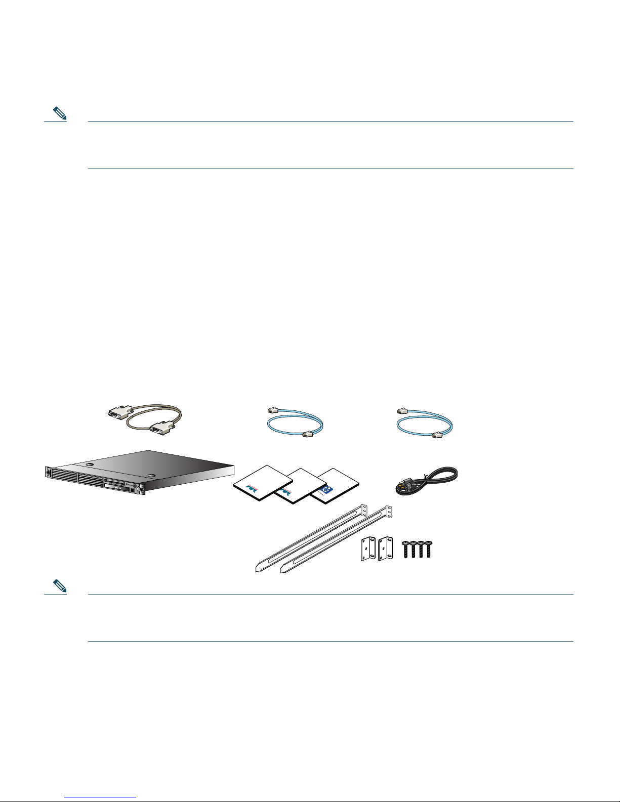
Verifying the Package Contents
Verify the contents of the packing box, shown in Figure 1, to ensure that you have received all items
necessary to install your Cisco NAC Appliance. Save the packing material in case you need to repack
the unit. If any item is missing or damaged, contact your Cisco representative or reseller for
instructions. Some Cisco NAC Appliance models might include additional items that are not shown.
Figure 1 Shipping Box Contents
Note Because product software is preloaded onto Cisco NAC-3300 Series appliances, the shipping
contents do not include a separate Cisco NAC Appliance software installation CD. Refer to
Upgrading Cisco NAC Appliance Software, page 5 for additional details.
Important
Safety
Information
Cisco NAC
Appliance
Getting Started
Guide
Cisco
Information
Packet
181022
Cisco NAC Appliance
RJ-45 cable
(straight-through)
AC power cord
Rack mounting kit
Documentation
DB-9 serial null modem cable
(for HA)
RJ-45 cable
(crossover; for HA)
Page 4

4
Failover Bundles
If you ordered a Failover Bundle, you will receive two physical Cisco NAC Appliances, and you will
need to perform the initial configuration on each machine as described in this guide. After initial
configuration is complete, configure High Availability (HA) using the CAM or CAS web console and
physically connect the appliances to create the HA pair. Refer to the “Configuring High Availability
(HA)” chapter of the latest Cisco NAC Appliance - Clean Access Manager Installation and
Configuration Guide, Release 4.5(1) for CAM HA configuration details and Cisco NAC Appliance Clean Access Server Installation and Configuration Guide, Release 4.5(1) for CAS HA configuration
details.
Note When connecting high availability (failover) pairs via serial cable, BIOS redirection to the
serial port must be disabled for NAC-3300 series appliances. Refer to the “Disable BIOS
Redirection for Serial HA (Failover) Connections” section of the Supported Hardware and
System Requirements for Cisco NAC Appliance (Cisco Clean Access) for details.
Equipment Required
You need to supply a workstation (PC or laptop) and keyboard/monitor/mouse to run the Cisco NAC
Appliance Configuration Utility on the appliance. Once the initial configuration is complete, you will
need a standard (straight-through) Ethernet Category 5 network cable with RJ-45 connectors to
connect the interfaces of the Cisco NAC Appliance to the network (eth0 for the CAM; eth0 and eth1
for the CAS). You will need a crossover RJ-45 Ethernet cable to connect HA-pair appliances together.
The Cisco NAC Appliance Hardware Summary, page 8 provides interface details for each model.
Rack Mounting
The Cisco NAC Appliance occupies one rack unit (1U). A rack-mounting kit is included in the
shipment. For rack-mounting information and instructions, refer to the 1U Rack Hardware
Installation Instructions document from HP included in the shipping box.
Cisco NAC Appliance Licensing
You need at least 1 Clean Access Manager license and 1 Clean Access Server license for your Cisco
NAC Appliance system to work. Both licenses are installed via the administration web console. For
Out-of-Band (OOB) deployments, you must add both the OOB CAS license and the CAS as an
Out-of-Band device to the CAM to access the OOB Management module of the CAM web console.
Page 5

5
• For instructions on how to obtain new license(s) for your system, see Cisco NAC Appliance Service
Contract/Licensing Support.
• For instructions on how to install licenses for your system (after initial configuration is complete),
see Install CAM License, page 45 and Add Additional Licenses, page 48.
Upgrading Cisco NAC Appliance Software
Cisco NAC-3300 Series appliances are preloaded with a default version of the Cisco NAC Appliance
software, which may not match the latest release of the software. Cisco recommends that you run the
latest supported version of the system software to ensure you have the latest product enhancements
and fixes.
Note Cisco NAC Appliance Release 4.5 (and later) only supports and can only be installed on
Cisco NAC Appliance CCA-3140, NAC-3310, NAC-3350, NAC-3390, and NME-NAC-K9
(NAC network module) platforms.
To upgrade Cisco NAC Appliance to the latest supported software version, you can either upgrade
your appliance via script or perform fresh CD installation of the latest Cisco NAC Appliance software
on your machines.
To upgrade any of the appliances, you can download and run the standard product upgrade file (e.g.
cca_upgrade-4.5.0-NO-WEB.tar.gz). The upgrade mechanism automatically determines whether the
machine is a Clean Access Server or a Lite/Standard/Super Clean Access Manager, and executes
accordingly. For step-by-step upgrade instructions, refer to the “Upgrading” section of the Release
Notes for Cisco NAC Appliance, Version 4.5(1) at
http://www.cisco.com/en/US/products/ps6128/prod_release_notes_list.html.
Starting from release 4.5, there is only one product installation CD (nac-4.5_0-K9.iso) for all appliance
platforms. The installation package determines whether the Clean Access Server, Clean Access
Manager, or Super Clean Access Manager was previously installed, as well as the previous software
version. See Installing Software via CD on Cisco NAC Appliance, page 28 for further details.
Downloading Cisco NAC Appliance Software
You can access the latest versions of upgrade and ISO files for Cisco NAC Appliance as follows.
Caution Before downloading or installing any Cisco NAC Appliance software, make sure to refer
to the Release Notes for that specific Cisco NAC Appliance release version at
http://www.cisco.com/en/US/products/ps6128/prod_release_notes_list.html to
understand the enhancements, caveats and upgrade impact to your existing deployment.
Page 6

6
Step 1 Log in with your Cisco ID and access the Software Download site for Cisco NAC Appliance:
a. You can go directly to the Software Download site at
http://www.cisco.com/cgi-bin/apps/tblbld/tablebuild.pl?topic=279515766.
b. Or, access the Cisco NAC Appliance support page at
http://www.cisco.com/en/US/partner/products/ps6128/index.html and click the “Download
Software” link.
Step 2 Click the link for the latest appropriate software release (e.g. “Cisco NAC Appliance Software
Version 4.5.x”).
Step 3 Refer to the “Release” column to locate the latest version of the product file (e.g. 4.5.x.y), and
click the filename link. Follow the prompts to download the file to your local computer.
Cisco NAC Appliance product files use the following file naming conventions:
• nac-4.5_x_y-K9.iso—Product ISO for CAS and Lite/Standard/Super CAM
• cca_upgrade-4.5.x.y-NO-WEB.tar.gz—Product Upgrade Archive
Note Files with the “CCAAgent” prefix are for the Cisco Clean Access Agent only.
Files with the “nme-nac” prefix are used for Cisco NAC Network Module only (see Getting
Started with Cisco NAC Network Modules in Cisco Access Routers for details).
Upgrading Firmware
Cisco NAC-3300 Series appliances are subject to any system BIOS/Firmware upgrades required for the
server model on which they are based.
For Cisco NAC-3310 platforms, refer to the “DL140 G3 Required BIOS/Firmware Upgrades” section
of the Supported Hardware and System Requirements for Cisco NAC Appliance (Cisco Clean Access)
for further details.
For More Information
For more information on Cisco NAC Appliance, refer to the following documents at
http://www.cisco.com/en/US/products/ps6128/tsd_products_support_series_home.html. When using
the online publications, refer to the documents that match the software version running on your
Cisco NAC Appliance (e.g. “Release 4.5”).
• Cisco NAC Appliance Data Sheet
• Cisco NAC Appliance Service Contract/Licensing Support
Page 7

7
• Supported Hardware and System Requirements for Cisco NAC Appliance
• Switch Support for Cisco NAC Appliance
• Support Information for Cisco NAC Appliance Agents, Release 4.5
• Release Notes for Cisco NAC Appliance, Version 4.5(1) (includes “Upgrading” section)
• Cisco NAC Appliance Configuration Quick Start Guide, Release 4.1 (software configuration)
• Cisco NAC Appliance - Clean Access Manager Installation and Configuration Guide, Release
4.5(1)
• Cisco NAC Appliance - Clean Access Server Installation and Configuration Guide, Release 4.5(1)
• Getting Started with Cisco NAC Network Modules in Cisco Access Routers
• Cisco NAC Profiler Installation and Configuration Guide, Release 2.1.8
For the latest online updates to this quick start guide, refer to
http://www.cisco.com/en/US/products/ps6128/prod_installation_guides_list.html.
For details on how to obtain technical support, refer to Obtaining Documentation and Submitting a
Service Request, page 53.
Page 8

8
2 Cisco NAC Appliance Hardware Summary
Table 1 summarizes the hardware specifications for each Cisco NAC Appliance. See the “Diagrams”
column for links to detailed diagrams showing NIC ports, power supply sockets, LEDs and buttons.
Table 1 Cisco NAC Appliance Hardware Summary
Cisco NAC
Appliance Product Hardware Specifications Diagrams
NAC-3310
1,2
MANAGER
Lite Manager
supporting up
to 3 standalone
or HA-pair
CASs
Single processor: Xeon 2.33 GHz dual core
1 GB RAM
80 GB NHP SATA HDD
4 10/100/1000 LAN ports [2 Broadcom
5721 integrated NICs; 2 Intel e1000 PCI-X
NICs (HP #NC360T)]
CD/DVD-ROM Drive
4 USB Ports (2 front, 2 rear)
Note NAC-3310 is based on HP ProLiant
DL140 G3.
• Cisco
NAC-3310
Front Panel,
page 10
• Cisco
NAC-3310
Front Panel
LEDs/Buttons,
page 11
• Cisco
NAC-3310 Rear
Panel, page 12
• Cisco
NAC-3310 Rear
Panel LEDs,
page 13
SERVER
CAS
supporting
100, 250, or
500 users
Page 9

9
NAC-3350
3
MANAGER
Standard
Manager
supporting up
to 20
standalone or
HA-pair CASs
Single processor: Xeon 3.0 GHz dual core
Dual power supply
2 GB RAM
2 x 72 GB SFF SAS RAID HDD
Smart Array E200i Controller
4 10/100/1000 LAN ports [2 Broadcom
5708 integrated NICs; 2 Intel e1000 PCI-X
NICs (HP #NC360T)]
CD/DVD-ROM Drive
4 USB Ports (1 front, 1 internal, 2 rear)
Cavium CN1120-NHB-E SSL Accelerator
Card
Note NAC-3350 is based on HP ProLiant
DL360 G5.
• Cisco
NAC-3350
Front Panel,
page 14
• Cisco
NAC-3350
Front Panel
LEDs/Buttons
• Cisco
NAC-3350 Rear
Panel, page 15
• Cisco
NAC-3350 Rear
Panel LEDs
SERVER
CAS
supporting
1500, 2500, or
3500 users
NAC-3390
3
MANAGER
Super Manager
supporting up
to 40
standalone or
HA-pair CASs
Dual processor: Xeon 3.0 GHz dual core
Dual power supply
4 GB RAM
4 x 72 GB SFF SAS RAID HDD
Smart Array E200i Controller
4 10/100/1000 LAN ports [2 Broadcom
5708 integrated NICs; 2 Intel e1000 PCI-X
NICs (HP #NC360T)]
CD/DVD-ROM Drive
4 USB Ports (1 front, 1 internal, 2 rear)
Cavium CN1120-NHB-E SSL Accelerator
Card
Note NAC-3390 is based on HP ProLiant
DL360 G5.
• Cisco
NAC-3390
Front Panel,
page 18
• Cisco
NAC-3390
Front Panel
LEDs /Buttons
• Cisco
NAC-3390 Rear
Panel, page 20
• Cisco
NAC-3390 Rear
Panel
LEDs/Buttons
1. NAC-3310 may require a firmware/BIOS upgrade for HP ProLiant DL140 G3. See Upgrading Firmware, page 6.
2. NAC-3310 supports iLO (Lights Out 100i Remote Management). The default iLO “Administrator” account has
default username/password: admin/admin. Defaults can be changed through the BIOS setup.
3. NAC-3350 and NAC-3390 support iLO2 (Integrated Lights Out, version 2). See panel tags for admin account details.
Table 1 Cisco NAC Appliance Hardware Summary (continued)
Cisco NAC
Appliance Product Hardware Specifications Diagrams
Page 10
10
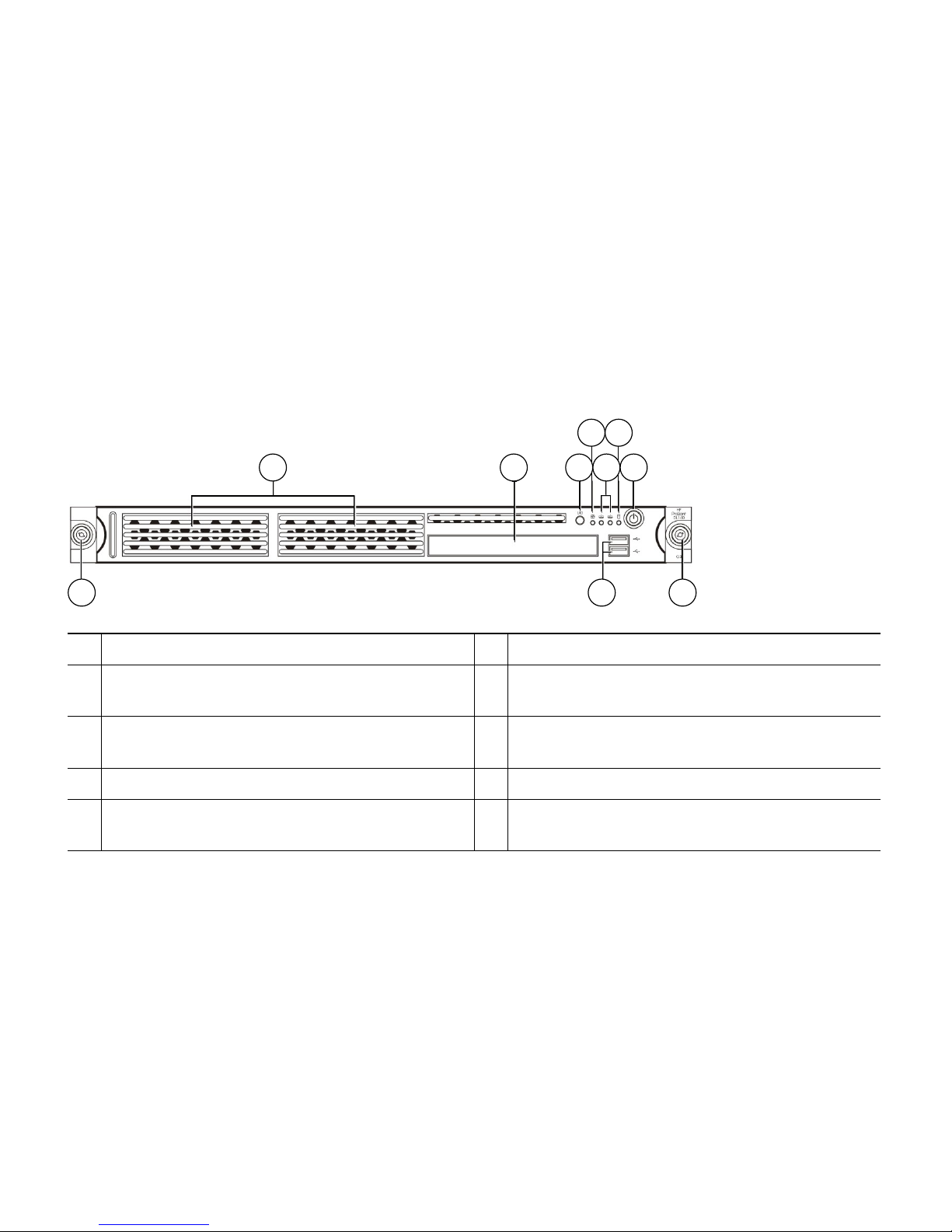
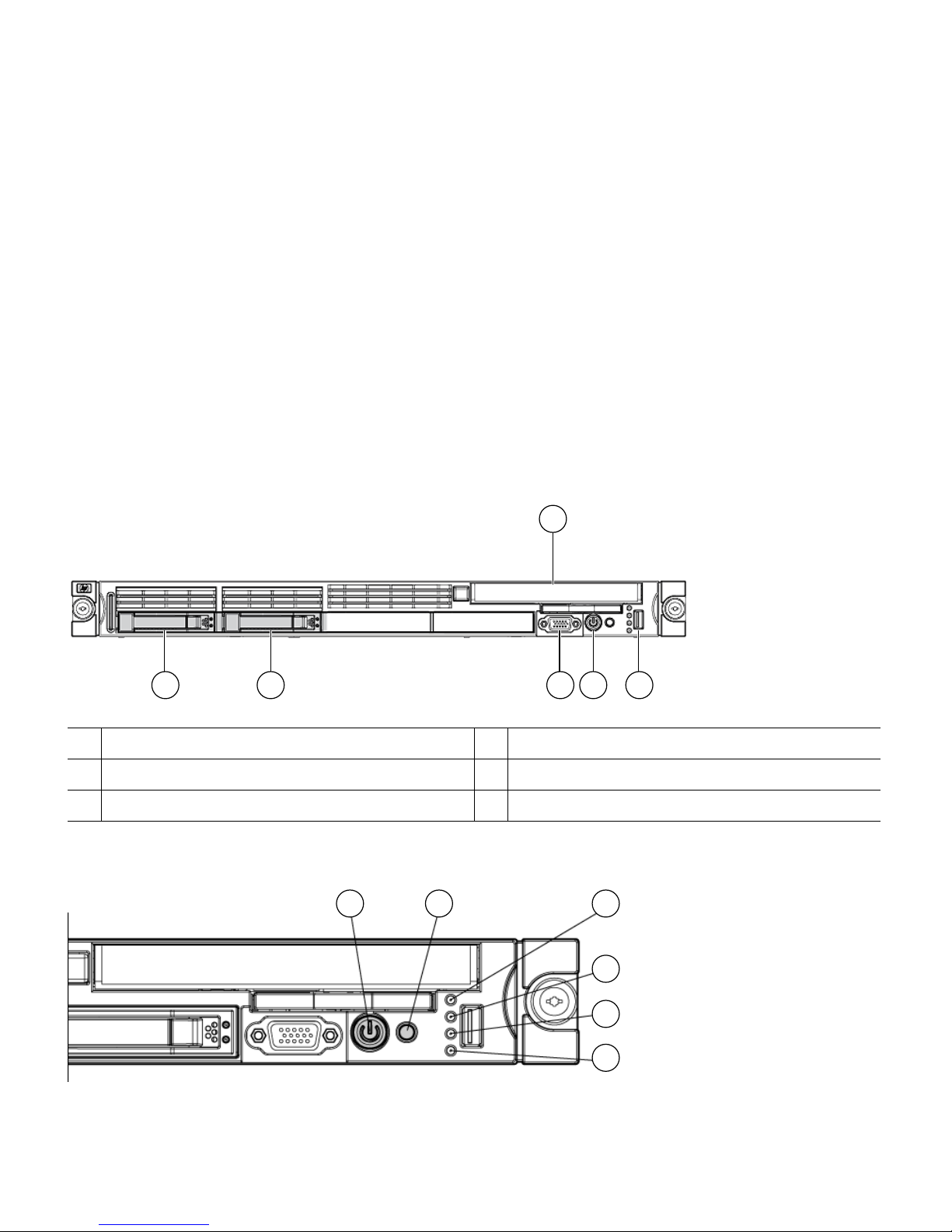
Cisco NAC-3310 Front and Rear Panels
The Cisco NAC-3310 Appliance is the recommended platform for Clean Access Lite Manager and
Clean Access Server (100/250/500 user count) deployments. A NAC-3310 CAM Lite can manage up
to 3 Clean Access Servers or 3 HA-CAS pairs. A NAC-3310 CAS can support 100, 250, or 500 users.
The Cisco NAC-3310 comes equipped with 4 network interfaces to provide flexibility in NIC interface
selection and to facilitate CAS high availability configuration.
For additional details, see Cisco NAC Appliance Hardware Summary, page 8.
Figure 2 Cisco NAC-3310 Front Panel
1
Hard disk drive (HDD) bay
6
HDD activity LED indicator (green)
2
CD-ROM/DVD drive
7
Power button with LED indicator (bicolor:
green/amber)
3
UID (Unit identification) button with
recessed LED indicator (blue)
8
Thumbscrews for the front bezel
4
System health LED indicator (amber)
9
Front USB ports
5
Activity/link status LED indicators for NIC 1
(eth0) and NIC2 (eth1) (green)
1 2 3
4 6
5 7
8 9 8
180955
Page 11

11
Figure 3 Cisco NAC-3310 Front Panel LEDs/Buttons
1
UID LED (recessed) Blue = A UID button has been pressed.
2
System health LED Off = System health is normal
Amber = A pre-failure system threshold has been breached. This
can be any of the following:
• At least one fan failure (system or processor fan)
• At least one of the temperature sensors reached critical level
(system or processor thermal sensors)
• At least one memory module failure
• A power supply unit error has occurred
3
Activity/link status LED
for NIC 1 (eth0) and NIC
2 (eth1)
Solid green = An active network link exists
Flashing green = An ongoing network data activity exists
Off = The server is off-line
4
HDD activity LEDs Flashing green = Ongoing drive activity
Off = No drive activity
5
Power status LED
(recessed)
Green = The server has AC power and is powered up
Amber = The server has AC power and is in standby mode
Off = The server is powered off (AC power disconnected)
UID
187416
1 2 3 4 5
Page 12
12
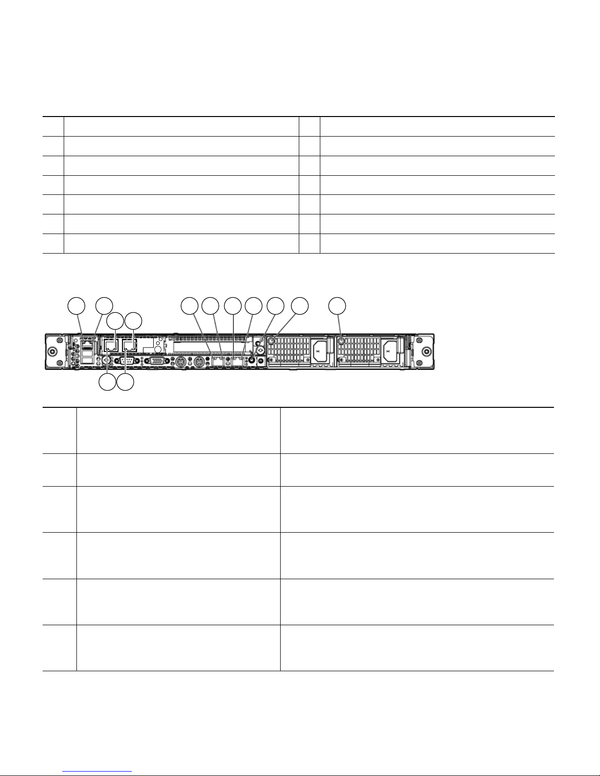
Figure 4 Cisco NAC-3310 Rear Panel
1
Ventilation holes
9
UID button with recessed LED indicator
(blue)
2
Thumbscrew for the top cover
10
Rear USB ports (black)
3
Thumbscrews for the PCI riser board
assembly
11
Video port (blue)
4
NIC 3 (eth2) and NIC 4 (eth3) PCI Express
GbE LAN (RJ-45) ports (Intel)
12
Serial port
513
PS/2 keyboard port (purple)
6
Standard height/full-length PCI Express
x16/PCI-X riser board slot cover
14
PS/2 mouse port (green)
7
Power supply cable socket
15
10/100 Mbps iLO LAN port for IPMI
management (RJ-45)
8
NIC 1 (eth0) and NIC 2 (eth1) integrated
GbE LAN (RJ-45) ports (Broadcom)
2 31 6 3 7
151312111098
14
180957
54
Page 13
13
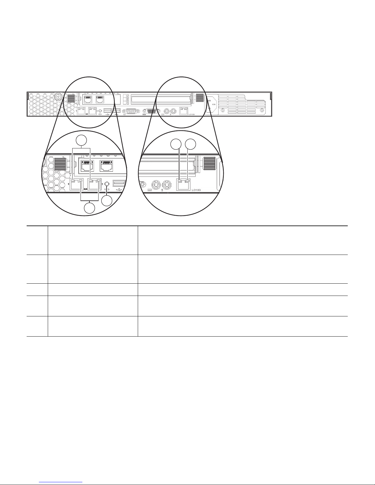
Figure 5 Cisco NAC-3310 Rear Panel LEDs
1
NIC activity/link status
LEDs for NIC 1 (eth0) and
NIC 2 (eth1)
Solid green = An active network link exists
Flashing green = An ongoing network data activity exists
Off = The server is off-line
2
NIC network speed LEDs Steady amber = The LAN connection is using a GbE link
Steady green = The LAN connection is using a 100 Mbps link
Off = The LAN connection is using a 10 Mbps link
3
UID LED (recessed) Blue = A UID button has been pressed
4
Link status LED for the
10/100 Mbps LAN port
Green = A network link exists
Off = No network link exists
5
Activity status LED for the
10/100 Mbps LAN port
Flashing green = Network activity exists
Off = No network activity exists
1
4 5
3
2
187417
Page 14
14
Cisco NAC-3350 Front and Rear Panels
The Cisco NAC-3350 Appliance provides enhanced capability for enterprise wide Clean Access
Standard Manager and Clean Access Server (1500/2500/3500 user count) deployments. A NAC-3350
Standard CAM can manage up to 20 Clean Access Servers or 20 HA-CAS pairs. A NAC-3350 CAS
can support up to 1500, 2500, or 3500 users.
Similar to the Cisco NAC-3310, the Cisco NAC-3350 comes equipped with 4 network interfaces to
provide flexibility in NIC interface selection and facilitate CAS high availability configuration. The
Cisco NAC-3350 additionally provides 2 GB of RAM, two SAS drives configured in RAID 0 and 1,
an SSL accelerator, and dual power supply to support large network deployments and provide added
reliability for a centralized CAM/CAS deployment in the network core.
For additional details, see Cisco NAC Appliance Hardware Summary, page 8.
Figure 6 Cisco NAC-3350 Front Panel
Figure 7 Cisco NAC-3350 Front Panel LEDs/Buttons
1
Hard drive bay 1
4
Video connector
2
Hard drive bay 2
5
HP Systems Insight Display
3
CD-ROM/DVD drive
6
USB connector
181236
3
1 2 4 5 6
1 2 3
4
5
6
180960
Page 15

15
Figure 8 Cisco NAC-3350 Rear Panel
1
Power On/Standby button
and system power LED
Green = System is on
Amber = System is shut down, but power is still applied
Off = Power cord is not attached, power supply failure has
occurred, no power supplies are installed; facility power is not
available, or disconnected power button cable
2
UID button/LED Blue = Identification is activated
Flashing blue = System is being managed remotely
Off = Identification is deactivated
3
Internal health LED Green = System health is normal
Amber = System health is degraded. (To identify the component in
a degraded state, refer to “HP Systems Insight Display and
LEDs.”)
Red = System health is critical. (To identify the component in a
critical state, refer to “HP Systems Insight Display and LEDs.”)
Off = System health is normal when in standby mode
4
External health LED
(power supply)
Green = Power supply health is normal
Amber = Power redundancy failure occurred
Off = Power supply health is normal when in standby mode
5
NIC 1 (eth0) link/activity
LED
Green = Network link exists
Flashing green = Network link and activity exist
Off = No link to network exists
If power is off, the front panel LED is not active. For status, view
the rear panel LED for the RJ-45 connector (Figure 9 on page 16).
6
NIC 2 (eth1) link/activity
LED
Green = Network link exists
Flashing green = Network link and activity exist
Off = No link to network exists
If power is off, the front panel LED is not active. For status, view
the rear panel LED for the RJ-45 connector (Figure 9 on page 16).
181237
2 3 4 5
67891011121314
1
Page 16
16
Figure 9 Cisco NAC-3350 Rear Panel LEDs
1
NIC 3 (eth2) PCI-X port (Intel)
8
Keyboard connector (purple)
2
NIC 4 (eth3) PCI-X port (Intel)
9
Mouse connector (green)
3
PCI Express expansion slot 2
10
Video connector (blue)
4
Power supply bay 1
11
Serial connector
5
Power supply bay 2
12
USB connector
6
Integrated NIC 2 (eth1) port (Broadcom)
13
USB connector
7
Integrated NIC 1 (eth0) port (Broadcom)
14
iLO 2 NIC connector (RJ-45)
1
iLO 2 NIC activity LED Green = Activity exists
Flashing green = Activity exists
Off = No activity exists
2
iLO 2 NIC link LED Green = Link exists
Off = No link exists
3
10/100/1000 NIC 3 (Intel) Activity
LED
Steady green = High activity
Flashing green = Activity exists
Off = No activity (if link LED is off, link is dead)
4
10/100/1000 NIC 3 (Intel) Link LED Orange = 1000 Mbps
Green = 100 Mbps
Off = 10 Mbps (if activity LED is off, link is dead)
5
10/100/1000 NIC 4 (Intel) Activity
LED
Steady green = High activity
Flashing green = Activity exists
Off = No activity (if link LED is off, link is dead)
6
10/100/1000 NIC 4 (Intel) Link LED Orange = 1000 Mbps
Green = 100 Mbps
Off = 10 Mbps (if activity LED is off, link is dead)
181238
1 2 7 8 9 10 11 12 13
3 5
4 6
Page 17

17
7
10/100/1000 NIC 1 (Broadcom)
Activity LED
Green = Activity exists
Flashing green = Activity exists
Off = No activity exists
8
10/100/1000 NIC 1 (Broadcom) Link
LED
Green = Link exists
Off = No link exists
9
10/100/1000 NIC 2 (Broadcom)
Activity LED
Green = Activity exists
Flashing green = Activity exists
Off = No activity exists
10
10/100/1000 NIC 2 (Broadcom) Link
LED
Green = Link exists
Off = No link exists
11
UID button/LED Blue = Identification is activated
Flashing blue = System is being managed remotely
Off = Identification is deactivated
12
Power supply 1 LED Green = Normal
Off = System is off or power supply has failed
13
Power supply 2 LED Green = Normal
Off = System is off or power supply has failed
Page 18

18
Cisco NAC-3390 Front and Rear Panels
The Cisco NAC-3390 Appliance platform provides the enhanced processing, memory, and power
necessary for enterprise wide deployment of the Clean Access Super Manager (Super CAM) which can
support up to 40 Clean Access Servers or 40 HA-CAS pairs. The Cisco NAC-3390 features dual
processors, dual power supplies, 4 GB of RAM, 4 hard disk drives, two integrated NICs, and an SSL
accelerator. For additional details, see Cisco NAC Appliance Hardware Summary, page 8.
Note The Super CAM software is supported only on the Cisco NAC-3390 Appliance platform.
Figure 10 Cisco NAC-3390 Front Panel
Figure 11 Cisco NAC-3390 Front Panel LEDs /Buttons
1
Hard drive bay 1
5
CD-ROM/DVD drive
2
Hard drive bay 2
6
Video connector
3
Hard drive bay 3
7
HP Systems Insight Display
4
Hard drive bay 4
8
USB connector
180958
5
1 2 3 4 6 7 8
1 2 3
4
5
6
180960
Page 19

19
1
Power On/Standby button
and system power LED
Green = System is on
Amber = System is shut down, but power is still applied
Off = Power cord is not attached, power supply failure has
occurred, no power supplies are installed; facility power is not
available, or disconnected power button cable
2
UID button/LED Blue = Identification is activated
Flashing blue = System is being managed remotely
Off = Identification is deactivated
3
Internal health LED Green = System health is normal
Amber = System health is degraded. (To identify the component
in a degraded state, refer to “HP Systems Insight Display and
LEDs.”)
Red = System health is critical. (To identify the component in a
critical state, refer to “HP Systems Insight Display and LEDs.”)
Off = System health is normal when in standby mode
4
External health LED
(power supply)
Green = Power supply health is normal
Amber = Power redundancy failure occurred
Off = Power supply health is normal when in standby mode
5
NIC 1 link/activity LED Green = Network link exists
Flashing green = Network link and activity exist
Off = No link to network exists
If power is off, the front panel LED is not active. For status, view
the rear panel LED for the RJ-45 connector (Figure 13 on
page 20)
6
NIC 2 link/activity LED Green = Network link exists
Flashing green = Network link and activity exist
Off = No link to network exists
If power is off, the front panel LED is not active. For status, view
the rear panel LED for the RJ-45 connector (Figure 13 on
page 20)
Page 20

20
Figure 12 Cisco NAC-3390 Rear Panel
Figure 13 Cisco NAC-3390 Rear Panel LEDs/Buttons
1
PCI Express expansion slot 1, low-profile,
half-length
8
Mouse connector (green)
2
Cavium SSL Accelerator Card (PCI Express
expansion slot 2)
9
Video connector (blue)
3
Power supply bay 1
10
Serial connector
4
Power supply bay 2
11
USB connector
5
Integrated NIC 2 (eth1) port (Broadcom)
12
USB connector
6
Integrated NIC 1 (eth0) port (Broadcom)
13
iLO 2 NIC connector (RJ-45)
7
Keyboard connector (purple)
1
iLO 2 NIC activity LED Green = Activity exists
Flashing green = Activity exists
Off = No activity exists
2
iLO 2 NIC link LED Green = Link exists
Off = No link exists
3
10/100/1000 NIC 1 Activity LED Green = Activity exists
Flashing green = Activity exists
Off = No activity exists
180961
1 2 3 4
5678910111213
180962
1 2 3 4 5 6 7 8 9
Page 21

21
4
10/100/1000 NIC 1 Link LED Green = Link exists
Off = No link exists
5
10/100/1000 NIC 2 Activity LED Green = Activity exists
Flashing green = Activity exists
Off = No activity exists
6
10/100/1000 NIC 2 Link LED Green = Link exists
Off = No link exists
7
UID button/LED Blue = Identification is activated
Flashing blue = System is being managed remotely
Off = Identification is deactivated
8
Power supply 1 LED Green = Normal
Off = System is off or power supply has failed
9
Power supply 2 LED Green = Normal
Off = System is off or power supply has failed
Page 22

22
3 Configuration Worksheets
You will need the following information to complete the initial configuration of your NAC Appliances:
• Clean Access Manager (CAM) Configuration Worksheet
• Clean Access Server (CAS) Configuration Worksheet
• CAS Mode IP Addressing Considerations
Note If planning to configure your appliances for high availability (HA), you first must perform
initial installation on each appliance, then configure HA via the CAM and/or CAS web
console(s). You will need to create a virtual Service IP for the HA-pair via web configuration.
Clean Access Manager (CAM) Configuration Worksheet
Table 2 CAM Configuration Utility Worksheet
For Clean Access Manager NAC Appliance
a. IP address for eth0 interface (trusted) 1:
b. Subnet mask (IP netmask) for eth0 interface:
c. Default gateway IP address for eth0 interface:
d. Host name for your CAM:
e. IP address of Domain Name Server on your network:
f. Shared secret:
Must be the same for the CAM and all CASs
g. Date, time and timezone:
h. To generate the required temporary SSL certificate
(you can change this at a later time):
FQDN or IP address of CAM:
Organization unit (e.g. Sales)
Organization name (e.g. Cisco)
Organization location (e.g. San Jose, CA, US)
Note If using FQDN, make sure your DNS server
is set up for the domain name.
i. Root user password:
2
Page 23

23
Clean Access Server (CAS) Configuration Worksheet
1. eth0 and eth1 generally correlate to the first two network cards—NIC 1 and NIC 2—on most types of server
hardware.
2. Cisco highly recommends replacing default password(s) with “strong” passwords (at least 8 characters long,
comprised of a combination of two characters from each of the upper- and lower-case letters, numbers, and special
characters categories)
Table 3 CAS Configuration Utility Worksheet
For Clean Access Server NAC Appliance
a. IP address for eth0 interface (trusted) 1:
1. eth0 and eth1 generally correlate to the first two network cards—NIC 1 and NIC 2—on most types of server
hardware.
b. Subnet mask (IP netmask) for eth0 interface:
c. Default gateway IP address for eth0 interface:
d. IP address for eth1 interface (untrusted):
e. Subnet mask (IP netmask) for eth1 interface:
f. Default gateway IP address for eth1 interface
1
:
g. Host name for your CAS:
h. IP address of Domain Name Server on your network:
i. Shared secret:
Must be the same for the CAM and all CASs
j. Date, time and timezone:
k. To generate the required temporary SSL certificate
(you can change this at a later time):
FQDN or eth0 IP address of CAS:
Organization unit (e.g. Sales)
Organization name (e.g. Cisco)
Organization location (e.g. San Jose, CA, US)
Note If using FQDN, make sure your DNS server
is set up for the domain name.
l. Root user password
2
:
m. Web console password
2
:
Page 24

24
CAS Mode IP Addressing Considerations
2. Cisco highly recommends replacing default password(s) with “strong” passwords (at least 8 characters long,
comprised of a combination of two characters from each of the upper- and lower-case letters, numbers, and special
characters categories)
Table 4 CAS Modes— IP addressing Considerations
CAS Mode Comments
Real-IP • The trusted (eth0) and untrusted (eth1) interfaces of the CAS must be on
different subnets.
• Add static routes on the L3 switch or router to route traffic for the managed
subnets to the trusted interface of the respective CASs.
• If using DHCP relay, make sure the DHCP server has a route back to the
managed subnets.
NAT (testing
only)
Note: NAT is not supported for production deployments
• The trusted (eth0) and untrusted (eth1) interfaces of the CAS must be on
different subnets.
Page 25

25
Virtual Gateway CAUTION: To avoid switch errors, do not connect the untrusted interface (eth1)
of a Virtual Gateway (IB or OOB) CAS to the switch until after the CAS is added
to the CAM via the web console, and VLAN mapping is configured correctly
under Device Management > CCA Servers > Manage [CAS_IP] > Advanced >
VLAN Mapping. See the Cisco NAC Appliance - Clean Access Server Installation
and Configuration Guide, Release 4.5(1) for details.
• The CAS and CAM must be on different subnets (or VLANs).
• The trusted (eth0) and untrusted interfaces (eth1) of the CAS can have the
same IP address. (Note: this is equivalent to an L3 SVI IP address.)
• All end devices in the bridged subnet must be on the CAS untrusted side.
• The CAS is automatically configured for DHCP Passthrough when set to
Virtual Gateway mode.
• Managed subnets must be configured on the CAS for all the user subnets that
are managed by the CAS. When configuring the Managed subnet, make sure
that you type an unused IP address in that subnet (for the CAS to use), and
not a subnet address.
• Traffic from clients must pass through the CAS before hitting the gateway.
• When the CAS is an OOB VGW, the following also applies:
CAS interfaces must be on a separate subnet (or VLAN) from the CAM.
The CAS management VLAN must be on a different VLAN than the user or
Access VLANs.
See also “Determining VLANs For Virtual Gateway” in the Cisco NAC Appliance
- Clean Access Server Installation and Configuration Guide, Release 4.5(1) for
further details.
Table 4 CAS Modes— IP addressing Considerations (continued)
CAS Mode Comments
Page 26

26
4 Connecting the Cisco NAC Appliance
To perform initial configuration, you will need to connect to your CAM and CAS Cisco NAC
Appliances and access the command line. The following steps describe how to connect to either
appliance.
Step 1 Access the Cisco NAC Appliance command line for each machine in one of two ways:
a. Connect a monitor and keyboard directly to the machine via the keyboard/video monitor
connectors on the back panel of the machine (preferred method).
b. Connect a serial cable from a workstation (PC/laptop) to the machine and open a serial
connection on the workstation using terminal emulation software (such as HyperTerminal or
SecureCRT). For details, see Connecting Serially to the Cisco NAC Appliance, page 27.
Step 2 Connect a straight-through Category 5 Ethernet cable to the eth0 (NIC1) 10/100/1000
Ethernet port on the back panel of the Cisco NAC Appliance (CAM or CAS) and to your local
area network.
Step 3 Additionally, for the CAS appliance:
a. If planning to configure the CAS as a Virtual Gateway—either In-Band (IB) or Out-of-Band
(OOB)—do not connect the untrusted interface (eth1 (NIC2)) of the CAS until after you have
added the CAS to the CAM from the web administrator console (and, for Central
Deployments, configured VLAN Mapping) to prevent network connectivity issues. For
details, see the Cisco NAC Appliance - Clean Access Server Installation and Configuration
Guide, Release 4.5(1).
b. If planning to configure the CAS as a Real-IP Gateway (or NAT Gateway for testing), connect
a straight-through Category 5 Ethernet cable to the eth1 (NIC2) 10/100/1000 Ethernet port
on the back panel of the CAS and to your local area network.
Step 4 Connect the AC power cord to the back panel of the Cisco NAC Appliance and to a grounded
AC outlet.
Step 5 Power on the Cisco NAC Appliance by pressing the power button on the front of the
appliance. The diagnostic LEDs will flash a few times as part of the power-on self-test (POST).
Status messages are displayed on the console as the appliance boots up.
Continue to Installing Software via CD on Cisco NAC Appliance, page 28 or Running the Configuration
Utility, page 32.
Page 27

27
Connecting Serially to the Cisco NAC Appliance
This section describes how to connect serially to the Cisco NAC Appliance to access the command line.
Step 1 To use a serial connection, use a serial cable (DB-9, female-female) to connect your PC/laptop
to the serial port on the Cisco NAC Appliance. (You can use the null modem cable shipped in
the box if needed.)
After physically connecting your workstation to the appliance, you can access the serial
connection interface using a variety of terminal emulation applications. The following steps
may vary depending on the software being used.
Step 2 If using Microsoft® HyperTerminal, click Start > All Programs > Accessories >
Communications > HyperTerminal to open the HyperTerminal window.
Step 3 Type a name for the session and click OK.
Step 4 In the Connect using list, choose the COM port on the workstation to which the serial cable
is connected (e.g. COM3 or COM1) and click OK.
Step 5 Configure the Port Settings as follows: Bits per second – 9600, Data bits – 8, Parity – None,
Stop bits – 1, Flow control – Hardware (CTS/RTS) (or None).
Step 6 Click the Disconnect icon, then go to File > Properties to open the Properties dialog for the
session. Click the Settings tab, and set the Emulation dropdown to VT100. Click OK, then
click the Call icon.
You should be able to access the command line interface of the appliance (it may take a
minute).
Note If a Cisco NAC Appliance is configured for high availability (HA), and serial heartbeat is
being used for HA, then the serial port can no longer be used for serial console.
Continue to Installing Software via CD on Cisco NAC Appliance, page 28 or Running the Configuration
Utility, page 32.
Page 28

28
5 Installing Software via CD on Cisco NAC Appliance
Note If you prefer to perform initial configuration using the default version of the system software
shipped with the appliance, skip this section and proceed to Running the Configuration
Utility, page 32. You can always upgrade your appliance later, as mentioned in Upgrading
Cisco NAC Appliance Software, page 5.
Cisco NAC-3310, NAC-3350, and NAC-3390 appliances are preloaded with a default version of the
Cisco NAC Appliance system software. The first time a Cisco NAC-3300 appliance is powered on, it
prompts for root user login and starts the initial configuration script as described in Running the
Configuration Utility, page 32. Cisco recommends upgrading to the latest software release supported
for the Cisco NAC-3300 series.
Note that starting from Release 4.5:
• There is only one product installation CD (ISO) for all appliance platforms (CAS and
Lite/Standard/Super CAM).
• The DL140 and serial_DL140 boot installation directives are no longer required when installing
the software on NAC-3310 appliances.
Use the following instructions to perform CD installation of the latest supported software version
directly onto your appliance:
• For a MANAGER appliance, refer to Install the Clean Access Manager (CAM) Software from
CD-ROM, page 29.
• For a SERVER appliance, refer to Install the Clean Access Server (CAS) Software from CD-ROM,
page 30.
Note CD software installation on a configured appliance will remove all previous configuration.
Cisco recommends upgrading configured appliances to the latest software release using the
upgrade procedure. The upgrade package determines whether the Clean Access Server, Clean
Access Manager, or Super Clean Access Manager was previously installed, as well as the
previous software version.
Page 29

29
Install the Clean Access Manager (CAM) Software from CD-ROM
The following steps describe how to perform optional CD installation of the Clean Access Manager
software on the NAC-3310 MANAGER, NAC-3350 MANAGER, and NAC-3390 MANAGER
appliances.
Step 1 Connect the target installation machine to the network and access the command line of the
machine by direct console or over a serial connection, as described in Connecting the Cisco
NAC Appliance, page 26.
Step 2 Download the latest software version supported on the target machine as follows:
a. Log In to Cisco Secure Software, and download the latest supported nac-<version>-K9.iso
file from http://www.cisco.com/cgi-bin/apps/tblbld/tablebuild.pl?topic=279515766. See
Downloading Cisco NAC Appliance Software, page 5 for more details.
b. Burn the ISO as a bootable disk to a CD-R. Insert the CD into the CD-ROM drive of each
installation machine.
Note Cisco recommends burning the ISO image to a CD-R using speeds 10x or lower. Higher
speeds can result in corrupted/unbootable installation CDs.
Step 3 Insert the CD-ROM containing the Cisco NAC Appliance ISO file into the CD-ROM drive of
the target machine.
Step 4 Reboot the machine. The Cisco Clean Access Installer welcome screen appears after the
machine restarts:
Cisco Clean Access 4.5-0 Installer (C) 2008 Cisco Systems, Inc.
Welcome to the Cisco Clean Access 4.5-0 Installer!
- To install a Cisco Clean Access device, press the <ENTER> key.
- To install a Cisco Clean Access device over a serial console, enter serial at
the boot prompt and press the <ENTER> key.
boot:
Step 5 At the “boot:” prompt, type one of the following options depending on the type of
connection:
• Press the Enter key if your monitor and keyboard are directly connected to the appliance.
• Type
serial and press enter in the terminal emulation console if you are accessing the
appliance over a serial connection.
Page 30

30
Step 6 The Install selection option appears next, prompting you to perform a brand new installation
of Cisco NAC Appliance or exit/cancel the install process. At the following prompt, enter
1
to install a new version of Cisco NAC Appliance.
Checking for existing installations.
Clean Access Manager 4.1.3.1 installation detected.
Please choose one of the following actions:
1) Install.
2) Exit.
Step 7 Next, the Cisco NAC Appliance software installer asks you to specify whether you are
installing a Clean Access Manager or Clean Access Server. At the following prompt, enter
1
to perform the installation for a Clean Access Manager.
Please choose one of the following configurations:
1) CCA Manager.
2) CCA Server.
Caution Only one CD is used for installation of the Clean Access Manager or Clean Access Server
software. You must select the appropriate type, either CAM or CAS, for the target
machine on which you are performing installation.
Step 8 The Clean Access Manager Package Installation then executes. The installation takes several
minutes. When finished, the installation script presents the following message, prompting you
to press Enter to reboot the CAM and launch the Clean Access Manager quick configuration
utility.
Installation complete. Press <ENTER> to continue
After you press Enter, the welcome screen for the Clean Access Manager quick configuration utility
appears, and a series of questions prompt you for the initial configuration, as described in Run CAM
Configuration Utility Script, page 33.
Install the Clean Access Server (CAS) Software from CD-ROM
The following steps describe how to perform optional CD installation of the Clean Access Server
software on NAC-3310 SERVER or NAC-3350 SERVER appliances.
Step 1 Connect the target installation machine to the network and access the command line of the
machine by direct console or over a serial connection, as described in Connecting the Cisco
NAC Appliance, page 26.
Page 31

31
Step 2 Download the latest software version supported on the target machine as follows:
a. Log In to Cisco Secure Software, and download the latest supported nac-<version>-K9.iso
file from http://www.cisco.com/cgi-bin/apps/tblbld/tablebuild.pl?topic=279515766. See
Downloading Cisco NAC Appliance Software, page 5 for more details.
b. Burn the ISO as a bootable disk to a CD-R. Insert the CD into the CD-ROM drive of each
installation machine.
Note Cisco recommends burning the ISO image to a CD-R using speeds 10x or lower. Higher
speeds can result in corrupted/unbootable installation CDs.
Step 3 Insert the CD-ROM containing the Clean Access Server ISO file into the CD-ROM drive of the
target CAS machine.
Step 4 Reboot the machine. The Cisco Clean Access Installer welcome screen appears after the
machine restarts:
Cisco Clean Access 4.5-0 Installer (C) 2008 Cisco Systems, Inc.
Welcome to the Cisco Clean Access 4.5-0 Installer!
- To install a Cisco Clean Access device, press the <ENTER> key.
- To install a Cisco Clean Access device over a serial console, enter serial at
the boot prompt and press the <ENTER> key.
boot:
Step 5 At the “boot:” prompt, type one of the following options depending on the type of
connection:
• Press the Enter key if your monitor and keyboard are directly connected to the CAS.
• Type
serial and press enter in the terminal emulation console if you are accessing the
appliance over a serial connection.
Step 6 The Install selection option appears next prompting you to perform a brand new installation
of Cisco NAC Appliance or exit/cancel the install process. At the following prompt, enter
1
to install a new version of Cisco NAC Appliance.
Checking for existing installations.
Clean Access Server 4.1.3.1 installation detected.
Please choose one of the following actions:
1) Install.
2) Exit.
Step 7 Next, the Cisco NAC Appliance software installer asks you to specify whether you are
installing a Clean Access Manager or Clean Access Server. At the following prompt, enter
2
to perform the installation for a Clean Access Server.
Page 32

32
Please choose one of the following configurations:
1) CCA Manager.
2) CCA Server.
Caution Only one CD is used for installation of the Clean Access Manager or Clean Access Server
software. You must select the appropriate type, either CAM or CAS, for the target
machine on which you are performing installation.
Step 8 The Clean Access Server Package Installation then executes. The installation takes several
minutes. When finished, the installation script presents the following message, prompting you
to press Enter to reboot the CAS and launch the Clean Access Server quick configuration
utility.
Installation complete. Press <ENTER> to continue
When finished, the welcome screen for the Clean Access Server quick configuration utility appears, and
a series of questions prompt you for the initial CAS configuration, as described in
Run CAS
Configuration Utility Script, page 37.
6 Running the Configuration Utility
Once you have booted up the appliance, or if you have installed a new release on your Cisco NAC
Appliance, you are prompted to perform the initial configuration as described in this section.
• To configure the MANAGER, follow the steps in Run CAM Configuration Utility Script, page 33.
• To configure the SERVER, follow the steps in Run CAS Configuration Utility Script, page 37.
After completing initial configuration on both the MANAGER (CAM) and SERVER (CAS), continue
Accessing the CAM Web Console, page 45.
Note If you have previously installed and configured your CAM and are using this section to alter
your current configuration, you can also launch the CAM configuration utility by logging in
to the CAM or CAS direct console and entering
service perfigo config. For more
information, see Manually Restarting the Configuration Utility, page 44.
Page 33

33
Run CAM Configuration Utility Script
Step 1 After the software is installed from the CD and package installation is complete, the welcome
script for the configuration utility appears
:
Welcome to the Cisco Clean Access Manager quick configuration utility.
Note that you need to be root to execute this utility.
The utility will now ask you a series of configuration questions.
Please answer them carefully.
Cisco Clean Access Manager, (C) 2008 Cisco Systems, Inc.
Note If this prompt does not appear after you install the Cisco NAC Appliance software and restart
the CAM, refer to Manually Restarting the Configuration Utility, page 44.
Step 2 When prompted, type an IP address for the eth0 (trusted) interface of the CAM (from field a.
of the CAM Worksheet) and press Enter. Confirm the value when prompted, or type
n and
press Enter to correct the entry.
Configuring the network interface:
Please enter the IP address for the interface eth0 []: 10.201.240.11
You entered 10.201.240.11 Is this correct? (y/n)? [y]
Step 3 Type the subnet mask for the interface address (from field b.) at the prompt or press Enter for
the default (255.255.255.0). Confirm the value when prompted.
Please enter the netmask for the interface eth0 []: 255.255.255.0
You entered 255.255.255.0, is this correct? (y/n)? [y]
Step 4 Accept the default gateway or specify and confirm a default gateway address (from field c.)
for the Clean Access Manager. This is typically the IP address of the router between the CAM
subnet and the CAS subnet.
Please enter the IP address for the default gateway []: 10.201.240.1
You entered 10.201.240.1. Is this correct? (y/n)? [y]
Step 5 Type a host name for the Clean Access Manager (from field d.) To use the CAM host name
for the CAM web console, make sure to create an entry in your DNS server.
The default host
name is
nacmanager.
Please enter the hostname [nacmanager]: cam3350
You entered cam3350 Is this correct? (y/n)? [y]
Step 6 Type the IP address of the Domain Name System (DNS) server in your environment (from field
e.) or accept the default at the following prompt:
Please enter the IP addresses for the name servers: []: 63.93.96.94
You entered 63.93.96.94 Is this correct? (y/n)? [y]
Page 34

34
Step 7 The Clean Access Manager and Clean Access Servers in a deployment authenticate each other
through a shared secret that serves as an internal password. The default shared secret is
cisco123. Type and confirm the shared secret (from field f.) at the prompts.
The shared secret used between Clean Access Manager and Clean Access Server is the
default string: cisco123
This is highly insecure. It is recommended that you choose a string that is unique
to your installation.
Please remember to configure all Clean Access Devices with the same string.
Only the first 8 characters supplied will be used.
Please enter the shared secret between Clean Access Server and Clean Access
Manager: cisco123
You entered: cisco123
Is this correct? (y/n)? [y]
Caution The shared secret must be the same for the Clean Access Manager and all Clean Access
Servers in the deployment. If they have different shared secrets, they cannot communicate.
Step 8 Specify the time zone in which the Clean Access Manager is located (from field g.) as follows:
The timezone is currently not set on this system.
Please identify a location so that time zone rules can be set correctly.
Please select a continent or ocean.
a. Choose your region from the continents and oceans list. Type the number next to your
location on the list, such as
2 for the Americas, and press Enter. Type 11 to enter the time zone
in Posix TZ format, such as
GST-10.
b. The next list that appears shows the countries for the region you chose. Choose your country
from the country list, such as
45 for the United States, and press Enter.
c. If the country contains more than one time zone, the time zones for the country appears.
d. Choose the appropriate time zone region from the list, such as
19 for Pacific Time, and press
Enter.
e. Confirm your choices by entering
1, or use 2 to cancel and start over.
The following information has been given:
United States
Pacific Time
Is the above information OK?
1) Yes
2) No
#? 1
Step 9 Type and confirm the current date and time, using format hh:mm:ss mm/dd/yy.
Current date and time hh:mm:ss mm/dd/yy [11:53:12 08/22/08]: 11:53:12 08/22/08
You entered 11:53:12 08/22/08 Is this correct? (y/n)? [y] y
Page 35

35
Step 10 Follow the prompts to configure the temporary SSL security certificate that enables secure
connections between the CAM and the administrator web console (using field h.):
a. Type the IP address or domain name for which you want the certificate to be issued, or press
enter to accept the default IP address (typically the eth0 IP address you already specified, for
example
10.201.240.11).
Note This is also the IP address or domain name to which the web server responds. If DNS
is not already set up for a domain name, the CAM web console will not load. Make
sure to create a DNS entry in your servers, or else use an IP address for the CAM.
b. For the organization unit name, enter the group within your organization that is responsible
for the certificate (for example,
DOC).
c. For the organization name, type the name of your organization or company for which you
would like to receive the certificate (for example,
Cisco Systems), and press Enter.
d. Type the name of the city or county in which your organization is legally located (for example,
San Jose), and press Enter.
e. Type the two-character state code in which the organization is located (for example,
CA or NY),
and press Enter.
f. Type the two-letter country code (for example,
US), and press Enter.
Step 11 Confirm values and press Enter to generate the SSL certificate or type
n to restart.
You entered the following:
Domain: 10.201.240.11
Organization unit: DOC
Organization name: Cisco Systems
City name: San Jose
State code: CA
Country code: US
Is this correct? (y/n)? [y] y
Note You must generate the temporary SSL certificate or you will not be able to access the CAM
web console.
Step 12 Specify whether or not you want the CAM to feature Pre-login Banner Support at the
following prompt.
Enable Prelogin Banner Support? (y/n)? [n]
For more information and an example of the Pre-login Banner feature, see the “Installing the
Clean Access Manager” chapter of the Cisco NAC Appliance - Clean Access Manager
Installation and Configuration Guide, Release 4.5(1).
Page 36

36
Step 13 Configure the root user password for the installed Linux operating system of the Clean Access
Manager. The
root user account is used to access the system over a serial connection or
through SSH.
Cisco NAC Appliance supports using Strong Passwords for root user login. Passwords must
be at least 8 characters long and feature a combination of upper- and lower-case letters, digits,
and other characters. For example, the password
10-9=One does not satisfy the requirements
because it does not contain two characters from each category, but
1o-9=OnE is a valid
password. For more details, see the “Administering the CAM” chapter of the Cisco NAC
Appliance - Clean Access Manager Installation and Configuration Guide, Release 4.5(1).
For security reasons, it is highly recommended that you change the password for
the root user.
** Please enter a valid password for root user as per the requirements below! **
Changing password for user root.
You can now choose the new password.
A valid password should be a mix of upper and lower case letters,
digits, and other characters. Minimum of 8 characters and maximum
of 16 characters with characters from all of these classes. Minimum
of 2 characters from each of the four character classes is mandatory.
An upper case letter that begins the password and a digit that ends
it do not count towards the number of character classes used.
Enter new password:
Re-type new password:
passwd: all authentication tokens updated successfully.
Step 14 Next type the password for the admin user for the CAM direct access web console.
Please enter an appropriately secure password for the web console admin user.
New password for web console admin:
Confirm new password for web console admin:
Step 15 After the configuration is complete, press Enter to reboot the CAM. After rebooting, the CAM
will be accessible from the web console.
Configuration is complete.
Changes require a REBOOT of Clean Access Manager.
Enter the following command to reboot the CAM after configuration is complete:
# reboot
The CAM initial configuration is now complete.
Step 16 Test the installation:
a. Ping the eth0 interface address from a command line. If working properly, the interface should
respond to the ping.
Page 37

37
b. If the CAM does not respond, try connecting to the CAM using SSH (Secure Shell). Connect
with the
root username and password. Once connected, try pinging the default gateway to
see if the CAM can reach the external network.
If both tests fail, make sure that you have configured the IP address correctly and that the
other network settings are correct.
If after installation you need to reset the initial configuration settings for the CAM, connect
to the CAM machine directly or through SSH and use the CLI command
service perfigo
config.
Once the CAM is configured, you will be able to access the CAM web console to add product
licenses, and add initially configured Clean Access Servers to the CAM for management and
further configuration, as described in Accessing the CAM Web Console, page 45.
Step 17 Continue to Run CAS Configuration Utility Script, page 37 to initially configure your Clean
Access Servers.
Run CAS Configuration Utility Script
Step 1 After the software is installed from the CD and package installation is complete, the welcome
script for the configuration utility appears
:
Welcome to the Cisco Clean Access Manager quick configuration utility.
Note that you need to be root to execute this utility.
The utility will now ask you a series of configuration questions.
Please answer them carefully.
Cisco Clean Access Manager, (C) 2008 Cisco Systems, Inc.
Note If this prompt does not appear after you install the Cisco NAC Appliance software and restart
the CAS, refer to Manually Restarting the Configuration Utility, page 44.
Step 2 When prompted, type an IP address for the eth0 (trusted) interface of the CAS (from field a.
of the CAS Worksheet) and press Enter. Confirm the value when prompted, or type
n and press
Enter to correct the entry.
Configuring the network interfaces:
Please enter the IP address for the interface eth0 []: 10.201.240.100
You entered 10.201.240.100 Is this correct? (y/n)? [y]
Note The eth0 IP address of the CAS is the same as the Management IP address.
Page 38

38
Step 3 Type the subnet mask for the interface address (from field b.) at the prompt or press Enter for
the default (255.255.255.0). Confirm the value when prompted.
Please enter the netmask for the interface eth0 []: 255.255.255.0
You entered 255.255.255.0, is this correct? (y/n)? [y]
Step 4 Accept the default gateway address or type a default gateway (from field c.) for the eth0
address of the CAS and press Enter. Confirm the default gateway at the prompt.
Please enter the IP address for the default gateway []: 10.201.240.1
You entered 10.201.240.1 Is this correct? (y/n)? [y]
Step 5 At the Vlan Id Passthrough prompt, type n and press Enter (or just press Enter) to keep VLAN
ID passthrough disabled as the default behavior of the CAS. By default, VLAN IDs are
stripped from traffic passing through the interface to the CAS. Typing
y enables VLAN IDs to
be passed through the CAS for traffic from the trusted to the untrusted network.
[Vlan Id Passthrough] for packets from eth0 to eth1 is disabled.
Would you like to enable it? (y/n)? [n]
Note In most cases, VLAN passthrough is not needed.
Step 6 At the Management VLAN Tagging prompt, type
n and press Enter (or just press Enter) to
keep Management VLAN tagging disabled (default). Or, type
Y and press Enter to enable
Management VLAN tagging with the specified VLAN ID for the eth0 interface.
[Management Vlan Tagging] for egress packets of eth0 is disabled.
Would you like to enable it? (y/n)? [n]
Note Management VLAN tagging is necessary when the trusted side of the CAS is a trunk, such as
in Virtual Gateway deployments. In this case, you will need to enable Management VLAN
tagging and specify the VLAN ID to which the trusted interface of the CAS belongs.
Note CAS eth0 interface settings are required for basic connection to the CAM. CAS eth1 interface
settings can be reconfigured later from the CAM web console.
Step 7 Type an IP address for the eth1 (untrusted) interface of the CAS (from field d.) and press Enter.
Confirm the value when prompted, or type
n and press Enter to correct the entry.
Please enter the IP address for the untrusted interface eth1 []: 10.10.10.10
You entered 10.10.10.10 Is this correct? (y/n)? [y]
Page 39

39
Note For Virtual Gateways, the eth1 address most commonly used is the eth0 address. To prevent
looping, do not connect eth1 to the network until after you have added the CAS to the CAM
in the web console. See the Cisco NAC Appliance - Clean Access Server Installation and
Configuration Guide, Release 4.5(1) for further details.
Step 8 Type the subnet mask of the eth1 interface (from field e.) or press Enter to accept the default
of 255.255.255.0. Confirm the value at when prompted.
Please enter the netmask for the interface eth1 []: 255.255.255.0
You entered 255.255.255.0, is this correct? (y/n)? [y]
Step 9 Enter the default gateway address for the eth1 untrusted interface (from field f.):
• If the CAS will be a Real-IP or NAT Gateway, this is the IP address of the CAS’s untrusted
interface eth1.
• If the CAS will be a Virtual Gateway, this can be the same default gateway address used
for the trusted interface.
Please enter the IP address for the default gateway []: 10.10.10.1
You entered 10.10.10.1 Is this correct? (y/n)? [y]
Step 10 At the next prompt, type n and press Enter (or just press Enter) to keep VLAN ID passthrough
disabled for the eth1 interface.
[Vlan Id Passthrough] for packets from eth1 to eth0 is disabled.
Would you like to enable it? (y/n)? [n]
Step 11 At the Management VLAN Tagging prompt, type n and press Enter (or just press Enter) to
keep Management VLAN tagging disabled (default) for the eth1 interface.
[Management Vlan Tagging] for egress packets of eth1 is disabled.
Would you like to enable it? (y/n)? [n]
Step 12 Type and confirm the host name for the Clean Access Server (from field g.). The default
hostname is
nacserver.
Please enter the hostname [nacserver]: cas3350
You entered cas3350 Is this correct? (y/n)? [y]
Step 13 Type the IP address of the DNS server in your environment (from field h.) or accept the default
at the following prompt:
Please enter the IP address for the name server []: 63.93.96.94
You entered 63.93.96.94 Is this correct? (y/n)? [y]
Step 14 Type and confirm the shared secret for the CAM and CAS (from field i.) at the prompts.
The shared secret used between Clean Access Manager and Clean Access Server is the
default string: cisco123
Page 40

40
This is highly insecure. It is recommended that you choose a string that is unique
to your installation.
Please remember to configure all Clean Access Devices with the same string.
Only the first 8 characters supplied will be used.
Please enter the shared secret between Clean Access Server and Clean Access
Manager: cisco123
You entered: cisco123
Is this correct? (y/n)? [y]
Caution The shared secret must be the same for the Clean Access Manager and all Clean Access
Servers in the deployment. If they have different shared secrets, they cannot communicate.
Step 15 Specify time settings for the Clean Access Server (from field j.) as follows:
a. Choose your region from the continents and oceans list. Type the number next to your
location on the list, such as
2 for the Americas, and press Enter. Type 11 to enter the time zone
in Posix TZ format, such as GST-10.
b. The next list that appears shows the countries for the region you chose. Choose your country
from the country list, such as
45 for the United States, and press Enter.
c. If the country contains more than one time zone, the time zones for the country appears.
d. Choose the appropriate time zone region from the list, such as
19 for Pacific Time, and press
Enter.
e. Confirm your choices by entering
1, or use 2 to cancel and start over.
The following information has been given:
United States
Pacific Time
Is the above information OK?
1) Yes
2) No
#? 1
Step 16 Type and confirm the current date and time, using format hh:mm:ss mm/dd/yy.
Updating timezone information...
Current date and time hh:mm:ss mm/dd/yy [07:52:52 04/30/07]: 15:52:00 04/30/07
You entered 15:52:00 04/30/07 Is this correct? (y/n)? [y]
Mon Apr 30 15:52:00 PDT 2007
Note The time set on the CAS must fall within the creation date/expiry date range set on the CAM’s
SSL certificate. The time set on the user machine must fall within the creation date /expiry date
range set on the CAS’s SSL certificate.
Page 41

41
Step 17 Follow the prompts to configure the temporary SSL security certificate that secures the login
exchange between the Clean Access Server and untrusted (managed) clients (using field k.):
a. For the organization unit name, enter the group within your organization that is responsible
for the certificate (for example,
doc).
b. For the organization name, type the name of your organization or company for which you
would like to receive the certificate (for example,
Cisco Systems), and press Enter.
c. Type the name of the city or county in which your organization is legally located (for example,
San Jose), and press Enter.
d. Type the two-character state code in which the organization is located (for example,
CA or
NY), and press Enter.
e. Type the two-letter country code (for example,
US), and press Enter.
Step 18 Confirm values and press Enter to generate the SSL certificate, or type
n to restart:
You entered the following:
Domain: 10.201.240.10
Organization unit: doc
Organization name: Cisco Systems
City name: San Jose
State code: CA
Country code: US
Is this correct? (y/n)? [y] y
Note You must generate the temporary SSL certificate or you will not be able to access your CAS
as an end user.
Step 19 Specify whether or not you want the CAS to feature Pre-login Banner Support at the following
prompt.
Enable Prelogin Banner Support? (y/n)? [n]
For more information and an example of the Pre-login Banner feature, see the “Administering
the CAS” chapter of the Cisco NAC Appliance - Clean Access Server Installation and
Configuration Guide, Release 4.5(1).
Step 20 Configure the
root user password for the installed Linux operating system of the Clean Access
Server. The
root user account is used to access the system over a serial connection or through
SSH.
Cisco NAC Appliance supports using Strong Passwords for root user login. Passwords must
be at least 8 characters long and feature a combination of upper- and lower-case letters, digits,
and other characters. For example, the password
10-9=One does not satisfy the requirements
because it does not contain two characters from each category, but
1o-9=OnE is a valid
password. For more details, see the “Administering the CAM” chapter of the Cisco NAC
Appliance - Clean Access Manager Installation and Configuration Guide, Release 4.5(1).
Page 42

42
For security reasons, it is highly recommended that you change the password for
the root user.
** Please enter a valid password for root user as per the requirements below! **
Changing password for user root.
You can now choose the new password.
A valid password should be a mix of upper and lower case letters,
digits, and other characters. Minimum of 8 characters and maximum
of 16 characters with characters from all of these classes. Minimum
of 2 characters from each of the four character classes is mandatory.
An upper case letter that begins the password and a digit that ends
it do not count towards the number of character classes used.
Enter new password:
Re-type new password:
passwd: all authentication tokens updated successfully.
Step 21 Typ e th e admin user password for the CAS direct access web console (from field m.). The CAS
web console provides limited CAS-specific settings, and is primarily used to set up High
Availability.
Please enter an appropriately secure password for the web console admin user.
New password for web console admin:
Confirm new password for web console admin:
Step 22 After the configuration is complete, press Enter to reboot the CAS.
Configuration is complete.
Changes require a REBOOT of Clean Access Server.
Step 23 Enter the following command to reboot the CAS after configuration is complete:
# reboot
The CAS initial configuration is now complete.
Step 24 Test the installation:
a. Ping the eth0 interface address from a command line. If working properly, the interface should
respond to the ping.
b. If the CAS is not responding, try connecting to the CAS using SSH (Secure Shell). Connect
with the
root username and password. Once connected, try pinging the gateway and/or an
external website from the CAS to see if the CAS can reach the external network.
If both tests fail, make sure that you have configured the IP address correctly and that the
other network settings are correct.
Page 43

43
Note You must generate the temporary SSL certificate or you will not be able to access your CAS
as an end user. Before deploying in a live environment, obtain a trusted certificate for the CAS
from a Certificate Authority to replace the temporary certificate.
If after installation you need to reset the initial configuration settings for the Clean Access
Server, connect to the CAS machine directly or through SSH and use the
service perfigo
config command.
Step 25 Continue to the instructions in Accessing the CAM Web Console, page 45.
Important Notes for SSL Certificates
• You must generate the temporary SSL certificates during the initial configuration of both the CAM
and CAS or you will not be able to access your Cisco NAC Appliance as an administrator or end
user.
• Before deploying the CAM or CAS in a production environment, obtain a trusted third-party
certificate for each CAM and CAS machine (or HA-pair) from a Certificate Authority to replace
the temporary certificate, and once you have replaced the temporary certificate, remove the
“EMAILADDRESS=info@perfigo.com, CN=www.perfigo.com, OU=Product, O="Perfigo, Inc.",
L=San Francisco, ST=California, C=US” Certificate Authority from the CAM and CAS(s). A
CA-signed certificate for the CAS prevents the security warning when end users log in and a
CA-signed certificate for the CAM prevents the administrator web login security warning. For
more information, see the “Known Issues for Cisco NAC Appliance” section of the Release Notes
for Cisco NAC Appliance, Version 4.5(1).
• Make sure to synchronize the time on the CAM and CAS via the web console interface before
regenerating temporary certificates. For further details see the “Set System Time” and “Manage
SSL Certificates” sections of the Cisco NAC Appliance - Clean Access Manager Installation and
Configuration Guide, Release 4.5(1) and Cisco NAC Appliance - Clean Access Server Installation
and Configuration Guide, Release 4.5(1).
Caution If your previous deployment uses a chain of SSL certificates that is incomplete, incorrect,
or out of order, CAM/CAS communication may fail after upgrade to release 4.5. You must
correct your certificate chain to successfully upgrade to release 4.5. For details on how to
fix certificate errors on the CAM/CAS after upgrade to release 4.5, refer to the How to
Fix Certificate Errors on the CAM/CAS After Upgrade Troubleshooting Tech Note.
Page 44

44
Manually Restarting the Configuration Utility
If after installation you need to reset the configuration settings, or if you need to start the configuration
utility manually, you can issue the
service perfigo config CLI command on either the Clean Access
Server or Clean Access Manager. When using
service perfigo config, you will also need to enter
service perfigo reboot or reboot after configuration is complete to reboot the machine.
Step 1 Connect to the CAS or CAM through direct console connection, serial connection, or SSH.
Step 2 Login as
root with the correct password.
Step 3 Enter the
service perfigo config command.
Step 4 Accept the default values or provide new ones for all prompts (as described in Running the
Configuration Utility, page 32).
Step 5 When configuration is done, enter
service perfigo reboot or reboot to reboot the machine.
Powering Down the NAC Appliance
To power down the CAM/CAS, use one of the following recommended methods while connected via
console/SSH. These methods prevent database corruption when powering down the CAM.
• Type
service perfigo stop and power down the machine.
• Type
/sbin/halt and power down the machine.
Page 45

45
7 Accessing the CAM Web Console
The Clean Access Manager web administration console is the primary interface for administering the
Cisco NAC Appliance deployment. After initial configuration is complete, use the following steps to
access the CAM web console.
Step 1 Launch a web browser from a computer accessible to the CAM.
Step 2 In the URL/address field, type the IP address of the CAM (or the host name if you have made
the required entry in your DNS server).
Step 3 If using a temporary SSL certificate, the security alert appears and you are prompted to accept
the certificate. Click Yes to accept the certificate. (If using signed certificates, security dialogs
do not appear.)
Install CAM License
Step 4 Following installation and initial configuration, the Clean Access Manager License Form
appears the first time you access the CAM web console (Figure 14). You will need to obtain
and save your product license files to disk on the PC/laptop from which you are accessing the
CAM web console. See Cisco NAC Appliance Service Contract/Licensing Support for details
on how to obtain product and evaluation licenses.
Note To aid in license requests, the top of the form displays the CAM’s eth0 MAC address.
Page 46

46
Figure 14 Clean Access Manager License Form
Step 5 To enter a license in the Clean Access Manager License File field, click the Browse button to
locate the license file you received for the CAM and click the Install License button.
Note If you have purchased a CAM Failover (HA) license, install the Failover license to the Primary
CAM first, then load all the other licenses. This facilitates upgrading CAM HA-pairs.
Step 6 Once the license is accepted, the administrator web console login window appears (Figure 15).
Type the administrator username and password you configured during initial installation and
click Login.
Page 47

47
Figure 15 CAM Administrator Web Console Login Page
Step 7 The Monitoring > Summary page and left-hand navigation pane appears (Figure 16).
Note If you enabled the Pre-login Banner during initial configuration in Run CAM Configuration
Utility Script, page 33, a splash screen appears prompting you to acknowledge any system
messages before you are able to view the Summary page.
Figure 16 Monitoring Summary Page
Page 48

48
Add Additional Licenses
Step 8 To add additional licenses for your Clean Access Servers, go to Administration > CCA
Manager > Licensing (Figure 17) in the CAM administrator web console.
Figure 17 Licensing Page
Step 9 In the Clean Access FlexLM License File(s) field, Browse to the license file for your CAS or
CAS bundle, and click Install License. You should see a green confirmation text string at the
top of the page which indicates: success/failure to install the license, type of license added,
and, for a CAS license, the Server increment count (for example, “License added successfully.
CCA Manager License added. Out-of-Band Server Count is now 20."). The status text at the
bottom of the page will indicate the presence of a Lite, Standard or Super Manager license and
whether it is Failover, as well as the IB or OOB CAS license count.
Page 49

49
Note A Manager Failover license must be present for HA-CAS machines. When a Manager Failover
license is installed, the Server count increment can represent either 1 standalone CAS or 1 CAS
HA-pair.
Step 10 Repeat Step 9 for each license file you need to install (you should have received one license
file per PAK submitted during customer registration). The Server Count information at the
bottom of the page will display the total number of CASs enabled per successful license file
installation.
Note Clicking the Remove All Licenses button removes all FlexLM license files from the system.
You cannot remove individual license files. (Authenticated user traffic will continue to pass
through if you remove all licenses and install them again.)
You must enter the CAM license to be able to access the administrator web console.
Refer to Cisco NAC Appliance Service Contract/Licensing Support for details.
Step 11 Licenses are now installed. You can continue the configuration of your deployment using the
CAM web console. Refer to the following documents for further configuration guidelines:
–
Cisco NAC Appliance Configuration Quick Start Guide, Release 4.1
–
Cisco NAC Appliance - Clean Access Manager Installation and Configuration Guide, Release
4.5(1)
–
Cisco NAC Appliance - Clean Access Server Installation and Configuration Guide, Release
4.5(1)
Step 12 To log out of the web console, either click the administrator session Logout button, at the top
right-hand corner of the console, or simply close the browser.
Note The CAM web console manages all Clean Access Servers in the CAM domain. You can also
access limited/advanced settings on a specific CAS through the CAS direct access web console
(via https://<CAS IP Address>/admin). The CAS direct access console is typically used only
for advanced configuration such as HA.
Page 50

50
8 Using CLI Commands
You can use the Cisco NAC Appliance command line interface (CLI) to set basic operational
parameters directly on the CAM or CAS if the web console is unavailable (for example, due to
incorrect network or VLAN settings). Table 5 lists commonly used CLI commands. To run them,
access the Cisco NAC Appliance via KVM, SSH or serial console, and log in as
root with the correct
root user password.
Table 5 CLI Commands
Command Description
service perfigo config
Starts the configuration utility to modify CAM or CAS network
settings and configuration. When done, run
service perfigo reboot
or
reboot to reset the appliance with the modified settings.
See Manually Restarting the Configuration Utility, page 44.
service perfigo start
Starts up the CAM or CAS. The appliance must be stopped to use this
command. If the appliance is running, a warning message appears.
service perfigo stop
Shuts down Cisco NAC Appliance services on the CAM or CAS
Note When the management VLAN is set, issuing this command
causes the CAS to lose network connectivity.
service perfigo
maintenance
(CAS-only command)
This command brings the CAS to maintenance mode, in which only
the basic CAS router runs and continues to handle VLAN-tagged
packets.
The command allows communication through the management
VLAN and is intended for environments where the CAS is in trunk
mode and the native VLAN is different than the management VLAN.
service perfigo platform
(CAS-only command)
This command displays whether the CAS is a standard SERVER
appliance or the Cisco NAC network module installed in a Cisco ISR
router chassis. The command outputs either “APPLIANCE” or
“NME-NAC” as the platform setting.
NOTE: This Quick Start Guide does not cover Cisco NAC network
module (NME-NAC-K9) installation and configuration. For
information on the Cisco NAC network module, see Getting Started
with Cisco NAC Network Modules in Cisco Access Routers.
Page 51

51
Note If you are configuring the Cisco NAC Appliance Profiler Collector on the Clean Access Server,
refer to the Cisco NAC Profiler Installation and Configuration Guide, Release 2.1.8 for
additional details.
9 Configuring Additional NIC Cards
The Configuration Utility script requires that the CAM and CAS machines come with eth0 (NIC1) and
eth1 (NIC2) interfaces by default and prompts you to configure these during initial installation. If your
system has additional network interface cards (e.g. NIC3, NIC4), you can use the following
instructions to configure the additional interfaces (e.g. eth2, eth3) on those cards. Typically, eth2 needs
to be configured when setting up CAS systems for High Availability. For HA, once the eth2 (NIC3)
interface is configured with the proper addressing, it can then be configured as the dedicated UDP
heartbeat interface for the HA-CAS.
Note For Cisco NAC Appliance hardware platforms, the following instructions assume that the
NIC is plugged in and “working” (i.e., recognized by BIOS and by Linux).
service perfigo restart
Shuts down Cisco NAC Appliance services and starts them up again
on the CAM or CAS. This is used when services are already running
and you want to restart the appliance.
Note Do not use service perfigo restart to test high availability
(failover). Instead, use the
shutdown or reboot Linux
commands, or the
service perfigo stop and service perfigo
start CLI commands to test failover.
service perfigo reboot
Shuts down and reboots the CAM or CAS. Alternatively, you can use
the Linux
reboot command.
service perfigo time
Allows you to modify time zone settings. You can also view current
time settings with the Linux
clock command.
Table 5 CLI Commands (continued)
Command Description
Page 52

52
To Configure an Additional NIC
Step 1 To verify that the NIC has been recognized by Linux, type ifconfig ethn (where n is the
interface number). For example, if adding a NIC to a system that already has two built-in
Ethernet interfaces (eth0 and eth1), n is 2 and you enter
ifconfig eth2.
Step 2 Verify that the output displays information about the interface including MAC address and
transmit and receive counters. This means the interface is recognized by Linux and can be
used.
Step 3 Change to the following directory:
cd /etc/sysconfig/network-scripts
Step 4 Use vi to edit the ifcfg-ethn file for the interface, for example:
vi ifcfg-eth2
Step 5 Add the following lines into the file—replacing IPADDR, NETMASK, BROADCAST, and NETWORK values
with the actual values suitable for your network:
DEVICE=eth2
IPADDR=192.168.0.253
NETMASK=255.255.255.252
BROADCAST=192.168.0.255
NETWORK=192.168.0.252
BOOTPROTO=static
ONBOOT=yes
TYPE=Ethernet
Step 6 Save the file and reboot the system. The network interface is now ready to be used for HA.
Note If the NIC card is not recognized by BIOS (for example, for a non-appliance server machine),
you may need to adjust IRQ/memory settings as per the manufacturer’s recommendations.
Once the NIC is recognized by BIOS, it should be automatically recognized by the software
(Linux). If for some reason, the NIC is recognized by BIOS, but not by Linux, then login to
the system and run kudzu. This brings up a utility that helps you to configure the NIC.
Note Static IP addresses must be configured for the CAM/CAS interfaces. DHCP mode is not
supported for configuration of these interfaces.
Page 53

53
See the “Configuring High Availability” chapters of the Cisco NAC Appliance - Clean Access Manager
Installation and Configuration Guide, Release 4.5(1) and Cisco NAC Appliance - Clean Access Server
Installation and Configuration Guide, Release 4.5(1) for details on configuring HA.
10 Obtaining Documentation and Submitting a Service
Request
For information on obtaining documentation, submitting a service request, and gathering additional
information, see the monthly What’s New in Cisco Product Documentation, which also lists all new
and revised Cisco technical documentation, at:
http://www.cisco.com/en/US/docs/general/whatsnew/whatsnew.html
Subscribe to the What’s New in Cisco Product Documentation as a Really Simple Syndication (RSS) feed
and set content to be delivered directly to your desktop using a reader application. The RSS feeds are a free
service and Cisco currently supports RSS Version 2.0.
11
Page 54

54
Page 55

55
Page 56

Americas Headquarters
Cisco Systems, Inc.
San Jose, CA
Asia Pacific Headquarters
Cisco Systems (USA) Pte. Ltd.
Singapore
Europe Headquarters
Cisco Systems International BV
Amsterdam, The Netherlands
Cisco has more than 200 offices worldwide. Addresses, phone numbers, and fax numbers are listed on the
Cisco Website at www.cisco.com/go/offices.
Printed in the USA on recycled paper containing 10% postconsumer waste.
78-18807-01
This document may reproduce requested material from HP. Copyright 2007-2008 Hewlett-Packard Development Company, L.P. Reproduced with Permission.
Last Updated: July 6, 2009
 Loading...