

Page 1

Cisco Nexus 9336PQ ACI-Mode Switch Hardware Installation Guide
First Published: August 13, 2014
Last Modified: February 01, 2016
Americas Headquarters
Cisco Systems, Inc.
170 West Tasman Drive
San Jose, CA 95134-1706
USA
http://www.cisco.com
Tel: 408 526-4000
800 553-NETS (6387)
Fax: 408 527-0883
Page 2

THE SPECIFICATIONS AND INFORMATION REGARDING THE PRODUCTS IN THIS MANUAL ARE SUBJECT TO CHANGE WITHOUT NOTICE. ALL STATEMENTS,
INFORMATION, AND RECOMMENDATIONS IN THIS MANUAL ARE BELIEVED TO BE ACCURATE BUT ARE PRESENTED WITHOUT WARRANTY OF ANY KIND,
EXPRESS OR IMPLIED. USERS MUST TAKE FULL RESPONSIBILITY FOR THEIR APPLICATION OF ANY PRODUCTS.
THE SOFTWARE LICENSE AND LIMITED WARRANTY FOR THE ACCOMPANYING PRODUCT ARE SET FORTH IN THE INFORMATION PACKET THAT SHIPPED WITH
THE PRODUCT AND ARE INCORPORATED HEREIN BY THIS REFERENCE. IF YOU ARE UNABLE TO LOCATE THE SOFTWARE LICENSE OR LIMITED WARRANTY,
CONTACT YOUR CISCO REPRESENTATIVE FOR A COPY.
The following information is for FCC compliance of Class A devices: This equipment has been tested and found to comply with the limits for a Class A digital device, pursuant to part 15
of the FCC rules. These limits are designed to provide reasonable protection against harmful interference when the equipment is operated in a commercial environment. This equipment
generates, uses, and can radiate radio-frequency energy and, if not installed and used in accordance with the instruction manual, may cause harmful interference to radio communications.
Operation of this equipment in a residential area is likely to cause harmful interference, in which case users will be required to correct the interference at their own expense.
The following information is for FCC compliance of Class B devices: This equipment has been tested and found to comply with the limits for a Class B digital device, pursuant to part 15
of the FCC rules. These limits are designed to provide reasonable protection against harmful interference in a residential installation. This equipment generates, uses and can radiate radio
frequency energy and, if not installed and used in accordance with the instructions, may cause harmful interference to radio communications. However, there is no guarantee that interference
will not occur in a particular installation. If the equipment causes interference to radio or television reception, which can be determined by turning the equipment off and on, users are
encouraged to try to correct the interference by using one or more of the following measures:
Reorient or relocate the receiving antenna.
•
Increase the separation between the equipment and receiver.
•
Connect the equipment into an outlet on a circuit different from that to which the receiver is connected.
•
Consult the dealer or an experienced radio/TV technician for help.
•
Modifications to this product not authorized by Cisco could void the FCC approval and negate your authority to operate the product
The Cisco implementation of TCP header compression is an adaptation of a program developed by the University of California, Berkeley (UCB) as part of UCB’s public domain version
of the UNIX operating system. All rights reserved. Copyright©1981, Regents of the University of California.
NOTWITHSTANDING ANY OTHER WARRANTY HEREIN, ALL DOCUMENT FILES AND SOFTWARE OF THESE SUPPLIERS ARE PROVIDED "AS IS" WITH ALL FAULTS.
CISCO AND THE ABOVE-NAMED SUPPLIERS DISCLAIM ALL WARRANTIES, EXPRESSED OR IMPLIED, INCLUDING, WITHOUT LIMITATION, THOSE OF
MERCHANTABILITY, FITNESS FOR A PARTICULAR PURPOSE AND NONINFRINGEMENT OR ARISING FROM A COURSE OF DEALING, USAGE, OR TRADE PRACTICE.
IN NO EVENT SHALL CISCO OR ITS SUPPLIERS BE LIABLE FOR ANY INDIRECT, SPECIAL, CONSEQUENTIAL, OR INCIDENTAL DAMAGES, INCLUDING, WITHOUT
LIMITATION, LOST PROFITS OR LOSS OR DAMAGE TO DATA ARISING OUT OF THE USE OR INABILITY TO USE THIS MANUAL, EVEN IF CISCO OR ITS SUPPLIERS
HAVE BEEN ADVISED OF THE POSSIBILITY OF SUCH DAMAGES.
Any Internet Protocol (IP) addresses and phone numbers used in this document are not intended to be actual addresses and phone numbers. Any examples, command display output, network
topology diagrams, and other figures included in the document are shown for illustrative purposes only. Any use of actual IP addresses or phone numbers in illustrative content is unintentional
and coincidental.
Cisco and the Cisco logo are trademarks or registered trademarks of Cisco and/or its affiliates in the U.S. and other countries. To view a list of Cisco trademarks, go to this URL: http://
www.cisco.com/go/trademarks. Third-party trademarks mentioned are the property of their respective owners. The use of the word partner does not imply a partnership
relationship between Cisco and any other company. (1110R)
©
2014-2016 Cisco Systems, Inc. All rights reserved.
Page 3

CONTENTS
Preface
CHAPTER 1
CHAPTER 2
Preface vii
Audience vii
Documentation Conventions vii
Related Documentation viii
Documentation Feedback x
Obtaining Documentation and Submitting a Service Request x
Overview 1
Overview 1
Ports 2
Supported Transceivers and Cables 3
Fan Modules 3
Power Supply Modules 3
Preparing the Site 5
Temperature Requirements 5
Humidity Requirements 5
Altitude Requirements 6
Dust and Particulate Requirements 6
Minimizing Electromagnetic and Radio Frequency Interference 6
Shock and Vibration Requirements 7
Grounding Requirements 7
Planning for Power Requirements 7
Airflow Requirements 8
Rack and Cabinet Requirements 9
Clearance Requirements 10
Cisco Nexus 9336PQ ACI-Mode Switch Hardware Installation Guide
iii
Page 4

Contents
CHAPTER 3
CHAPTER 4
Installing the Chassis 11
Preparing to Install the Switch 11
Installing a Rack or Cabinet 13
Unpacking and Inspecting the Switch 14
Installing the Chassis in a Four-Post Rack 15
Attaching the Bottom-Support Rails to the Rack 15
Attaching Front-Mount Brackets to the Chassis 17
Installing the Chassis in a Four-Post Rack 18
Grounding the Chassis 21
Powering Up the Switch 23
Connecting the Switch to the ACI Fabric 27
ACI Fabric Topology 27
Preparing to Connect to Other Devices 28
Connecting a Leaf Switch to an APIC 29
Connecting a Leaf Switch to a Spine Switch 30
CHAPTER 5
APPENDIX A
Setting Up an Optional Console or Optional Out-Of-Band Management Interface 32
Maintaining Transceivers and Optical Cables 32
Replacing Modules 33
Replacing a Fan Module During Operations 33
Replacing a Power Supply Module 35
Removing an HVAC/HVDC Power Supply 36
Removing an AC Power Supply 37
Removing a DC Power Supply 37
Installing an HVAC/HVDC Power Supply 38
Installing an AC Power Supply 39
Installing a DC Power Supply 40
Wiring a 48 V DC Electrical Connector Block 41
Rack Specifications 43
Overview of Racks 43
General Requirements for Cabinets and Racks 43
Requirements Specific to Standard Open Racks 44
Cisco Nexus 9336PQ ACI-Mode Switch Hardware Installation Guide
iv
Page 5

Contents
Requirements Specific to Perforated Cabinets 44
Cable Management Guidelines 44
APPENDIX B
APPENDIX C
APPENDIX D
System Specifications 45
Environmental Specifications 45
Switch Dimensions 45
Switch and Module Weights and Quantities 46
Power Input Requirements 46
Transceivers, Connectors, and Cables 46
Transceiver and Cable Specifications 46
RJ-45 Connectors 47
Power Cord Specifications 47
LEDs 51
Switch Chassis LEDs 51
Fan Module LEDs 52
Power Supply LEDs 52
Accessory Kits 55
APPENDIX E
Accessory Kit Contents 55
Site Preparation and Maintenance Records 57
Site Preparation Checklist 57
Contact and Site Information 59
Chassis and Module Information 59
Cisco Nexus 9336PQ ACI-Mode Switch Hardware Installation Guide
v
Page 6

Contents
Cisco Nexus 9336PQ ACI-Mode Switch Hardware Installation Guide
vi
Page 7
Preface
Audience, page vii
•
Documentation Conventions, page vii
•
Related Documentation, page viii
•
Documentation Feedback, page x
•
Obtaining Documentation and Submitting a Service Request, page x
•
Audience
This publication is for hardware installers and network administrators who install, configure, and maintain
Cisco Nexus switches.
Documentation Conventions
Command descriptions use the following conventions:
DescriptionConvention
bold
Italic
[x | y]
{x | y}
Bold text indicates the commands and keywords that you enter literally
as shown.
Italic text indicates arguments for which the user supplies the values.
Square brackets enclose an optional element (keyword or argument).[x]
Square brackets enclosing keywords or arguments separated by a vertical
bar indicate an optional choice.
Braces enclosing keywords or arguments separated by a vertical bar
indicate a required choice.
Cisco Nexus 9336PQ ACI-Mode Switch Hardware Installation Guide
vii
Page 8
Related Documentation
Preface
DescriptionConvention
[x {y | z}]
variable
string
Examples use the following conventions:
italic screen font
Nested set of square brackets or braces indicate optional or required
choices within optional or required elements. Braces and a vertical bar
within square brackets indicate a required choice within an optional
element.
Indicates a variable for which you supply values, in context where italics
cannot be used.
A nonquoted set of characters. Do not use quotation marks around the
string or the string will include the quotation marks.
DescriptionConvention
Terminal sessions and information the switch displays are in screen font.screen font
Information you must enter is in boldface screen font.boldface screen font
Arguments for which you supply values are in italic screen font.
Nonprinting characters, such as passwords, are in angle brackets.< >
Default responses to system prompts are in square brackets.[ ]
!, #
Related Documentation
The Application Centric Infrastructure documentation set includes the following documents that are available
on Cisco.com at the following URL:
http://www.cisco.com/c/en/us/support/cloud-systems-management/application-policy-infrastructure-controller-apic/tsd-products-support-series-home.html.
Web-Based Documentation
Cisco APIC Management Information Mode Reference
•
Cisco APIC Online Help Reference
•
Cisco APIC Python SDK Reference
•
Cisco ACI Compatibility Tool
•
Cisco ACI MIB Support List
•
An exclamation point (!) or a pound sign (#) at the beginning of a line
of code indicates a comment line.
viii
Cisco Nexus 9336PQ ACI-Mode Switch Hardware Installation Guide
Page 9

Preface
Related Documentation
Downloadable Documentation
Knowledge Base Articles (KB Articles)are available at the following URL:
•
http://www.cisco.com/c/en/us/support/cloud-systems-management/application-policy-infrastructure-controller-apic/products-configuration-examples-list.html
Cisco Application Centric Infrastructure Controller Release Notes
•
Cisco Application Centric Infrastructure Fundamentals Guide
•
Cisco APIC Getting Started Guide
•
Cisco ACI Virtualization Guide
•
Cisco APIC REST API User Guide
•
Cisco APIC Command Line Interface User Guide
•
Cisco APIC Faults, Events, and System Messages Management Guide
•
Cisco ACI System Messages Reference Guide
•
Cisco APIC Layer 4 to Layer 7 Services Deployment Guide
•
Cisco APIC Layer 4 to Layer 7 Device Package Development Guide
•
Cisco APIC Layer 4 to Layer 7 Device Package Test Guide
•
Cisco ACI Firmware Management Guide
•
Cisco ACI Troubleshooting Guide
•
Cisco ACI Switch Command Reference, NX-OS Release 11.0
•
Cisco Verified Scalability Guide for Cisco ACI
•
Cisco ACI MIB Quick Reference
•
Cisco Nexus CLI to Cisco APIC Mapping Guide
•
Application Centric Inftrastructure Fabric Hardware Installation Guide
•
Cisco NX-OS Release Notes for Cisco Nexus 9000 Series ACI-Mode Switches
•
Cisco Nexus 9000 Series ACI Mode Licensing Guide
•
Cisco Nexus 93128TX ACI-Mode Switch Hardware Installation Guide
•
Cisco Nexus 9332PQ ACI-Mode Switch Hardware Installation Guide
•
Cisco Nexus 9336PQ ACI-Mode Switch Hardware Installation Guide
•
Cisco Nexus 9372PX and 9372PX-E ACI-Mode Switch Hardware Installation Guide
•
Cisco Nexus 9372TX ACI-Mode Switch Hardware Installation Guide
•
Cisco Nexus 9396PX ACI-Mode Switch Hardware Installation Guide
•
Cisco Nexus 9396TX ACI-Mode Switch Hardware Installation Guide
•
Cisco Nexus 9504 ACI-Mode Switch Hardware Installation Guide
•
Cisco Nexus 9508 ACI-Mode Switch Hardware Installation Guide
•
Cisco Nexus 9516 ACI-Mode Switch Hardware Installation Guide
•
Cisco Nexus 9336PQ ACI-Mode Switch Hardware Installation Guide
ix
Page 10

Documentation Feedback
Cisco Application Centric Infrastructure (ACI) Simulator Documentation
The following Cisco ACI Simulator documentation is available at
http://www.cisco.com/c/en/us/support/cloud-systems-management/application-centric-infrastructure-simulator/tsd-products-support-series-home.html.
Cisco Nexus 9000 Series Switches Documentation
The Cisco Nexus 9000 Series Switches documentation is available at
http://www.cisco.com/c/en/us/support/switches/nexus-9000-series-switches/tsd-products-support-series-home.html.
Cisco Application Virtual Switch Documentation
The Cisco Application Virtual Switch (AVS) documentation is available at
http://www.cisco.com/c/en/us/support/switches/application-virtual-switch/tsd-products-support-series-home.html.
Cisco ACI Simulator Release Notes
•
Cisco ACI Simulator Installation Guide
•
Cisco ACI Simulator Getting Started Guide
•
Preface
Documentation Feedback
To provide technical feedback on this document, or to report an error or omission, please send your comments
to apic-docfeedback@cisco.com. We appreciate your feedback.
Obtaining Documentation and Submitting a Service Request
For information on obtaining documentation, using the Cisco Bug Search Tool (BST), submitting a service
request, and gathering additional information, see What's New in Cisco Product Documentation, at: http://
www.cisco.com/c/en/us/td/docs/general/whatsnew/whatsnew.html.
Subscribe to What's New in Cisco Product Documentation, which lists all new and revised Cisco technical
documentation as an RSS feed and delivers content directly to your desktop using a reader application. The
RSS feeds are a free service.
Cisco Nexus 9336PQ ACI-Mode Switch Hardware Installation Guide
x
Page 11
Overview
CHAPTER 1
Overview
Overview, page 1
•
The Cisco Nexus 9336PQ ACI Spine Switch (N9K-C9336PQ) is a 2-rack-unit (RU) switch for the Cisco
Application-Centric Infrastructure (ACI). This switch includes the following components:
36 fixed 40-Gigabit Quad Small Form-factor Pluggable (QSFP+) ports
•
Console and out-of-band-management ports (one each)
•
• Power supplies (two—one required for operations and an optional one for redundancy)
Fan modules (two)
•
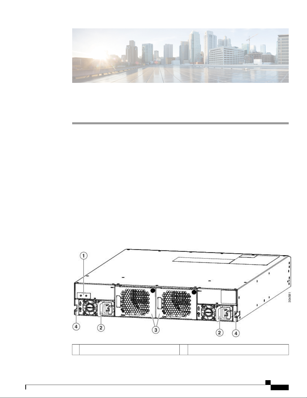
The following figure shows the hardware features seen on the power supply side of the chassis.
Figure 1: Hardware Features on the Power Supply Side of the Chassis
Fan modules (2)3Grounding Pad1
Cisco Nexus 9336PQ ACI-Mode Switch Hardware Installation Guide
1
Page 12
Ports
Overview
Power supplies (2) (AC power supply shown)2
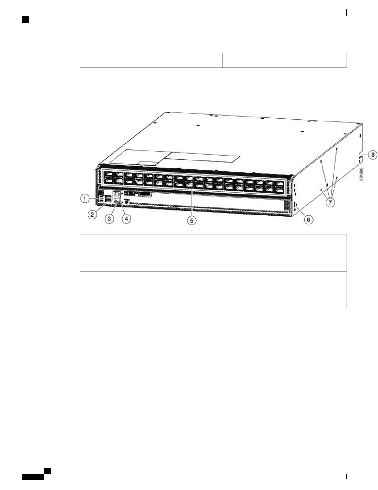
The following figure shows the hardware features seen from the port side of the chassis.
Figure 2: Hardware Features on the Port Side of the Chassis
Ports
36 40-Gigabit QSFP+ ports5Chassis LEDs1
Screw holes (2) for attaching a front-mount bracket for four-post racks
6USB ports2
(one bracket on each of two sides)
Notch in both sides of the chassis for locking the power supply end of
3
port (RJ-45 port)
7Out-of-band management
the chassis to the bottom support brackets
Console port (RJ232 port)4
The switch chassis includes the following types of ports:
40-Gigabit QSFP+ interface ports (36)
•
Console port (1)
•
Out-of-band management port (1)
•
USB flash-memory ports (2)
•
The interface ports support QSFP+ transceivers and are numbered from left to right. You use these ports to
connect the switch to Cisco Nexus 9300 switches in the ACI network that this switch belongs to. These ports
are numbered 1 to 36 from left to right.
Cisco Nexus 9336PQ ACI-Mode Switch Hardware Installation Guide
2
Page 13
Overview
The console port enables you to perform the initial setup of the switch.
The out-of-band management port enables you to manage switch operations after you set up the switch.
If you need to download or upload switch configurations on a flash drive, you can use the flash drive in one
of the two USB ports.
Supported Transceivers and Cables
To determine which transceivers and cables are supported by this switch, see the Cisco Transceiver Modules
Compatibility Information document.
Fan Modules
The switch supports two fan modules, which provide port-side intake or port-side exhaust airflow for cooling.
You can hot swap one of the fan modules during operations but must replace it within one minute. If you
cannot replace the fan module within one minute, then it is best to leave the failed fan module in the chassis
until you are ready to replace it.
The fan modules are labeled FAN 1 on the left and FAN 2 on the right.
Supported Transceivers and Cables
Note
The switch must run with all of its power supply and fan modules taking in cooling air from a cold aisle
and exhausting to a hot aisle. If they take in air from the hot aisle, the switch can overheat and shut down.
All fan and power supply modules must use the same direction of airflow.
Power Supply Modules
The switch has two power supply slots labeled PS1 on the left and PS2 on the right. You can mix any of the
following power supplies in those slots:
1200-W HVAC/HVDC power supplies with white coloring for dual-directional airflow
•
(N9K-PUV-1200W)
1200-W port-side exhaust AC power supply with blue coloring and NEBS compliance
•
(NXA-PAC-1200W-PE)
1200-W port-side intake AC power supply with burgundy coloring and NEBS compliance
•
(NXA-PAC-1200W-PI)
1200-W port-side exhaust AC power supply with blue coloring (N9K-PAC-1200W-B)
•
1200-W port-side intake AC power supply with burgundy coloring (N9K-PAC-1200W)
•
930-W DC power supplies with green coloring for port-side intake airflow (UCSC-PSU-930WDC)
•
930-W DC power supplies with gray coloring for port-side exhaust airflow (UCS-PSU-6332-DC)
•
The switch requires one power supply for its operations and a second power supply for power redundancy.
You can hot swap one of the power supplies during operations but otherwise must always have two power
supplies (or one power supply and one blank faceplate) installed in the chassis to maintain the designed airflow.
Cisco Nexus 9336PQ ACI-Mode Switch Hardware Installation Guide
3
Page 14

Power Supply Modules
Overview
Caution
The switch must run with all of its power supply and fan modules taking in cooling air from a cold aisle
and exhausting to a hot aisle. If they take in air from the hot aisle, the switch can overheat and shut down.
All power supply and fan modules must use the same direction of airflow.
Cisco Nexus 9336PQ ACI-Mode Switch Hardware Installation Guide
4
Page 15

CHAPTER 2
Preparing the Site
Temperature Requirements, page 5
•
Humidity Requirements, page 5
•
Altitude Requirements, page 6
•
Dust and Particulate Requirements, page 6
•
Minimizing Electromagnetic and Radio Frequency Interference, page 6
•
Shock and Vibration Requirements, page 7
•
Grounding Requirements, page 7
•
Planning for Power Requirements, page 7
•
Airflow Requirements, page 8
•
Rack and Cabinet Requirements, page 9
•
Clearance Requirements, page 10
•
Temperature Requirements
The switch requires an operating temperature of 32 to 104° F (0 to 40° C). If the switch is not operating, the
temperature must be between –40 to 158° F (–40 to 70° C).
Humidity Requirements
High humidity can cause moisture to enter the switch. Moisture can cause corrosion of internal components
and degradation of properties such as electrical resistance, thermal conductivity, physical strength, and size.
The switch is rated to operate at 8 to 80 percent relative humidity, with a humidity gradation of 10 percent
per hour. For nonoperating conditions, the switch can withstand from 5 to 95 percent relative humidity.
Buildings in which the climate is controlled by air-conditioning in the warmer months and by heat during the
colder months usually maintain an acceptable level of humidity for the switch equipment. However, if the
switch is located in an unusually humid location, you should use a dehumidifier to maintain the humidity
within an acceptable range.
Cisco Nexus 9336PQ ACI-Mode Switch Hardware Installation Guide
5
Page 16

Altitude Requirements
Altitude Requirements
If you operate a switch at a high altitude (low pressure), the efficiency of forced and convection cooling is
reduced and can result in electrical problems that are related to arcing and corona effects. This condition can
also cause sealed components with internal pressure, such as electrolytic capacitors, to fail or to perform at a
reduced efficiency. This switch is rated to operate at altitudes from 0 to 13,123 feet (0 to 4,000 meters).
Dust and Particulate Requirements
Exhaust fans cool power supplies and system fans cool switches by drawing in air and exhausting air out
through various openings in the chassis. However, fans also ingest dust and other particles, causing contaminant
buildup in the switch and increased internal chassis temperature. A clean operating environment can greatly
reduce the negative effects of dust and other particles, which act as insulators and interfere with the mechanical
components in the switch.
In addition to regular cleaning, follow these precautions to avoid contamination of your switch:
Preparing the Site
Do not permit smoking near the switch.
•
Do not permit food or drink near the switch.
•
Minimizing Electromagnetic and Radio Frequency Interference
Electromagnetic interference (EMI) and radio frequency interference (RFI) from the switch can adversely
affect other devices such as radio and television (TV) receivers operating near the switch. Radio frequencies
that emanate from the switch can also interfere with cordless and low-power telephones. Conversely, RFI
from high-power telephones can cause spurious characters to appear on the switch monitor.
RFI is defined as any EMI with a frequency above 10 kHz. This type of interference can travel from the switch
to other devices through the power cable and power source or through the air as transmitted radio waves. The
Federal Communications Commission (FCC) publishes specific regulations to limit the amount of EMI and
RFI that can be emitted by computing equipment. Each switch meets these FCC regulations.
To reduce the possibility of EMI and RFI, follow these guidelines:
Cover all open expansion slots with a blank filler plate.
•
Always use shielded cables with metal connector shells for attaching peripherals to the switch.
•
When wires are run for any significant distance in an electromagnetic field, interference can occur between
the field and the signals on the wires with the following implications:
Bad wiring can result in radio interference emanating from the plant wiring.
•
Strong EMI, especially when it is caused by lightning or radio transmitters, can destroy the signal drivers
•
and receivers in the chassis and even create an electrical hazard by conducting power surges through
lines into equipment.
Cisco Nexus 9336PQ ACI-Mode Switch Hardware Installation Guide
6
Page 17
Preparing the Site
Shock and Vibration Requirements
Note
Caution
To predict and prevent strong EMI, you might need to consult experts in radio frequency interference
(RFI).
The wiring is unlikely to emit radio interference if you use twisted-pair cable with a good distribution of
grounding conductors. If you exceed the recommended distances, use a high-quality twisted-pair cable with
one ground conductor for each data signal when applicable.
If the wires exceed the recommended distances, or if wires pass between buildings, give special
consideration to the effect of a lightning strike in your vicinity. The electromagnetic pulse caused by
lightning or other high-energy phenomena can easily couple enough energy into unshielded conductors
to destroy electronic switches. You might want to consult experts in electrical surge suppression and
shielding if you had similar problems in the past.
Shock and Vibration Requirements
The switch has been shock- and vibration-tested for operating ranges, handling, and earthquake standards.
Grounding Requirements
The switch is sensitive to variations in voltage supplied by the power sources. Overvoltage, undervoltage,
and transients (or spikes) can erase data from the memory or cause components to fail. To protect against
these types of problems, ensure that there is an earth-ground connection for the switch. You can connect the
grounding pad on the switch either directly to the earth-ground connection or to a fully bonded and grounded
rack.
You must provide the grounding cable to make this connection, but you can connect the grounding wire to
the switch using a grounding lug that ships with the switch. Size the grounding wire to meet local and national
installation requirements. Depending on the power supply and system, a 12-AWG to 6-AWG copper conductor
is required for U.S. installations (for those installations, we recommend that you use commercially available
6-AWG wire). The length of the grounding wire depends on the proximity of the switch to proper grounding
facilities.
Note
You automatically ground the power supplies when you connect them to power sources. You must also
connect the chassis to the facility earth ground.
Planning for Power Requirements
The switch includes two power supplies (1-to-1 redundancy with current sharing) in one of the following
combinations (all power supplies must have the same airflow direction as the fan modules):
Two 1200-W HVAC/HVDC power supplies
•
Cisco Nexus 9336PQ ACI-Mode Switch Hardware Installation Guide
7
Page 18
Airflow Requirements
Two 1200-W NEBS-compliant AC power supplies
•
Two 1200-W standard AC power supplies
•
Two 930-W DC power supplies
•
Any combination of the above power supplies
•
Preparing the Site
Note
Note
For n+1 redundancy, you must provide power to both power supplies. For n+n redundancy, you must
provide power to both power supplies and each power supply must be connected to a different power
source.
The power supplies are rated to output up to 1200 W (AC, NEBS-compliant AC, and HVAC/HVDC power
supplies) or up to 930 W (DC power supplies), but the switch requires less than those amounts of power from
the power supply. To operate the switch you must provision enough power from the power source to cover
the requirements of both the switch and a power supply. Typically, this switch and a power supply require
about 400 W of power input from the power source, but you must provision as much as 660 W power input
from the power source to cover peak demand.
To minimize the possibility of circuit failure, make sure that each power-source circuit used by the switch is
dedicated to the switch.
For the AC power cables that you can use with this switch, see Power Cord Specifications, on page 47.
For DC power cables, the recommended wire gauge is 8 AWG and the minimum wire gauge is 10 AWG.
Airflow Requirements
The switch is designed to be positioned with its ports in either the front or the rear of the rack depending on
your cabling and maintenance requirements. Depending on which side of the switch faces the cold aisle, you
must have fan and power supply modules that move the coolant air from the cold aisle to the hot aisle in one
of the following ways:
• Port-side exhaust airflow—Coolant air enters the chassis through the fan and power supply modules in
the cold aisle and exhausts through the port end of the chassis in the hot aisle.
• Port-side intake airflow—Coolant air enters the chassis through the port end in the cold aisle and exhausts
through the fan and power supply modules in the hot aisle.
• Dual-directional airflow—The airflow direction of the power supplies is determined by the airflow
direction of the fan modules.
You can identify the airflow direction of each fan and power supply module by its coloring as follows:
Blue coloring indicates port-side exhaust airflow.
•
Burgundy coloring indicates port-side intake airflow.
•
Gray coloring on DC power supplies indicates port-side exhaust airflow.
•
Green coloring on DC power supplies indicates port-side intake airflow.
•
Cisco Nexus 9336PQ ACI-Mode Switch Hardware Installation Guide
8
Page 19
Preparing the Site
Rack and Cabinet Requirements
White coloring on HVAC/HVDC power supplies indicates dual direction airflow.
•
Note
To prevent the switch from overheating and shutting down, you must position the air intake for the switch
in a cold aisle, and all of the fan and power supply modules must have the same direction of airflow (even
if their coloring is different).
Rack and Cabinet Requirements
You can install the following types of racks or cabinets for your switch:
Standard perforated cabinets
•
Solid-walled cabinets with a roof fan tray (bottom-to-top cooling)
•
Standard open four-post Telco racks
•
To correctly install the switch in a cabinet that is located in a hot-aisle/cold-aisle environment, you should fit
the cabinet with baffles to prevent exhaust air from recirculating into the chassis air intake.
Work with your cabinet vendors to determine which of their cabinets meet the following requirements or see
the Cisco Technical Assistance Center (TAC) for recommendations:
Use a standard 19-inch (48.3-cm), four-post Electronic Industries Alliance (EIA) cabinet or rack with
•
mounting rails that conform to English universal hole spacing per section 1 of the ANSI/EIA-310-D-1992
standard.
The depth of a four-post rack must be 24 to 32 inches (61.0 to 81.3 cm) between the front and rear
•
mounting brackets.
Warning
Required clearances between the chassis and the edges of its rack or the interior of its cabinet are as
•
follows:
4.5 inches (11.4 cm) between the front of the chassis and the interior of the cabinet (required for
◦
cabling).
3.0 inches (7.6 cm) between the rear of the chassis and the interior of the cabinet (required for
◦
airflow in the cabinet if used).
No clearance is required between the chassis and the sides of the rack or cabinet (no side airflow).
◦
Additionally, you must have power receptacles located within reach of the power cords used with the switch.
For the power cord specifications, see the Power Cord Specifications.
Statement 1048—Rack Stabilization
Stability hazard. The rack stabilizing mechanism must be in place, or the rack must be bolted to the floor
before you slide the unit out for servicing. Failure to stabilize the rack can cause the rack to tip over.
Cisco Nexus 9336PQ ACI-Mode Switch Hardware Installation Guide
9
Page 20
Clearance Requirements
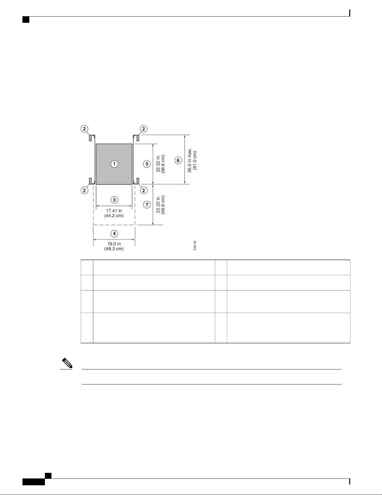
Clearance Requirements
You must provide the chassis with adequate clearance between the chassis and any other rack, device, or
structure so that you can properly install the chassis, route cables, provide airflow, and maintain the switch.
For the clearances required for an installation of this chassis in a four-post rack, see the following figure.
Figure 3: Clearances Required for a Four-Post Rack Installation
Preparing the Site
Width of the front clearance area (this equals
4
the width of the chassis with two rack-mount
brackets attached to it)
Both the front and rear of the chassis must be open to both aisles for airflow.Note
Depth of the chassis5Chassis1
Maximum extension of the bottom-support rails6Vertical rack-mount posts and rails2
Depth of the front clearance area (this equals the
7Chassis width3
depth of the chassis)
Cisco Nexus 9336PQ ACI-Mode Switch Hardware Installation Guide
10
Page 21

Installing the Chassis
Preparing to Install the Switch, page 11
•
Installing a Rack or Cabinet, page 13
•
Unpacking and Inspecting the Switch, page 14
•
Installing the Chassis in a Four-Post Rack, page 15
•
Grounding the Chassis, page 21
•
Powering Up the Switch, page 23
•
Preparing to Install the Switch
Before you install, operate, or service the switch, see the Regulatory, Compliance, and Safety Information for
the Cisco Nexus 9000 Series for important safety information.
CHAPTER 3
Warning
Statement 1071—Warning Definition
IMPORTANT SAFETY INSTRUCTIONS
This warning symbol means danger. You are in a situation that could cause bodily injury. Before you
work on any equipment, be aware of the hazards involved with electrical circuitry and be familiar with
standard practices for preventing accidents. Use the statement number provided at the end of each warning
to locate its translation in the translated safety warnings that accompanied this device.
SAVE THESE INSTRUCTIONS
The switch can be installed in the following types of racks using a rack-mount kit shipped with the switch:
Open EIA rack
•
Perforated EIA cabinet
•
The rack or cabinet that you use must meet the requirements listed in Rack Specifications, on page 43.
You can order the switch chassis with port-side-intake or port-side exhaust airflow. Port-side intake airflow
enters the chassis through the port side (I/O module side) of the chassis and exhausts through the fan and
Cisco Nexus 9336PQ ACI-Mode Switch Hardware Installation Guide
11
Page 22

Preparing to Install the Switch
power supply modules on the opposite end of the chassis. Port-side exhaust airflow enters the chassis through
the fan modules and exhausts through the port side of the chassis.
When lifting the chassis, use each of the following guidelines:
Disconnect any cables attached to the switch.
•
Ensure that your footing is solid and the weight of the switch is evenly distributed between your feet.
•
Lift the switch slowly, keeping your back straight. Lift with your legs, not with your back. Bend at the
•
knees, not at the waist.
When installing the switch, follow these guidelines:
Record switch and installation information in Site Preparation and Maintenance Records, on page 57
•
as you install and configure the switch.
Ensure that there is adequate space around the switch to allow for servicing the switch and for adequate
•
airflow (see Clearance Requirements, on page 10 for the switch specifications).
Ensure that the switch is going to be positioned with its air intake side positioned in the cold aisle and
•
its air exhaust positioned in the hot aisle. This enables the switch to be cooled properly. If the air intake
is positioned in a hot aisle, the switch can overheat and shutdown.
Installing the Chassis
Ensure that the rack or cabinet meets the requirements listed in Rack Specifications, on page 43.
•
Jumper power cords are available for use in a cabinet.Note
Ensure that the chassis can be adequately grounded. If the switch is not mounted in a grounded rack,
•
we recommend connecting both the system ground on the chassis and the power supply ground directly
to an earth ground.
Ensure that the site power meets the power requirements listed in System Specifications. If available,
•
you can use an uninterruptible power supply (UPS) to protect against power failures.
Caution
Avoid UPS types that use ferroresonant technology. These UPS types can become
unstable with switches that have substantial current draw fluctuations because of
fluctuating data traffid patterns.
Ensure that circuits are sized according to local and national codes and meet the requirements of the
•
switch (see Planning for Power Requirements, on page 7 for the switch requirements).
Caution
To prevent loss of input power, ensure that the total maximum loads on the circuits
supplying power to the switch are within the current ratings for wiring and breakers.
Depending on your power redundancy needs, have outlets or terminals for one or two power sources
•
close to the rack as follows:
For no power redundancy, have one power source.
◦
For n+1 redundancy, have one or two power sources.
◦
Cisco Nexus 9336PQ ACI-Mode Switch Hardware Installation Guide
12
Page 23

Installing the Chassis
Installing a Rack or Cabinet
For n+n redundancy, have two power sources.
◦
Use the following screw torques when installing the switch:
•
Captive screws: 4 in-lb (0.45 N·m)
◦
M3 screws: 4 in-lb (0.45 N·m)
◦
M4 screws: 12 in-lb (1.36 N·m)
◦
M6 screws: 40 in-lb (4.5 N·m)
◦
10-32 screws: 20 in-lb (2.26 N·m)
◦
12-24 screws: 30 in-lb (3.39 N·m)
◦
Before beginning the installation, ensure that you have the following items available in addition to the switch
and accessory kit:
Eight customer supplied 12-24 or 10-32 screws (required for attaching slider rails and mounting brackets
•
to the mounting rails)
Number 1 and number 2 Phillips screwdrivers with torque capability
•
3/16-inch wide flat screwdriver
•
Tape measure and level
•
ESD wrist strap or other grounding device
•
Antistatic surface
•
Grounding cable (6 AWG recommended), sized according to local and national installation requirements;
•
the required length depends on the proximity of the switch to proper grounding facilities
Crimping tool large enough to accommodate the girth of the grounding lug
•
Wire-stripping tool
•
Installing a Rack or Cabinet
Before you install the switch, you must install a standard four-post, 19-inch (48.3-cm) EIA data center rack
(or a cabinet that contains such a rack) that meets the requirements listed in Rack and Cabinet Requirements,
on page 9.
Warning
Statement 1048—Rack Stabilization
Stability hazard. The rack stabilizing mechanism must be in place, or the rack must be bolted to the floor
before you slide the unit out for servicing. Failure to stabilize the rack can cause the rack to tip over.
Cisco Nexus 9336PQ ACI-Mode Switch Hardware Installation Guide
13
Page 24

Unpacking and Inspecting the Switch
Installing the Chassis
Step 1
Step 2
Step 3
Warning
Bolt the rack to the subfloor before moving the chassis onto it.
If the rack has bonded construction, connect it to the earth ground. This action enables you to easily ground the switch
and its components and to ground your electrostatic discharge (ESD) wrist strap to prevent discharge damage when you
handle ungrounded components during installation.
If you need access to the source power at the rack, include one of the following:
Note
Statement 1018—Supply Circuit
Take care when connecting units to the supply circuit so that wiring is not overloaded.
For AC power, include an AC circuit that meets the power specifications of the switch (see Planning for Power
•
Requirements, on page 7). This circuit must include receptacles that match your local and national requirements
and match the needs of the power cable used with the power supply unit.
For DC power, include a DC circuit that meets the power specifications of the switch (see Planning for Power
•
Requirements, on page 7). This circuit must include a circuit breaker so that you can safely connect the power
cables to the power supply.
If you are using the combined mode or n+1 redundancy mode, you need only one power source. If you are using
the n+n redundancy mode, you need two power sources (one power source for each power supply).
Unpacking and Inspecting the Switch
The switch is thoroughly inspected before shipment. If any damage occurred during transportation or any
items are missing, contact your customer service representative immediately.
Keep the shipping container in case the chassis requires shipping in the future.Note
Before You Begin
To protect the electrical components in the switch, you must wear a grounded ESD strap and handle modules
by only their handles and carrier edges. To ground the ESD strap, make sure that it is attached to an earth
ground, a grounded chassis, or grounded rack.
Step 1
Compare the shipment to the equipment list provided by your customer service representative and verify that you have
received all items, including the following:
Grounding lug kit
•
Rack-mount kit
•
ESD wrist strap
•
Cisco Nexus 9336PQ ACI-Mode Switch Hardware Installation Guide
14
Page 25

Installing the Chassis
Cables with connectors
•
Any optional items ordered
•
Installing the Chassis in a Four-Post Rack
Step 2
Step 3
Check for damage and report any discrepancies or damage to your customer service representative. Have the following
information ready:
Invoice number of shipper (see packing slip)
•
Model and serial number of the damaged unit
•
Description of damage
•
Effect of damage on the installation
•
Check to be sure that all of the fan and power supply modules have the expected direction of airflow. Burgundy coloring
on fan and AC power supply modules indicates port-side intake airflow, and blue coloring indicates port-side exhaust
airflow. DC power supply modules have either port-side intake airflow (green coloring) or port-side exhaust (grey
coloring). HVAC/HVDC power supply modules have white coloring to indicate that they automatically use the same
airflow direction used by the fan modules.
Installing the Chassis in a Four-Post Rack
Before you install the chassis, be sure that the rack is fully secured to the data center floor.
You must attach the bottom support rails to the rack and attach the mounting brackets to the chassis before
mounting the chassis in the rack.
Attaching the Bottom-Support Rails to the Rack
The switch chassis that you are installing ships with two adjustable bottom-support rails that you can attach
to a four-post rack to hold the chassis. Each of these bottom-support rails has two pieces—one that slides into
the other so that you can adjust them to fit racks with front and rear mounting posts that are spaced less than
36 inches (91 cm). On each bottom-support rail, the rail half that slides into the other rail includes a chassis
stop that fits into the module end of the chassis. Depending on direction of the chassis airflow, you need to
position the rail half with the chassis stop so that the fan and power supply modules end up in the appropriate
aisle as follows:
Port-side intake (burgundy coloring for fan modules) airflow requires that the bottom-support rail with
•
the chassis stop be located on the hot aisle side of the rack.
Port-side exhaust (blue coloring for fan modules) airflow requires that the bottom-support rail with the
•
chassis stop be located on the cold aisle side of the rack.
Warning
Statement 1074—Comply with Local and National Electrical Codes
Installation of the equipment must comply with local and national electrical codes.
Cisco Nexus 9336PQ ACI-Mode Switch Hardware Installation Guide
15
Page 26

Attaching the Bottom-Support Rails to the Rack
Before You Begin
Before you can install the bottom support rails for the chassis, you must do the following:
Verify that a four-post rack or cabinet is installed.
•
If any other devices are stored in the rack or cabinet, verify that the heavier switches are installed below
•
lighter switches and that there is at least rack units open to install the switch.
Verify that the bottom-support rails kit is included in the switch accessory kit.
•
Verify that you have 8 screws for attaching the bottom support brackets to the racks (typically M6 x 10
•
mm screws or the screw appropriate for the vertical mounting rails on the rack.
Installing the Chassis
Step 1
Step 2
Step 3
Step 4
Step 5
Warning
Statement 1006—Chassis Warning for Rack-Mounting and Servicing
To prevent bodily injury when mounting or servicing this unit in a rack, you must take special precautions
to ensure that the system remains stable. The following guidelines are provided to ensure your safety:
This unit should be mounted at the bottom of the rack if it is the only unit in the rack.
•
When mounting this unit in a partially filled rack, load the rack from the bottom to the top with
•
the heaviest component at the bottom of the rack.
If the rack is provided with stabilizing devices, install the stabilizers before mounting or servicing
•
the unit in the rack.
Look at the fan and power supply modules installed in the chassis to determine how you must position the bottom-support
rails on the rack.
If the fan modules have blue coloring (port-side exhaust modules), you must position the bottom support rails so
•
that the chassis stop is positioned by the cold aisle.
If the fan modules have burgundy (port-side intake modules), you must position the bottom support rails so that
•
the chassis stop is positioned by the hot aisle.
Separate the two sliders that make up one bottom-support rail and position the half with the chassis stop by the appropriate
aisle for the fan and power supply modules. Also make sure that there is at least rack units open above the bottom-support
rails so that you can easily install the chassis.
Use two customer-supplied screws (typically M6 x 10 mm screws) to attach the bottom-support rail half to the vertical
mounting rails on the rack post. Tighten each screw to the appropriate torque setting for the screws (for M6 x 10 mm
screws, use 40 in. lbs [4.5 N·m] of torque).
Slide the other half of the bottom-support rail onto the attached half of the rail set and use two customer supplied screws
(typically M6 x 10 mm screws) to secure that portion to the vertical mounting rails on the rack. Tighten each screw to
the appropriate torque setting for the screws (for M6 x 10 mm screws, use 40 in. lbs [4.5 N·m] of torque).
Repeat Steps 2 and 3 to attach the other expanding bottom-support rails to the other side of the rack.
Note
Check the two installed bottom support rails to be sure that both have their chassis stops by the same aisle (either
both by the hot aisle or both by the cold aisle) and that both rails are level and level with each other. If they are
not level, adjust the higher rail down to the level of the lower rail.
Cisco Nexus 9336PQ ACI-Mode Switch Hardware Installation Guide
16
Page 27

Installing the Chassis
What to Do Next
You are ready to install two front-mount brackets on the chassis.
Attaching Front-Mount Brackets to the Chassis
You need to attach a right-angled bracket to each side of the chassis. This bracket holds the chassis in place
on a four-post rack.
If you are installing the chassis in a two-post rack, see Attaching Center-Mount Brackets to the ChassisNote
Before You Begin
You must have the following tools and equipment:
•
Attaching Front-Mount Brackets to the Chassis
Step 1
Manual Phillips-head torque screwdriver
◦
Front-mount brackets (2) and screws (4) (found inside the switch accessory kit)
◦
Align the two holes in one side of one of two front-mount brackets to two holes on the left or right side of the chassis
(see the following figure).
Be sure that the other side of the bracket is facing toward the front (port end) of the chassis.
Figure 4: Aligning and Attaching Front-Mount Brackets to the Sides of the Chassis
Cisco Nexus 9336PQ ACI-Mode Switch Hardware Installation Guide
17
Page 28

Installing the Chassis in a Four-Post Rack
1
two screw holes in the chassis and one screw hole
facing the front (port side) of the chassis.
Installing the Chassis
Two M4 x 6 mm screws used to fasten the bracket to
2Front-mount bracket with two screw holes aligned to
the chassis.
Step 2
Step 3
Use two M4 x 6 mm screws to attach the bracket to the chassis. Tighten each screw to 11 to 15 in-lb (1.2 to 1.7 N·m).
Repeat Steps 1 and 2 to attach the second center-mount bracket to the other side of the chassis.
What to Do Next
You are ready to mount the chassis to the four-post rack.
Installing the Chassis in a Four-Post Rack
You need to slide the chassis onto the bottom-support rails so that the power supply end locks onto the chassis
stops at the end of the rails and so that the front-mount brackets on the chassis come into contact with the
front-mount rails on the rack.
Warning
Warning
Statement 1074—Comply with Local and National Electrical Codes
Installation of the equipment must comply with local and national electrical codes.
Statement 1032—Lifting the Chassis
To prevent personal injury or damage to the chassis, never attempt to lift or tilt the chassis using the
handles on modules (such as power supplies, fans, or cards); these types of handles are not designed to
support the weight of the unit.
Before You Begin
Make sure that the four-post rack is properly installed and secured to the concrete subfloor.
•
Make sure that the bottom-support rails are installed so that the fan modules will be in the appropriate
•
aisle as follows:
Burgundy (port-side intake airflow) fan modules are positioned in a hot aisle (the chassis stop on
◦
the bottom-support rails is positioned by the hot aisle).
Blue colored (port-side exhaust airflow) fan modules are positioned in a cold aisle (the chassis
◦
stop on the bottom-support rails is positioned by the cold aisle).
Make sure that two front-mount brackets are securely fastened to the sides of the chassis at the port end.
•
Make sure that you have two customer-supplied rack-mount screws (M6 x 10 mm or appropriate screw
•
for the vertical mounting rails on the rack).
Cisco Nexus 9336PQ ACI-Mode Switch Hardware Installation Guide
18
Page 29

Installing the Chassis
Installing the Chassis in a Four-Post Rack
Step 1
Warning
Statement 1006—Chassis Warning for Rack-Mounting and Servicing
To prevent bodily injury when mounting or servicing this unit in a rack, you must take special precautions
to ensure that the system remains stable. The following guidelines are provided to ensure your safety:
This unit should be mounted at the bottom of the rack if it is the only unit in the rack.
•
When mounting this unit in a partially filled rack, load the rack from the bottom to the top with
•
the heaviest component at the bottom of the rack.
If the rack is provided with stabilizing devices, install the stabilizers before mounting or servicing
•
the unit in the rack.
Slide the power supply end of the chassis onto the bottom-support rails that are installed on the rack.
Be sure that the sides of the chassis by the power supplies clips into the chassis stops on the bottom-support rails and
the front-mount brackets come in contact with the rack (see the following figure).
Cisco Nexus 9336PQ ACI-Mode Switch Hardware Installation Guide
19
Page 30

Installing the Chassis in a Four-Post Rack
Installing the Chassis
Note
If the bottom-support rails are extended a long distance, they can bend outwards slightly when you install the
chassis and the chassis stops at the far end of the rails might not fit into the end of the chassis. If this happens,
press the side rails toward the sides of the chassis so that the chassis stops can go inside the chassis and hold it
in place on the rack.
Figure 5: Sliding the Chassis onto the Bottom-Support Rails
Receiving hole on each side of the chassis for the
1
bottom-support rails so that the chassis locks onto the
3Slide the power-supply end of the chassis onto the
chassis stops on the bottom-support rails.
chassis stops at the end of the rails.
Customer-supplied rack-mount screw (M6 x 10 mm
2
the aisle required for the fan and power supply
modules).
Cisco Nexus 9336PQ ACI-Mode Switch Hardware Installation Guide
20
4Chassis stops for holding the chassis (positioned by
screw or other screw appropriate for the rack) used
to secure each side of the chassis to the rack.
Page 31

Installing the Chassis
Grounding the Chassis
Step 2
Use a customer-supplied rack-mount screw (an M6 x 10 mm screw or other appropriate screw for the rack) to attach
each of the two mounting brackets on the chassis to the rack and tighten each screw to the appropriate torque setting for
the screw (for M6 x 10 mm screws, use 40 in-lbs [4.5 N·m] of torque).
Grounding the Chassis
The switch is grounded when you connect the chassis and the power supplies to the earth ground in both of
the following ways:
You connect the chassis (at its grounding pad) to the data center ground. If the rack is fully-bonded and
•
grounded, you can ground the switch by connecting it to the data center ground indirectly through the
rack. Otherwise, you must connect the chassis directly to the data center ground.
Note
You connect each power supply to the data center ground.
•
The chassis ground connection is active even when the power supply modules have not
been grounded or connected to the switch.
AC power supplies are automatically grounded when you connect the power supply to an AC
◦
power source (see Powering Up the Switch, on page 23).
Warning
Warning
DC power supplies are grounded when you connect the ground cable to the power source ground
◦
terminal while also connecting the positive and negative wires to their power source terminals (see
Powering Up the Switch, on page 23).
Statement 1024—Ground Conductor
This equipment must be grounded. Never defeat the ground conductor or operate the equipment in the
absence of a suitably installed ground conductor. Contact the appropriate electrical inspection authority
or an electrician if you are uncertain that suitable grounding is available.
Statement 1046—Installing or Replacing the Unit
When installing or replacing the unit, the ground connection must always be made first and disconnected
last.
Before You Begin
Before you can ground the chassis, you must have a connection to the earth ground for the data center building.
If you installed the switch chassis into a bonded rack (see the rack manufacturer's instructions for more
information) that now has a connection to the data center earth ground, you can ground the chassis by connecting
Cisco Nexus 9336PQ ACI-Mode Switch Hardware Installation Guide
21
Page 32

Grounding the Chassis
its grounding pad to the rack. Otherwise, you must connect the chassis grounding pad directly to the data
center ground.
Installing the Chassis
Step 1
Step 2
Use a wire-stripping tool to remove approximately 0.75 inch (19 mm) of the covering from the end of the grounding
wire.
Insert the stripped end of the grounding wire into the open end of the grounding lug, and use a crimping tool to crimp
the lug to the wire (see Callout 2 in the following figure). Verify that the ground wire is securely attached to the grounding
lug by attempting to pull the wire out of the crimped lug.
Figure 6: Grounding the Chassis
Step 3
Step 4
Two M4 screws used to secure the grounding lug to
3Chassis grounding pad1
the chassis
Grounding cable, with 0.75 in. (19 mm) of insulation
2
stripped from one end, inserted into the grounding
lug and crimped in place
Secure the grounding lug to the chassis grounding pad with two M4 screws (see Callouts 1 and 3 in the previous figure),
and tighten the screws to 11 to 15 in-lb (1.24 to 1.69 N·m) of torque.
Prepare the other end of the grounding wire and connect it to an appropriate grounding point in your site to ensure an
adequate earth ground for the switch. If the rack is fully bonded and grounded, connect the grounding wire as explained
in the documentation provided by the vendor for the rack.
Cisco Nexus 9336PQ ACI-Mode Switch Hardware Installation Guide
22
Page 33

Installing the Chassis
Powering Up the Switch
To power up the switch, you must connect one or two power supplies to one or two power sources. The number
of power supplies and power sources used depends on the type of power redundancy that you require as
follows:
For no power redundancy, connect only one power supply to a power source.
•
For n+1 redundancy, connect two power supplies to one or two power sources.
•
For n+n redundancy, connect two power supplies to two different power sources.
•
Powering Up the Switch
Warning
Warning
Warning
Warning
Statement 7012—Equipment Interfacing with AC Power Ports
This equipment shall be connected to AC mains provided with a surge protective device (SPD) at the
service equipment complying with NFPA 70, the National Electrical Code (NEC).
Statement 1004—Installation Instructions
Read the installation instructions before connecting the system to the power source.
Statement 1018—Supply Circuit
Take care when connecting units to the supply circuit so that wiring is not overloaded.
Statement 1029—Blank Faceplates and Cover Panels
Blank faceplates and cover panels serve three important functions: they prevent exposure to hazardous
voltages and currents inside the chassis; they contain electromagnetic interference (EMI) that might disrupt
other equipment; and they direct the flow of cooling air through the chassis. Do not operate the system
unless all cards, faceplates, front covers, and rear covers are in place.
Before You Begin
Step 1
Switch installed in a rack and connected to an earth ground
•
Recommended power cable for your nation or region
•
Power source with the required amperage located within reach of the power cable being used
•
Connect each power supply to a power source as follows:
Connecting an AC power supply:
•
Using the recommended power cable for your country or region (see Power Cord Specifications, on page 47),
1
connect the C13 plug on the power cable to the power receptacle on the power supply.
Cisco Nexus 9336PQ ACI-Mode Switch Hardware Installation Guide
23
Page 34

Powering Up the Switch
Rotate the cable retention clip on the power supply over the C13 plug to prevent accidental unplugging of the
2
cable.
Connect the other end of the power cable to the AC power source.
3
4
Verify that the LED is on and green.
If the LED is off, check the AC power source circuit breaker to be sure that it is turned on.
Connecting a DC power supply:
•
Verify that the circuit breaker for the DC power source you are connecting is turned off.
1
Remove the DC power connector block from the power supply by doing the following:
2
a
b
Strip 0.6 inches (15 mm) of insulation off the DC wires that you are using.
3
Installing the Chassis
Push the orange plastic button on the top of the connector block inward toward the power supply.
Pull the connector block out of the power supply.
Orient the connector as shown in the following figure with the orange plastic button on top.
4
Figure 7: Wiring a 930W -48VDC Power Supply Connector Block
-48V (-DC) cable4Wire retainer lever1
Grounding cable (8 AWG recommended)5Orange plastic button on top of the connector2
-48V Return (+DC) cable3
Use a small screwdriver to depress the spring-loaded wire retainer lever on the lower spring-cage wire connector.
5
Insert your green (ground) wire into the aperture and then release the lever.
Use a small screwdriver to depress the spring-loaded wire retainer lever on the middle spring-cage wire connector.
6
Insert your black (DC negative) wire into the aperture and then release the lever.
Use a small screwdriver to depress the spring-loaded wire retainer lever on the upper spring-cage wire connector.
7
Insert your red (DC positive) wire into the aperture and then release the lever.
Cisco Nexus 9336PQ ACI-Mode Switch Hardware Installation Guide
24
Page 35

Installing the Chassis
8
Connecting an HVAC/HVDC power supply:
•
1
2
Powering Up the Switch
Insert the connector block back into the power supply. Make sure that your red (DC positive) wire aligns with
the power supply label, "+ DC".
Note
If you require n+n redundancy, be sure that each power supply is powered by a different power source.
Using the recommended power cable for your country or region (see Power Cord Specifications, on page 47),
insert the Saf-D-Grid connector on the power cable to the power receptacle on the power supply until it clicks
in place.
Connect the other end of the power cable to the power source.
If connecting to an AC power source, plug the cable into the receptacle for the power source.
•
If connecting to a DC power source, do the following:
•
Verify that the power source is turned off at the circuit breaker located between the power source and
1
the terminals where you will connect the power cable.
Step 2
Connect each of the three wires in the power cable to the three terminals for the power source and
2
secure them with the terminal nuts. Make sure that the positive wire is attached to the positive terminal,
the negative wire is attached to the negative terminal, and the ground wire is attached to the ground
terminal.
If there is a safety cover for the terminals, place it over the terminals to prevent people from accidentally
3
touching the terminals when the power is on.
Turn the power on at the circuit breaker.
4
3
Verify that the LED is on and green.
If the LED is off, check the AC power source circuit breaker to be sure that it is turned on.
If you are connecting only one power supply, be sure that there is a blank faceplate in the open power supply slot.
Cisco Nexus 9336PQ ACI-Mode Switch Hardware Installation Guide
25
Page 36

Powering Up the Switch
Installing the Chassis
Cisco Nexus 9336PQ ACI-Mode Switch Hardware Installation Guide
26
Page 37

Connecting the Switch to the ACI Fabric
ACI Fabric Topology, page 27
•
Preparing to Connect to Other Devices, page 28
•
Connecting a Leaf Switch to an APIC, page 29
•
Connecting a Leaf Switch to a Spine Switch, page 30
•
Setting Up an Optional Console or Optional Out-Of-Band Management Interface, page 32
•
Maintaining Transceivers and Optical Cables, page 32
•
ACI Fabric Topology
The ACI fabric topology includes the following major components:
Application Centric Infrastructure Controller (APIC) appliance (cluster of APICs)
•
CHAPTER 4
Leaf switches (Cisco Nexus 93120TX, 93128TX, 9332PQ, 9372PX, 9372PX-E, 9372TX, 9396PX, and
•
9396TX switches)
Spine switches (Cisco Nexus 9336PQ, 9504, 9508, and 9516 switches)
•
Cisco Nexus 9336PQ ACI-Mode Switch Hardware Installation Guide
27
Page 38

Preparing to Connect to Other Devices
As shown in the following figure, each spine switch is connected to a downlink port on a leaf switch, which
is in turn uplinked to one or more APICs.
Figure 8: ACI Fabric Topology
Connecting the Switch to the ACI Fabric
Preparing to Connect to Other Devices
When preparing to connect the switch to leaf switchesspine switches and one or more APICs, consider the
following for each type of interface, and gather all of the required equipment before making the connections:
Cabling type required for each interface type
•
Distance limitations for each signal type
•
Additional interface equipment required
•
Cisco Nexus 9336PQ ACI-Mode Switch Hardware Installation Guide
28
Page 39

Connecting the Switch to the ACI Fabric
Connecting a Leaf Switch to an APIC
Note
When running power and data cables in overhead or subfloor cable trays, we strongly recommend that
you locate power cables and other potential noise sources as far away as practical from network cabling
that terminates on Cisco equipment. In situations where long parallel cable runs cannot be separated by
at least 3.3 feet (1 meter), we recommend that you shield any potential noise sources by housing them in
a grounded metallic conduit.
The optical transceivers that are not already assembled to their cables come separate from their cables. To
prevent these transceivers and their cables from being damaged, we recommend that you keep the transceivers
disconnected from their cables when installing them in ports and then insert the optical cable into the transceiver.
When removing transceivers from ports, remove their cables before removing the transceivers.
To maximize the effectiveness and life of your transceivers and optical cables, do the following:
Wear an ESD-preventative wrist strap that is connected to an earth ground whenever handling transceivers.
•
The switch is typically grounded when you install transceivers and provides an ESD port to which you
can connect your wrist strap. If you cannot find an ESD port, connect the wrist strap to an earth ground
(such as the grounding connection for the chassis).
Do not remove or insert a transceiver more often than necessary. Repeated removals and insertions can
•
shorten its useful life.
Keep the transceivers and fiber-optic cables clean and dust free to maintain high signal accuracy and to
•
prevent damage to the connectors. Attenuation (loss of light) increases with contamination and should
be kept below 0.35 dB.
Clean these parts before installing them to prevent dust from scratching the fiber-optic cable ends.
◦
Clean the connectors regularly; the required frequency of cleaning depends upon the environment.
◦
In addition, clean connectors if they are exposed to dust or accidentally touched. Both wet and dry
cleaning techniques can be effective; refer to your site's fiber-optic connection cleaning procedures.
Do not touch the ends of connectors. Touching the ends can leave fingerprints and cause other
◦
contamination.
Inspect routinely for dust and damage. If you suspect damage, clean and then inspect fiber ends under
•
a microscope to determine if damage has occurred.
Connecting a Leaf Switch to an APIC
You must downlink one or two (recommended for redundancy) Cisco Nexus 93120TX, 93128TX, 9332PQ,
9372PX, 9372PX-E, 9372TX, 9396PX, or 9396TX leaf switches running in ACI mode to each Application
Policy Infrastructure Controller (APIC) in your ACI fabric (each leaf switch can be connected to multiple
APICs). The type of interface cables and leaf switches that you connect to are determined by the type of virtual
interface card (VIC) installed on the APIC as follows:
The VIC1225 module supports optical transceivers, optical cables, and the Cisco Nexus 9396PX leaf
•
switch.
The VIC1225T module supports copper connectors, copper cables, and the Cisco Nexus 93128TX and
•
9396TX leaf switches.
Cisco Nexus 9336PQ ACI-Mode Switch Hardware Installation Guide
29
Page 40

Connecting a Leaf Switch to a Spine Switch
Before You Begin
The switch and APIC must be fully installed in their racks.
•
The switch and APIC must be grounded and powered up.
•
Connecting the Switch to the ACI Fabric
Step 1
Step 2
Connect an interface cable to one of the two ports on the virtual interface card (VIC) installed on the APIC. If the cable
is not already assembled to its transceivers, insert the transceiver into the VIC port and then connect the optical interface
cable to the transceiver.
For a VIC1225 optical module, use one of the following sets of transceivers and cables:
•
Cisco 10GBASE-LR transceivers (SFP-10G-LR) supporting a link length of up to 6.1 miles (10 km)
◦
Cisco 10GBASE-SR transceivers (SFP-10G-SR) supporting the following link lengths:
◦
Using 2000 MHz MMF (OM3) for up to 984 feet (300 m)
◦
Using 4700 MHz MMF (OM4) for up to 1312 feet (400 m)
◦
Cisco SFP+ Active Optical Cables (SFP-10G-AOCxM [where x=1, 2, 3, 5, 7, or 10 for lengths in meters])
◦
For transceiver specifications, see http://www.cisco.com/c/en/us/support/interfaces-modules/transceiver-modules/
products-installation-guides-list.html.
For a VIC1225T 10GBASE-T copper module, use 10GBASE-T cables with RJ-45 connectors.
•
Connect the other end of the interface cable to a downlink port on a leaf switch.
For a Cisco 10GBASE-LR or -SR transceiver and cable, insert the transceiver into a downlink optical port on a
•
leaf switch before connecting the cable to the transceiver.
For Cisco SFP+ Active Optical Cables, insert the transceiver on the cable into a downlink optical port on a leaf
•
switch.
For a 10GBASE-T copper cable, insert the RJ-45 connector on the cable into a downlink BASE-T port on a leaf
•
switch.
What to Do Next
If the APICs are also connected to the leaf switches, then the ACI fabric is ready to be automatically initiated.
Connecting a Leaf Switch to a Spine Switch
You must connect each Cisco Nexus 93120TX, 93128TX, 9332PQ, 9372PX, 9372PX-E, 9372TX, 9396PX,
or 9396TX leaf switch to every Cisco Nexus 9336PQ, 9504, 9508, or 9516 spine switch in the same ACI
fabric. The Cisco Nexus 93128TX allows for 8 connections (uplink ports 1 through 8) to spine switches, the
Cisco Nexus 9396PX and 9396TX switches allow up to 12 connections to spine switches, and the Cisco Nexus
93120TX, 9332PQ, 9372PX, 9372PX-E, 9372TX, and 9372TX-E switches allow up to 6 connections to spine
switches. To determine which transceivers and cables are supported by this switch, see http://www.cisco.com/
Cisco Nexus 9336PQ ACI-Mode Switch Hardware Installation Guide
30
Page 41

Connecting the Switch to the ACI Fabric
c/en/us/support/interfaces-modules/transceiver-modules/products-device-support-tables-list.html. To see the
transceiver specifications and installation information, see http://www.cisco.com/c/en/us/support/
interfaces-modules/transceiver-modules/products-installation-guides-list.html.
Connecting a Leaf Switch to a Spine Switch
Warning
Warning
Warning
Statement 1053—Class 1M Laser Radition
Class 1M laser radiation when open. Do not view directly with optical instruments.
Statement 1055—Class I and Class 1M Laser
Class I (CDRH) and Class 1M (IEC) laser products.
Statement 1056—Unterminated Fiber Cable
Invisible laser radiation may be emitted from the end of the unterminated fiber cable or connector. Do not
view directly with optical instruments. Viewing the laser output with certain optical instruments (for
example, eye loupes, magnifiers, and microscopes) within a distance of 100 mm may pose an eye hazard.
Before You Begin
The leaf and spine switches must be fully installed in their racks.
•
The leaf and spine switches must be grounded and powered up.
•
If you are using a Cisco Nexus 9504, 9508, or 9516 spine switch in the ACI fabric, it must have only
•
the 36-port 40-Gigabit ACI-spine I/O modules (N9K-X9736PQ). You cannot mix other I/O modules in
the same chassis when running in ACI mode.
Step 1
Step 2
Step 3
Step 4
Step 5
Step 6
For the transceivers with removable cables, make sure that the transceivers are separated from their interface cables.
Insert the appropriate transceiver into an active uplink port on the leaf switch.
Insert the same type of transceiver in the spine switch port on a X9736PQ I/O module.
For transceivers with removable cables, insert the interface cable into the open end of each of those transceivers.
Repeat Steps 1 through 4 for each spine switch in the ACI fabric.
The leaf switch is connected to each spine switch in the ACI fabric.
Repeat Steps 1 through 5 for each leaf switch in the ACI fabric.
Each leaf switch in the ACI fabric is connected to each spine switch in the network,
What to Do Next
If the APICs are also connected to the leaf switches, then the ACI fabric is ready to be automatically initiated.
Cisco Nexus 9336PQ ACI-Mode Switch Hardware Installation Guide
31
Page 42

Connecting the Switch to the ACI Fabric
Setting Up an Optional Console or Optional Out-Of-Band Management Interface
Setting Up an Optional Console or Optional Out-Of-Band
Management Interface
You can optionally set up a console or out-of-band management interface for monitoring and troubleshooting
purposes. For information on how to set up a console or out-of-band management interface, see the Cisco
ACI Getting Started Guide.
Maintaining Transceivers and Optical Cables
Transceivers and fiber-optic cables must be kept clean and dust free to maintain high signal accuracy and
prevent damage to the connectors. Attenuation (loss of light) is increased by contamination and should be
below 0.35 dB.
Consider the following maintenance guidelines:
Transceivers are static sensitive. To prevent ESD damage, wear an ESD-preventative wrist strap that is
•
connected to the grounded chassis.
Do not remove and insert a transceiver more often than is necessary. Repeated removals and insertions
•
can shorten its useful life.
Keep all optical connections covered when not in use. Clean them before using to prevent dust from
•
scratching the fiber-optic cable ends.
Do not touch the ends of connectors. Touching the ends can leave fingerprints and cause other
•
contamination.
Clean the connectors regularly; the required frequency of cleaning depends upon the environment. In
•
addition, clean connectors if they are exposed to dust or accidentally touched. Both wet and dry cleaning
techniques can be effective; refer to your site's fiber-optic connection cleaning procedures.
Inspect routinely for dust and damage. If you suspect damage, clean and then inspect fiber ends under
•
a microscope to determine if damage has occurred.
Cisco Nexus 9336PQ ACI-Mode Switch Hardware Installation Guide
32
Page 43

CHAPTER 5
Replacing Modules
Replacing a Fan Module During Operations, page 33
•
Replacing a Power Supply Module, page 35
•
Replacing a Fan Module During Operations
There must always be at least two fan modules installed in the chassis to maintain the designed airflow. You
can remove one fan module temporarily to replace it with another fan module but if the replacement fan
module is not available, leave the original fan module in the chassis.
All fan and power supply modules must have the same airflow direction or else an error can occur with the
switch overheating and shutting down. You can determine the airflow direction of a fan module by the color
of the stripe on the front of the module. If the fan module has a blue stripe for port-side exhaust airflow, the
power supplies must have blue or gray coloring for the same airflow direction. If the fan module has a burgundy
stripe for port-side intake airflow, the power supplies must have burgundy or green coloring for the same
airflow direction. If a power supply has white coloring, it can be used with fan modules using either port-side
intake or port-side exhaust airflow. To avoid over heating the switch, make sure that the fan modules are
positioned in one of the following ways:
For port-side exhaust airflow with blue coloring, position the fan modules in a cold aisle.
•
For port-side intake airflow with burgundy coloring, position the ports in a cold aisle.
•
Before You Begin
Before you can replace a fan module, ensure that both of the following conditions exist:
There is another functioning fan module in the chassis. In order to replace a fan module during operations,
•
there must be another fan module circulating air in the chassis at all times.
The replacement fan module must have the same airflow direction as the other modules in the chassis.
•
Cisco Nexus 9336PQ ACI-Mode Switch Hardware Installation Guide
33
Page 44

Replacing a Fan Module During Operations
If you must replace the fan module during operations and both of the above conditions are not met, leave the
fan module that you need to replace in the chassis to preserve the designed airflow until you have the required
module.
Replacing Modules
Step 1
Unscrew the captive screw that secures the fan module to the chassis (see the following figure).
Figure 9: Removing a Fan Module
Holding the handle on the fan module, slide it out of
1
contact with the chassis.
2Loosen the captive screw so that it is no longer in
the chassis.
Step 2
Step 3
Step 4
Pull the fan module handle to slide the module out of the chassis.
Caution
To prevent electrostatic discharge (ESD) damage to the module electronics, do not touch the electrical
connectors on the back side of the module. Also, to prevent any damage to the electrical connectors, prevent
them touching anything that can bend or break them.
Place the removed module on an antistatic surface or in an antistatic bag. If possible, repack the module in its packing
materials for safe shipping or storage.
Follow these steps to replace the missing fan module within two minutes to avoid a shutdown.
a) Remove the replacement fan module from its packing materials and place it on an antistatic surface.
Hold the module by its handle and do not touch the electrical connectors on its backside. Also, to protect the electrical
connectors, avoid letting them come in contact with anything other than the electrical connectors inside the chassis.
b) Verify that you have the right fan module for the chassis. The correct fan module has one of the following part
numbers:
N9K-C9300-FAN3-B (port-side exhaust airflow direction and a blue stripe)
•
N9K-C9300-FAN3 (port-side intake airflow direction and a burgundy stripe)
•
Note
Be sure that the airflow direction of the new fan module matches the airflow direction of the other fan and
AC power supply modules already installed in the chassis. Port-side intake airflow is indicated with burgundy
or green coloring, and port-side exhaust airflow is indicated with blue or gray coloring.
Cisco Nexus 9336PQ ACI-Mode Switch Hardware Installation Guide
34
Page 45

Replacing Modules
c) Position the fan module in front of the open fan slot (be sure that the backside of the module with the electrical
connectors is positioned to enter the slot first) and slide the module all the way into the chassis until its front side
comes in contact with the chassis. For the last 0.2 inches (0.5 cm), carefully mount the module onto the chassis
connectors by pushing more firmly, but do not force the module if it does not move further (excessive force can
damage the connectors).
Note
Figure 10: Installing a Fan Module
Replacing a Power Supply Module
If you are not able to push the module all the way into the slot, carefully slide the module out of the slot and
check its electrical connectors for damage. If damaged, contact Cisco Technical Assistance for help. If
undamaged, repeat this step to reinstall the module.
1
connector end into the fan slot until the front of the
fan module is touching the chassis.
d) Verify that the STS LED turns on and becomes green.
If the STS LED does not turn on, slide the module out of the chassis, and visually check the electrical connectors on
the back side of the chassis for damage. If damaged, contact Cisco Technical Assistance for help. If undamaged,
repeat the previous step to reinstall the module.
e) Secure the fan module to the chassis by screwing in the captive screw to the chassis. Tighten the screw to 5 to 7 in-lb
(0.56 to 0.79 N·m).
Replacing a Power Supply Module
The switch requires only one power supply for operations but a second one can be installed for redundancy.
With one power supply providing the necessary power for operations, you can replace the other power supply
Screw in the captive screw to attach the module to
2Holding the handle on the fan module, slide its
the chassis.
Cisco Nexus 9336PQ ACI-Mode Switch Hardware Installation Guide
35
Page 46

Removing an HVAC/HVDC Power Supply
during operations. If the switch has only one power supply, you can install and power up the replacement
power supply in the open power-supply slot before removing the original power supply.
You can replace a power supply with any other power supply that is supported by the same switch so long as
it provides the same direction of airflow as the fan modules installed in the switch and you have the appropriate
power source within reach of the power cable. The coloring of the latch handle on the power supply indicates
the airflow direction as explained in the following table that lists the supported power supplies for this switch.
Table 1: Supported Power Supply Modules
Replacing Modules
Airflow Direction (Latch Color)Power CharacteristicsPart Number
N9K-PUV-1200W
1200 W, 16 A, HVAC/HVDC
power source
Removing an HVAC/HVDC Power Supply
If the switch has two power supplies, you can replace one power supply while the other one provides power
to the switch. If you have only one power supply in the switch, install the replacement power supply in the
open slot before removing the original power supply.
To disconnect the power supply from its power cables, you must shut off the power from the power source
and then either disconnect a connector for the power cables or release each of three cables from the power
supply (requires a standard screw driver).
Dual direction (white latch) (These
modules automatically use the same
airflow direction as the fan modules
installed in the same switch.)
Port-side intake (burgundy latch)1200 W, 16 A, AC power sourceNXA-PAC-1200W-PI
Port-side exhaust (blue latch)1200 W, 16 A, AC power sourceNXA-PAC-1200W-PE
Port-side intake (burgundy latch)1200 W, 16 A, AC power sourceN9K-PAC-1200W
Port-side exhaust (blue latch)1200 W, 16 A, AC power sourceN9K-PAC-1200W-B
Port-side intake (green latch)930 W, 16 A, DC power sourceUCSC-PSU-930WDC
Port-side exhaust (gray latch)930 W, 16 A, DC power sourceUCS-PSU-6332-DC
Step 1
36
Turn off the circuit breaker for the power source to only the power supply that you are replacing (be sure that this does
not turn off power to the other power supply that is powering the switch during this replacement process).
Be sure that the LEDs turn off on the power supply that you are removing.
Cisco Nexus 9336PQ ACI-Mode Switch Hardware Installation Guide
Page 47

Replacing Modules
Removing an AC Power Supply
Step 2
Step 3
Step 4
Step 5
Remove the power cable from the power supply by pressing the tab on the top of the Anderson Power SAF-D-Grid
connector and pull the cable and connector out of the power supply.
Grasp the power supply handle while pressing the release latch towards the power supply handle.
Pull the power supply out of the bay.
If you cannot replace the power supply, fill the empty slot with a blank module (part number N2200-P-BLNK). Otherwise,
you are ready to install a power supply in the open slot.
Removing an AC Power Supply
If you are replacing one of two power supplies in the switch chassis, you remove one power supply while the
other one provides power to the switch and install the new power supply in the open slot. If you need to replace
the power supply in a chassis that has only one power supply, install the new power supply in the open power
supply slot and power it up before removing the older power supply.
Step 1
Step 2
Step 3
Step 4
Holding the plug for the power cable, pull the plug out from the power receptacle on the power supply and verify that
both power supply LEDs are off.
Note
Release the power supply from the chassis by moving the power supply release latch to the left and then pulling the
power supply part way out of the chassis.
Place your other hand under the power supply to support it while you slide it out of the chassis.
Caution
If the power supply slot in the chassis is to remain empty, install a blank power supply filler panel (part number
N2200-P-BLNK). Otherwise, install another power supply in the slot as explained in Installing an AC Power Supply,
on page 39.
Warning
If you need to remove an Anderson's Saf-D-Grid power cable connector from a high-voltage power supply,
press the tab at the top of the connector and pull the connector out of the power supply.
Do not touch the electrical connectors on the back side of the module and prevent anything else from coming
into contact with and damaging the connectors.
Statement 1029—Blank Faceplates and Cover Panels
Blank faceplates and cover panels serve three important functions: they prevent exposure to hazardous
voltages and currents inside the chassis; they contain electromagnetic interference (EMI) that might disrupt
other equipment; and they direct the flow of cooling air through the chassis. Do not operate the system unless
all cards, faceplates, front covers, and rear covers are in place.
Removing a DC Power Supply
If the switch has two power supplies, you can replace one power supply while the other one provides power
to the switch. If you have only one power supply in the switch, install the replacement power supply in the
open slot before removing the original power supply.
Cisco Nexus 9336PQ ACI-Mode Switch Hardware Installation Guide
37
Page 48

Installing an HVAC/HVDC Power Supply
To disconnect the power supply from its power cables, you must shut off the power from the power source
and then either disconnect a connector for the power cables or release each of three cables from the power
supply (requires a standard screw driver).
Replacing Modules
Step 1
Turn off the circuit breaker for the power source to only the power supply that you are replacing (be sure that this does
not turn off power to the other power supply that is powering the switch during this replacement process).
Be sure that the LEDs turn off on the power supply that you are removing.
Step 2
Remove the power cable from the power supply by doing the following:
If you need to remove an orange power cable connector from a 48-V DC power supply, do the following:
•
Push the orange plastic button on the top of the connector block inward toward the power supply.
1
Pull the connector block out of the power supply.
2
If you need to remove an Anderson Power Products Saf-D-Grid power cable connector from a high-voltage power
•
supply, press on the tab at the top of the Saf-D-Grid connector and pull the connector out of the power supply.
Step 3
Step 4
Step 5
Grasp the power supply handle while pressing the release latch towards the power supply handle.
Pull the power supply out of the bay.
If you cannot replace the power supply, fill the empty slot with a blank module (part number N2200-P-BLNK). Otherwise,
you are ready to install a power supply in the open slot.
Installing an HVAC/HVDC Power Supply
This topic is for installing the high-voltage AC/DC (HVAC/HVDC) power supply into a switch chassis.
If the switch has two power supplies, you can replace one power supply while the other one provides power
to the switch. If you have only one power supply in the switch, install the replacement power supply in the
open slot, power up the replacement power supply, and then remove the original power supply.
Before You Begin
If you are using DC power for the replacement power supply, the circuit breaker for the DC power source
•
must be turned off.
The power source for the replacement power supply must be within reach of the power supply power
•
cable.
If you are using n+n power redundancy, there must be a separate power source for each power supply
•
installed in the chassis. Otherwise, only one power source is required.
Cisco Nexus 9336PQ ACI-Mode Switch Hardware Installation Guide
38
Page 49

Replacing Modules
Installing an AC Power Supply
There must be an earth ground connection to the chassis that you are installing the replacement module.
•
To ground the chassis, see Grounding the Chassis, on page 21.
Step 1
If the power supply slot has a blank filler panel, remove it from the slot by moving its release latch to the left and pulling
the panel out of the slot.
Step 2
Holding the replacement power supply with one hand underneath the module and the other hand holding the handle,
align the back end of the power supply (the end with the electrical connections) to the open power supply slot and slide
the power supply all the way into the slot until it clicks into place.
Step 3
If the DC power cables and a grounding cable are already connected to an electrical connector block, insert the block
into the power receptacle on the power supply.
If the electrical cables have not been connected to the electrical connector block, wire them as described in Wiring a 48
V DC Electrical Connector Block, on page 41.
Step 4
Step 5
Turn on the circuit breaker for the DC power source connected to the power supply.
Verify that the power supply LED turns on and becomes green.
Installing an AC Power Supply
Before You Begin
The power supply that you are installing must be capable of using the same airflow direction as the fan
•
trays installed in the same switch
An AC power source must be within reach of the power cable that will be used with the replacement
•
power supply. If you are using n+n power redundancy, there must be a separate power source for each
power supply installed in the chassis. Otherwise, only one power source is required.
Step 1
Step 2
Step 3
Step 4
Step 5
There must be an earth ground connection to the chassis that you are installing the replacement module.
•
To ground the chassis, see Grounding the Chassis, on page 21.
If the power supply slot has a blank filler panel, remove it from the slot by moving its release latch to the left and pulling
the panel out of the slot.
Holding the replacement power supply with one hand underneath the module and the other hand holding the handle,
align the back end of the power supply (the end with the electrical connections) to the open power supply slot and slide
the power supply all the way into the slot until it clicks into place.
Test the installation by trying to pull the power supply out of the slot without using the release latch.
If the power supply does not move out of place, it is secured in the slot. If the power supply moves, carefully press it all
the way into the slot until it clicks in place.
Attach the power cable to the electrical outlet on the front of the power supply.
Connect the other end of the power cable to an AC power source if it is not already connected to a power source.
For no power redundancy, connect one power supply to one power source.
•
Cisco Nexus 9336PQ ACI-Mode Switch Hardware Installation Guide
39
Page 50

Installing a DC Power Supply
For n+1 power redundancy, connect two power supplies to one or two power sources.
•
For n+n power redundancy, connect each of two power supplies to a different power source.
•
Replacing Modules
Note
Depending on the outlet receptacle on your power distribution unit, you might need the optional jumper cable
to connect the switch to your outlet receptacle.
Step 6
Verify that the power supply is operational by verifying that the power supply LED is green. For information on
what the power supply LEDs indicate, see Power Supply LEDs, on page 52.
Installing a DC Power Supply
This topic is for installing the 48-V DC power supply into switch chassis. If you need to install a high voltage
(HVAC/HVDC) power supply, see Installing an HVAC/HVDC Power Supply, on page 38.
If the switch has two power supplies, you can replace one power supply while the other one provides power
to the switch. If you have only one power supply in the switch, install the replacement power supply in the
open slot before removing the original power supply.
Before You Begin
The circuit breaker for the DC power source for the power supply must be turned off.
•
The power supply that you are installing must be capable of using the same airflow direction as the fan
•
trays installed in the same switch
A DC power source must be within reach of the power cable that will be used with the replacement
•
power supply. If you are using n+n power redundancy, there must be a separate power source for each
power supply installed in the chassis. Otherwise, only one power source is required.
Step 1
Step 2
Step 3
Step 4
Step 5
There must be an earth ground connection to the chassis that you are installing the replacement module.
•
To ground the chassis, see Grounding the Chassis, on page 21.
If the power supply slot has a blank filler panel, remove it from the slot by moving its release latch to the left and pulling
the panel out of the slot.
Holding the replacement power supply with one hand underneath the module and the other hand holding the handle,
align the back end of the power supply (the end with the electrical connections) to the open power supply slot and slide
the power supply all the way into the slot until it clicks into place.
If the DC power cables and a grounding cable are already connected to an electrical connector block, insert the block
into the power receptacle on the power supply.
If the electrical cables have not been connected to the electrical connector block, wire them as described in Wiring a 48
V DC Electrical Connector Block, on page 41.
Turn on the circuit breaker for the DC power source connected to the power supply.
Verify that the power supply LED turns on and becomes green.
Cisco Nexus 9336PQ ACI-Mode Switch Hardware Installation Guide
40
Page 51

Replacing Modules
Wiring a 48 V DC Electrical Connector Block
You must connect the ground, negative, and positive DC power cables to a connector block in order to connect
the power cables to a 48 V DC power supply.
The recommended wire gauge is 8 AWG. The minimum wire gauge is 10 AWG.Note
Installing a DC Power Supply
Step 1
Step 2
Warning
Statement 342—Before Connecting to System Power Supply
High leakage currentearth connection essential before connecting to system power supply.
Warning
Statement 1024—Ground Conductor
This equipment must be grounded. Never defeat the ground conductor or operate the equipment in the
absence of a suitably installed ground conductor. Contact the appropriate electrical inspection authority
or an electrician if you are uncertain that suitable grounding is available.
Before You Begin
You must turn off the circuit breaker for the DC power cables that you are connecting to prevent electrocution.
Verify that the circuit breaker for the DC power source you are connecting is turned off.
Remove the DC power connector block from the power supply by doing the following:
a) Push the orange plastic button on the top of the connector block inward toward the power supply.
Cisco Nexus 9336PQ ACI-Mode Switch Hardware Installation Guide
41
Page 52

Installing a DC Power Supply
b) Pull the connector block out of the power supply.
Replacing Modules
Step 3
Step 4
Strip 0.6 inches (15 mm) of insulation off the DC wires that you are using.
Orient the connector as shown in the following figure with the orange plastic button on top.
Figure 11: Wiring a 930W -48VDC Power Supply Connector Block
-48V (-DC) cable4Wire retainer lever1
Grounding cable (8 AWG recommended)5Orange plastic button on top of the connector2
-48V Return (+DC) cable3
Step 5
Step 6
Step 7
Step 8
Step 9
Use a small screwdriver to depress the spring-loaded wire retainer lever on the lower spring-cage wire connector. Insert
your green (ground) wire into the aperture and then release the lever.
Use a small screwdriver to depress the spring-loaded wire retainer lever on the middle spring-cage wire connector. Insert
your black (DC negative) wire into the aperture and then release the lever.
Use a small screwdriver to depress the spring-loaded wire retainer lever on the upper spring-cage wire connector. Insert
your red (DC positive) wire into the aperture and then release the lever.
Insert the connector block back into the power supply. Make sure that your red (DC positive) wire aligns with the power
supply label, "+ DC".
Verify that the other ends of the cables are attached to the DC power source and ground. You are then ready to turn on
the DC power source.
Cisco Nexus 9336PQ ACI-Mode Switch Hardware Installation Guide
42
Page 53

Rack Specifications
Overview of Racks, page 43
•
General Requirements for Cabinets and Racks, page 43
•
Requirements Specific to Standard Open Racks, page 44
•
Requirements Specific to Perforated Cabinets, page 44
•
Cable Management Guidelines, page 44
•
Overview of Racks
You can install the switch in the following types of cabinets and racks, assuming an external ambient air
temperature range of 0 to 104°F (0 to 40°C):
Standard perforated cabinets
•
APPENDIX A
Solid-walled cabinets with a roof fan tray (bottom to top cooling)
•
Standard open racks
•
Note
Note
If you are selecting an enclosed cabinet, we recommend one of the thermally validated types, either standard
perforated or solid-walled with a fan tray.
We do not recommend that you use racks that have obstructions (such as power strips), because the
obstructions could impair access to field-replaceable units (FRUs).
General Requirements for Cabinets and Racks
The cabinet or rack must also meet the following requirements:
Cisco Nexus 9336PQ ACI-Mode Switch Hardware Installation Guide
43
Page 54

Requirements Specific to Standard Open Racks
Standard 19-inch (48.3 cm) (four-post EIA cabinet or rack, with mounting rails that conform to English
•
universal hole spacing per section 1 of ANSI/EIA-310-D-1992). For more information, see Requirements
Specific to Perforated Cabinets, on page 44.
The minimum vertical rack space requirement per chassis is one RU (rack unit), equal to 1.75 inches
•
(4.4 cm).
The width between the rack-mounting rails must be at least 17.75 inches (45.0 cm) if the rear of the
•
device is not attached to the rack. For four-post EIA racks, this measurement is the distance between
the two front rails.
Four-post EIA cabinets (perforated or solid-walled) must meet the following requirements:
The minimum spacing for the bend radius for fiber-optic cables should have the front-mounting rails of
•
the cabinet offset from the front door by a minimum of 3 inches (7.6 cm).
The distance between the outside face of the front mounting rail and the outside face of the back mounting
•
rail should be 23.0 to 30.0 inches (58.4 to 76.2 cm) to allow for rear-bracket installation.
Rack Specifications
Requirements Specific to Standard Open Racks
If you are mounting the chassis in an open rack (no side panels or doors), ensure that the rack meets the
following requirements:
The minimum vertical rack space per chassis must be one rack unit (RU), equal to 1.75 inches (4.4 cm).
•
The distance between the chassis air vents and any walls should be 2.5 inches (6.4 cm).
•
Requirements Specific to Perforated Cabinets
A perforated cabinet has perforations in its front and rear doors and side walls. Perforated cabinets must meet
the following requirements:
The front and rear doors must have at least a 60 percent open area perforation pattern, with at least 15
•
square inches (96.8 square cm) of open area per rack unit of door height.
The roof should be perforated with at least a 20 percent open area.
•
The cabinet floor should be open or perforated to enhance cooling.
•
The Cisco R Series rack conforms to these requirements.
Cable Management Guidelines
To help with cable management, you might want to allow additional space in the rack above and below the
chassis to make it easier to route all of the fiber optic or copper cables through the rack.
Cisco Nexus 9336PQ ACI-Mode Switch Hardware Installation Guide
44
Page 55

System Specifications
Environmental Specifications, page 45
•
Switch Dimensions, page 45
•
Switch and Module Weights and Quantities, page 46
•
Power Input Requirements, page 46
•
Transceivers, Connectors, and Cables, page 46
•
Power Cord Specifications, page 47
•
Environmental Specifications
APPENDIX B
SpecificationEnvironment
32 to 104°F (0 to 40°C)Ambient operating temperatureTemperature
Switch Dimensions
chassis
Ambient nonoperating
Cisco Nexus 9336PQ ACI-Mode Switch Hardware Installation Guide
–40 to 158°F (–40 to 70°C)
5 to 95%Ambient (noncondensing)Relative humidity
0 to 13,123 feet (0 to 4,000 meters)OperatingAltitude
HeightDepthWidthSwitch Component
22.5 inches (57.1 cm)17.5 inches (44.5 cm)Cisco Nexus 9336PQ
3.5 inches (8.9 cm) (2
RU)
45
Page 56

Switch and Module Weights and Quantities
Switch and Module Weights and Quantities
System Specifications
QuantityWeight per UnitComponent
124.3 lb (11.0 kg)Cisco Nexus 9336PQ Chassis (N9K-C9336PQ)
Fan Module
– Port-side intake (burgundy) (N9K-C9300-FAN3)
– Port-side exhaust (blue) (N9K-C9300-FAN3-B)
Power Supply module
– 1200-W HVAC/HVDC dual-direction (white) (N9K-PUV-1200W)
– 1200-W (NEBS) AC port-side intake (burgundy) (NXA-PAC-1200W-PI)
– 1200-W (NEBS) AC port-side exhaust (blue) (NXA-PAC-1200W-PE)
– 1200-W AC port-side intake (burgundy) (N9K-PAC-1200W)
– 1200-W AC port-side exhaust (blue) (N9K-PAC-1200W-B)
– 930-W DC port-side intake (green) (UCSC-PSU-930WDC)
– 930-W DC port-side exhaust (gray) (UCS-PSU-6332-DC)
Power Input Requirements
The following table lists the typical amount of power consumed by the switch, and it lists the maximum
amount of power that you must provision from the power source as input to the power supply and switch for
peak conditions.
—
2.4 lb (1.1 kg)
2.4 lb (1.1 kg)
—
2.4 lb (1.1 kg)
2.64 lb (1.2 kg)
2.64 lb (1.2 kg)
2.64 lb (1.2 kg)
2.64 lb (1.2 kg)
2.39 lb (1.1 kg)
2.38 lb (1.08 kg)
2
2 (1 for
operations
and 1 for
redundancy)
Table 2: Switch Power Input Requirements
Typical Power Consumption
Transceivers, Connectors, and Cables
Transceiver and Cable Specifications
To determine which transceivers and cables are supported by this switch, see http://www.cisco.com/c/en/us/
support/interfaces-modules/transceiver-modules/products-device-support-tables-list.html.
Cisco Nexus 9336PQ ACI-Mode Switch Hardware Installation Guide
46
Maximum Power
Consumption
660 W400 WCisco Nexus 9336PQ
Page 57

System Specifications
To see the transceiver specifications and installation information, see http://www.cisco.com/c/en/us/support/
interfaces-modules/transceiver-modules/products-installation-guides-list.html.
RJ-45 Connectors
The RJ-45 connector connects Category 3, Category 5, Category 5e, Category 6, or Category 6A foil twisted-pair
or unshielded twisted-pair cable from the external network to the following module interface connectors:
•
Switch chassis
CONSOLE port
◦
MGMT ETH port
◦
RJ-45 Connectors
Caution
To comply with GR-1089 intrabuilding, lightning immunity requirements, you must use a foil twisted-pair
(FTP) cable that is properly grounded at both ends.
The following figure shows the RJ-45 connector.
Figure 12: RJ-45 Connector
Power Cord Specifications
The following tables specify the power cables that you should order and use with AC or DCAC, DC, or
HVAC/HVDC power supplies.
Pin 22Pin 11
Table 3: Power Cord Specifications for AC Power Supplies
CAB-C13-C14-AC
Cord Set DescriptionPower Cord Part NumberLocale
Power Cord Jumper, C13-C14 Connectors, 6.6 feet (2.0 m)CAB-C13-C14-2M
Power cord, C13 to C14 (recessed receptacle), 10 A, 9.8 feet
(3 m)
Cisco Nexus 9336PQ ACI-Mode Switch Hardware Installation Guide
47
Page 58

Power Cord Specifications
System Specifications
Cord Set DescriptionPower Cord Part NumberLocale
CAB-C13-CBN
Cabinet jumper power cord, 250 VAC, 10 A, C14-C13
connectors, 2.3 feet (0.7 m)
250 V, 10 A, 8.2 feet (2.5 m)CAB-250V-10A-ARArgentina
250 VAC, 10 A, 3112 plug, 8.2 feet (2.5 m)CAB-9K10A-AUAustralia
250 V, 10 A, 6.9 feet (2.1 m)CAB-250V-10A-BRBrazil
250 VAC, 10 A, CEE 7/7 plug, 8.2 feet (2.5 m)CAB-9K10A-EUEuropean Union
10 A, 8.2 feet (2.5 m)CAB-IND-10AIndia
250 V, 10 A, 8.2 feet (2.5 m)CAB-250V-10A-ISIsrael
250 VAC, 10 A, CEI 23-16/VII plug, 8.2 feet (2.5 m)CAB-9K10A-ITItaly
125 VAC, 13 A, NEMA 5-15 plug, 8.2 feet (2.5 m)CAB-9K12A-NANorth America
NEMA L6-20-C13, 6.6 feet (2.0 m)CAB-AC-L620-C13North America
200/240V, 6A, 8.2 feet (2.5 m)CAB-N5K6A-NANorth America
250 V, 10 A, 8.2 feet (2.5 m)CAB-250V-10A-CNPeoples Republic of China
250 V, 10 A, 8.2 feet (2.5 m)CAB-250V-10A-IDSouth Africa
250 VAC, 10 A, MP232 plug, 8.2 feet (2.5 m)CAB-9K10A-SWSwitzerland
250 VAC, 10 A, BS1363 plug (13 A fuse), 8.2 (2.5 m)CAB-9K10A-UKUnited Kingdom
Table 4: Power Cable Specifications for DC Power Supplies
Cord Set DescriptionPower CordPower Supply
(customer supplied)UCSC-PSU-930WDC
(port-side intake airflow)
CAB-48DC-40A-8AWGUCS-PSU-6332-DC
(port-side exhaust airflow)
Table 5: Power Cable Specifications for HVAC/HVDC Power Supplies
8 AWG insulated cable (10 AWG minimum) for each
power supply
8-AWG cable with 3-pin keyed power supply connector
and three wires (power source connection)
Cord Set DescriptionPower Cord Part NumberPower Type
2-foot (0.6 m) cable with Saf-D-Grid and SD connectorsCAB-HVAC-SD-0.6MHVAC
Cisco Nexus 9336PQ ACI-Mode Switch Hardware Installation Guide
48
Page 59

System Specifications
Power Cord Specifications
Cord Set DescriptionPower Cord Part NumberPower Type
CAB-HVAC-C14-2MHVAC
6.6-foot (2.0 m) cable with Saf-D-Grid and C14 connector (use
for up to 240 V)
2-foot (0.6 m) cable with Saf-D-Grid and RT connectorCAB-HVAC-RT-0.6MHVAC
CAB-HVDC-3T-2MHVDC
6.6-foot (2.0 m) cable with Saf-D-Grid and three terminal
connectors
Cisco Nexus 9336PQ ACI-Mode Switch Hardware Installation Guide
49
Page 60

Power Cord Specifications
System Specifications
Cisco Nexus 9336PQ ACI-Mode Switch Hardware Installation Guide
50
Page 61

LEDs
Switch Chassis LEDs, page 51
•
Fan Module LEDs, page 52
•
Power Supply LEDs, page 52
•
Switch Chassis LEDs
The BCN, STS, and ENV LEDs are located on the left side of the front of the switch. The port LEDs are
appear as triangles pointing up or down to the nearest port.
APPENDIX C
StatusColorLED
The operator has activated this LED to identify this module in the chassis.Flashing blueBCN
This module is not being identified.Off
The switch is operational.GreenSTS
The switch is booting up.Flashing amber
Temperature exceeds major alarm threshold.Flashing red
The switch is not receiving power.Off
Fans and power supply modules are operational.GreenENV
At least one fan or power supply module is not operating.Amber
Port is connected with a transceiver or other connector.Green(port)
Port is not connected.Amber
Cisco Nexus 9336PQ ACI-Mode Switch Hardware Installation Guide
51
Page 62

Fan Module LEDs
Fan Module LEDs
The fan module LED is located below the air holes on the front of the module.
Power Supply LEDs
The power supply LEDs are located on the left front portion of the power supply. Combinations of states
LEDs
StatusColorLED
The fan module is operational.GreenSTS
The fan module is not operational (fan is probably not functional).Red
Fan module is not receiving power.Off
indicated by the Okay ( ) and Fault ( ) LEDs indicate the status for the module as shown in the following
table.
Table 6: Power Supply LED Descriptions
LED
green
Green
LED
OffFlashing
Flashing
amber
Status
Power supply is on and outputting power to the switch.OffGreen
Power supply is connected to a power source but not outputting power to the
switch—power supply might not be installed in the chassis.
Power supply is not receiving power.OffOff
Power supply warning—possibly one of the following conditions:
High voltage
•
High power
•
Low voltage
•
Power supply installed in chassis but not connected to a power source
•
Slow power supply fan
•
Cisco Nexus 9336PQ ACI-Mode Switch Hardware Installation Guide
52
Page 63

LEDs
Power Supply LEDs
green
LED
LED
AmberFlashing
Status
Power supply failure—possibly one of the following conditions:
Over voltage
•
Over current
•
Over temperature
•
Power supply fan failure
•
Cisco Nexus 9336PQ ACI-Mode Switch Hardware Installation Guide
53
Page 64

Power Supply LEDs
LEDs
Cisco Nexus 9336PQ ACI-Mode Switch Hardware Installation Guide
54
Page 65

Accessory Kits
Accessory Kit Contents, page 55
•
Accessory Kit Contents
The following table lists and illustrates the contents for the accessory kit (N9K-C9300-ACK).
APPENDIX D
Two-hole lug (1)
•
QuantityDescriptionIllustration
1DB-9F/RJ-45F PC terminal
1 kitGround lug kit
Not applicable
M4 x 8-mm Phillips pan-head screws (2)
•
China
1ESD wrist strap (disposable)
1Hazardous substances list for customers in
Cisco Nexus 9336PQ ACI-Mode Switch Hardware Installation Guide
55
Page 66

Accessory Kit Contents
Accessory Kits
Note
If you do not receive a part listed in this document, contact Cisco Technical Support at this URL:
http://www.cisco.com/warp/public/687/Directory/DirTAC.shtml.
If you purchased this product through a Cisco reseller, you might receive additional contents in your kit,
such as documentation, hardware, and power cables.
For a list of the available power cables, see r_n93xxx_power_cord_specs.xml.
Cisco Nexus 9336PQ ACI-Mode Switch Hardware Installation Guide
56
Page 67

Site Preparation and Maintenance Records
Site Preparation Checklist, page 57
•
Contact and Site Information, page 59
•
Chassis and Module Information, page 59
•
Site Preparation Checklist
Planning the location and layout of your equipment rack or cabinet is essential for successful switch operation,
ventilation, and accessibility.
The following table lists the site planning tasks that we recommend that you complete before you install the
switch. Your completion of each task ensures a successful switch installation.
Table 7: Site Preparation Checklist
APPENDIX E
Space evaluation:
Space and layout
Floor covering
Impact and vibration
Lighting
Physical access
Maintenance access
Environmental evaluation:
Verification Time and DatePlanning Activity
Cisco Nexus 9336PQ ACI-Mode Switch Hardware Installation Guide
57
Page 68

Site Preparation Checklist
Power evaluation:
Site Preparation and Maintenance Records
Verification Time and DatePlanning Activity
Ambient temperature
Humidity
Altitude
Atmospheric contamination
Airflow
Input power type
Power receptacles
Receptacle proximity to the
equipment
Dedicated (separate)
circuits for power
redundancy
UPS for power failures
Grounding: proper wire
gauge and lugs
Circuit breaker size
Grounding evaluation:
Data center ground
Cable and interface equipment
evaluation:
Cable type
Connector type
Cable distance limitations
Interface equipment
(transceivers)
EMI evaluation:
Cisco Nexus 9336PQ ACI-Mode Switch Hardware Installation Guide
58
Page 69

Site Preparation and Maintenance Records
Verification Time and DatePlanning Activity
Distance limitations for
signaling
Site wiring
RFI levels
Contact and Site Information
Use the following worksheet to record contact and site information for the installation.
Contact person
Contact phone
Contact and Site Information
Contact e-mail
Building/site name
Data center location
Floor location
Address (line 1)
Address (line 2)
City
State/Provence
Contact person
ZIP/postal code
Country
Chassis and Module Information
Use the following three worksheets to record information about the chassis and modules.
Cisco Nexus 9336PQ ACI-Mode Switch Hardware Installation Guide
59
Page 70

Chassis and Module Information
Table 8: Switch Information
Contract number
Chassis serial number
Product number
Table 9: Network-Related Information
Switch IP address
Switch IP netmask
Hostname
Domain name
Site Preparation and Maintenance Records
IP broadcast address
Gateway/router address
DNS address
Cisco Nexus 9336PQ ACI-Mode Switch Hardware Installation Guide
60
 Loading...