

Page 1

Configuring N Port Virtualization
This chapter contains the following sections:
Supported Hardware, page 1
•
FC NPV Overview, page 2
•
FC NPV Mode, page 2
•
Server Interfaces, page 3
•
NP Uplinks, page 3
•
SAN Port Channels, page 4
•
FLOGI Operation, page 9
•
NPV Traffic Management, page 10
•
FC NPV Traffic Management Guidelines, page 11
•
FC NPV Guidelines and Limitations, page 11
•
Licensing Requirements for FC NPV, page 13
•
Configuring NPV, page 13
•
Verifying FC NPV, page 19
•
FC NPV Core Switch and FC NPV Edge Switch Configuration Example, page 22
•
Supported Hardware
FC NPV is supported on the N9K-C93180YC-FX switch and only the following FC SFPs are supported:
DS-SFP-FC8G-SW
•
DS-SFP-FC16G-SW
•
DS-SFP-FC32G-SW
•
Cisco Nexus 9000 Series NX-OS FC NPV Configuration Guide
1
Page 2
FC NPV Overview
FC NPV Overview
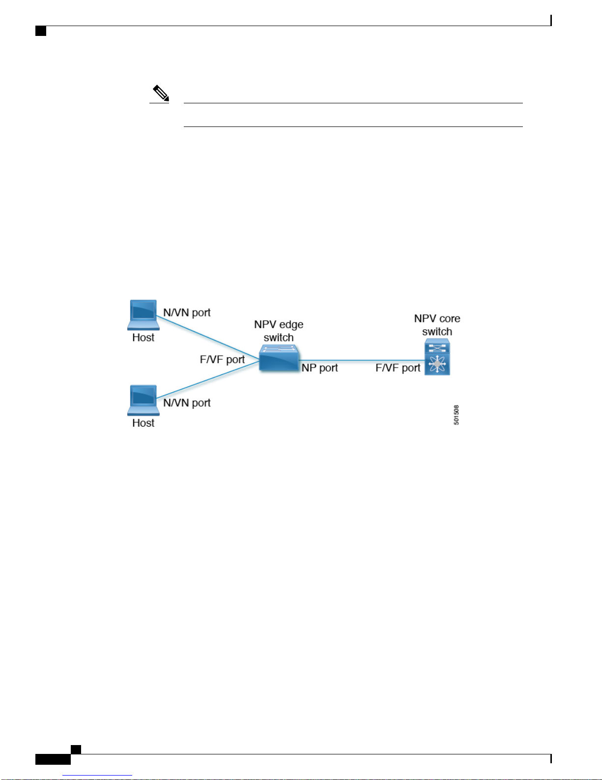
A switch is in NPV mode after enabling NPV. NPV mode applies to an entire switch. All end devices connected
to a switch that are in NPV mode must log in as an N port to use this feature (loop-attached devices are not
supported). All links from the edge switches (in NPV mode) to the NPV core switches are established as NP
ports (not E ports), which are used for typical inter-switch links. NPIV is used by the switches in NPV mode
to log in to multiple end devices that share a link to the NPV core switch.
The following figure shows an interface-level view of an FC NPV configuration.
Figure 1: FC NPV Interface Configuration
Configuring N Port Virtualization
DS-SFP-FC32G-SW operates at 16G speed.Note
FC NPV Benefits
FC NPV provides the following:
Increased number of hosts that connect to the fabric without adding domain IDs in the fabric
•
Connection of FC and FCoE hosts and targets to SAN fabrics using FC interfaces
•
Automatic traffic mapping
•
Static traffic mapping
•
FC NPV Mode
In FC NPV mode, the edge switch relays all traffic to the core switch and shares the domain ID of the core
switch.
FC NPV is enabled by installing and enabling feature-set fcoe-npv. You cannot configure FC NPV mode
on a per-interface basis. FC NPV mode applies to the entire switch.
Cisco Nexus 9000 Series NX-OS FC NPV Configuration Guide
2
Page 3

Configuring N Port Virtualization
Server Interfaces
In Cisco Nexus 9000 Series switches, server interfaces can be FC or vFC interfaces.
•
Server interfaces are F ports on the edge switch that connect to the servers. A server interface may
•
support multiple end devices by enabling the N port identifier virtualization (NPIV) feature. NPIV
provides a means to assign multiple FC IDs to a single N port, which allows the server to assign unique
FC IDs to different applications.
Server Interfaces
NP Uplinks
Note
FC server interfaces should be in trunk mode off. Trunk mode on is not supported.
•
vFC server interfaces should be in trunk mode on.
•
Server interfaces are automatically distributed among the NP uplinks to the core switch. All of the end
•
devices connected to a server interface are mapped to the same NP uplink.
8 G speed is not supported for server and target interfaces.
•
The default speed is 16 G.
•
In Cisco Nexus 9000 Series switches, NP uplink interfaces can be native Fibre Channel interfaces, virtual
•
fiber channel interfaces, SAN port channel interfaces, or virtual ethernet port-channel interfaces.
All interfaces from the edge switch to the core switch are configured as proxy N ports (NP ports).
•
An NP uplink is a connection from an NP port on the edge switch to an F port on the core switch. When
•
an NP uplink is established, the edge switch sends a fabric login message (FLOGI) to the core switch
then (if the FLOGI is successful) registers itself with the name server on the core switch. Subsequent
FLOGIs from end devices connected to this NP uplink are forwarded as-is to the core switch. Subsequent
flags from the same VSAN are forwarded as fdisc.
To use NPIV, enable the NPIV feature and reinitialize the server interfaces that will
support multiple devices.
Note
The features below must be enabled on the core switch:
•
If the FC uplink speed is 8 G, the fill pattern should be configured as IDLE on the core switch.
•
In the switch CLI configuration commands and output displays, NP uplinks are called
External Interfaces.
feature npiv
◦
feature fport-channel-trunk
◦
Cisco Nexus 9000 Series NX-OS FC NPV Configuration Guide
3
Page 4

SAN Port Channels
Configuring N Port Virtualization
Note
Note
For the FLOGI from NP uplink of Cisco Nexus 9000 Series switches to be successful on the core
•
Following is an example of configuring IDLE fill pattern on a Cisco MDS switch:
Switch(config)# int fc2/3
Switch(config)# switchport fill-pattern IDLE speed 8000
Switch(config)# sh run int fc2/3
interface fc2/3
switchport speed 8000
switchport mode NP
switchport fill-pattern IDLE speed 8000
no shutdown
switch, the core should be configured with the OUI of a Cisco Nexus 9000 Series switch. Configure
the OUI on the core only if the core has not registered the OUI by default.
The OUI is found and configured as follows:
N9K(config-if)# show wwn switch
Switch WWN is 20:00:2c:d0:2d:50:ea:64
N9K(config-if)#
On the core, we see the output below if the OUI (0x2cd02d) is already registered.
MDS9710(config-if)# sh wwn oui | i 2cd02d
0x2cd02d Cisco Default
MDS9710(config-if) #
If the OUI is not registered with the core, configure it manually.
MDS9710(config-if)# wwn oui 0x2cd02d
Beginning in Cisco NX-OS Release 7.3(3)N1(1), the OUI is configurable on a Cisco Nexus 6000
•
Series core switch.
SAN Port Channels
About SAN Port Channels
A SAN port channel is a logical interface that combines a set of FC interfaces connected to the same
•
fibre channel node and operates as one link.
SAN port channels support bandwidth utilization and availability.
•
SAN port channels on Cisco Nexus 9000 Series switches are mainly used to connect to MDS cores and
•
to provide optimal bandwidth utilization and transparent failover between the uplinks of a VSAN.
Cisco Nexus 9000 Series NX-OS FC NPV Configuration Guide
4
Page 5

Configuring N Port Virtualization
Configuring SAN Port Channels
SAN port channels are created with default values. You can change the default configuration just as any other
physical interface.
If the following requirements are not met, a SAN port channel error is detected:
Each switch on either side of a SAN port channel must be connected to the same number of interfaces.
•
Each interface must be connected to a corresponding interface on the other side.
•
Links in a SAN port channel cannot be changed after the port channel is configured. If you change the
•
links after the port channel is configured, be sure to reconnect the links to interfaces within the port
channel and reenable the links.
Configuring SAN Port Channels
Note
If all three conditions are not met, the faulty link is disabled. Enter the show interface command for that
interface to verify that the SAN port channel is functioning as required.
SAN Port Channel Guidelines and Limitations
The number of SAN port channels and virtual FC port channels, together, can be only 8 on the Cisco
•
Nexus 9000 Series switch.
The maximum number of FC interfaces that can be combined into a SAN port channel is limited to 16.
•
The default channel mode on Cisco Nexus 9000 Series switches for SAN port channels is active; this
•
cannot be changed.
Creating a SAN Port Channel
This section explains how to create a SAN port channel.
Procedure
Step 1
switch# configuration terminal
Enters the global configuration mode.
Step 2
switch(config)# interface san-port-channel channel-number
Creates the specified SAN port channel using the default mode (on). The SAN port channel number is in the
range of 1 to 256
The following example shows the SAN port channel creation:
switch(config)# interface san-port-channel 1
switch(config-if)#
Cisco Nexus 9000 Series NX-OS FC NPV Configuration Guide
5
Page 6

Interfaces in a SAN Port Channel
About SAN Port Channel Modes
A SAN port channel is configured with channel mode active by default. When active, the member ports initiate
port-channel-protocol negotiation with the peer port(s) regardless of the channel-group mode of the peer port.
If the peer port, while configured in a channel group, does not support the port-channel protocol, or responds
with a nonnegotiable status, the port channel will be disabled. The active port -channel mode allows automatic
recovery without explicitly enabling and disabling the port-channel-member ports at either end.
About Deleting SAN Port Channels
When you delete the SAN port channel, the corresponding channel membership is also deleted.
If you delete the SAN port channel for one port, then the individual ports within the deleted SAN port channel
retain the compatibility parameter settings (speed, mode, port VSAN, allowed VSAN, and port security). You
can explicitly change those settings as required.
Deleting SAN Port Channels
Configuring N Port Virtualization
This section explains how to delete a SAN port channel.
Procedure
Step 1
Step 2
switch# configuration terminal
Enters global configuration mode.
switch(config)#no interface san-port-channel channel-number
Deletes the specified port channel, its associated interface mappings, and the hardware associations for this
SAN port channel.
The following example demonstrates how to delete a SAN port channel:
switch(config)# no interface san-port-channel 1
The SAN port channel 1 is deleted and all its members are disabled. Please do the same operation on the
switch at the other end of the SAN port channel.
Interfaces in a SAN Port Channel
You can add or remove a physical Fibre Channel interface (or a range of interfaces) to an existing SAN port
channel. The compatible parameters on the configuration are mapped to the SAN port channel. Adding an
interface to a SAN port channel increases the channel size and bandwidth of the SAN port channel. Removing
an interface from a SAN port channel decreases the channel size and bandwidth of the SAN port channel.
Virtual Fibre Channel interfaces cannot be added to SAN port channels.Note
Cisco Nexus 9000 Series NX-OS FC NPV Configuration Guide
6
Page 7

Configuring N Port Virtualization
Adding an Interface to a SAN Port Channel
This section explains how to add an interface to a SAN port channel.
Procedure
Interfaces in a SAN Port Channel
Step 1
switch#configuration terminal
Enters global configuration mode.
Step 2
switch(config)# interface type slot /port
Enters configuration mode for the specified interface.
Step 3
switch(config-if)#channel-group channel-number
Adds the Fibre Channel interface to the specified channel group. If the channel group does not exist, it is
created. The port is shut down.
The following example adds an interface to a SAN port channel:
switch(config)# interface fc2/3
switch(config-if)# channel-group 15
fc2/3 is added to san-port-channel 15 and is disabled. Please do the same operation on the switch at the other
end of the san-port-channel, then do “no shutdown” at both ends to bring them up
Forcing an Interface Addition
You can force the port configuration to be overwritten by the SAN port channel. In this case, the interface is
added to a SAN port channel.
When SAN port channels are created from within an interface, the force option cannot be used.Note
This section explains how to force the addition of a port to a SAN port channel.
Procedure
Step 1
switch# configuration terminal
Enters global configuration mode.
Step 2
switch(config)#interface type slot / port
Enters configuration mode for the specified interface.
Step 3
switch(config-if)# channel-group channel-number force
Forces the addition of the interface into the specified channel group. The E port is shut down.
The following example adds an interface to a SAN port channel:
switch(config)# interface fc2/3
switch(config-if)# channel-group 15 force
Cisco Nexus 9000 Series NX-OS FC NPV Configuration Guide
7
Page 8

Verifying SAN Port Channel Configurations
fc2/3 added to san-port-channel 15 and disabled. Please do the same operation on the switch at the other end
of the san-port-channel, then perform a no shutdown at both ends to bring them up
About Interface Deletion from a SAN Port Channel
When a physical interface is deleted from the SAN port channel, the channel membership is automatically
updated. If the deleted interface is the last operational interface, then the port channel status is changed to a
down state. Deleting an interface from a SAN port channel decreases the channel size and bandwidth of the
SAN port channel.
Deleting an Interface from a SAN Port Channel
This section explains how to delete a physical interface (or a range of physical interfaces) from a SAN port
channel.
Procedure
Configuring N Port Virtualization
Step 1
Step 2
switch(config)# interface type slot /port
Enters configuration mode for the specified interface.
switch(config)#no channel-group channel-number
Deletes the physical Fibre Channel interface from the specified channel group.
The following example deletes an interface from a SAN port channel:
switch(config)# interface fc2/3
witch(config-if)# no channel-group 15
fc2/1 is removed from the SAN port-channel 2 and disabled.
Please do the same operation on the switch at the other end of the san-port-channel
Verifying SAN Port Channel Configurations
You can view specific information about existing SAN port channels at any time from EXEC mode. The
following show commands provide further details on existing SAN port channels.
The show san-port-channel summary command displays a summary of SAN port channels within the switch.
A one-line summary of each SAN port channel provides the administrative state, the operational state, the
number of attached and active interfaces (up), and the first operational port (FOP), which is the primary
operational interface selected in the SAN port channel to carry control-plane traffic (no load-balancing). The
FOP is the first port that comes up in a SAN port channel and can change if the port goes down. The FOP is
also identified by an asterisk ( *).
To display VSAN configuration information, perform one of the following tasks:
Cisco Nexus 9000 Series NX-OS FC NPV Configuration Guide
8
Page 9

Configuring N Port Virtualization
Procedure
FLOGI Operation
Step 1
Step 2
Step 3
switch# show san-port-channel summary | database | consistency [ details ] | usage |
compatibility-parameters
Displays SAN port channel information.
switch# show san-port-channel database interface san-port-channel channel-number
Displays information for the specified SAN port channel.
switch# show interface fc slot / port
Displays VSAN configuration information for the specified Fibre Channel interface.
The following example shows how to display a summary of SAN port channel information:
switch# show san-port-channel summary
-----------------------------------------------------------------------------Interface Total Ports Oper Ports First Oper Portsan-port-channel 7 2 0 –
san-port-channel 8 2 0 –
san-port-channel 9 2 2
The following example shows how to display SAN port channel consistency:
switch# show san-port-channel consistency
Database is consistent
The following example shows how to display details of the used and unused port channel numbers:
switch# show san-port-channel usage
Totally 3 port-channel numbers used===================================Used : 77 - 79Unused:
1 - 76, 80 - 256
FLOGI Operation
When an NP port becomes operational, the switch first logs itself in to the core switch by sending a FLOGI
request (using the port WWN of the NP port).
After completing the FLOGI request, the switch registers itself with the fabric name server on the core switch
(using the symbolic port name of the NP port and the IP address of the edge switch).
The following table identifies port and node names in the edge switch used in FC NPV mode.
Table 1: Edge Switch FLOGI Parameters
symbolic port name
Derived FromParameter
The fWWN of the NP port on the edge switch.pWWN
The VSAN-based sWWN of the edge switch.nWWN
The edge switch name and NP port interface string.
Note
If no switch name is available, the output
will read "switch." For example, switch: fc
1/5.
Cisco Nexus 9000 Series NX-OS FC NPV Configuration Guide
9
Page 10

NPV Traffic Management
NPV Traffic Management
Automatic Uplink Selection
NPV supports automatic selection of NP uplinks. When a server interface is brought up, the NP uplink interface
with the minimum load is selected from the available NP uplinks in the same VSAN as the server interface.
When a new NP uplink interface becomes operational, the existing load is not redistributed automatically to
include the newly available uplink. Server interfaces that become operational after the NP uplink can select
the new NP uplink.
Configuring N Port Virtualization
Derived FromParameter
The IP address of the edge switch.IP address
The edge switch name.symbolic node name
Traffic Maps
In Release 7.0(3)I7(2) and later software releases, FC NPV supports traffic maps. A traffic map allows you
to specify the NP uplinks that a server interface can use to connect to the core switches.
Note
When an FC NPV traffic map is configured for a server interface, the server interface must select only
from the NP uplinks in its traffic map. If none of the specified NP uplinks are operational, the server
remains in a non-operational state.
The FC NPV traffic map feature provides the following benefits:
Facilitates traffic engineering by allowing configuration of a fixed set of NP uplinks for a specific server
•
interface (or range of server interfaces).
Ensures correct operation of the persistent FC ID feature; this is because a server interface will always
•
connect to the same NP uplink (or one of a specified set of NP uplinks) after an interface reinitialization
or switch reboot.
Enables an external interface to be an individual link or SAN port channel.
•
Disruptive Auto Load Balancing of Server Logins across NP Links
In Release 7.0(3)I7(2) and later software releases, FC NPV supports disruptive load balancing. When disruptive
load balancing is enabled, FC NPV redistributes the server interfaces across all available NP uplinks when a
new NP uplink becomes operational. To move a server interface from one NP uplink to another NP uplink,
FC NPV forces reinitialization of the server interface so that the server performs a new login to the core switch.
Cisco Nexus 9000 Series NX-OS FC NPV Configuration Guide
10
Page 11

Configuring N Port Virtualization
Only server interfaces that are moved to a different uplink are reinitialized. A system message is generated
for each server interface that is moved.
FC NPV Traffic Management Guidelines
Note
Redistributing a server interface causes traffic disruption to the attached end devices. adding a member
to the existing port-channel does not trigger disruptive auto load-balance
Adding a member to the existing port channel does not trigger disruptive auto load balance.Note
To avoid disruption of server traffic, you should enable this feature only after adding a new NP uplink, and
then disable it again after the server interfaces have been redistributed.
If disruptive load balancing is not enabled, you can manually reinitialize some or all of the server interfaces
to distribute server traffic to new NP uplink interfaces.
FC NPV Traffic Management Guidelines
When deploying FC NPV traffic management, follow these guidelines:
Use FC NPV traffic management only when automatic traffic engineering does not meet your network
•
requirements.
You do not need to configure traffic maps for all server interfaces. By default, FC NPV will use automatic
•
traffic management.
Server interfaces configured to use a set of NP uplink interfaces cannot use any other available NP uplink
•
interfaces, even if none of the configured interfaces are available.
When disruptive load balancing is enabled, a server interface may be moved from one NP uplink to
•
another NP uplink. Moving between NP uplink interfaces requires FC NPV to relogin to the core switch,
causing traffic disruption.
To link a set of servers to a specific core switch, associate the server interfaces with a set of NP uplink
•
interfaces that all connect to that core switch.
Configure Persistent FC IDs on the core switch and use the Traffic Map feature to direct server interface
•
traffic onto NP uplinks that all connect to the associated core switch.
FC NPV Guidelines and Limitations
When configuring FC NPV, note the following guidelines and limitations:
Fibre Channel N-port Virtualization (NPV) can co-exist with VXLAN on different fabric uplinks but
•
on same or different front panel ports on the Cisco Nexus 93180YC-FX switches. VXLAN can only
exist on the Ethernet front panel ports but not on the FC front panel ports.
In-order data delivery is not required in FC NPV mode because the exchange between two end devices
•
always takes the same uplink from the edge switch to the core. Upstream of the edge switch, core switches
will enforce in-order delivery if configured.
Cisco Nexus 9000 Series NX-OS FC NPV Configuration Guide
11
Page 12

FC NPV Guidelines and Limitations
You can configure zoning for end devices that are connected to edge switches using all the available
•
member types on the core switch. However, the preferred way of zoning servers connected to any switch
in NPV mode is via PWWN, device-alias and fcalias. You must place multiple servers in the same zone
only when using smart zoning. For more information about smart zoning on Cisco MDS switches, refer
the chapter Configuring and Managing Zones in Cisco MDS 9000 Series Fabric Configuration Guide
.
Port tracking is not supported in FC NPV mode.
•
Port security is supported on the core switch for devices logged in through the FC NPV switch. Port
•
security is enabled on the core switch on a per-interface basis. To enable port security on the core switch
for devices that log in through an FC NPV switch, you must adhere to the following requirements:
◦
◦
Edge switches can connect to multiple core switches. In other words, different NP ports can be connected
•
to different core switches.
Configuring N Port Virtualization
The internal FLOGI must be in the port security database; in this way, the port on the core switch
will allow communications and links.
All the end device pWWNs must also be in the port security database.
If a server interface goes down and then returns to service, the interface is not guaranteed to be assigned
•
to the same NP uplink.
The server interface is only operational when its assigned NP uplink is operational.
•
Both servers and targets can be connected to the switch when in FC NPV mode.
•
Fibre Channel switching is not performed in the edge switch; all traffic is switched in the core switch.
•
FC NPV supports NPIV-capable servers. This capability is called nested NPIV.
•
Connecting two Cisco FC NPV switches together is not supported.
•
Only F and NP ports are supported in FC NPV mode.
•
The BB_SCN is not supported.
•
The auto-speed is not supported.
•
The default port speed is 16000.
•
8G speed is not supported for server and target interfaces.
•
IDLE is the fill pattern used for 8G NP links. All NPIV core switches need to have fill-pattern IDLE
•
configured. IDLE is configured on Cisco Nexus switches and Cisco MDS switches using switchport
fill-pattern command.
The speed must be configured manually for each port (based on the speed of peer).
•
64 B2B credits are assigned to each FC interface; this is not configurable.
•
When a san-port channel is created, it is created in channel mode active by default; channel mode on
•
is not supported for NPV switch.
FC NPV (upto 16G) is supported on N9K-C93180YC-FX, beginning with Cisco NX-OS Release
•
7.0(3)I7(2).
Cisco Nexus 9000 Series NX-OS FC NPV Configuration Guide
12
Page 13

Configuring N Port Virtualization
Licensing Requirements for FC NPV
The following table shows the licensing requirements for FC NPV.
Licensing Requirements for FC NPV
License RequirementProduct IDProduct
Cisco NX-OS
N93-16Y-SSK9
•
N93-48Y-SSK9
•
Configuring NPV
Installing the Fibre Channel Port License
This section explains how to install the licensing for FC NPV.
Before You Begin
Enabling the port license requires fibre channel (FC) ports.
Procedure
FC NPV requires the following:
FC NPV (up to 16 ports) and FCoE NPV
•
FC NPV (up to 48 ports) and FCoE NPV
•
Note
For a complete explanation of the Cisco
NX-OS licensing scheme and how to obtain
and apply licensees, see the Cisco NX-OS
Licensing Guide.
Install the license key file:
Example:
switch# install license bootflash:license_file.lic
Installing license ..done
Enabling FC NPV
FC NPV is enabled when feature-set fcoe-npv is installed and enabled.
To enable fcoe-npv, perform this task:
This enables both FC and FCoE NPV mode.Note
Cisco Nexus 9000 Series NX-OS FC NPV Configuration Guide
13
Page 14

Converting Ethernet Ports to Fibre Channel
Procedure
Configuring N Port Virtualization
PurposeCommand or Action
Step 1
Step 2
Step 3
Converting Ethernet Ports to Fibre Channel
This section explains how to convert Ethernet ports to fibre channel ports.
Before You Begin
This task requires installing and enabling the port license. For more information, see Installing the Fibre
Channel Port License, on page 13.
Procedure
Step 1
Step 2
Perform TCAM carving.
Example:
Switch(config)# hardware access-list tcam region ing-racl 1536
Switch(config)# hardware access-list tcam region ing-redirect 256
Confirm that feature-set fcoe-npv is installed and enabled.
Enters configuration mode.switch# configure terminal
Installs the FC and FCoE NPV feature set.switch(config)# install feature-set fcoe-npv
Enables FC and FCoE NPV.switch(config-npv)# feature-set fcoe-npv
Example:
Switch(config)# install feature-set fcoe-npv
Switch(config)# feature-set fcoe-npv
Step 3
Convert the port(s) to FC.
Example:
Switch(config)# slot 1
Switch(config)# port 1-4,45-48 type fc
Port type is changed. ACTION REQUIRED: Please save configurations and reload the switch
After the conversion, save the configuration and reload the switch.
Note
Ports can be converted only in groups (sequential or random) of 5 (multiples of
4).
Cisco Nexus 9000 Series NX-OS FC NPV Configuration Guide
14
Page 15

Configuring N Port Virtualization
Enabling the Fibre Channel Port License
This section explains how to enable the licensing for FC NPV.
Before You Begin
Enabling the port license requires fibre channel (FC) ports.
Procedure
Enable the port license.
Example:
Switch(config)# int fc1/1
Switch(config)# port-license acquire
Enabling the Fibre Channel Port License
Configuring FC NPV Interfaces
After you enable FC NPV, you should configure the NP uplink interfaces and the server interfaces.
Configuring FC NPV Interfaces
To configure an NP uplink interface, perform this task:
Procedure
Step 1
Step 2
Step 3
Step 4
Step 5
switch(config)# interface { fc slot/port |
san-port-channel <number> }
switch(config-if)# switchport speed speed
PurposeCommand or Action
Enters global configuration mode.switch# configure terminal
Selects an interface (Fibre Channel or SAN port
channel) that will be connected to the core FC
NPV switch.
Sets the speed, which can be 4 G, 8G, or 16 G
Note
Configures the interface as an NP port.switch(config-if)# switchport mode NP
Brings up the interface.switch(config-if)# no shutdown
8 G speed is not supported for server and
target interfaces.
Configuring a Server Interface
To configure a server interface, perform this task:
Cisco Nexus 9000 Series NX-OS FC NPV Configuration Guide
15
Page 16

Configuring FC NPV Interfaces
Procedure
Configuring N Port Virtualization
PurposeCommand or Action
Step 1
Step 2
Step 3
Step 4
switch(config)# interface fc
slot/port
speed speed
mode F
Enters global configuration mode.switch# configure terminal
Creates an interface that connects the server to the NPV
switch.
Sets the speed, which can be 4 G, 8G, or 16 Gswitch(config-if)# switchport
Note
8 G speed is not supported for server and target
interfaces.
Following is an example of configuring IDLE fill
pattern on a Cisco MDS switch:
Switch(config)# int fc2/3
Switch(config)# switchport fill-pattern IDLE speed
8000
Switch(config)# sh run int fc2/3
interface fc2/3
switchport speed 8000
switchport mode NP
switchport fill-pattern IDLE speed 8000
no shutdown
Configures the interface as an F port.switch(config-if)# switchport
Step 5
Configuring QoS
Configuring Default QoS
There are four types of FCoE default policies: network QoS, output queuing, input queuing, and QoS. You
can enable the FCoE default policies by enabling the FCoE NPV feature using the feature-set fcoe-npv
command. The default QoS ingress policy, default-fcoe-in-policy, is implicitly attached to all FC and
SAN-port-channel interfaces to enable FC to FCoE traffic; this can be verified by using show interface {fc
slot/port | san-port-channel <no>} all command. The default QoS policy uses CoS3 and Q1 for all FC and
FCoE traffic.
Configuring User-Defined QoS
To use a different queue or CoS value for FCoE traffic, create user-defined policies. The user-defined QoS
ingress policy has to be created and attached explicitly to both FC and FCoE interfaces to enable traffic to
use a different queue or CoS. User-defined QoS policies must be created and activated for system-wide QoS.
Brings up the interface.switch(config-if)# no shutdown
Cisco Nexus 9000 Series NX-OS FC NPV Configuration Guide
16
Page 17

Configuring N Port Virtualization
The following example demonstrates how to configure and activate user-defined QoS policies that use CoS3
and Q2 for all FC and FCoE traffic.
•
•
Configuring FC NPV Interfaces
Creating a user-defined network QOS policy:
switch(config)# policy-map type network-qos fcoe_nq
switch(config-pmap-nqos)# class type network-qos c-nq1
switch(config-pmap-nqos-c)# mtu 1500
switch(config-pmap-nqos-c)# class type network-qos c-nq2
switch(config-pmap-nqos-c)# mtu 9216
switch(config-pmap-nqos-c)# pause pfc-cos 3
switch(config-pmap-nqos-c)# class type network-qos c-nq3
switch(config-pmap-nqos-c)# mtu 1500
switch(config-pmap-nqos-c)# class type network-qos c-nq-default
switch(config-pmap-nqos-c)# mtu 1500
switch(config-pmap-nqos-c)# exit
switch(config-pmap-nqos)# exit
switch(config)#
Creating a user-defined input queuing policy:
switch(config)# policy-map type queuing fcoe-in-policy
switch(config-pmap-que)# class type queuing c-in-q2
switch(config-pmap-c-que)# bandwidth percent 50
switch(config-pmap-c-que)# class type queuing c-in-q-default
switch(config-pmap-c-que)# bandwidth percent 50
switch(config-pmap-c-que)# exit
switch(config-pmap-que)# exit
switch(config)
Creating a user-defined output queuing policy:
•
switch(config)# policy-map type queuing fcoe-out-policy
switch(config-pmap-que)# class type queuing c-out-q3
switch(config-pmap-c-que)# priority level 1
switch(config-pmap-c-que)# class type queuing c-out-q-default
switch(config-pmap-c-que)# bandwidth remaining percent 50
switch(config-pmap-c-que)# class type queuing c-out-q1
switch(config-pmap-c-que)# bandwidth remaining percent 0
switch(config-pmap-c-que)# class type queuing c-out-q2
switch(config-pmap-c-que)# bandwidth remaining percent 50
switch(config-pmap-c-que)# exit
switch(config-pmap-que)# exit
switch(config)#
Creating a user-defined QoS input policy:
•
switch(config)# class-map type qos match-any fcoe
switch(config-cmap-qos)# match protocol fcoe
switch(config-cmap-qos)# match cos 3
switch(config-cmap-qos)# exit
switch(config)#
switch(config)# policy-map type qos fcoe_qos_policy
switch(config-pmap-qos)# class fcoe
switch(config-pmap-c-qos)# set cos 3
switch(config-pmap-c-qos)# set qos-group 2
switch(config-pmap-c-qos)# exit
switch(config-pmap-qos)# exit
switch(config)#
Activating a user-defined system QoS policy:
•
switch(config)# system qos
switch(config-sys-qos)# service-policy type queuing input fcoe-in-policy
switch(config-sys-qos)# service-policy type queuing output fcoe-out-policy
switch(config-sys-qos)# service-policy type network-qos fcoe_nq
switch(config-sys-qos)# exit
switch(config)#
Cisco Nexus 9000 Series NX-OS FC NPV Configuration Guide
17
Page 18

Configuring NPV Traffic Management
Applying a QoS input policy to an FC or FCoE interface:
•
switch# conf
switch(config)# interface fc <slot>/<port> | ethernet <slot>/<port> | san-port-channel
<no> | port-channel <no>
switch(config-if)# service-policy type qos input fcoe_qos_policy
Removing a QoS input policy from an FC or FCoE interface:
•
switch# conf
switch(config)# interface fc <slot>/<port> | ethernet <slot>/<port> | san-port-channel
<no> | port-channel <no>
switch(config-if)# no service-policy type qos input fcoe_qos_policy
Verifying a QoS input policy applied to an FC or FCoE interface:
•
switch# show running-config interface fc <slot>/<port> | interface <slot>/<port> |
san-port-channel <no> | port-channel <no> all
Configuring N Port Virtualization
Note
When a user-defined QoS policy is used, the same QoS input policy must be applied to all FC and
•
FCoE interfaces in the switch.
Do not configure match protocol fcoe under more than one QoS class map, as FCoE traffic is
•
supported only on a single CoS.
Configuring NPV Traffic Management
Configuring NPV Traffic Maps
An NPV traffic map associates one or more NP uplink interfaces with a server interface. The switch associates
the server interface with one of these NP uplinks.
Note
to map the server interface to a different uplink, the server interface must be shut down before configuring
the traffic map.
To configure a traffic map, perform this task:
Procedure
Step 1
Step 2
switch(config)# npv traffic-map
server-interface {fc slot/port | vfc vfc-id}
external-interface { fc slot/port |
san-port-channel <number> | vfc vfc-id |
vfc-port-channel vfc-port-channel-id }
Cisco Nexus 9000 Series NX-OS FC NPV Configuration Guide
18
PurposeCommand or Action
Enters global configuration mode.switch# configure terminal
Configures a mapping between a server interface
(or range of server interfaces) and an NP uplink
interface (or range of NP uplink interfaces).
Page 19

Configuring N Port Virtualization
PurposeCommand or Action
Note
Verifying FC NPV
To map the server interface to a
different uplink, the server interface
must be shut down before configuring
the traffic map.
Step 3
switch(config)# no npv traffic-map
server-interface {fc slot/port | vfc vfc-id}
external-interface { fc slot/port |
san-port-channel <number> | vfc vfc-id |
vfc-port-channel vfc-port-channel-id }
Enabling Disruptive Load Balancing
If you configure additional NP uplinks, you can enable the disruptive load-balancing feature to distribute the
server traffic load evenly among all the NP uplinks.
To enable disruptive load balancing, perform this task:
Procedure
Step 1
Step 2
Step 3
switch(config)# npv auto-load-balance
disruptive
switch (config)# no npv auto-load-balance
disruptive
Removes the mapping between the specified
server interfaces and NP uplink interfaces.
PurposeCommand or Action
Enters configuration mode on the NPV.switch# configure terminal
Enables disruptive load balancing on the
switch.
Disables disruptive load balancing on the
switch.
Verifying FC NPV
To display information about FC NPV, perform the following task:
Procedure
Step 1
PurposeCommand or Action
switch# show feature-set | i fcoe
Example:
switch# show feature-set | i fcoe
fcoe-npv 8 enabled
Cisco Nexus 9000 Series NX-OS FC NPV Configuration Guide
19
Page 20

Verifying FC NPV Examples
Configuring N Port Virtualization
PurposeCommand or Action
Step 2
switch# show npv flogi-table [all]
Verifying FC NPV Examples
To display a list of devices on a server interface and their assigned NP uplinks, enter the show npv flogi-table
command on the Cisco Nexus 9000 Series switch:
switch# show npv flogi-table
-------------------------------------------------------------------------------SERVER EXTERNAL
INTERFACE VSAN FCID PORT NAME NODE NAME INTERFACE
--------------------------------------------------------------------------------vfc3/1 1 0xee0008 10:00:00:00:c9:60:e4:9a 20:00:00:00:c9:60:e4:9a fc2/1
vfc3/1 1 0xee0009 20:00:00:00:0a:00:00:01 20:00:00:00:c9:60:e4:9a fc2/2
vfc3/1 1 0xee000a 20:00:00:00:0a:00:00:02 20:00:00:00:c9:60:e4:9a fc2/3
vfc3/1 1 0xee000b 33:33:33:33:33:33:33:33 20:00:00:00:c9:60:e4:9a fc2/4
Total number of flogi = 4
For each server interface, the External Interface value displays the assigned NP uplink.Note
To display the status of the server interfaces and the NP uplink interfaces, enter the show npv status command:
switch# show npv status
Displays the FC NPV
configuration.
npiv is enabled
disruptive load balancing is disabled
External Interfaces:
====================
Interface: fc1/47, State: Down
Interface: san-port-channel 200, State: Trunking
VSAN: 1, State: Up
VSAN: 200, State: Up
VSAN: 201, State: Up
VSAN: 202, State: Up, FCID: 0xea0020
VSAN: 100, State: Up
VSAN: 55, State: Up
Interface: vfc-po149, State: Trunking
VSAN: 201, State: Up
VSAN: 202, State: Up, FCID: 0xea0260
VSAN: 100, State: Up
Interface: vfc-po4090, State: Trunking
VSAN: 201, State: Up
VSAN: 202, State: Up, FCID: 0xea0220
VSAN: 100, State: Up
Interface: vfc1/9, State: Trunking
VSAN: 201, State: Up
VSAN: 202, State: Up, FCID: 0xea0240
VSAN: 100, State: Up
Number of External Interfaces: 5
Server Interfaces:
==================
Interface: fc1/38, VSAN: 100, State: Up
Cisco Nexus 9000 Series NX-OS FC NPV Configuration Guide
20
Page 21

Configuring N Port Virtualization
Interface: fc1/39, VSAN: 202, State: Up
Interface: fc1/40, VSAN: 4094, State: Down
Interface: vfc100, VSAN: 4094, State: Down
Interface: vfc151, VSAN: 4094, State: Down
Interface: vfc1/14, VSAN: 100, State: Up
Number of Server Interfaces: 6
Verifying FC NPV Examples
Note
To view fcns database entries for FC NPV edge switches, you must enter the show fcns database command
on the core switch.
To view all the FC NPV edge switches, enter the show fcns database command on the core switch:
core-switch# show fcns database
For additional details (such as IP addresses, switch names, interface names) about the FC NPV edge switches
that you see in the show fcns database output, enter the show fcns database detail command on the core
switch:
core-switch# show fcns database detail
======================================================================
-----------------------VSAN:100 FCID:0xe101c0
-----------------------port-wwn (vendor) :50:0a:09:82:ad:0d:86:37 (NetApp)
node-wwn :50:0a:09:80:8d:0d:86:37
class :3
node-ip-addr :0.0.0.0
ipa :00 00 00 00 1e 22 a0 00
fc4-types:fc4_features :scsi-fcp:target
symbolic-port-name :NetApp FC Target Adapter (8112) lab-D-netapp01:3b
symbolic-node-name :NetApp FAS3240 (lab-D-netapp01)
port-type :N
port-ip-addr :0.0.0.0
fabric-port-wwn :21:61:00:2a:6a:5b:da:00
hard-addr :0x000000
permanent-port-wwn (vendor) :50:0a:09:82:ad:0d:86:37 (NetApp)
connected interface :vfc6/33
switch name (IP address) :MDS9706 (10.105.188.173)
-----------------------VSAN:100 FCID:0xe101ef
-----------------------port-wwn (vendor) :50:06:01:6b:08:60:7c:71 (Clariion)
node-wwn :50:06:01:60:88:60:7c:71
class :3
node-ip-addr :0.0.0.0
ipa :ff ff ff ff ff ff ff ff
fc4-types:fc4_features :scsi-fcp:both
symbolic-port-name :CLARiiON::::SPB23::FC::::::
symbolic-node-name :CLARiiON::::SPB::FC::::::
port-type :N
port-ip-addr :0.0.0.0
fabric-port-wwn :20:19:00:2a:6a:5b:da:00
hard-addr :0x000000
permanent-port-wwn (vendor) :50:06:01:6b:08:60:7c:71 (Clariion)
connected interface :fc1/25
switch name (IP address) :MDS9706 (10.105.188.173)
core-switch# show interface fc 1/1
fc1/1 is trunking
Hardware is Fibre Channel, SFP is short wave laser w/o OFC (SN)
Port WWN is 20:01:2c:d0:2d:50:d2:a0
Admin port mode is NP, trunk mode is on
snmp link state traps are enabled
Port mode is TNP
Port vsan is 201
Speed is 16 Gbps
Transmit B2B Credit is 500
Receive B2B Credit is 64
Receive data field Size is 2112
Cisco Nexus 9000 Series NX-OS FC NPV Configuration Guide
21
Page 22

Verifying FC NPV Traffic Management
Beacon is turned off
Belongs to san-port-channel 200
Trunk vsans (admin allowed and active) (1,55,100,200-202,204)
Trunk vsans (up) (100,202)
Trunk vsans (isolated) (204)
Trunk vsans (initializing) (1,55,200-201)
5 minutes input rate 0 bits/sec,0 bytes/sec, 0 frames/sec
5 minutes output rate 0 bits/sec,0 bytes/sec, 0 frames/sec
406 frames input,40164 bytes
0 discards,0 errors
0 invalid CRC/FCS,0 unknown class
0 too long,0 too short
192 frames output,14364 bytes
0 discards,0 errors
1 input OLS,1 LRR,5 NOS,0 loop inits
3 output OLS,1 LRR, 4 NOS, 0 loop inits
500 transmit B2B credit remaining
0 low priority transmit B2B credit remaining
Last clearing of "show interface" counters :never
Verifying FC NPV Traffic Management
To display the FC NPV traffic map, enter the show npv traffic-map command.
switch# show npv traffic-map
NPV Traffic Map Information:
---------------------------------------Server-If External-If(s)
---------------------------------------fc1/3 fc1/10,fc1/11
fc1/5 fc1/1,fc1/2
----------------------------------------
To display the FC NPV internal traffic details, enter the show npv internal info traffic-map command.
Configuring N Port Virtualization
Verifying Disruptive Load Balancing
To display the disruptive load-balancing status, enter the show npv status command:
switch# show npv status
npiv is enabled
disruptive load balancing is enabled
External Interfaces:
====================
Interface: fc2/1, VSAN: 2, FCID: 0x1c0000, State: Up
...
FC NPV Core Switch and FC NPV Edge Switch Configuration
Example
Before You Begin
This section demonstrates how to configure FC NPV core and edge switches.
Procedure
Step 1
Procure and install the FC_PORT_ACTIVATION_PKG and FCOE_NPV_PKG licenses.
Cisco Nexus 9000 Series NX-OS FC NPV Configuration Guide
22
Page 23

Configuring N Port Virtualization
FC NPV Core Switch and FC NPV Edge Switch Configuration Example
Step 2
Step 3
Step 4
Step 5
Note
The license file is in the .lic format and has to be copied to the switch and installed using the following
command:
Check out the license:
Switch# install license bootflash:Switch_port_lic_48.lic
Switch(config)# install feature-set fcoe-npv
Switch(config-vdc)# feature-set fcoe-npv
Configure the needed features on the NPV:
Switch(config)# feature telnet
Switch(config)# feature lacp
Switch(config)# feature lldp
Convert the FC port:
Switch(config)# slot 1
Switch(config-slot)# port 13-36 type fc
Port type is changed. ACTION REQUIRED: Please save configurations and reload the switch
Configure service policies:
Switch(config)# system qos
Switch(config-sys-qos)# service-policy type network-qos default-fcoe-8q-nq-policy
Switch(config-sys-qos)# service-policy type queuing output default-fcoe-8q-out-policy
Step 6
Step 7
Step 8
Step 9
Configure TCAM carving:
Switch(config-vrf)# hardware access-list tcam region ing-racl 1536
Warning: Please save config and reload the system for the configuration to take effect
Switch(config)# hardware access-list tcam region ing-redirect 256
Warning: Please save config and reload the system for the configuration to take effect
Copy the running configuration to startup:
Switch(config)# copy running-config startup-config
[########################################] 100%
(Mandatory) Reload the switch so that the port conversion is applied and TCAMS are carved properly:
Switch(config)# reload
This command will reboot the system. (y/n)? [n] y
2017 Sep 14 10:12:19 Switch %PLATFORM-2-PFM_SYSTEM_RESET: Manual system restart from Command
Line Interface
Configure VLAN-VSAN mappings:
Switch(config)# vlan 1,20,30,40,1000,1002,1010
Switch(config-vlan)# vlan 20
Switch(config-vlan)# fcoe vsan 200
Switch(config-vlan)# vlan 30
Switch(config-vlan)# fcoe vsan 200
Switch(config-vlan)# fcoe vsan 300
Switch(config-vlan)# vlan 40
Switch(config-vlan)# fcoe vsan 300
Cisco Nexus 9000 Series NX-OS FC NPV Configuration Guide
23
Page 24

FC NPV Core Switch and FC NPV Edge Switch Configuration Example
Switch(config)# vsan database
Switch(config-vsan-db)# vsan 40
Switch(config-vsan-db)# vsan 200
Switch(config-vsan-db)# vsan 300
Step 10
Step 11
Configure the port license:
Switch(config)# interface fc1/6
Switch(config-if)# port-license acquire
Configure the FC NP interface-facing core (this same configuration must be applied on the core switch with
switchport mode F or auto for the FC interface):
Switch(config-if)# interface fc1/6
Switch(config-if)# port-license acquire (this checks out the port license for FC ports)
Switch(config-if)# switchport trunk mode on
Switch(config-if)# switchport speed 16000
Switch(config-if)# switchport mode NP
Switch(config-if)# no shutdown
Configuring N Port Virtualization
Step 12
Step 13
Configure the virtual FC NP interface-facing core (this same configuration must be applied on the core switch
with switchport mode F or auto for the virtual FC interface):
a) Configure the physical Ethernet interface:
Switch(config-if)# interface Ethernet1/7
Switch(config-if)# switchport
Switch(config-if)# switchport mode trunk
Switch(config-if)# service-policy type qos input default-fcoe-in-policy
Switch(config-if)# mtu 9216
Switch(config-if)# no shutdown
b) Configure the virtual FC interface:
Switch(config-if)# interface vfc17
Switch(config-if)# bind interface ethernet1/7
Switch(config-if)# switchport mode NP
Switch(config-if)# no shutdown
Configure the SAN port channel interface-facing core (This same configuration must be applied on the core
switch with switchport mode F or auto for the port-channel interface. The SAN port-channel number can
be different.):
a) Configure the SAN port channel:
Switch(config)# interface san-port-channel 250
Switch(config-if)# channel mode active
Switch(config-if)# switchport mode NP
Switch(config-if)# switchport trunk mode on
b) Add a member to the SAN port channel:
Switch(config-if)# interface fc1/13
Switch(config-if)# port-license acquire (this checks out the port license for FC ports)
Switch(config-if)# switchport trunk mode on
Switch(config-if)# channel-group 250 force
fc1/13 added to port-channel 250 and disabled
Cisco Nexus 9000 Series NX-OS FC NPV Configuration Guide
24
Page 25

Configuring N Port Virtualization
Please do the same operation on the switch at the other end of the port-channel,
then do "no shutdown" at both ends to bring it up
Switch(config-if)# no shutdown
FC NPV Core Switch and FC NPV Edge Switch Configuration Example
Step 14
Step 15
Configure the vFC port channel interface-facing core (This same configuration must be applied on the core
switch with switchport mode F or auto for the virtual FC port-channel interface. The vFC port-channel
number can be different):
a) Configure the Ethernet port-channel interface:
Switch(config)# interface port-channel500
Switch(config-if)# switchport
Switch(config-if)# switchport mode trunk
Switch(config-if)# mtu 9216
Switch(config-if)# service-policy type qos input default-fcoe-in-policy
b) Add a member to the Ethernet port channel:
Switch(config-if)# interface Ethernet1/4
Switch(config-if)# channel-group 500 mode active
Switch(config-if)# no shutdown
c) Create a virtual FC port-channel interface:
Switch(config)# interface vfc-po500 (this creates a vFC)
Switch(config-if)# bind interface port-channel500
Switch(config-if)# switchport mode NP
Switch(config-if)# switchport trunk mode on)
Switch(config-if)# service-policy type qos input default-fcoe-in-policy
Switch(config-if)# no shutdown
Configure the FCoE server interface-facing server:
a) Configure the physical Ethernet interfaces:
Switch(config-if)# interface Ethernet1/6
Switch(config-if)# switchport
Switch(config-if)# switchport mode trunk
Switch(config-if)# service-policy type qos input default-fcoe-in-policy
Switch(config-if)# mtu 9216
Switch(config-if)# no shutdown
b) Configure a virtual FC interface:
Switch(config-if)# interface vfc6
Switch(config-if)# bind interface ethernet1/6
Switch(config-if)# switchport trunk mode on
Switch(config-if)# no shutdown
c) Assigning a port VSAN for the virtual FC interface:
Switch(config-if)# vsan database (this assigns the port vsan)(config-vsan-db)
Switch(config-vsan-db)# vsan 40 interface vfc6
Cisco Nexus 9000 Series NX-OS FC NPV Configuration Guide
25
Page 26

FC NPV Core Switch and FC NPV Edge Switch Configuration Example
Configuring N Port Virtualization
Cisco Nexus 9000 Series NX-OS FC NPV Configuration Guide
26
 Loading...