

Cisco Systems N7KF248XT25EP1, 7000, UCSCPCIECSC02, N7KC7018RF, N7KF248XT25E User Manual
...Page 1

Send document comments to nexus7k-docfeedback@cisco.com
Cisco Nexus 7000 Series Hardware Installation and Reference Guide
December 19, 2008
Americas Headquarters
Cisco Systems, Inc.
170 West Tasman Drive
San Jose, CA 95134-1706
USA
http://www.cisco.com
Tel: 408 526-4000
800 553-NETS (6387)
Fax: 408 527-0883
Customer Order Number:
Text Part Number: OL-12931-02
Page 2

Send document comments to nexus7k-docfeedback@cisco.com
THE SPECIFICATIONS AND INFORMATION REGARDING THE PRODUCTS IN THIS MANUAL ARE SUBJECT TO CHANGE WITHOUT NOTICE. ALL
STATEMENTS, INFORMATION, AND RECOMMENDATIONS IN THIS MANUAL ARE BELIEVED TO BE ACCURATE BUT ARE PRESENTED WITHOUT
WARRANTY OF ANY KIND, EXPRESS OR IMPLIED. USERS MUST TAKE FULL RESPONSIBILITY FOR THEIR APPLICATION OF ANY PRODUCTS.
THE SOFTWARE LICENSE AND LIMITED WARRANTY FOR THE ACCOMPANYING PRODUCT ARE SET FORTH IN THE INFORMATION PACKET THAT
SHIPPED WITH THE PRODUCT AND ARE INCORPORATED HEREIN BY THIS REFERENCE. IF YOU ARE UNABLE TO LOCATE THE SOFTWARE LICENSE
OR LIMITED WARRANTY, CONTACT YOUR CISCO REPRESENTATIVE FOR A COPY.
The following inform ation is for FCC compliance of Class A devices: This equipment has been tested and found to comply with the limits for a Class A digital device, pursuant
to part 15 of the FCC rules. These limits are designed to provide reasonable protection against harmful interference when the equipment is operated in a commercial
environment. This equipment generates, uses, and can radiate radio-frequency energy and, if not installed and used in accordance with the instruction manual, may cause
harmful interference to radio communications. Operation of this equipment in a residential area is likely to cause harmful interference, in which case users will be required
to correct the interference at their own expense.
The following information is for FCC compliance of Class B devices: The equipment described in this manual generates and may radiate radio-frequency energy. If it is not
installed in accordance with Cisco’s installation instructions, it may cause interference with radio and television reception. This equipment has been tested and found to
comply with the limits for a Class B digital device in accordance with the specifications in part 15 of the FCC rules. These specifications are designed to provide reasonable
protection against such interference in a residential installation. However, there is no guarantee that interference will not occur in a particular installation.
Modifying the equipment without Cisco’s written authorization may result in the equipment no longer complying with FCC requirements for Class A or Class B digital
devices. In that event, your right to use the equipment may be limited by FCC regulations, and you may be required to correct any interference to radio or television
communications at your own expense.
You can determine whether your equipment is causing interference by turning it off. If the interference stops, it was probably caused by the Cisco equipment or one of its
peripheral devices. If the equipment causes interference to radio or television reception, try to correct the interference by using one or more of the following measures:
• Turn the television or radio antenna until the interference stops.
• Move the equipment to one side or the other of the television or radio.
• Move the equipment farther away from the television or radio.
• Plug the equipment into an outlet that is on a different circuit from the television or radio. (That is, make certain the equipment and the television or radio are on circuits
controlled by different circuit breakers or fuses.)
Modifications to this product not authorized by Cisco Systems, Inc. could void the FCC approval and negate your authority to operate the product.
The Cisco implementation of TCP header compression is an adaptation of a program developed by the University of California, Berkeley (UCB) as part of UCB’s public
domain version of the UNIX operating system. All rights reserved. Copyright © 1981, Regents of the University of California.
NOTWITHSTANDING ANY OTHER WARRANTY HEREIN, ALL DOCUMENT FILES AND SOFTWARE OF THESE SUPPLIERS ARE PROVIDED “AS IS” WITH
ALL FAULTS. CISCO AND THE ABOVE-NAMED SUPPLIERS DISCLAIM ALL WARRANTIES, EXPRESSED OR
LIMITATION, THOSE OF MERCHANTABILITY, FITNESS FOR A PARTICULAR PURPOSE AND NONINFRINGEMENT OR ARISING FROM A COURSE OF
DEALING, USAGE, OR TRADE PRACTICE.
IN NO EVENT SHALL CISCO OR ITS SUPPLIERS BE LIABLE FOR ANY INDIRECT, SPECIAL, CONSEQUENTIAL, OR INCIDENTAL DAMAGES, INCLUDING,
WITHOUT LIMITATION, LOST PROFITS OR LOSS OR DAMAGE TO DATA ARISING OUT OF THE USE OR INABILITY TO USE THIS MANUAL, EVEN IF CISCO
OR ITS SUPPLIERS HAVE BEEN ADVISED OF THE POSSIBILITY OF SUCH DAMAGES.
CCDE, CCENT, Cisco Eos, Cisco HealthPresence, the Cisco logo, Cisco Lumin, Cisco N exus, Cisco StadiumVision, Cisc o TelePresence, Cisco W ebEx, DCE, and Welcome
to the Human Network are trademarks; Changing the Way We Work, Live, Play, and Learn and Cisco
Bringing the Meeting To You, Catalyst, CCDA, CCDP, CCIE, CCIP, CCNA, CCNP, CCSP, CCVP, Cisco, the Cisco
Cisco
Press, Cisco Systems, Cisco Systems Cap ital, the Cisco Systems logo, Cisco Unity, Collaboration Without Limitation, EtherFast, EtherSwitch, Event Center, Fast Step,
Follow Me Browsing, FormShare, GigaDrive, HomeLink, Internet Quotient, IOS, iPhone, iQuick Study, IronPort, the IronPort
MeetingPlace, MeetingPlace Chime Sound, MGX, Networkers, Networking Academy, Network Registrar, PCNow, PIX, PowerPanels, ProConnect, ScriptShare, SenderBase,
SMARTnet, Spectrum Expert, StackWise, The Fastest Way to Increase Your Internet Quotient, TransPath, WebEx, and the WebEx
Cisco
Systems, Inc. and/or its affiliates in the United States and certain other countries.
All other trademarks mentioned in this document or website are the property of their respective owners. The use of the word partner does not imply a partnership relationship
between Cisco and any other company. (0812R)
Any Internet Protocol (IP) addresses used in this document are not intended to be actual addresses. Any examples, command display output, and figures included in the
document are shown for illustrative purposes only. Any use of actual IP addresses in illustrative content is unintentional and coincidental.
Cisco Nexus 7000 Series Hardware Installation and Reference Guide
© 2008 Cisco Systems, Inc. All rights reserved.
Store are service marks; and Access Registrar, Aironet, AsyncOS,
IMPLIED, INCLUDING, WITHOUT
Certified Internetwork Expert logo, Cisco IOS,
logo, LightStream, Linksys, MediaTone,
logo are registered trademarks of
Page 3

Send document comments to nexus7k-docfeedback@cisco.com
CONTENTS
Preface ix
Audience ix
Organization ix
Document Conventions x
Related Documentation xvi
Obtaining Documentation and Submitting a Service Request xvii
xvii
CHAPTER
CHAPTER
1 Overview 1-1
Cisco Nexus 7000 Series 1-1
Cisco Nexus 7010 System 1-1
Cisco Nexus 7018 System 1-6
Preparing the Site 1-12
Safety Guidelines 1-13
Installation and Connection Guidelines 1-13
Managing the System Hardware 1-13
Replacing Components 1-14
2 Installing a Cisco Nexus 7010 Chassis 2-1
Preparing to Install the Device 2-1
Required Tools 2-1
Installing a Four-Post Rack or Cabinet 2-2
Unpacking and Inspecting a New Device 2-3
Installing the Bottom-Support Rails on the Rack 2-3
Prerequisites for Attaching the Bottom-Support Rails 2-4
Required Tools and Equipment 2-4
Attaching the Bottom-Support Rails 2-4
OL-18634-01
Installing the Chassis 2-7
Prerequisites for Installing the Chassis 2-8
Required Tools and Equipment 2-8
Installing the Chassis 2-9
Grounding the Cisco Nexus 7010 Chassis 2-11
Prerequisites for Grounding the Chassis 2-12
Cisco Nexus 7000 Series Hardware Installation and Reference Guide
iii
Page 4

Contents
Send document comments to nexus7k-docfeedback@cisco.com
Required Tools and Equipment 2-12
Connecting the System Ground 2-12
Connecting Your ESD Strap to the Chassis 2-14
Installing and Formatting CompactFlash Cards 2-16
CHAPTER
3 Installing a Cisco Nexus 7018 Chassis 3-1
Preparing to Install the Device 3-1
Required Tools 3-1
Installing a Four-Post Rack or Cabinet 3-2
Unpacking and Inspecting a New Chassis 3-3
Installing the Bottom-Support Rails on the Rack 3-3
Prerequisites for Attaching the Bottom-Support Rails 3-4
Required Tools and Equipment 3-4
Attaching the Bottom-Support Rails 3-4
Installing the Chassis 3-6
Prerequisites for Installing the Chassis 3-7
Required Tools and Equipment 3-7
Installing the Chassis 3-8
Grounding the Cisco Nexus 7018 Chassis 3-11
Prerequisites for Grounding the Chassis 3-11
Required Tools and Equipment 3-11
Connecting the System Ground 3-12
Connecting Your ESD Strap to the Chassis 3-13
CHAPTER
CHAPTER
iv
Installing the Cable Management Assemblies 3-14
Installing the Front Door and Air Intake Frame 3-19
Installing and Formatting CompactFlash Cards 3-29
4 Installing Power Supply Units 4-1
Installing Power Supply Units 4-1
Connecting the Power Supply Units to AC Power 4-2
Prerequisites for Connecting Power Supply Units to AC Power 4-2
Required Tools and Equipment 4-2
Connecting 6-kW Power Supply Units 4-3
Connecting 7.5-kW Power Supply Units 4-3
5 Connecting the Cisco Nexus 7000 Device to the Network 5-1
Preparing for Connections 5-1
Required Tools and Equipment 5-1
Cisco Nexus 7000 Series Hardware Installation and Reference Guide
OL-18634-01
Page 5

Contents
Send document comments to nexus7k-docfeedback@cisco.com
Connecting to the Console 5-2
Creating an Initial Device Configuration 5-3
Setting Up the Management Interface 5-4
Connecting the Supervisor CMP Port 5-5
Connecting an I/O Module 5-5
Connecting or Disconnecting a 1000Base-T Port 5-6
Connecting a 1000Base-T Port to the Network 5-6
Disconnecting a 1000Base-T Port From the Network 5-6
Connecting or Disconnecting an SFP or SFP+ Port 5-6
Installing a Transceiver 5-7
Removing a Transceiver 5-7
Connecting a Fiber-Optic Cable with a Transceiver 5-8
Disconnecting a Fiber-Optic Cable From a Transceiver 5-8
Maintaining Transceivers and Fiber-Optic Cables 5-9
CHAPTER
6 Managing the Device Hardware 6-1
Displaying the Device Hardware Inventory 6-1
Displaying the Device Serial Number 6-5
Displaying Power Usage Information 6-7
Power Supply Configuration Modes 6-8
Power Supply Configuration Overview 6-8
Power Supply Configuration Guidelines 6-11
Information About Modules 6-14
Supervisor Modules 6-14
I/O Modules 6-15
Fabric Modules 6-15
Verifying the Status of a Module 6-15
Checking the State of a Module 6-16
Connecting to a Module 6-17
Shutting Down Modules 6-17
Shutting Down a Supervisor or I/O Module 6-18
Shutting Down a Fabric Module 6-18
OL-18634-01
Information About Module Temperature 6-18
Overview of Module Temperatures 6-18
Displaying Module Temperature 6-19
Displaying Environment Information 6-20
Reloading Modules 6-21
Reloading the Device 6-22
Cisco Nexus 7000 Series Hardware Installation and Reference Guide
v
Page 6

Contents
Send document comments to nexus7k-docfeedback@cisco.com
Power Cycling Modules 6-22
Saving the Module Configuration 6-22
Purging the Module Configuration 6-23
Powering Off I/O Modules 6-23
Information About Fan Trays 6-24
EPLD Configuration 6-25
System Requirements 6-25
Supported Device Hardware 6-26
Supported Device Operating Systems 6-26
Updated EPLDs 6-26
Installation Guidelines 6-28
Downloading the EPLD Images 6-28
Preparing the EPLD Images for Installation 6-29
Upgrading EPLD Images 6-31
Upgrading the EPLD Images for I/O or Standby Supervisor Modules 6-32
Upgrading EPLDs for the Active Supervisor Module 6-34
Upgrading EPLDs for a Fabric Module 6-35
Upgrading EPLDs for a Fan Tray Module 6-36
Displaying the EPLD Versions 6-37
Displaying EPLD Versions for an I/O or Supervisor Module 6-37
Displaying EPLD Versions for a Fabric Module 6-38
Displaying EPLD Versions for a Fan Tray Module 6-38
Displaying the Available EPLD Versions 6-38
CHAPTER
CHAPTER
vi
Default Settings 6-39
7 Troubleshooting 7-1
Getting Started 7-1
Troubleshooting the Power Supply 7-2
Troubleshooting the Fan Trays 7-3
Troubleshooting the Supervisor Modules 7-3
Troubleshooting the Fabric Modules 7-4
Troubleshooting the I/O Modules 7-5
Contacting Customer Service 7-6
8 Removal and Installation Procedures 8-1
Replacing a Power Supply Unit During Operations 8-1
Removing a Power Supply Unit During Operations 8-2
Installing a Power Supply Unit During Operations 8-2
Cisco Nexus 7000 Series Hardware Installation and Reference Guide
OL-18634-01
Page 7

Contents
Send document comments to nexus7k-docfeedback@cisco.com
Replacing a Supervisor Module 8-4
Required Tools 8-4
Replacing One of Two Supervisor Modules During System Operations 8-4
Replacing a Supervisor Module in a Single-Supervisor System 8-7
Replacing an I/O Module 8-8
Required Tools 8-8
Replacing an I/O Module 8-9
Replacing a Fabric Module During System Operations 8-11
Required Tools 8-11
Replacing a Fabric Module 8-11
Replacing a Cisco Nexus 7010 System Fan Tray During System Operations 8-13
Required Tools 8-13
Replacing a Cisco Nexus 7010 System Fan Tray 8-13
Replacing a Cisco Nexus 7010 Fabric Fan Tray 8-14
Required Tools 8-14
Replacing a Cisco Nexus 7010 Fabric Fan Tray 8-14
APPENDIX
APPENDIX
Replacing a CompactFlash Card 8-15
Installing the Front Doors and Frame Assembly 8-17
Replacing the Cisco Nexus 7010 System Air Filter 8-20
A Technical Specifications A-1
Environmental Specifications for the Cisco Nexus 7000 Series Systems A-1
Physical Specifications for the Cisco Nexus 7000 Series Devices A-2
Power Specifications for the Cisco Nexus 7000 Series Devices A-3
Power Requirements for Device Components A-3
Power Supply Configuration Modes A-4
Power Supply Cable Specifications A-7
Chassis Clearances A-11
Facility Cooling Requirements A-12
Chassis Airflow A-12
B Cable and Port Specifications B-1
Module Connectors B-1
RJ-45 Connector B-1
SFP+ Transceivers B-2
OL-18634-01
SFP Transceivers B-2
Cisco Nexus 7000 Series Hardware Installation and Reference Guide
vii
Page 8

Contents
Send document comments to nexus7k-docfeedback@cisco.com
APPENDIX
APPENDIX
APPENDIX
I
NDEX
C Chassis and Module LEDs C-1
D Repacking the Cisco Nexus 7000 Series Device for Shipment D-1
Disconnecting the Cisco Nexus 7000 Series System D-1
Powering Down the Cisco Nexus 7000 Series System D-1
Disconnecting the System from the Console D-1
Disconnecting the System from the Network D-2
Repacking the System Components D-2
Prerequisites for Repacking the System D-2
Required Tools and Equipment for Repacking the System D-2
Repacking the Cisco Nexus 7010 Device D-3
E Site Preparation and Maintenance Records E-1
Site Preparation Checklist E-1
Contact and Site Information E-2
Chassis and Module Information E-3
viii
Cisco Nexus 7000 Series Hardware Installation and Reference Guide
OL-18634-01
Page 9
Send document comments to nexus7k-docfeedback@cisco.com
Preface
This preface describes the audience, organization, and conventions of the Cisco Nexus 7000 Series
Hardware Installation and Reference Guide. It also provides information on how to obtain related
documentation.
This preface includes the following sections:
• Audience, page ix
• Organization, page ix
• Document Conventions, page x
• Related Documentation, page xvi
• Obtaining Documentation and Submitting a Service Request, page xvii
Audience
This guide is for experienced network system administrators who configure and maintain Cisco Nexus
7000 Series devices.
Organization
This document is organized as follows:
Chapter Description
Chapter 1, “Overview” Provides an overview of the installation
Chapter 2, “Installing a Cisco Nexus 7010 Chassis” Describes how to install the Cisco Nexus 7010
Chapter 3, “Installing a Cisco Nexus 7018 Chassis” Describes how to install the Cisco Nexus 7018
Chapter 4, “Installing Power Supply Units” Describes how to install the power supply units
Chapter 5, “Connecting the Cisco Nexus 7000 Device
to the Network”
process.
hardware components.
hardware components.
in the Cisco Nexus 7000 Series devices.
Describes how to connect a Cisco Nexus 7000
Series device to AC power and the network.
OL-18634-01
Cisco Nexus 7000 Series Hardware Installation and Reference Guide
ix
Page 10
Preface
Send document comments to nexus7k-docfeedback@cisco.com
Chapter Description
Chapter 6, “Managing the Device Hardware” Describes how to manage the hardware for the
Cisco Nexus 7000 Series device.
Chapter 7, “Troubleshooting” Describes how to troubleshoot the Cisco Nexus
7000 Series hardware.
Chapter 8, “Removal and Installation Procedures” Describes how to replace Cisco Nexus 7000
Series components during system operations.
Appendix A, “Technical Specifications” Provides system and site requirements that you
should use for planning the installation of the
Cisco Nexus 7000 Series device.
Appendix B, “Cable and Port Specifications” Provides the specifications for the connection
devices used to connect the Cisco Nexus 7000
Series device to the Internet.
Appendix C, “Chassis and Module LEDs” Describes the device and module LEDs that
indicate system conditions.
Appendix D, “Repacking the Cisco Nexus 7000
Series Device for Shipment”
Appendix E, “Site Preparation and Maintenance
Records”
Explains how you should repack the Cisco
Nexus 7000 Series device in case you need to
ship it.
Provides contact information and a table for
recording site records.
Document Conventions
Command descriptions use these conventions:
Convention Description
boldface font Commands and keywords are in boldface.
italic font Arguments for which you supply values are in italics.
[ ] Elements in square brackets are optional.
[ x | y | z ] Optional alternative keywords are grouped in brackets and separated by vertical
string A nonquoted set of characters. Do not use quotation marks around the string or
Screen examples use these conventions:
screen font
boldface screen
font
italic screen font
< > Nonprinting characters, such as passwords, are in angle brackets.
[ ] Default responses to system prompts are in square brackets.
!, # An exclamation point (!) or a pound sign (#) at the beginning of a line of code
bars.
the string will include the quotation marks.
Terminal sessions and information that the switch displays are in screen font.
Information you must enter is in boldface screen font.
Arguments for which you supply values are in italic screen font.
indicates a comment line.
Cisco Nexus 7000 Series Hardware Installation and Reference Guide
x
OL-18634-01
Page 11

Preface
Send document comments to nexus7k-docfeedback@cisco.com
This document uses the following conventions:
Note Means reader take note. Notes contain helpful suggestions or references to material not covered in the
publication.
Caution Means reader be careful. In this situation, you might do something that could result in equipment
damage or loss of data.
Warning
Waarschuwing
Varoitus
IMPORTANT SAFETY INSTRUCTIONS
This warning symbol means danger. You are in a situation that could cause bodily injury. Before you
work on any equipment, be aware of the hazards involved with electrical circuitry and be familiar
with standard practices for preventing accidents. Use the statement number provided at the end of
each warning to locate its translation in the translated safety warnings that accompanied this
device.
SAVE THESE INSTRUCTIONS
BELANGRIJKE VEILIGHEIDSINSTRUCTIES
Dit waarschuwingssymbool betekent gevaar. U verkeert in een situatie die lichamelijk letsel kan
veroorzaken. Voordat u aan enige apparatuur gaat werken, dient u zich bewust te zijn van de bij
elektrische schakelingen betrokken risico's en dient u op de hoogte te zijn van de standaard
praktijken om ongelukken te voorkomen. Gebruik het nummer van de verklaring onderaan de
waarschuwing als u een vertaling van de waarschuwing die bij het apparaat wordt geleverd, wilt
raadplegen.
BEWAAR DEZE INSTRUCTIES
TÄRKEITÄ TURVALLISUUSOHJEITA
Tämä varoitusmerkki merkitsee vaaraa. Tilanne voi aiheuttaa ruumiillisia vammoja. Ennen kuin
käsittelet laitteistoa, huomioi sähköpiirien käsittelemiseen liittyvät riskit ja tutustu
onnettomuuksien yleisiin ehkäisytapoihin. Turvallisuusvaroitusten käännökset löytyvät laitteen
mukana toimitettujen käännettyjen turvallisuusvaroitusten joukosta varoitusten lopussa näkyvien
lausuntonumeroiden avulla.
OL-18634-01
Attention
SÄILYTÄ NÄMÄ OHJEET
IMPORTANTES INFORMATIONS DE SÉCURITÉ
Ce symbole d'avertissement indique un danger. Vous vous trouvez dans une situation pouvant
entraîner des blessures ou des dommages corporels. Avant de travailler sur un équipement, soyez
conscient des dangers liés aux circuits électriques et familiarisez-vous avec les procédures
couramment utilisées pour éviter les accidents. Pour prendre connaissance des traductions des
avertissements figurant dans les consignes de sécurité traduites qui accompagnent cet appareil,
référez-vous au numéro de l'instruction situé à la fin de chaque avertissement.
CONSERVEZ CES INFORMATIONS
Cisco Nexus 7000 Series Hardware Installation and Reference Guide
xi
Page 12

Preface
Send document comments to nexus7k-docfeedback@cisco.com
Warnung
Avvertenza
Advarsel
WICHTIGE SICHERHEITSHINWEISE
Dieses Warnsymbol bedeutet Gefahr. Sie befinden sich in einer Situation, die zu Verletzungen führen
kann. Machen Sie sich vor der Arbeit mit Geräten mit den Gefahren elektrischer Schaltungen und
den üblichen Verfahren zur Vorbeugung vor Unfällen vertraut. Suchen Sie mit der am Ende jeder
Warnung angegebenen Anweisungsnummer nach der jeweiligen Übersetzung in den übersetzten
Sicherheitshinweisen, die zusammen mit diesem Gerät ausgeliefert wurden.
BEWAHREN SIE DIESE HINWEISE GUT AUF.
IMPORTANTI ISTRUZIONI SULLA SICUREZZA
Questo simbolo di avvertenza indica un pericolo. La situazione potrebbe causare infortuni alle
persone. Prima di intervenire su qualsiasi apparecchiatura, occorre essere al corrente dei pericoli
relativi ai circuiti elettrici e conoscere le procedure standard per la prevenzione di incidenti.
Utilizzare il numero di istruzione presente alla fine di ciascuna avvertenza per individuare le
traduzioni delle avvertenze riportate in questo documento.
CONSERVARE QUESTE ISTRUZIONI
VIKTIGE SIKKERHETSINSTRUKSJONER
Dette advarselssymbolet betyr fare. Du er i en situasjon som kan føre til skade på person. Før du
begynner å arbeide med noe av utstyret, må du være oppmerksom på farene forbundet med
elektriske kretser, og kjenne til standardprosedyrer for å forhindre ulykker. Bruk nummeret i slutten
av hver advarsel for å finne oversettelsen i de oversatte sikkerhetsadvarslene som fulgte med denne
enheten.
Aviso
¡Advertencia!
TA VARE PÅ DISSE INSTRUKSJONENE
INSTRUÇÕES IMPORTANTES DE SEGURANÇA
Este símbolo de aviso significa perigo. Você está em uma situação que poderá ser causadora de
lesões corporais. Antes de iniciar a utilização de qualquer equipamento, tenha conhecimento dos
perigos envolvidos no manuseio de circuitos elétricos e familiarize-se com as práticas habituais de
prevenção de acidentes. Utilize o número da instrução fornecido ao final de cada aviso para
localizar sua tradução nos avisos de segurança traduzidos que acompanham este dispositivo.
GUARDE ESTAS INSTRUÇÕES
INSTRUCCIONES IMPORTANTES DE SEGURIDAD
Este símbolo de aviso indica peligro. Existe riesgo para su integridad física. Antes de manipular
cualquier equipo, considere los riesgos de la corriente eléctrica y familiarícese con los
procedimientos estándar de prevención de accidentes. Al final de cada advertencia encontrará el
número que le ayudará a encontrar el texto traducido en el apartado de traducciones que acompaña
a este dispositivo.
GUARDE ESTAS INSTRUCCIONES
xii
Cisco Nexus 7000 Series Hardware Installation and Reference Guide
OL-18634-01
Page 13
Preface
Send document comments to nexus7k-docfeedback@cisco.com
Varning!
VIKTIGA SÄKERHETSANVISNINGAR
Denna varningssignal signalerar fara. Du befinner dig i en situation som kan leda till personskada.
Innan du utför arbete på någon utrustning måste du vara medveten om farorna med elkretsar och
känna till vanliga förfaranden för att förebygga olyckor. Använd det nummer som finns i slutet av
varje varning för att hitta dess översättning i de översatta säkerhetsvarningar som medföljer denna
anordning.
SPARA DESSA ANVISNINGAR
OL-18634-01
Cisco Nexus 7000 Series Hardware Installation and Reference Guide
xiii
Page 14
Preface
Send document comments to nexus7k-docfeedback@cisco.com
Aviso
Advarsel
INSTRUÇÕES IMPORTANTES DE SEGURANÇA
Este símbolo de aviso significa perigo. Você se encontra em uma situação em que há risco de lesões
corporais. Antes de trabalhar com qualquer equipamento, esteja ciente dos riscos que envolvem os
circuitos elétricos e familiarize-se com as práticas padrão de prevenção de acidentes. Use o
número da declaração fornecido ao final de cada aviso para localizar sua tradução nos avisos de
segurança traduzidos que acompanham o dispositivo.
GUARDE ESTAS INSTRUÇÕES
VIGTIGE SIKKERHEDSANVISNINGER
Dette advarselssymbol betyder fare. Du befinder dig i en situation med risiko for
legemesbeskadigelse. Før du begynder arbejde på udstyr, skal du være opmærksom på de
involverede risici, der er ved elektriske kredsløb, og du skal sætte dig ind i standardprocedurer til
undgåelse af ulykker. Brug erklæringsnummeret efter hver advarsel for at finde oversættelsen i de
oversatte advarsler, der fulgte med denne enhed.
GEM DISSE ANVISNINGER
xiv
Cisco Nexus 7000 Series Hardware Installation and Reference Guide
OL-18634-01
Page 15
Preface
Send document comments to nexus7k-docfeedback@cisco.com
OL-18634-01
Cisco Nexus 7000 Series Hardware Installation and Reference Guide
xv
Page 16
Preface
Send document comments to nexus7k-docfeedback@cisco.com
Related Documentation
Cisco Nexus 7000 Series documentation is available at the following URL:
http://www.cisco.com/en/US/products/ps9402/tsd_products_support_series_home.html
The documentation set for the Cisco Nexus 7000 Series includes the following documents:
Release Notes
Cisco NX-OS Release Notes, Release 4.0
Cisco Nexus 7000 Series FPGA/EPLD Upgrade Release Notes, Release 4.0
Hardware Documents
Cisco Nexus 7000 Series Site Preparation Guide
Cisco Nexus 7000 Series Hardware Installation and Reference Guide
Cisco Nexus 7000 Series Regulatory Compliance and Safety Information
Cisco Nexus 7000 Series Connectivity Management Processor Configuration Guide
Software Documents
The Cisco Nexus 7000 Series ships with the Cisco NX-OS software. You can find software
documentation for Cisco NX-OS at the following URL:
xvi
http://www.cisco.com/en/US/products/ps9372/tsd_products_support_series_home.html
Cisco Nexus 7000 Series Hardware Installation and Reference Guide
OL-18634-01
Page 17

Preface
Send document comments to nexus7k-docfeedback@cisco.com
The Cisco Data Center Network Manager (DCNM) supports the Cisco Nexus 7000 Series. You can find
documentation for DCNM at the following URL:
http://www.cisco.com/en/US/products/ps9369/tsd_products_support_series_home.html
Obtaining Documentation and Submitting a Service Request
For information on obtaining documentation, submitting a service request, and gathering additional
information, see the monthly What’s
revised Cisco
http://www.cisco.com/en/US/docs/general/whatsnew/whatsnew.html
Subscribe to the What’s New in Cisco Product Documentation as a Really Simple Syndication (RSS) feed
and set content to be delivered directly to your desktop using a reader application. The RSS feeds are a free
service and Cisco currently supports RSS
technical documentation, at:
New in Cisco Product Documentation, which also lists all new and
Ve rs i on 2.0.
OL-18634-01
Cisco Nexus 7000 Series Hardware Installation and Reference Guide
xvii
Page 18

Preface
Send document comments to nexus7k-docfeedback@cisco.com
xviii
Cisco Nexus 7000 Series Hardware Installation and Reference Guide
OL-18634-01
Page 19

Send document comments to nexus7k-docfeedback@cisco.com
Overview
This chapter provides an overview of the Cisco Nexus 7000 Series device and includes the following
sections:
• Cisco Nexus 7000 Series, page 1-1
• Preparing the Site, page 1-12
• Safety Guidelines, page 1-13
• Installation and Connection Guidelines, page 1-13
• Replacing Components, page 1-14
Cisco Nexus 7000 Series
The Cisco Nexus 7000 Series systems are multiprotocol-capable, high-density, and high-performance
devices that incorporate Ethernet/IP, virtualization, Layer 4 to Layer 7 services, and low-latency
interconnect (LLI) technologies. The Cisco Nexus 7000 Series models are described in the following
subsections:
CHA PTER
1
• Cisco Nexus 7010 System, page 1-1
• Cisco Nexus 7018 System, page 1-6
Cisco Nexus 7010 System
The Cisco Nexus 7010 chassis has 10 slots that allow for two supervisor modules and up to eight I/O
modules. The chassis also holds up to five fabric modules, two system fan trays, two fabric fan trays, up
to three power supply units, and a cable management system. The chassis also has a mounting bracket
and four positioning handles (two on each side) that you use to install the chassis after you position it
on a rack. Optionally, you can include an air filter and mid-frame doors.
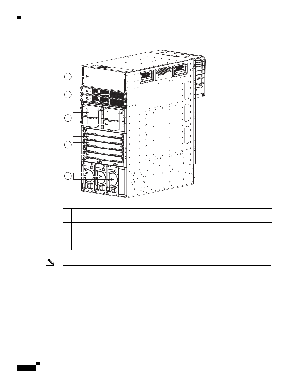
Figure 1-1 identifies the standard features on the front and sides of the Cisco Nexus 7010 chassis,
Figure 1-2 identifies the optional features on the front side of the chassis, and Figure 1-3 identifies the
standard features on the rear of the chassis.
OL-18634-01
Cisco Nexus 7000 Series Hardware Installation and Reference Guide
1-1
Page 20
Chapter 1 Overview
Cisco Nexus 7000 Series
Send document comments to nexus7k-docfeedback@cisco.com
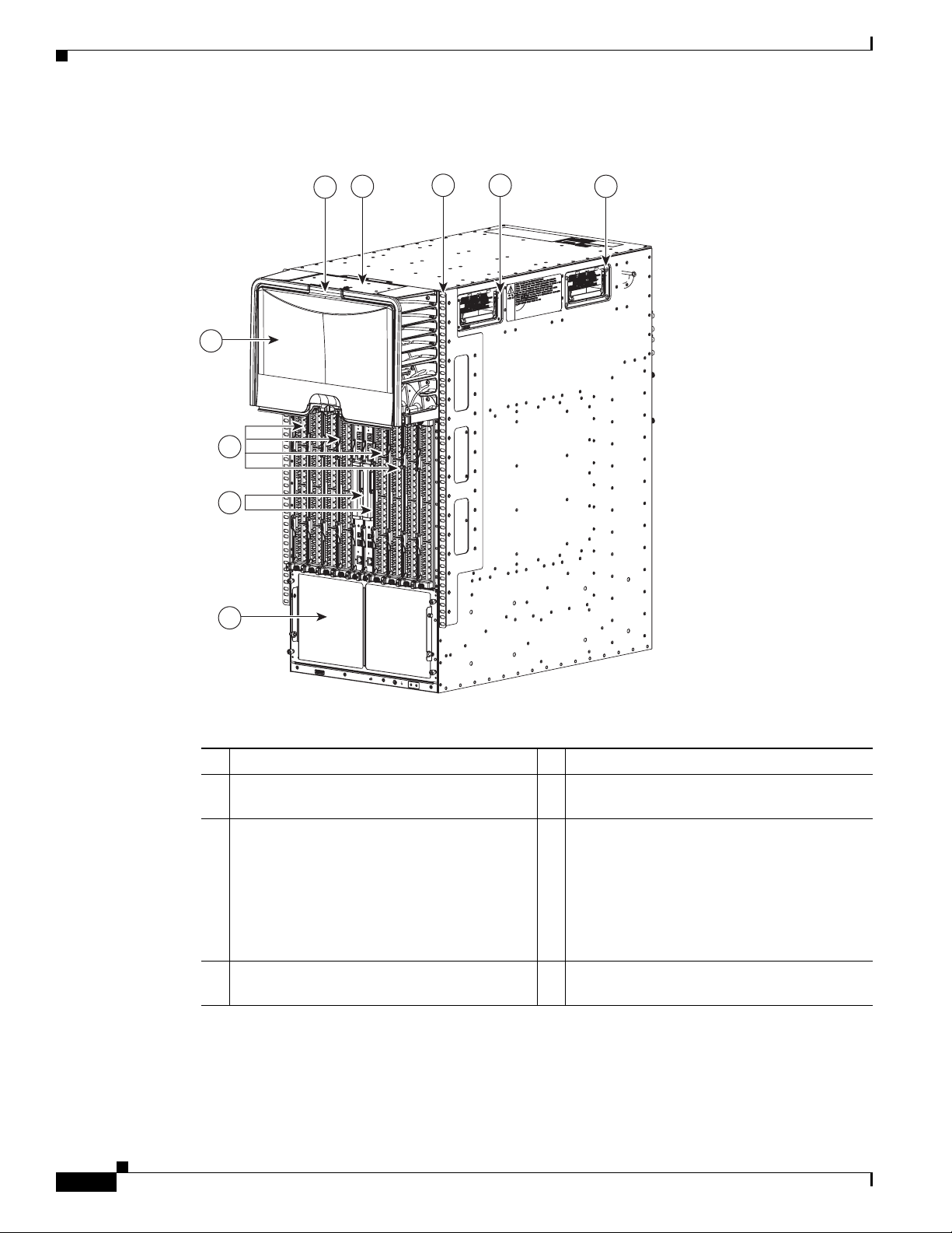
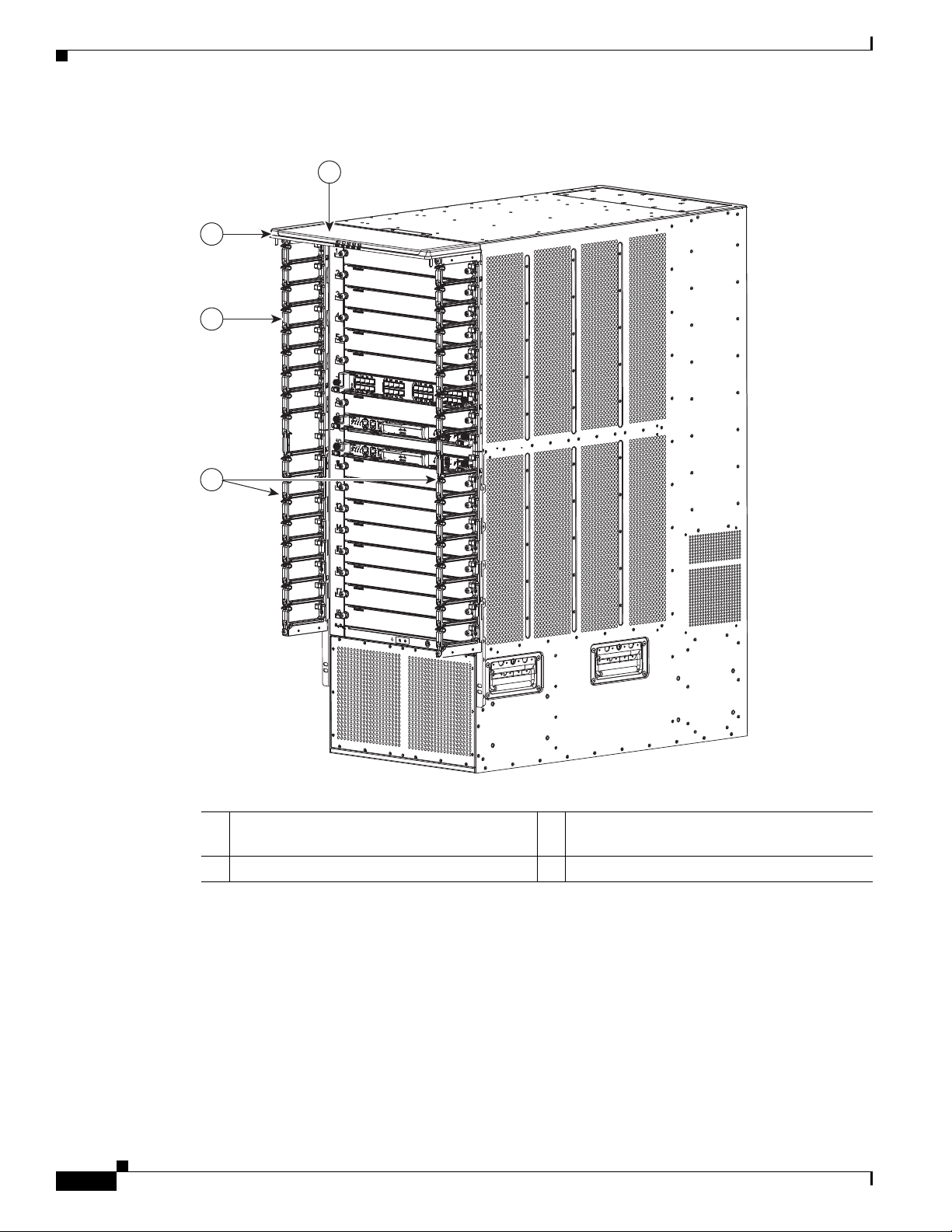
Figure 1-1 Standard Hardware Features on the Front and Sides of the Cisco Nexus 7010 Chassis
3
2
4 5
5
1
6
7
8
187117
1-2
1 Door for the cable management area 2 System status LEDs
3 Cable management area (upper routing
portion can be removed if necessary)
5 Handles used to reposition the chassis (do not
lift the chassis with these handles—use a
mechanical lift)
7 Supervisor modules (2) in slots 5 and 6 8 Air intake (shown without the optional air
Cisco Nexus 7000 Series Hardware Installation and Reference Guide
4 Rack mount bracket (2)—one on each side
6 I/O modules (1 to 8) in slots 1 to 4 and 7 to
10—these modules are a combination of the
following:
• 48-port 10/100/1000 modules
• 48-port 1-Gigabit Ethernet modules
• 32-port 10-Gigabit Ethernet modules
filter)
OL-18634-01
Page 21
Chapter 1 Overview
187142
1
2
Cisco Nexus 7000 Series
Send document comments to nexus7k-docfeedback@cisco.com
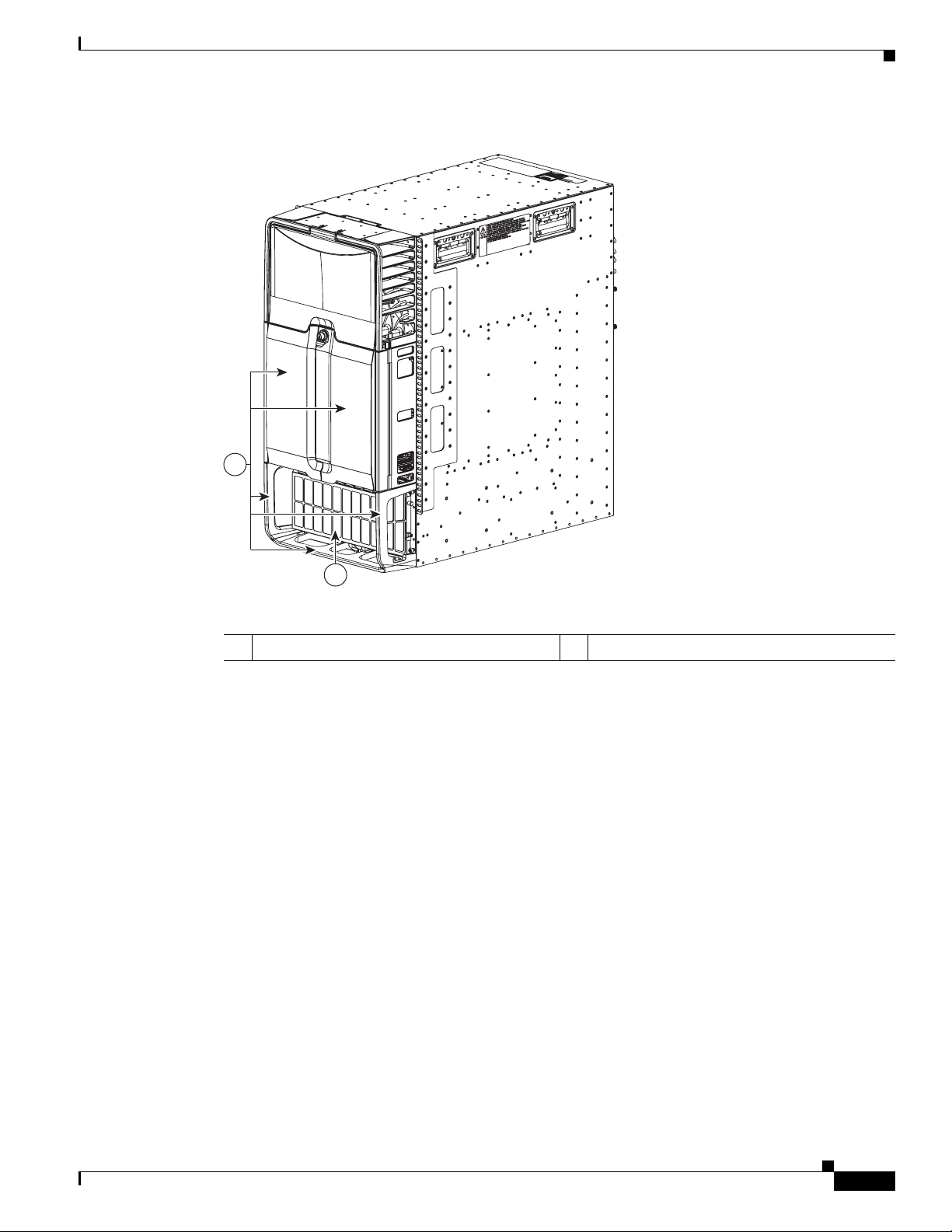
Figure 1-2 Optional Hardware Features on the Front Side of the Cisco Nexus 7010 Chassis
1 Mid-frame door assembly 2 Air filter
OL-18634-01
Cisco Nexus 7000 Series Hardware Installation and Reference Guide
1-3
Page 22
Chapter 1 Overview
Cisco Nexus 7000 Series
Send document comments to nexus7k-docfeedback@cisco.com
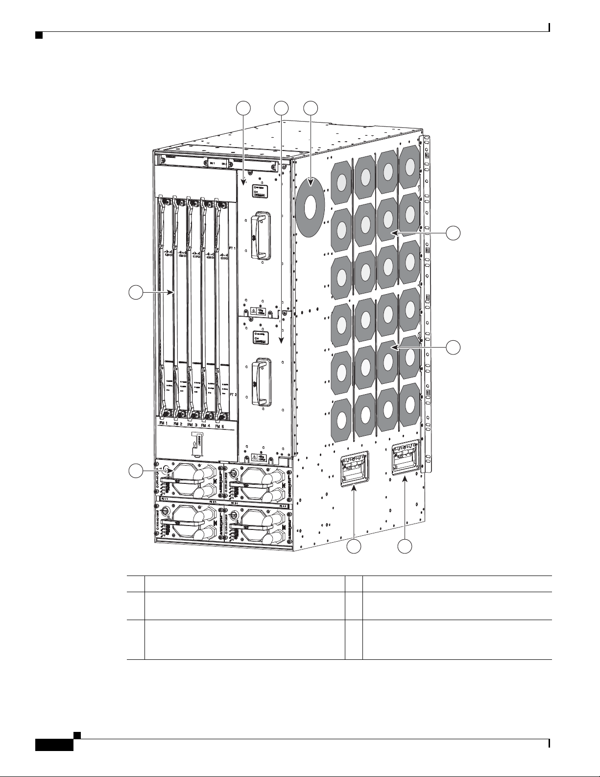
Figure 1-3 Standard Hardware Features on the Back of the Cisco Nexus 7010 Chassis
1
2
3
4
5
187118
1 Fan exhaust for the supervisor and I/O modules 2 System fan trays (2) and exhaust for the
supervisor and I/O modules
3 Fabric fan trays (2) and exhaust for the fabric
4 Fabric modules (up to 5)
modules
5 Power supply units (up to 3) and exhaust for the
power supply units
Note Figure 1-1 and Figure 1-3 show the Cisco Nexus 7000 Series chassis as it appears when it is fully
configured before including cables for connections to the Internet and the console. The systems that are
not fully configured with the maximum number of supervisor modules, I/O modules, fabric modules, or
power supply units have blank panels installed in place of the missing components to maintain the
designed airflow for system cooling.
You must install the Cisco Nexus 7010 system chassis in a four-post 19-inch EIA rack that meets the
following specifications:
1-4
• Mounting rails that conform to the English universal hole spacing as specified in
ANSI/EIA-310-D-1992.
• The minimum vertical rack space is 36.75 inches (93.3 cm) or 21 rack units (RU) for a single chassis
installation and 73.5 inches (186.6 cm) or 42 rack units for a dual-chassis installation. We
recommend that you use a 45 RU rack for a dual-chassis installation.
Cisco Nexus 7000 Series Hardware Installation and Reference Guide
OL-18634-01
Page 23
Chapter 1 Overview
187186
Install the first chassis at the
bottom of the rack for maximum
stability.
Cisco Nexus 7000 Series
Send document comments to nexus7k-docfeedback@cisco.com
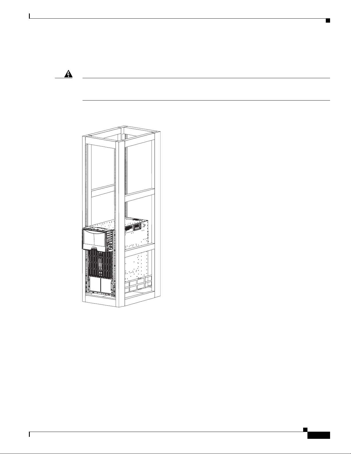
If you install one chassis, install it at the lowest possible RU on the rack for stability, as shown in
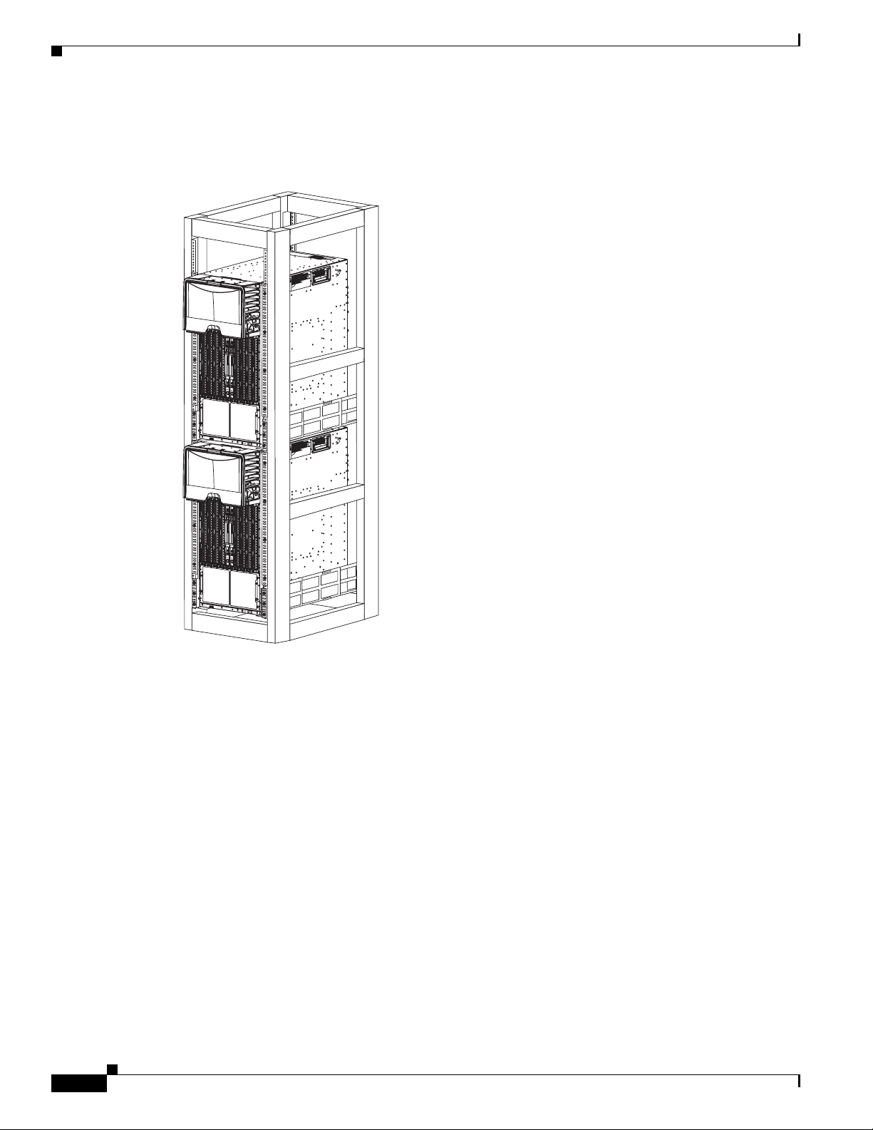
Figure 1-4. If you install two chassis in the same rack, install the bottom chassis first and then install the
other chassis on top as shown in Figure 1-5.
Warning
Stability hazard. The rack stabilizing mechanism must be in place, or the rack must be bolted to the
floor before you slide the unit out for servicing. Failure to stabilize the rack can cause the rack to tip
over.
Statement 1048
Figure 1-4 One Cisco Nexus 7010 Chassis Installed in a Four-Post Rack
OL-18634-01
Cisco Nexus 7000 Series Hardware Installation and Reference Guide
1-5
Page 24
Chapter 1 Overview
187187
Install a second chassis
immediately above the
first installed chassis.
Cisco Nexus 7000 Series
Send document comments to nexus7k-docfeedback@cisco.com
Figure 1-5 Two Cisco Nexus 7010 Chassis Installed in a Four-Post Rack
Cisco Nexus 7018 System
The Cisco Nexus 7018 chassis has 18 slots that allow for two supervisor modules and up to 16 I/O
modules. The chassis also holds up to five fabric modules, two fan trays, up to four power supply units,
and a cable management system. The chassis also has a mounting bracket and four positioning handles
(two on each side) that you use to install the chassis after you position it on a rack. Optionally, you can
include a front door to protect the I/O cable connections.
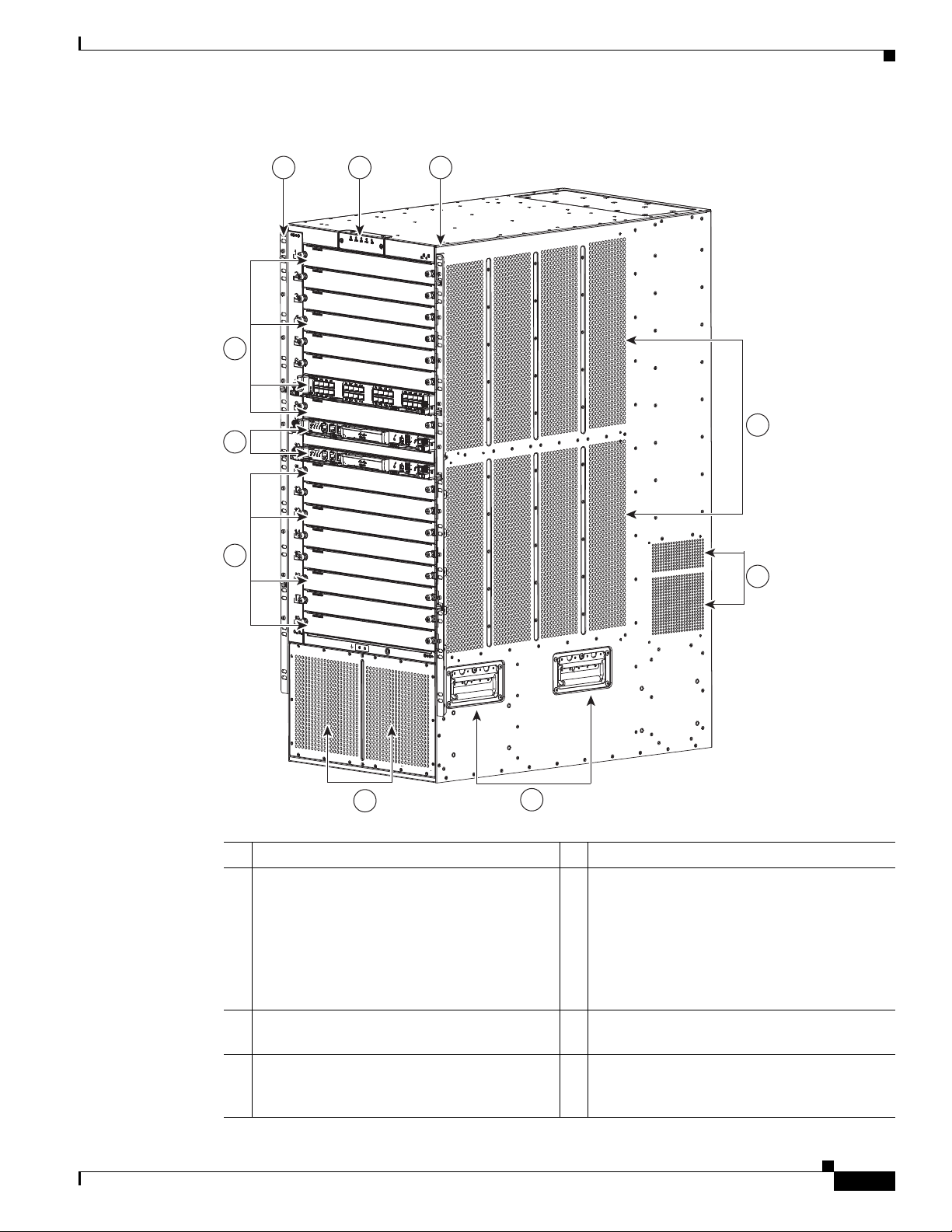
Figure 1-6 identifies the standard features on the front and sides of the Cisco Nexus 7018 chassis,
Figure 1-8 identifies the optional feature on the front side of the chassis, and Figure 1-9 identifies the
standard features on the rear of the chassis.
1-6
Cisco Nexus 7000 Series Hardware Installation and Reference Guide
OL-18634-01
Page 25
Chapter 1 Overview
189972
12 2
5
8
3
4
3
6
7
Cisco Nexus 7000 Series
Send document comments to nexus7k-docfeedback@cisco.com
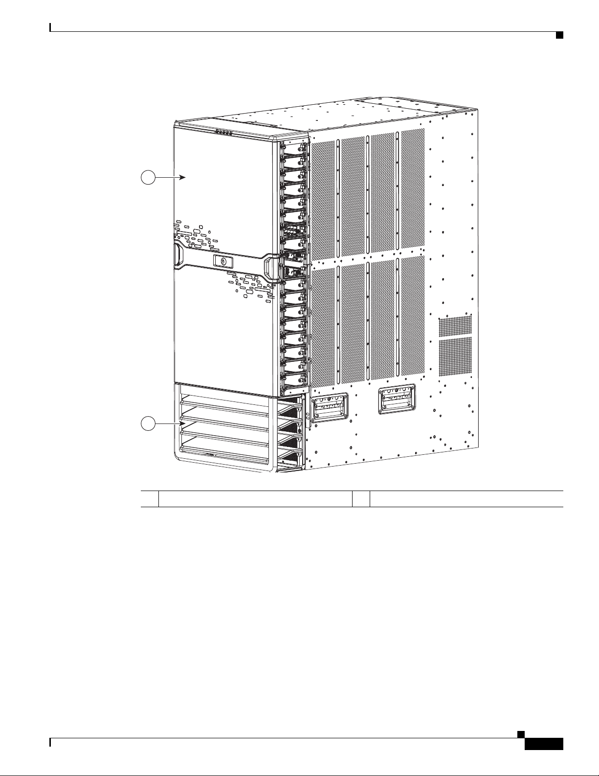
Figure 1-6 Standard Hardware Features on the Front and Sides of the Cisco Nexus 7018 Chassis
1 System status LEDs 2 Rack-mount brackets (2)
3 I/O modules (1 to 16) in slots 1 to 8 and 11 to
4 Supervisor modules (2) in slots 9 and 10
18—these modules are a combination of the
following:
• 48-port 10/100/1000 modules
• 48-port 1-Gigabit Ethernet modules
• 32-port 10-Gigabit Ethernet modules
5 Air intake for power supply units. 6 Air intake for the supervisor modules and I/O
modules.
7 Air intake for fabric modules. 8 Handles used to reposition the chassis (do not
lift the chassis with these handles—use a
mechanical lift)
OL-18634-01
Cisco Nexus 7000 Series Hardware Installation and Reference Guide
1-7
Page 26
Chapter 1 Overview
1
2
3
4
192087
Cisco Nexus 7000 Series
Send document comments to nexus7k-docfeedback@cisco.com
Figure 1-7 Cable Management System for the 7018 Chassis
1 System status LEDs (These LEDs show the
2 Top hood
system status displayed by the chassis LEDs.)
3 Upper cable management assemblies 4 Lower cable management assemblies
1-8
Cisco Nexus 7000 Series Hardware Installation and Reference Guide
OL-18634-01
Page 27
Chapter 1 Overview
1
2
192088
Cisco Nexus 7000 Series
Send document comments to nexus7k-docfeedback@cisco.com
Figure 1-8 Optional Front Door for the Cisco Nexus 7018 Chassis
1 Front doors 2 Air intake frame for power supply units
OL-18634-01
Cisco Nexus 7000 Series Hardware Installation and Reference Guide
1-9
Page 28
Chapter 1 Overview
Cisco Nexus 7000 Series
Send document comments to nexus7k-docfeedback@cisco.com
Figure 1-9 Standard Hardware Features on the Back of the Cisco Nexus 7018 Chassis
3 43
5
1
5
2
192089
6 6
1 Fabric modules (up to 5) 2 Power supply units (up to 4)
3 Fan trays for cooling the supervisor, I/O, and
4 Fan exhaust for fabric modules
fabric modules
5 Fan exhaust for supervisor and I/O modules 6 Handles used to reposition the chassis (do
not lift the chassis with these handles—use a
mechanical lift)
1-10
Cisco Nexus 7000 Series Hardware Installation and Reference Guide
OL-18634-01
Page 29
Chapter 1 Overview
Cisco Nexus 7000 Series
Send document comments to nexus7k-docfeedback@cisco.com
Note Figure 1-6 and Figure 1-9 show the Cisco Nexus 7018 chassis as it appears when it is fully configured
before including cables for connections to the Internet and the console. The systems that are not fully
configured with the maximum number of supervisor modules, I/O modules, fabric modules, or power
supply units have blank panels installed in place of the missing components to maintain the designed
airflow for system cooling.
You must install the Cisco Nexus 7018 chassis in a four-post 19-inch EIA rack that meets the following
specifications:
• Mounting rails that conform to the English universal hole spacing as specified in
ANSI/EIA-310-D-1992.
• The minimum vertical rack space is 43.75 inches (111.1 cm) or 25 rack units (RU) for a single
chassis installation and 87.5 inches (222.2 cm).
Install the Cisco Nexus 7018 chassis at the lowest possible RU on the rack for stability, as shown in
Figure 1-10. If there is another device in the rack, install the heaviest one at the bottom.
Warning
Stability hazard. The rack stabilizing mechanism must be in place, or the rack must be bolted to the
floor before you slide the unit out for servicing. Failure to stabilize the rack can cause the rack to tip
over.
Statement 1048
OL-18634-01
Cisco Nexus 7000 Series Hardware Installation and Reference Guide
1-11
Page 30
Chapter 1 Overview
192095
Preparing the Site
Send document comments to nexus7k-docfeedback@cisco.com
Figure 1-10 Cisco Nexus 7018 Chassis Installed in a Four-Post Rack
Preparing the Site
Warning
Cisco Nexus 7000 Series Hardware Installation and Reference Guide
1-12
Installation of the equipment must comply with local and national electrical codes. Statement 1074
Before you can install a Cisco Nexus 7000 Series system, you must prepare the site for the installation.
You must make sure that the altitude, temperature, humidity, air quality, airflow, electromagnetic and
radio frequency interference, floor structure, power, and earth grounding of the installation site all meet
the requirements of the Cisco Nexus 7000 Series system that you are installing. In addition, you must
OL-18634-01
Page 31

Chapter 1 Overview
Safety Guidelines
Send document comments to nexus7k-docfeedback@cisco.com
set up a rack or cabinet that can hold one or two chassis. To see the general requirements for this system,
see
Appendix A, “Technical Specifications.” To see detailed information about preparing the data center
for the installation, see the Cisco Nexus 7000 Series Site Preparation Guide.
Safety Guidelines
Warning
Only trained and qualified personnel should be allowed to install, replace, or service this equipment.
Statement 1030
The prerequisites listed for any procedure are required conditions that you must verify before you start
that procedure. If the prerequisites have not been met, you must satisfy those requirements before
carrying out the procedure.
Safety warnings appear in this publication wherever procedures present conditions that could endanger
you or others installing this system. Adhering to these warnings and following their recommended
actions are required actions for these procedures. For regulatory compliance and safety information on
these warnings, see the Cisco Nexus 7000 Series Regulatory Compliance and Safety Information
document.
Installation and Connection Guidelines
After you fully prepare the site as specified in the Cisco Nexus 7000 Series Site Preparation Guide,
install a four-post 19-inch EIA rack, and attach two bottom-support rails, you can begin installing the
Cisco Nexus 7000 Series system. To install the system, you must load the chassis onto a mechanical lift,
use the mechanical lift to position and elevate the chassis at its bottom-support rails on a rack or cabinet,
push the chassis onto the rack or cabinet, and then secure the chassis to the rack or cabinet. With the
chassis in place, you can install the power supply units and accessories and then connect the device to
the console and network. For detailed instructions on installing a Cisco Nexus 7010 device, see the
following chapters:
• Chapter 2, “Installing a Cisco Nexus 7010 Chassis.”
• Chapter 3, “Installing a Cisco Nexus 7018 Chassis.”
• Chapter 4, “Installing Power Supply Units.”
For detailed instructions on connecting the device to the console and network, see Chapter 5,
“Connecting the Cisco Nexus 7000 Device to the Network.”
Caution Do not use the handles on the side of the chassis to lift the chassis. Use these handles only for adjusting
the position of the chassis while the chassis rests on a platform or bottom-support rails.
Managing the System Hardware
After the Cisco Nexus 7000 Series system is installed and operating, you can use the Cisco NX-OS
operating system to manage the system hardware. These management functions include displaying
system and module information, setting the power supply modes, and managing module functions. For
more information about these functions, see
Cisco Nexus 7000 Series Hardware Installation and Reference Guide
OL-18634-01
Chapter 6, “Managing the Device Hardware.”
1-13
Page 32

Chapter 1 Overview
Replacing Components
Send document comments to nexus7k-docfeedback@cisco.com
Replacing Components
While the Cisco Nexus 7000 Series system is operational, you can replace any I/O module or any one of
the following components if they are redundant:
• Power supply
• Supervisor module
• Fabric module
• System fan tray
• Fabric fan tray
For detailed information on replacing these components, see Chapter 8, “Removal and Installation
Procedures.”
1-14
Cisco Nexus 7000 Series Hardware Installation and Reference Guide
OL-18634-01
Page 33

Send document comments to nexus7k-docfeedback@cisco.com
CHA PTER
2
Installing a Cisco Nexus 7010 Chassis
This chapter describes how to install a new or relocated Cisco Nexus 7010 chassis in a rack or cabinet.
For information about installing a Cisco Nexus 7018 chassis, see
7018 Chassis.” For information about installing power supply units in the Cisco Nexus 7000 Series
chassis, see Chapter 4, “Installing Power Supply Units.”
This chapter includes the following sections:
• Preparing to Install the Device, page 2-1
• Installing the Bottom-Support Rails on the Rack, page 2-3
• Installing the Chassis, page 2-7
• Grounding the Cisco Nexus 7010 Chassis, page 2-11
• Installing and Formatting CompactFlash Cards, page 2-16
Chapter 3, “Installing a Cisco Nexus
Preparing to Install the Device
This section includes the following topics:
• Required Tools, page 2-1
• Installing a Four-Post Rack or Cabinet, page 2-2
• Unpacking and Inspecting a New Device, page 2-3
Note You must set up one four-post, 19-inch EIA rack or cabinet before you can install the Cisco Nexus 7010
chassis. Make sure that you order the rack or cabinet and have it delivered before installing the chassis.
Required Tools
Before you install the Cisco Nexus 7010 chassis into a rack, make sure that you have the following tools
and equipment:
• Mechanical lift capable of lifting 550 lbs (250 kg)
• No. 1 Phillips screwdriver with torque capability
• 3/16-inch flat-blade screwdriver
• Crimping tool
OL-18634-01
Cisco Nexus 7000 Series Hardware Installation and Reference Guide
2-1
Page 34

Chapter 2 Installing a Cisco Nexus 7010 Chassis
Preparing to Install the Device
Send document comments to nexus7k-docfeedback@cisco.com
• Wire stripping tool
• Tape measure and level
• Grounding cable
Note These tools and equipment do not ship with the chassis.
Additional tools and equipment, such as an electrostatic discharge (ESD) wrist strap, that you will also
need to install the Cisco Nexus 7010 chassis, are included in the Cisco Nexus 7010 accessory kit.
Caution When you handle the Cisco Nexus 7010 chassis or its components, you must follow ESD protocol at all
times to prevent ESD damage. This protocol includes but is not limited to wearing an ESD wrist strap
that you connect to the earth ground.
Note For a list of tools required to assemble and secure the four-post rack or cabinet, see the documentation
that the manufacturer shipped with the rack or cabinet.
Installing a Four-Post Rack or Cabinet
Before you install the Cisco Nexus 7010 chassis, you must install a standard four-post, 19-inch EIA data
center rack (or a cabinet that contains such a rack) that meets the requirements listed in the Cisco Nexus
7000 Series Site Preparation Guide. To maximize safety, you should do the following for the rack:
• Bolt the rack to the concrete subfloor before moving the Cisco Nexus 7010 chassis onto it.
Warning
Warning
Stability hazard. The rack stabilizing mechanism must be in place, or the rack must be bolted to the
floor before you slide the unit out for servicing. Failure to stabilize the rack can cause the rack to tip
over.
Statement 1048
• If the rack has bonded construction, connect it to the earth ground to enable you to easily ground the
system components that you install and to ground your ESD wrist strap. This step minimizes the
chance of electrostatic discharge when you handle ungrounded components before you install them.
Be sure that the rack includes AC power receptacles with the amperage required for the power supply
units that you will be installing in the chassis. If you are installing 6-kW power supply units, you must
have 20A circuits. If you are installing 7.5-kW power supply units, you must have 30A circuits.
Take care when connecting units to the supply circuit so that wiring is not overloaded.
For instructions on setting up the rack, see the documentation that the manufacturer shipped with the
rack.
Statement 1018
2-2
Cisco Nexus 7000 Series Hardware Installation and Reference Guide
OL-18634-01
Page 35

Chapter 2 Installing a Cisco Nexus 7010 Chassis
Installing the Bottom-Support Rails on the Rack
Send document comments to nexus7k-docfeedback@cisco.com
Unpacking and Inspecting a New Device
Before you install a new Cisco Nexus 7010 chassis, you need to unpack and inspect it to be sure that you
have all the items that you ordered and verify that the device was not damaged during shipment. If
anything is damaged or missing, contact your customer representative immediately.
Tip Do not discard the shipping container when you unpack the Cisco Nexus 7010 system. Flatten the
shipping cartons and store them with the pallet used for the system. If you need to move or ship the
system in the future, you will need these containers. For repacking instructions, see
“Repacking the Cisco Nexus 7000 Series Device for Shipment.”
To inspect the shipment, follow these steps:
Step 1 Compare the shipment to the equipment list provided by your customer service representative and verify
that you have received all of the ordered items. The shipment should include boxes for the following:
• System chassis, which includes the following components:
–
2 supervisor modules
Appendix D,
–
1 to 8 I/O modules
–
3 to 5 fabric modules
–
2 system fan trays
–
2 fabric fan trays
• 2 to 3 power supply units
The power supply units are shipped with the chassis but boxed separately.
• Cisco Nexus 7010 system accessory kit
To see a list of what is in the accessory kit, see the Cisco Nexus 7010 System Accessory Kit Contents
document, which is included in the kit.
• Mid-chassis doors and frame (optional)
• Air filter (optional)
Step 2 Check the contents of each box or package for damage.
Step 3 If you notice any discrepancies or damage, send the following information to your customer service
representative by e-mail:
• Invoice number of the shipper (see the packing slip)
• Model and serial number of the missing or damaged unit
• Description of the problem and how it affects the installation
Installing the Bottom-Support Rails on the Rack
The bottom-support rails hold the Cisco Nexus 7010 chassis on the rack or cabinet. To maximize the
stability of the rack, you must attach these rails at the lowest possible rack unit (RU).
Cisco Nexus 7000 Series Hardware Installation and Reference Guide
OL-18634-01
2-3
Page 36

Chapter 2 Installing a Cisco Nexus 7010 Chassis
Installing the Bottom-Support Rails on the Rack
Send document comments to nexus7k-docfeedback@cisco.com
The prerequisites, tools, and process for installing the bottom-support rails are included in the following
topics:
• Prerequisites for Attaching the Bottom-Support Rails, page 2-4
• Required Tools and Equipment, page 2-4
• Attaching the Bottom-Support Rails, page 2-4
Prerequisites for Attaching the Bottom-Support Rails
Before you can attach the bottom-support rails, you must fully install the rack or cabinet, and should, for
maximum stability, bolt the rack or cabinet to the concrete subfloor. If anything lighter than the Cisco
Nexus 7010 system is already installed in the rack, you should make sure that it is positioned above
where you will be installing the Cisco Nexus 7010 system. Also, you must have the bottom-support rail
kit, which ships with the Cisco Nexus 7010 system accessory kit. The distance between the front and
rear mounting brackets on the rack or cabinet must be between 24 and 36 inches (60.96 and 81.28
to fit the bottom-support rails.
cm)
Required Tools and Equipment
You need the following tools and equipment to attach the bottom-support rails:
• No. 1 Phillips screwdriver.
• Rack-mount kit (shipped with the accessory kit). Ta ble 2-1 lists the items in the rack-mount kit.
Ta b l e 2-1 Contents for the Rack-Mount Kit
Part Description Quantity
12-24 x 3/4 in. Phillips screws 20
M6 x 19 mm Phillips screws 20
Adjustable bottom-support rails 2
Attaching the Bottom-Support Rails
To maximize the stability of the rack, you should install the chassis as low as possible on the rack. Install
the heaviest system first at the bottom of the rack. If you install a second system in the same rack, install
it immediately above the lower system if there is enough vertical space.
2-4
Cisco Nexus 7000 Series Hardware Installation and Reference Guide
OL-18634-01
Page 37

Chapter 2 Installing a Cisco Nexus 7010 Chassis
Installing the Bottom-Support Rails on the Rack
Send document comments to nexus7k-docfeedback@cisco.com
Warning
To prevent bodily injury when mounting or servicing this unit in a rack, you must take special
precautions to ensure that the system remains stable. The following guidelines are provided to
ensure your safety:
• This unit should be mounted at the bottom of the rack if it is the only unit in the rack.
• When mounting this unit in a partially filled rack, load the rack from the bottom to the top with the heaviest
component at the bottom of the rack.
• If the rack is provided with stabilizing devices, install the stabilizers before mounting or servicing the unit in
the rack.
Statement 1006
To attach the bottom-support rails to a four-post EIA rack, follow these steps:
Step 1 Position one of the two adjustable bottom-support rails at the lowest possible RU. If you are installing a
chassis above another Cisco Nexus 7010 chassis, position the rail 36.75
the bottom-support rails for the lower chassis as shown in
Figure 2-1. Adjust the length of the rail so that
inches (93.4 cm) (21 RU) above
it stretches from the outer edges of the front and rear vertical mounting rails. You can expand the rail so
that its mounting brackets are spaced between 24 to 32
inches (60.96 to 81.28 cm).
OL-18634-01
Cisco Nexus 7000 Series Hardware Installation and Reference Guide
2-5
Page 38

Chapter 2 Installing a Cisco Nexus 7010 Chassis
3
1
2
187183
3
Installing the Bottom-Support Rails on the Rack
Send document comments to nexus7k-docfeedback@cisco.com
Figure 2-1 Positioning the Bottom-Support Rails
2-6
1 For the first and heaviest Cisco Nexus 7010
chassis installed in a rack, position two
bottom-support rails at the lowest RU on the
rack.
2 For the second Cisco Nexus 7010 chassis
installed in a rack, position two
bottom-support rails immediately above the
first installed device.
3 Allow at least 36.75 inches (93.4 cm) (21 RU)
for each Cisco Nexus 7010 system.
Step 2 Use a Phillips screwdriver to screw in three M6 x 19 mm or 12-24 x 3/4 in. Phillips screws on each end
of each rail (using a total of 12 screws for both brackets) as shown in
Figure 2-2.
Cisco Nexus 7000 Series Hardware Installation and Reference Guide
OL-18634-01
Page 39

Chapter 2 Installing a Cisco Nexus 7010 Chassis
186690
1
1
1
1
2
2
Installing the Chassis
Send document comments to nexus7k-docfeedback@cisco.com
Figure 2-2 Attaching a Bottom-Support Rail to a Rack
1 Four sets of 3 M6 x 19 mm Phillips screws or
four sets of 3 12-24 x 3/4 in. Phillips screws
2 Adjustable bottom-support rails (2)
Installing the Chassis
This section describes how to install the Cisco Nexus 7010 chassis in a rack or cabinet. These installation
steps include transporting the chassis, elevating the chassis to the rack using a mechanical lift, pushing
the chassis onto the rack, and then securing the chassis to the rack.
This section includes the following topics:
• Prerequisites for Installing the Chassis, page 2-8
• Required Tools and Equipment, page 2-8
• Installing the Chassis, page 2-9
OL-18634-01
Cisco Nexus 7000 Series Hardware Installation and Reference Guide
2-7
Page 40

Chapter 2 Installing a Cisco Nexus 7010 Chassis
Installing the Chassis
Send document comments to nexus7k-docfeedback@cisco.com
Prerequisites for Installing the Chassis
Before you install the chassis, you must make sure that the following items are available for the
installation:
• Data center ground is accessible where you are installing the Cisco Nexus 7010 chassis
• Four-post, 19-inch, EIA rack or cabinet that includes such a rack
For more information on the rack or cabinet, see the “Installing a Four-Post Rack or Cabinet” section
on page 2-2.
Warning
Warning
Stability hazard. The rack stabilizing mechanism must be in place, or the rack must be bolted to the
floor before you slide the unit out for servicing. Failure to stabilize the rack can cause the rack to tip
over.
Statement 1048
• Bottom-support rails installed in the rack or cabinet—You must already have two bottom-support
rails attached to the lowest possible rack unit on the chassis.
For more information, see the “Installing the Bottom-Support Rails on the Rack” section on
page 2-3.
To prevent bodily injury when mounting or servicing this unit in a rack, you must take special
precautions to ensure that the system remains stable. The following guidelines are provided to
ensure your safety:
• This unit should be mounted at the bottom of the rack if it is the only unit in the rack.
• When mounting this unit in a partially filled rack, load the rack from the bottom to the top with the heaviest
component at the bottom of the rack.
• If the rack is provided with stabilizing devices, install the stabilizers before mounting or servicing the unit in
the rack.
• Cisco Nexus 7010 chassis and its components are accounted for and undamaged
Statement 1006
For more information, see the “Unpacking and Inspecting a New Device” section on page 2-3.
Required Tools and Equipment
You need the following tools and equipment to install the Cisco Nexus 7010 chassis:
• Mechanical lift capable of lifting at least 550 lbs (250 kg)
• No. 1 Phillips screwdriver
• Bottom-support rails kit (shipped with the Cisco Nexus 7010 system accessory kit)
Part of this kit has already been used to install the bottom-support rails. Table 2-2 lists the items in
the rack-mount kit.
Cisco Nexus 7000 Series Hardware Installation and Reference Guide
2-8
OL-18634-01
Page 41

Chapter 2 Installing a Cisco Nexus 7010 Chassis
Installing the Chassis
Send document comments to nexus7k-docfeedback@cisco.com
Ta b l e 2-2 Contents for the Rack-Mount Kit
Part Description Quantity
12-24 x 3/4 in. Phillips screws 20
M6 x 19 mm Phillips screws 20
Adjustable bottom-support rails 2
Note You should also have at least four people to push the chassis, which can weigh up to 550 lbs (250 kg),
onto and off the mechanical lift and rack.
Installing the Chassis
To install a Cisco Nexus 7010 chassis in a four-post rack or cabinet, follow these steps:
Step 1 Load the chassis onto a mechanical lift as follows:
a. Position the mechanical lift next to the shipping pallet that holds the chassis.
b. Elevate the lift platform to the level of the bottom of the chassis (or no more than 1/4 inch [0.635 cm]
below the bottom of the chassis).
c. Use at least four persons to slide the chassis fully onto the lift so that the side of the chassis touches
or is close to the vertical rails on the lift. Make sure that the front and rear of the chassis are
unobstructed so you can easily push the chassis into the rack.
Warning
Caution To lift the chassis, use a mechanical lift, not the handles on the side of the chassis. Use the side handles
To prevent personal injury or damage to the chassis, never attempt to lift or tilt the chassis using the
handles on modules (such as power supplies, fans, or cards); these types of handles are not designed
to support the weight of the unit.
Statement 1032
for only repositioning the chassis after it is already on the mechanical lift or in the rack or cabinet.
Step 2 Use the mechanical lift to move and align the rear of the chassis to the front of the four-post rack or
cabinet. Make sure that the bottom of the chassis is elevated to the height of the bottom-support rails or
no more than 1/4 inch (0.635 cm) above the bracket.
Step 3 Use at least four persons to push the chassis onto the installed bottom-support rails as shown in
Figure 2-3.
OL-18634-01
Push the lower half of the front side of the chassis so that the back side enters the rack first, and push
until the chassis mounting brackets come in contact with the front vertical mounting rails on the rack.
Cisco Nexus 7000 Series Hardware Installation and Reference Guide
2-9
Page 42

Chapter 2 Installing a Cisco Nexus 7010 Chassis
Installing the Chassis
Send document comments to nexus7k-docfeedback@cisco.com
Figure 2-3 Moving a Cisco Nexus 7010 Chassis onto a Rack
3
3
2
1
1 Push the lower half of the front side of the
2
1
187184
2 Chassis mounting brackets
chassis
3 Rack vertical mounting rails
Step 4 Make sure that the screw holes in the chassis mounting brackets align with the screw holes in the vertical
mounting rails.
If you need to reposition the chassis to align the screw holes, you can use the handles on the sides of the
chassis.
2-10
Tip To adjust the placement of the chassis so that the screw holes in the chassis mounting brackets align with
the screw holes in the vertical mounting rails, use the chassis handles shown in Figure 2-4.
Step 5 Use a Phillips screwdriver to screw in four M6 x 19-mm or 12-24 x 3/4-inch screws in each of the two
chassis mounting brackets (use a total of eight screws for two mounting brackets) as shown in
Cisco Nexus 7000 Series Hardware Installation and Reference Guide
Figure 2-4.
OL-18634-01
Page 43

Chapter 2 Installing a Cisco Nexus 7010 Chassis
187185
2
2
2
2
1
1
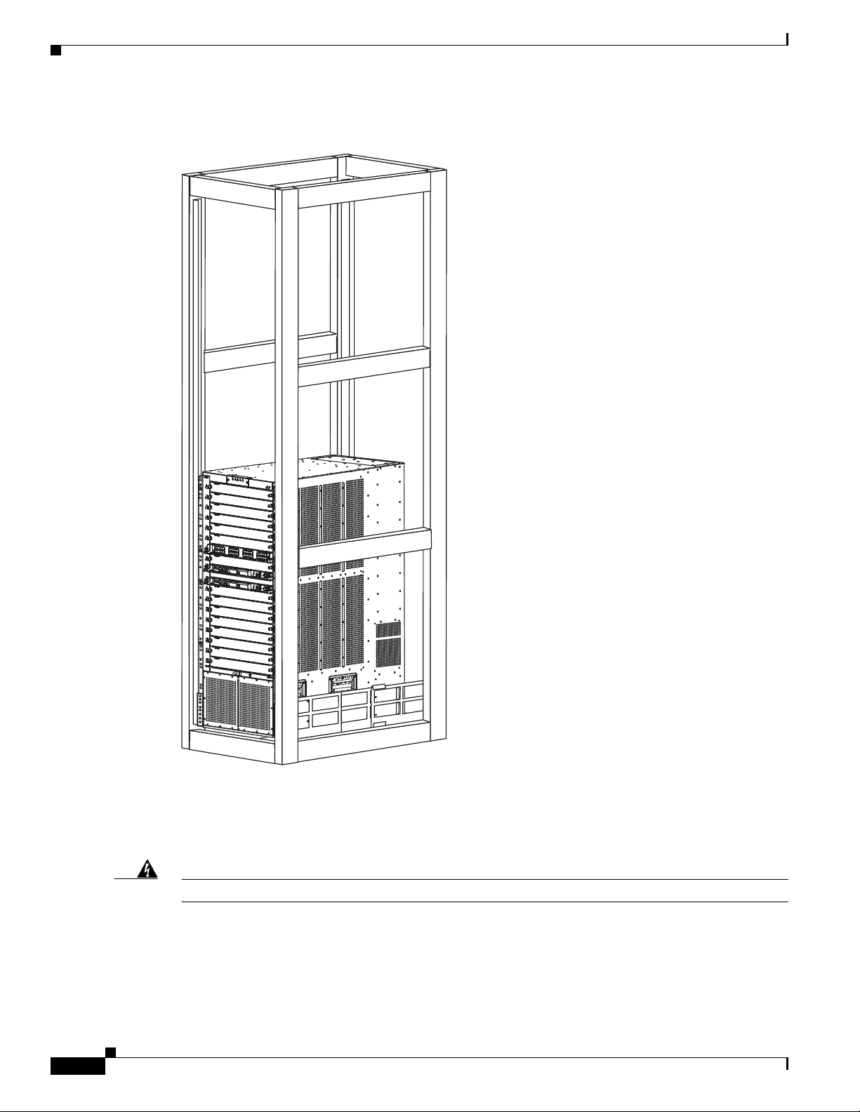
Grounding the Cisco Nexus 7010 Chassis
Send document comments to nexus7k-docfeedback@cisco.com
Figure 2-4 Attaching the Cisco Nexus 7010 Chassis to the Rack
1 Handles used to adjust the chassis placement. 2 Four M6 x 19 mm or 10-24 x 3/4 in. Phillips
Grounding the Cisco Nexus 7010 Chassis
The Cisco Nexus 7010 system is grounded through the AC power supply cables and one of two
grounding connections on the chassis. The AC power supply cables provide a connection to an earth
ground whenever you connect the AC power to the system. The system ground, also referred to as the
network equipment building system (NEBS) ground, provides additional grounding for EMI shielding
requirements and for the low-voltage supplies (DC-DC converters) on the modules. This grounding
system is active even when the AC power cables are not connected to the system. You establish this
ground by connecting one of the two grounding pads on the chassis to the rack (if it is connected to an
earth ground) or directly to the earth ground for the data center building.
This section includes the following topics:
• Prerequisites for Grounding the Chassis, page 2-12
• Required Tools and Equipment, page 2-12
• Connecting the System Ground, page 2-12
• Connecting Your ESD Strap to the Chassis, page 2-14
screws used to attach each side bracket to a
front mounting rail (use a total of eight
screws)
Cisco Nexus 7000 Series Hardware Installation and Reference Guide
OL-18634-01
2-11
Page 44

Chapter 2 Installing a Cisco Nexus 7010 Chassis
1
2
Grounding the Cisco Nexus 7010 Chassis
Send document comments to nexus7k-docfeedback@cisco.com
Prerequisites for Grounding the Chassis
Before you can ground the chassis, you must have a connection to the earth ground for the data center
building. If you installed the Cisco Nexus 7010 chassis into a bonded rack (see the rack manufacturer’s
instructions for more information) that now has a connection to the data center earth ground, you can
ground the chassis by connecting its grounding ports to the rack. Otherwise, you must connect the
chassis grounding ports directly to the data center ground.
Required Tools and Equipment
To connect the system ground, you need the following tools and materials:
• Grounding lug—A two-holed standard barrel lug that supports up to 6 AWG wire. This lug is
supplied with the Cisco Nexus 7010 system accessory kit.
• Grounding screws—Two M4 x 8 mm (metric) pan-head screws. These screws are shipped with the
Cisco Nexus 7010 accessory kit.
• Grounding wire—Not supplied with the Cisco Nexus 7010 system accessory kit. This wire should
be sized to meet local and national installation requirements. Depending on the power supply and
system, a 12 AWG to 6 AWG copper conductor is required for U.S. installations. We recommend
that you use commercially available 6 AWG wire. The length of the grounding wire depends on the
proximity of the switch to proper grounding facilities.
• No. 1 Phillips screwdriver.
• Crimping tool to crimp the grounding wire to the grounding lug.
• Wire-stripping tool to remove the insulation from the grounding wire.
Connecting the System Ground
After you have moved the chassis into the rack or cabinet, you are ready to connect the system to the
data center earth ground. After you ground the chassis, you can ground your ESD wrist strap by
connecting it to the chassis.
To connect the system ground to the data center earth ground, follow these steps:
Step 1 Use a wire-stripping tool to remove approximately 0.75 inch (19 mm) of the covering from the end of
the grounding wire.
Step 2 Insert the stripped end of the grounding wire into the open end of the grounding lug as shown in
Figure 2-5.
Figure 2-5 Inserting the Grounding Wire in the Grounding Lug
Cisco Nexus 7000 Series Hardware Installation and Reference Guide
2-12
OL-18634-01
Page 45

Chapter 2 Installing a Cisco Nexus 7010 Chassis
187225
Grounding port
Grounding the Cisco Nexus 7010 Chassis
Send document comments to nexus7k-docfeedback@cisco.com
1 NRTL listed 45-degree grounding lug 2 Grounding cable with 0.75 in. of insulation stripped
from the end
Step 3 Use the crimping tool to crimp the lug to the grounding wire. Verify that the ground wire is securely
attached to the ground lug by attempting to pull the wire out of the crimped lug.
Step 4 Remove the adhesive label from one of the two system grounding pads, and secure the grounding wire
lug to the grounding pad with two M4 screws.
the front side of the chassis. Figure 2-7 shows the location on the rear of the chassis. Ensure that the
grounding lug and the grounding wire do not interfere with other device hardware or rack equipment.
Figure 2-6 Grounding Port on the Front of the Cisco Nexus 7010 Chassis
Figure 2-6 shows the location of the grounding pads on
OL-18634-01
Cisco Nexus 7000 Series Hardware Installation and Reference Guide
2-13
Page 46

Chapter 2 Installing a Cisco Nexus 7010 Chassis
18 7227
Ground
port
Grounding the Cisco Nexus 7010 Chassis
Send document comments to nexus7k-docfeedback@cisco.com
Figure 2-7 Grounding Port on the Rear of the Cisco Nexus 7010 Chassis
Step 5 Prepare the other end of the grounding wire and connect it to an appropriate grounding point in your site
to ensure an adequate earth ground for the device. If the rack is grounded, connect the grounding wire
as explained in the documentation provided by the vendor for the rack.
Connecting Your ESD Strap to the Chassis
After you connect the chassis to the data center earth ground, you can ground your ESD strap by
plugging it into any one of three ESD ports shown in
of the chassis).
Figure 2-8 (front of the chassis) or Figure 2-9 (rear
2-14
Cisco Nexus 7000 Series Hardware Installation and Reference Guide
OL-18634-01
Page 47

Chapter 2 Installing a Cisco Nexus 7010 Chassis
187224
ESD port
ESD port
Grounding the Cisco Nexus 7010 Chassis
Send document comments to nexus7k-docfeedback@cisco.com
Figure 2-8 ESD Grounding Ports on the Front of the Cisco Nexus 7010 Chassis
OL-18634-01
Cisco Nexus 7000 Series Hardware Installation and Reference Guide
2-15
Page 48

Chapter 2 Installing a Cisco Nexus 7010 Chassis
187226
ESD port
Installing and Formatting CompactFlash Cards
Send document comments to nexus7k-docfeedback@cisco.com
Figure 2-9 ESD Grounding Port on the Rear of the Cisco Nexus 7010 Chassis
Installing and Formatting CompactFlash Cards
Each supervisor module on a Cisco Nexus 7000 Series device is shipped with a CompactFlash card
installed in the LOG FLASH reader. The EXPANSION FLASH reader is left empty, but you can
optionally install a card in that reader. For the card to function with the reader, you must make sure that
it is either formatted for the reader before installing it or format it after installing it.
Note The LOG FLASH and EXPANSION FLASH readers require different formats for their cards.
To replace an installed CompactFlash card, see the “Replacing a CompactFlash Card” section on
page 8-15.
To install a CompactFlash card, follow these steps:
Step 1 Align the card with the slot for the CompactFlash reader slot labeled LOG FLASH or EXPANSION
FLASH as shown in
card that goes into the reader first.
Cisco Nexus 7000 Series Hardware Installation and Reference Guide
2-16
Figure 2-10. The grooves on the thin side of the card must begin on the end of the
OL-18634-01
Page 49

Chapter 2 Installing a Cisco Nexus 7010 Chassis
Installing and Formatting CompactFlash Cards
Send document comments to nexus7k-docfeedback@cisco.com
Figure 2-10 Aligning a CompactFlash Card to its Reader
189555
Step 2 Push the card all the way into the reader.
If the card does not fit easily into the reader, flip the card so the bottom edge is on top, and try pushing
the card into the reader.
Step 3 Wait for the reader LED to turn green and for a message to appear on the console as follows:
• If you are installing a card into the log flash reader, the message will end with “logflash:online.”
switch# 2008 Mar 15 08:00:00 switch %$ VDC-1 %$ %IDEHSD-2-MOUNT: logflash:online
• If you are installing a card into the expansion flash reader, the message will end with “slot0:online.”
switch# 2008 Mar 15 08:00:00 switch %$ VDC-1 %$ %IDEHSD-2-MOUNT: slot0:online
• If you see an offline message or do not see a message, either the card is not fully pushed into the
reader or it is improperly formatted.
switch# 2008 Dec 1 12:00:00 switch %$ VDC-1 %$ %IDEHSD-2-UMOUNT:logflash:offline
Make sure that the card is fully inserted inside the reader. If the card is fully inserted, either format
the card (see the Cisco NX-OS Fundamentals Configuration Guide, Release 4.0) or replace the card
with another card that is properly formatted for the reader (see the
“Replacing a CompactFlash
Card” section on page 8-15).
OL-18634-01
Cisco Nexus 7000 Series Hardware Installation and Reference Guide
2-17
Page 50

Chapter 2 Installing a Cisco Nexus 7010 Chassis
Installing and Formatting CompactFlash Cards
Send document comments to nexus7k-docfeedback@cisco.com
2-18
Cisco Nexus 7000 Series Hardware Installation and Reference Guide
OL-18634-01
Page 51

Send document comments to nexus7k-docfeedback@cisco.com
CHA PTER
3
Installing a Cisco Nexus 7018 Chassis
This chapter describes how to install a new or relocated Cisco Nexus 7018 chassis in a rack or cabinet.
For information about installing a Cisco Nexus 7010 chassis, see
7010 Chassis.” For information about installing power supply units in the Cisco Nexus 7000 Series
chassis, see Chapter 4, “Installing Power Supply Units.”
This chapter includes the following sections:
• Preparing to Install the Device, page 3-1
• Installing the Bottom-Support Rails on the Rack, page 3-3
• Installing the Chassis, page 3-6
• Grounding the Cisco Nexus 7018 Chassis, page 3-11
• Installing the Cable Management Assemblies, page 3-14
• Installing the Front Door and Air Intake Frame, page 3-19
• Installing and Formatting CompactFlash Cards, page 3-29
Chapter 2, “Installing a Cisco Nexus
Preparing to Install the Device
This section includes the following topics:
• Required Tools, page 3-1
• Installing a Four-Post Rack or Cabinet, page 3-2
• Unpacking and Inspecting a New Chassis, page 3-3
Note You must have one four-post, 19-inch EIA rack or cabinet before you can install the Cisco Nexus 7018
chassis. Make sure that you order the rack or cabinet and have it delivered before installing the chassis.
Required Tools
Before you install the Cisco Nexus 7018 chassis into a rack, make sure that you have the following tools
and equipment:
• Mechanical lift capable of lifting 700 lbs (318 kg)
• No. 1 Phillips screwdriver with torque capability
OL-18634-01
Cisco Nexus 7000 Series Hardware Installation and Reference Guide
3-1
Page 52

Chapter 3 Installing a Cisco Nexus 7018 Chassis
Preparing to Install the Device
Send document comments to nexus7k-docfeedback@cisco.com
• 3/16-inch flat-blade screwdriver
• Crimping tool
• Wire stripping tool
• Tape measure and level
• Grounding cable
Note These tools and equipment do not ship with the chassis.
Additional tools and equipment, such as an electrostatic discharge (ESD) wrist strap, that you will also
need to install the Cisco Nexus 7018 chassis, are included in the Cisco Nexus 7018 accessory kit.
Caution When you handle the Cisco Nexus 7018 chassis or its components, you must follow ESD protocol at all
times to prevent ESD damage. This protocol includes but is not limited to wearing an ESD wrist strap
that you connect to the earth ground.
Note For a list of tools required to assemble and secure the four-post rack or cabinet, see the documentation
that the manufacturer shipped with the rack or cabinet.
Installing a Four-Post Rack or Cabinet
Before you install the device, you must install a standard four-post, 19-inch EIA data center rack (or in
a cabinet that contains such a rack) that meets the requirements listed in the Cisco Nexus 7000 Series
Site Preparation Guide. To maximize safety, you should do the following for the rack:
• Bolt the rack to the concrete subfloor before moving the Cisco Nexus 7018 chassis onto it.
Warning
Stability hazard. The rack stabilizing mechanism must be in place, or the rack must be bolted to the
floor before you slide the unit out for servicing. Failure to stabilize the rack can cause the rack to tip
over.
Statement 1048
• If the rack has bonded construction, connect it to the earth ground to enable you to easily ground the
system components that you install and to ground your ESD wrist strap. This step minimizes the
chance of electrostatic discharge when you handle ungrounded components before you install them.
Be sure that the rack includes AC power receptacles with the amperage required for the power supply
units that you will be installing in the chassis. If you are installing 6-kW power supply units, you must
have 20A circuits. If you are installing 7.5-kW power supply units, you must have 30A circuits.
3-2
Warning
Take care when connecting units to the supply circuit so that wiring is not overloaded.
For instructions on setting up the rack, see the documentation that the manufacturer shipped with the
rack.
Cisco Nexus 7000 Series Hardware Installation and Reference Guide
Statement 1018
OL-18634-01
Page 53

Chapter 3 Installing a Cisco Nexus 7018 Chassis
Installing the Bottom-Support Rails on the Rack
Send document comments to nexus7k-docfeedback@cisco.com
Unpacking and Inspecting a New Chassis
Before you install a new Cisco Nexus 7018 chassis, you need to unpack and inspect it to be sure that you
have all the items that you ordered and verify that the device was not damaged during shipment. If
anything is damaged or missing, contact your customer representative immediately.
Tip Do not discard the shipping container when you unpack the Cisco Nexus 7018 system. Flatten the
shipping cartons and store them with the pallet used for the system. If you need to move or ship the
system in the future, you will need these containers. For repacking instructions, see
“Repacking the Cisco Nexus 7000 Series Device for Shipment.”
To inspect the shipment, follow these steps:
Step 1 Compare the shipment to the equipment list provided by your customer service representative and verify
that you have received all of the ordered items. The shipment should include boxes for the following:
• System chassis, which includes the following components:
–
2 supervisor modules
Appendix D,
–
1 to 16 I/O modules
–
3 to 5 fabric modules
–
2 fan trays
• 2 to 4 power supply units
The power supply units are shipped with the chassis but boxed separately.
• Cisco Nexus 7018 system accessory kit
To see a list of what is in the accessory kit, see the Cisco Nexus 7018 System Accessory Kit Contents
document, which is included in the kit.
• Front door (optional)
Step 2 Check the contents of each box or package for damage.
Step 3 If you notice any discrepancies or damage, send the following information to your customer service
representative by e-mail:
• Invoice number of the shipper (see the packing slip)
• Model and serial number of the missing or damaged unit
• Description of the problem and how it affects the installation
Installing the Bottom-Support Rails on the Rack
The bottom-support rails hold the Cisco Nexus 7018 chassis on the rack or cabinet. To maximize the
stability of the rack, you must attach these rails at the lowest possible rack unit (RU).
The prerequisites, tools, and process for installing the bottom-support rails are included in the following
topics:
• Prerequisites for Attaching the Bottom-Support Rails, page 3-4
Cisco Nexus 7000 Series Hardware Installation and Reference Guide
OL-18634-01
3-3
Page 54

Chapter 3 Installing a Cisco Nexus 7018 Chassis
Installing the Bottom-Support Rails on the Rack
Send document comments to nexus7k-docfeedback@cisco.com
• Required Tools and Equipment, page 3-4
• Attaching the Bottom-Support Rails, page 3-4
Prerequisites for Attaching the Bottom-Support Rails
Before you can attach the bottom-support rails, you must fully install the rack or cabinet, and should, for
maximum stability, bolt the rack or cabinet to the concrete subfloor. If anything lighter than the Cisco
Nexus 7018 system is already installed in the rack, you should make sure that it is positioned above
where you will be installing the Nexus 7000 Series system. Also, you must have the bottom-support rail
kit, which ships with the Nexus 7000 Series accessory kit. The distance between the front and rear
mounting brackets on the rack or cabinet must be between 24 and 32 inches (61.0 and 81.3
cm).
Required Tools and Equipment
You need the following tools and equipment to attach the bottom-support rails:
• No. 1 Phillips screwdriver.
• Rack-mount kit (shipped with the accessory kit). Ta ble 3-1 lists the items in the rack-mount kit.
Ta b l e 3-1 Contents for the Rack-Mount Kit
Part Description Quantity
12-24 x 3/4 in. Phillips screws 40
M6 x 19 mm Phillips screws 40
Adjustable bottom-support rails 2
Attaching the Bottom-Support Rails
To maximize the stability of the rack, you should install the chassis as low as possible on the rack. Install
the first system at the bottom of the rack. If you install a second system in the same rack, install it
immediately above the lower system if there is enough vertical space. If you are planning to install
another system in the rack, make sure that the heaviest system is installed first at the bottom of the rack.
Warning
To prevent bodily injury when mounting or servicing this unit in a rack, you must take special
precautions to ensure that the system remains stable. The following guidelines are provided to
ensure your safety:
3-4
• This unit should be mounted at the bottom of the rack if it is the only unit in the rack.
• When mounting this unit in a partially filled rack, load the rack from the bottom to the top with the heaviest
component at the bottom of the rack.
• If the rack is provided with stabilizing devices, install the stabilizers before mounting or servicing the unit in
the rack.
Cisco Nexus 7000 Series Hardware Installation and Reference Guide
Statement 1006
OL-18634-01
Page 55

Chapter 3 Installing a Cisco Nexus 7018 Chassis
Installing the Bottom-Support Rails on the Rack
Send document comments to nexus7k-docfeedback@cisco.com
To attach the bottom-support rails to a four-post EIA rack, follow these steps:
Step 1 Position one of the two adjustable bottom-support rails at the lowest possible RU as shown in Figure 3-1.
Adjust the length of the rail so that it stretches from the outer edges of the front and rear vertical
mounting rails. You can expand the rail so that its mounting brackets are spaced between 24 to 32
(61.0 to 81.3
Note Make sure that the two bottom-support rails are level with one another. If they are not level, adjust the
cm).
higher rail down to the level of the lower rail.
inches
Figure 3-1 Positioning the Bottom-Support Rails
OL-18634-01
2
192147
1
Cisco Nexus 7000 Series Hardware Installation and Reference Guide
3-5
Page 56

Chapter 3 Installing a Cisco Nexus 7018 Chassis
186690
1
1
1
1
2
2
Installing the Chassis
Send document comments to nexus7k-docfeedback@cisco.com
1 For the first and heaviest chassis installed in a
rack, position two bottom-support rails at the
lowest RU on the rack.
Step 2 Use a Phillips screwdriver to screw in six M6 x 19 mm or 12-24 x 3/4 in. Phillips screws on each end of
each rail (using a total of 24 screws for both brackets) as shown in
Figure 3-2 Attaching a Bottom-Support Rail to a Rack
2 Allow at least 43.75 inches (111.1 cm)
(25
RU) for each Cisco Nexus 7018 system.
Figure 3-2.
1 Four sets of 6 M6 x 19 mm Phillips screws or
four sets of 6 12-24 x 3/4 in. Phillips screws
2 Adjustable bottom-support rails (2)
Installing the Chassis
Cisco Nexus 7000 Series Hardware Installation and Reference Guide
3-6
This section describes how to install the chassis (transporting and elevating the chassis to the rack using
a mechanical lift, pushing it onto the rack, and then securing it to the rack).
OL-18634-01
Page 57

Chapter 3 Installing a Cisco Nexus 7018 Chassis
Installing the Chassis
Send document comments to nexus7k-docfeedback@cisco.com
This section includes the following topics:
• Prerequisites for Installing the Chassis, page 3-7
• Required Tools and Equipment, page 3-7
• Installing the Chassis, page 3-8
Prerequisites for Installing the Chassis
Before you install the chassis, you must make sure that the following items are available for the
installation:
• Data center ground is accessible where you are installing the Cisco Nexus 7018 chassis
• Four-post, 19-inch, EIA rack or cabinet that includes such a rack
For more information on the rack or cabinet, see the “Installing a Four-Post Rack or Cabinet” section
on page 3-2.
Warning
Warning
Stability hazard. The rack stabilizing mechanism must be in place, or the rack must be bolted to the
floor before you slide the unit out for servicing. Failure to stabilize the rack can cause the rack to tip
over.
Statement 1048
• Bottom-support rails installed in the rack or cabinet—You must already have two bottom-support
rails attached to the lowest possible rack unit on the chassis.
For more information, see the “Installing the Bottom-Support Rails on the Rack” section on
page 3-3.
To prevent bodily injury when mounting or servicing this unit in a rack, you must take special
precautions to ensure that the system remains stable. The following guidelines are provided to
ensure your safety:
• This unit should be mounted at the bottom of the rack if it is the only unit in the rack.
• When mounting this unit in a partially filled rack, load the rack from the bottom to the top with the heaviest
component at the bottom of the rack.
• If the rack is provided with stabilizing devices, install the stabilizers before mounting or servicing the unit in
the rack.
• Cisco Nexus 7018 chassis and its components are accounted for and undamaged
Statement 1006
For more information, see the “Unpacking and Inspecting a New Chassis” section on page 3-3.
Required Tools and Equipment
You need the following tools and equipment to install the Nexus 7000 Series chassis:
• Mechanical lift capable of lifting at least 700 lbs (318 kg)
• No. 1 Phillips screwdriver
OL-18634-01
Cisco Nexus 7000 Series Hardware Installation and Reference Guide
3-7
Page 58

Chapter 3 Installing a Cisco Nexus 7018 Chassis
Installing the Chassis
Send document comments to nexus7k-docfeedback@cisco.com
• Bottom-support rails kit (shipped with the Cisco Nexus 7018 accessory kit)
Part of this kit has already been used to install the bottom-support rails. Table 3-2 lists the items in
the rack-mount kit.
Ta b l e 3-2 Contents for the Rack-Mount Kit
Part Description Quantity
12-24 x 3/4 in. Phillips screws 40
M6 x 19 mm Phillips screws 40
Adjustable bottom-support rails 2
Note You should also have at least four people to push the chassis, which can weigh up to 700 lbs (318 kg),
onto and off the mechanical lift and rack.
Installing the Chassis
To install a Cisco Nexus 7018 chassis in a four-post rack or cabinet, follow these steps:
Step 1 Load the chassis onto a mechanical lift as follows:
a. Position the mechanical lift next to the shipping pallet that holds the chassis.
b. Elevate the lift platform to the level of the bottom of the chassis (or no more than 1/4 inch [0.635
cm] below the bottom of the chassis).
c. Use at least four persons to slide the chassis fully onto the lift so that the side of the chassis touches
or is close to the vertical rails on the lift. Make sure that the front and rear of the chassis are
unobstructed so you can easily push the chassis into the rack.
Warning
Caution To lift the chassis, use a mechanical lift, not the handles on the side of the chassis. Use the side handles
To prevent personal injury or damage to the chassis, never attempt to lift or tilt the chassis using the
handles on modules (such as power supplies, fans, or cards); these types of handles are not designed
to support the weight of the unit.
Statement 1032
for only repositioning the chassis after it is already on the mechanical lift or in the rack or cabinet.
Step 2 Use the mechanical lift to move and align the rear of the chassis to the front of the four-post rack or
cabinet. Make sure that the bottom of the chassis is elevated to the height of the bottom-support rails or
no more than 1/4 inch (0.635 cm) above the bracket.
3-8
Step 3 Use at least four persons to push the chassis onto the installed bottom-support rails as shown in
Figure 3-3.
Push the lower half of the front side of the chassis so that the back side enters the rack first, and push
until the chassis mounting brackets come in contact with the front vertical mounting rails on the rack.
Cisco Nexus 7000 Series Hardware Installation and Reference Guide
OL-18634-01
Page 59

Chapter 3 Installing a Cisco Nexus 7018 Chassis
Installing the Chassis
Send document comments to nexus7k-docfeedback@cisco.com
Figure 3-3 Moving a Cisco Nexus 7018 Chassis onto a Rack
3
2
1
192148
1 Push the lower half of the front side of the
2 Chassis mounting brackets
chassis
3 Rack vertical mounting rails
Step 4 Make sure that the screw holes in the chassis mounting brackets align with the screw holes in the vertical
mounting rails.
If you need to reposition the chassis to align the screw holes, you can use the handles on the sides of the
chassis.
Tip To adjust the placement of the chassis so that the screw holes in the chassis mounting brackets align with
the screw holes in the vertical mounting rails, use the chassis handles shown in Figure 3-4.
OL-18634-01
Step 5 Use a Phillips screwdriver to screw in eight M6 x 19-mm or 12-24 x 3/4-inch screws in each of the two
chassis mounting brackets (use a total of 16 screws for two mounting brackets) as shown in
Cisco Nexus 7000 Series Hardware Installation and Reference Guide
Figure 3-4.
3-9
Page 60

Chapter 3 Installing a Cisco Nexus 7018 Chassis
192149
2
2
1
Installing the Chassis
Send document comments to nexus7k-docfeedback@cisco.com
Figure 3-4 Attaching the Cisco Nexus 7018 Chassis to the Rack
1 Handles used to adjust the chassis placement. 2 Eight M6 x 19 mm or 10-24 x 3/4 in. Phillips
screws used to attach each side bracket to a
front mounting rail (use a total of 10 screws)
Cisco Nexus 7000 Series Hardware Installation and Reference Guide
3-10
OL-18634-01
Page 61

Chapter 3 Installing a Cisco Nexus 7018 Chassis
Grounding the Cisco Nexus 7018 Chassis
Send document comments to nexus7k-docfeedback@cisco.com
Grounding the Cisco Nexus 7018 Chassis
The Cisco Nexus 7018 system is grounded through the AC power supply cables and one of two
grounding connections on the chassis. The AC power supply cables provide a connection to an earth
ground whenever you connect the AC power to the system. The system ground, also referred to as the
network equipment building system (NEBS) ground, provides additional grounding for EMI shielding
requirements and for the low-voltage supplies (DC-DC converters) on the modules. This grounding
system is active even when the AC power cables are not connected to the system. You establish this
ground by connecting one of the two grounding pads on the chassis to the rack (if it is connected to an
earth ground) or directly to the earth ground for the data center building.
This section includes the following topics:
• Prerequisites for Grounding the Chassis, page 3-11
• Required Tools and Equipment, page 3-11
• Connecting the System Ground, page 3-12
• Connecting Your ESD Strap to the Chassis, page 3-13
Prerequisites for Grounding the Chassis
Before you can ground the chassis, you must have a connection to the earth ground for the data center
building. If you installed the Cisco Nexus 7018 chassis into a bonded rack (see the rack manufacturer’s
instructions for more information) that now has a connection to the data center earth ground, you can
ground the chassis by connecting its ground ports to the rack. Otherwise, you must connect the chassis
grounding ports directly to the data center ground.
Required Tools and Equipment
To connect the system ground, you need the following tools and materials:
• Grounding lug—A two-holed standard barrel lug that supports up to 6 AWG wire. This lug is
supplied with the Cisco Nexus 7018 system accessory kit.
• Grounding screws—Two M4 x 8 mm (metric) pan-head screws. These screws are shipped with the
Cisco Nexus 7018 system accessory kit.
• Grounding wire—Not supplied with the Cisco Nexus 7018 system accessory kit. This wire should
be sized to meet local and national installation requirements. Depending on the power supply and
system, a 12 AWG to 6 AWG copper conductor is required for U.S. installations. We recommend
that you use commercially available 6 AWG wire. The length of the grounding wire depends on the
proximity of the switch to proper grounding facilities.
• No. 1 Phillips screwdriver.
OL-18634-01
• Crimping tool to crimp the grounding wire to the grounding lug.
• Wire-stripping tool to remove the insulation from the grounding wire.
Cisco Nexus 7000 Series Hardware Installation and Reference Guide
3-11
Page 62

Chapter 3 Installing a Cisco Nexus 7018 Chassis
1
2
Grounding the Cisco Nexus 7018 Chassis
Send document comments to nexus7k-docfeedback@cisco.com
Connecting the System Ground
After you have moved the chassis into the rack or cabinet, you are ready to connect the system to the
earth ground. After you ground the chassis, you can ground your ESD wrist strap by connecting it to the
chassis.
To connect the system ground to the earth ground, follow these steps:
Step 1 Use a wire-stripping tool to remove approximately 0.75 inch (19 mm) of the covering from the end of
the grounding wire.
Step 2 Insert the stripped end of the grounding wire into the open end of the grounding lug as shown in
Figure 3-5.
Figure 3-5 Inserting the Grounding Wire in the Grounding Lug
1 NRTL listed 45-degree grounding lug 2 Grounding cable with 0.75 in. of insulation stripped
from the end
Step 3 Use the crimping tool to crimp the lug to the grounding wire. Verify that the ground wire is securely
attached to the ground lug by attempting to pull the wire out of the crimped lug.
Step 4 Remove the adhesive label from one of the two system grounding pads, and secure the grounding wire
lug to the grounding pad with two M4 screws.
Figure 3-6 shows the location of the grounding pad on the
front side of the chassis. Ensure that the grounding lug and the grounding wire do not interfere with other
device hardware or rack equipment.
Cisco Nexus 7000 Series Hardware Installation and Reference Guide
3-12
OL-18634-01
Page 63

Chapter 3 Installing a Cisco Nexus 7018 Chassis
192097
1
Grounding the Cisco Nexus 7018 Chassis
Send document comments to nexus7k-docfeedback@cisco.com
Figure 3-6 Grounding Port on the Cisco Nexus 7018 Chassis
1 Grounding port
Step 5 Prepare the other end of the grounding wire and connect it to an appropriate grounding point in your site
to ensure an adequate earth ground for the device. If the rack is grounded, connect the grounding wire
as explained in the documentation provided by the vendor for the rack.
Connecting Your ESD Strap to the Chassis
After you connect the chassis to the earth ground, you can ground your ESD strap by plugging it into the
OL-18634-01
ESD port shown in
Figure 3-7.
Cisco Nexus 7000 Series Hardware Installation and Reference Guide
3-13
Page 64

Chapter 3 Installing a Cisco Nexus 7018 Chassis
192098
1
Installing the Cable Management Assemblies
Send document comments to nexus7k-docfeedback@cisco.com
Figure 3-7 ESD Grounding Ports on the Front of the Cisco Nexus 7018 Chassis
1 ESD port
Installing the Cable Management Assemblies
After you have fully installed the Cisco Nexus 7018 device chassis in the rack or cabinet (see the
“Installing the Chassis” section on page 3-6), you can install the cable management assemblies on the
front of the chassis.
To install the cable management assemblies on the Cisco Nexus 7018 device chassis, follow these steps:
Step 1 Attach a lower cable management assembly (800-31343-01) onto the two hooks that protrude from the
Cisco Nexus 7000 Series Hardware Installation and Reference Guide
3-14
lower half of the left rack-mount bracket that is attached to the Cisco Nexus 7018 device chassis, and
loosely fasten the assembly to the chassis with four flat-head M4x10 screws as shown in
Figure 3-8.
OL-18634-01
Page 65

Chapter 3 Installing a Cisco Nexus 7018 Chassis
1
2
4
3
3
192181
Installing the Cable Management Assemblies
Send document comments to nexus7k-docfeedback@cisco.com
Figure 3-8 Attaching the Lower Left Cable Management Assembly to the Left Rack-Mount
Bracket
1 Lower cable management assembly 2 Left rack-mount bracket
3 Position the assembly so that the two lower
hooks on the rack-mount bracket fit inside the
two holes on the assembly, and then slide the
4 Loosely fasten the assembly to the
rack-mount bracket with four M4x10 screws.
Do not tighten these screws.
assembly down so that it is held by the hooks.
Step 2 Attach an upper cable management assembly (800-31342-01) onto the two hooks that protrude from the
upper half of the left rack-mount bracket that is attached to the Cisco Nexus 7018 device chassis, and
OL-18634-01
loosely fasten the assembly to the chassis with four flat-head M4x10 screws as shown in
Cisco Nexus 7000 Series Hardware Installation and Reference Guide
Figure 3-9.
3-15
Page 66

Chapter 3 Installing a Cisco Nexus 7018 Chassis
2
1
4
3
3
192182
Installing the Cable Management Assemblies
Send document comments to nexus7k-docfeedback@cisco.com
Figure 3-9 Attaching the Upper Left Cable Management Assembly to the Left Rack-Mount
Brackets
1 Upper cable management assembly 2 Left rack-mount bracket
3 Position the assembly so that the two upper
hooks on the rack-mount bracket fit inside the
two holes on the assembly, and then slide the
4 Loosely fasten the assembly to the
rack-mount bracket with four M4x10 screws.
Do not tighten these screws.
assembly down so that it is held by the hooks.
Step 3 Repeat Step 1 and Step 2 to loosely attach a lower cable management assembly and an upper cable
management assembly to the right rack-mount bracket. When completed, the chassis will appear as
shown in
Figure 3-10.
3-16
Cisco Nexus 7000 Series Hardware Installation and Reference Guide
OL-18634-01
Page 67

Chapter 3 Installing a Cisco Nexus 7018 Chassis
192188
2 2
11
Installing the Cable Management Assemblies
Send document comments to nexus7k-docfeedback@cisco.com
Figure 3-10 Attaching the Upper Cable Management Assemblies to the Rack-Mount Brackets
Step 4 Place the top hood (800-31269-01) on top of the two upper cable management assemblies that are
1 Lower cable management assembly 2 Upper cable management assembly
already attached to the rack-mount brackets. Make sure that the side closest to the chassis has two
alignment pins that align with the alignment holes in the chassis as shown in
Figure 3-11. Push the top
piece so that its alignment pins enter the alignment holes and the top hood rests against the chassis.
OL-18634-01
Cisco Nexus 7000 Series Hardware Installation and Reference Guide
3-17
Page 68

Chapter 3 Installing a Cisco Nexus 7018 Chassis
1
1
2
2
192189
Installing the Cable Management Assemblies
Send document comments to nexus7k-docfeedback@cisco.com
Figure 3-11 Positioning the Top Hood with the Upper Cable Management Assemblies and the
Device Chassis
1 Alignment pins 2 Alignment holes
Step 5 Use four M4x8 pan-head screws to loosely fasten the hood to the chassis as shown in Figure 3-11.
Cisco Nexus 7000 Series Hardware Installation and Reference Guide
3-18
OL-18634-01
Page 69

Chapter 3 Installing a Cisco Nexus 7018 Chassis
192195
2
2
1
1
Installing the Front Door and Air Intake Frame
Send document comments to nexus7k-docfeedback@cisco.com
Figure 3-12 Fastening the Top Hood to the Chassis and Cable Management Assemblies
1 Four M4x8 pan-head screws that fasten
the hood to the chassis.
Step 6 Use four M4x8 pan-head screws to loosely fasten the hood to each of the two side cable management
assemblies as shown in
Step 7 Tighten each of the four screws that fasten the hood to the chassis to 95 to 130 N m (11 to 15 in-lbs).
Step 8 Tighten each of the four screws that fasten the hood to the cable management assemblies to 95 to 130
N
m (11 to 15 in-lbs).
Step 9 Tighten each of the 18 screws that fasten the upper and lower cable management assemblies to the
Figure 3-11.
2 Four M4x8 pan-head screws that fasten the hood to
the left and right cable management assemblies.
rack-mount brackets to 95 to 130 N m (11 to 15 in-lbs).
Installing the Front Door and Air Intake Frame
Note For the double-hinged door to easily open or close in either direction, make sure that the chassis is level.
If you need to install the optional double-hinged door and air intake frame, you must install them after
installing the cable management assemblies on the chassis.
If necessary, remove the chassis from the rack and adjust the bottom-support rails so that the chassis is
level. Also, make sure that the cable management assemblies are aligned to the vertical sides of the
chassis and that the cable management hood is level when you install those components.
OL-18634-01
Cisco Nexus 7000 Series Hardware Installation and Reference Guide
3-19
Page 70

Chapter 3 Installing a Cisco Nexus 7018 Chassis
Installing the Front Door and Air Intake Frame
Send document comments to nexus7k-docfeedback@cisco.com
To install the front door and air intake frame to the Cisco Nexus 7018 cable management system, follow
these steps:
Step 1 Position the left door stopper (700-27454-01) on the middle of the left cable management assembly and
fasten it with two M3x10 pan-head screws as shown in
in. lbs.
Figure 3-13 Attaching the Left Door Stopper
1
Figure 3-13. Tighten these two screws to 5 to 7
2
3
192196
1 Left door stopper identified with an L on the
bottom of the base.
2 Two M3x10 screws that fasten the stopper to
the cable management assembly.
3 Screw holes on the cable management
assembly.
Step 2 Position the right door stopper (700-27592-01) on the middle of the right cable management assembly
and fasten it with two M3x10 pan-head screws as shown in
Figure 3-14. Tighten these two screws to 5
to 7 in. lbs.
3-20
Cisco Nexus 7000 Series Hardware Installation and Reference Guide
OL-18634-01
Page 71

Chapter 3 Installing a Cisco Nexus 7018 Chassis
192197
1
2
3
Installing the Front Door and Air Intake Frame
Send document comments to nexus7k-docfeedback@cisco.com
Figure 3-14 Attaching the Right Door Stopper
1 Right door stopper identified with an R on the
bottom of the base.
2 Two M3x10 screws that fasten the stopper to
the cable management assembly.
3 Screw holes on the cable management
assembly.
Step 3 Position the hinge bracket (700-28491-01) at the bottoms of both cable management assemblies and the
chassis as shown in
Figure 3-15.
OL-18634-01
Cisco Nexus 7000 Series Hardware Installation and Reference Guide
3-21
Page 72

Chapter 3 Installing a Cisco Nexus 7018 Chassis
Installing the Front Door and Air Intake Frame
Send document comments to nexus7k-docfeedback@cisco.com
Figure 3-15 Positioning the Hinge Bracket to the Cable Management Assemblies and Chassis
2
1
1
192228
1 Alignment pins 2 Alignment holes
Step 4 Attach the bracket to the chassis with eight loosely fastened M4x8 screws, as shown in Figure 3-16.
3-22
Cisco Nexus 7000 Series Hardware Installation and Reference Guide
OL-18634-01
Page 73

Chapter 3 Installing a Cisco Nexus 7018 Chassis
Installing the Front Door and Air Intake Frame
Send document comments to nexus7k-docfeedback@cisco.com
Figure 3-16 Attaching the Hinge Bracket to the Cable Management Assemblies and Chassis
2 2
1
1
192229
1 Four M4x8 pan-head screws that fasten the
hood to the chassis.
2 Four M4x8 pan-head screws that fasten the
hood to the left and right cable management
assemblies.
Step 5 Tighten the four M4x8 screws that fasten the hinge bracket to the chassis to 11 to 15 in. lbs.
Step 6 Tighten the four M4x8 screws that fasten the hinge bracket to the cable management assemblies to 11 to
15 in.lbs.
Step 7 Fasten the four ball-point studs (51-5008-01), each one with a washer (49-0430-01), to the bottom
portion of the chassis, one stud by each corner of the air intake area as shown in
Figure 3-17.
OL-18634-01
Cisco Nexus 7000 Series Hardware Installation and Reference Guide
3-23
Page 74

Chapter 3 Installing a Cisco Nexus 7018 Chassis
Installing the Front Door and Air Intake Frame
Send document comments to nexus7k-docfeedback@cisco.com
Figure 3-17 Fastening Ball-Point Studs to the Air Intake Area
1 2
1 2
1 2
1 2
192235
1 Ball-headed stud 2 Washe r
Step 8 Align the air intake frame to the four ball-point studs and press the frame onto the chassis as shown in
Figure 3-18. The captive screws on the air-intake frame should align with their screw holes in the
chassis.
3-24
Cisco Nexus 7000 Series Hardware Installation and Reference Guide
OL-18634-01
Page 75

Chapter 3 Installing a Cisco Nexus 7018 Chassis
192230
2
1
1
1
1
Installing the Front Door and Air Intake Frame
Send document comments to nexus7k-docfeedback@cisco.com
Figure 3-18 Positioning the Air Intake Frame on the Chassis
OL-18634-01
1 Ball-headed studs 2 Air-intake frame with holes to be aligned with
the ball-headed studs
Step 9 Fasten the captive screws on the air-intake frame to the chassis and tighten to 95 to 130 N m (11 to 15
in-lbs).
Step 10 On the chassis door, pull the door handle open on one of the two sides of the door until the handle clicks
(the handle clicks when you pull it about 30 degrees).
Step 11 Move the side of the door with the opened handle onto the two hinge pins as shown in Figure 3-19. Make
sure that the top and bottom hinge pins on the hood and hinge bracket fit through the slots on the top and
bottom of that side of the door. Position the door so the hinge pins are located at the ends of the slots.
Note The double-hinge door can be installed and opened on either side. The figures in this procedure show
how to install the door on the left side first, but you can use the instructions to install it on either side.
Cisco Nexus 7000 Series Hardware Installation and Reference Guide
3-25
Page 76

Chapter 3 Installing a Cisco Nexus 7018 Chassis
Installing the Front Door and Air Intake Frame
Send document comments to nexus7k-docfeedback@cisco.com
Figure 3-19 Attaching One Side of the Door to the Chassis
4 3
2
1
2
4 3
192231
1 Double-hinged door 2 Move one side to the hinge pins
3 Hinge pins 4 Slot for hinge pin
Step 12 While holding the door on the hinge pins with one hand, use your other hand to press the locking button
on the interior side of the door. See
Figure 3-20. This action locks the latches around the hinge pins so
that you no longer need to hold the door onto the chassis.
3-26
Cisco Nexus 7000 Series Hardware Installation and Reference Guide
OL-18634-01
Page 77

Chapter 3 Installing a Cisco Nexus 7018 Chassis
1
192232
Installing the Front Door and Air Intake Frame
Send document comments to nexus7k-docfeedback@cisco.com
Figure 3-20 Attaching the Left Side of the Door
1 Press the locking button to lock the door onto
the hinge pins.
Note Be sure that the door is firmly latched to the two hinge pins. If both of the hinge pins are not secured
behind the door latch, hold the door securely with one hand while opening the door handle for the
unsecured side until the handle clicks, press that side of the door so that the pins are positioned all the
way inside the door slots, press the door latch button on the interior side of the door, and then make sure
Step 13 Open the door handle on the open side of the door until it clicks. This action opens the latches on the
that the door is firmly secured to both hinge pins.
open side of the door. See
Figure 3-21.
OL-18634-01
Cisco Nexus 7000 Series Hardware Installation and Reference Guide
3-27
Page 78

Chapter 3 Installing a Cisco Nexus 7018 Chassis
192233
4
4
1
2
2
3
3
Installing the Front Door and Air Intake Frame
Send document comments to nexus7k-docfeedback@cisco.com
Figure 3-21 Attaching the Right Side of the Door
1 Door handle pulled out until it clicks 2 Swing the door closed
3 Hinge pins 4 Slots for hinge pins
Step 14 Swing the door closed so that the unused hinge pins fit inside the slots on the top and bottom of the door.
When you close the door, the door stopper automatically presses the lock button on the inside of the door
so that the door is locked on the hinge pins. If the door stopper does not close the latches, press the door
closed at the handle until you hear the latches click. Make sure that the door is fully secured to the frames
on both sides.
Note If a hinge pin is not secured behind a door latch, open the door handle for that side of the door until it
clicks, open that side of the door, and then press the door closed so that the pins are positioned all the
way inside the door slots. When you close the door, the door stopper automatically closes the door
latches. If you do not hear the latches click, press the door at the handle to fully close it and to activate
the latches. Test the door to make sure that it is fully secured to the four hinge pins.
3-28
Cisco Nexus 7000 Series Hardware Installation and Reference Guide
OL-18634-01
Page 79

Chapter 3 Installing a Cisco Nexus 7018 Chassis
Installing and Formatting CompactFlash Cards
Send document comments to nexus7k-docfeedback@cisco.com
Tip Whenever you need to open the door, pull one of the door handles open until it clicks and then swing
that side of the door open.
Note If the double-hinged door and its holders are not level, it is possible that you will have some difficulty
opening or closing the door on one or both sides. The door is not defective. Either push in the bottom
portion of the door or slightly lift up the door on that side just before closing. If the problem persists,
open the door from the other side, which should be free of this problem, or adjust the cable management
system and hinge bracket so that they are level.
Installing and Formatting CompactFlash Cards
Each supervisor module on a Cisco Nexus 7018 system is shipped with a CompactFlash card installed
in the LOG FLASH reader. The EXPANSION FLASH reader is left empty, but you can optionally install
a card in that reader. For the card to function with the reader, you must make sure that it is either
formatted for the reader before installing it or format it after installing it.
Note The LOG FLASH and EXPANSION FLASH readers require different formats for their cards.
To replace an installed CompactFlash card, see the “Replacing a CompactFlash Card” section on
page 8-15.
To install a CompactFlash card, follow these steps:
Step 1 Align the card with the slot for the CompactFlash reader slot that is labeled LOG FLASH or
EXPANSION FLASH as shown in
Figure 3-22. The grooves on the thin side of the card must begin on
the end of the card that goes into the reader first.
Figure 3-22 Aligning a CompactFlash Card to its Reader
Step 2 Push the card all the way into the reader.
If the card does not fit easily into the reader, flip the card so the bottom edge is on top, and try pushing
the card into the reader.
Step 3 Wait for the reader LED to turn green and for a message to appear on the console as follows:
189555
OL-18634-01
• If you are installing a card into the log flash reader, the message will end with “logflash:online.”
switch# 2008 Mar 15 08:00:00 switch %$ VDC-1 %$ %IDEHSD-2-MOUNT: logflash:online
• If you are installing a card into the expansion flash reader, the message will end with “slot0:online.”
Cisco Nexus 7000 Series Hardware Installation and Reference Guide
3-29
Page 80

Chapter 3 Installing a Cisco Nexus 7018 Chassis
Installing and Formatting CompactFlash Cards
Send document comments to nexus7k-docfeedback@cisco.com
switch# 2008 Mar 15 08:00:00 switch %$ VDC-1 %$ %IDEHSD-2-MOUNT: slot0:online
• If you see an offline message or do not see a message, either the card is not fully pushed into the
reader or it is improperly formatted.
switch# 2008 Dec 1 12:00:00 switch %$ VDC-1 %$ %IDEHSD-2-UMOUNT:logflash:offline
Make sure that the card is fully inserted inside the reader. If the card is fully inserted, either format
the card (see the Cisco NX-OS Fundamentals Configuration Guide, Release 4.0) or replace the card
with another card that is properly formatted for the reader (see the
Card” section on page 8-15).
“Replacing a CompactFlash
3-30
Cisco Nexus 7000 Series Hardware Installation and Reference Guide
OL-18634-01
Page 81

Send document comments to nexus7k-docfeedback@cisco.com
Installing Power Supply Units
This chapter describes how to install power supply units in any Cisco Nexus 7000 Series chassis. This
chapter also explains how to connect the power supply to the AC power source. For information on
managing power modes, see the
This chapter includes the following sections:
• Installing Power Supply Units, page 4-1
• Connecting the Power Supply Units to AC Power, page 4-2
Installing Power Supply Units
You can install two to three power supply units in the Cisco Nexus 7010 system and two to four power
supply units in the Cisco Nexus 7018 system. In either system, you must fill each power supply bay with
either a 6-kW or 7.5-kW power supply unit or cover the bay with a blank plate.
“Power Supply Configuration Modes” section on page 6-8.
CHA PTER
4
Caution Although each AC power interface on every power supply unit includes a ground connection, you should
also connect the chassis to an earth ground. For information on grounding the Nexus 7010 chassis, see
the
“Grounding the Cisco Nexus 7010 Chassis” section on page 2-11. For information on grounding the
Nexus 7018 chassis, see the “Grounding the Cisco Nexus 7018 Chassis” section on page 3-11.
After you install the chassis and connect the chassis to an earth ground, you can install the power supply
units.
To install the power supply units, follow these steps for each 6-kW or 7.5-kW power supply unit:
Step 1 Ensure that the switch on the front of the power supply unit is in the STBY position and that the power
supply unit is not connected to AC power sources.
Step 2 Grasp the handle on the power supply unit with one hand, place the other hand under the unit, and orient
the unit to an open power supply bay on the rear of the chassis.
Step 3 Slide the unit all the way into the power supply bay until it is seated on the midplane and the four captive
screws on the front of the unit are aligned with their holes in the chassis.
Step 4 Secure each of the four capture screws into the chassis and tighten them to 69 N m (8 in-lbs).
OL-18634-01
Cisco Nexus 7000 Series Hardware Installation and Reference Guide
4-1
Page 82

Chapter 4 Installing Power Supply Units
Connecting the Power Supply Units to AC Power
Send document comments to nexus7k-docfeedback@cisco.com
Note If you do not have enough power supply units to fill all of the power supply bays, cover each empty
power supply bay with a blank plate (Cisco part number 800-28658-01) and secure it by screwing in its
captive screws to 69 N m (8 in-lbs).
Connecting the Power Supply Units to AC Power
You must connect two or more installed 6-kW or 7.5-kW power supply units to an AC power source to
power your Cisco Nexus 7000 Series system. To connect a 6-kW power supply unit, you must connect
one or two power cables to the power supply and to one or two 20A AC power sources that provide 110
V or 220 V of power. To connect a 7.5-kW power supply unit, you must connect one or two power cables,
which are permanently attached to the power supply unit, to 30A AC power sources that provide 220 V
of power.
Note The power cables required for each 6-kW power supply unit are shipped in the system accessory kit.
Check the power cables with the list of available power cables in the Cisco Nexus 7010 System Accessory
Kit Contents or Cisco Nexus 7018 System Accessory Kit Contents to be sure you have the correct cables.
If you do not have the correct cables, contact Cisco Technical Support.
Warning
Read the installation instructions before connecting the system to the power source.
This section includes the following topics:
• Prerequisites for Connecting Power Supply Units to AC Power, page 4-2
• Required Tools and Equipment, page 4-2
• Connecting 6-kW Power Supply Units, page 4-3
Prerequisites for Connecting Power Supply Units to AC Power
Before you connect the power supply units to AC power sources, you must install the power supply units
in the chassis and you must have the appropriate AC power source receptacles within reach of the power
supply cables that are attached to the installed power supply units. For 6-kW power supply units, you
must have one or two 20 A circuits that provide 110 V or 220 V of power. For 7.5-kW power supply
units, you must have one or two 30 A circuits that provide 220 V of power. If you are using the combined
power mode or power supply redundancy mode, you only need one circuit. If you are using the input
source redundancy mode, you must have at least two circuits.
Statement 1004
Required Tools and Equipment
You need a Phillips screwdriver to secure power cables to the power supply units.
Cisco Nexus 7000 Series Hardware Installation and Reference Guide
4-2
OL-18634-01
Page 83

Chapter 4 Installing Power Supply Units
Connecting the Power Supply Units to AC Power
Send document comments to nexus7k-docfeedback@cisco.com
Connecting 6-kW Power Supply Units
To connect a 6-kW power supply unit to one or more AC power sources, follow these steps:
Step 1 Ensure that the power supply switch located on the front of the power supply is set at STBY.
Step 2 Plug one or two AC power cables into the power supply unit, and use a Phillips screwdriver to tighten
the power cable retainer screws on the cable retention device.
Step 3 Plug the other ends of the power cables into separate AC power sources supplied by the data center.
Note If you are using the combined power mode or power supply redundancy, you can connect both power
cables to the same 20 A circuit. If you are using the input source redundancy mode, you must connect
each power cable to separate 20 A circuits.
Warning
Warning
Step 4 Turn the power supply switch from STBY to ON.
Step 5 Verify that the power supply is receiving AC power by making sure that the INPUT and OUTPUT power
Take care when connecting units to the supply circuit so that wiring is not overloaded.
This product relies on the building’s installation for short-circuit (overcurrent) protection. Ensure that
the protective device is rated not greater than:
250V, 20 A
Statement 1005
Statement 1018
supply LEDs are lit and the FAULT LED is not lit or blinking. For an explanation of all the power supply
unit LEDs and the conditions that they indicate, see
Note When you first activate the power supply, you can verify the functionality of the LEDs by checking that
Tabl e C-5 on page C-5.
each LED turns on for a couple of seconds.
If the Fault LED is blinking red, turn the power switch to STDBY, check the AC power connections on
the power supply unit and the AC power source, and then turn the power switch back to ON. The Input
and Output LEDs for the connected power supply units should be green and the Fault LED should be off.
Connecting 7.5-kW Power Supply Units
To connect a 7.5-kW power supply unit to one or more AC power sources, follow these steps:
Step 1 Ensure that the power supply switch located on the front of the power supply is set at STBY.
Step 2 Plug each power cable into separate AC power sources supplied by the data center.
Cisco Nexus 7000 Series Hardware Installation and Reference Guide
OL-18634-01
4-3
Page 84

Chapter 4 Installing Power Supply Units
Connecting the Power Supply Units to AC Power
Send document comments to nexus7k-docfeedback@cisco.com
Note If you are using the combined power mode or power supply redundancy, you can connect both power
cables to the same 30 A circuit. If you are using the input source redundancy mode, you must connect
each power cable to separate 30 A circuits.
Warning
Warning
Step 3 Turn the power supply switch from STBY to ON.
Step 4 Verify that the power supply is receiving AC power by making sure that the INPUT and OUTPUT power
Take care when connecting units to the supply circuit so that wiring is not overloaded.
Statement 1018
This product relies on the building’s installation for short-circuit (overcurrent) protection. Ensure that
the protective device is rated not greater than:
250V, 20 A
Statement 1005
supply LEDs are lit and the FAULT LED is not lit or blinking. For an explanation of all the power supply
unit LEDs and the conditions that they indicate, see
Note When you first activate the power supply, you can verify the functionality of the LEDs by checking that
Tabl e C-5 on page C-5.
each LED turns on for a couple of seconds.
If the Fault LED is blinking red, turn the power switch to STDBY, check the AC power connections on
the power supply unit and the AC power source, and then turn the power switch back to ON. The Input
and Output LEDs for the connected power supply units should be green and the Fault LED should be off.
4-4
Cisco Nexus 7000 Series Hardware Installation and Reference Guide
OL-18634-01
Page 85

Send document comments to nexus7k-docfeedback@cisco.com
CHA PTER
5
Connecting the Cisco Nexus 7000 Device to the Network
This chapter describes how to connect the Cisco Nexus 7000 Series device (configure its IP address
through a console, set up its management interface, and connect its Ethernet ports to the network) after
it has been installed in its rack or cabinet.
This chapter includes the following sections:
• Preparing for Connections, page 5-1
• Required Tools and Equipment, page 5-1
• Connecting to the Console, page 5-2
• Creating an Initial Device Configuration, page 5-3
• Setting Up the Management Interface, page 5-4
• Connecting the Supervisor CMP Port, page 5-5
• Connecting an I/O Module, page 5-5
Preparing for Connections
When preparing your site for network connections to the Cisco Nexus 7000 Series device, consider the
following for each type of interface:
• Cabling required for each interface type
• Distance limitations for each signal type
• Additional interface equipment needed
Before installing the device, have all additional external equipment and cables available.
Required Tools and Equipment
• Console cable connector kit—You can find this kit in the accessory kit, which ships with the Cisco
Nexus 7000 Series system.
• Network cabling—You have already routed the network cables to the location of the installed Nexus
7000 Series device.
Cisco Nexus 7000 Series Hardware Installation and Reference Guide
OL-18634-01
5-1
Page 86

Chapter 5 Connecting the Cisco Nexus 7000 Device to the Network
Connecting to the Console
Send document comments to nexus7k-docfeedback@cisco.com
• If you are creating a management connection to the supervisor module, you need to use a modular,
RJ-45, UTP straight-through or crossover cable.
Connecting to the Console
Before you create a network management connection for a Cisco Nexus 7000 Series device or connect
the device to the network, you must create a local management connection through a console terminal
and configure an IP address for the device.
You can also use the console to perform the following functions, each of which can be performed through
the management interface after you make that connection later on:
• Configure the device using the command-line interface (CLI).
• Monitor network statistics and errors.
• Configure Simple Network Management Protocol (SNMP) agent parameters.
• Download software updates.
This local management connection is made between the asynchronous serial port on each Cisco Nexus
7000 Series supervisor module and a console device capable of asynchronous transmission, such as a
computer terminal. On the supervisor modules, you use one of the following two asynchronous serial
ports:
• CONSOLE SERIAL PORT
This port is used for direct connections to the console.
• COM1/AUX SERIAL PORT
This port is used for modem connections to the console.
Note Before you can connect the console port to a computer terminal, make sure that the computer terminal
supports VT100 terminal emulation. The terminal emulation software makes communication between
the device and computer possible during setup and configuration.
To connect the Cisco Nexus 7000 Series device to a computer terminal, follow these steps for each
supervisor module installed:
Step 1 Configure the terminal to match the following default port characteristics:
• 9600 baud
• 8 data bits
• 1 stop bit
• No parity
Step 2 Connect an RJ-45 rollover cable to one of the following serial ports on one of the supervisor modules on
the Cisco Nexus 7000 Series device:
• CONSOLE SERIAL PORT—Use this port if you are not using a modem.
5-2
• COM1/AUX SERIAL PORT—Use this port if you are using a modem.
You can find this cable in the console cable connector kit, which is part of the accessory kit for the Cisco
Nexus 7000 Series device .
Cisco Nexus 7000 Series Hardware Installation and Reference Guide
OL-18634-01
Page 87

Chapter 5 Connecting the Cisco Nexus 7000 Device to the Network
Creating an Initial Device Configuration
Send document comments to nexus7k-docfeedback@cisco.com
Step 3 Route the RJ-45 rollover cable through the center slot in the cable management system and then to the
console or modem.
Step 4 Connect the other end of the RJ-45 rollover cable to the console or to a modem that can connect to the
console. If the console or modem cannot use an RJ-45 connection, use one of the following adapters from
the console cable connector kit:
• RJ-45/DSUB F/F adapter
• RJ-45/DSUB R/P adapter
• DB-9F/RJ-45F PC terminal
Creating an Initial Device Configuration
After you create the local management connection with a console, you must assign an IP address to the
device management interface so that you can then connect the device to the network.
As soon as you power up the device, it boots up and asks you a series of questions to configure the device.
This section explains how to configure the IP address that is required to connect the device to the
network. To enable you to connect the device to the network, you can use the default choices for each
configuration except the IP address. You can perform the other configurations at a later time as described
in the Cisco NX-OS Fundamentals Configuration Guide, Release 4.0.
Before you perform the initial device configuration, you must determine the IP address and netmask
needed for the following interfaces:
• Management (Mgmt0) interface
• Connectivity management processor (CMP) for the supervisor module in chassis slot 6
• CMP for the supervisor module in chassis slot 5
Note You should also know the unique name needed to identify the device among the devices in the network.
To define the IP addresses required for an initial device configuration, follow these steps:
Step 1 Power up the device by turning the power switch from STBY (standby) to Power on each power supply
installed in the device chassis.
The Input and Output LEDs on each power supply light up (green) when the power supply units are
sending power to the device.
The software asks you to specify a password to use with the device.
Step 2 Enter a new password to use for this device.
The software checks the security strength of your password and rejects your password if it is not
considered to be a strong password. To increase the security strength of your password, make sure that
it adheres to the following guidelines:
• At least eight characters
• Minimizes or avoids the use of consecutive characters (such as “abcd”)
OL-18634-01
• Minimizes or avoids repeating characters (such as “aaabbb”)
• Does not contain recognizable words from the dictionary
Cisco Nexus 7000 Series Hardware Installation and Reference Guide
5-3
Page 88

Chapter 5 Connecting the Cisco Nexus 7000 Device to the Network
Setting Up the Management Interface
Send document comments to nexus7k-docfeedback@cisco.com
• Does not contain proper names
• Contains both uppercase and lowercase characters
• Contains numbers as well as letters
Examples of strong passwords include the following:
• If2CoM18
• 2004AsdfLkj30
• Cb1955S21
Note Clear text passwords cannot include the dollar sign ($) special character.
Tip If a password is trivial (such as a short, easy-to-decipher password), the software will reject your
password configuration. Be sure to configure a strong password as explained in this step.
Passwords are case sensitive.
If you enter a strong password, the software asks you to confirm the password.
Step 3 Enter the same password again.
If you enter the same password, the software accepts the password and begins asking a series of
configuration questions.
Step 4 Until you are asked for an IP address, you can enter the default configuration for each question.
Repeat this step for each question until you are asked for the Mgmt0 IPv4 address.
Step 5 Enter the IP address for the management interface.
The software asks for the Mgmt0 IPv4 netmask.
Step 6 Enter a network mask for the management interface.
The software asks if you need to edit the configuration.
Step 7 Enter no.
The software asks if you need to save the configuration.
Step 8 Enter yes.
You can now set up the management interface for each supervisor module on the Cisco Nexus 7000
Series device.
Setting Up the Management Interface
5-4
The Cisco Nexus 7000 Series supervisor management port (MGMT ETH) provides out-of-band
management, which enables you to use the CLI or the Data Center Network Manager (DCNM) interface
to manage the device by its IP address. This port uses a 10/100/1000 Ethernet connection with an RJ-45
interface.
Cisco Nexus 7000 Series Hardware Installation and Reference Guide
OL-18634-01
Page 89

Chapter 5 Connecting the Cisco Nexus 7000 Device to the Network
Connecting the Supervisor CMP Port
Send document comments to nexus7k-docfeedback@cisco.com
Caution To prevent an IP address conflict, do not connect the MGMT 10/100/1000 Ethernet port until the initial
configuration is complete. For more information, see the
section on page 5-3.
To connect the supervisor modules to the network, follow these steps for each supervisor module:
Step 1 Connect a modular, RJ-45, UTP cable to the MGMT ETH port on the supervisor module.
Step 2 Route the cable through the central slot in the cable management system.
Step 3 Connect the other end of the cable to a 10/100/1000 Ethernet port on the network device.
“Creating an Initial Device Configuration”
Connecting the Supervisor CMP Port
The CMP, which is included on the Cisco Nexus 7000 Series supervisor module, is a secondary,
lightweight processor that provides a second network interface to the system for use even when the
Control Processor (CP) is not reachable. You can access the CMP to perform operations, such as taking
over the CP console, restarting the CP, or restarting a particular I/O module.
Caution To prevent an IP address conflict, do not connect the CMP MGMT 10/100/1000 Ethernet port to the
network until the initial configuration is complete. For more information, see the
Console” section on page 5-2.
To connect the CMP to the network, follow these steps for each installed supervisor module:
Step 1 Connect a modular, RJ-45, UTP cable to the CMP MGMT ETH port on the supervisor module.
Step 2 Route the cable through the cable management system and to the networking device.
To configure the port, see the Cisco Nexus 7000 Series Connectivity Management Processor
Configuration Guide.
Connecting an I/O Module
After you set up an IP address for the device and create an out-of-band management connection for the
device, you can connect the copper (1000Base-T) and fiber optic (SFP+) I/O modules to the network.
Note The 48-port 10/100/1000 Ethernet module has 1000Base-T ports, and the 32-port 10-Gigabit Ethernet
module has SFP+ ports.
“Connecting to the
OL-18634-01
This section includes the following topics:
• Connecting or Disconnecting a 1000Base-T Port, page 5-6
• Connecting or Disconnecting an SFP or SFP+ Port, page 5-6
Cisco Nexus 7000 Series Hardware Installation and Reference Guide
5-5
Page 90

Chapter 5 Connecting the Cisco Nexus 7000 Device to the Network
Connecting an I/O Module
Send document comments to nexus7k-docfeedback@cisco.com
Connecting or Disconnecting a 1000Base-T Port
This section includes the following topics:
• Connecting a 1000Base-T Port to the Network, page 5-6
• Disconnecting a 1000Base-T Port From the Network, page 5-6
Connecting a 1000Base-T Port to the Network
You can connect a copper network interface cable with an RJ-45 connector to a port on a 48-port I/O
module.
To connect a 1000Base-T Ethernet port to the network, follow these steps:
Step 1 Attach an ESD-preventative wrist strap and follow its instructions for use.
Step 2 Route the interface cable through the cable management slot for the I/O module with the port for this
cable.
Step 3 Insert the RJ-45 connector on the interface cable into the appropriate port on the I/O module.
Disconnecting a 1000Base-T Port From the Network
You can disconnect a copper network interface cable from a 48-port 10/100/1000 Ethernet module by
unplugging its RJ-45 connector from its port on the module.
To disconnect a 1000Base-T Ethernet port from the network, follow these steps:
Step 1 Attach an ESD-preventative wrist strap and follow its instructions for use.
Step 2 Unplug the RJ-45 connector on the interface cable from the appropriate port on the Ethernet I/O module.
Step 3 (Optional) If you need to remove the cable from the device, pull it out of the cable management slot.
Connecting or Disconnecting an SFP or SFP+ Port
Each SFP or SFP+ port requires a transceiver to connect two fiber-optic cables to the port. When
installing fiber-optic cables for a port, you must install SFP transceivers for 1-Gbps optical ports or
install SFP+ transceivers for 10-Gbps optical ports. When removing fiber-optic cables, you must remove
the fiber-optic cables from a transceiver before removing the transceiver from the port.
This section includes the following topics:
• Installing a Transceiver, page 5-7
• Removing a Transceiver, page 5-7
5-6
• Connecting a Fiber-Optic Cable with a Transceiver, page 5-8
• Disconnecting a Fiber-Optic Cable From a Transceiver, page 5-8
Cisco Nexus 7000 Series Hardware Installation and Reference Guide
OL-18634-01
Page 91

Chapter 5 Connecting the Cisco Nexus 7000 Device to the Network
Connecting an I/O Module
Send document comments to nexus7k-docfeedback@cisco.com
Installing a Transceiver
Note Use only Cisco SFP+ transceivers on the Cisco Nexus 7000 Series 32-port 10-Gigabit Ethernet modules
and use only Cisco SFP transceivers on the Cisco Nexus 7000 Series 48-port 1-Gigabit Ethernet
modules. Each Cisco transceiver is encoded with model information that enables the device to verify that
the transceiver meets the requirements for the device.
To install a transceiver, follow these steps:
Step 1 Attach an ESD-preventative wrist strap and follow its instructions for use.
Step 2 Remove the dust cover from the port cage.
Step 3 Remove the dust cover from the port end of the transceiver.
Step 4 Insert the transceiver into the port.
Caution If the transceiver does not install easily, ensure that it is correctly oriented and the clasp is in the correct
position before continuing.
Note If you cannot install the cable into the transceiver, insert or leave the dust plug in the cable end of the
transceiver.
Removing a Transceiver
Caution Removing and installing a transceiver can shorten its useful life. Do not remove and insert transceivers
more often than is absolutely necessary. We recommend that you disconnect cables before installing or
removing transceivers to prevent damage to the cable or transceiver.
To remove a transceiver, follow these steps:
Step 1 Attach an ESD-preventative wrist strap and follow its instructions for use.
Step 2 If a cable is installed in the transceiver, remove the cable as explained in the “Disconnecting a
Fiber-Optic Cable From a Transceiver” section on page 5-8.
Step 3 Remove the transceiver from the port by opening the clasp on the front of the transceiver and pulling the
transceiver out of the port.
Step 4 Insert a dust cover into the port end of the transceiver and place the transceiver on an antistatic mat or
into a static shielding bag if you plan to return it to your Cisco representative.
OL-18634-01
Step 5 If another transceiver is not being installed, protect the optical cage by inserting a clean cover.
Cisco Nexus 7000 Series Hardware Installation and Reference Guide
5-7
Page 92

Chapter 5 Connecting the Cisco Nexus 7000 Device to the Network
LC plug
SFP + module
Connecting an I/O Module
Send document comments to nexus7k-docfeedback@cisco.com
Connecting a Fiber-Optic Cable with a Transceiver
Caution To prevent damage to the fiber-optic cables, do not place more tension on them than the rated limit and
do not bend them to a radius less than 1 inch if there is no tension in the cable or 2 inches if there is
tension in the cable.
To prevent possible damage to the cable or transceiver, install the transceiver in the port before installing
the cable in the transceiver.
To install a cable into a transceiver, follow these steps:
Step 1 Attach an ESD-preventative wrist strap and follow its instructions for use.
Step 2 Remove the dust cover from the port connector on the cable.
Step 3 Remove the dust cover from the cable end of the transceiver.
Step 4 Align the cable connector with the transceiver and insert the connector into the transceiver until it clicks
into place (see
Figure 5-1).
If the cable does not install easily, ensure that it is correctly oriented before continuing.
Figure 5-1 Connecting the LC-Type Cable to a Ethernet Port
Disconnecting a Fiber-Optic Cable From a Transceiver
Caution When disconnecting fiber-optic cables, be sure to cover any exposed fiber-optic openings with dust
Step 1 Attach an ESD-preventative wrist strap and follow its instructions for use.
Step 2 Record the cable and port connections for later reference.
5-8
plugs.
To remove the cable, follow these steps:
Cisco Nexus 7000 Series Hardware Installation and Reference Guide
OL-18634-01
Page 93

Chapter 5 Connecting the Cisco Nexus 7000 Device to the Network
Connecting an I/O Module
Send document comments to nexus7k-docfeedback@cisco.com
Step 3 Press the release latch on the cable, grasp the connector near the connection point, and gently pull the
connector from the transceiver.
Note If the cable does not remove easily, ensure that any latch present on the cable has been released
before continuing.
Step 4 Insert a dust plug into the cable end of the transceiver.
Step 5 Insert a dust plug into the end of the cable.
Maintaining Transceivers and Fiber-Optic Cables
Transceivers and fiber-optic cables must be kept clean and dust free to maintain high signal accuracy and
prevent damage to the connectors. Attenuation (loss of light) is increased by contamination and should
be below 0.35 dB.
Consider the following maintenance guidelines:
• Transceivers are static sensitive. To prevent ESD damage, wear an ESD-preventative wrist strap that
is connected to the grounded chassis.
• Do not remove and insert a transceiver more often than is necessary. Repeated removals and
insertions can shorten its useful life.
• Keep all optical connections covered when not in use. Clean them before using to prevent dust from
scratching the fiber-optic cable ends.
• Do not touch the ends of connectors. Touching the ends can leave fingerprints and cause other
contamination.
• Clean the connectors regularly; the required frequency of cleaning depends upon the environment.
In addition, clean connectors if they are exposed to dust or accidentally touched. Both wet and dry
cleaning techniques can be effective; refer to your site’s fiber-optic connection cleaning procedures.
• Inspect routinely for dust and damage. If you suspect damage, clean and then inspect fiber ends
under a microscope to determine if damage has occurred.
OL-18634-01
Cisco Nexus 7000 Series Hardware Installation and Reference Guide
5-9
Page 94

Chapter 5 Connecting the Cisco Nexus 7000 Device to the Network
Connecting an I/O Module
Send document comments to nexus7k-docfeedback@cisco.com
5-10
Cisco Nexus 7000 Series Hardware Installation and Reference Guide
OL-18634-01
Page 95

Send document comments to nexus7k-docfeedback@cisco.com
CHA PTER
6
Managing the Device Hardware
This chapter describes how to manage the device hardware, which includes the fabric and I/O modules,
and it provides information on how to monitor system and module states. This chapter includes the
following sections:
• Displaying the Device Hardware Inventory, page 6-1
• Displaying the Device Serial Number, page 6-5
• Displaying Power Usage Information, page 6-7
• Power Supply Configuration Modes, page 6-8
• Information About Modules, page 6-14
• Verifying the Status of a Module, page 6-15
• Checking the State of a Module, page 6-16
• Connecting to a Module, page 6-17
• Shutting Down Modules, page 6-17
• Information About Module Temperature, page 6-18
• Displaying Environment Information, page 6-20
• Reloading Modules, page 6-21
• Saving the Module Configuration, page 6-22
• Purging the Module Configuration, page 6-23
• Powering Off I/O Modules, page 6-23
• Information About Fan Trays, page 6-24
• EPLD Configuration, page 6-25
• Default Settings, page 6-39
Displaying the Device Hardware Inventory
You can display information about the field replaceable units (FRUs), including product IDs, serial
numbers, and version IDs by entering the show
inventory command. See Example 6-1.
OL-18634-01
Cisco Nexus 7000 Series Hardware Installation and Reference Guide
6-1
Page 96

Chapter 6 Managing the Device Hardware
Displaying the Device Hardware Inventory
Send document comments to nexus7k-docfeedback@cisco.com
Example 6-1 Displaying the Hardware Inventory
switch# show inventory
NAME: "Chassis", DESCR: "Nexus7000 C7010 (10 Slot) Chassis "
PID: N7K-C7010 , VID: V01 , SN: TBM11493268
NAME: "Slot 1", DESCR: "10 Gbps Ethernet Module"
PID: N7K-M132XP-12 , VID: V01 , SN: JAB1152010E
NAME: "Slot 2", DESCR: "10 Gbps Ethernet Module"
PID: N7K-M132XP-12 , VID: V01 , SN: JAB120101QA
NAME: "Slot 5", DESCR: "Supervisor module-1X"
PID: N7K-SUP1 , VID: , SN: JAB115200YJ
NAME: "Slot 11", DESCR: "Fabric card module"
PID: N7K-C7010-FAB-1 , VID: , SN: JAB1152012J
NAME: "Slot 12", DESCR: "Fabric card module"
PID: N7K-C7010-FAB-1 , VID: , SN: JAB114800U5
NAME: "Slot 33", DESCR: "Nexus7000 C7010 (10 Slot) Chassis Power Supply"
PID: N7K-AC-6.0KW , VID: V01 , SN: DTH1205T002
NAME: "Slot 34", DESCR: "Nexus7000 C7010 (10 Slot) Chassis Power Supply"
PID: N7K-AC-6.0KW , VID: V01 , SN: DTH1205T006
NAME: "Slot 36", DESCR: "Nexus7000 C7010 (10 Slot) Chassis Fan Module"
PID: N7K-C7010-FAN-S , VID: V01 , SN: NWG114906HP
NAME: "Slot 37", DESCR: "Nexus7000 C7010 (10 Slot) Chassis Fan Module"
PID: N7K-C7010-FAN-S , VID: V01 , SN: NWG114906G9
NAME: "Slot 38", DESCR: "Nexus7000 C7010 (10 Slot) Chassis Fan Module"
PID: N7K-C7010-FAN-F , VID: V01 , SN: NWG114906N8
NAME: "Slot 39", DESCR: "Nexus7000 C7010 (10 Slot) Chassis Fan Module"
PID: N7K-C7010-FAN-F , VID: V01 , SN: NWG114906MC
To display switch hardware inventory details, enter the show hardware command. See Example 6-2.
Example 6-2 Displaying Hardware Information
switch# show hardware
Cisco Nexus Operating System (NX-OS) Software
TAC support: http://www.cisco.com/tac
Copyright (c) 2002-2008, Cisco Systems, Inc. All rights reserved.
The copyrights to certain works contained herein are owned by
other third parties and are used and distributed under license.
Some parts of this software are covered under the GNU Public
License. A copy of the license is available at
http://www.gnu.org/licenses/gpl.html.
6-2
Software
BIOS: version 3.11.0
loader: version N/A
kickstart: version 4.0(1) [build 4.0(0.855)] [gdb]
system: version 4.0(1) [build 4.0(0.855)] [gdb]
BIOS compile time: 10/15/07
kickstart image file is: bootflash:/ks855.S7
kickstart compile time: 10/12/2020 25:00:00 [02/02/2008 01:38:41]
system image file is: bootflash:/is855.S7
system compile time: 1/27/2008 14:00:00 [02/02/2008 02:21:24]
Cisco Nexus 7000 Series Hardware Installation and Reference Guide
OL-18634-01
Page 97

Chapter 6 Managing the Device Hardware
Displaying the Device Hardware Inventory
Send document comments to nexus7k-docfeedback@cisco.com
Hardware
cisco Nexus7000 C7010 (10 Slot) Chassis ("Supervisor module-1X")
Intel(R) Xeon(R) CPU with 4136544 kB of memory.
Processor Board ID JAB115200YJ
bootflash: 2030616 kB
slot0: 0 kB (expansion flash)
switch Kernel uptime is 1 day(s), 3 hour(s), 17 minute(s), 12 second(s)
Last reset
Reason: Unknown
System version: 4.0(0.855)
Service:
plugin
Core Plugin, Ethernet Plugin
CMP
Is not online
-------------------------------Switch hardware ID information
--------------------------------
Switch is booted up
Switch type is : Nexus7000 C7010 (10 Slot) Chassis
Model number is N7K-C7010
H/W version is 0.406
Part Number is 73-10900-04
Part Revision is 06
Manufacture Date is Year 11 Week 49
Serial number is TBM11493268
CLEI code is 0
-------------------------------Chassis has 10 Module slots and 5 Fabric slots
--------------------------------
Module1 ok
Module type is : 10 Gbps Ethernet Module
2 submodules are present
Model number is N7K-M132XP-12
H/W version is 0.601
Part Number is 73-10899-06
Part Revision is 13
Manufacture Date is Year 11 Week 52
Serial number is JAB1152010E
CLEI code is 0
Module2 ok
Module type is : 10 Gbps Ethernet Module
2 submodules are present
Model number is N7K-M132XP-12
H/W version is 0.601
Part Number is 73-10899-06
Part Revision is 13
Manufacture Date is Year 12 Week 1
Serial number is JAB120101QA
CLEI code is 0
OL-18634-01
Module3 empty
Cisco Nexus 7000 Series Hardware Installation and Reference Guide
6-3
Page 98

Chapter 6 Managing the Device Hardware
Displaying the Device Hardware Inventory
Send document comments to nexus7k-docfeedback@cisco.com
Module4 empty
Module5 ok
Module type is : Supervisor module-1X
0 submodules are present
Model number is N7K-SUP1
H/W version is 0.901
Part Number is 73-10877-09
Part Revision is 10
Manufacture Date is Year 11 Week 52
Serial number is JAB115200YJ
CLEI code is
Module6 empty
Module7 empty
Module8 empty
Module9 empty
Module10 empty
Xbar1 ok
Module type is : Fabric card module
0 submodules are present
Model number is N7K-C7010-FAB-1
H/W version is 0.405
Part Number is 73-10624-04
Part Revision is 14
Manufacture Date is Year 11 Week 52
Serial number is JAB1152012J
CLEI code is
Xbar2 ok
Module type is : Fabric card module
0 submodules are present
Model number is N7K-C7010-FAB-1
H/W version is 0.404
Part Number is 73-10624-04
Part Revision is 11
Manufacture Date is Year 11 Week 48
Serial number is JAB114800U5
CLEI code is
Xbar3 empty
Xbar4 empty
Xbar5 empty
--------------------------------------Chassis has 3 PowerSupply Slots
---------------------------------------
PS1 ok
Power supply type is: 6000.00W 220v AC
Model number is N7K-AC-6.0KW
H/W version is 1.0
Part Number is 341-0230-02
Part Revision is A0
Manufacture Date is Year 12 Week 5
Serial number is DTH1205T002
CLEI code is IPUPADBAAA
6-4
Cisco Nexus 7000 Series Hardware Installation and Reference Guide
OL-18634-01
Page 99

Chapter 6 Managing the Device Hardware
Displaying the Device Serial Number
Send document comments to nexus7k-docfeedback@cisco.com
PS2 ok
Power supply type is: 6000.00W 220v AC
Model number is N7K-AC-6.0KW
H/W version is 1.0
Part Number is 341-0230-02
Part Revision is A0
Manufacture Date is Year 12 Week 5
Serial number is DTH1205T006
CLEI code is IPUPADBAAA
PS3 absent
---------------------------------Chassis has 4 Fan slots
----------------------------------
Fan1 ok
Model number is N7K-C7010-FAN-S
H/W version is 0.410
Part Number is 73-10741-04
Part Revision is 10
Manufacture Date is Year 11 Week 49
Serial number is NWG114906HP
CLEI code is
Fan2 ok
Model number is N7K-C7010-FAN-S
H/W version is 0.410
Part Number is 73-10741-04
Part Revision is 10
Manufacture Date is Year 11 Week 49
Serial number is NWG114906G9
CLEI code is
Fan3 ok
Model number is N7K-C7010-FAN-F
H/W version is 0.209
Part Number is 73-10967-02
Part Revision is 09
Manufacture Date is Year 11 Week 49
Serial number is NWG114906N8
CLEI code is
Fan4 ok
Model number is N7K-C7010-FAN-F
H/W version is 0.209
Part Number is 73-10967-02
Part Revision is 09
Manufacture Date is Year 11 Week 49
Serial number is NWG114906MC
CLEI code is
switch#
Displaying the Device Serial Number
The serial number of you r Cisco Nexus 700 0 Series device ca n be obtaine d by lookin g at the seri al
number label o n the back o f t h e de vice (nex t to t he p ow e r suppl y ), or by e nte ring t he
show
sprom backplane 1 command. See Example 6-3.
Cisco Nexus 7000 Series Hardware Installation and Reference Guide
OL-18634-01
6-5
Page 100

Chapter 6 Managing the Device Hardware
Displaying the Device Serial Number
Send document comments to nexus7k-docfeedback@cisco.com
Example 6-3 Displaying the Device Serial Number
switch# show sprom backplane 1
DISPLAY backplane sprom contents:
Common block:
Block Signature : 0xabab
Block Version : 3
Block Length : 160
Block Checksum : 0x13bd
EEPROM Size : 65535
Block Count : 5
FRU Major Type : 0x6001
FRU Minor Type : 0x0
OEM String : Cisco Systems, Inc.
Product Number : N7K-C7010
Serial Number : TBM11493268
Part Number : 73-10900-04
Part Revision : 06
Mfg Deviation : 0
H/W Version : 0.406
Mfg Bits : 0
Engineer Use : 0
snmpOID : 0.0.0.0.0.0.0.0
Power Consump : 0
RMA Code : 0-0-0-0
CLEI Code : 0
VID : V01
Chassis specific block:
Block Signature : 0x6001
Block Version : 3
Block Length : 39
Block Checksum : 0x268
Feature Bits : 0x0
HW Changes Bits : 0x0
Stackmib OID : 0
MAC Addresses : 00-1b-54-c2-1e-00
Number of MACs : 128
OEM Enterprise : 9
OEM MIB Offset : 5
MAX Connector Power: 0
WWN software-module specific block:
Block Signature : 0x6005
Block Version : 1
Block Length : 0
Block Checksum : 0x66
wwn usage bits:
00 00 00 00 00 00 00 00
00 00 00 00 00 00 00 00
00 00 00 00 00 00 00 00
00 00 00 00 00 00 00 00
00 00 00 00 00 00 00 00
00 00 00 00 00 00 00 00
00 00 00 00 00 00 00 00
00 00 00 00 00 00 00 00
00 00 00 00 00 00 00 00
00 00 00 00 00 00 00 00
00 00 00 00 00 00 00 00
00 00 00 00 00 00 00 00
00 00 00 00 00 00 00 00
00 00 00 00 00 00 00 00
00 00 00 00 00 00 00 00
00 00 00 00 00 00 00 00
00 00 00 00 00 00 00 00
00 00 00 00 00 00 00 00
6-6
Cisco Nexus 7000 Series Hardware Installation and Reference Guide
OL-18634-01
 Loading...