

Page 1
Contents
Introduction
Topology
Determine the Ingress Forwarding Engine
Configure the Trigger
Start the Capture
Interpret the Results
Additional Verification
Introduction
This document describes the steps used in order to perform an ELAM on Cisco Nexus 7700
(N7700) M3 modules, explains the most relevant outputs, and describes how to interpret the
results.
Tip: Refer to the ELAM Overview document for an overview on ELAM.
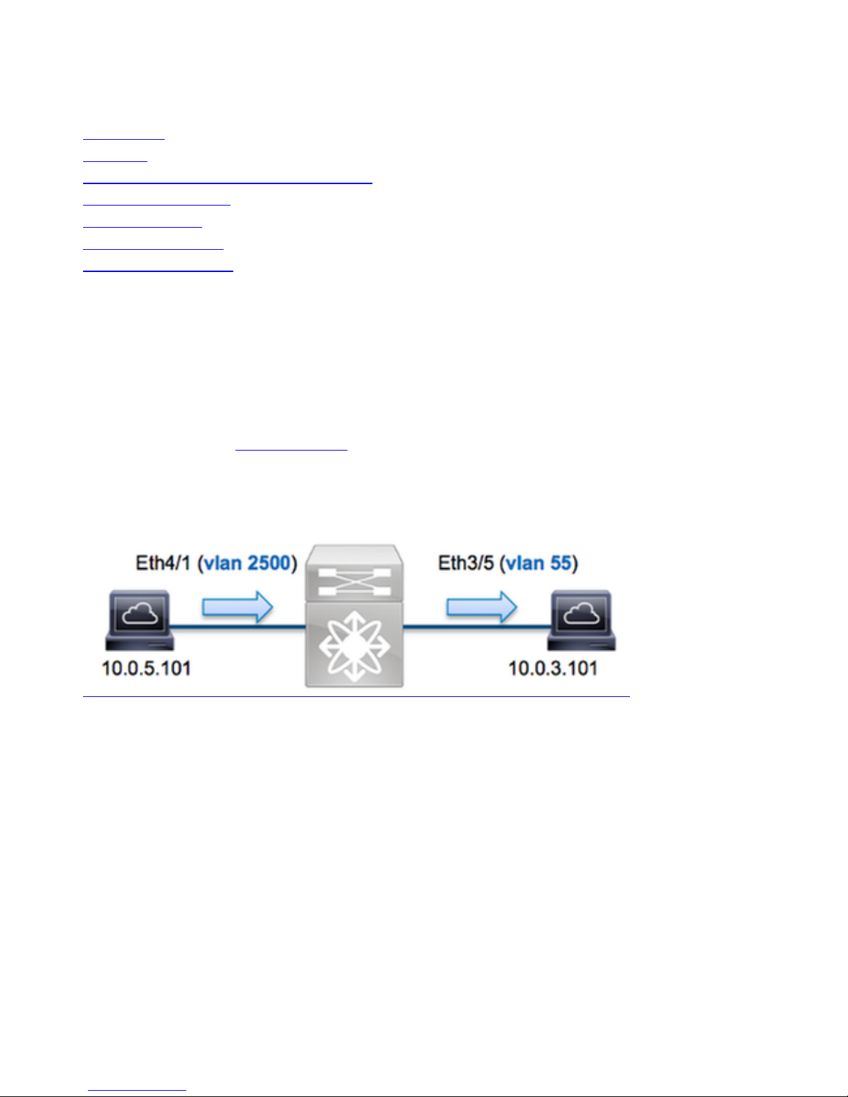
Topology
In this example, a host on VLAN 2500 (10.0.5.101), port Eth4/1 sends an Internet Control
Message Protocol (ICMP) request to a host on VLAN 55 (10.0.3.101), port Eth3/5. ELAM is used
in order to capture this single packet from 10.0.5.101 to 10.0.3.101. It is important to remember
that ELAM allows you to capture a single frame.
In order to perform an ELAM on the N7K, you must first connect to the appropriate module (this
requires the network-admin privilege):
N7700# attach module 4
Attaching to module 4 ...
module-4#
Determine the Ingress Forwarding Engine
Traffic is expected to ingress the switch on port Eth4/1. When you check the modules in the
system, you see that Module 4 is an M3 module. It is important to remember that the N7K is fullydistributed, and that the modules, not the supervisor, make the forwarding decisions for dataplane
Page 2

traffic.
N7700# show module
Mod Ports Module-Type Model Status
--- ----- ----------------------------------- ------------------ ---------1 12 100 Gbps Ethernet Module N77-F312CK-26 ok
3 48 1/10 Gbps Ethernet Module N77-M348XP-23L ok 4 24 10/40 Gbps Ethernet Module
N77-M324FQ-25L ok
5 0 Supervisor Module-2 N77-SUP2E active *
6 0 Supervisor Module-2 N77-SUP2E ha-standby
7 24 10/40 Gbps Ethernet Module N77-F324FQ-25 ok
Mod Sw Hw
--- --------------- -----1 7.3(0)DX(1) 1.1
3 7.3(0)DX(1) 1.1 4 7.3(0)DX(1) 1.0 5 7.3(0)DX(1) 1.2 6 7.3(0)DX(1) 1.2 7 7.3(0)DX(1) 1.0
For M-Series modules, perform the ELAM on the Layer 2 (L2) Forwarding Engine (FE) with
internal codename F4. Note that the L2 FE Data Bus (DBUS) contains the original header
information before the L2 and Layer 3 (L3) lookups, and the Result Bus (RBUS) contains the
results after both L3 and L2 lookups.
N7K M3 modules can use multiple FEs for each module, so you must determine the F4 ASIC that
is used for the FE on port Eth4/1. Enter this command in order to verify this:
module-4# show hardware internal dev-port-map
(some output omitted)
-------------------------------------------------------------- CARD_TYPE: 24 port 40G >Front
Panel ports:24 -------------------------------------------------------------- Device name Dev
role Abbr num_inst: -------------------------------------------------------------- > SLF L3
Driver DEV_LAYER_3_LOOKUP L3LKP 4 > SLF L2FWD driver DEV_LAYER_2_LOOKUP L2LKP 4
+-----------------------------------------------------------------------+
+----------------+++FRONT PANEL PORT TO ASIC INSTANCE MAP+++------------+
+-----------------------------------------------------------------------+
FP port | PHYS | MAC_0 | RWR_0 | L2LKP | L3LKP | QUEUE |SWICHF
1 0 0 0 0 0 0,1
2 0 0 0 0 0 0,1
3 0 0 0 0 0 0,1
In the output, you can see that port Eth4/1 is on F4 (L2LKP) instance 0. On the N77-M312CQ-26L
module, there are 6 F4 ASICs with 2 ports in each port group. On the N77-M324FQ-25L module,
there are 4 F4 ASICs with 6 ports in each port group. The N77-M348XP-23L module has 2 F4
ASICs with 12 ports in each port group.
Note: Just like F-series modules, M3 module ELAM syntax uses 0-based values. This is not
the case for M1 and M2 modules, which use 1-based values.
module-4# elam asic f4 instance 0
module-4(f4-elam)# layer2
module-4(f4-l2-elam)#
Configure the Trigger
The F4 ASIC supports ELAM triggers for IPv4, IPv6, and others. The ELAM trigger must align with
the frame type. If the frame is an IPv4 frame, then the trigger must also be IPv4. An IPv4 frame is
not captured with an other trigger. The same logic applies to IPv6.
With Nexus Operating Systems (NX-OS), you can use the question mark character in order to
separate the ELAM trigger:
module-4(f4-l2-elam)# trigger dbus ipv4 ingress if ?
Page 3

(some output omitted)
destination-index Destination-index
destination-ipv4-address Destination ipv4 address
destination-ipv4-mask Destination ipv4 mask
destination-mac-address Destination mac address
l4-protocol L4 protocol
source-index Source-index
source-ipv4-address Source ipv4 address
source-ipv4-mask Source ipv4 mask
source-mac-address Source mac address
For this example, the frame is captured according to the source and destination IPv4 addresses,
so only those values are specified.
F4 requires separate triggers for the DBUS and the RBUS.
Here is the DBUS trigger:
module-4(f4-l2-elam)# trigger dbus ipv4 ingress if source-ipv4-address
10.0.5.101 destination-ipv4-address 10.0.3.101
Here is the RBUS trigger:
module-4(f4-l2-elam)# trigger rbus ingress result if tr 1
Start the Capture
Now that the ingress FE is selected and you configured the trigger, you can start the capture:
module-4(f4-l2-elam)# start
In order to check the status of the ELAM, enter the status command:
module-4(f4-l2-elam)# status
ELAM Slot 4 instance 0: L2 DBUS/LBD Configuration: trigger dbus ipv4 ingress if
source-ipv4-address 10.0.5.101 destination-ipv4-address 10.0.3.101
L2 DBUS/LBD: Configured
ELAM Slot 4 instance 0: L2 RBUS Configuration: trigger rbus ingress result if tr 1
L2 RBUS: Configured
L2 BIS: Unconfigured
L2 BPL: Unconfigured
L2 EGR: Unconfigured
L2 PLI: Unconfigured
L2 PLE: Unconfigured
Once the frame that matches the trigger is received by the FE, the ELAM status shows as
Triggered:
module-4(f4-l2-elam)# status
ELAM Slot 4 instance 1: L2 DBUS/LBD Configuration: trigger dbus ipv4 ingress if
source-ipv4-address 10.0.5.101 destination-ipv4-address 10.0.3.101
L2 DBUS/LBD: Triggered
ELAM Slot 4 instance 1: L2 RBUS Configuration: trigger rbus ingress result if tr 1
L2 RBUS: Triggered
L2 BIS: Unconfigured
L2 BPL: Unconfigured
L2 EGR: Unconfigured
L2 PLI: Unconfigured
L2 PLE: Unconfigured 7
Interpret the Results
Page 4

In order to display the ELAM results, enter the show dbus and show rbus commands. If there is
a high volume of traffic that matches the same triggers, the DBUS and RBUS might trigger on
different frames. Therefore, it is important to check the internal sequence numbers on the DBUS
and RBUS data in order to ensure that they match:
module-4(f4-l2-elam)# show dbus | i seq
port-id : 0x0 sequence-number : 0x868
module-4(f4-l2-elam)# show rbus | i seq
de-bri-rslt-valid : 0x1 sequence-number : 0x868
Here is the excerpt from the ELAM data that is most relevant to this example (some output is
omitted):
module-4(f4-l2-elam)# show dbus
------------------------------------------------------------------- LBD IPV4
-------------------------------------------------------------------ttl : 0xff l3-packet-length : 0x54
destination-address: 10.0.3.101
source-address: 10.0.5.101
-------------------------------------------------------------------packet-length : 0x66 vlan : 0x9c4
segid-lsb : 0x0 source-index : 0xe05
destination-mac-address : 8c60.4f07.ac65
source-mac-address : 8c60.4fb7.3dc2
port-id : 0x0 sequence-number : 0x868
module-4(f4-l2-elam)# show rbus
------------------------------------------------------------------- L2 RBUS RSLT CAP DATA
-------------------------------------------------------------------de-bri-rslt-valid : 0x1 sequence-number : 0x868
vlan : 0x37 rbh : 0x65
cos : 0x0 destination-index : 0x9ed
With the DBUS data, you can verify that the frame is received on VLAN 2500 with a source MAC
address of 8c60.4fb6.3dc2 and a destination MAC address of 8c60.4f07.ac65. You can also see
that this is an IPv4 frame that is sourced from 10.0.5.101, and is destined to 10.0.3.101.
Tip: There are several other useful fields that are not included in this output, such as Type of
Service (TOS) value, IP flags, IP length, and L2 frame length.
In order to verify on which port the frame is received, enter the SRC_INDEX command (the source
Local Target Logic (LTL)). Enter this command in order to map an LTL to a port or group of ports
for the N7K:
N7700# show system internal pixm info ltl 0xe05
Member info
-----------------Type LTL
---------------------------------
PHY_PORT Eth4/1
FLOOD_W_FPOE 0xc031
The output shows that the SRC_INDEX of 0xe05 maps to port Eth4/1. This confirms that the
frame is received on port Eth4/1.
With the RBUS data, you can verify that the frame is routed to VLAN 55. Notice that the TTL starts
as 0xff in the DBUS data. Additionally, you can confirm the egress port from the DEST_INDEX
Page 5

(destination LTL):
N7K# show system internal pixm info ltl 0x9ed
Member info
-----------------Type LTL
---------------------------------
PHY_PORT Eth3/5
FLOOD_W_FPOE 0x8017
FLOOD_W_FPOE 0x8016
The output shows that the DEST_INDEX of 0x9ed maps to port Eth3/5. This confirms that the
frame is sent from port Eth3/5.
Additional Verification
In order verify how the switch allocates the LTL pool, enter the show system internal pixm info
ltl-region command. The output from this command is useful in order to understand the purpose
of an LTL if it is not matched to a physical port. A good example of this is a Drop LTL:
N7700# show system internal pixm info ltl 0xcad
0x0cad is Drop DI LTL
N7700# show system internal pixm info ltl-region
(some output omitted) =========================================================== PIXM VDC 1 LTL
MAP Version: 3 Description: LTL Map for Crossbow
=========================================================== LTL_TYPE SIZE START END
========================================================================
LIBLTLMAP_LTL_TYPE_PHY_PORT 3072 0x0 0xbff LIBLTLMAP_LTL_TYPE_SUP_ETH_INBAND 64 0xc00 0xc3f
LIBLTLMAP_LTL_TYPE_UCAST_VPC_VDC_SI 32 0xc40 0xc5f LIBLTLMAP_LTL_TYPE_EXCEPTION_SPAN 32 0xc60
0xc7f LIBLTLMAP_LTL_TYPE_UCAST_GENERIC 48 0xc80 0xcaf ------------------------------------------
------------------------- SUB-TYPE LTL ---------------------------------------------------------
---------- LIBLTLMAP_LTL_TYPE_UCAST_GENERIC_NOT_USED 0xcaf
LIBLTLMAP_LTL_TYPE_DROP_DI_WO_HW_BITSET 0xcae LIBLTLMAP_LTL_TYPE_DROP_DI
0xcad
LIBLTLMAP_LTL_TYPE_SUP_DIAG_SI_V5 0xcac
LIBLTLMAP_LTL_TYPE_RESERVED_ERSPAN_LTL 0xcab
------------------------------------------------------------------LIBLTLMAP_LTL_TYPE_LC_CPU 192 0xcb0 0xd6f
LIBLTLMAP_LTL_TYPE_UCAST_RESERVED 144 0xd70 0xdff
LIBLTLMAP_LTL_TYPE_PC 1536 0xe00 0x13ff
LIBLTLMAP_LTL_TYPE_DYNAMIC_UCAST 5120 0x1400 0x27ff
LIBLTLMAP_LTL_TYPE_MCAST_RESERVED 48 0x2800 0x282f
LIBLTLMAP_LTL_TYPE_DYNAMIC_MCAST 38848 0x2830 0xbfef
LIBLTLMAP_LTL_TYPE_SAC_FLOOD 16 0xbff0 0xbfff
LIBLTLMAP_LTL_TYPE_FLOOD_WITH_FPOE 16384 0xc000 0xffff
 Loading...