

Page 1
Installation
This chapter contains the following sections:
Installation Notes and Warnings for the Cisco UCS 5108 Server Chassis, page 1
•
Installing the Chassis, page 7
•
Repacking the Chassis, page 23
•
SFP+ Transceivers, page 23
•
Installation Notes and Warnings for the Cisco UCS 5108 Server Chassis
The following notes and warnings apply to all installation tasks:
Note
Warning
Warning
OL-20035-05 1
Before you install, operate, or service the system, see the Regulatory Compliance and Safety Information
for Cisco UCS for important safety information.
IMPORTANT SAFETY INSTRUCTIONS
This warning symbol means danger. You are in a situation that could cause bodily injury. Before you
work on any equipment, be aware of the hazards involved with electrical circuitry and be familiar with
standard practices for preventing accidents. Use the statement number provided at the end of each warning
to locate its translation in the translated safety warnings that accompanied this device. Statement 1071
SAVE THESE INSTRUCTIONS
This unit is intended for installation in restricted access areas. A restricted access area can be accessed
only through the use of a special tool, lock and key, or other means of security. Statement 1017
Cisco UCS 5108 Server Chassis Installation Guide
Page 2
Rack Requirements
Installation
Warning
Only trained and qualified personnel must be allowed to install, replace, or service this equipment.
Statement 1030
Rack Requirements
This section provides the requirements for installing in a standard open rack, assuming an external ambient
air temperature range of 50 to 95°F (10 to 35°C):
Note
Do not use racks that have obstructions. These obstructions could impair access to field-replaceable units
(FRUs).
The Cisco R Series Racks are an ideal choice. If other racks will be used, the rack must be of the following
type:
Standard 19-inch (48.3 cm) four-post EIA rack, a minimum of 39.4 inches (100 cm) deep, with mounting
•
rails that conform to English universal hole spacing per section 1 of ANSI/EIA-310-D-1992.
The mounting holes of the rails in the rack must be square (unless the optional round hole adapter kit is
•
used).
The tool-less rack-mount kit shipped with the chassis is required. The adjustable rack rails shipped with
•
each enclosure extend from 29 inches (73.66 cm) to 35 inches (88.9 cm)
• Front and rear doors—If your server rack includes closing front and rear doors, the doors must have 65
percent open perforated area evenly distributed from top to bottom to permit adequate airflow.
Caution
The rack must also meet the following requirements:
The minimum available vertical rack space per chassis must be six RU (rack units), equal to 10.5 inches
•
(26.7 cm).
Cable Management
To help with cable management, allow additional space in the rack above and below the chassis to make it
easier to route copper cables (plus up to eight copper cables per Cisco UCS 5108 server chassis) through the
rack.
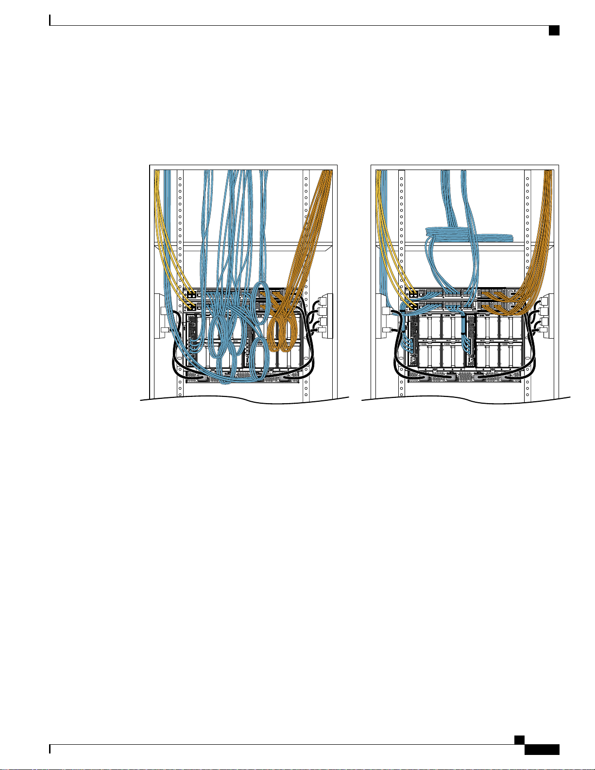
Cable management can be an important factor in preventing overheating issues. In the following figure, the
“before“ illustration shows cables blocking the rear of the chassis, and preventing the fans from exhausting
warm air from the chassis. This situation causes failed DIMMs in the blade servers, and seemingly random
Always use blanking panels to fill all remaining empty front panel U-spaces in the rack.
This arrangement ensures proper airflow. Using a rack without blanking panels results
in improper cooling that can lead to thermal damage.
Cisco UCS 5108 Server Chassis Installation Guide
2 OL-20035-05
Page 3
253898
Before
After
Installation
Airflow Considerations
server shutdowns when internal temperatures exceed specification. Use cable ties and other wiring practices
to keep the rear of the chassis unobstructed as shown in the “after“ illustration.
Figure 1: Cable Management
Airflow Considerations
Airflow through the chassis is from front to back. Air enters the chassis through the blade servers and power
supply grills at the front of the chassis and exits through the fan modules on the back of the chassis. To ensure
proper airflow, follow these guidelines:
Maintain ambient airflow throughout the data center to ensure normal operation.
•
Consider the heat dissipation of all equipment when determining air-conditioning requirements. Do not
•
allow the exhaust of one system to be the intake for another system.
When evaluating airflow requirements, take into consideration that the hot air generated by equipment
•
at the bottom of the rack can be drawn in the intake of the equipment above.
Make sure that the exhaust at the rear of the chassis is unobstructed for at least 24 in. (61 cm). This
•
includes obstruction due to messy cabling practices.
Some blade servers ship with internal shrouds that are placed over the DIMMs and CPUs. They are used
•
to channel airflow to where it is needed the most. If a shroud can be used a given model, it should be
used.
If an enclosed rack is used, the front door must be 65 percent perforated to ensure adequate airflow to
•
the servers.
Cisco UCS 5108 Server Chassis Installation Guide
OL-20035-05 3
Page 4
Moving Server Chassis
Moving Server Chassis
When lifting the chassis, be aware of its weight, and follow these guidelines:
Installation
Caution
Do not try to lift the chassis using the handles on the side. These handles are intended only for moving
and adjusting the chassis position.
• Never lift the chassis alone—Always use two people to lift the chassis. If available, use a scissor jack
or other lifting device designed for installing heavy equipment into data center racks.
Disconnect all power and external cables before lifting the chassis.
•
Remove all FEXes, power supplies, fans, and servers from the chassis before lifting.
•
Ensure that your footing is solid and the weight of the system is evenly distributed between your feet.
•
Lift the system slowly, keeping your back straight. Lift with your legs, not with your back. Bend at the
•
knees, not at the waist.
Do not remove the Power Distribution Unit (PDU) located at the back of the chassis.Caution
Installation Guidelines
When installing the chassis, follow these guidelines:
Plan your site configuration and prepare the site before installing the chassis. See Site Planning and
•
Maintenance Records for the recommended site planning tasks. Further detail is provided in the Cisco
UCS Site Preparation Guide.
Record the information listed in Site Planning and Maintenance Records as you install and configure
•
the chassis.
Ensure that there is adequate space around the chassis to allow for servicing the chassis and for airflow.
•
Ensure that the air-conditioning meets the heat dissipation requirements listed in Technical Specifications
•
Ensure that the cabinet or rack meets the requirements listed in Rack Requirements, on page 2.
•
Note
Ensure that the site power meets the power requirements listed in Technical Specifications. If available,
•
you can use an uninterruptible power supply (UPS) to protect against power failures.
Avoid UPS types that use ferroresonant technology. These UPS types can become unstable with systems
such as the Cisco UCS, which can have substantial current draw fluctuations due to fluctuating data
traffic patterns.
Cisco UCS 5108 Server Chassis Installation Guide
4 OL-20035-05
Jumper power cords are available for use in a rack. See Specifications for the Cisco
UCS 5108 Blade Server Chassis Power Supply Units.
Page 5
Installation
Ensure that circuits are sized according to local and national codes. For North America, the power supply
•
requires a 20 A circuit.
To prevent loss of input power, ensure that the total maximum loads on the circuits supplying power to
the chassis are within the current ratings for the wiring and breakers.
Use the following torque values when installing the chassis:
•
Required Equipment
Before you begin the installation, ensure that you have the following items:
Number 1 and number 2 Phillips-head screwdrivers with torque measuring capabilities
•
Tape measure and level
•
ESD wrist strap or other grounding device
•
10-32 screws: 20 in-lb
◦
Required Equipment
Antistatic mat or antistatic foam
•
Unpacking and Inspecting the Chassis
When handling chassis components, wear an ESD strap and handle modules by the carrier edges only.Caution
Keep the shipping container in case the chassis requires shipping in the future.Tip
Note
Step 1
Step 2
The chassis is thoroughly inspected before shipment. If any damage occurred during transportation or any
items are missing, contact your customer service representative immediately.
Procedure
Remove the chassis from its cardboard container. Save all packaging material.
Compare the shipment to the equipment list provided by your customer service representative and verify that
you have received the following items:
Any printed documentation
•
• Tool-less rack-mount kit (N20-CRMK2=)—mounting rails can be installed in a rack without the use of
tools. The optional round hole adapter kit (N20-CRMK2-RHA=) does require tools.
ESD wrist strap
•
Cables with connectors (including the N20-BKVM=, which is the KVM/local I/O console dongle)
•
Cisco UCS 5108 Server Chassis Installation Guide
OL-20035-05 5
Page 6
279771
1
2
3
Attaching the Round Hole Adapter Kit to the Rails (Optional)
Any optional items ordered
•
Installation
Step 3
Verify that all unused blade slots and power supply bays have blank covers.
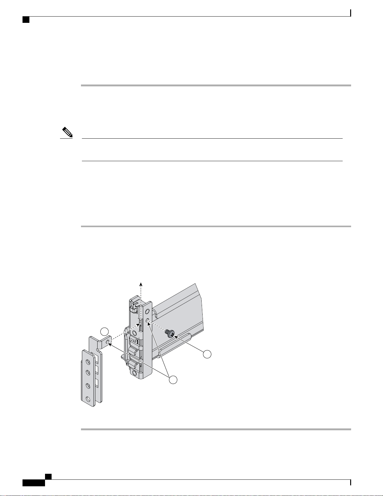
Attaching the Round Hole Adapter Kit to the Rails (Optional)
Note
Step 1
Step 2
Step 3
The chassis tool-less rails are designed for racks that have square mounting holes. You must use the round
hole adapters (N20-CRMK2-RHA=) to install the chassis in racks that have round mounting holes.
This round hole adapter kit allows you to adapt the rail kit (N20-CRMK2=) to install into rack (front and/or
rear) posts that use either threaded or non-threaded round holes. Four adapters in the kit are for adapting the
rail kit to install into rack posts with threaded round holes, and the other four adapters in the kit are for adapting
the rail kit to install into rack posts with non-threaded round holes. You can use a combination of adapters
based on the type of holes in the rack posts. Various sizes and lengths of screws are also included in the kit.
Procedure
Insert the adapter tab into the mounting rail as shown in callout 1.
Slide the adapter up to lock it into position as shown in callout 2.
Secure the adapter into place using the provided pan-head screw as shown in callout 3.
Figure 2: Attaching the Round Hole Adapter (Optional)
Step 4
Repeat steps 1to 3 for the other three adapters.
Cisco UCS 5108 Server Chassis Installation Guide
6 OL-20035-05
Page 7
Installation
Installing the Chassis
This section describes how to install the chassis. This two part process consists of installing the rails into the
rack and then installing the chassis into the rack and on to the rails.
Installing the Chassis
Caution
Caution
Never attempt to lift the chassis by using an installed module’s handle as a grip point. only use the handles
on the sides of the chassis.
If the rack has wheels, ensure that the brakes are engaged, the stabilizing pads are extended, or that the
rack is otherwise stabilized.
Table 1: Contents of the Cisco UCS 5108 Server Chassis Rack-Mount Kit (N20-CRMK2=)
Part DescriptionQuantity
Left tool-less rack mount rail1
Right tool-less rack mount rail1
10-32 X 0.75 Phillips round washer head screws6
10-32 X 0.125 cage nuts6
Table 2: Contents of the Cisco UCS 5108 Server Round Hole Adapter Kit (N20-CRMK2-RHA=)
Part DescriptionQuantity
Round hole adapters (threaded)4
Round hole adapters (un-threaded)4
Adapter securing screws4
Phillips head screws for securing the rails to the rack16
Warning
The plug-socket combination must be accessible at all times, because it serves as the main disconnecting
device. Statement 1019
Cisco UCS 5108 Server Chassis Installation Guide
OL-20035-05 7
Page 8
192517
Sl
i
de-adjust
192731
.250
.625
.625
.500
Installing the Rails
Installing the Rails
Procedure
Installation
Step 1
Step 2
Step 3
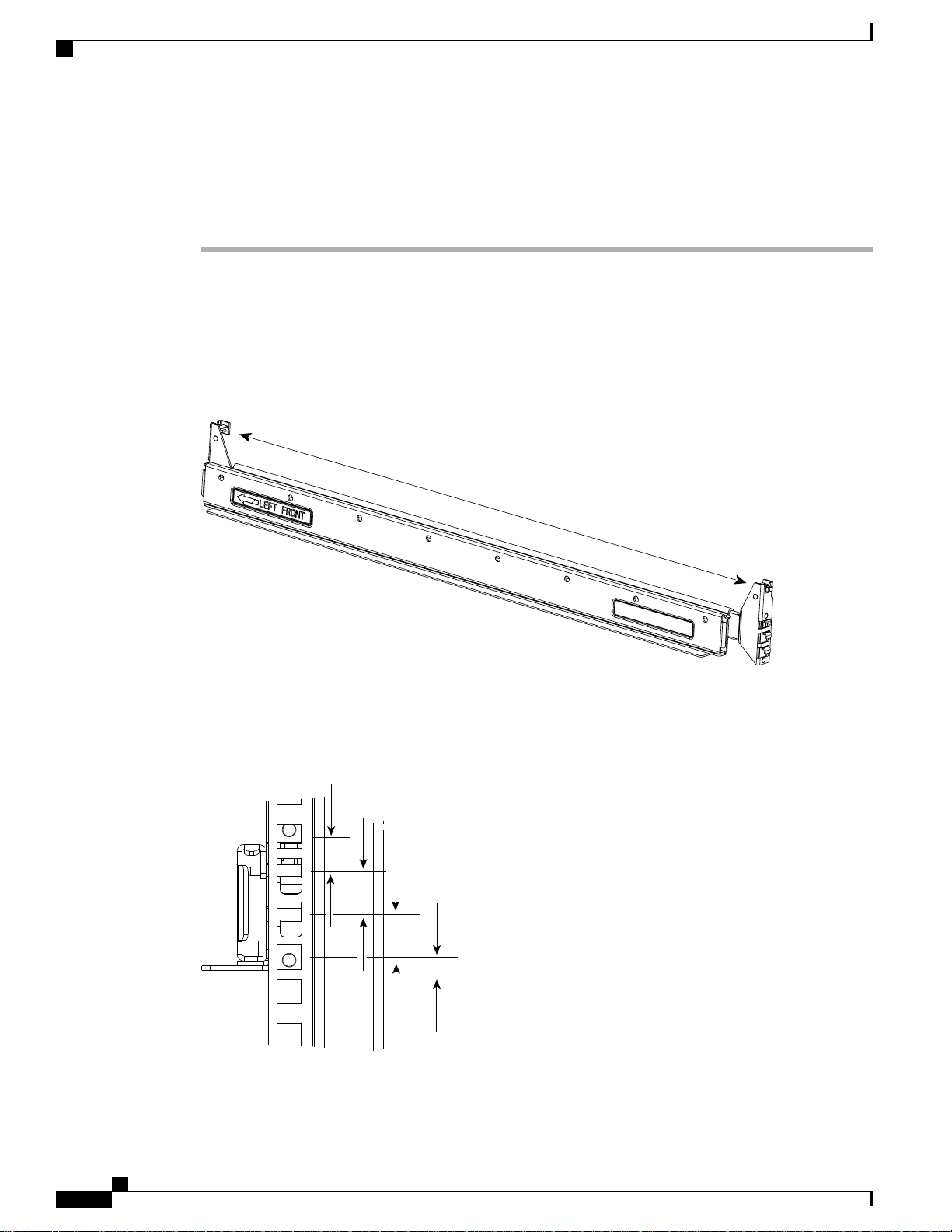
Remove the mounting template (Cisco 78-19093-01) from the accessory box. The template is designed to
show you the proper holes within which the rails and cage nuts should be placed. Once the rack holes line up
with the template, you should mark the holes so that their position is known after removing the template.
Adjust the length of the rail by sliding the ends of the rail back and forth until they match the depth of the
rack.
Figure 3: Adjusting the Tool-less Rack Mount Rail
Place the two hooks at each end of the rail into the first two holes at a rack unit boundary.
Figure 4: Hole Spacing for the Tool-less Rails in Relationship to a Rack Unit
Cisco UCS 5108 Server Chassis Installation Guide
8 OL-20035-05
Page 9

192518
Installation
Installing the Rails
The following figure shows a rail mounted into a rack in the proper position with respect to a rack-unit
boundary. Measurements are in inches between the centers of the holes.
Figure 5: Installing Tool-less Chassis Support Rails into the Rack
Step 4
Step 5
Step 6
Step 7
Press down firmly on the rail until the hooks seat firmly and securely into the holes, and the spring clip latches
into place.
Follow the same procedure to install the other rack rail.
Use a tape measure and level to verify that the rack rails are horizontal and at the same height.
Insert the cage nuts on to the rack in the needed square holes as shown below. When the rails are installed on
a rack unit boundary, the first two cage nuts are installed into the seventh holes above the rails’ horizontal
OL-20035-05 9
Cisco UCS 5108 Server Chassis Installation Guide
Page 10

192824
4
5
7
Lower rack unit
reference boundry
Installing the Rails
Installation
plates. The next two cage nuts are installed into the fifth holes above the first cage nut. Finally, the two cage
nuts are installed into the fourth holes above the second cage nuts.
Figure 6: Placement of Rails and Cage Nuts with Respect to the Rack Unit Boundary
Figure 7: Proper Placement for the Rails and Cage Nuts
Cisco UCS 5108 Server Chassis Installation Guide
10 OL-20035-05
Page 11

.250
.625
.625
.500
.
Left rail
Right rail
Cage nuts
192730
Installation
Installing the Round Hole Adapter Kit
Step 8
Remove all power supplies, fan assemblies, server blades, and fabric extenders to lighten the chassis. Even
with devices removed, the chassis weighs 90 lbs (40.83 kg).
Installing the Round Hole Adapter Kit
Before installing the chassis in a round hole rack, prepare the rails by adding the adapter kit according to the
instructions in Attaching the Round Hole Adapter Kit to the Rails (Optional), on page 6.
Cisco UCS 5108 Server Chassis Installation Guide
OL-20035-05 11
Page 12

279772
Installing the Round Hole Adapter Kit
Procedure
Installation
Step 1
Step 2
Step 3
Step 4
Remove the mounting template (Cisco 78-19093-01) from the accessory box. The template is designed to
show you the proper holes within which the rails and cage nuts should be placed. Once the rack holes line up
with the template, you should mark the holes so that their position is known after removing the template.
Adjust the length of the rail by sliding the ends of the rail back and forth until they match the depth of the
rack.
Place the adapters and rails even with a rack boundary at each end of the rail.
Secure the rail to the rack with the provided pan head screws as shown below.
Figure 8: Attaching the Mounting Brackets to a Round Hole Rack
Cisco UCS 5108 Server Chassis Installation Guide
12 OL-20035-05
Page 13

279774
Installation
Installing the Round Hole Adapter Kit
Step 5
Follow the same procedure to install the other rack rail as shown below.
Figure 9: Round Hole Adapter and Rails Installed in a Rack
Step 6
Step 7
Use a tape measure and level to verify that both rack rails are horizontal and at the same height.
Remove all power supplies, fan assemblies, server blades, and I/O modules to lighten the chassis. Even with
devices removed, the chassis weighs 90 lbs (40.83 kg).
Cisco UCS 5108 Server Chassis Installation Guide
OL-20035-05 13
Page 14

192518
Weight bearing surface.
Chassis should be riding
on this surface.
NON-WEIGHT BEARING SURFACE-
CHASSIS SHOULD NOT BE RIDING
ON THIS SURFACE
Inserting the Chassis into the Rack
Inserting the Chassis into the Rack
Procedure
Installation
Step 1
With the help of another person (or special lifting equipment), lift the chassis and place it on the mounting
rail as shown.
Figure 10: Mounting Rail Weight Distribution (Square Hole Mount Shown)
Caution
The mounting rails may come loose and cause the chassis to fall if the weight is resting on the
wrong surface. Make sure that the bottom of the chassis is resting on the correct rail surface.
14 OL-20035-05
Cisco UCS 5108 Server Chassis Installation Guide
Page 15

192519
Installation
Inserting the Chassis into the Rack
Step 2
Step 3
Slide the chassis into the rack until the front flange is flat against the cage nuts. (Cage nuts are not needed in
round hole racks.)
Using the six Phillips round washer head screws and the cage nuts (used in square hole installations), secure
the chassis by its flanges to the rack as shown.
Figure 11: Securing the Chassis Into the Rack
Step 4
Step 5
Replace all servers, fans, and power supplies back into their respective chassis slots.
To power up the chassis, connect the appropriate AC power cables to the inlet connector corresponding to
each installed power supply, and then connect the other end of the cables to the power source. For a DC
installation, see Connecting a DC Power Supply, on page 16.To determine the number of power supplies
needed for a given configuration, use the Cisco UCS Power Calculator tool.
Cisco UCS 5108 Server Chassis Installation Guide
OL-20035-05 15
Page 16

PS 1
PS 2
PS 3
PS 4
Server Slot 1
Server Slot 2
Server Slot 3
Server Slot 5
Server Slot 7
Server Slot 4
Server Slot 6
Server Slot 8
Front
Fan 1
Fan 2
I/O Module Slot 1
I/O Module Slot 2
Connector
PS 4
Connector
PS 3
Connector
PS 2
Connector
PS 1
Fan 6
Fan 5
Fan 4
Fan 3
Fan 8
Fan 7
Rear
279770
Connecting a DC Power Supply
Installation
Step 6
Note
Both grids in a power redundant system should have the same number of power supplies. If your system is configured for grid redundancy,
slots 1 and 2 are assigned to grid 1 and slots 3 and 4 are assigned to grid 2. If only two power supplies (PS) are in a redundant- mode
chassis, they should be in slots 1 and 3. Slot and cord connection numbering is shown below.
Figure 12: Power Supply Bay and Connector Numbering
Connect the server chassis to the fabric interconnect as described in Proper FEX and Fabric Interconnect Port
Connectivity, on page 20.
Connecting a DC Power Supply
This section describes how to connect power to the rear PDU terminals on the DC version chassis
(UCSB-5108-DC) corresponding to a UCS 5108 DC power supply (UCSB-PSU-2500DC48).
Required Tools
You must have the following tools to perform this procedure:
A Phillips screwdriver
•
A 10-mm wrench or socket
•
Connectors and wire for the DC circuit or circuits
•
DC Power Installation Procedure
Warning
When stranded wiring is required, use approved wiring terminations, such as closed-loop or spade-type
with upturned lugs. These terminations should be the appropriate size for the wires and should clamp both
the insulation and conductor. Statement 1002
Cisco UCS 5108 Server Chassis Installation Guide
16 OL-20035-05
Page 17

Installation
Connecting a DC Power Supply
Warning
Warning
Warning
Warning
Before performing any of the following procedures, ensure that power is removed from the DC circuit.
Statement 1003
A readily accessible two-poled disconnect device must be incorporated in the fixed wiring. Statement
1022
Use copper conductors only. Statement 1025Warning
This product requires short-circuit (overcurrent) protection, to be provided as part of the building installation.
Install only in accordance with national and local wiring regulations. Statement 1045
When installing or replacing the unit, the ground connection must always be made first and disconnected
last. Statement 1046
Installation of the equipment must comply with local and national electrical codes. Statement 1074Warning
Warning
Step 1
Step 2
Step 3
Step 4
Step 5
Step 6
Hazardous voltage or energy may be present on DC power terminals. Always replace cover when terminals
are not in service. Be sure uninsulated conductors are not accessible when cover is in place. Statement
1075
Procedure
Install the DC power supply in the chassis, making note of the bay number, so you are sure to connect the
wiring to the appropriate terminals on the DC PDU at the chassis rear.
Verify that power is off to the DC circuit or circuits on the power supply that you are installing.
Ensure that all site power and grounding requirements have been met.
Remove the plastic cover from the DC terminals by squeezing the flanges at the top and bottom of the cover.
Connect the ground wires to the power supply terminal block, shown as a green wire below. Only one ground
connection is required, though there may be up to four DC connections.
Connect the DC-input wires to the power supply terminal block. The proper wiring sequence is positive to
positive (red wire), and negative to negative (black wire). The figure below shows a connection to terminal
1.
Cisco UCS 5108 Server Chassis Installation Guide
OL-20035-05 17
Page 18

237204
Connecting a DC Power Supply
Installation
Note
The positive and negative wires can be installed pointing either to the right or to the left as long as
the terminal cover is used. The figure below shows them pointed to the right. Panduit LCD4-14A-L
connectors may be used for the supply and return wires, and Panduit LCD4-14AF-L or equivalent
connectors may be used for the 90-degree ground lug wire. Both connections have double lugs with
.25 inch holes measuring .625 inches from center to center.
Figure 13: Connecting DC Power to the Chassis (shows DC PDU only, Chassis is Omitted)
Cisco UCS 5108 Server Chassis Installation Guide
18 OL-20035-05
Page 19

1 3 5 7 9 11 13 15 17 19 21 23 25 27 29 31
26 28 30 3218 20 22 2410 12 14 162 4 6 8
1 3 5 7 9 11 13 15
10 12 14 162 4 6 8
1 2 3 4 5 6
330345
Installation
Cabling Considerations for Fabric Port Channels
Step 7
Replace the terminal cover as shown. This cover should always be in place when power is applied to the
terminals.
Step 8
Step 9
Connect the other end of the power wires to a DC-power input source.
Set the DC disconnect switch in the circuit to ON.
Caution
In a system with multiple power supplies, connect each power supply to a separate DC power
source. In the event of a power source failure, if the second source is still available, it can maintain
system operation.
Step 10
Step 11
Verify power supply operation by checking the power supply's front-panel LEDs. You should see the following:
The LED labeled INPUT OK is green.
•
The LED labeled OUTPUT FAIL is not lit.
•
Check the power supply and system status from the UCS console by entering the show system command or
the show power command, do using the GUI. For more information on these commands, refer to the command
reference for your software.
Cabling Considerations for Fabric Port Channels
When you configure the links between the Cisco UCS 2200 Series FEX and a Cisco UCS 6200 series fabric
interconnect in fabric port channel mode, the available VIF namespace on the adapter varies depending on
where the FEX uplinks are connected to the fabric interconnect ports.
Inside the 6248 fabric interconnect there are six sets of eight contiguous ports, with each set of ports managed
by a single chip. When uplinks are connected such that all of the uplinks from an FEX are connected to a set
of ports managed by a single chip, Cisco UCS Manager maximizes the number of VIFs used in service profiles
deployed on the blades in the chassis. If uplink connections from an IOM are distributed across ports managed
by separate chips, the VIF count is decreased.
Figure 14: Port Groups for Fabric Port Channels
Caution
Adding a second link to a fabric port channel port group is disruptive and will automatically increase the
available amount of VIF namespace from 63 to 118. Adding further links is not disruptive and the VIF
namespace stays at 118.
OL-20035-05 19
Cisco UCS 5108 Server Chassis Installation Guide
Page 20

Proper FEX and Fabric Interconnect Port Connectivity
Installation
Caution
Linking a chassis to two fabric port channel port groups is disruptive and does not affect the VIF namespace
unless it is manually acknowledged. The VIF namespace is then automatically set to the smaller size fabric
port channel port group usage (either 63 or 118 VIFs) of the two groups.
For high availability cluster mode applications, symmetric cabling configurations are strongly recommended.
If the cabling is asymmetric, the maximum number of VIFs available is the smaller of the two cabling
configurations.
For more information on the maximum number of VIFs for your Cisco UCS environment, see the configuration
limits document for your hardware and software configuration.
Proper FEX and Fabric Interconnect Port Connectivity
Note
The following illustrations are for example only; you do not need to skip available ports to provide future
expansion room. See the UCS Manager configuration guide for FI port configuration considerations and
limitations.
Observe the following guidelines:
When you connect the server chassis to the fabric interconnect, do not connect the FEXes to the fabric
•
interconnect’s expansion modules. While similar in appearance to the other ports on the fabric interconnect,
the expansion modules are never used for direct chassis connections. They are typically used for SAN
connectivity or network uplink.
All ports of a FEX must be connected to only one fabric interconnect. You must connect each fabric
•
interconnect to the chassis through its own FEX.
If you need to connect to a second fabric interconnect, do the following:
•
The chassis must have a second FEX installed.
◦
All ports of the second FEX must be connected to the second fabric interconnect only because the
◦
FEX is a fabric extender, which can only be connected to a single switch, or in this case, a fabric
interconnect.
Cisco UCS 5108 Server Chassis Installation Guide
20 OL-20035-05
Page 21

I/O Module Slot1 I/OModule Slot 2I/O Module Slot 1 I/OModule Slot 2
Chassis 1 rear
Port 1
Port 2
Port 3
Port 4
Port 1
Port 2
Port 3
Port 4
1 3 5 7 9 11 13 15 17 19 21 23 25 27 29 31
26 28 30 3218 20 22 2410 12 14 162 4 6 8
1 3 5 7 9 11 13 15
10 12 14 162 4 6 8
1 3 5 7 9 11 13 15 17 19 21 23 25 27 29 31
26 28 30 3218 20 22 2410 12 14 162 4 6 8
1 3 5 7 9 11 13 15
10 12 14 162 4 6 8
Fabric Interconnect A Rear
Fabric Interconnect B Rear
192748
Installation
Proper FEX and Fabric Interconnect Port Connectivity
The following figure shows an invalid connection from a FEX to two separate fabric interconnects.
Figure 15: Invalid Connection for the Server Chassis and two Cisco UCS 6120XP Fabric Interconnects
Both fabric interconnects should be wired identically: if port 1 on FEX 1 for a chassis goes to FI-A
◦
port 5, then port 1 on FEX 2 goes to FI-B port 5.
The following figure shows valid connections from FEXes in two chassis to two separate fabric
interconnects. When you connect the server chassis to the fabric interconnect do not connect the
FEXes to the fabric interconnect's expansion modules. While similar in appearance to the other
Cisco UCS 5108 Server Chassis Installation Guide
OL-20035-05 21
Page 22

I/O Module Slot 1 I/OModule Slot 2I/O Module Slot 1 I/OModule Slot 2
Chassis 1 rear
Port 1
Port 2
Port 3
Port 4
Port 1
Port 2
Port 3
Port 4
1 3 5 7 9 11 13 15 17 19 21 23 25 27 29 31
26 28 30 3218 20 22 2410 12 14 162 4 6 8
1 3 5 7 9 11 13 15
10 12 14 162 4 6 8
1 3 5 7 9 11 13 15 17 19 21 23 25 27 29 31
26 28 30 3218 20 22 2410 12 14 162 4 6 8
1 3 5 7 9 11 13 15
10 12 14 162 4 6 8
Fabric Interconnect A Rear
Fabric Interconnect B Rear
I/O Module Slot 1 I/OModule Slot 2I/O Module Slot 1 I/OModule Slot 2
Chassis 2 rear
Port 1
Port 2
Port 3
Port 4
Port 1
Port 2
Port 3
Port 4
192749
Removing the Chassis from a Rack
Installation
ports on the fabric interconnect, the expansion modules are never used for direct chassis connections,
they are used for uplink or SAN connections.
Figure 16: Proper Connection for the Server Chassis and two Cisco UCS 6120XP Fabric Interconnects
Removing the Chassis from a Rack
If you plan to remove a chassis from a UCS system and then from a rack you should first:
1
Use Cisco UCS Manager to shut down the OS on all blade servers in the chassis. Graceful shutdown of a
blade server is discussed in the “System Management“ section, “Managing Blade Servers” chapter of the
Cisco UCS Manager configuration guide for your software release. The related CLI commands are as
follows:
UCS-A# scope org
UCS-A /org # scope service-profile service-profile-name
Cisco UCS 5108 Server Chassis Installation Guide
UCS-A /org/service-profile # power down
22 OL-20035-05
Page 23

Installation
Repacking the Chassis
2
Disable the Smart Call Home feature, as mentioned in the “System Monitoring” section, “Configuring Call
Home” chapter of the Cisco UCS Manager configuration guide for your software release. The related CLI
commands are:
UCS-A# scope monitoring
UCS-A /monitoring # scope callhome
UCS-A /monitoring/callhome # disable
3
Decommission the chassis as described in the “System Management“ section, “Managing the Chassis“
chapter of the UCS Manager configuration guide for your software release. The related CLI command is
decommission-chassis chassis-num.
Procedure
Step 1
Step 2
Step 3
Step 4
Step 5
Step 6
Disconnect the power cords and networking cables from the chassis.
Remove all modules and blades from the chassis to lighten its weight.
Remove the screws holding the front rack-mount flange to the rack.
With two people holding the chassis, make sure that its weight is fully supported.
Gently slide the chassis off the rails, and out of the rack.
Replace the modules and blades in the server chassis.
Repacking the Chassis
If you need to repack the chassis, remove it from the rack by reversing the steps in the Removing the Chassis
from a Rack, on page 22 section, and then pack it for shipment. If possible, use the original packing materials
and container to pack the chassis. If you are returning the chassis to Cisco, contact your Cisco customer service
representative to arrange for return shipment to Cisco.
SFP+ Transceivers
Each FEX within the chassis supports Small Form-Factor Pluggable (SFP+) copper or optical transceivers.
Each transceiver runs at 10 Gb.
SFP+ Twinax Copper Transceivers
The FEX also supports Twinax copper transceivers. The enhanced SFP+ 10-Gb Ethernet transceiver is a
bidirectional device with a transmitter and receiver in the same physical package. It has a 20-pin connector
on the electrical interface.
Table 3: SFP+ 10 Gb Ethernet Transceiver
DescriptionModel
SFP-H10GB-CU1M
OL-20035-05 23
10-Gb Ethernet—copper SFP+ (1 m, 3.28 ft.)
Cisco UCS 5108 Server Chassis Installation Guide
Page 24

187492
Optical SFP+ Transceivers
Installation
DescriptionModel
SFP-H10GB-CU3M
SFP-H10GB-CU5M
SFP-H10GB-ACU7M
SFP-H10GB-ACU10M
10-Gb Ethernet—copper SFP+ (3 m, 9.84 ft.)
10-Gb Ethernet—copper SFP+ (5 m, 16.4 ft.)
10-Gb Ethernet—copper SFP+ (7 m, 22.9 ft.)
10-Gb Ethernet—copper SFP+ (10 m, 32.8 ft.)
The figure below shows the SFP-H10GB-CU5M transceiver. The rubber loop is used for removing the SFP+
from its port on the I/O module.
Figure 17: SFP+ 10 Gb Twinax Copper Transceiver
Optical SFP+ Transceivers
If distances greater than 10 meters (33 feet) must be spanned, the FEX also supports the substitution of the
copper SFP+ by optical SFP+ transceivers. The SFP+ 10-Gb Ethernet optical transceiver is a bidirectional
device with a transmitter and receiver in the same physical package. It has a duplex LC connector on the
optical interface.
DescriptionModel
SFP-10G-SR
SFP-10G-LR
1
While the SFP-10G-LR is supported by both the fabric interconnect and I/O module, the maximum distance will introduce latency issues that will affect overall
performance.
1
Documentation for SFP+ 10-Gb Ethernet optical transceivers is at
http://www.cisco.com/en/US/docs/interfaces_modules/transceiver_modules/installation/note/78_15160.html
Cisco UCS 5108 Server Chassis Installation Guide
24 OL-20035-05
Short–range optical SFP+ (up to 300 m/ 984 feet)
Long–range optical SFP+ (up to 10 km/6.2 miles)
Page 25

192627
192666
Installation
Replacing a Copper Twinax SFP+ Transceiver with an Optical SFP+ Transceiver
Replacing a Copper Twinax SFP+ Transceiver with an Optical SFP+ Transceiver
Procedure
Step 1
Step 2
Step 3
Remove the copper Twinax SFP+ from the FEX port by pulling gently on the rubber loop. The cable and
SFP+ transceiver come out as a single unit, leaving the FEX port empty.
Figure 18: Removing a Twinax Copper SFP+ Transceiver
Insert the optical SFP+ transceiver into the FEX port. Make sure that it clicks firmly into place.
Plug the fiber-optic cable into the optical SFP+ transceiver.
Figure 19: Replacing a Copper SFP+ Transceiver with an Optical SFP+ Transceiver
OL-20035-05 25
Cisco UCS 5108 Server Chassis Installation Guide
Page 26

Replacing a Copper Twinax SFP+ Transceiver with an Optical SFP+ Transceiver
Installation
Cisco UCS 5108 Server Chassis Installation Guide
26 OL-20035-05
 Loading...