

Page 1

Cisco ME 3600X-24CX Switch Getting Started
Guide
• About this Guide, page 2
• Box Contents, page 2
• Initial Setup, page 3
• Managing the Switch through the CLI, page 6
• Installing the Switch, page 6
• Connecting to the Switch Ports, page 10
• Troubleshooting, page 11
• Obtaining Documentation and Submitting a Service Request, page 12
Americas Headquarters:
Cisco Systems, Inc., 170 West Tasman Drive, San Jose, CA 95134-1706 USA
Page 2

About this Guide
About this Guide
This guide provides instructions on how to install and configure your Cisco Metro Ethernet (ME) 3800X
and ME 3600X switch. Also covered are switch management options, basic rack-mounting procedures,
port and module connections, and troubleshooting help.
For more installation and configuration information, see the Cisco ME 3800X and ME 3600X switch
documentation on Cisco.com. For system requirements, important notes, limitations, open and resolved
bugs, and last-minute documentation updates, see the release notes, also on Cisco.com.
When you use the online publications, refer to the documents that match the Cisco IOS software version
that is running on the switch. Look on the switch rear panel to locate the software version or enter the
show version command from the CLI.
For translations of safety warnings that appear in this publication, review the warnings in the Regulatory
Compliance and Safety Information for the Cisco ME 3600X-24CX Switch on Cisco.com.
Box Contents
Documentation
Product
and Compliance
10
2
6
333304
1
3
7
4
8
5
9
1 Cisco ME 3600X-2CX switch 6 Two 19-inch mounting brackets
2 Product documentation and compliance document 7 Cable guide and screw
3 AC power cord 8 Four number-12 pan head screws
4 Power cord bail and bushing 9 Four number-8 Phillips truss-head screws
5 Ground lug 10 Eight number-8 Phillips flat-head screws
Note Verify that you have received these items. If any item is missing or damaged, contact your Cisco
representative or reseller for instructions.
Cisco ME 3600X-24CX Switch Getting Started Guide
2
OL-27508-01
Page 3

Initial Setup
333305
Initial Setup
You need this equipment:
• PC
• Straight-through or crossover Category 5 Ethernet cable
Step 1
Step 2
Obtain this information from your network administrator before you start the setup program:
• Switch IP address
• Subnet mask (IP netmask)
• Default gateway (router)
• Enable secret password
• Enable password
• Telnet password
Connect the adapter cable to the console connector on the
switch front panel. Connect the other end of the cable to the
Ethernet port on your DHCP-enabled PC.
You must supply the console cable if you did not order one with
your switch.
Step 3
Step 4
Step 5
OL-27508-01
Start a terminal-emulation application such as Hyperterminal or ProcommPlus.
Configure the baud rate and character format of the PC or
terminal to match these console port default characteristics.
• 9600 baud
• 8 data bits
• 1 stop bit
• No parity
• None (flow control)
Power the switch.
AC power switches: Plug the AC power cord into the switch power supply and into a grounded AC outlet. Set the
power supply switch to ON.
DC power switches: See the wiring instructions in the hardware installation guide on Cisco.com.
Cisco ME 3600X-24CX Switch Getting Started Guide
3
Page 4

Initial Setup
Step 6
Approximately 30 seconds after the switch powers on, it begins the power-on self-test (POST), which can take up
to 5 minutes to complete.
During POST, the System (SYST) LED blinks green.
When POST is complete, the SYTEM LED is green.
Troubleshooting:
If the SYST LED blinks green, does not turn green, or turns amber, contact your Cisco representative or reseller.
The switch failed POST.
Step 7
Press Return or Enter at the prompt.
Completing the Initial Configuration
Follow these steps to complete the setup program and to create the initial switch configuration.
Step 1
Enter Ye s at these prompts:
Would you like to terminate autoinstall? [yes/no]: yes
Would you like to enter the initial configuration dialog? [yes/no]: yes
At any point you may enter a question mark '?' for help.
Use ctrl-c to abort configuration dialog at any prompt.
Default settings are in square brackets '[]'.
Press RETURN to get started!
Step 2
Step 3
Step 4
Step 5
Basic management setup configures only enough connectivity
for management of the system, extended setup will ask you
to configure each interface on the system.
Would you like to enter basic management setup? [yes/no]: yes
Enter a hostname for the switch, and press Return.
The hostname is limited to 20 characters. Do not use -n, where n is a number, as the last character in a hostname
for any switch.
Enter host name [Switch]: host_name
Enter an enable secret password, and press Return.
The password must be different from the enable secret password and can be from 1 to 25 alphanumeric characters,
can start with a number, is case sensitive, allows spaces, but ignores leading spaces. The secret password is
encrypted, and the enable password is in plain text.
Enter enable secret: secret_password
Enter an enable password, and press Return.
Enter enable password: enable_password
Enter a virtual terminal (Telnet) password, and press Return.
The password can be from 1 to 25 alphanumeric characters, is case sensitive, allows spaces, but ignores leading
spaces.
Enter virtual terminal password: terminal-password
Cisco ME 3600X-24CX Switch Getting Started Guide
4
OL-27508-01
Page 5

Initial Setup
Step 6
Step 7
Step 8
Step 9
(Optional) Configure Simple Network Management Protocol (SNMP) by responding to the prompts. You can also
configure SNMP later through the CLI. To configure SNMP later, enter no.
Configure SNMP Network Management? [no]: no
At the prompt, enter either FastEthernet0 or the VLAN name (usually VLAN1) as the interface connected to the
management network, and press Return.
Enter interface name used to connect to the
management network from the above interface summary: FastEthernet0
Enter Ye s after the prompt, and then enter the
switch IP address and subnet mask. Press
Return.
The IP address and subnet mask shown to the
right are examples.
Enter N when the prompt asks if you want to
enable the switch as a cluster command switch.
This switch will be a standalone switch that
does not support clustering.
Would you like to enable as a cluster
command switch? [yes/no]: no
The switch displays its initial configuration, as
shown on the right.
Configuring interface vlan1:
Configure IP on this interface? [yes]: yes
IP address for this interface: 10.4.120.106
Subnet mask for this interface [255.0.0.0]: 255.0.0.0
The following configuration command script was created:
hostname switch1
enable secret 5 $1$Ulq8$DlA/OiaEbl90WcBPd9cOn1
enable password enable_password
line vty 0 15
password terminal-password
no snmp-server
!
no ip routing
!
interface Vlan1
no shutdown
ip address 10.4.120.106 255.0.0.0
!
interface FastEthernet0/1
!
interface FastEthernet0/2
Step 10
OL-27508-01
...<output abbreviated>
interface FastEthernet1/0/3
!
interface GigabitEthernet0/1
!
interface GigabitEthernet0/2
!
end
These choices appear:
[0] Go to the IOS command prompt without saving this config.
[1] Return back to the setup without saving this config.
[2] Save this configuration to nvram and exit.
If you want to save the configuration and use it the next time the switch reboots, save it in
NVRAM by selecting option 2.
Enter your selection [2]:2
Make your selection, and press Return.
Cisco ME 3600X-24CX Switch Getting Started Guide
5
Page 6

Managing the Switch through the CLI
Step 11
Step 12
Disconnect the switch from the PC, and install the switch in your network. See the “Installing the Switch” section
on page 6.
See the “Managing the Switch through the CLI” section on page 6 for information about configuring and managing
the switch.
Note If you need to rerun the initial configuration dialog, see the “Resetting the Switch to the Default
Settings” section on page 12.
Managing the Switch through the CLI
After you install the switch in your network, you can enter Cisco IOS commands and parameters through
the CLI. Access the CLI either by connecting your PC directly to the switch console port or through a
Telnet session from a remote PC or workstation.
Other Management Options
You can use SNMP management applications such as CiscoWorks Small Network Management Solution
(SNMS) and HP OpenView to configure and manage the switch. You also can manage it from an
SNMP-compatible workstation that is running platforms such as HP OpenView or SunNet Manager.
The Cisco IE2100 Series Configuration Registrar is a network management device that works with
embedded CNS agents in the switch software. You can use IE2100 to automate initial configurations and
configuration updates on the switch.
See the “Accessing Help Online” section on page 12 for a list of supporting documentation.
Installing the Switch
This section covers 19-inch rack-mounting. For alternate mounting procedures, see the Cisco ME 3800X
and ME 3600X Switch Hardware Installation Guide on Cisco.com.
Equipment That You Supply
You need to supply a number-2 Phillips screwdriver to rack-mount the switch.
Before You Begin
When you determine where to install the switch, verify that these guidelines are met:
• Airflow around the switch and through the vents is unrestricted.
• Clearance to the switch front and rear panels meets these conditions:
–
You can easily see the System, MGMT, Alarm, port, and power-supply LEDS.
–
You have sufficient access to ports for cabling.
Cisco ME 3600X-24CX Switch Getting Started Guide
6
OL-27508-01
Page 7

• Cabling is away from sources of electrical noise, such as radios, power lines, and fluorescent
• For 10/100 or 10/100/1000 ports, the cable length from a switch to an attached device cannot exceed
• For cable lengths for small form-factor pluggable (SFP) modules, see the documentation that
• For cable lengths for XFP modules, see documentation that shipped with the module.
• Temperature around the switch does not exceed 122°F (50°C).
• Humidity around the switch does not exceed 95 percent.
• Altitude at the installation site is not greater than 10,000 feet.
Safety Warnings
Translations of these warning statements appear in the Regulatory Compliance and Safety Information
for the Cisco ME 3600X-24CX Switch document.
–
The AC power cord can reach from the power outlet to the front-panel connector.
lighting fixtures.
328 feet (100 meters).
shipped with the module.
Installing the Switch
Warning
Warning
Warning
Before working on equipment that is connected to power lines, remove jewelry (including rings,
necklaces, and watches). Metal objects will heat up when connected to power and ground and can
cause serious burns or weld the metal object to the terminals.
Do not stack the chassis on any other equipment. If the chassis falls, it can cause severe bodily injury
and equipment damage.
To prevent bodily injury when mounting or servicing this unit in a rack, you must take special
precautions to ensure that the system remains stable. The following guidelines are provided to
ensure your safety:
• This unit should be mounted at the bottom of the rack if it is the only unit in the rack.
• When mounting this unit in a partially filled rack, load the rack from the bottom to the top with the heaviest
component at the bottom of the rack.
• If the rack is provided with stabilizing devices, install the stabilizers before mounting or servicing the unit in
the rack.
Statement 1006
Statement 48
Statement 43
OL-27508-01
Warning
Only trained and qualified personnel should be allowed to install, replace, or service this equipment.
Statement 1030
Cisco ME 3600X-24CX Switch Getting Started Guide
7
Page 8
Installing the Switch
1
1
2
3
4
Warning
Warning
To prevent the system from overheating, do not operate it in an area that exceeds the maximum
recommended ambient temperature of: 122°F (50°C)
Installation of the equipment must comply with local and national electrical codes.
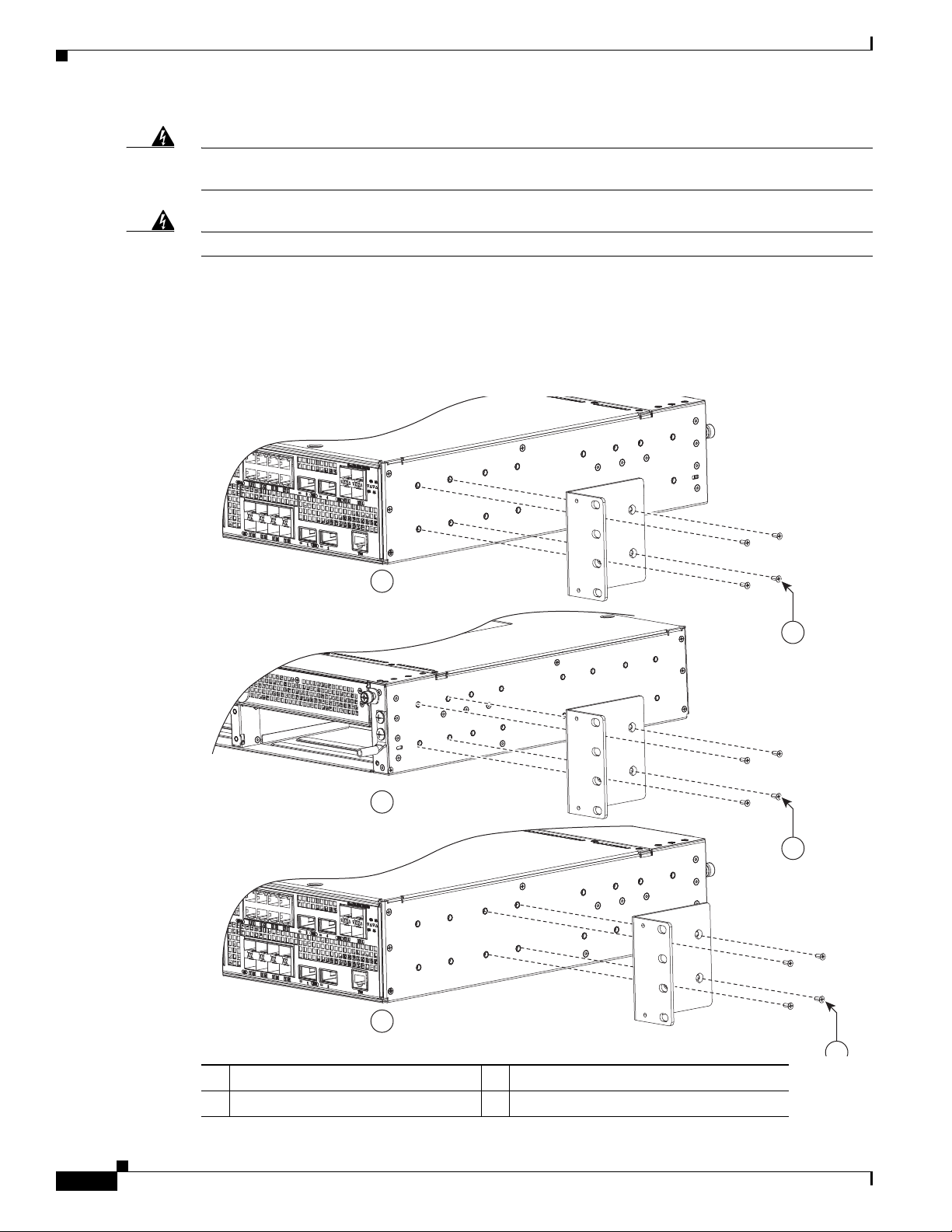
Attaching the Brackets
Use four Phillips flat-head screws to attach the long side of the brackets to the switches in one of
mounting positions.
Statement 1047
Statement 1074
1 Phillips flat-head screws 3 Rear-mounting position
2 Front-mounting position 4 Mid-rack mounting position
Cisco ME 3600X-24CX Switch Getting Started Guide
8
OL-27508-01
Page 9
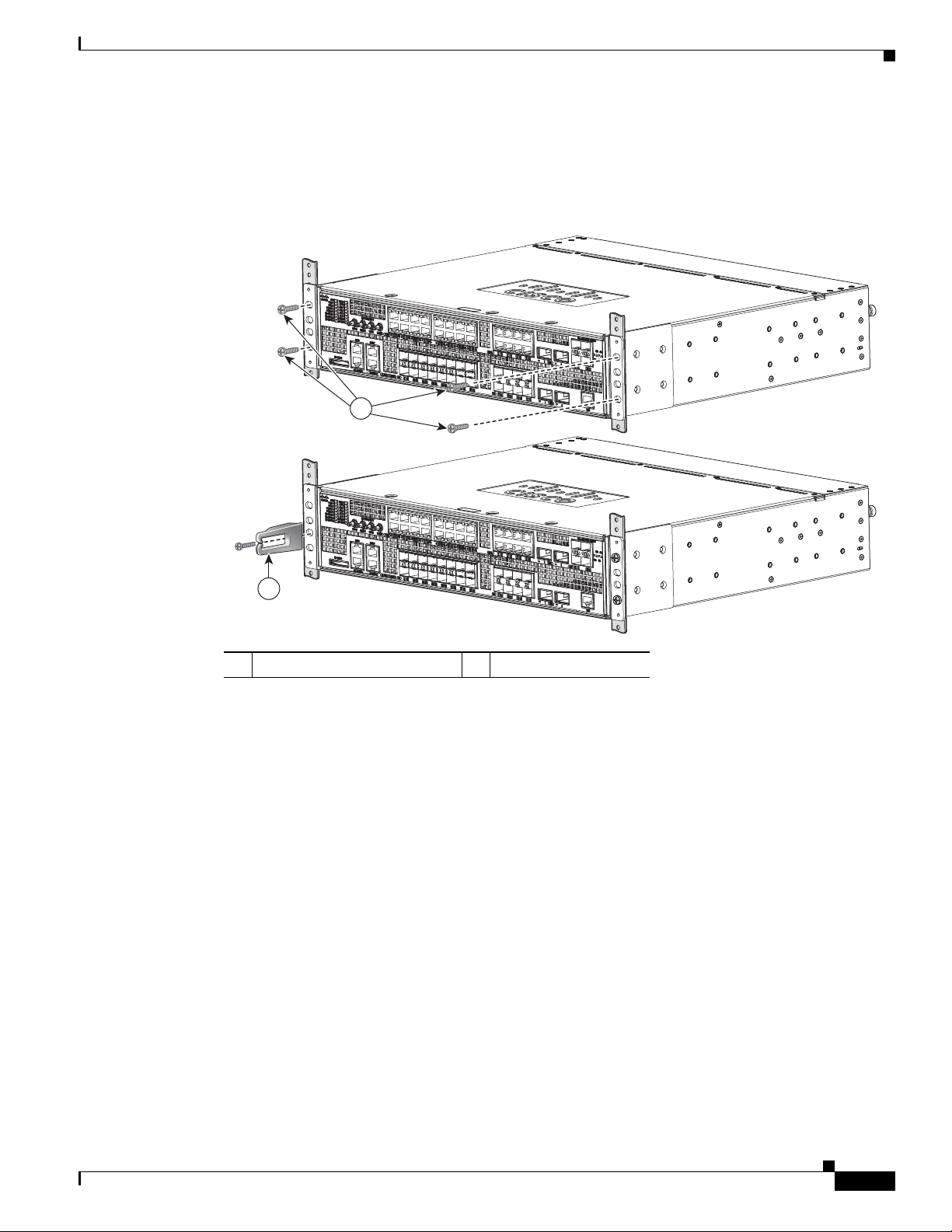
Rack-Mount the Switch
Use the black Phillips machine screw to attach the cable guide to the left or right bracket and the supplied
screws to attach the brackets to the rack.
Installing the Switch
1
2
1 Black Phillips machine screw 2 Cable guide and screw
333297
OL-27508-01
Cisco ME 3600X-24CX Switch Getting Started Guide
9
Page 10
Connecting to the Switch Ports
Connecting to the Switch Ports
This section describes how to connect to the fixed switch ports and to the SFP module ports. The switch
in the illustrations might be different from your switch, but the instructions apply to all Cisco ME 3800X
and ME 3600X switches.
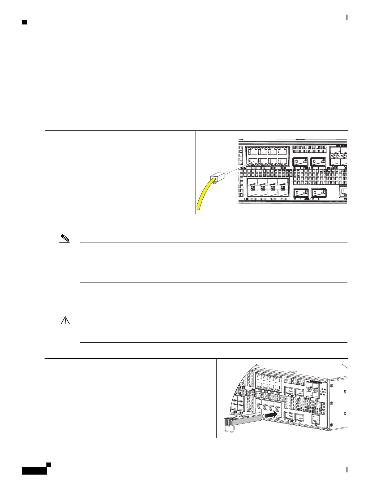
Connect to 10/100 or 10/100/1000 Ports
Step 1
Step 2
When you connect to servers, workstations,
customer-premises equipment (CPE), wireless access
points, and routers, connect a straight-through, twisted
four-pair, Category 5 cable to a switch 10/100 or
10/100/1000 port.
Use a crossover, twisted four-pair, Category 5 cable
when you connect to other switches, hubs, or repeaters.
Connect the other end of the cable to a connector on the other device.
Note The automatic medium-dependent interface crossover (auto-MDIX) feature is enabled by default. The
switch detects the required cable type for copper Ethernet connections and configures the interfaces
accordingly. You can use either a crossover or a straight-through cable for connections to a copper
10/100, 10/100/1000, or 1000BASE-T SFP module port on the switch, regardless of the type of device
on the other end of the connection.
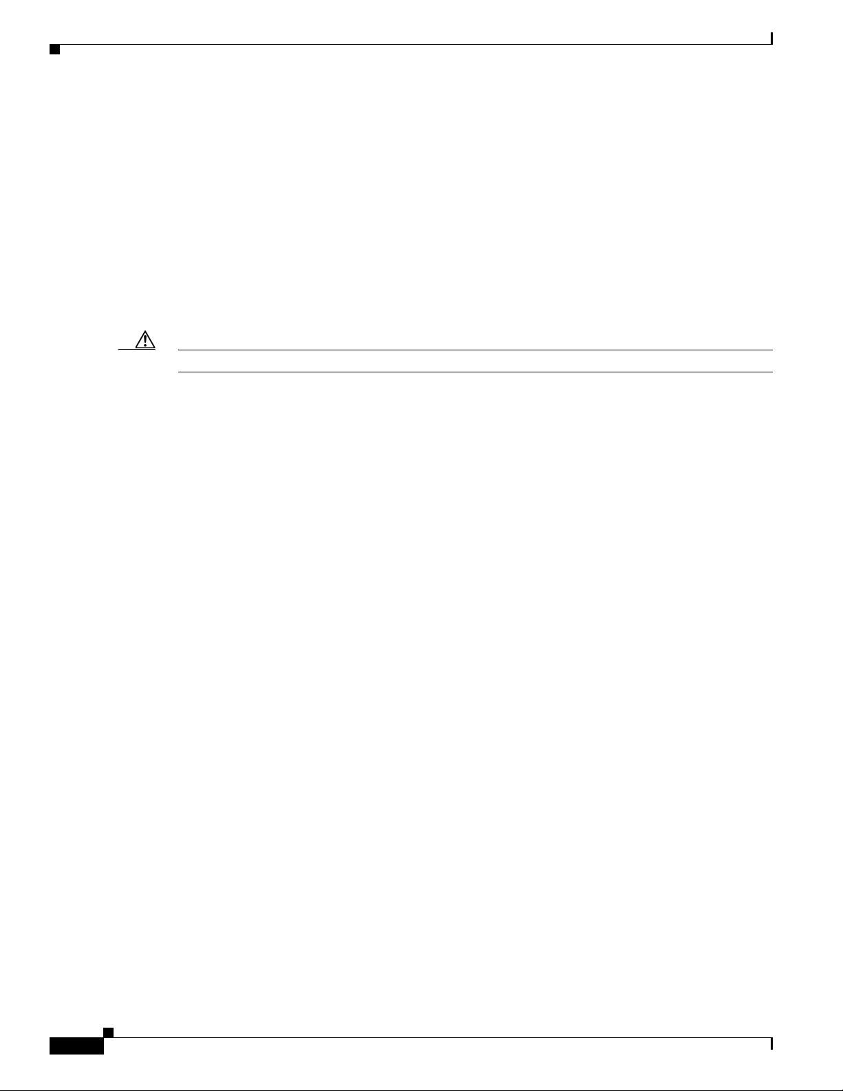
Install the XFP Modules and Connect to the Ports
Step 1
10
Caution To prevent damage to the XFP module, make sure that you verify the proper orientation of the module
by consulting the module documentation before you install it.
Grasp the XFP module on the sides, and insert it into the switch
slot until you feel the connector snap into place.
Cisco ME 3600X-24CX Switch Getting Started Guide
OL-27508-01
Page 11

Troubleshooting
Step 2
Connect an appropriate cable to the XFP module port. Connect
the other cable end into the other device.
For a list of supported modules, see the release notes on Cisco.com. For detailed instructions on
installing, removing, and connecting to XFP modules, see the XFP module documentation.
Caution Removing and installing an XFP module can shorten its useful life. Do not remove and insert SFP
modules more often than is absolutely necessary.
For instructions on using the XFP patch cable, see the “Switch Installation” chapter of the hardware
installation guide.
Verify Port Connectivity
After you connect to the switch port, the port LED turns amber while the switch establishes a link. This
takes about 30 seconds. After the switch and the target device establish a link, the port LED turns green.
If the LED is off, the target device might not be turned on, there might be a cable problem, or there might
be a problem with the adapter installed in the target device. See the “Troubleshooting” section on
page 11 for information about online assistance.
Troubleshooting
Initial Configuration Setup
If you have problems running the initial configuration dialog:
• Did you verify that POST ran successfully
before running the initial configuration
dialog?
• Did you press the Break key while the
switch was still running POST?
If not, make sure that only the System LED is green
before pressing the Break key or entering a break
character.
If yes, wait until POST completes. Restart the
switch. Wait until POST completes. Confirm that the
System LED is green. Enter
flash memory.
Reload to reinstall the
OL-27508-01
Cisco ME 3600X-24CX Switch Getting Started Guide
11
Page 12
Obtaining Documentation and Submitting a Service Request
• Did you wait 30 seconds after you
connected the switch and the PC before
you entered the IP address in your
browser?
• Did you forget your password? See the “Recovering from a Lost or Forgotten
Resetting the Switch to the Default Settings
Caution Resetting the switch deletes the configuration and restarts the switch.
To reset the switch:
• At the switch# prompt, enter enable, and press Return or Enter.
• At the switch# prompt, enter setup, and press Return or Enter.
The switch displays the prompt to run the initial configuration dialog. See the “Initial Setup” section on
page 3 to re-enter the configuration information and to set up your switch.
If not, wait 30 seconds, re-enter 10.0.0.1 in the
browser, and press Enter.
Password” section in the Troubleshooting appendix
of the software configuration guide.
Accessing Help Online
First look for a solution to your problem in the troubleshooting section of the hardware installation guide
or the software configuration guide on Cisco.com. You can also access the Cisco Technical Support and
Documentation website for a list of known hardware problems and extensive troubleshooting
documentation.
Obtaining Documentation and Submitting a Service Request
For information on obtaining documentation, submitting a service request, and gathering additional
information, see the monthly What’s New in Cisco Product Documentation, which also lists all new and
revised Cisco technical documentation, at:
http://www.cisco.com/en/US/docs/general/whatsnew/whatsnew.html
Subscribe to the What’s New in Cisco Product Documentation as a Really Simple Syndication (RSS) feed
and set content to be delivered directly to your desktop using a reader application. The RSS feeds are a free
service and Cisco currently supports RSS version 2.0.
For More Information
For more information about the switch, see these documents on Cisco.com:
• Cisco ME 3600X-24CX Switch Hardware Installation Guide
• Regulatory Compliance and Safety Information for the Cisco ME 3600X-24CX Switch
12
• Release Notes for the Cisco ME 3600X-24CX Switch
Cisco ME 3600X-24CX Switch Getting Started Guide
OL-27508-01
Page 13
Obtaining Documentation and Submitting a Service Request
• Cisco ME 3800X and ME 3600X Switch Software Configuration Guide
• Cisco ME 3800X and ME 3600X Switch Command Reference
• Cisco ME 3800X and ME 3600X Switch System Message Guide
Cisco and the Cisco logo are trademarks or registered trademarks of Cisco and/or its affiliates in the U.S. and other countries. To view a list of
Cisco trademarks, go to this URL: www.cisco.com/go/trademarks. Third-party trademarks mentioned are the property of their respective owners. The
use of the word partner does not imply a partnership relationship between Cisco and any other company. (1110R)
Any Internet Protocol (IP) addresses used in this document are not intended to be actual addresses. Any examples, command display output, and
figures included in the document are shown for illustrative purposes only. Any use of actual IP addresses in illustrative content is unintentional and
coincidental.
© 2010–2012 Cisco Systems, Inc. All rights reserved.
OL-27508-01
Cisco ME 3600X-24CX Switch Getting Started Guide
13
Page 14

Obtaining Documentation and Submitting a Service Request
14
Cisco ME 3600X-24CX Switch Getting Started Guide
OL-27508-01
 Loading...