

Page 1
Cisco Small Business
HGA9N High Gain Omni-Directional Antenna for
N Type Connectors
ADMINISTRATION
GUIDE
Page 2

CCDE, CCENT, CCSI, Cisco Eos, Cisco HealthPresence, Cisco Ironport, the Cisco logo, Cisco Lumin, Cisco Nexus, Cisco Nurse Connect, Cisco Stackpower,
Cisco StadiumVision, Cisco TelePresence, Cisco Unified Computing System, Cisco WebEx, DCE, Flip Channels, Flip for Good, Flip Mino, Flip Video, Flip Video
(Design), Flipshare (Design), Flip Ultra, and Welcome to the Human Network are trademarks; Changing the Way We Work, Live, Play, and Learn, Cisco Store, and
Flip Gift Card are service marks; and Access Registrar, Aironet, AsyncOS, Bringing the Meeting To You, Catalyst, CCDA, CCDP, CCIE, CCIP, CCNA, CCNP, CCSP,
CCVP, Cisco, the Cisco Certified Internetwork Expert logo, Cisco IOS, Cisco Press, Cisco Systems, Cisco Systems Capital, the Cisco Systems logo, Cisco Unity,
Collaboration Without Limitation, EtherFast, EtherSwitch, Event Center, Fast Step, Follow Me Browsing, FormShare, GigaDrive, HomeLink, Internet Quotient, IOS,
iPhone, iQuick Study, IronPort, the IronPort logo, LightStream, Linksys, MediaTone, MeetingPlace, MeetingPlace Chime Sound, MGX, Networkers, Networking
Academy, Network Registrar, PCNow, PIX, PowerPanels, ProConnect, ScriptShare, SenderBase, SMARTnet, Spectrum Expert, StackWise, The Fastest Way to
Increase Your Internet Quotient, TransPath, WebEx, and the WebEx logo are registered trademarks of Cisco Systems, Inc. and/or its affiliates in the United States
and certain other countries.
All other trademarks mentioned in this document or website are the property of their respective owners. The use of the word partner does not imply a
partnership relationship between Cisco and any other company. (0907R)
© 2009 Cisco Systems, Inc. All rights reserved. OL-20327-01
Page 3

Contents
About This Document 4
Chapter 1: Planning Your Wireless Antenna Coverage 5
The Antenna Pattern for Radio Waves 5
Optimizing Range 7
Placing the Omni-Directional Antenna 8
Using the Omni-Directional Antenna 8
How to Achieve Optimal Gain 9
Distance Calculation Examples 10
Chapter 2: Getting to Know the High Gain Omni-Directional Antenna 11
The Omni-Directional Antenna Port 11
Antenna Cable 12
The Lightning Protector (Surge Arrestor) 13
Mounting Kit 13
Chapter 3: Connecting the High Gain Omni-Directional Antenna 14
Appendix A: Product Specifications 20
Appendix B: Where to Go From Here 22
Cisco HGA9N Administration Guide 3
Page 4

About This Document
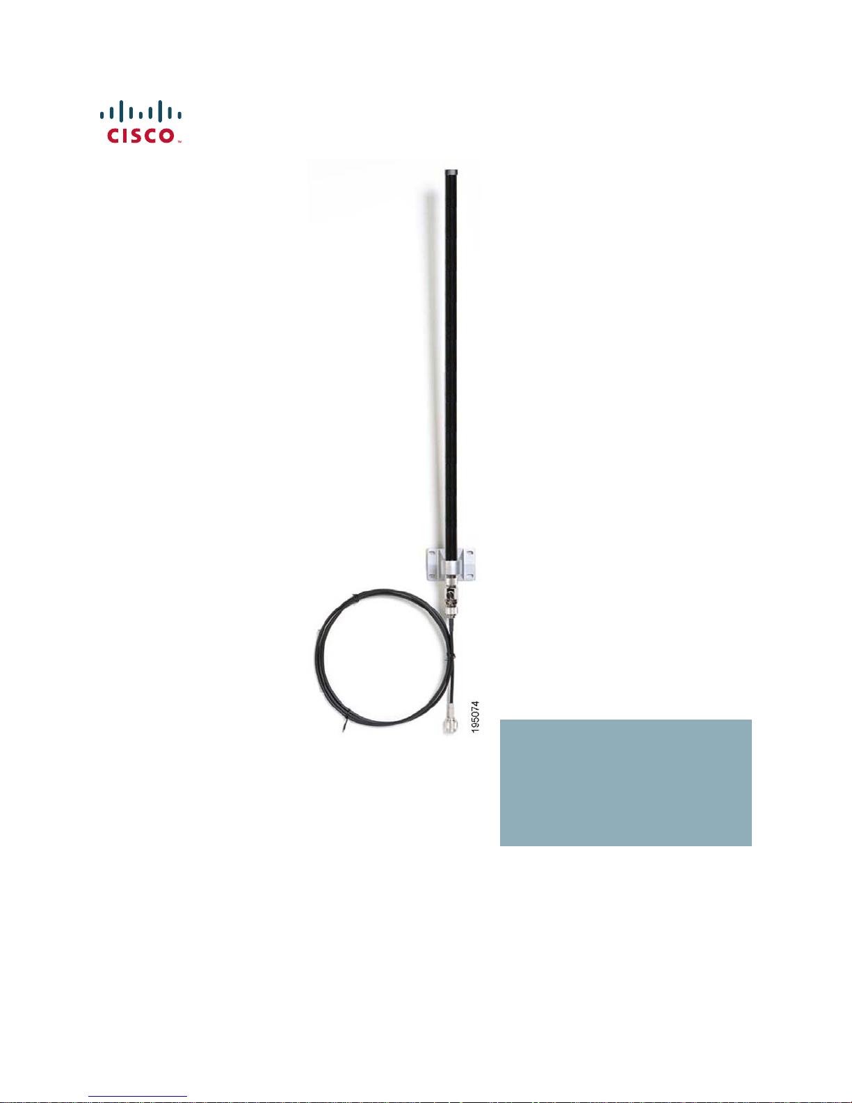
Thank you for choosing the Cisco HGA9N High Gain Omni-Directional Antenna for
N Type Connectors. The Antenna and the Cisco WAP200E Wireless-G Exterior
Access Point together provide 9dBi peak gain and should be used together. This
guide will help you set up and place the Antenna and the access point properly so
you can achieve optimal range.
Use the instructions in this Guide to further help you connect the 9dBi OmniDirectional Antenna to the Wireless-G Exterior Access Point and bridge your
different networks. These instructions should be all you need to get the most out
of the High Gain Omni-Directional Antenna.
Preface
WARNING This product contains chemicals, including lead, known to the State of California to
cause cancer, and birth defects or other reproductive harm.
handling.
Wash hands after
Cisco HGA9N Administration Guide 4
Page 5

Planning Your Wireless Antenna Coverage
The following sections describe how to plan your wireless antenna coverage:
• The Antenna Pattern for Radio Waves, page 5
• Optimizing Range, page 7
• Placing the Omni-Directional Antenna, page 8
• Using the Omni-Directional Antenna, page 8
1
• How to Achieve Optimal Gain, page 9
• Distance Calculation Examples, page 10
The Antenna Pattern for Radio Waves
The power of the wireless signal is most strong on the horizontal plane of the
Omni-Directional Antenna. The peak gain of this antenna is 9dBi. The diagrams
below show the antenna pattern of the 9dBi Omni-Directional Antenna on the
horizontal and vertical planes.
Cisco HGA9N Administration Guide 5
Page 6
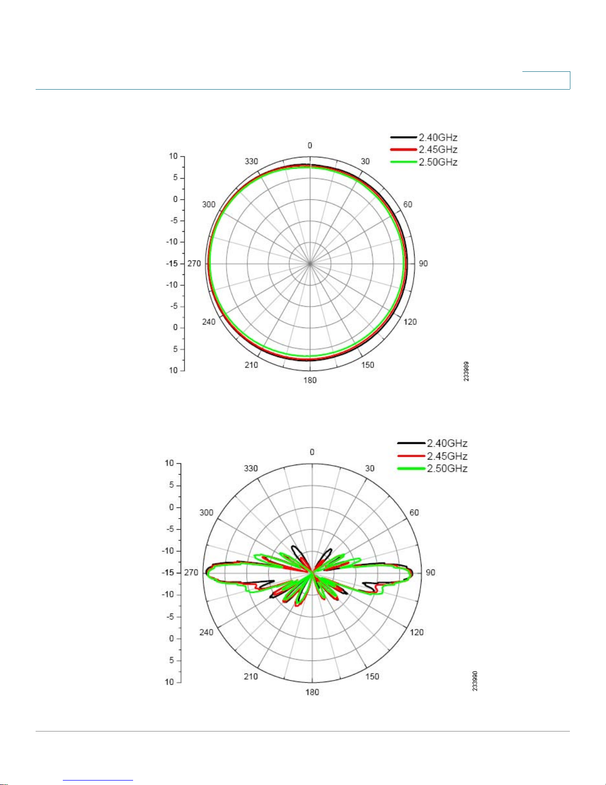
Figure1 Omni-Directional Antenna Pattern (Horizontal Plane)
1
Figure 2 Omni-Directional Antenna Pattern (Vertical Plane)
Cisco HGA9N Administration Guide 6
Page 7
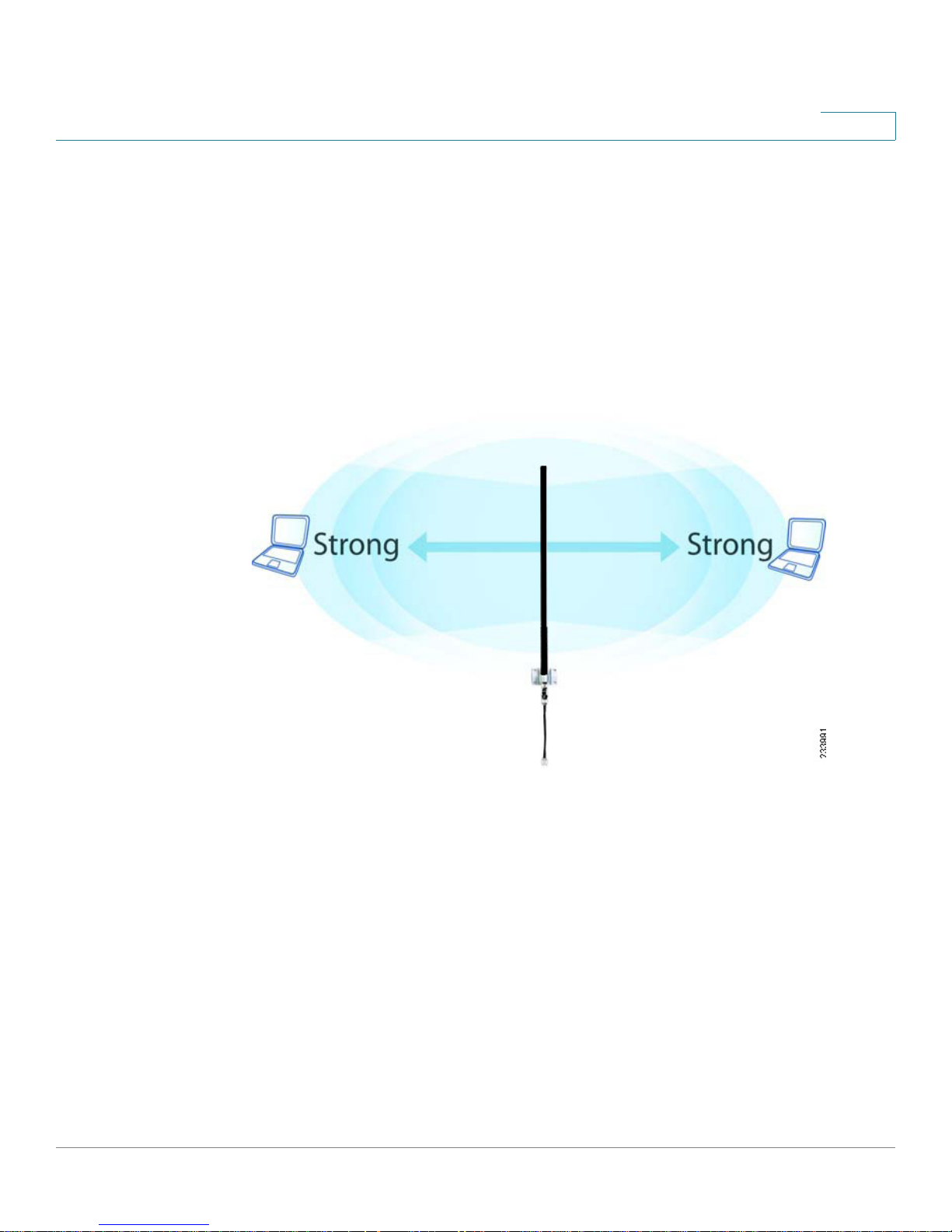
Optimizing Range
The power of the wireless signal is strongest on the horizontal plane of the OmniDirectional Antenna. In the figure, note the strongest ranges according to the
positioning of the Antenna.
For best results, Cisco recommends placing the Omni-Directional Antenna as
illustrated in the next figure.
Figure 3 Placing the Omni-Directional Antenna for Optimum Range
1
Cisco HGA9N Administration Guide 7
Page 8

Placing the Omni-Directional Antenna
Because the antenna is omni-directional, you have more flexibility with where you
can place the access point. Keep in mind, however, that the Omni-Directional
Antenna achieves its peak gain when your client PC (that is, a PC with a wireless
adapter) stays on the same horizontal plane as the Antenna.
• Line of sight—The minimum requirement is line of sight. If you can see the
receiver antenna, then you are within a suitable range.
• Avoid obstacles—Avoid obstacles and set up the Omni-Directional Antenna
and the other antennas as high as possible. Try to avoid trees, buildings, and
other objects close to the path between two antennas, because they can
reduce signal power.
1
Using the Omni-Directional Antenna
The Omni-Directional Antenna can be used with the access point for several
purposes:
• Access point to client devices—You can achieve better range and
transmission with the Omni-Directional Antenna when connecting the
wireless client (a PC with any wireless adapter) to the access point.
• Repeater mode—The Omni-Directional Antenna and access point can
repeat wireless signals from one access point to other devices, such as to a
client PC or to other repeaters.
• Point-to-multipoint bridging—The Omni-Directional Antenna connects to
one main access point. The main access point connects to other access
points that each use a separate Directional Antenna. To achieve maximum
distance coverage, the other access points are usually located in different
directions from the main access point.
NOTE The Omni-Directional Antenna does not provide extra value for point-to-point
bridging. You can achieve the same antenna gain by using the internal directional
antenna from the access point.
Cisco HGA9N Administration Guide 8
Page 9

How to Achieve Optimal Gain
Wireless coverage depends on several factors, including power and transmission.
You can calculate exact coverage distance by gathering the specifications of the
access point and the Omni-Directional Antenna and using the equation below.
TIP This equation is not required, but it may be beneficial in optimizing use of your
Omni-Directional Antenna and access point.
In this formula, everything is in dBm or dB.
1
S
is the received power. Here we plug in the receiver sensitivity to calculate the
r
maximum distance. For example, -82dBm for 11Mbps.
S
is the transmitted power. For example, 18dBm for 11Mbps.
t
G
is the transmitter antenna gain and
t
Omni-Directional Antenna).
G
is the receiver antenna gain (9dBi for this
r
λ is the wavelength of the signal. The product of λ and frequency equals to speed
of light (c).
d
is the distance.
LinkBudget
is the lump sum of additional loss (compared to free space) in the path.
Cisco HGA9N Administration Guide 9
Page 10

Distance Calculation Examples
You can use the information in the tables below to determine how you want to
place the Omni-Directional Antenna in relation to the access point to client device
or between the two access points.
As you can see, the higher the transmit data rate, the shorter the coverage
distance. Therefore, when a client device moves further away from an access
point, the data rate will fall back to a lower data rate.
Table1 Coverage Distance from Access Point to Client Devices
1
Data Rate
Distance 0.88 km
Table 2 Coverage Distance from Access Point to Access Point
Data Rate
Distance 2.49 km
To obtain these calculations, we inserted the specifications of the access point
into the formula as described previously. We use 9dBi peak antenna gain and
assume 0dBi antenna gain at the client device. Link budget is set to 10dB to
include radio wave attenuations from different types of objects in the path (the
actual value may vary).
11 Mbps 54 Mbps
0.12 km
.55 miles
11 Mbps 54 Mbps
1.56 mi le s
0.078 miles
0.35 km
0.22 miles
Cisco HGA9N Administration Guide 10
Page 11

Getting to Know the High Gain OmniDirectional Antenna
This chapter explains the components that come with the Cisco HGA9N High Gain
Omni-Directional Antenna and contains the following sections:
• The Omni-Directional Antenna Port, page 11
• Antenna Cable, page 12
2
• The Lightning Protector (Surge Arrestor), page 13
• Mounting Kit, page 13
The Omni-Directional Antenna Port
The Omni-Directional Antenna has only one port in the tip closer to the mounting
bracket. For installation purposes, it is important to note that the antenna port has a
female N-type connector and should only be connected to the male cable
connector.
Figure 4 Omni-Directional Antenna Port
Cisco HGA9N Administration Guide 11
Page 12

Antenna Cable
2
One six-foot low-loss antenna cable is included with this product and is used to
connect the Omni-Directional Antenna to the access point. Note that the two
connectors have different polarities and one connector is marked with white tape.
The connector with white tape connects to the access point.
Figure 5 Antenna Cable
Cisco HGA9N Administration Guide 12
Page 13

The Lightning Protector (Surge Arrestor)
The lightning protector is used to protect your 9dBi Omni-Directional Antenna
when it is used in an outdoor environment. The lightning protector screws into the
end of the Antenna. Although it is not required, Cisco recommends using the
lightning protector to help prevent damage to equipment.
Figure 6 Lightning Protector
2
Mounting Kit
A kit including U-clamps, nuts, washers, and screws are provided to mount the
Omni-Directional Antenna.
Cisco HGA9N Administration Guide 13
Page 14

3
Connecting the High Gain Omni-Directional
Antenna
This chapter explains how to mount and connect the Cisco HGA9N High Gain
Omni-Directional Antenna to the Wireless-G Exterior Access Point.
STEP 1 Make sure you have all of the hardware displayed below, including a plastic bag
containing the mounting hardware. The following figures are found in a typical
external Omni-Directional Antenna setup.
Figure 7 Omni-Directional Antenna Port
Figure 8 Lightning Protector
Cisco HGA9N Administration Guide 14
Page 15

Figure 9 Antenna Cable
3
Figure10 Exterior Access Point
STEP 2 Obtain a location for the 9dBi Omni-Directional Antenna. The location should have
a clear view to the peer Antenna. For detailed information about adjusting the 9dBi
Omni-Directional Antenna for your application, see “The Antenna Pattern for
Radio Waves” on page 5 .
STEP 3 Determine whether you will mount the Omni-Directional Antenna to a pole or a
wall. Follow the mounting instructions as displayed.
Wall Mounting
Your wall mounting package should contain the following items. Items are
numbered to correspond with the wall mount example in Figure 11.
1. Omni-Directional Antenna—1 pc
2. Sticker—2 pcs
Cisco HGA9N Administration Guide 15
Page 16

3. Plastic Fixings—4 pcs
4. Holder—1 pc
5. Washers—4 pcs
6. Screws—4 pcs
Figure11 Wall Mount Example
3
Pole Mounting
Your pole mounting package should contain the following items. Items are
numbered to correspond with the wall mount example in Figure 12.
1. Omni-Directional Antenna—1 pc
2. Hose clamp—2 pcs
3. Holder—1 pc
Cisco HGA9N Administration Guide 16
Page 17

4. Washers—4 pcs
5. Screw nuts—4 pcs
Figure12 Pole Mount Example
3
STEP 4 The bottom of the Omni-Directional Antenna has a removable black covering.
Remove the black covering and attach the lightning protector as illustrated below
by inserting the male end of the protector into the Antenna.
Cisco HGA9N Administration Guide 17
Page 18

Figure13 Connect the Lightning Protector to the Antenna
3
Figure14 Connect the Cable to the Lightning Protector
Cisco HGA9N Administration Guide 18
Page 19

STEP 5 Attach the male end of the cable that has the white tape around it to the
Wireless-G Exterior Access Point.
Figure15 Connect the Access Point to the Cable
3
STEP 6 If you are mounting to a pole, insert the pole (not included) into the mounting
bracket assembly. As discussed previously, the pole must give the antenna at least
2 meters of clearance from the ground.
STEP 7 If you are mounting to a base (not included), make sure the base is secure.
Congratulations! The connection is complete. You can begin using the
Cisco HGA9N High Gain Omni-Directional Antenna.
Cisco HGA9N Administration Guide 19
Page 20

Product Specifications
The table below contains product specifications for the Cisco HGA9N High Gain
Omni-Directional Antenna.
Specification Description
Model HGA9N
A
Ports 1 N-type female connector
Cabling Type Coax - 50 Ohm impedance
Frequency Range 2400 MHz - 2500 MHz
Peak Gain 9 dBi
VSWR 1.92: 1 Max
Polarization Linear, vertical
HPBW / horizontal 360º
HPBW / vertical 11º
Impedance 50 Ohms
Range Maximum Outdoor range:
0.88 km (0.55 mi) at 11 Mbps
•
• 0.12 km (0.078 mi) at 54Mbps
NOTE Range estimation is based on one WAP54GPE
Access point with an HGA9N Omni-Directional Antenna
attached to a wireless client with a 0dBi antenna under ideal
line-of-sight conditions.
Dimensions 2.95” x 24.6” x 2.20” (75 x 625 x 56mm)
Cisco HGA9N Administration Guide 20
Page 21

Specification Description (Continued)
Mounting Options Mounting kit provided
A
Operating
Te m p e r a t u r e
Storage Temperature 22 to 176ºF (-30ºC to 80ºC)
Operating Humidity 5% to 95%, non-condensing
Storage Humidity 5% to 95%, non-condensing
-22 to 176ºF (-30ºC to 80ºC)
Cisco HGA9N Administration Guide 21
Page 22

Where to Go From Here
Cisco provides a wide range of resources to help you and your customer obtain
the full benefits of the Cisco HGA9N High Gain Omni-Directional Antenna.
Support
B
Cisco Small Business
Support Community
Online Technical Support
and Documentation
(Login Required)
Phone Support Contacts www.cisco.com/en/US/support/tsd_cisco_small_
Software Downloads
(Login Required)
Product Documentation
Cisco Small Business
Wireless Solutions index
Cisco HGA9N Quick
Start Guide
Cisco Small Business
Cisco Partner Central for
Small Business (Partner
Login Required)
www.cisco.com/go/smallbizsupport
www.cisco.com/support
business_support_ center_contacts.html
Go to tools.cisco.com/support/downloads, and enter
the model number in the Software Search box.
www.cisco.com/cisco/web/solutions/small_
business/products/wireless/index.html
www.cisco.com/en/US/products/ps10056/
index.html
www.cisco.com/web/partners/sell/smb
Cisco Small Business
Home
Marketplace www.cisco.com/go/marketplace
Cisco HGA9N Administration Guide 22
www.cisco.com/smb
 Loading...