

Cisco 12016, 12416, 12816, GSR16-BLOWER=, 12000/10/16-BLWER= Replacement Instructions Manual
...
Cisco 12016, Cisco 12416, and Cisco 12816 Router
Blower Module and Air Filter
Replacement Instructions
Cisco Product Numbers: GSR16-BLOWER=, 12000/10/16-BLWER=, ACS-GSR16-FLTR=
This publication contains removal and replacement procedures for the blower module and chassis air
filter in Cisco 12016, Cisco 12416, and Cisco 128 16 routers. Unless otherwise noted, all information in
this publication applies to all router models.
Note The illustrations in this guide represent both the original and newer enhanced capacity blower modules,
and air filters for the Cisco 12016, Cisco 12416, and Cisco 12816 routers. Depending on your system,
these components may not look exactly like those in your chassis, but the removal and replacement
procedures are essentially the same. For clarity, most chassis covers are not shown in the illustrations.
Blower Module Compatibility
There are currently two types of blower modules in use for the Cisco 12016, Cisco 12416, and Cisco
12816 routers; blowers that shipped with original sy stems, and enhanced capacity blowers that ship wi th
current systems.
If you are replacing an:
• Original blower module (GSR16-BLOWER=)—Use an original blower module or enhanced
capacity blower modules as replacements.
Caution You cannot mix original and enhanced capacity blower modules in the same chassis. Both the upper and
lower blower modules must be identical.
• Enhanced capacity blower module (12000/10/16-BLWER=)—Use an enhanced capacity blower
module as a replacement.
Corporate Headquarters:
Cisco Systems, Inc., 170 West Tasman Drive, San Jose, CA 95134-1706 USA
Copyright © 2005 Cisco Systems, Inc. All rights reserved.

Contents
Contents
The following sections are included in this publication:
• Prerequisites and Preparation, page 2
• Installation Guidelines, page 4
• Removing and Replacing the Blower Modules, page 4
• Troubleshooting the Installation, page 7
• Cleaning or Replacing the Chassis Air Filter, page 7
• Regulatory, Compliance, and Safety Information, page 12
• Obtaining Documentation, page 14
• Obtaining Technical Assistance, page 15
• Obtaining Additional Publications and Information, page 16
Prerequisites and Preparation
Before you perform any of the procedures in this guide, we recommend that you:
• Read the safety and ESD-prevention guidelines in this section.
• Ensure that you have all of the necessary tool s and equip ment before b e ginning the installat ion (see
• Have access to the following documents during the installation:
For additional information about obtaining documentation see the “Obtaining Documentation” section
on page 14.
Safety Guidelines
Before you perform any procedure in this publication, review the safety guidelines in this section to
avoid injuring yourself or damaging the equipment.
Safety Warnings
Safety warnings appear throughout this publication in procedures that, if performed incorrectly, may
harm you. A warning symbol precedes each warning statement. The following warning is an example of
a safety warning. It identifies the wa rning sy mbol and associates it with a bodily injury hazard.
the “Installation Guidelines” section on page 4).
–
Regulatory Compliance and Safety Information for the Cisco 12016, Cisco 12416, and
Cisco 12816 Series Router publication that shipped with the router (PN 78-4347-xx)
–
Cisco 12016, Cisco 12416, and Cisco 12816 Router Installation and Configuration Guide
Warning
Cisco 12016, Cisco 12416, and Cisco 12816 Router Blower Module and Air Filter Replacement Instructions
2
This warning symbol means danger. You are in a situation that could cause bodily injury. Before you
work on any equipment, be aware of the hazards involved with electrical circuitry and be familiar
with standard practices for preventing accidents. To see translations of the warnings that appear in
this publication, refer to the Regulatory Compliance and Safety Information document that
accompanied this device.
78-16083-02
26208
Preventing Electrostatic Discharge Damage
Many router components can be damaged by static electricity. Not exercising the proper electrostatic
discharge (ESD) precautions can result in intermittent or complete component f ailures. To minimize the
potential for ESD damage, always use an ESD-preventive antistatic wrist strap (or ankle strap) and
ensure that it makes good skin conta ct.
Note Y ou should periodically check the resistance value of the ESD-prev entive strap. Ensure the measurement
is between 1 and 10 megohms.
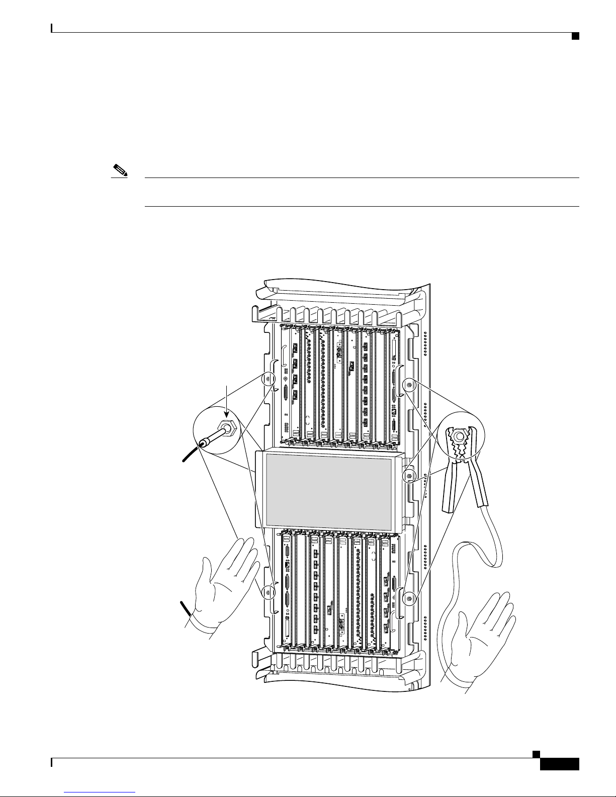
Before performing the procedures in this guide, att ach an ESD-preven tive strap to your wr ist and connect
the leash to the chassis or to another grounded, bare metal surface as shown in Figure 1.
Figure 1 Connecting an ESD-Preventive Wrist Strap to the Chassis
DOWN
LOOP RA LA
DOWN
LOOP RA LA
CDHNT CD
CDHNT CD
TX
TX
0
0
RX
RX
0
TX
TX
1
1
RX
RX
ACTIVE
CARRIER
TX
TX
RX PKT
2
2
RX
RX
TX
TX
ESD
connection
socket
1
3
ACTIVE
ACTIVE
CARRIER
RX PKT
2
ACTIVE
CARRIER
RX PKT
3
ACTIVE
CARRIER
RX PKT
Q OC-3/STM-POS
3
CARRIER
RX
RX
RX PKT
TX
TX
4
4
RX
RX
TX
TX
5
5
RX
RX
TX
6
RX
TX
7
RX
TX
8
RX
TX
9
RX
TX
10
RX
TX
11
OC-48/STM-16-SCPOS
RX
12DS3–SMB P
6DS3–SMB P
/
/
H
H
/
/
F
F
CRITICAL
MAJOR
MINOR
ACO/LT
ALARM
ENABLED
FAIL
ENABLED
FAIL
0
CSC
1
0
1
SFC
ALARM
2
Prerequisites and Preparation
EJECT
SLOT-0
0
ACTIVE
CARRIER
RX CELL
OC-12/STM-4 ATM
FAST ETERNET
SLOT-1
RESET
AUX
CONSOLE
LINK
COLL
TX
RX
MII
RJ-45
ROUTE PROCESSOR
O
O
O
O
O
O
O
O
O
O
O
O
O
O
O
O
O
O
O
O
O
O
O
O
O
O
O
O
O
O
O
O
O
O
O
O
O
O
O
O
O
O
O
O
O
O
O
O
O
O
O
O
O
O
O
O
O
O
O
O
O
O
O
O
O
O
O
O
O
O
O
O
O
O
O
O
O
O
O
O
O
O
O
O
O
O
O
O
O
O
O
O
O
O
O
O
O
ROUTE PROCESSOR
FAST ETERNET
RJ-45
MII
RX
TX
COLL
LINK
CONSOLE
AUX
RESET
SLOT-1
SLOT-0
EJECT
RX CELL
CARRIER
ACTIVE
F
F
/
/
H
H
/
/
2
ALARM
SFC
1
OC-12/STM-4 ATM
12DS3–SMB P
RX
OC-48/STM-16-SCPOS
11
TX
RX
10
TX
RX
9
TX
RX
8
TX
RX
7
TX
RX
6
TX
RX
5
TX
RX
4
TX
RX PKT
RX
CARRIER
0
3
ACTIVE
TX
RX
2
TX
RX
1
TX
RX
0
TX
CDHNT CD
LOOP RA LA
DOWN
0
6DS3–SMB P
1
CSC
Q OC-3/STM-POS
0
FAIL
ENABLED
FAIL
ENABLED
RX PKT
CARRIER
ACTIVE
3
ALARM
RX PKT
CARRIER
ACTIVE
ACO/LT
RX
5
2
TX
RX
4
RX PKT
MINOR
CARRIER
TX
MAJOR
ACTIVE
CRITICAL
RX
3
1
TX
RX
2
RX PKT
TX
CARRIER
ACTIVE
RX
1
TX
0
RX
0
TX
CDHNT CD
LOOP RA LA
DOWN
Cisco 12016, Cisco 12416, and Cisco 12816 Router Blower Module and Air Filter Replacement Instructions
78-16083-02
3
Installation Guidelines
Installation Guidelines
The blower modules support online inser tion and remov al (O IR), so you can remo ve and install a b lower
module while the system remains powered on without presenting an electrical hazard or damage to the
system. Y ou can replace a blower module while the
session preservation.
Caution Although th e blower module support s OIR and can be replaced without interruption to system operation,
the system should not operate without a blower module for more than 3 minutes to prevent overheating.
Caution You cannot mix blower types within the chassis. If you are replacing a blower module from an old system
(GSR16-BLOWER=)
replacement blowers (12000/10/16-BLWER=). Although the blower modules can be replaced without
interruption to system operation, the system should not operate with mixed blower modules in the router
for more than 5 minutes.
system maintains all routing information and ensures
, you must replace both upper and lo wer bl ower mo dules with ne w, higher capacity
Required Tools and Equipment
You need the following tools and equipment to install the blower module:
• Number 2 Phillips screwdriver
• 3/16-inch flat-blade screwdriver
• An electrostatic discharge (ESD) preventive wrist or ankle strap with connection cord
• Vacuum cleaner (to clean the air filters)
Removing and Replacing the Blower Modules
This section contains the procedure to remove and replace the upper or lower blower modules from the
chassis. Before beginning either of these procedures, be sure to read the “Install ation Guidelines” se ction
on page 4.
Upper and Lower Blower Module Orientation
Illustrations in this procedure show the removal and replacement of the upper blower module. The
procedure to replace the lower blower module is the same except for the orientation of the blower
module.
• Heads-up orientation—Install the blo wer module in the upper bay in the “h eads-up” orientation with
the three fan air intake openings face down.
• Heads-down orientation—Install the blower module in the lower blower module bay in the
“heads-down” orientation with the three fan air intake openings face up.
Cisco 12016, Cisco 12416, and Cisco 12816 Router Blower Module and Air Filter Replacement Instructions
4
78-16083-02
Use the following procedure to remove and replace the blower modules.
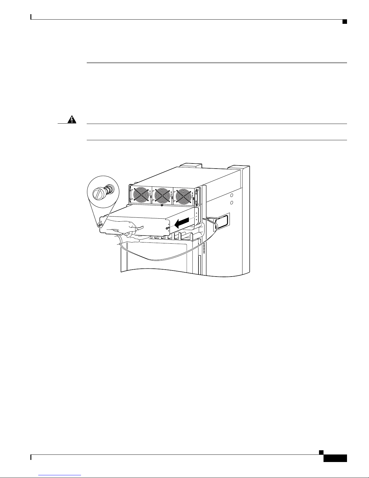
Step 1 Remove the blower module from the chassis (Figure 2):
a. Loosen the captive screw on each side of the blower module.
b. Pull out the blower module halfway from the module bay.
c. Slide out the blow er module completely from the module bay while supporting it with your other
hand.
Removing and Replacing the Blower Modules
Warning
The blower module weighs approximately 20 pounds (9 kg). Use two hands when handling the blowe r
module.
Figure 2 Removing the Upper Blower Module
PWR OK
FAULT
TEMP
I LIM
PWR OK
FAULT
TEMP
I LIM
PWR OK
FAULT
TEMP
I LIM
26213
Cisco 12016, Cisco 12416, and Cisco 12816 Router Blower Module and Air Filter Replacement Instructions
78-16083-02
5
Removing and Replacing the Blower Modules
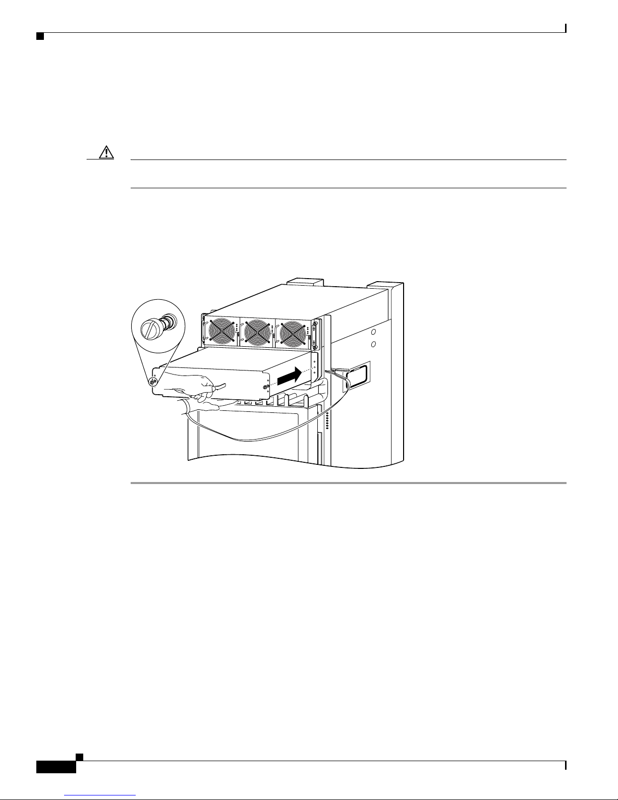
Step 2 Install the new blower module into the chassis (Figure 3):
a. Lift the blow er module (with two hands) and slide it halfway into the module bay.
b. Slowly push the blower module into the chassis until it mates with the backplane connector at the
back of the module bay.
Caution To prevent damage to the connectors, do not use excessive force when inserting the blower module into
the chassis.
c. Tighten the captive screws on the blower module to secure it to the chassis.
• The (green) OK status indicator on the front of the blower module should light. If the OK indicator
does not light, see the “Troubleshooting the Installation” section on page 7.
Figure 3 Installing the Upper Blower Module
PWR OK
FAULT
TEMP
I LIM
PWR OK
FAULT
TEMP
I LIM
PWR OK
FAULT
TEMP
I LIM
27218
Cisco 12016, Cisco 12416, and Cisco 12816 Router Blower Module and Air Filter Replacement Instructions
6
78-16083-02
 Loading...