

Cisco 12000 - Series Chassis Modular Expansion Base, GSR12/60-RF - 12012 Router, 12000 Series Hardware Installation Manual
Page 1

Americas Headquarters
Cisco Systems, Inc.
170 West Tasman Drive
San Jose, CA 95134-1706
USA
http://www.cisco.com
Tel: 408 526-4000
800 553-NETS (6387)
Fax: 408 527-0883
Cisco 12000 Series Router SIP and SPA
Hardware Installation Guide
June 26, 2006
Text Part Number: OL-8831-01, Rev. G4
Page 2

THE SPECIFICATIONS AND INFORMATION REGARDING THE PRODUCTS IN THIS MANUAL ARE SUBJECT TO CHANGE WITHOUT NOTICE. ALL
STATEMENTS, INFORMATION, AND RECOMMENDATIONS IN THIS MANUAL ARE BELIEVED TO BE ACCURATE BUT ARE PRESENTED WITHOUT
WARRANTY OF ANY KIND, EXPRESS OR IMPLIED. USERS MUST TAKE FULL RESPONSIBILITY FOR THEIR APPLICATION OF ANY PRODUCTS.
THE SOFTWARE LICENSE AND LIMITED WARRANTY FOR THE ACCOMPANYING PRODUCT ARE SET FORTH IN THE INFORMATION PACKET THAT
SHIPPED WITH THE PRODUCT AND ARE INCORPORATED HEREIN BY THIS REFERENCE. IF YOU ARE UNABLE TO LOCATE THE SOFTWARE LICENSE
OR LIMITED WARRANTY, CONTACT YOUR CISCO REPRESENTATIVE FOR A COPY.
The following inform ation is for FCC compliance of Class A devices: This equipment has been tested and found to comply with the limits for a Class A digital device, pursuant
to part 15 of the FCC rules. These limits are designed to provide reasonable protection against harmful interference when the equipment is operated in a commercial
environment. This equipment generates, uses, and can radiate radio-frequency energy and, if not installed and used in accordance with the instruction manual, may cause
harmful interference to radio communications. Operation of this equipment in a residential area is likely to cause harmful interference, in which case users will be required
to correct the interference at their own expense.
The following information is for FCC compliance of Class B devices: The equipment described in this manual generates and may radiate radio-frequency energy. If it is not
installed in accordance with Cisco’s installation instructions, it may cause interference with radio and television reception. This equipment has been tested and found to
comply with the limits for a Class B digital device in accordance with the specifications in part 15 of the FCC rules. These specifications are designed to provide reasonable
protection against such interference in a residential installation. However, there is no guarantee that interference will not occur in a particular installation.
Modifying the equipment without Cisco’s written authorization may result in the equipment no longer complying with FCC requirements for Class A or Class B digital
devices. In that event, your right to use the equipment may be limited by FCC regulations, and you may be required to correct any interference to radio or television
communications at your own expense.
You can determine whether your equipment is causing interference by turning it off. If the interference stops, it was probably caused by the Cisco equipment or one of its
peripheral devices. If the equipment causes interference to radio or television reception, try to correct the interference by using one or more of the following measures:
• Turn the television or radio antenna until the interference stops.
• Move the equipment to one side or the other of the television or radio.
• Move the equipment farther away from the television or radio.
• Plug the equipment into an outlet that is on a different circuit from the television or radio. (That is, make certain the equipment and the television or radio are on circuits
controlled by different circuit breakers or fuses.)
Modifications to this product not authorized by Cisco Systems, Inc. could void the FCC approval and negate your authority to operate the product.
The Cisco implementation of TCP header compression is an adaptation of a program developed by the University of California, Berkeley (UCB) as part of UCB’s public
domain version of the UNIX operating system. All rights reserved. Copyright © 1981, Regents of the University of California.
NOTWITHSTANDING ANY OTHER WARRANTY HEREIN, ALL DOCUMENT FILES AND SOFTWARE OF THESE SUPPLIERS ARE PROVIDED “AS IS” WITH
ALL FAULTS. CISCO AND THE ABOVE-NAMED SUPPLIERS DISCLAIM ALL WARRANTIES, EXPRESSED OR IMPLIED, INCLUDING, WITHOUT
LIMITATION, THOSE OF MERCHANTABILITY, FITNESS FOR A PARTICULAR PURPOSE AND NONINFRINGEMENT OR ARISING FROM A COURSE OF
DEALING, USAGE, OR TRADE PRACTICE.
IN NO EVENT SHALL CISCO OR ITS SUPPLIERS BE LIABLE FOR ANY INDIRECT, SPECIAL, CONSEQUENTIAL, OR INCIDENTAL DAMAGES, INCLUDING,
WITHOUT LIMITATION, LOST PROFITS OR LOSS OR DAMAGE TO DATA ARISING OUT OF THE USE OR INABILITY TO USE THIS MANUAL, EVEN IF CISCO
OR ITS SUPPLIERS HAVE BEEN ADVISED OF THE POSSIBILITY OF SUCH DAMAGES.
CCVP, the Cisco Logo, and the Cisco Square Bridge logo are trademarks of Cisco Systems, Inc.; Changing the Way We Work, Live, Play, and Learn is a service mark of
Cisco Systems, Inc.; and Access Registrar, Aironet, BPX, Catalyst, CCDA, CCDP, CCIE, CCIP, CCNA, CCNP, CCSP, Cisco, the Cisco Certified Internetwork Expert logo,
Cisco IOS, Cisco Press, Cisco Systems, Cisco Systems Capital, the Cisco Systems logo, Cisco Unity, Enterprise/Solver, EtherChannel, EtherFast, EtherSwitch, Fast Step,
Follow Me Browsing, FormShare, GigaDrive, HomeLink, Internet Quotient, IOS, iPhone, IP/TV, iQ Expertise, the iQ logo, iQ Net Readiness Scorecard, iQuick Study,
LightStream, Linksys, MeetingPlace, MGX, Networking Academy, Network Registrar, Packet, PIX, ProConnect, RateMUX, ScriptShare, SlideCast, SMARTnet, StackWise,
The Fastest Way to Increase Your Internet Quotient, and TransPath are registered trademarks of Cisco Systems, Inc. and/or its affiliates in the United States and certain other
countries.
All other trademarks mentioned in this document or Website are the property of their respective owners. The use of the word partner does not imply a partnership relationship
between Cisco and any other company. (0704R)
Cisco 12000 Series Router SIP and SPA Hardware Installation Guide
Copyright © 2007 Cisco Systems, Inc. All rights reserved.
Page 3

iii
Cisco 12000 Series Router SIP and SPA Hardware Installation Guide
Release 12.0(32)SY1, OL-8831-01, Rev. G6, July 19, 2007
CONTENTS
Preface xiii
Document Change History xiii
Objectives xv
Organization xv
Related Documentation xv
Obtaining Documentation xv
Cisco.com xvi
Product Documentation DVD xvi
Ordering Documentation xvi
Documentation Feedback xvii
Cisco Product Security Overview xvii
Reporting Security Problems in Cisco Products xvii
Obtaining Technical Assistance xviii
Cisco Technical Support & Documentation Website xviii
Submitting a Service Request xix
Definitions of Service Request Severity xix
Obtaining Additional Publications and Information xix
CHAPTER
1 Overview: Cisco 12000 Series Router SPA Interface Processors 1-1
SIP and SPA Compatibility 1-1
Router Hardware Installation 1-2
Supported Platforms 1-2
Power Management 1-2
SIP Summary 1-3
SIP Software and Hardware Compatibility 1-3
Cisco 12000 SIP-400 Overview 1-4
Cisco 12000 SIP-400 Board Components 1-4
Cisco 12000 SIP-400 LEDs 1-5
Cisco 12000 SIP-400 Physical Specifications 1-6
SPA Slot Numbering on the Cisco 12000 SIP-400 1-6
SPA Interface Addresses on the Cisco 12000 SIP-400 1-7
Cisco 12000 SIP-600 Overview 1-8
Page 4

Contents
iv
Cisco 12000 Series Router SIP and SPA Hardware Installation Guide
Release 12.0(32)SY1, OL-8831-01, Rev. G6, July 19, 2007
Cisco 12000 SIP-600 Board Components 1-8
Cisco 12000 SIP-600 LEDs 1-8
Cisco 12000 SIP-600 Physical Specifications 1-9
SPA Subslot Numbering on the Cisco 12000 SIP-600 1-9
SPA Interface Addresses on the Cisco 12000 SIP-600 1-10
Cisco 12000 SIP-401 Overview 1-11
Cisco 12000 SIP-401 Board Components 1-11
Cisco 12000 SIP-401 LEDs 1-11
Cisco 12000 SIP-401 Physical Specifications 1-12
SPA Slot Numbering on the Cisco 12000 SIP-401 1-12
SPA Interface Addresses on the Cisco 12000 SIP-401 1-13
Cisco 12000 SIP-501 Overview 1-14
Cisco 12000 SIP-501 Board Components 1-15
Cisco 12000 SIP-501 LEDs 1-15
Cisco 12000 SIP-501 Physical Specifications 1-16
SPA Subslot Numbering on the Cisco 12000 SIP-501 1-16
SPA Interface Addresses on the Cisco 12000 SIP-501 1-17
Cisco 12000 SIP-601 Overview 1-18
Cisco 12000 SIP-601 Board Components 1-18
Cisco 12000 SIP-601 LEDs 1-18
Cisco 12000 SIP-601 Physical Specifications 1-19
SPA Subslot Numbering on the Cisco 12000 SIP-601 1-20
SPA Interface Addresses on the Cisco 12000 SIP-601 1-20
CHAPTER
2 Overview: Cisco 12000 Series Router Shared Port Adapters 2-1
SPA Summary 2-1
Checking Hardware and Software Compatibility 2-2
Bandwidth Oversubscription 2-3
2-Port and 4-Port T3/E3 Serial SPA Overview 2-4
2-Port and 4-Port Clear Channel T3/E3 SPA LEDs 2-4
2-Port and 4-Port Clear Channel T3/E3 SPA Interface Specifications 2-5
2-Port and 4-Port Clear Channel T3/E3 SPA Cables and Connectors 2-5
2-Port and 4-Port Channelized T3 to DS0 SPA Overview 2-6
2-Port and 4-Port Channelized T3 SPA LEDs 2-6
2-Port and 4-Port Channelized T3 SPA Interface Specifications 2-7
2-Port and 4-Port Channelized T3 SPA Cables and Connectors 2-7
8-Port Channelized T1/E1 SPA Overview 2-8
8-Port Channelized T1/E1 SPA LEDs 2-8
8-Port Channelized T1/E1 SPA Interface Specifications 2-9
Page 5

Contents
v
Cisco 12000 Series Router SIP and SPA Hardware Installation Guide
Release 12.0(32)SY1, OL-8831-01, Rev. G6, July 19, 2007
8-Port Channelized T1/E1 SPA Cables, Connectors, and Pinouts 2-9
8-Port Fast Ethernet SPA Overview 2-10
8-Port FastEthernet SPA LEDs 2-10
8-Port FastEthernet SPA Cables, Connectors, and Pinouts 2-11
1-Port 10-Gigabit Ethernet SPA Overview 2-12
1-Port 10-Gigabit Ethernet SPA LEDs 2-13
1-Port 10-Gigabit Ethernet SPA XFP Optical Transceiver Modules, Connectors, and Cables 2-13
XFP Connections 2-14
XFP Port Cabling Specifications 2-15
2-Port Gigabit Ethernet SPA Overview 2-15
2-Port Gigabit Ethernet SPA LEDs 2-16
2-Port Gigabit Ethernet SPA Cables and Connectors 2-16
SFP Module Connections 2-16
SFP Module Cabling and Connection Equipment 2-18
5-Port Gigabit Ethernet SPA Overview 2-19
5-Port Gigabit Ethernet SPA LEDs 2-20
5-Port Gigabit Ethernet SPA Cables and Connectors 2-20
SFP Module Connections 2-20
SFP Module Cabling and Connection Equipment 2-22
10-Port Gigabit Ethernet SPA Overview 2-23
10-Port Gigabit Ethernet SPA LEDs 2-24
10-Port Gigabit Ethernet SPA Cables and Connectors 2-24
SFP Module Connections 2-24
SFP Module Cabling and Connection Equipment 2-26
1-Port Channelized STM-1/OC-3 SPA Overview 2-27
1-Port Channelized STM-1/OC-3 SPA LEDs 2-28
1-Port Channelized STM-1/OC-3 SPA Interface Specifications 2-28
1-Port Channelized STM-1/OC-3 SPA Cables and Connectors 2-29
1-Port OC-48c/STM-16 POS SPA Overview 2-30
1-Port OC-48c/STM-16 POS SPA LEDs 2-30
1-Port OC-48c/STM-16 POS SPA Interface Specifications 2-31
1-Port OC-48c/STM-16 POS SPA Optical Transceiver Modules, Connectors, and Cables 2-32
Mate Interface Cables 2-32
1-Port OC-192c/STM-64 POS SPA Overview 2-33
1-Port OC-192c/STM-64 POS/RPR SPA LEDs 2-34
1-Port OC-192c/STM-64 POS/RPR SPA Interface Specifications 2-35
1-Port OC-192c/STM-64 POS/RPR SPA Fixed Optical Transceiver, 40-Pin Connector, and
Cables
2-36
Mate Interface Cables 2-36
Page 6

Contents
vi
Cisco 12000 Series Router SIP and SPA Hardware Installation Guide
Release 12.0(32)SY1, OL-8831-01, Rev. G6, July 19, 2007
1-Port OC-192c/STM-64 POS RPR XFP SPA Overview 2-37
1-Port OC-192c/STM-64 POS/RPR XFP SPA LEDs 2-38
1-Port OC-192c/STM-64 POS/RPR XFP SPA Interface Specifications 2-39
1-Port OC-192c/STM-64 POS/RPR XFP SPA Optical Transceiver Modules, Connectors, and
Cables
2-39
OC-192 Module Connections 2-40
Mate Interface Cables 2-41
2-Port OC-48 POS RPR SPA Overview 2-42
2-Port OC48-POS/RPR SPA LEDs 2-42
2-Port OC48-POS/RPR SPA Interface Specifications 2-43
2-Port OC48-POS/RPR SPA Cables, Optical Transceiver Modules, and Connectors 2-43
2-Port, 4-Port, and 8-Port OC-3c/STM-1 and OC-12c/STM-4 POS SPA, 4-Port OC-3c/STM-1 POS SPA, and
8-Port OC-3c/STM-1 POS SPA Overview
2-44
2-Port, 4-Port, and 8-Port OC-3c/STM-1 and OC-12c/STM-4 POS SPA and 4-Port and 8-Port
OC-3c/STM-1 POS SPA LEDs
2-44
2-Port, 4-Port, and 8-Port OC-3c/STM-1 and OC-12c/STM-4 POS SPA and 4-Port and 8-Port
OC-3c/STM-1 POS SPA Interface Specifications
2-45
2-Port, 4-Port, and 8-Port OC-3c/STM-1 and OC-12c/STM-4 POS SPA and 4-Port and 8-Port
OC-3c/STM-1 POS SPA Optical Transceiver Modules and Cables
2-46
CHAPTER
3 Preparing to Install a SPA Interface Processor or a Shared Port Adapter 3-1
Required Tools and Equipment 3-1
Safety Guidelines 3-1
Safety Warnings 3-2
Warning Definition 3-2
Electrical Equipment Guidelines 3-6
Telephone Wiring Guidelines 3-7
Preventing Electrostatic Discharge Damage 3-7
Laser/LED Safety 3-8
CHAPTER
4 Installing and Removing a SPA Interface Processor 4-1
Handling SIPs 4-1
Removing and Installing a SIP 4-2
Guidelines for SIP Removal and Installation 4-2
Removing a SIP 4-3
Installing a SIP 4-5
CHAPTER
5 Installing and Removing a Shared Port Adapter 5-1
Handling SPAs 5-1
Page 7

Contents
vii
Cisco 12000 Series Router SIP and SPA Hardware Installation Guide
Release 12.0(32)SY1, OL-8831-01, Rev. G6, July 19, 2007
SPA Installation and Removal 5-2
Installing a SPA in a SIP 5-2
Removing a SPA from a SIP 5-2
Online Insertion and Removal 5-3
Optical Device Installation and Removal 5-3
Cleaning Optical Devices 5-4
Checking the Installation 5-4
Verifying the Installation 5-4
Using show Commands to Verify SIP and SPA Status 5-5
Using show Commands to Display SPA Information 5-6
Using the ping Command to Verify Network Connectivity 5-8
.SPA Blank Filler Plates 5-9
SPA Cable-Management Brackets 5-10
CHAPTER
6 Troubleshooting the Installation 6-1
Using show Commands to Check Status 6-1
Advanced SIP Troubleshooting 6-2
Output Examples 6-2
show context summary Output 6-3
show logging Output 6-3
show logging onboard Output 6-3
show diag slot Output 6-4
show context slot Output 6-5
Checking the Current Status of the SIP 6-5
show led Output 6-5
Fabric Ping Failure 6-6
Error Messages 6-6
FPGA Error Messages 6-7
SIP Diagnostics 6-7
Packing a SIP for Shipment 6-9
Packing a SPA for Shipment 6-10
I
NDEX
Page 8

Contents
viii
Cisco 12000 Series Router SIP and SPA Hardware Installation Guide
Release 12.0(32)SY1, OL-8831-01, Rev. G6, July 19, 2007
Page 9

FIGURES
ix
Cisco 12000 Series Router SIP and SPA Hardware Installation Guide
Release 12.0(32)SY1, OL-8831-01, Rev. G6, July 19, 2007
Figure 1-1 Cisco 12000 SIP-400 Board—Rear View 1-5
Figure 1-2 Cisco 12000 SIP-400 Face Plate 1-5
Figure 1-3 Cisco 12000 SIP-400 with SPAs Installed 1-6
Figure 1-4 Cisco 12000 Series Router with Cisco 12000 SIP-400 Installed 1-7
Figure 1-5 Cisco 12000 SIP-600 Board—Rear View 1-8
Figure 1-6 Cisco 12000 SIP-600 Face Plate 1-8
Figure 1-7 Subslot Locations for the 1-Port 10-Gigabit Ethernet SPA 1-9
Figure 1-8 Slot, Subslot, and Port Locations for the 1-Port 10-Gigabit Ethernet SPA and the 10-Port Gigabit Ethernet
SPA.
1-10
Figure 1-9 Cisco 12000 SIP-401 Board—Rear View 1-11
Figure 1-10 Cisco 12000 SIP-401 Face Plate 1-12
Figure 1-11 Cisco 12000 SIP-401 with SPAs Installed 1-13
Figure 1-12 Cisco 12000 Series Router with Cisco 12000 SIP-401 Installed 1-14
Figure 1-13 Cisco 12000 SIP-501 Board—Rear View 1-15
Figure 1-14 Cisco 12000 SIP-501 Face Plate 1-15
Figure 1-15 Subslot Locations for the 1-Port 10-Gigabit Ethernet SPA 1-16
Figure 1-16 Slot, Subslot, and Port Locations for the 1-Port 10-Gigabit Ethernet SPA and the 10-Port Gigabit Ethernet
SPA.
1-17
Figure 1-17 Cisco 12000 SIP-601 Board—Rear View 1-18
Figure 1-18 Cisco 12000 SIP-601 Face Plate 1-19
Figure 1-19 Subslot Locations for the 1-Port 10-Gigabit Ethernet SPA 1-20
Figure 1-20 Slot, Subslot, and Port Locations for the 1-Port 10-Gigabit Ethernet SPA and the 10-Port Gigabit Ethernet
SPA.
1-21
Figure 2-1 4-Port Clear Channel T3/E3 SPA Faceplate 2-4
Figure 2-2 4-Port Channelized T3 SPA Faceplate 2-6
Figure 2-3 8-Port Channelized T1/E1 SPA Faceplate 2-8
Figure 2-4 RJ-45 Connector 2-9
Figure 2-5 8-Port FastEthernet SPA Faceplate 2-10
Figure 2-6 RJ-45 Connections, Plug, and Receptacle 2-11
Figure 2-7 Straight-Through Cable Pinout, RJ-45 Connection to a Hub or Repeater 2-12
Figure 2-8 Crossover Cable Pinout, RJ-45 Connections Between Routers 2-12
Page 10

Figures
x
Cisco 12000 Series Router SIP and SPA Hardware Installation Guide
Release 12.0(32)SY1, OL-8831-01, Rev. G6, July 19, 2007
Figure 2-9 1-Port 10-Gigabit Ethernet SPA Faceplate 2-13
Figure 2-10 LC-Type Cable for the XFP Optical Transceiver Modules 2-14
Figure 2-11 XFP Illustration 2-15
Figure 2-12 2-Port Gigabit Ethernet SPA Faceplate 2-16
Figure 2-13 5-Port Gigabit Ethernet SPA Faceplate 2-20
Figure 2-14 10-Port Gigabit Ethernet SPA Faceplate 2-24
Figure 2-15 1-Port Channelized STM-1/OC-3 SPA Faceplate 2-28
Figure 2-16 SFP Optics Module 2-29
Figure 2-17 LC Type Cables 2-30
Figure 2-18 1-Port OC-48c/STM-16 POS SPA Faceplate 2-30
Figure 2-19 LC-Type Cable for the SFP Optical Transceiver Modules 2-32
Figure 2-20 SPA Mate Cables 2-33
Figure 2-21 1-Port OC-192c/STM-64 POS/RPR SPA Faceplate 2-34
Figure 2-22 SC-Type Connectors for the Fixed Optical Transceivers 2-36
Figure 2-23 SPA Mate Cables 2-37
Figure 2-24 1-Port OC-192c/STM-64 POS/RPR XFP SPA Faceplate 2-38
Figure 2-25 LC-Type Cable for the XFP Optical Transceiver Modules 2-40
Figure 2-26 SPA Mate Cables 2-41
Figure 2-27 2-Port OC48-POS/RPR SPA Faceplate 2-42
Figure 2-28 Duplex Patch Cable with LC-Type Connectors 2-43
Figure 2-29 8-Port OC-3c/STM-1 and OC-12c/STM-4 POS SPA Faceplate 2-45
Figure 2-30 SFP Optics Module 2-46
Figure 2-31 LC-Type Cable 2-47
Figure 3-1 Class 1 Laser Warning Labels for Single-Mode Port 3-8
Figure 4-1 Handling a SIP 4-2
Figure 4-2 SIP Removal and Installation 4-4
Figure 4-3 Ejector Levers 4-5
Figure 5-1 Handling a SPA 5-1
Figure 5-2 SPA Installation and Removal 5-3
Figure 5-3 SPA Cable-Management Brackets 5-10
Page 11

TABLES
xi
Cisco 12000 Series Router SIP and SPA Hardware Installation Guide
Release 12.0(32)SY1, OL-8831-01, Rev. G6, July 19, 2007
Table 1 Document Change History Table xiii
Table 1-1 SIP and SPA Compatibility on the Cisco 12000 Series Router 1-1
Table 1-2 SIP Summary 1-3
Table 1-3 SIP Hardware and Software Compatibility 1-3
Table 1-4 Cisco 12000 SIP-400 LED 1-6
Table 1-5 Cisco 12000 SIP-400 Physical Specifications 1-6
Table 1-6 Cisco 12000 SIP-600 LEDs 1-9
Table 1-7 Cisco 12000 SIP-600 Physical Specifications 1-9
Table 1-8 Subslot Locations for the 1-Port 10-Gigabit Ethernet SPA 1-10
Table 1-9 Slot and Port Locations for the 1-Port 10-Gigabit Ethernet SPA 1-11
Table 1-10 Cisco 12000 SIP-401 LED 1-12
Table 1-11 Cisco 12000 SIP-401 Physical Specifications 1-12
Table 1-12 Cisco 12000 SIP-501 LEDs 1-16
Table 1-13 Cisco 12000 SIP-501 Physical Specifications 1-16
Table 1-14 Subslot Locations for the 1-Port 10-Gigabit Ethernet SPA 1-17
Table 1-15 Slot and Port Locations for the 1-Port 10-Gigabit Ethernet SPA 1-18
Table 1-16 Cisco 12000 SIP-601 LEDs 1-19
Table 1-17 Cisco 12000 SIP-601 Physical Specifications 1-19
Table 1-18 Subslot Locations for the 1-Port 10-Gigabit Ethernet SPA 1-20
Table 1-19 Slot and Port Locations for the 1-Port 10-Gigabit Ethernet SPA 1-21
Table 2-1 SPA Summary 2-2
Table 2-2 SPA Bandwidth Capacity 2-3
Table 2-3 2-Port and 4-Port Clear Channel T3/E3 SPA LEDs 2-5
Table 2-4 2-Port and 4-Port Clear Channel T3/E3 SPA Connectors 2-6
Table 2-5 2-Port and 4-Port Channelized T3 SPA LEDs 2-7
Table 2-6 2-Port and 4-Port Channelized T3 SPA Connectors 2-8
Table 2-7 8-Port Channelized T1/E1 SPA LEDs 2-9
Table 2-8 RJ-45 Connector Pinouts 2-9
Table 2-9 8-Port FastEthernet SPA LEDs 2-10
Table 2-10 RJ-45 Connector Pinout 2-11
Page 12

Tables
xii
Cisco 12000 Series Router SIP and SPA Hardware Installation Guide
Release 12.0(32)SY1, OL-8831-01, Rev. G6, July 19, 2007
Table 2-11 1-Port 10-Gigabit Ethernet SPA LEDs 2-13
Table 2-12 XFP Port Cabling Specifications 2-15
Table 2-13 2-Port Gigabit Ethernet SPA LEDs 2-16
Table 2-14 SFP Module Options 2-17
Table 2-15 SFP Module Specifications 2-17
Table 2-16 SFP Module Port Cabling Specifications 2-19
Table 2-17 5-Port Gigabit Ethernet SPA LEDs 2-20
Table 2-18 SFP Module Options 2-21
Table 2-19 SFP Module Specifications 2-21
Table 2-20 SFP Module Port Cabling Specifications 2-23
Table 2-21 10-Port Gigabit Ethernet SPA LEDs 2-24
Table 2-22 SFP Module Options 2-25
Table 2-23 SFP Module Specifications 2-25
Table 2-24 SFP Module Port Cabling Specifications 2-27
Table 2-25 1-Port Channelized STM-1/OC-3 SPA LEDs 2-28
Table 2-26 1-Port OC-48c/STM-16 POS SPA LEDs 2-31
Table 2-27 1-Port OC-192c/STM-64 POS/RPR SPA LEDs 2-34
Table 2-28 1-Port OC-192c/STM-64 POS/RPR XFP SPA LEDs 2-38
Table 2-29 OC-192 Specifications 2-40
Table 2-30 2-Port OC48-POS/RPR SPA LEDs 2-42
Table 2-31 2-Port, 4-Port, and 8-Port OC-3c/STM-1 and OC-12c/STM-4 POS SPA and 4-Port and 8-Port OC-3c/STM-1 POS
SPA LEDs
2-45
Table 5-1 show Commands to Display SPA Information 5-6
Table 5-2 show Commands to Display SPA Information 5-6
Table 5-3 show Commands to Display SPA Information 5-9
Table 6-1 Type Options for show logging onboard Command 6-4
Page 13

xiii
Cisco 12000 Series Router SIP and SPA Hardware Installation Guide
Release 12.0(32)SY1, OL-8831-01, Rev. G6, July 19, 2007
Preface
Revised: Release 12.0(32)SY1, OL-8831-01, Rev. G6, July 19, 2007
This preface describes the objectives and organization of this document and explains how to find
additional information on related products and services. This preface contains the following sections:
• Document Change History, page xiii
• Objectives, page xv
• Organization, page xv
• Related Documentation, page xv
• Obtaining Documentation, page xv
Document Change History
Table 1 provides a list of the changes to this document.
Table 1 Document Change History Table
Release No. Revision Date Change Summary
12.0(31)S Release
12.0(31)S
April 26, 2005 Initial release and 1st publication. Provides descriptions and
installation instructions for the following SPAs installed in a
Cisco 12000 SIP-400 or a Cisco 12000 SIP-600:
• 1-Port 10-Gigabit Ethernet SPA
• 5-Port 10 Gigabit Ethernet SPA
• 10-Port Gigabit Ethernet SPA
• 2-Port and 4-Port Clear Channel T3/E3 SPA
• 2-Port and 4-Port Channelized T3 SPA
• 1-Port OC-192c/STM-64 POS/RPR SPA
12.0(31)S2 Release
12.0(31)S2
September 22, 2005 Provides descriptions and installation instructions for the following
SPAs installed in a Cisco 12000 SIP-600:
• 2-Port OC-48c/STM-16 POS SPA
Page 14

xiv
Cisco 12000 Series Router SIP and SPA Hardware Installation Guide
Release 12.0(32)SY1, OL-8831-01, Rev. G6, July 19, 2007
Preface
Document Change History
12.0(32)S Release
12.0(32)S
January 20, 2006 Support for the following SPA interface processor (SIP) hardware
was introduced on the Cisco 12000 Series Routers:
• Cisco 12000 SIP-401
• Cisco 12000 SIP-501
• Cisco 12000 SIP-601
Provides descriptions and installation instructions for the following
SPAs installed in a SIP 401/501/601 on Cisco 12000 series routers:
• 1-Port 10-Gigabit Ethernet SPA
• 8-Port FastEthernet SPA
• 10-Port Gigabit Ethernet SPA
Support for the following hardware by the Cisco 12000 SIP-601
was introduced on the Cisco 12000 series router:
• 1-Port OC-192c/STM-64 POS/RPR SPA
• 1-Port OC-192c/STM-64 POS/RPR XFP SPA
Support for the following hardware by the Cisco 12000 SIP-501 and
Cisco 12000 SIP-601 was introduced on the Cisco 12000 series
router:
• 2-Port OC-48c/STM-16 POS SPA
12.0(32)SY Release
12.0(32)SY
June 26, 2006 Support for the following hardware by the Cisco 12000 SIP-401,
Cisco 12000 SIP-501 and Cisco 12000 SIP-601 was introduced on
the Cisco 12000 series router:
• 8-Port Fast Ethernet SPA (SPA-8X1FE-TX-V2)
• 1-Port 10-Gigabit Ethernet SPA (SPA-1X10GE-L-V2)
• 2-Port Gigabit Ethernet SPA (SPA-2X1GE-V2)
• 5-Port Gigabit Ethernet SPA (SPA-5x1GE-V2)
• 10-Port Gigabit Ethernet SPA (SPA-10X1GE-V2)
• 2-Port OC-3c/STM-1 and OC-12c/STM-4 POS SPA
• 4-Port OC-3c/STM-1 and OC-12c/STM-4 POS SPA
• 4-Port OC-3c/STM-1 POS SPA
• 8-Port OC-3c/STM-1 POS SPA
Support for the following hardware by the Cisco 12000 SIP-501 and
Cisco 12000 SIP-601 was introduced on the Cisco 12000 series
router:
• 8-port OC-12c/STM-4 POS SPA
12.0(32)SY1 Release
12.0(32)SY1
September 12, 2006 Support for the following hardware by the Cisco 12000 SIP-501 and
Cisco 12000 SIP-601 was introduced on the Cisco 12000 series
router:
• 1-Port OC-48c/STM-16 POS SPA
Table 1 Document Change History Table (continued)
Release No. Revision Date Change Summary
Page 15

xv
Cisco 12000 Series Router SIP and SPA Hardware Installation Guide
Release 12.0(32)SY1, OL-8831-01, Rev. G6, July 19, 2007
Preface
Objectives
Objectives
This document describes the SPA Interface Processors (SIPs) and shared port adaptors (SPAs) that are
supported on the Cisco 12000 series routers. This document also describes how to install the supported
SIPs and SPAs and how to troubleshoot the installation.
Organization
This document contains the following chapters:
Related Documentation
This section refers you to other documentation that also might be useful as you configure your
Cisco xxxx series router. The documentation listed below is available online.
• Cisco 12000 Series Router SIP and SPA Software Configuration Guide (Cisco IOS)
• Cisco IOS Release Notes for Cisco 12000 Series Routers
• Regulatory Compliance and Safety Information for Cisco 12000 Series Routers
Obtaining Documentation
Cisco documentation and additional literature are available on Cisco.com. Cisco also provides several
ways to obtain technical assistance and other technical resources. These sections explain how to obtain
technical information from Cisco Systems.
Section Title Description
Chapter 1 Overview: Cisco 12000 Series
Router SPA Interface Processors
Provides a SIP/SPA compatibility summary. For
each supported SIP, provides a summary of SIP
characteristics and a SIP overview.
Chapter 2 Overview: Cisco 12000 Series
Router Shared Port Adapters
For each supported SPA, provides a summary of
SPA characteristics and a SPA overview.
Chapter 3 Preparing to Install a SPA Interface
Processor or a Shared Port Adapter
Describes the required tools, equipment, and
safety guidelines for installing SIPs and SPAs.
Chapter 4 Installing and Removing a SPA
Interface Processor
Describes the procedures for installing and
removing a SIP on a Cisco 12000 series router.
Chapter 5 Installing and Removing a Shared
Port Adapter
Describes the procedures for installing and
removing a SPA on a Cisco 12000 series router. It
also describes how to verify the SIP and SPA
installation.
Chapter 6 Troubleshooting the Installation Provides information for troubleshooting the
installation of SIPs and SPAs. It also describes
helpful debug commands and error messages.
Page 16

xvi
Cisco 12000 Series Router SIP and SPA Hardware Installation Guide
Release 12.0(32)SY1, OL-8831-01, Rev. G6, July 19, 2007
Preface
Obtaining Documentation
Cisco.com
You can access the most current Cisco documentation at this URL:
http://www.cisco.com/techsupport
You can access the Cisco website at this URL:
http://www.cisco.com
You can access international Cisco websites at this URL:
http://www.cisco.com/public/countries_languages.shtml
Product Documentation DVD
Cisco documentation and additional literature are available in the Product Documentation DVD package,
which may have shipped with your product. The Product Documentation DVD is updated regularly and
may be more current than printed documentation.
The Product Documentation DVD is a comprehensive library of technical product documentation on
portable media. The DVD enables you to access multiple versions of hardware and software installation,
configuration, and command guides for Cisco products and to view technical documentation in HTML.
With the DVD, you have access to the same documentation that is found on the Cisco website without
being connected to the Internet. Certain products also have .pdf versions of the documentation available.
The Product Documentation DVD is available as a single unit or as a subscription. Registered Cisco.com
users (Cisco direct customers) can order a Product Documentation DVD (product number
DOC-DOCDVD=) from the Ordering tool or Cisco Marketplace.
Cisco Ordering tool:
http://www.cisco.com/en/US/partner/ordering/
Cisco Marketplace:
http://www.cisco.com/go/marketplace/
Ordering Documentation
Beginning June 30, 2005, registered Cisco.com users may order Cisco documentation at the Product
Documentation Store in the Cisco Marketplace at this URL:
http://www.cisco.com/go/marketplace/
Cisco will continue to support documentation orders using the Ordering tool:
• Registered Cisco.com users (Cisco direct customers) can order documentation from the
Ordering tool:
http://www.cisco.com/en/US/partner/ordering/
• Instructions for ordering documentation using the Ordering tool are at this URL:
http://www.cisco.com/univercd/cc/td/doc/es_inpck/pdi.htm
• Nonregistered Cisco.com users can order documentation through a local account representative by
calling Cisco Systems Corporate Headquarters (California, USA) at 408 526-7208 or, elsewhere in
North America, by calling 1 800 553-NETS (6387).
Page 17

xvii
Cisco 12000 Series Router SIP and SPA Hardware Installation Guide
Release 12.0(32)SY1, OL-8831-01, Rev. G6, July 19, 2007
Preface
Documentation Feedback
Documentation Feedback
You can rate and provide feedback about Cisco technical documents by completing the online feedback
form that appears with the technical documents on Cisco.com.
You can send comments about Cisco documentation to bug-doc@cisco.com.
You can submit comments by using the response card (if present) behind the front cover of your
document or by writing to the following address:
Cisco Systems
Attn: Customer Document Ordering
170 West Tasman Drive
San Jose, CA 95134-9883
We appreciate your comments.
Cisco Product Security Overview
Cisco provides a free online Security Vulnerability Policy portal at this URL:
http://www.cisco.com/en/US/products/products_security_vulnerability_policy.html
From this site, you can perform these tasks:
• Report security vulnerabilities in Cisco products.
• Obtain assistance with security incidents that involve Cisco products.
• Register to receive security information from Cisco.
A current list of security advisories and notices for Cisco products is available at this URL:
http://www.cisco.com/go/psirt
If you prefer to see advisories and notices as they are updated in real time, you can access a Product
Security Incident Response Team Really Simple Syndication (PSIRT RSS) feed from this URL:
http://www.cisco.com/en/US/products/products_psirt_rss_feed.html
Reporting Security Problems in Cisco Products
Cisco is committed to delivering secure products. We test our products internally before we release them,
and we strive to correct all vulnerabilities quickly. If you think that you might have identified a
vulnerability in a Cisco product, contact PSIRT:
• Emergencies— security-alert@cisco.com
An emergency is either a condition in which a system is under active attack or a condition for which
a severe and urgent security vulnerability should be reported. All other conditions are considered
nonemergencies.
• Nonemergencies —psirt@cisco.com
In an emergency, you can also reach PSIRT by telephone:
• 1 877 228-7302
• 1 408 525-6532
Page 18

xviii
Cisco 12000 Series Router SIP and SPA Hardware Installation Guide
Release 12.0(32)SY1, OL-8831-01, Rev. G6, July 19, 2007
Preface
Obtaining Technical Assistance
Tip We encourage you to use Pretty Good Privacy (PGP) or a compatible product to encrypt any sensitive
information that you send to Cisco. PSIRT can work from encrypted information that is compatible with
PGP versions 2.x through 8.x.
Never use a revoked or an expired encryption key. The correct public key to use in your correspondence
with PSIRT is the one linked in the Contact Summary section of the Security Vulnerability Policy page
at this URL:
http://www.cisco.com/en/US/products/products_security_vulnerability_policy.html
The link on this page has the current PGP key ID in use.
Obtaining Technical Assistance
Cisco Technical Support provides 24-hour-a-day award-winning technical assistance. The Cisco
Technical Support & Documentation website on Cisco.com features extensive online support resources.
In addition, if you have a valid Cisco service contract, Cisco Technical Assistance Center (TAC)
engineers provide telephone support. If you do not have a valid Cisco service contract, contact your
reseller.
Cisco Technical Support & Documentation Website
The Cisco Technical Support & Documentation website provides online documents and tools for
troubleshooting and resolving technical issues with Cisco products and technologies. The website is
available 24 hours a day, at this URL:
http://www.cisco.com/techsupport
Access to all tools on the Cisco Technical Support & Documentation website requires a Cisco.com user
ID and password. If you have a valid service contract but do not have a user ID or password, you can
register at this URL:
http://tools.cisco.com/RPF/register/register.do
Note Use the Cisco Product Identification (CPI) tool to locate your product serial number before submitting
a web or phone request for service. You can access the CPI tool from the Cisco Technical Support &
Documentation website by clicking the Tools & Resources link under Documentation & Tools. Choose
Cisco Product Identification Tool from the Alphabetical Index drop-down list, or click the Cisco
Product Identification Tool link under Alerts & RMAs. The CPI tool offers three search options: by
product ID or model name; by tree view; or for certain products, by copying and pasting show command
output. Search results show an illustration of your product with the serial number label location
highlighted. Locate the serial number label on your product and record the information before placing a
service call.
Page 19

xix
Cisco 12000 Series Router SIP and SPA Hardware Installation Guide
Release 12.0(32)SY1, OL-8831-01, Rev. G6, July 19, 2007
Preface
Obtaining Additional Publications and Information
Submitting a Service Request
Using the online TAC Service Request Tool is the fastest way to open S3 and S4 service requests. (S3
and S4 service requests are those in which your network is minimally impaired or for which you require
product information.) After you describe your situation, the TAC Service Request Tool provides
recommended solutions. If your issue is not resolved using the recommended resources, your service
request is assigned to a Cisco engineer. The TAC Service Request Tool is located at this URL:
http://www.cisco.com/techsupport/servicerequest
For S1 or S2 service requests or if you do not have Internet access, contact the Cisco TAC by telephone.
(S1 or S2 service requests are those in which your production network is down or severely degraded.)
Cisco engineers are assigned immediately to S1 and S2 service requests to help keep your business
operations running smoothly.
To open a service request by telephone, use one of the following numbers:
Asia-Pacific: +61 2 8446 7411 (Australia: 1 800 805 227)
EMEA: +32 2 704 55 55
USA: 1 800 553-2447
For a complete list of Cisco TAC contacts, go to this URL:
http://www.cisco.com/techsupport/contacts
Definitions of Service Request Severity
To ensure that all service requests are reported in a standard format, Cisco has established severity
definitions.
Severity 1 (S1)—Your network is “down,” or there is a critical impact to your business operations. You
and Cisco will commit all necessary resources around the clock to resolve the situation.
Severity 2 (S2)—Operation of an existing network is severely degraded, or significant aspects of your
business operation are negatively affected by inadequate performance of Cisco products. You and Cisco
will commit full-time resources during normal business hours to resolve the situation.
Severity 3 (S3)—Operational performance of your network is impaired, but most business operations
remain functional. You and Cisco will commit resources during normal business hours to restore service
to satisfactory levels.
Severity 4 (S4)—You require information or assistance with Cisco product capabilities, installation, or
configuration. There is little or no effect on your business operations.
Obtaining Additional Publications and Information
Information about Cisco products, technologies, and network solutions is available from various online
and printed sources.
• Cisco Marketplace provides a variety of Cisco books, reference guides, documentation, and logo
merchandise. Visit Cisco Marketplace, the company store, at this URL:
http://www.cisco.com/go/marketplace/
Page 20

xx
Cisco 12000 Series Router SIP and SPA Hardware Installation Guide
Release 12.0(32)SY1, OL-8831-01, Rev. G6, July 19, 2007
Preface
Obtaining Additional Publications and Information
• Cisco Press publishes a wide range of general networking, training and certification titles. Both new
and experienced users will benefit from these publications. For current Cisco Press titles and other
information, go to Cisco Press at this URL:
http://www.ciscopress.com
• Packet magazine is the Cisco Systems technical user magazine for maximizing Internet and
networking investments. Each quarter, Packet delivers coverage of the latest industry trends,
technology breakthroughs, and Cisco products and solutions, as well as network deployment and
troubleshooting tips, configuration examples, customer case studies, certification and training
information, and links to scores of in-depth online resources. You can access Packet magazine at
this URL:
http://www.cisco.com/packet
• iQ Magazine is the quarterly publication from Cisco Systems designed to help growing companies
learn how they can use technology to increase revenue, streamline their business, and expand
services. The publication identifies the challenges facing these companies and the technologies to
help solve them, using real-world case studies and business strategies to help readers make sound
technology investment decisions. You can access iQ Magazine at this URL:
http://www.cisco.com/go/iqmagazine
or view the digital edition at this URL:
http://ciscoiq.texterity.com/ciscoiq/sample/
• Internet Protocol Journal is a quarterly journal published by Cisco Systems for engineering
professionals involved in designing, developing, and operating public and private internets and
intranets. You can access the Internet Protocol Journal at this URL:
http://www.cisco.com/ipj
• Networking products offered by Cisco Systems, as well as customer support services, can be
obtained at this URL:
http://www.cisco.com/en/US/products/index.html
• Networking Professionals Connection is an interactive website for networking professionals to share
questions, suggestions, and information about networking products and technologies with Cisco
experts and other networking professionals. Join a discussion at this URL:
http://www.cisco.com/discuss/networking
• World-class networking training is available from Cisco. You can view current offerings at
this URL:
http://www.cisco.com/en/US/learning/index.html
Page 21

CHA PTER
1-1
Cisco 12000 Series Router SIP and SPA Hardware Installation Guide
Release 12.0(32)SY1, OL-8831-01, Rev. G6, July 19, 2007
1
Overview: Cisco 12000 Series Router SPA
Interface Processors
Release 12.0(32)SY1, OL-8831-01, Rev. G6, July 19, 2007
This chapter describes the SPA interface processors (SIPs) that are supported on the Cisco 12000 series
router and contains the following sections:
• SIP and SPA Compatibility, page 1-1
• Router Hardware Installation, page 1-2
• SIP Software and Hardware Compatibility, page 1-3
• Cisco 12000 SIP-400 Overview, page 1-4
• Cisco 12000 SIP-600 Overview, page 1-8
• Cisco 12000 SIP-401 Overview, page 1-11
• Cisco 12000 SIP-501 Overview, page 1-14
• Cisco 12000 SIP-601 Overview, page 1-18
SIP and SPA Compatibility
Table 1-1 shows the SPAs that are supported on the Cisco 12000 series router and the SIPs that support
them:
Table 1-1 SIP and SPA Compatibility on the Cisco 12000 Series Router
SIP Type
SPA 2.5G ISE SIP 2.5G SIP 5G SIP 10G SIP
2-Port T3/E3 Serial SPA XXXX
8-Port Channelized T1/E1 SPA X X X
4-Port Clear Channel T3/E3 SPA XXXX
2-Port Channelized T3 SPA XXXX
4-Port Channelized T3 SPA XXXX
8-Port FastEthernet SPA X X X
2-Port Gigabit Ethernet SPA X X X
Page 22

1-2
Cisco 12000 Series Router SIP and SPA Hardware Installation Guide
Release 12.0(32)SY1, OL-8831-01, Rev. G6, July 19, 2007
Chapter 1 Overview: Cisco 12000 Series Router SPA Interface Processors
Router Hardware Installation
Router Hardware Installation
For Cisco 12000 series router hardware installation and configuration information, refer to the
installation and configuration guide for your router. The guide includes information on the router switch
fabric and how it affects the operation of SIPs, as well as SIP slot locations, slot width, and other
requirements.
Note References to line cards in the router hardware installation and configuration guides apply equally to
SIPs.
Supported Platforms
SIPs are supported on all Cisco 12000 series routers. The 2.5G ISE SIP is supported on the Cisco 12016,
124xx, and 128xx routers. The Cisco 12000 SIP-401, the Cisco 12000 SIP-501, the Cisco 12000
SIP-600, and the Cisco 12000 SIP-601are supported on the Cisco 124xx and 128xx routers.
Note To support the requirements of this line card, the Cisco 12000 series router must have at least one clock
and scheduler card (CSC) installed. For additional information, refer to the installation and configuration
guide for your Cisco 12000 series router.
Power Management
Different types of power supplies are used in Cisco 12000 series routers. The chassis power supply
configuration may cause limitations on the number of SPAs that can be installed in the chassis. If the
number of SPAs installed in the chassis draw more power than the power supply configuration supports,
the console displays a warning indicating that the configured power supply budget has been exceeded.
Power management is described in the Cisco 12000 series router chassis installation guides. Please refer
to the chassis installation guide for your router for information about power management.
1-Port 10-Gigabit Ethernet SPA X
5-Port Gigabit Ethernet SPA X X
10-Port Gigabit Ethernet SPA X
1-Port Channelized STM-1/OC-3 SPA X X X
1-Port OC-48c/STM-16 POS SPA X X
2-Port OC48-POS/RPR SPA X X
1-Port OC-192c/STM-64 POS/RPR SPA X
2-Port, 4-Port, and 8-Port OC-3c/STM-1
and OC-12c/STM-4 POS SPA
XXX
Table 1-1 SIP and SPA Compatibility on the Cisco 12000 Series Router (continued)
SIP Type
SPA 2.5G ISE SIP 2.5G SIP 5G SIP 10G SIP
Page 23

1-3
Cisco 12000 Series Router SIP and SPA Hardware Installation Guide
Release 12.0(32)SY1, OL-8831-01, Rev. G6, July 19, 2007
Chapter 1 Overview: Cisco 12000 Series Router SPA Interface Processors
SIP Summary
SIP Summary
Summary descriptions of all SIPs supported on the Cisco 12000 series router are shown in Table 1-2.
SIP Software and Hardware Compatibility
For software configuration information, refer to the Cisco IOS software configuration and command
reference publications for the installed Cisco IOS release. Also refer to the Cisco IOS software release
notes for additional information. Table 1-3 lists the Cisco IOS releases that are compatible with
supported SIPs.
To ensure compatibility with the software, your SIPs should have a specific hardware revision number.
The number is printed on a label affixed to the component side of the card. The hardware revision
number can be displayed by using the show diags slot-number command. Ta b le 1-3 lists the hardware
revision number for all supported SIPs.
Table 1-2 SIP Summary
SIP Product Number Description Number of Supported SPAs Engine Type
Cisco 12000
SIP-400
12000-SIP-400 2.5G ISE SPA Interface Processor 4 single-width, single-height Engine 3 (ISE)
Cisco 12000
SIP-600
12000-SIP-600 10G Engine 5 SPA Interface Processor 2 single-width, double-height
2 single-width, single-height
1
1 dual-width, double-height
2
1. Requires that a blank module filler plate be installed in the bottom subslot.
2. Requires the removal of the central septum between the SPA subslots.
Engine 5
Cisco 12000
SIP-401
12000-SIP-401 2.5G Engine 5 SPA Interface Processor 2 single-width, double-height
4 single-width, single-height
1 dual-width, double-height
Engine 5
Cisco 12000
SIP-501
12000-SIP-501 5G Engine 5 SPA Interface Processor 2 single-width, double-height
4 single-width, single-height
1 dual-width, double-height
Engine 5
Cisco 12000
SIP-601
12000-SIP-601 10G Engine 5 SPA Interface Processor 2 single-width, double-height
4 single-width, single-height
1 dual-width, double-height
Engine 5
Table 1-3 SIP Hardware and Software Compatibility
SIP Part Number
Minimum Cisco IOS Software
Release
Minimum Hardware
Revision
Cisco 12000
SIP-400
12000-SIP-400 12.0(31)S
Cisco 12000
SIP-600
12000-SIP-600 12.0(31)S
Page 24

1-4
Cisco 12000 Series Router SIP and SPA Hardware Installation Guide
Release 12.0(32)SY1, OL-8831-01, Rev. G6, July 19, 2007
Chapter 1 Overview: Cisco 12000 Series Router SPA Interface Processors
Cisco 12000 SIP-400 Overview
The show version and show hardware commands display the current hardware configuration of the
router, including the system software version that is currently loaded and running. For complete
descriptions of show commands, refer to the Cisco IOS Configuration Fundamentals Configuration
Guide and the Cisco IOS Configuration Fundamentals Command Reference for the installed Cisco IOS
release.
Cisco 12000 SIP-400 Overview
The following sections describe the Cisco 12000 SIP-400:
• Cisco 12000 SIP-400 Board Components, page 1-4
• Cisco 12000 SIP-400 LEDs, page 1-5
• Cisco 12000 SIP-400 Physical Specifications, page 1-6
• SPA Slot Numbering on the Cisco 12000 SIP-400, page 1-6
• SPA Interface Addresses on the Cisco 12000 SIP-400, page 1-7
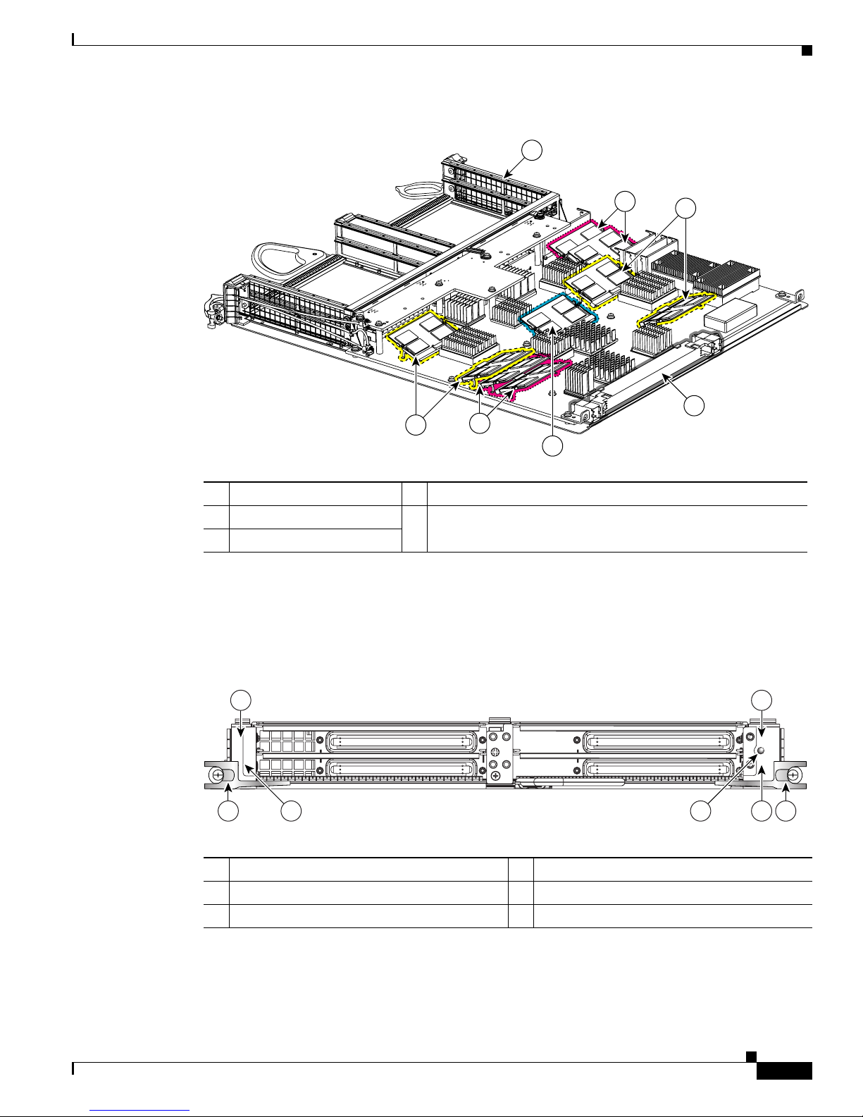
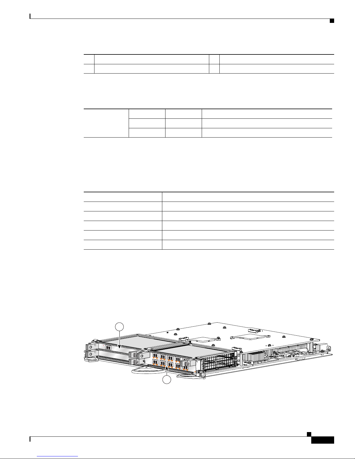
Cisco 12000 SIP-400 Board Components
The main Cisco 12000 SIP-400 board components are shown in Figure 1-1. Board reference designators
are indicated after the board component name.
Cisco 12000
SIP-401
12000-SIP-401 12.0(32)S 1.0
Cisco 12000
SIP-501
12000-SIP-501 12.0(32)S 1.0
Cisco 12000
SIP-601
12000-SIP-601 12.0(32)S 1.0
Table 1-3 SIP Hardware and Software Compatibility
SIP Part Number
Minimum Cisco IOS Software
Release
Minimum Hardware
Revision
Page 25
1-5
Cisco 12000 Series Router SIP and SPA Hardware Installation Guide
Release 12.0(32)SY1, OL-8831-01, Rev. G6, July 19, 2007
Chapter 1 Overview: Cisco 12000 Series Router SPA Interface Processors
Cisco 12000 SIP-400 Overview
Figure 1-1 Cisco 12000 SIP-400 Board—Rear View
Cisco 12000 SIP-400 LEDs
The Cisco 12000 SIP-400 has one LED, as shown in Figure 1-2.
Figure 1-2 Cisco 12000 SIP-400 Face Plate
The Cisco 12000 SIP-400 LEDs are described in Ta bl e 1 -4 .
1 SPA enclosure 4 Four packet memory SODIMM sockets (not field serviceable)
2 Backplane connector 5 Four TLU/PLU memory SODIMM sockets (not field
serviceable)
3 Route memory SODIMM
122079
1
5
5
4
4
3
2
1 SPA subslot 0 4 SPA subslot 3
2 SPA subslot 1 5 Ejector Levers
3 SPA subslot 2 6 Status LED
1
3
0
2
12000-SIP-400
122093
STATUS
5 54
1 2
3 6
Page 26
1-6
Cisco 12000 Series Router SIP and SPA Hardware Installation Guide
Release 12.0(32)SY1, OL-8831-01, Rev. G6, July 19, 2007
Chapter 1 Overview: Cisco 12000 Series Router SPA Interface Processors
Cisco 12000 SIP-400 Overview
Cisco 12000 SIP-400 Physical Specifications
The Cisco 12000 SIP-400 physical specifications are shown in the following table.
SPA Slot Numbering on the Cisco 12000 SIP-400
The Cisco 12000 SIP-400 accepts 4 single-width, single-height SPAs.
Figure 1-3 shows a Cisco 12000 SIP-400 with 4 SPAs installed. The top leftmost SPA slot is subslot 0;
the top rightmost SPA slot is subslot 1; the bottom leftmost SPA slot is subslot 2; the bottom rightmost
SPA slot is subslot 3.
Figure 1-3 Cisco 12000 SIP-400 with SPAs Installed
Table 1-4 Cisco 12000 SIP-400 LED
LED Label Color State Meaning
Status Yellow On IOS is loaded and SIP is ready to be enabled.
Green On SIP is active.
Table 1-5 Cisco 12000 SIP-400 Physical Specifications
Description Specifications
Physical dimensions Occupies one line card slot on a Cisco 12000 Series Router
Shipping weight 10 kg
Operating temperature 32 to 104°F (0 to 40°C)
Relative humidity 10 to 90 percent, noncondensing
Storage temperature –4 to 149°F (–20 to 65°C)
122066
12000-SIP-400
1
3
2
0
STATUS
C/A
TX
RX
1
STATUS
SPA-4XT3/E3
0
A/L
C/A
TX
RX
A/L
C
/A
TX
RX
2
A/L
C/A
TX
RX
3
A/L
C/A
TX
RX
1
STATUS
SPA-4XT3/E3
0
A/L
C/A
TX
RX
A/L
C/A
TX
RX
2
A/L
C/A
TX
RX
3
A/L
C/A
TX
RX
1
STATUS
SPA-4XT3/E3
0
A/L
C/A
TX
RX
A/L
C/A
TX
RX
2
A/L
C/A
TX
R
X
3
A/L
C/A
TX
RX
1
STATUS
SPA-4XT3/E3
0
A/L
C/A
TX
RX
A/L
C/A
TX
RX
2
A/L
C/A
TX
R
X
3
A/L
1
2
3
4
Page 27
1-7
Cisco 12000 Series Router SIP and SPA Hardware Installation Guide
Release 12.0(32)SY1, OL-8831-01, Rev. G6, July 19, 2007
Chapter 1 Overview: Cisco 12000 Series Router SPA Interface Processors
Cisco 12000 SIP-400 Overview
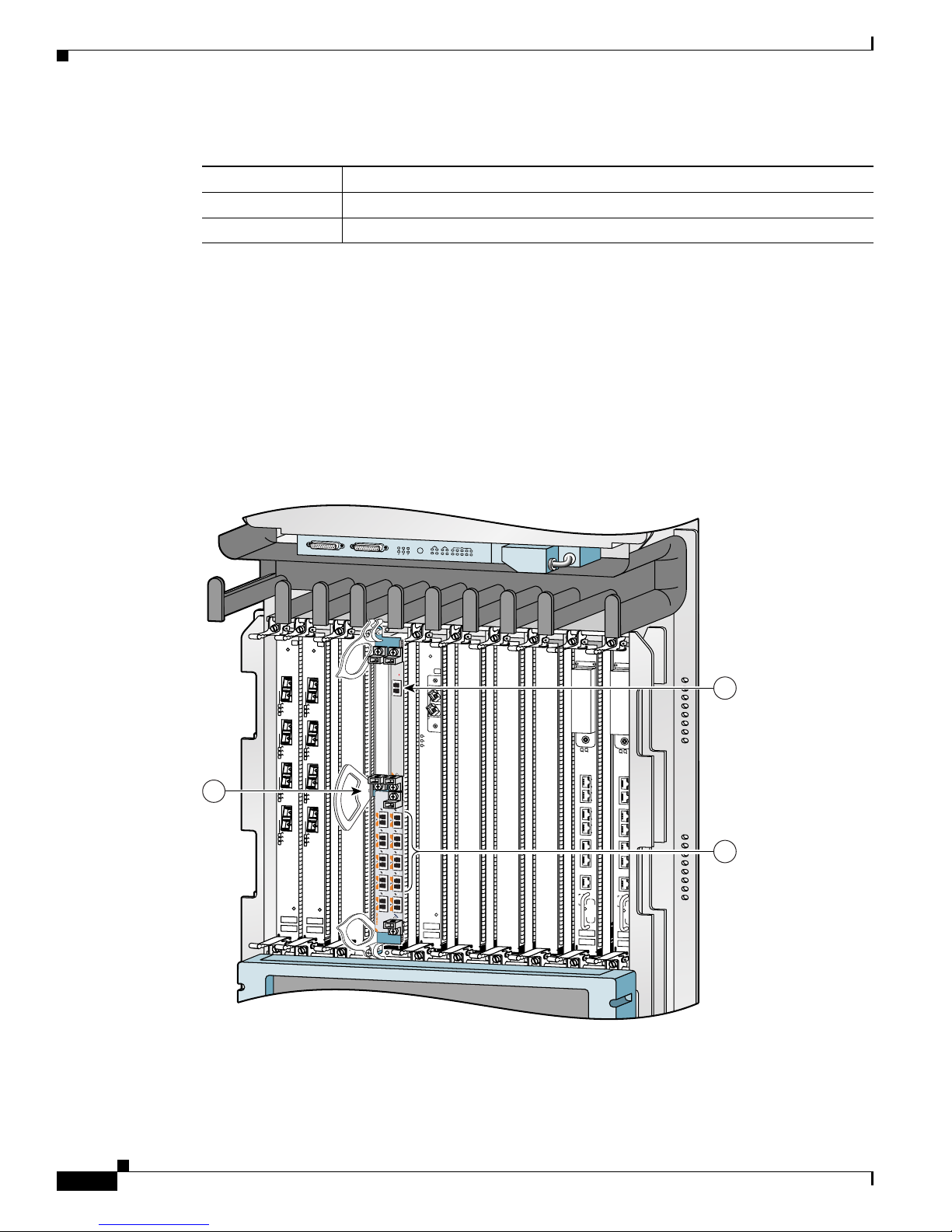
SPA Interface Addresses on the Cisco 12000 SIP-400
A Cisco 12000 Series Router identifies a SPA interface address by its SIP slot number, SPA subslot, and
port number on the SPA, in the format slot/subslot/port. Subslots and ports are numbered starting from
0, so each Cisco 12000 SIP-400 has four subslots. A 4-port SPA would have ports 0 to 3. For example,
the interface address of the second port on a 4-port SPA located in the first SIP subslot, where the SIP is
inserted into router line card slot 6 is 6/0/1.
Figure 1-4 Cisco 12000 Series Router with Cisco 12000 SIP-400 Installed
1 SPA subslot 0 3 SPA subslot 2
2 SPA subslot 1 4 SPA subslot 3
1 Router slot number 6 4 SPA subslot 2 with ports 6/2/0 to 6/2/3
2 SPA subslot 0 with ports 6/0/0 to 6/0/3 5 SPA subslot 3 with ports 6/3/0 to 6/3/3
3 SPA subslot 1 with ports 6/1/0 to 6/1/3
ACTIVE
0
CARRIER
RX PKT
ACTIVE
1
CARRIER
RX PKT
ACTIVE
2
CARRIER
RX PKT
ACTIVE
3
CARRIER
RX PKT
Q OC-3/STM-POS
ACTIVE
0
CARRIER
RX PKT
ACTIVE
1
CARRIER
RX PKT
ACTIVE
2
CARRIER
RX PKT
ACTIVE
3
CARRIER
RX PKT
Q OC-3/STM-POS
ACTIVE
CARRIER
RX PKT
OC-48/STM-16-SCPOS
EJECT
ACT
SIG
AC
T
SIG
SLOT-1
SLOT-0
CONSOLE ETH 2AUX
RESET
PERFORMANCE ROUTE PROCESSOR 2
BITS 1BITS 0
DATA
LINK
DATA
LINK
ETH 1ETH 0
EJECT
ACT
SIG
ACT
SIG
SLOT-1
SLOT-0
CONSOLE ETH 2AUX
RESET
PERFORMANCE ROUTE PROCESSOR 2
BITS 1BITS 0
DATA
LINK
DATA
LIN
K
ETH 1ETH 0
ALARM A
ALARM B
A
A
MBUS
M
IN
O
R
B
FAIL
ENABLE
M
A
J
O
R
C
R
I
T
IC
A
L
B
0
CSC
1
0
SFC
1
2
3
4
129102
STATUS
1
12000-SIP-600
0
S
T
A
T
U
S
ACTIVE/LINK
SPA-1XTENGE-XFP-A
C/A
TX
RX
1
STA
TU
S
SPA-4XCT3/DS0
0
A/L
C/A
TX
R
X
A/L
C/A
TX
RX
2
A/L
C/A
TX
RX
3
A/L
C/A
TX
RX
1
ST
A
T
US
SPA-4XCT3/DS0
0
A/L
C/A
TX
RX
A/L
C/A
TX
RX
2
A/L
C/A
TX
RX
3
A/L
C/A
TX
RX
1
S
T
AT
U
S
SPA-4XCT3/DS0
0
A/L
C/A
TX
RX
A/L
C/A
TX
RX
2
A/L
C/A
TX
RX
3
A/L
C/A
TX
RX
1
STA
T
U
S
SPA-4XCT3/DS0
0
A/L
C/A
TX
RX
A/L
C/A
TX
RX
2
A/L
C/A
TX
RX
3
A/L
4
2
1
5
3
Page 28
1-8
Cisco 12000 Series Router SIP and SPA Hardware Installation Guide
Release 12.0(32)SY1, OL-8831-01, Rev. G6, July 19, 2007
Chapter 1 Overview: Cisco 12000 Series Router SPA Interface Processors
Cisco 12000 SIP-600 Overview
Cisco 12000 SIP-600 Overview
The following sections describe the Cisco 12000 SIP-600:
• Cisco 12000 SIP-600 Board Components, page 1-8
• Cisco 12000 SIP-600 LEDs, page 1-8
• Cisco 12000 SIP-600 Physical Specifications, page 1-9
• SPA Subslot Numbering on the Cisco 12000 SIP-600, page 1-9
• SPA Interface Addresses on the Cisco 12000 SIP-600, page 1-10
Cisco 12000 SIP-600 Board Components
The main Cisco 12000 SIP-600 board components are shown in Figure 1-5.
Figure 1-5 Cisco 12000 SIP-600 Board—Rear View
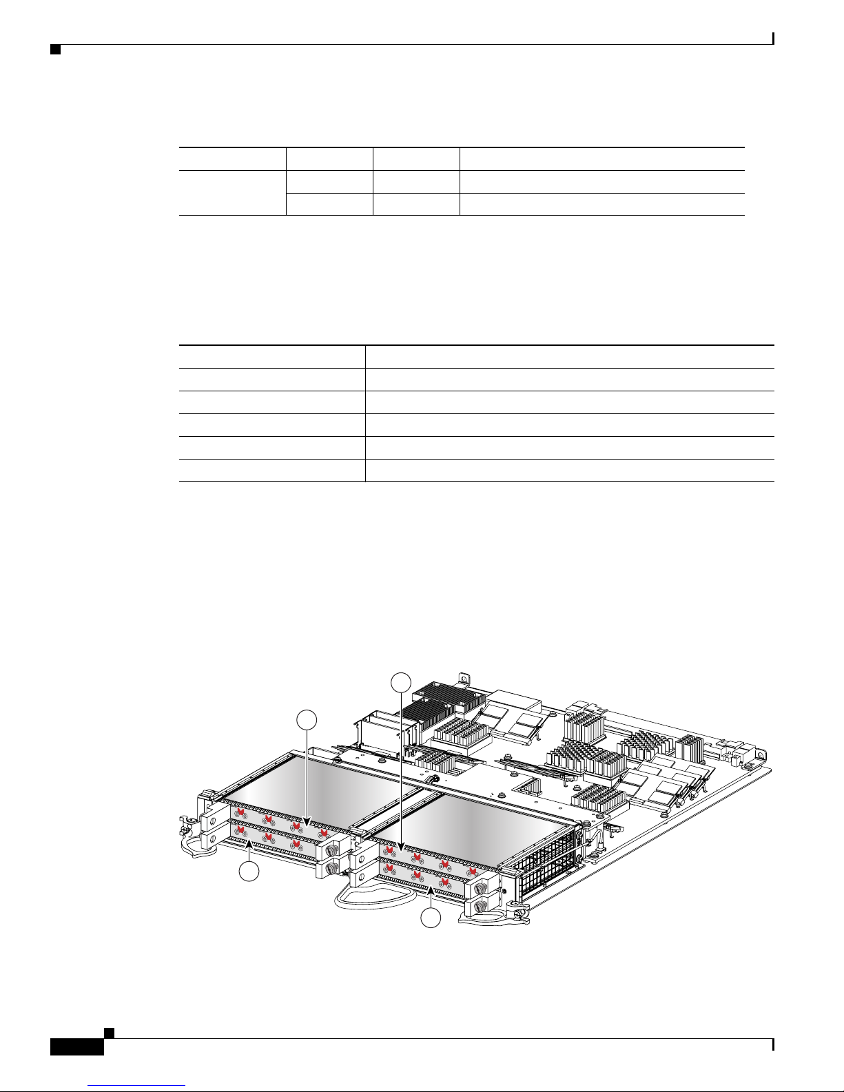
Cisco 12000 SIP-600 LEDs
The Cisco 12000 SIP-600 supports 2 single-width, double-height SPAs, 2 single-width, single-height
SPAs, or 1 dual-width, double-height SPA. The Cisco 12000 SIP-600 face plate has one Status LED.
Figure 1-6 shows the Cisco 12000 SIP-600 face plate with 2 single-width, single-height SPAs.
Figure 1-6 Cisco 12000 SIP-600 Face Plate
1 SPA enclosure 2 Backplane connector
122074
1
2
STATUS
1
0
12000-SIP-600
116871
3
1 2
3
4
Page 29
1-9
Cisco 12000 Series Router SIP and SPA Hardware Installation Guide
Release 12.0(32)SY1, OL-8831-01, Rev. G6, July 19, 2007
Chapter 1 Overview: Cisco 12000 Series Router SPA Interface Processors
Cisco 12000 SIP-600 Overview
The Cisco 12000 SIP-600 LEDs are described in Ta bl e 1 -6 .
Cisco 12000 SIP-600 Physical Specifications
The Cisco 12000 SIP-600 physical specifications are shown in the following table.
SPA Subslot Numbering on the Cisco 12000 SIP-600
The Cisco 12000 SIP-600 accepts 2 single-width SPAs or 1 dual-width SPA.
Figure 1-7 shows a Cisco 12000 SIP-600 with 2 SPAs installed. The left SPA slot is subslot 0 and the
right SPA slot is subslot 1. If one dual-width SPA is installed, it is recognized as being in subslot 0.
Figure 1-7 Subslot Locations for the 1-Port 10-Gigabit Ethernet SPA
1 SPA subslot 0 3 Ejector Levers
2 SPA subslot 1 4 Status LED
Table 1-6 Cisco 12000 SIP-600 LEDs
LED Label Color State Meaning
Status Yellow On SIP is powered and IOS is loading.
Green On SIP is active.
Table 1-7 Cisco 12000 SIP-600 Physical Specifications
Description Specifications
Physical dimensions Occupies one line card slot on a Cisco 12000 Series Router
Shipping weight 10kg
Operating temperature 32 to 104°F (0 to 40°C)
Relative humidity 10 to 90 percent, noncondensing
Storage temperature –4 to 149°F (–20 to 65°C)
12000-SIP-600
0
116872
STATUS
SPA-1XTENGE-XFP-A
ACTIVE/LINK
SPA10X1GE-A
STATUS
4
9
3
8
2
7
1
6
0
5
A/L
A/L
A/L
A/L
A/L
A/L
A/L
A/L
A/L
A/L
1
2
Page 30
1-10
Cisco 12000 Series Router SIP and SPA Hardware Installation Guide
Release 12.0(32)SY1, OL-8831-01, Rev. G6, July 19, 2007
Chapter 1 Overview: Cisco 12000 Series Router SPA Interface Processors
Cisco 12000 SIP-600 Overview
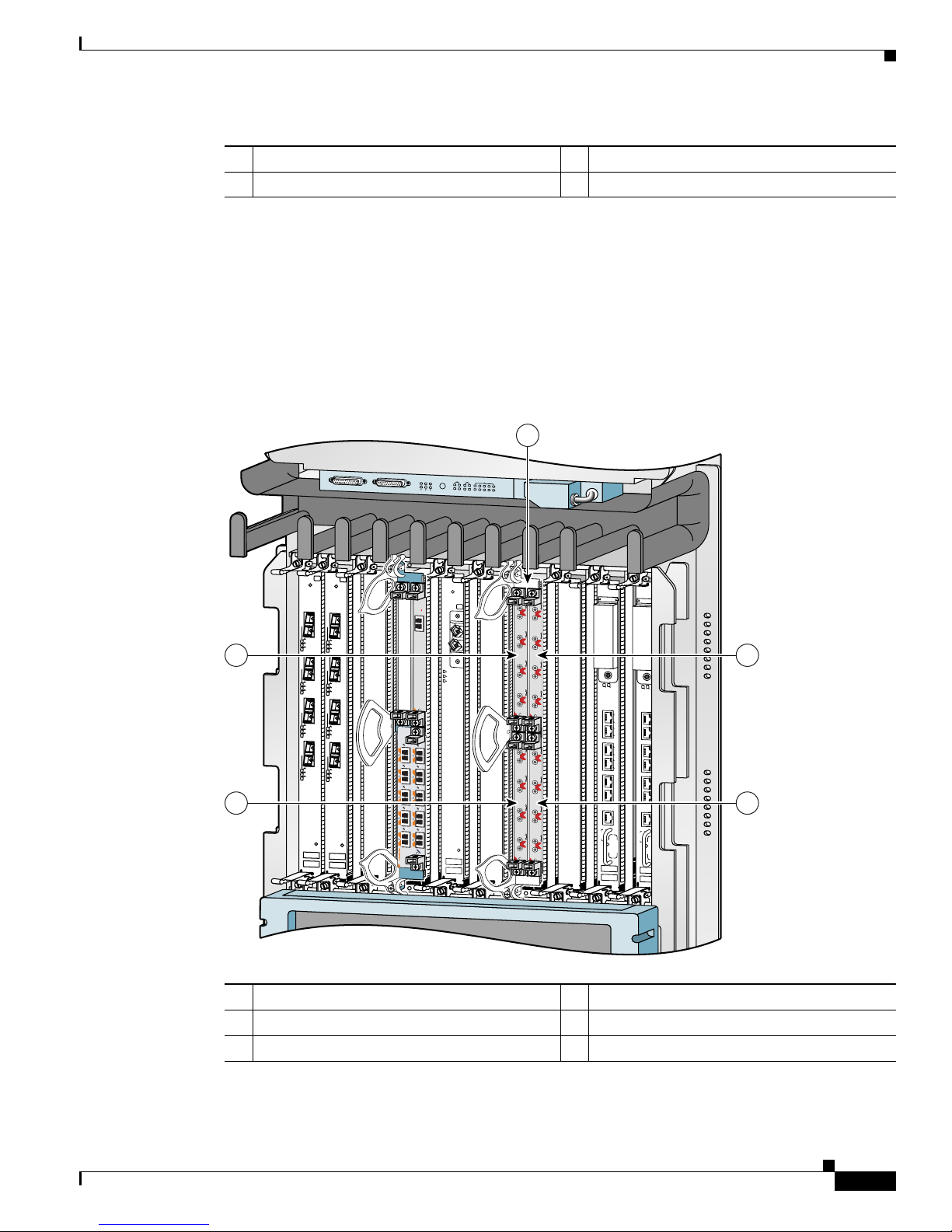
SPA Interface Addresses on the Cisco 12000 SIP-600
A Cisco 12000 Series Router identifies a SPA interface address by its SIP slot number, SPA subslot, and
port number on the SPA, in the format slot/subslot/port. Subslots and ports are numbered starting from
0, so each Cisco 12000 SIP-600 has two subslots 0 (left) and 1 (right). For example, the interface address
of a 1-port SPA located in the second SIP subslot, where the SIP is inserted into router line card slot 3
is 3/1/0. Figure 1-8 shows the slot, subslot, and port locations for the 1-Port 10-Gigabit Ethernet SPA
and the 10-Port Gigabit Ethernet SPA.
Figure 1-8 Slot, Subslot, and Port Locations for the 1-Port 10-Gigabit Ethernet SPA and the 10-Port
Gigabit Ethernet SPA.
Table 1-8 Subslot Locations for the 1-Port 10-Gigabit Ethernet SPA
Call Out Number Description
1Subslot 0
2Subslot 1
ACTIVE
0
CARRIER
RX PKT
ACTIVE
1
CARRIER
RX PKT
ACTIVE
2
CARRIER
RX PKT
ACTIVE
3
CARRIER
RX PKT
Q OC-3/STM-POS
ACTIVE
0
CARRIER
RX PKT
ACTIVE
1
CARRIER
RX PKT
ACTIVE
2
CARRIER
RX PKT
ACTIVE
3
CARRIER
RX PKT
Q OC-3/STM-POS
ACTIVE
CARRIER
RX PKT
OC-48/STM-16-SCPOS
EJECT
ACT
SIG
ACT
SIG
SLOT-1
SLO
T-0
CONSOLE ETH 2AUX
RESET
PERFORMANCE ROUTE PROCESSOR 2
BITS 1BITS 0
DATA
LINK
DATA
LINK
ETH 1ETH 0
EJECT
ACT
SIG
ACT
S
IG
SLOT-1
SLO
T-0
CONSOLE ETH 2AUX
RESET
PERFORMANCE ROUTE PROCESSOR 2
BITS 1BITS 0
DATA
LINK
DATA
LINK
ETH 1ETH 0
ALARM A
ALARM B
A
A
MBUS
M
IN
O
R
B
FAIL
ENABLE
M
A
J
O
R
C
R
IT
I
C
A
L
B
0
CSC
1
0
SFC
1
2
3
4
129009
ST
A
T
U
S
ACTIVE/LINK
SPA-1XTENGE-XFP-A
1
2
3
Page 31

1-11
Cisco 12000 Series Router SIP and SPA Hardware Installation Guide
Release 12.0(32)SY1, OL-8831-01, Rev. G6, July 19, 2007
Chapter 1 Overview: Cisco 12000 Series Router SPA Interface Processors
Cisco 12000 SIP-401 Overview
Cisco 12000 SIP-401 Overview
The following sections describe the Cisco 12000 SIP-401:
• Cisco 12000 SIP-401 Board Components, page 1-11
• Cisco 12000 SIP-401 LEDs, page 1-11
• Cisco 12000 SIP-401 Physical Specifications, page 1-12
• SPA Slot Numbering on the Cisco 12000 SIP-401, page 1-12
• SPA Interface Addresses on the Cisco 12000 SIP-401, page 1-13
Cisco 12000 SIP-401 Board Components
The main Cisco 12000 SIP-501 board components are shown in Figure 1-9.
Figure 1-9 Cisco 12000 SIP-401 Board—Rear View
Cisco 12000 SIP-401 LEDs
The Cisco 12000 SIP-401 has two LEDs, as shown in Figure 1-10.
Table 1-9 Slot and Port Locations for the 1-Port 10-Gigabit Ethernet SPA
Call Out Number Description
1Slot 3
2 Subslot 0, Port 3/0/0
3 Subslot 1, Ports 3/1/0 to 3/1/9
1 SPA enclosure 2 Backplane connector
122074
1
2
Page 32

1-12
Cisco 12000 Series Router SIP and SPA Hardware Installation Guide
Release 12.0(32)SY1, OL-8831-01, Rev. G6, July 19, 2007
Chapter 1 Overview: Cisco 12000 Series Router SPA Interface Processors
Cisco 12000 SIP-401 Overview
Figure 1-10 Cisco 12000 SIP-401 Face Plate
The Cisco 12000 SIP-401 LEDs are described in Ta ble 1-1 0 .
Cisco 12000 SIP-401 Physical Specifications
The Cisco 12000 SIP-401 physical specifications are shown in the following table.
SPA Slot Numbering on the Cisco 12000 SIP-401
The Cisco 12000 SIP-401 accepts 4 single-width, single-height SPAs.
1 SPA subslot 0 5 Ejector Levers
2 SPA subslot 1 6 Status LED
3 SPA subslot 2 7 Rate LED
4 SPA subslot 3
1
3
0
2
12000-SIP-400
158211
RATE
5 54
1 2
3 7
6
STATUS
Table 1-10 Cisco 12000 SIP-401 LED
LED Label Color State Meaning
Status Yellow On IOS is loaded and SIP is ready to be enabled.
Green On SIP is active.
Rate Off Off SIP is SIP-401 or SIP-501.
Green On SIP is SIP-601.
Table 1-11 Cisco 12000 SIP-401 Physical Specifications
Description Specifications
Physical dimensions Occupies one line card slot on a Cisco 12000 Series Router
Shipping weight 10 kg
Operating temperature 32 to 104°F (0 to 40°C)
Relative humidity 10 to 90 percent, noncondensing
Storage temperature –4 to 149°F (–20 to 65°C)
Page 33

1-13
Cisco 12000 Series Router SIP and SPA Hardware Installation Guide
Release 12.0(32)SY1, OL-8831-01, Rev. G6, July 19, 2007
Chapter 1 Overview: Cisco 12000 Series Router SPA Interface Processors
Cisco 12000 SIP-401 Overview
Figure 1-11 shows a Cisco 12000 SIP-401 with 4 SPAs installed. The top leftmost SPA slot is subslot 0;
the top rightmost SPA slot is subslot 1; the bottom leftmost SPA slot is subslot 2; the bottom rightmost
SPA slot is subslot 3.
Figure 1-11 Cisco 12000 SIP-401 with SPAs Installed
SPA Interface Addresses on the Cisco 12000 SIP-401
A Cisco 12000 Series Router identifies a SPA interface address by its SIP slot number, SPA subslot, and
port number on the SPA, in the format slot/subslot/port. Subslots and ports are numbered starting from
0, so each Cisco 12000 SIP-401 has four subslots. A 4-port SPA would have ports 0 to 3. For example,
the interface address of the second port on a 4-port SPA located in the first SIP subslot, where the SIP is
inserted into router line card slot 6 is 6/0/1.
1 SPA subslot 0 3 SPA subslot 2
2 SPA subslot 1 4 SPA subslot 3
122066
12000-SIP-400
1
3
2
0
STATUS
C/A
TX
RX
1
STATUS
SPA-4XT3/E3
0
A/L
C/A
TX
RX
A/L
C
/A
TX
RX
2
A
/L
C/A
TX
RX
3
A/L
C/A
TX
R
X
1
STATUS
SPA-4XT3/E3
0
A/L
C/A
TX
RX
A/L
C/A
TX
RX
2
A/L
C/A
TX
RX
3
A/L
C/A
TX
R
X
1
STATUS
SPA-4XT3/E3
0
A/L
C/A
TX
RX
A/L
C/A
TX
RX
2
A/L
C/A
TX
RX
3
A/L
C/A
TX
R
X
1
STATUS
SPA-4XT3/E3
0
A/L
C/A
TX
RX
A/L
C/A
TX
RX
2
A/L
C/A
TX
RX
3
A/L
1
2
3
4
Page 34

1-14
Cisco 12000 Series Router SIP and SPA Hardware Installation Guide
Release 12.0(32)SY1, OL-8831-01, Rev. G6, July 19, 2007
Chapter 1 Overview: Cisco 12000 Series Router SPA Interface Processors
Cisco 12000 SIP-501 Overview
Figure 1-12 Cisco 12000 Series Router with Cisco 12000 SIP-401 Installed
Cisco 12000 SIP-501 Overview
The following sections describe the Cisco 12000 SIP-501:
• Cisco 12000 SIP-501 Board Components, page 1-15
• Cisco 12000 SIP-501 LEDs, page 1-15
• Cisco 12000 SIP-501 Physical Specifications, page 1-16
• SPA Subslot Numbering on the Cisco 12000 SIP-501, page 1-16
• SPA Interface Addresses on the Cisco 12000 SIP-501, page 1-17
1 Router slot number 6 4 SPA subslot 2 with ports 6/2/0 to 6/2/3
2 SPA subslot 0 with ports 6/0/0 to 6/0/3 5 SPA subslot 3 with ports 6/3/0 to 6/3/3
3 SPA subslot 1 with ports 6/1/0 to 6/1/3
ACTIVE
0
CARRIER
RX PKT
ACTIVE
1
CARRIER
RX PKT
ACTIVE
2
CARRIER
RX PKT
ACTIVE
3
CARRIER
RX PKT
Q OC-3/STM-POS
ACTIVE
0
CARRIER
RX PKT
ACTIVE
1
CARRIER
RX PKT
ACTIVE
2
CARRIER
RX PKT
ACTIVE
3
CARRIER
RX PKT
Q OC-3/STM-POS
ACTIVE
CARRIER
RX PKT
OC-48/STM-16-SCPOS
EJECT
ACT
SIG
ACT
SIG
SLOT-1
SLO
T-0
CONSOLE ETH 2AUX
RESET
PERFORMANCE ROUTE PROCESSOR 2
BITS 1BITS 0
DATA
LINK
DATA
LINK
ETH 1ETH 0
EJECT
ACT
SIG
ACT
SIG
SLOT-1
SLOT-0
CONSOLE ETH 2AUX
RESET
PERFORMANCE ROUTE PROCESSOR 2
BITS 1BITS 0
DATA
LINK
DATA
LINK
ETH 1ETH 0
ALARM A
ALARM B
A
A
MB
US
M
I
N
O
R
B
FAIL
ENABLE
M
A
J
O
R
C
R
I
T
I
C
A
L
B
0
CSC
1
0
SFC
1
2
3
4
129102
STATUS
1
12000-SIP-600
0
S
T
A
T
U
S
ACTIVE/LINK
SPA-1XTENGE-XFP-A
C/A
TX
RX
1
S
T
A
TU
S
SPA-4XCT3/DS0
0
A
/L
C/A
TX
RX
A/L
C
/A
T
X
RX
2
A/L
C/A
TX
RX
3
A/L
C/A
TX
RX
1
S
T
A
T
U
S
SPA-4XCT3/DS0
0
A/L
C/A
TX
RX
A/L
C
/A
TX
RX
2
A/L
C/A
TX
RX
3
A/L
C/A
TX
RX
1
S
TA
T
U
S
SPA-4XCT3/DS0
0
A/L
C/A
TX
RX
A/L
C/A
TX
R
X
2
A/L
C/A
T
X
RX
3
A/L
C/A
TX
RX
1
ST
A
T
U
S
SPA-4XCT3/DS0
0
A/L
C/A
TX
R
X
A/L
C/A
TX
RX
2
A/L
C/A
TX
RX
3
A/L
4
2
1
5
3
Page 35

1-15
Cisco 12000 Series Router SIP and SPA Hardware Installation Guide
Release 12.0(32)SY1, OL-8831-01, Rev. G6, July 19, 2007
Chapter 1 Overview: Cisco 12000 Series Router SPA Interface Processors
Cisco 12000 SIP-501 Overview
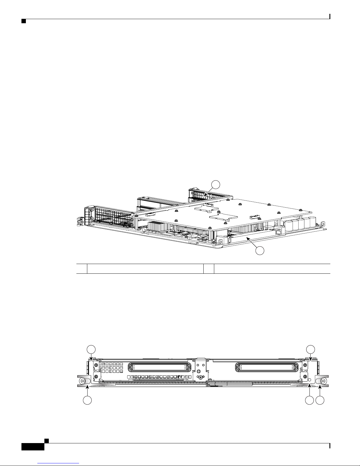
Cisco 12000 SIP-501 Board Components
The main Cisco 12000 SIP-501 board components are shown in Figure 1-13.
Figure 1-13 Cisco 12000 SIP-501 Board—Rear View
Cisco 12000 SIP-501 LEDs
The Cisco 12000 SIP-501 supports 4 single-height SPAs (the aggregate throughput should not exceed 2
full-rate SPAs); 2 double-height SPAs; 1 dual-width, double-height SPA, or a combination of
single-height and double-height SPAs.
The interconnect between a SIP and a SPA can operate at either 2.5Gbps or 10Gbps. If the maximum
capacity of a SPA is greater than 2.5Gbps the interconnect operates at 10Gbps and the SPA is a "full-rate"
SPA. If the maximum capacity of a SPA is 2.5Gbps or less the interconnect operates at 2.5Gbps and the
SPA is a "quarter-rate" SPA. The Cisco 12000 SIP-501 can support up to two full-rate SPAs, or one
full-rate and three quarter-rate SPAs or four quarter-rate SPAs.
The Cisco 12000 SIP-501 face plate has one Status LED. Figure 1-14 shows the Cisco 12000 SIP-501
face plate with 4 single-width, single-height SPAs.
Figure 1-14 Cisco 12000 SIP-501 Face Plate
1 SPA enclosure 2 Backplane connector
122074
1
2
1 SPA subslot 0 5 Ejector Levers
1
3
0
2
12000-SIP-400
158211
RATE
5 54
1 2
3 7
6
STATUS
Page 36

1-16
Cisco 12000 Series Router SIP and SPA Hardware Installation Guide
Release 12.0(32)SY1, OL-8831-01, Rev. G6, July 19, 2007
Chapter 1 Overview: Cisco 12000 Series Router SPA Interface Processors
Cisco 12000 SIP-501 Overview
The Cisco 12000 SIP-501 LEDs are described in Ta ble 1-1 2 .
Cisco 12000 SIP-501 Physical Specifications
The Cisco 12000 SIP-501 physical specifications are shown in the following table.
SPA Subslot Numbering on the Cisco 12000 SIP-501
The Cisco 12000 SIP-501 accepts up to 4 single-width SPAs or 1 dual-width SPA.
Figure 1-15 shows a Cisco 12000 SIP-501 with 2 SPAs installed. The left SPA slot is subslot 0 and the
right SPA slot is subslot 1. If one dual-width SPA is installed, it is recognized as being in subslot 0.
Figure 1-15 Subslot Locations for the 1-Port 10-Gigabit Ethernet SPA
2 SPA subslot 1 6 Status LED
3 SPA subslot 2 7 Rate LED
4 SPA subslot 3
Table 1-12 Cisco 12000 SIP-501 LEDs
LED Label Color State Meaning
Status Yellow On SIP is powered and IOS is loading.
Green On SIP is active.
Rate Off Off SIP is SIP-401 or SIP-501.
Green On SIP is SIP-601.
Table 1-13 Cisco 12000 SIP-501 Physical Specifications
Description Specifications
Physical dimensions Occupies one line card slot on a Cisco 12000 Series Router
Shipping weight 10kg
Operating temperature 32 to 104°F (0 to 40°C)
Relative humidity 10 to 90 percent, noncondensing
Storage temperature –4 to 149°F (–20 to 65°C)
12000-SIP-600
0
116872
STATUS
SPA-1XTENGE-XFP-A
ACTIVE/LINK
SPA10X1GE-A
STATUS
4
9
3
8
2
7
1
6
0
5
A/L
A/L
A/L
A/L
A/L
A/L
A/L
A/L
A/L
A/L
1
2
Page 37

1-17
Cisco 12000 Series Router SIP and SPA Hardware Installation Guide
Release 12.0(32)SY1, OL-8831-01, Rev. G6, July 19, 2007
Chapter 1 Overview: Cisco 12000 Series Router SPA Interface Processors
Cisco 12000 SIP-501 Overview
SPA Interface Addresses on the Cisco 12000 SIP-501
A Cisco 12000 Series Router identifies a SPA interface address by its SIP slot number, SPA subslot, and
port number on the SPA, in the format slot/subslot/port. Subslots and ports are numbered starting from
0, so each Cisco 12000 SIP-601 has two subslots 0 (left) and 1 (right). For example, the interface address
of a 1-port SPA located in the second SIP subslot, where the SIP is inserted into router line card slot 3
is 3/1/0. Figure 1-16 shows the slot, subslot, and port locations for the 1-Port 10-Gigabit Ethernet SPA
and the 10-Port Gigabit Ethernet SPA.
Figure 1-16 Slot, Subslot, and Port Locations for the 1-Port 10-Gigabit Ethernet SPA and the 10-Port
Gigabit Ethernet SPA.
Table 1-14 Subslot Locations for the 1-Port 10-Gigabit Ethernet SPA
Call Out Number Description
1Subslot 0
2Subslot 1
ACTIVE
0
CARRIER
RX PKT
ACTIVE
1
CARRIER
RX PKT
ACTIVE
2
CARRIER
RX PKT
ACTIVE
3
CARRIER
RX PKT
Q OC-3/STM-POS
ACTIVE
0
CARRIER
RX PKT
ACTIVE
1
CARRIER
RX PKT
ACTIVE
2
CARRIER
RX PKT
ACTIVE
3
CARRIER
RX PKT
Q OC-3/STM-POS
ACTIVE
CARRIER
RX PKT
OC-48/STM-16-SCPOS
EJECT
ACT
SIG
ACT
SIG
SLOT-1
SLOT-0
CONSOLE ETH 2AUX
RESET
PERFORMANCE ROUTE PROCESSOR 2
BITS 1BITS 0
DAT
A
LINK
DATA
LIN
K
ETH 1ETH 0
EJECT
ACT
SIG
A
CT
SIG
SLOT-1
SLOT-0
CONSOLE ETH 2AUX
RESET
PERFORMANCE ROUTE PROCESSOR 2
BITS 1BITS 0
DATA
LINK
DATA
LINK
ETH 1ETH 0
ALARM A
ALARM B
A
A
MBUS
M
I
N
O
R
B
FAIL
ENABLE
M
A
J
O
R
C
R
IT
IC
A
L
B
0
CSC
1
0
SFC
1
2
3
4
129009
S
TA
T
U
S
ACTIVE/LINK
SPA-1XTENGE-XFP-A
1
2
3
Page 38

1-18
Cisco 12000 Series Router SIP and SPA Hardware Installation Guide
Release 12.0(32)SY1, OL-8831-01, Rev. G6, July 19, 2007
Chapter 1 Overview: Cisco 12000 Series Router SPA Interface Processors
Cisco 12000 SIP-601 Overview
Cisco 12000 SIP-601 Overview
The following sections describe the Cisco 12000 SIP-601:
• Cisco 12000 SIP-601 Board Components, page 1-18
• Cisco 12000 SIP-601 LEDs, page 1-18
• Cisco 12000 SIP-601 Physical Specifications, page 1-19
• SPA Subslot Numbering on the Cisco 12000 SIP-601, page 1-20
• SPA Interface Addresses on the Cisco 12000 SIP-601, page 1-20
Cisco 12000 SIP-601 Board Components
The main Cisco 12000 SIP-601 board components are shown in Figure 1-17.
Figure 1-17 Cisco 12000 SIP-601 Board—Rear View
Cisco 12000 SIP-601 LEDs
The Cisco 12000 SIP-601 supports 4 single-height SPAs (the aggregate throughput should not exceed 2
full-rate SPAs); 2 double-height SPAs; 1 dual-width, double-height SPA, or a combination of
single-height and double-height SPAs.
Table 1-15 Slot and Port Locations for the 1-Port 10-Gigabit Ethernet SPA
Call Out Number Description
1Slot 3
2 Subslot 0, Port 3/0/0
3 Subslot 1, Ports 3/1/0 to 3/1/9
1 SPA enclosure 2 Backplane connector
122074
1
2
Page 39

1-19
Cisco 12000 Series Router SIP and SPA Hardware Installation Guide
Release 12.0(32)SY1, OL-8831-01, Rev. G6, July 19, 2007
Chapter 1 Overview: Cisco 12000 Series Router SPA Interface Processors
Cisco 12000 SIP-601 Overview
The interconnect between a SIP and a SPA can operate at either 2.5Gbps or 10Gbps. If the maximum
capacity of a SPA is greater than 2.5Gbps the interconnect operates at 10Gbps and the SPA is a "full-rate"
SPA. If the maximum capacity of a SPA is 2.5Gbps or less the interconnect operates at 2.5Gbps and the
SPA is a "quarter-rate" SPA. The Cisco 12000 SIP-601 can support up to two full-rate SPAs, or one
full-rate and three quarter-rate SPAs or four quarter-rate SPAs.
The Cisco 12000 SIP-601 face plate has one Status LED. Figure 1-18 shows the Cisco 12000 SIP-601
face plate with 2 single-width, single-height SPAs.
Figure 1-18 Cisco 12000 SIP-601 Face Plate
The Cisco 12000 SIP-601 LEDs are described in Ta bl e 1 -1 6.
Cisco 12000 SIP-601 Physical Specifications
The Cisco 12000 SIP-601 physical specifications are shown in the following table.
1 SPA subslot 0 5 Ejector Levers
2 SPA subslot 1 6 Status LED
3 SPA subslot 2 7 Rate LED
4 SPA subslot 3
1
3
0
2
12000-SIP-400
158211
RATE
5 54
1 2
3 7
6
STATUS
Table 1-16 Cisco 12000 SIP-601 LEDs
LED Label Color State Meaning
Status Yellow On SIP is powered and IOS is loading.
Green On SIP is active.
Rate Off Off SIP is SIP-401 or SIP-501.
Green On SIP is SIP-601.
Table 1-17 Cisco 12000 SIP-601 Physical Specifications
Description Specifications
Physical dimensions Occupies one line card slot on a Cisco 12000 Series Router
Shipping weight 10kg
Operating temperature 32 to 104°F (0 to 40°C)
Page 40

1-20
Cisco 12000 Series Router SIP and SPA Hardware Installation Guide
Release 12.0(32)SY1, OL-8831-01, Rev. G6, July 19, 2007
Chapter 1 Overview: Cisco 12000 Series Router SPA Interface Processors
Cisco 12000 SIP-601 Overview
SPA Subslot Numbering on the Cisco 12000 SIP-601
The Cisco 12000 SIP-601 accepts 4 single-height SPAs (the aggregate throughput should not exceed 2
full-rate SPAs); 2 double-height SPAs; 1 dual-width, double-height SPA, or a combination of
single-height and double-height SPAs.
Figure 1-19 shows a Cisco 12000 SIP-601 with 2 SPAs installed. The left SPA slot is subslot 0 and the
right SPA slot is subslot 1. If one dual-width SPA is installed, it is recognized as being in subslot 0.
Figure 1-19 Subslot Locations for the 1-Port 10-Gigabit Ethernet SPA
SPA Interface Addresses on the Cisco 12000 SIP-601
A Cisco 12000 Series Router identifies a SPA interface address by its SIP slot number, SPA subslot, and
port number on the SPA, in the format slot/subslot/port. Subslots and ports are numbered starting from
0, so each Cisco 12000 SIP-601 has two subslots 0 (left) and 1 (right). For example, the interface address
of a 1-port SPA located in the second SIP subslot, where the SIP is inserted into router line card slot 3
is 3/1/0. Figure 1-20 shows the slot, subslot, and port locations for the 1-Port 10-Gigabit Ethernet SPA
and the 10-Port Gigabit Ethernet SPA.
Relative humidity 10 to 90 percent, noncondensing
Storage temperature –4 to 149°F (–20 to 65°C)
Table 1-17 Cisco 12000 SIP-601 Physical Specifications
Description Specifications
Table 1-18 Subslot Locations for the 1-Port 10-Gigabit Ethernet SPA
Call Out Number Description
1Subslot 0
2Subslot 1
12000-SIP-600
0
116872
STATUS
SPA-1XTENGE-XFP-A
ACTIVE/LINK
SPA10X1GE-A
STATUS
4
9
3
8
2
7
1
6
0
5
A/L
A/L
A/L
A/L
A/L
A/L
A/L
A/L
A/L
A/L
1
2
Page 41

1-21
Cisco 12000 Series Router SIP and SPA Hardware Installation Guide
Release 12.0(32)SY1, OL-8831-01, Rev. G6, July 19, 2007
Chapter 1 Overview: Cisco 12000 Series Router SPA Interface Processors
Cisco 12000 SIP-601 Overview
Figure 1-20 Slot, Subslot, and Port Locations for the 1-Port 10-Gigabit Ethernet SPA and the 10-Port
Gigabit Ethernet SPA.
Table 1-19 Slot and Port Locations for the 1-Port 10-Gigabit Ethernet SPA
Call Out Number Description
1Slot 3
2 Subslot 0, Port 3/0/0
3 Subslot 1, Ports 3/1/0 to 3/1/9
ACTIVE
0
CARRIER
RX PKT
ACTIVE
1
CARRIER
RX PKT
ACTIVE
2
CARRIER
RX PKT
ACTIVE
3
CARRIER
RX PKT
Q OC-3/STM-POS
ACTIVE
0
CARRIER
RX PKT
ACTIVE
1
CARRIER
RX PKT
ACTIVE
2
CARRIER
RX PKT
ACTIVE
3
CARRIER
RX PKT
Q OC-3/STM-POS
ACTIVE
CARRIER
RX PKT
OC-48/STM-16-SCPOS
EJECT
ACT
SIG
ACT
SIG
SLOT-1
SLOT-0
CONSOLE ETH 2AUX
RESET
PERFORMANCE ROUTE PROCESSOR 2
BITS 1BITS 0
DATA
LINK
DATA
LINK
ETH 1ETH 0
EJECT
ACT
SIG
ACT
SIG
SLOT-1
SLO
T-0
CONSOLE ETH 2AUX
RESET
PERFORMANCE ROUTE PROCESSOR 2
BITS 1BITS 0
D
ATA
LINK
DATA
LINK
ETH 1ETH 0
ALARM A
ALARM B
A
A
M
BUS
M
IN
O
R
B
FAIL
ENABLE
M
A
J
O
R
C
R
I
T
I
C
A
L
B
0
CSC
1
0
SFC
1
2
3
4
129009
S
T
A
T
U
S
ACTIVE/LINK
SPA-1XTENGE-XFP-A
1
2
3
Page 42

1-22
Cisco 12000 Series Router SIP and SPA Hardware Installation Guide
Release 12.0(32)SY1, OL-8831-01, Rev. G6, July 19, 2007
Chapter 1 Overview: Cisco 12000 Series Router SPA Interface Processors
Cisco 12000 SIP-601 Overview
Page 43

CHA PTER
2-1
Cisco 12000 Series Router SIP and SPA Hardware Installation Guide
Release 12.0(32)SY1, OL-8831-01, Rev. G6, July 19, 2007
2
Overview: Cisco 12000 Series Router Shared Port
Adapters
Release 12.0(32)SY1, OL-8831-01, Rev. G6, July 19, 2007
This chapter describes the shared port adapters (SPAs) that are supported on the Cisco 12000 Series
Router and contains the following sections:
• SPA Summary, page 2-1
• Bandwidth Oversubscription, page 2-3
• 2-Port and 4-Port T3/E3 Serial SPA Overview, page 2-4
• 2-Port and 4-Port Channelized T3 to DS0 SPA Overview, page 2-6
• 8-Port Channelized T1/E1 SPA Overview, page 2-8
• 8-Port Fast Ethernet SPA Overview, page 2-10
• 1-Port 10-Gigabit Ethernet SPA Overview, page 2-12
• 2-Port Gigabit Ethernet SPA Overview, page 2-15
• 5-Port Gigabit Ethernet SPA Overview, page 2-19
• 10-Port Gigabit Ethernet SPA Overview, page 2-23
• 1-Port Channelized STM-1/OC-3 SPA Overview, page 2-27
• 1-Port OC-48c/STM-16 POS SPA Overview, page 2-30
• 1-Port OC-192c/STM-64 POS SPA Overview, page 2-33
• 1-Port OC-192c/STM-64 POS RPR XFP SPA Overview, page 2-37
• 2-Port OC-48 POS RPR SPA Overview, page 2-42
• 2-Port, 4-Port, and 8-Port OC-3c/STM-1 and OC-12c/STM-4 POS SPA, 4-Port OC-3c/STM-1 POS
SPA, and 8-Port OC-3c/STM-1 POS SPA Overview, page 2-44
SPA Summary
Table 2-1 shows the summary descriptions of the SPAs that are supported on the Cisco 12000 Series
Router.
Page 44

2-2
Cisco 12000 Series Router SIP and SPA Hardware Installation Guide
Release 12.0(32)SY1, OL-8831-01, Rev. G6, July 19, 2007
Chapter 2 Overview: Cisco 12000 Series Router Shared Port Adapters
SPA Summary
Checking Hardware and Software Compatibility
To check the minimum software requirements of Cisco IOS software with the hardware installed on your
router, Cisco maintains the Software Advisor tool on Cisco.com. This tool does not verify whether SIPs
or SPAs within a system are compatible, but it does provide the minimum Cisco IOS requirements for
individual hardware modules or components.
Table 2-1 SPA Summary
Product Number Description
Number of
Ports
Minimum IOS
Release
Minimum
Hardware
Revision
SPA-2XT3/E3 2-Port Clear Channel T3/E3 SPA 2 12.0(31)S 1.0
SPA-4XT3/E3 4-Port T3/E3 Serial SPA 4 12.0(31)S 1.0
SPA-2XCT3/DS0 2-Port Channelized T3 SPA 2 12.0(31)S 1.0
SPA-4XCT3/DS0 4-Port Channelized T3 SPA 4 12.0(31)S 1.0
SPA-8XCHT1/E1 8-Port Channelized T1/E1 SPA 8 12.0(32)S 1.0
SPA-8XFE 8-Port Fast Ethernet SPA 8 12.0(32)S 1.0
SPA-8X1FE-TX-V2 8-Port Fast Ethernet SPA 8 12.0(32)SY 1.0
SPA-1XTENGE-XFP 1-Port 10-Gigabit Ethernet SPA 1 12.0(31)S 1.0
SPA-1X10GE-L-V2 1-Port 10-Gigabit Ethernet SPA 1 12.0(32)SY 1.0
SPA-1XGE 1-Port Gigabit Ethernet SPA 1 12.0(32)S 1.0
SPA-2XGE 2-Port Gigabit Ethernet SPA 2 12.0(32)S 1.0
SPA-2X1GE-V2 2-Port Gigabit Ethernet SPA 2 12.0(32)SY4 1.0
SPA-5XGE 5-Port Gigabit Ethernet SPA 5 12.0(31)S 1.0
SPA-5XGE-V2 5-Port Gigabit Ethernet SPA 5 12.0(32)SY 1.0
SPA-10XGE 10-Port Gigabit Ethernet SPA 10 12.0(31)S 1.0
SPA-10X1GE-V2 10-Port Gigabit Ethernet SPA 10 12.0(32)SY 1.0
SPA-OC3POS 1-Port Channelized OC-3/STM-1 SPA 1 12.0(31)S 1.0
SPA-OC48POS 1-Port OC-48c/STM-16 POS SPA 1 12.0(32)SY1 1.0
SPA-OC192POS 1-Port OC-192c/STM-64 POS SPA 1 12.0(31)S 1.0
SPA-OC192POS 1-Port OC-192c/STM-64 POS/RPR XFP SPA 1 12.0(31)S 1.0
SPA-2XOC48POS 2-Port OC48-POS/RPR SPA 2 12.0(31)S2 1.0
SPA-2XOC12-POS 2-Port OC-3c/STM-1 and OC-12c/STM-4 POS
SPA
2 12.0(32)SY 1.0
SPA-4XOC12-POS 4-Port OC-3c/STM-1 and OC-12c/STM-4 POS
SPA
4 12.0(32)SY 1.0
SPA-8XOC12-POS 8-Port OC-3c/STM-1 and OC-12c/STM-4 POS
SPA
8 12.0(32)SY 1.0
SPA-4XOC3-POS-V2 4-Port OC-3c/STM-1 POS SPA 4 12.0(32)SY 1.0
SPA-8XOC3-POS 8-Port OC-3c/STM-1 POS SPA 8 12.0(32)SY 1.0
Page 45

2-3
Cisco 12000 Series Router SIP and SPA Hardware Installation Guide
Release 12.0(32)SY1, OL-8831-01, Rev. G6, July 19, 2007
Chapter 2 Overview: Cisco 12000 Series Router Shared Port Adapters
Bandwidth Oversubscription
Note Access to this tool is limited to users with Cisco.com login accounts.
To access Software Advisor, click Login at Cisco.com, type “Software Advisor” in the SEARCH box,
and click GO. Click the link for the Software Advisor tool.
Choose a product family or enter a specific product number to search for the minimum supported
software release needed for your hardware.
Bandwidth Oversubscription
Oversubscribing the bandwidth limit recommendations of a router can result in decreased or degraded
performance. For this reason, it is important to determine the amount of bandwidth used by the SPAs on
the router and verify that the total bandwidth used by all SPAs does not exceed the recommended
bandwidth limit of the router.
Table 2-2 provides information about the bandwidth for each port (per-port bandwidth) on a SPA, as well
as the cumulative bandwidth (total bandwidth) for all ports available on the SPA.
Table 2-2 SPA Bandwidth Capacity
SPA Per-Port Bandwidth
Number
of Ports Total Bandwidth
2-Port Channelized T3 SPA 44.736 Mbps 2 89.47 Mbps
4-Port Channelized T3 SPA 44.736 Mbps 4 178.94 Mbps
2-Port Clear Channel T3/E3 SPA 44.736 Mbps (T3)
34.368 Mbps (E3)
2 89.47 Mbps (T3)
68.74 Mbps (E3)
4-Port Clear Channel T3/E3 SPA 44.736 Mbps (T3)
34.368 Mbps (E3)
4 178.94 Mbps (T3)
137.47 Mbps (E3)
8-Port Channelized T1/E1 SPA 1.544 Mbps (T1)
2.048 Mbps (E1)
8 12.35 Mbps (T1)
16.38 Mbps (E1)
1-Port 10-Gigabit Ethernet SPA 10 Gbps 1 10 Gbps
2-Port Gigabit Ethernet SPA 1 Gbps 2 2 Gbps
5-Port Gigabit Ethernet SPA 1 Gbps 5 5 Gbps
10-Port Gigabit Ethernet SPA 1 Gbps 10 10 Gbps
1-Port OC-48c/STM-16 POS SPA 2.488 Gbps 1 2.488 Gbps
1-Port OC-192c/STM-64 POS SPA 9.953 Gbps 1 9.953 Gbps
2-Port OC48-POS/RPR SPA 2.488 Gbps 2 4.976 Gbps
2-Port OC-3c/STM-1 and OC-12c/STM-4
POS SPA
155.52 Mbps or
622.08 Mbps
2 1.244 Gbps
4-Port OC-3c/STM-1 and OC-12c/STM-4
POS SPA
155.52 Mbps or
622.08 Mbps
4 2.488 Gbps
8-Port OC-3c/STM-1 and OC-12c/STM-4
POS SPA
155.52 Mbps or
622.08 Mbps
85 Gbps
1
Page 46

2-4
Cisco 12000 Series Router SIP and SPA Hardware Installation Guide
Release 12.0(32)SY1, OL-8831-01, Rev. G6, July 19, 2007
Chapter 2 Overview: Cisco 12000 Series Router Shared Port Adapters
2-Port and 4-Port T3/E3 Serial SPA Overview
2-Port and 4-Port T3/E3 Serial SPA Overview
The following sections describe the 2-Port and 4-Port Clear Channel T3/E3 SPA:
• 2-Port and 4-Port Clear Channel T3/E3 SPA LEDs, page 2-4
• 2-Port and 4-Port Clear Channel T3/E3 SPA Interface Specifications, page 2-5
• 2-Port and 4-Port Clear Channel T3/E3 SPA Cables and Connectors, page 2-5
2-Port and 4-Port Clear Channel T3/E3 SPA LEDs
The 2-Port and 4-Port Clear Channel T3/E3 SPA has three types of LEDs. There are two LEDs for each
port on the SPA, and one STATUS LED. Figure 2-1 shows an example of these LEDs on a 4-Port Clear
Channel T3/E3 SPA.
Figure 2-1 4-Port Clear Channel T3/E3 SPA Faceplate
The 2-Port and 4-Port Clear Channel T3/E3 SPA LEDs are described in Ta bl e 2 -3 .
4-Port OC-3c/STM-1 POS SPA
155.52 Mbps
4 622.08 Mbps
8-Port OC-3c/STM-1 POS SPA
155.52 Mbps
8 1.244 Gbps
1. Total bandwidth value assumes eight OC-12c/STM-4 optics modules.
Table 2-2 SPA Bandwidth Capacity (continued)
SPA Per-Port Bandwidth
Number
of Ports Total Bandwidth
1 C/A (Carrier/Alarm) LED 4 RX (Receive) connector
2 A/L (Active Loopback) LED 5 STATUS LED
3 TX (Transmit) connector
C/A
TX
RX
1
STATUS
SPA-4XT3/E3
0
A/L
C/A
TX
RX
A/L
C/A
TX
RX
2
A/L
C/A
TX
RX
3
A/L
1
2
3 4 5
116851
Page 47

2-5
Cisco 12000 Series Router SIP and SPA Hardware Installation Guide
Release 12.0(32)SY1, OL-8831-01, Rev. G6, July 19, 2007
Chapter 2 Overview: Cisco 12000 Series Router Shared Port Adapters
2-Port and 4-Port T3/E3 Serial SPA Overview
2-Port and 4-Port Clear Channel T3/E3 SPA Interface Specifications
The framer processes incoming and outgoing T3 (cbit, m13/m23, and unframe) and E3 (g751, g832, and
unframe) frames. The framer operates at T3/E3 line rates (44.2/34.0 Mbps) depending on the mode in
which it is configured.
Packet data is transported with a user-configurable encapsulation (such as Point-to-Point Protocol [PPP]
or High-Level Data Link Control [HDLC]), and is mapped to T3 and E3 frames. The encapsulations add
transport overhead to the packet of data frames before transporting, and are stripped when a packet is
transported to the far end.
The T3/E3 SPA interface is compliant with ANSI and Telco standards. The interface also provides
support for Management Information Base (MIB) RFC 2496 and T1.231.
2-Port and 4-Port Clear Channel T3/E3 SPA Cables and Connectors
The interface connectors on the 2-Port and 4-Port Clear Channel T3/E3 SPA are 75-ohm RG-59 coaxial
Siemax types, with one connector and cable for transmit (TX) and one for receive (RX).
The following cables can be used with the 2-Port and 4-Port Clear Channel T3/E3 SPA. The cables have
BNC connectors on one end and the Siemax connectors on the other.
• CAB-T3E3-RF-BNC-M (T3 or E3 Cable, 1.0/2.3 RF to BNC-Male, 10 feet)
• CAB-T3E3-RF-BNC-F (T3 or E3 Cable, 1.0/2.3 RF to BNC-Female, 10 feet)
• CAB-T3E3-RF-OPEN (T3 or E3 Cable, 1.0/2.3 RF to BNC-Open end, 10 feet)
Note The Cisco cable part numbers are 72-4124-01 (with male BNC end) and 72-4131-01 (with female BNC
end).
Figure 2-1 shows the connectors on the 4-Port Clear Channel T3/E3 SPA, and Tabl e 2 -4 describes the
signal descriptions for these connectors.
Table 2-3 2-Port and 4-Port Clear Channel T3/E3 SPA LEDs
LED Label Color State Meaning
C/A Off Off Port is not enabled by software.
Green On Port is enabled by software, and there is a valid E3 or T3 signal
without any alarms.
Amber On Port is enabled by software, and there is at least one alarm.
A/L Off Off Port is not enabled by software.
Green On Port is enabled by software, loopback is off.
Amber On Port is enabled by software, loopback is on.
STATUS Off Off SPA power is off.
Green On SPA is ready and operational.
Amber On SPA power is on and good, and the SPA is being configured.
Page 48

2-6
Cisco 12000 Series Router SIP and SPA Hardware Installation Guide
Release 12.0(32)SY1, OL-8831-01, Rev. G6, July 19, 2007
Chapter 2 Overview: Cisco 12000 Series Router Shared Port Adapters
2-Port and 4-Port Channelized T3 to DS0 SPA Overview
2-Port and 4-Port Channelized T3 to DS0 SPA Overview
The following sections describe the 2-Port and 4-Port Channelized T3 SPA:
• 2-Port and 4-Port Channelized T3 SPA LEDs, page 2-6
• 2-Port and 4-Port Channelized T3 SPA Interface Specifications, page 2-7
• 2-Port and 4-Port Channelized T3 SPA Cables and Connectors, page 2-7
2-Port and 4-Port Channelized T3 SPA LEDs
The 2-Port and 4-Port Channelized T3 SPA has three types of LEDs. There are two LEDs for each port
on the SPA, and one STATUS LED. Figure 2-2 shows an example of these LEDs on a 4-Port Channelized
T3 SPA.
Figure 2-2 4-Port Channelized T3 SPA Faceplate
Table 2-4 2-Port and 4-Port Clear Channel T3/E3 SPA Connectors
Connector Label Meaning
TX Transmitted signals appear on the center contact, and the outer shield is ground
for the 75-ohm RG-59 coaxial cable you attach to the TX BNC connector.
RX Received signals appear on the center contact, and the outer shield is ground for
the 75-ohm RG-59 coaxial cable you attach to the RX BNC connector.
1 C/A (Carrier/Alarm) LED 4 RX (Receive) connector
2 A/L (Active Loopback) LED 5 STATUS LED
3 TX (Transmit) connector
C/A
TX
RX
1
STAT US
SPA-4XCT3/DS0
0
A/L
C/A
TX
RX
A/L
C/A
TX
RX
2
A/L
C/A
TX
RX
3
A/L
1
2
3 4 5
116854
Page 49

2-7
Cisco 12000 Series Router SIP and SPA Hardware Installation Guide
Release 12.0(32)SY1, OL-8831-01, Rev. G6, July 19, 2007
Chapter 2 Overview: Cisco 12000 Series Router Shared Port Adapters
2-Port and 4-Port Channelized T3 to DS0 SPA Overview
The 2-Port and 4-Port Channelized T3 SPA LEDs are described in Ta b le 2-5.
2-Port and 4-Port Channelized T3 SPA Interface Specifications
The framer processes incoming and outgoing T3 frames (cbit, m13/m23, and unframe). The framer
operates at T3 line rates (44.2 Mbps).
Packet data is transported with a user-configurable encapsulation (such as Point-to-Point Protocol [PPP]
or High-Level Data Link Control [HDLC]), and is mapped to T3 frames. The encapsulations add
transport overhead to the packet of data frames before transporting, and are stripped when a packet is
transported to the far end.
The T3 SPA interface is compliant with ANSI and Telco standards. The interface also provides support
for Management Information Base (MIB) RFC 2495, RFC 2496, and T1.231.
2-Port and 4-Port Channelized T3 SPA Cables and Connectors
The interface connectors on the 2-Port and 4-Port Channelized T3 SPA are 75-ohm coaxial Siemax
types, with one connector and cable for transmit (TX) and one for receive (RX).
The following cables can be used with the 2-Port and 4-Port Channelized T3 SPA. The cables have BNC
connectors on one end and the Siemax connectors on the other.
• CAB-T3E3-RF-BNC-M (T3 or E3 Cable, 1.0/2.3 RF to BNC-Male, 10 feet)
• CAB-T3E3-RF-BNC-F (T3 or E3 Cable, 1.0/2.3 RF to BNC-Female, 10 feet)
• CAB-T3E3-RF-OPEN (T3 or E3 Cable, 1.0/2.3 RF to BNC-Open end, 10 feet)
Note The Cisco cable part numbers are 72-4124-01 (with Male BNC end) and 72-4131-01 (with Female BNC
end).
Figure 2-2 shows the Siemax connectors on the 2-Port and 4-Port Channelized T3 SPA, and Ta b le 2-6
provides the signal descriptions for these connectors.
Table 2-5 2-Port and 4-Port Channelized T3 SPA LEDs
LED Label Color State Meaning
C/A Off Off Port is not enabled by software.
Green On Port is enabled by software, and there is a valid T3 signal
without any alarms.
Amber On Port is enabled by software, and there is at least one alarm.
A/L Off Off Port is not enabled by software.
Green On Port is enabled by software, loopback is off.
Amber On Port is enabled by software, loopback is on.
STATUS Off Off SPA power is off.
Green On SPA is ready and operational.
Amber On SPA power is on and good, and SPA is being configured.
Page 50

2-8
Cisco 12000 Series Router SIP and SPA Hardware Installation Guide
Release 12.0(32)SY1, OL-8831-01, Rev. G6, July 19, 2007
Chapter 2 Overview: Cisco 12000 Series Router Shared Port Adapters
8-Port Channelized T1/E1 SPA Overview
8-Port Channelized T1/E1 SPA Overview
Note The 8-Port Channelized T1/E1 SPA supports the use of Intra-Building wiring only
The following sections describe the 8-Port Channelized T1/E1 SPA:
• 8-Port Channelized T1/E1 SPA LEDs, page 2-8
• 8-Port Channelized T1/E1 SPA Interface Specifications, page 2-9
• 8-Port Channelized T1/E1 SPA Cables, Connectors, and Pinouts, page 2-9
8-Port Channelized T1/E1 SPA LEDs
The 8-Port Channelized T1/E1 SPA has three types of LEDs. There are two LEDs for each port on the
SPA, and one STATUS LED as shown in Figure 2-3.
Figure 2-3 8-Port Channelized T1/E1 SPA Faceplate
The 8-Port Channelized T1/E1 SPA LEDs are described in Tabl e 2 - 7.
Table 2-6 2-Port and 4-Port Channelized T3 SPA Connectors
Connector Label Meaning
TX Transmitted signals appear on the center contact, and the outer shield is ground
for the 75-ohm RG-59 coaxial cable you attach to the TX Siemax connector.
RX Received signals appear on the center contact, and the outer shield is ground for
the 75-ohm RG-59 coaxial cable you attach to the RX Siemax connector.
1 C/A (Carrier/Alarm) LED 3 STATUS LED
2 A/L (Active Loopback) LED
STATUS
3
116852
SPA-8XCHT1/E1
C/A A/L
0
C/A
3
A/L A/L A/LC/A
2
C/A
1
C/A A/L
4
C/A
7
A/L A/L A/LC/A
6
C/A
5
1
2
Page 51

2-9
Cisco 12000 Series Router SIP and SPA Hardware Installation Guide
Release 12.0(32)SY1, OL-8831-01, Rev. G6, July 19, 2007
Chapter 2 Overview: Cisco 12000 Series Router Shared Port Adapters
8-Port Channelized T1/E1 SPA Overview
8-Port Channelized T1/E1 SPA Interface Specifications
The E1 interface on the 8-Port Channelized T1/E1 SPA uses RJ-48c receptacles for E1 (120-Ohm) cables
with RJ-45 connectors. You can use all ports simultaneously. Each E1 connection supports interfaces that
meet G.703 standards. The RJ-45 connection does not require an external transceiver. The E1 ports are
E1 interfaces that use 120-ohm unshielded twisted pair (UTP) cables.
8-Port Channelized T1/E1 SPA Cables, Connectors, and Pinouts
Figure 2-4 shows an RJ-45 connector.
Note The terms RJ-45 and RJ-48c are sometimes used interchangeably. The RJ-48c is the jack or receptacle;
the RJ-45 is the connector.
Figure 2-4 RJ-45 Connector
Table 2-8 describes the signals and connector pinouts for RJ-45 cable connectors.
Table 2-7 8-Port Channelized T1/E1 SPA LEDs
LED Label Color State Meaning
C/A Off Off Port is not enabled by software.
Green On Port is enabled by software, and there is a valid T1 or E1 signal
without any alarms.
Amber On Port is enabled by software, and there is at least one alarm.
A/L Off Off Port is not enabled by software.
Green On Port is enabled by software, loopback is off.
Amber On Port is enabled by software, loopback is on.
STATUS Off Off SPA power is off.
Amber On SPA power is on and good, and SPA is being configured.
Green On SPA is ready and operational.
32770
RJ-45
RJ-48c
Pin 1
Pin 8
Table 2-8 RJ-45 Connector Pinouts
Pin Signal Description
1 RX– Receive ring –
2 RX+ Receive tip +
Page 52

2-10
Cisco 12000 Series Router SIP and SPA Hardware Installation Guide
Release 12.0(32)SY1, OL-8831-01, Rev. G6, July 19, 2007
Chapter 2 Overview: Cisco 12000 Series Router Shared Port Adapters
8-Port Fast Ethernet SPA Overview
8-Port Fast Ethernet SPA Overview
The following sections describe the 8-Port FastEthernet SPA:
• 8-Port FastEthernet SPA LEDs, page 2-10
• 8-Port FastEthernet SPA Cables, Connectors, and Pinouts, page 2-11
8-Port FastEthernet SPA LEDs
The 8-Port FastEthernet SPA has two types of LEDs: an A/L LED for each individual port and a STATUS
LED for the SPA, as shown in Figure 2-5.
Figure 2-5 8-Port FastEthernet SPA Faceplate
Table 2-9 describes the 8-Port FastEthernet SPA LEDs.
3 NC No connection
4 TX– Transmit ring –
5 TX+ Transmit tip +
6 NC No connection
7 NC No connection
8 NC No connection
Table 2-8 RJ-45 Connector Pinouts
Pin Signal Description
1 A/L (Active/Link) LED 2 STATUS LED
138712
STATUS
A/L
SPA-8XFE-TX
0
A/L
1
A/L
2
A/L
3
A/L
4
A/L
5
A/L
6
A/L
7
Table 2-9 8-Port FastEthernet SPA LEDs
LED Label Color State Meaning
Port Number
A/L (0, 1, 2, 3, 4,
5, 6 or 7)
1
Off Off Port is not enabled.
Green On Port is enabled and the link is up.
Amber On Port is enabled and the link is down.
Page 53

2-11
Cisco 12000 Series Router SIP and SPA Hardware Installation Guide
Release 12.0(32)SY1, OL-8831-01, Rev. G6, July 19, 2007
Chapter 2 Overview: Cisco 12000 Series Router Shared Port Adapters
8-Port Fast Ethernet SPA Overview
8-Port FastEthernet SPA Cables, Connectors, and Pinouts
The interface connectors on the 8-Port FastEthernet SPA are eight individual RJ-45 receptacles. You can
use all eight interface connectors simultaneously. Each connection supports IEEE 802.3 and Ethernet
10/100BASE-T interfaces compliant with appropriate standards. Cisco Systems does not supply
Category 5 unshielded twisted-pair (UTP) RJ-45 cables; these cables are available commercially.
Figure 2-6 shows the RJ-45 connector.
Figure 2-6 RJ-45 Connections, Plug, and Receptacle
Table 2-1 0 lists the pinouts and signals for the RJ-45 connector.
STATUS Off Off SPA power is off.
Green On SPA is ready and operational.
Amber On SPA power is on and good, and the SPA is being
configured.
1. In this case, port number refers to the numbered LEDs on the 8-Port FastEthernet SPA (0, 1, 2, 3, 4, 5, 6 or 7). Each LED
number on the 8-Port FastEthernet SPA references a port on the SPA.
Table 2-9 8-Port FastEthernet SPA LEDs (continued)
LED Label Color State Meaning
210222
8 7 6 5 4 3 2 1
RJ-45 connector
Table 2-10 RJ-45 Connector Pinout
Pin Description
1 Transmit data + (TxD+)
2TxD–
3 Receive data + (RxD+)
4Reserved
5Reserved
6RxD–
7Reserved
8Reserved
Page 54

2-12
Cisco 12000 Series Router SIP and SPA Hardware Installation Guide
Release 12.0(32)SY1, OL-8831-01, Rev. G6, July 19, 2007
Chapter 2 Overview: Cisco 12000 Series Router Shared Port Adapters
1-Port 10-Gigabit Ethernet SPA Overview
Note Referring to the RJ-45 pinout in Ta bl e 2 -1 0, proper common-mode line terminations should be used for
the unused Category 5 UTP cable pairs 4/5 and 7/8. Common-mode termination reduces the
contributions to electromagnetic interference (EMI) and susceptibility to common-mode sources. Wire
pairs 4/5 and 7/8 are actively terminated in the RJ-45 port circuitry in the 8-Port FastEthernet SPA.
The 8-Port FastEthernet SPA supports automatic MDI/MDIX crossover at all speeds of operation
allowing the SPA to work with straight-through and crossover Ethernet cables. Depending on your RJ-45
interface cabling requirements, use the pinouts in Figure 2-7 and Figure 2-8.
Figure 2-7 Straight-Through Cable Pinout, RJ-45 Connection to a Hub or Repeater
Figure 2-8 Crossover Cable Pinout, RJ-45 Connections Between Routers
1-Port 10-Gigabit Ethernet SPA Overview
The following sections describe the 1-Port 10-Gigabit Ethernet SPA:
• 1-Port 10-Gigabit Ethernet SPA LEDs, page 2-13
• 1-Port 10-Gigabit Ethernet SPA XFP Optical Transceiver Modules, Connectors, and Cables, page
2-13
Hub or LAN switch Ethernet port
3 TxD+
6 TxD–
1 RxD+
2 RxD–
3 RxD+
6 RxD–
1 TxD+
2 TxD–
H7101
Router
3 TxD+
6 TxD–
1 RxD+
2 RxD–
3 TxD+
6 TxD–
1 RxD+
2 RxD–
101929
Router
Page 55

2-13
Cisco 12000 Series Router SIP and SPA Hardware Installation Guide
Release 12.0(32)SY1, OL-8831-01, Rev. G6, July 19, 2007
Chapter 2 Overview: Cisco 12000 Series Router Shared Port Adapters
1-Port 10-Gigabit Ethernet SPA Overview
1-Port 10-Gigabit Ethernet SPA LEDs
The 1-Port 10-Gigabit Ethernet SPA has two LEDs, an ACTIVE/LINK LED for the port and a STATUS
LED, as shown in Figure 2-9.
Figure 2-9 1-Port 10-Gigabit Ethernet SPA Faceplate
Table 2-1 1 describes the 1-Port 10-Gigabit Ethernet SPA LEDs.
1-Port 10-Gigabit Ethernet SPA XFP Optical Transceiver Modules, Connectors,
and Cables
The 1-Port 10-Gigabit Ethernet SPA supports the following types of optical transceiver modules:
• Single-mode short-reach (SR) XFP module—XFP-10GLR
• Single-mode intermediate-reach (IR) XFP module—XFP-10GER
• Single-mode long-reach (LR) XFP module—XFP-10GZR
Cisco Systems qualifies the optics that are approved for use with its SPAs. As of the above listed small
form-factor pluggable (XFPs) are the only optical transceiver modules qualified for use.
Use a single-mode optical fiber that has a modal-field diameter of 8.7 ±0.5 microns (nominal diameter
is approximately 10/125 microns) to connect your router to a network.
Figure 2-10 shows the cable
type for use with the XFP optical transceiver module on the 1-Port
10-Gigabit Ethernet SPA.
1 ACTIVE/LINK LED 2 STATUS LED
STATUS
122151
ACTIVE/LINK
SPA-1X10GE-L-V2
1 2
Table 2-11 1-Port 10-Gigabit Ethernet SPA LEDs
LED Label Color State Meaning
ACTIVE/LINK Off Off Port is not enabled by software.
Green On Port is enabled by software and the link is up.
Amber On Port is enabled by software and the link is down.
STATUS Off Off SPA power is off.
Green On SPA is ready and operational.
Amber On SPA power is on and good, and the SPA is being configured.
Page 56

2-14
Cisco 12000 Series Router SIP and SPA Hardware Installation Guide
Release 12.0(32)SY1, OL-8831-01, Rev. G6, July 19, 2007
Chapter 2 Overview: Cisco 12000 Series Router Shared Port Adapters
1-Port 10-Gigabit Ethernet SPA Overview
Figure 2-10 LC-Type Cable for the XFP Optical Transceiver Modules
Note The 40-pin connector on the 1-Port 10-Gigabit Ethernet SPA is used for resilient packet ring (RPR)
connections. This feature is not supported in Cisco IOS Release 12.0(32)SY.
XFP Connections
The XFP-10GLR-OC192SR, XFP-10GER-OC192IR, and XFP-10GZR-OC192LR XFPs include an
optical transmitter and receiver pair integrated with Clock and Data Recovery (CDR) integrated circuits.
The XFPs provide high-speed serial links at the following rates: 9.95 Gbps (OC-192) and 10.3125 Gbps
(10 Gigabit Ethernet) on single mode fibers. The transmit side recovers and retimes the 10 Gbps serial
data and passes it to a laser driver. The laser driver biases and modulates a 1310 nm or 1550 nm laser,
enabling data transmission over SMF through an LC connector. The receive side recovers and retimes
the 10 Gbps optical data stream from a photo detector trans impedance amplifier and passes it to an
output driver.
See the label on the XFP for technology type and model.
XFP dimensions are:
• Height 12.5 mm
• Width 18.35 mm
• Length 71.1mm
The XFP temperature range is 0°C to 70°C. For a picture of an XFP, see Figure 2-11.
/ / / /
/ /
TXRX
84929
Page 57

2-15
Cisco 12000 Series Router SIP and SPA Hardware Installation Guide
Release 12.0(32)SY1, OL-8831-01, Rev. G6, July 19, 2007
Chapter 2 Overview: Cisco 12000 Series Router Shared Port Adapters
2-Port Gigabit Ethernet SPA Overview
Figure 2-11 XFP Illustration
XFP Port Cabling Specifications
2-Port Gigabit Ethernet SPA Overview
The following sections describe the 2-Port Gigabit Ethernet SPA:
• 2-Port Gigabit Ethernet SPA LEDs, page 2-16
• SFP Module Cabling and Connection Equipment, page 2-18
129499
Table 2-12 XFP Port Cabling Specifications
XFP Wavelength Fiber Type
XFP-10GLR-OC192SR 1310 nm SMF
XFP-10GER-OC192IR 1550 nm SMF
XFP-10GZR-OC192LR 1550 nm SMF
Page 58

2-16
Cisco 12000 Series Router SIP and SPA Hardware Installation Guide
Release 12.0(32)SY1, OL-8831-01, Rev. G6, July 19, 2007
Chapter 2 Overview: Cisco 12000 Series Router Shared Port Adapters
2-Port Gigabit Ethernet SPA Overview
2-Port Gigabit Ethernet SPA LEDs
The 2-Port Gigabit Ethernet SPA has two types of LEDs: an A/L LED for each port and a STATUS LED,
as shown in Figure 2-12.
Figure 2-12 2-Port Gigabit Ethernet SPA Faceplate
Table 2-1 3 describes the 2-Port Gigabit Ethernet SPA LEDs.
2-Port Gigabit Ethernet SPA Cables and Connectors
The interface connectors on the 2-Port Gigabit Ethernet SPA are two individual fiber-optic receivers that
support SFP modules. Each port can send and receive traffic using the optical fiber connections.
SFP Module Connections
The small form-factor pluggable (SFP) module is an input/output (I/O) device that plugs into the Gigabit
Ethernet ports on the 2-Port Gigabit Ethernet SPA, linking the port with a fiber-optic network.
Note The 2-Port Gigabit Ethernet SPA will only accept the SFP modules listed as supported in this document.
An SFP module check is run every time an SFP module is inserted into the 2-Port Gigabit Ethernet SPA
and only SFP modules that pass this check will be usable by the 2-Port Gigabit Ethernet SPA.
STATUS
0
1
A/L
A/L
SPA-2X1GE
138041
2
1
1 A/L (Active/Link) LED 2 STATUS LED
Table 2-13 2-Port Gigabit Ethernet SPA LEDs
LED Label Color State Meaning
A/L Off Off Port is not enabled.
Green On Port is enabled and the link is up.
Amber On Port is enabled and the link is down.
STATUS Off Off SPA power is off.
Green On SPA is ready and operational.
Amber On SPA power is on and good, and SPA is being configured.
Page 59

2-17
Cisco 12000 Series Router SIP and SPA Hardware Installation Guide
Release 12.0(32)SY1, OL-8831-01, Rev. G6, July 19, 2007
Chapter 2 Overview: Cisco 12000 Series Router Shared Port Adapters
2-Port Gigabit Ethernet SPA Overview
SFP modules exist for technologies other than Gigabit Ethernet and for products other than the 2-Port
Gigabit Ethernet SPA. However, the information in this document pertains only to SFP modules that plug
into the 2-Port Gigabit Ethernet SPA ports.
The SFP module has a receiver port (RX) and a transmitter port (TX) that compose one optical interface.
Table 2-1 4 and Ta b l e 2-15 provide SFP module information and specifications.
Table 2-14 SFP Module Options
SFP Module
Product Number SFP Module Description
SFP-GE-S Short wavelength
(1000BASE-SX)
Contains a Class 1 laser of 850 nm for
1000BASE-SX (short wavelength) applications.
SFP-GE-L Long wavelength/long haul
(1000BASE-LX/LH)
Contains a Class 1 laser of 1310 nm for
1000BASE-LX/LH (long wavelength)
applications.
SFP-GE-Z Extended wavelength
(1000BASE-ZX)
Contains a Class 1 laser of 1550 nm for
1000BASE-ZX (extended wavelength)
applications.
SFP-GE-T RJ-45 copper SFP module
(1000BASE-T)
Provides full-duplex Gigabit Ethernet
connectivity to high-end workstations and
between wiring closets over an existing copper
network infrastructure.
Table 2-15 SFP Module Specifications
Specification Description
Wavelength SFP-GE-S: 770 to 860 nm
SFP-GE-L: 1270 to 1355 nm
SFP-GE-Z: 1500 to 1580 nm
SFP-GE-T: N/A.
Cabling distance (maximum) SFP-GE-S: 500 m on 50/125um MMF; 300 m on 62.5/125um MMF
SFP-GE-L: 6.2 miles (10 km)
SFP-GE-Z: 49.7 miles (80 km)
SFP-GE-T: 328 ft. (100 m)
Operating case temperature
range
SFP-GE-S: 23 to 185 degrees F (–5 to 85 degrees C)
SFP-GE-L: 23 to 185 degrees F (–5 to 85 degrees C)
SFP-GE-Z: 23 to 185 degrees F (–5 to 85 degrees C)
Storage temperature range SFP-GE-S: –40 to 185 degrees F (–40 to 85 degrees C)
SFP-GE-L: –40 to 185 degrees F (–40 to 85 degrees C)
SFP-GE-Z: –40 to 185 degrees F (–40 to 85 degrees C)
Supply voltage range SFP-GE-S: 3.1 to 3.5 V
SFP-GE-L: 3.1 to 3.5 V
SFP-GE-Z: 3.1 to 3.5 V
Page 60

2-18
Cisco 12000 Series Router SIP and SPA Hardware Installation Guide
Release 12.0(32)SY1, OL-8831-01, Rev. G6, July 19, 2007
Chapter 2 Overview: Cisco 12000 Series Router Shared Port Adapters
2-Port Gigabit Ethernet SPA Overview
SFP-GE-S Modules
The 1000BASE-SX (short wavelength) module operates on standard multimode fiber-optic link spans of
up to 500 m on 50/125um MMF and 300 m on 62.5/125um MMF.
SFP-GE-L Modules
The 1000BASE-LX/LH (long wavelength/long haul) module interfaces fully comply with the
IEEE 802.3z 1000BASE-LX standard. However, their higher optical quality allows them to reach
6.2 miles (10 km) over single-mode fiber (SMF) versus the 3.1 miles (5 km) specified in the standard.
SFP-GE-Z Modules
The 1000BASE-ZX (extended wavelength) module operates on ordinary single-mode fiber-optic link
spans of up to 49.7 miles (80 km). Link spans of up to 62.1 miles (100 km) are possible using premium
single-mode fiber or dispersion-shifted single-mode fiber (premium single-mode fiber has a lower
attenuation per unit length than ordinary single-mode fiber; dispersion-shifted single-mode fiber has
both lower attenuation and less dispersion).
The 1000BASE-ZX module must be coupled to single-mode fiber-optic cable, which is the type of cable
typically used in long-haul telecommunications applications. The 1000BASE-ZX module will not
operate correctly when coupled to multimode fiber, and it is not intended to be used in environments
where multimode fiber is frequently used (for example, building backbones, or horizontal cabling).
The 1000BASE-ZX module is intended to be used as a Physical Medium Dependent (PMD) component
for Gigabit Ethernet interfaces found on various switch and router products. It operates at a signaling
rate of 1250 Mbaud, transmitting and receiving 8B/10B encoded data.
When shorter lengths of single-mode fiber are used, it may be necessary to insert an in-line optical
attenuator in the link to avoid overloading the receiver.
• Insert a 10-dB in-line optical attenuator between the fiber-optic cable plant and the receiving port
on the 1000BASE-ZX module at each end of the link whenever the fiber-optic cable span is less than
15.5 miles (25 km).
• Insert a 5-dB in-line optical attenuator between the fiber-optic cable plant and the receiving port on
the 1000BASE-ZX module at each end of the link whenever the fiber-optic cable span is equal to or
greater than 15.5 miles (25 km) but less than 31 miles (50 km).
SFP-GE-T Modules
The SFP-GE-T (1000BASE-T copper SFP module) provides full-duplex Gigabit Ethernet connectivity
to high-end workstations and between wiring closets over an existing copper network infrastructure. The
SFP-GE-T maximum cabling distance is 328 feet (100 m).
SFP Module Cabling and Connection Equipment
Table 2-1 6 provides cabling specifications for the SFP modules that can be installed on the 2-Port
Gigabit Ethernet SPA. Note that all SFP ports have LC-type connectors.
The minimum cable distance for the SFP-GE-S is 6.5 feet (2 m), and the minimum link distance for the
SFP-GE-Z is 6.2 miles (10 km) with an 8-dB attenuator installed at each end of the link. Without
attenuators, the minimum link distance for the SFP-GE-Z is 24.9 miles (40 km).
Page 61

2-19
Cisco 12000 Series Router SIP and SPA Hardware Installation Guide
Release 12.0(32)SY1, OL-8831-01, Rev. G6, July 19, 2007
Chapter 2 Overview: Cisco 12000 Series Router Shared Port Adapters
5-Port Gigabit Ethernet SPA Overview
Note The 1000BASE-ZX SFP modules provide an optical power budget of 21.5 dB. You should measure your
cable plant with an optical loss test set to verify that the optical loss of the cable plant (including
connectors and splices) is less than or equal to 21.5 dB. The optical loss measurement must be performed
with a 1550-nm light source.
5-Port Gigabit Ethernet SPA Overview
The following sections describe the 5-Port Gigabit Ethernet SPA:
• 5-Port Gigabit Ethernet SPA LEDs, page 2-20
• 5-Port Gigabit Ethernet SPA Cables and Connectors, page 2-20
Table 2-16 SFP Module Port Cabling Specifications
SFP Modules
Wavelength
(nm) Fiber Type
Core Size
(micron)
Modal
Bandwidth
(MHz/km)
Maximum
Cable Distance
SFP-GE-S 850 MMF
1
1. Multimode fiber (MMF) only.
62.5 160 722 ft (220 m)
62.5 200 984 ft (300 m)
50.0 400 1640 ft (500 m)
50.0 500 1804 ft (550 m)
SFP-GE-L 1300 MMF
2
and
SMF
2. A mode-conditioning patch cord is required.
When using the SFP-GE-L with 62.5-micron diameter MMF, you must install a mode-conditioning patch cord between the
SFP module and the MMF cable on both the transmit and the receive ends of the link when link distances are greater than
984 ft (300 m).
We do not recommend using the SFP-GE-L and MMF with no patch cord for very short link distance (tens of meters). The
result could be an elevated bit error rate (BER).
62.5 500 1804 ft (550 m)
50.0 400 1804 ft (550 m)
50.0 500 1804 ft (550 m)
9/10 — 6.2 miles (10 km)
SFP-GE-Z 1550 SMF 9/10 — 49.7 miles
(80 km)
SMF
3
3. Dispersion-shifted single-mode fiber-optic cable.
8 — 62.1 miles
(100 km)
SFP-GE-T N/A Copper N/A N/A 328 ft. (100 m)
Page 62

2-20
Cisco 12000 Series Router SIP and SPA Hardware Installation Guide
Release 12.0(32)SY1, OL-8831-01, Rev. G6, July 19, 2007
Chapter 2 Overview: Cisco 12000 Series Router Shared Port Adapters
5-Port Gigabit Ethernet SPA Overview
5-Port Gigabit Ethernet SPA LEDs
The 5-Port Gigabit Ethernet SPA has two types of LEDs: an A/L LED for each individual port and a
STATUS LED for the SPA, as shown in Figure 2-13.
Figure 2-13 5-Port Gigabit Ethernet SPA Faceplate
Table 2-1 7 describes the 5-Port Gigabit Ethernet SPA LEDs.
5-Port Gigabit Ethernet SPA Cables and Connectors
The 5-Port Gigabit Ethernet SPA has five electrical connectors that support SFP modules. Each port can
send and receive traffic using cabling appropriate for the SFP module inserted.
SFP Module Connections
The small form-factor pluggable (SFP) module is an input/output (I/O) device that plugs into the Gigabit
Ethernet ports on the 5-Port Gigabit Ethernet SPA, linking the port with a fiber-optic network.
Note The 5-Port Gigabit Ethernet SPA accepts only the SFP modules listed as supported in this document. An
SFP module check is run every time an SFP module is inserted into the 5-Port Gigabit Ethernet SPA, and
only SFP modules that pass this check can be used by the 5-Port Gigabit Ethernet SPA.
SFP modules exist for technologies other than Gigabit Ethernet and for products other than the 5-Port
Gigabit Ethernet SPA. However, the information in this document pertains only to SFP modules that plug
into the 5-Port Gigabit Ethernet SPA ports.
1 A/L (Active/Link) LED 2 STATUS LED
129106
A/L
A/L
A/L
A/L
A/L
STATUS
SPA-5X1GE-V2
1 2
Table 2-17 5-Port Gigabit Ethernet SPA LEDs
LED Label Color State Meaning
A/L Off Off Port is not enabled.
Green On Port is enabled and the link is up.
Amber On Port is enabled and the link is down.
STATUS Off Off SPA power is off.
Green On SPA is ready and operational.
Amber On SPA power is on and good, and the SPA is being configured.
Page 63

2-21
Cisco 12000 Series Router SIP and SPA Hardware Installation Guide
Release 12.0(32)SY1, OL-8831-01, Rev. G6, July 19, 2007
Chapter 2 Overview: Cisco 12000 Series Router Shared Port Adapters
5-Port Gigabit Ethernet SPA Overview
The SFP module has a receiver port (RX) and a transmitter port (TX) that compose one optical interface.
Table 2-1 8 and Ta b l e 2-19 provide SFP module information and specifications.
SFP-GE-S Modules
The 1000BASE-SX (short-wavelength) module operates on standard multimode fiber-optic link spans
of up to 500 m on 50/125um multimode fiber (MMF) and 300 m on 62.5/125um MMF.
Table 2-18 SFP Module Options
SFP Module
Product Number SFP Module Description
SFP-GE-S Short wavelength
(1000BASE-SX)
Contains a Class 1 laser of 850 nm for
1000BASE-SX (short-wavelength) applications.
SFP-GE-L Long wavelength/long haul
(1000BASE-LX/LH)
Contains a Class 1 laser of 1310 nm for
1000BASE-LX/LH (long-wavelength)
applications.
SFP-GE-Z Extended wavelength
(1000BASE-ZX)
Contains a Class 1 laser of 1550 nm for
1000BASE-ZX (extended-wavelength)
applications.
SFP-GE-T RJ-45 copper SFP module
(1000BASE-T)
Provides full-duplex Gigabit Ethernet
connectivity to high-end workstations and
between wiring closets over an existing copper
network infrastructure.
Table 2-19 SFP Module Specifications
Specification Description
Wavelength SFP-GE-S: 770 to 860 nm
SFP-GE-L: 1270 to 1355 nm
SFP-GE-Z: 1500 to 1580 nm
SFP-GE-T: N/A.
Cabling distance (maximum) SFP-GE-S: 500 m on 50/125um MMF; 300 m on 62.5/125um MMF
SFP-GE-L: 6.2 miles (10 km)
SFP-GE-Z: 49.7 miles (80 km)
SFP-GE-T: 328 ft. (100 m)
Operating case temperature
range
SFP-GE-S: 23 to 185 degrees F (–5 to 85 degrees C)
SFP-GE-L: 23 to 185 degrees F (–5 to 85 degrees C)
SFP-GE-Z: 23 to 185 degrees F (–5 to 85 degrees C)
Storage temperature range SFP-GE-S: –40 to 185 degrees F (–40 to 85 degrees C)
SFP-GE-L: –40 to 185 degrees F (–40 to 85 degrees C)
SFP-GE-Z: –40 to 185 degrees F (–40 to 85 degrees C)
Supply voltage range SFP-GE-S: 3.1 to 3.5 V
SFP-GE-L: 3.1 to 3.5 V
SFP-GE-Z: 3.1 to 3.5 V
Page 64

2-22
Cisco 12000 Series Router SIP and SPA Hardware Installation Guide
Release 12.0(32)SY1, OL-8831-01, Rev. G6, July 19, 2007
Chapter 2 Overview: Cisco 12000 Series Router Shared Port Adapters
5-Port Gigabit Ethernet SPA Overview
SFP-GE-L Modules
The 1000BASE-LX/LH (long-wavelength/long-haul) module interfaces fully comply with the
IEEE 802.3z 1000BASE-LX standard. However, their higher optical quality allows them to reach
6.2 miles (10 km) over single-mode fiber (SMF) versus the 3.1 miles (5 km) specified in the standard.
SFP-GE-Z Modules
The 1000BASE-ZX (extended wavelength) module operates on ordinary single-mode fiber-optic link
spans of up to 49.7 miles (80 km). Link spans of up to 62.1 miles (100 km) are possible using premium
single-mode fiber or dispersion-shifted single-mode fiber. (Premium single-mode fiber has a lower
attenuation per unit length than ordinary single-mode fiber; dispersion-shifted single-mode fiber has
both lower attenuation and less dispersion.)
The 1000BASE-ZX module must be coupled to single-mode fiber-optic cable, which is the type of cable
typically used in long-haul telecommunications applications. The 1000BASE-ZX module does not
operate correctly when coupled to multimode fiber, and it is not intended to be used in environments in
which multimode fiber is frequently used (for example, building backbones or horizontal cabling).
The 1000BASE-ZX module is intended to be used as a Physical Medium Dependent (PMD) component
for Gigabit Ethernet interfaces found on various switch and router products. It operates at a signaling
rate of 1250 Mbaud, transmitting and receiving 8B/10B encoded data.
When shorter lengths of single-mode fiber are used, it may be necessary to insert an inline optical
attenuator in the link to avoid overloading the receiver. Use the following guidelines:
• Insert a 10-dB inline optical attenuator between the fiber-optic cable plant and the receiving port on
the 1000BASE-ZX module at each end of the link whenever the fiber-optic cable span is less than
15.5 miles (25 km).
• Insert a 5-dB inline optical attenuator between the fiber-optic cable plant and the receiving port on
the 1000BASE-ZX module at each end of the link whenever the fiber-optic cable span is equal to or
greater than 15.5 miles (25 km) but less than 31 miles (50 km).
SFP-GE-T Modules
The SFP-GE-T (1000BASE-T copper SFP module) provides full-duplex Gigabit Ethernet connectivity
to high-end workstations and between wiring closets over an existing copper network infrastructure. The
SFP-GE-T maximum cabling distance is 328 feet (100 m).
SFP Module Cabling and Connection Equipment
Table 2-2 0 provides cabling specifications for the SFP modules that can be installed on the 5-Port
Gigabit Ethernet SPA. Note that all SFP ports have LC-type connectors.
The minimum cable distance for the SFP-GE-S is 6.5 feet (2 m), and the minimum link distance for the
SFP-GE-Z is 6.2 miles (10 km) with an 8-dB attenuator installed at each end of the link. Without
attenuators, the minimum link distance for the SFP-GE-Z is 24.9 miles (40 km).
Page 65

2-23
Cisco 12000 Series Router SIP and SPA Hardware Installation Guide
Release 12.0(32)SY1, OL-8831-01, Rev. G6, July 19, 2007
Chapter 2 Overview: Cisco 12000 Series Router Shared Port Adapters
10-Port Gigabit Ethernet SPA Overview
Note The 1000BASE-ZX SFP modules provide an optical power budget of 21.5 dB. You should measure your
cable plant with an optical loss test set to verify that the optical loss of the cable plant (including
connectors and splices) is less than or equal to 21.5 dB. The optical loss measurement must be performed
with a 1550-nm light source.
10-Port Gigabit Ethernet SPA Overview
The following sections describe the 10-Port Gigabit Ethernet SPA:
• 10-Port Gigabit Ethernet SPA LEDs, page 2-24
• 10-Port Gigabit Ethernet SPA Cables and Connectors, page 2-24
Table 2-20 SFP Module Port Cabling Specifications
SFP Modules
Wavelength
(nm) Fiber Type
Core Size
(micron)
Modal
Bandwidth
(MHz/km)
Maximum
Cable Distance
SFP-GE-S 850 MMF
1
1. Multimode fiber (MMF) only.
62.5 160 722 ft (220 m)
62.5 200 984 ft (300 m)
50.0 400 1640 ft (500 m)
50.0 500 1804 ft (550 m)
SFP-GE-L 1300 MMF
2
and
SMF
2. A mode-conditioning patch cord is required.
When using the SFP-GE-L with 62.5-micron diameter MMF, you must install a mode-conditioning patch cord between the
SFP module and the MMF cable on both the transmit and the receive ends of the link when link distances are greater than
984 ft (300 m).
We do not recommend using the SFP-GE-L and MMF with no patch cord for very short link distance (tens of meters). The
result could be an elevated bit error rate (BER).
62.5 500 1804 ft (550 m)
50.0 400 1804 ft (550 m)
50.0 500 1804 ft (550 m)
9/10 — 6.2 miles (10 km)
SFP-GE-Z 1550 SMF 9/10 — 49.7 miles
(80 km)
SMF
3
3. Dispersion-shifted single-mode fiber-optic cable.
8 — 62.1 miles
(100 km)
SFP-GE-T N/A Copper N/A N/A 328 ft. (100 m)
Page 66

2-24
Cisco 12000 Series Router SIP and SPA Hardware Installation Guide
Release 12.0(32)SY1, OL-8831-01, Rev. G6, July 19, 2007
Chapter 2 Overview: Cisco 12000 Series Router Shared Port Adapters
10-Port Gigabit Ethernet SPA Overview
10-Port Gigabit Ethernet SPA LEDs
The 10-Port Gigabit Ethernet SPA has two types of LEDs: an A/L LED for the port and a STATUS LED,
as shown in Figure 2-14.
Figure 2-14 10-Port Gigabit Ethernet SPA Faceplate
Table 2-2 1 describes the 10-Port Gigabit Ethernet SPA LEDs.
10-Port Gigabit Ethernet SPA Cables and Connectors
The 10-Port Gigabit Ethernet SPA has ten electrical connectors which support SFPs modules. Each port
can send and receive traffic using cabling appropriate for the SFP module inserted.
SFP Module Connections
The small form-factor pluggable (SFP) module is an input/output (I/O) device that plugs into the Gigabit
Ethernet optical slots on the 10-Port Gigabit Ethernet SPA, linking the port with a 1000BASE-X
fiber-optic network.
1 A/L (Active/Link) LED 2 STATUS LED
1 2
Table 2-21 10-Port Gigabit Ethernet SPA LEDs
LED Label Color State Meaning
A/L Off Off Port is not enabled.
Green On Port is enabled and the link is up.
Amber On Port is enabled and the link is down.
STATUS Off Off SPA power is off.
Green On SPA is ready and operational.
Amber On SPA power is on and good, and SPA is being configured.
Page 67

2-25
Cisco 12000 Series Router SIP and SPA Hardware Installation Guide
Release 12.0(32)SY1, OL-8831-01, Rev. G6, July 19, 2007
Chapter 2 Overview: Cisco 12000 Series Router Shared Port Adapters
10-Port Gigabit Ethernet SPA Overview
Note The 10-Port Gigabit Ethernet SPA will only accept the SFP modules listed as supported in this document.
An SFP module check is run every time an SFP is inserted into the 10-Port Gigabit Ethernet SPA and
only SFP modules that pass this check will be usable by the 10-Port Gigabit Ethernet SPA.
SFP modules exist for technologies other than Gigabit Ethernet and for products other than the 10-Port
Gigabit Ethernet SPA. However, the information in this document pertains only to SFP modules that plug
into the 10-Port Gigabit Ethernet SPA ports.
The SFP module has a receiver port (RX) and a transmitter port (TX) that compose one optical interface.
Table 2-2 2 and Ta b l e 2-23 provide SFP information and specifications.
Table 2-22 SFP Module Options
SFP Module
Product Number SFP Module Description
SFP-GE-S Short wavelength
(1000BASE-SX)
Contains a Class 1 laser of 850 nm for
1000BASE-SX (short-wavelength) applications.
SFP-GE-L Long wavelength/long haul
(1000BASE-LX/LH)
Contains a Class 1 laser of 1310 nm for
1000BASE-LX/LH (long-wavelength)
applications.
SFP-GE-Z Extended wavelength
(1000BASE-ZX)
Contains a Class 1 laser of 1550 nm for
1000BASE-ZX (extended-wavelength)
applications.
SFP-GE-T RJ-45 copper SFP module
(1000BASE-T)
Provides full-duplex Gigabit Ethernet
connectivity to high-end workstations and
between wiring closets over an existing copper
network infrastructure.
Table 2-23 SFP Module Specifications
Specification Description
Wavelength SFP-GE-S: 770 to 860 nm
SFP-GE-L: 1270 to 1355 nm
SFP-GE-Z: 1500 to 1580 nm
SFP-GE-T: N/A.
Cabling distance (maximum) SFP-GE-S: 500 m on 50/125um MMF; 300 m on 62.5/125um MMF
SFP-GE-L: 6.2 miles (10 km)
SFP-GE-Z: 49.7 miles (80 km)
SFP-GE-T: 328 ft. (100 m)
Operating case temperature
range
SFP-GE-S: 23 to 185 degrees F (–5 to 85 degrees C)
SFP-GE-L: 23 to 185 degrees F (–5 to 85 degrees C)
SFP-GE-Z: 23 to 185 degrees F (–5 to 85 degrees C)
Storage temperature range SFP-GE-S: –40 to 185 degrees F (–40 to 85 degrees C)
SFP-GE-L: –40 to 185 degrees F (–40 to 85 degrees C)
SFP-GE-Z: –40 to 185 degrees F (–40 to 85 degrees C)
Supply voltage range SFP-GE-S: 3.1 to 3.5 V
SFP-GE-L: 3.1 to 3.5 V
SFP-GE-Z: 3.1 to 3.5 V
Page 68

2-26
Cisco 12000 Series Router SIP and SPA Hardware Installation Guide
Release 12.0(32)SY1, OL-8831-01, Rev. G6, July 19, 2007
Chapter 2 Overview: Cisco 12000 Series Router Shared Port Adapters
10-Port Gigabit Ethernet SPA Overview
SFP-GE-S Modules
The 1000BASE-SX (short wavelength) module operates on standard multimode fiber-optic link spans of
up to 500 m on 50/125um MMF and 300 m on 62.5/125um MMF.
SFP-GE-L Modules
The 1000BASE-LX/LH (long wavelength/long haul) module interfaces fully comply with the
IEEE 802.3z 1000BASE-LX standard. However, their higher optical quality allows them to reach
6.2 miles (10 km) over single-mode fiber (SMF) versus the 3.1 miles (5 km) specified in the standard.
SFP-GE-Z Modules
The 1000BASE-ZX (extended wavelength) module operates on ordinary single-mode fiber-optic link
spans of up to 49.7 miles (80 km). Link spans of up to 62.1 miles (100 km) are possible using premium
single-mode fiber or dispersion-shifted single-mode fiber (premium single-mode fiber has a lower
attenuation per unit length than ordinary single-mode fiber; dispersion-shifted single-mode fiber has
both lower attenuation and less dispersion).
The 1000BASE-ZX module must be coupled to single-mode fiber-optic cable, which is the type of cable
typically used in long-haul telecommunications applications. The 1000BASE-ZX module will not
operate correctly when coupled to multimode fiber, and it is not intended to be used in environments
where multimode fiber is frequently used (for example, building backbones, or horizontal cabling).
The 1000BASE-ZX module is intended to be used as a Physical Medium Dependent (PMD) component
for Gigabit Ethernet interfaces found on various switch and router products. It operates at a signaling
rate of 1250 Mbaud, transmitting and receiving 8B/10B encoded data.
When shorter lengths of single-mode fiber are used, it may be necessary to insert an in-line optical
attenuator in the link to avoid overloading the receiver. Use the following guidelines:
• Insert a 10-dB in-line optical attenuator between the fiber-optic cable plant and the receiving port
on the 1000BASE-ZX module at each end of the link whenever the fiber-optic cable span is less than
15.5 miles (25 km).
• Insert a 5-dB in-line optical attenuator between the fiber-optic cable plant and the receiving port on
the 1000BASE-ZX module at each end of the link whenever the fiber-optic cable span is equal to or
greater than 15.5 miles (25 km) but less than 31 miles (50 km).
SFP-GE-T Modules
The SFP-GE-T (1000BASE-T copper SFP module) provides full-duplex Gigabit Ethernet connectivity
to high-end workstations and between wiring closets over an existing copper network infrastructure. The
SFP-GE-T maximum cabling distance is 328 feet (100 m).
SFP Module Cabling and Connection Equipment
Table 2-2 4 provides cabling specifications for the SFP modules that can be installed on the 10-Port
Gigabit Ethernet SPA. Note that all SFP ports have LC-type connectors.
The minimum cable distance for the SFP-GE-S is 6.5 feet (2 m), and the minimum link distance for the
SFP-GE-Z is 6.2 miles (10 km) with an 8-dB attenuator installed at each end of the link. Without
attenuators, the minimum link distance for the SFP-GE-Z is 24.9 miles (40 km).
Page 69

2-27
Cisco 12000 Series Router SIP and SPA Hardware Installation Guide
Release 12.0(32)SY1, OL-8831-01, Rev. G6, July 19, 2007
Chapter 2 Overview: Cisco 12000 Series Router Shared Port Adapters
1-Port Channelized STM-1/OC-3 SPA Overview
Note The 1000BASE-ZX SFP modules provide an optical power budget of 21.5 dB. You should measure your
cable plant with an optical loss test set to verify that the optical loss of the cable plant (including
connectors and splices) is less than or equal to 21.5 dB. The optical loss measurement must be performed
with a 1550-nm light source.
1-Port Channelized STM-1/OC-3 SPA Overview
The following sections describe the 1-Port Channelized STM-1/OC-3 SPA:
• 1-Port Channelized STM-1/OC-3 SPA LEDs, page 2-28
• 1-Port Channelized STM-1/OC-3 SPA Interface Specifications, page 2-28
• 1-Port Channelized STM-1/OC-3 SPA Cables and Connectors, page 2-29
Table 2-24 SFP Module Port Cabling Specifications
SFP Modules
Wavelength
(nm) Fiber Type
Core Size
(micron)
Modal
Bandwidth
(MHz/km)
Maximum
Cable Distance
SFP-GE-S 850 MMF
1
1. Multimode fiber (MMF) only.
62.5 160 722 ft (220 m)
62.5 200 984 ft (300 m)
50.0 400 1640 ft (500 m)
50.0 500 1804 ft (550 m)
SFP-GE-L 1300 MMF
2
and
SMF
2. A mode-conditioning patch cord is required.
When using the SFP-GE-L with 62.5-micron diameter MMF, you must install a mode-conditioning patch cord between the
SFP module and the MMF cable on both the transmit and the receive ends of the link when link distances are greater than
984 ft (300 m).
We do not recommend using the SFP-GE-L and MMF with no patch cord for very short link distance (tens of meters). The
result could be an elevated bit error rate (BER).
62.5 500 1804 ft (550 m)
50.0 400 1804 ft (550 m)
50.0 500 1804 ft (550 m)
9/10 — 6.2 miles (10 km)
SFP-GE-Z 1550 SMF 9/10 — 49.7 miles
(80 km)
SMF
3
3. Dispersion-shifted single-mode fiber-optic cable.
8 — 62.1 miles
(100 km)
SFP-GE-T N/A Copper N/A N/A 328 ft. (100 m)
Page 70

2-28
Cisco 12000 Series Router SIP and SPA Hardware Installation Guide
Release 12.0(32)SY1, OL-8831-01, Rev. G6, July 19, 2007
Chapter 2 Overview: Cisco 12000 Series Router Shared Port Adapters
1-Port Channelized STM-1/OC-3 SPA Overview
1-Port Channelized STM-1/OC-3 SPA LEDs
The 1-Port Channelized STM-1/OC-3 SPA has two types of LEDs: an A/L LED for each port and a
STATUS LED, as shown in Figure 2-15.
Figure 2-15 1-Port Channelized STM-1/OC-3 SPA Faceplate
The 1-Port Channelized STM-1/OC-3 SPALEDs are described in Tab le 2 - 5 .
1-Port Channelized STM-1/OC-3 SPA Interface Specifications
The framer processes incoming and outgoing SONET or SDH frames. The framer operates at
OC-3c/STM-1 line rates (155.52 Mbps).
Packet data is transported with a user-configured encapsulation (such as Point-to-Point Protocol [PPP])
and is mapped into the STS-3c/STM-1 frame.
1 C/A (Carrier/Alarm) LED 3 STATUS LED
2 A/L (Active Loopback) LED
SPA-1XCHSTM1/OC3
STATUS
138847
0
C/A
A/L
1
2
3
Table 2-25 1-Port Channelized STM-1/OC-3 SPA LEDs
LED Label Color State Meaning
C/A Off Off Port is not enabled by software.
Green On Port is enabled by software, and there is a valid T3 signal
without any alarms.
Amber On Port is enabled by software, and there is at least one alarm.
A/L Off Off Port is not enabled by software.
Green On Port is enabled by software, loopback is off.
Amber On Port is enabled by software, loopback is on.
STATUS Off Off SPA power is off.
Green On SPA is ready and operational.
Amber On SPA power is on and good, and SPA is being configured.
Page 71

2-29
Cisco 12000 Series Router SIP and SPA Hardware Installation Guide
Release 12.0(32)SY1, OL-8831-01, Rev. G6, July 19, 2007
Chapter 2 Overview: Cisco 12000 Series Router Shared Port Adapters
1-Port Channelized STM-1/OC-3 SPA Overview
The 1-Port Channelized STM-1/OC-3 SPA interface is compliant with RFC 1619, PPP over
SONET/SDH, and RFC 1662, PPP in HDLC-like Framing. The 1-Port Channelized STM-1/OC-3 SPA
also provides support for SNMP v1 agent (RFC 1155–1157), and Management Information Base (MIB)
II (RFC 1213).
1-Port Channelized STM-1/OC-3 SPA Cables and Connectors
The 1-Port Channelized STM-1/OC-3 SPA uses a small form-factor pluggable (SFP) optical transceiver
module installed in each port for SONET and SDH single-mode and multimode optical fiber connection
(see Figure 2-16).
Figure 2-16 SFP Optics Module
The SFP optical transceiver modules used with the 1-Port Channelized STM-1/OC-3 SPA provide the
following optical fiber options:
• Multimode—155-Mbps, OC-3c/STM-1 optical fiber (SONET STS-3c or SDH STM-1)
Use a multimode optical fiber that has a core/cladding diameter of 62.5/125 microns.
• Single-mode—155-Mbps, OC-3c/STM-1 optical fiber (SONET STS-3c or SDH STM-1)
Use a single-mode optical fiber that has a modal-field diameter of 8.7 ±0.5 microns. (Nominal
diameter is approximately 10/125 microns.)
For single-mode and multimode optical fiber connections, you can use either a duplex LC-type cable (see
Figure 2-17) or two simplex LC-type cables, one for transmit (TX) and one for receive (RX).
Use single-mode (for intermediate- or long-reach configurations) or multimode optical fiber cable to
connect your router to a network or to connect two 1-Port Channelized STM-1/OC-3 SPA-equipped
routers back to back.
Long-range SFP optical transceiver modules (for long-reach configurations) cannot be connected
back-to-back without using an attenuator between the two of them.
127158
Page 72

2-30
Cisco 12000 Series Router SIP and SPA Hardware Installation Guide
Release 12.0(32)SY1, OL-8831-01, Rev. G6, July 19, 2007
Chapter 2 Overview: Cisco 12000 Series Router Shared Port Adapters
1-Port OC-48c/STM-16 POS SPA Overview
Figure 2-17 LC Type Cables
1-Port OC-48c/STM-16 POS SPA Overview
The 1-Port OC-48c/STM-16 POS SPA is a single-height SPA that is installed in a SIP subslot. The
1-Port OC-48c/STM-16 POS SPA provides RPR over SONET (IEEE 802.17), SRP over SONET (Cisco
Proprietary), and Packet over SONET (POS) network connectivity with a bandwidth of 9.95 Gbps.
For more information about SPA bandwidth, see the “Bandwidth Oversubscription” topic in this chapter.
For more information about SPAs and their compatibility with SIPs and modular optics, see the “SIP and
SPA Product Overview” chapter in this guide.
The following sections describe the 1-Port OC-48c/STM-16 POS SPA:
• 1-Port OC-192c/STM-64 POS/RPR SPA LEDs, page 2-34
• 1-Port OC-192c/STM-64 POS/RPR SPA Interface Specifications, page 2-35
• 1-Port OC-192c/STM-64 POS/RPR SPA Fixed Optical Transceiver, 40-Pin Connector, and Cables,
page 2-36
1-Port OC-48c/STM-16 POS SPA LEDs
The 1-Port OC-48c/STM-16 POS SPA has six LEDs, as shown in Figure 2-24.
Figure 2-18 1-Port OC-48c/STM-16 POS SPA Faceplate
/ / / /
/ /
TXRX
84929
1 WRAP LED 5 CARRIER LED
2 PASSTHRU LED 6 ACTIVE LED
3 MATESYNC LED 7 A/L (Active Loopback) LED
4 C/A (Carrier/Alarm) LED 8 STATUS LED
SPA-1XOC48POS/RPR
MATESYNC
PASSTHRU
WRAP
ACTIVE
CARRIER
SPA-1XOC12-POS
STATUS
0
A/L
C/A
4
1
2
5
6
3
7
8
149965
Page 73

2-31
Cisco 12000 Series Router SIP and SPA Hardware Installation Guide
Release 12.0(32)SY1, OL-8831-01, Rev. G6, July 19, 2007
Chapter 2 Overview: Cisco 12000 Series Router Shared Port Adapters
1-Port OC-48c/STM-16 POS SPA Overview
Note The WRAP, PASSTHRU, and MATESYNC LEDs apply to the SPA in RPR/SRP mode only.
The 1-Port OC-48c/STM-16 POS SPA LEDs are described in Tabl e 2 -2 6.
1-Port OC-48c/STM-16 POS SPA Interface Specifications
The framer processes incoming and outgoing SONET or SDH frames. The framer operates at
OC-48c/STM-64 line rates (9.95 Gbps).
Packet data is transported with a user-configured encapsulation (such as Point-to-Point Protocol [PPP])
and is mapped into the STS-48/STM-64 frame.
The 1-Port OC-48c/STM-16 POS SPA interface is compliant with the following RFCs:
Table 2-26 1-Port OC-48c/STM-16 POS SPA LEDs
LED Label Color State Meaning
WRAP Off Off Port is not in wrap mode.
Green On Port is in wrap mode somewhere on the ring.
Amber On Port is in wrap mode locally.
PASSTHRU Off Off Port is not in pass-thru mode.
Amber On Port is in pass-thru mode.
MATESYNC Off Off Mate port is not synchronized.
Green On Mate port is synchronized.
C/A Off Off Port is not enabled by software.
Green On Port is enabled by software.
Amber On Port is enabled by software, and there is at least one alarm.
A/L Off Off Port is not enabled by software.
Green On Port is enabled by software, loopback is off.
Amber On Port is enabled by software, loopback is on.
CARRIER Off Off Port is not enabled by software.
Green On Port is enabled by software; there is a valid SONET signal
without alarms.
Amber On Port is enabled by software; there is at least one alarm (LOS,
LOF, RDI, and so on).
Blinking Indicates SRP mode mismatch alarm.
ACTIVE Off Off Port is not enabled by software.
Green On Port is enabled by software; loopback is off.
Amber On Port is enabled by software; loopback is on.
STATUS Off Off SPA power off.
Green On SPA is ready and operational.
Amber On SPA power is on and good; SPA is being configured.
Page 74

2-32
Cisco 12000 Series Router SIP and SPA Hardware Installation Guide
Release 12.0(32)SY1, OL-8831-01, Rev. G6, July 19, 2007
Chapter 2 Overview: Cisco 12000 Series Router Shared Port Adapters
1-Port OC-48c/STM-16 POS SPA Overview
• RFC 2615, PPP over SONET/SDH
• RFC 1662, PPP in HDLC-like Framing
RFC 2615, PPP over SONET/SDH The 1-Port OC-192c/STM-64 POS/RPR XFP SPA also provides
support for SNMP v1 agent (RFC 1155–1157) and RFC 1213:
• RFC 1155, Structure and Identification of Management Information for TCP/IP-based Internets
• RFC 1156, Management Information Base for Network Management of TCP/IP-Based Internets
• RFC 1157, Simple Network Management Protocol (SNMP)
• RFC 1213, Management Information Base (MIB) for Network Management of TCP/IP-Based
Internets:MIB II.
1-Port OC-48c/STM-16 POS SPA Optical Transceiver Modules, Connectors, and
Cables
The 1-Port OC-48c/STM-16 POS SPA uses a single-mode, 9.95 Gbps, OC-48 optical fiber (SONET
STS-48) optical transceiver module for SONET connection to the network.
The 1-Port OC-48c/STM-16 POS SPA supports the following type of optical transceiver module:
• Single-mode short reach (SR) SFP module—SFP-OC48-SROC-48c/STM-16c
• Single-mode intermediate reach (IR) SFP module—SFP-OC48-IR1OC-48c/STM-16c
• Single-mode long reach (LR) SFP module—SFP-OC48-LR2OC-48c/STM-16c
Use a single-mode optical fiber that has a modal-field diameter of 8.7 ±0.5 microns (nominal diameter
is approximately 10/125 microns) to connect your router to a network.
Figure 2-25 shows the cable type for use with the XFP optical transceiver module on the
1-Port OC-48c/STM-16 POS SPA.
Figure 2-19 LC-Type Cable for the SFP Optical Transceiver Modules
Note The 40-pin connector on the 1-Port OC-48c/STM-16 POS SPA is used for resilient packet ring (RPR)
connections.
Mate Interface Cables
The 1-Port OC-48c/STM-16 POS SPA supports two mate interface configurations:
• Mate between two OC-48c SPAs in the same SIP
/ / / /
/ /
TXRX
84929
Page 75

2-33
Cisco 12000 Series Router SIP and SPA Hardware Installation Guide
Release 12.0(32)SY1, OL-8831-01, Rev. G6, July 19, 2007
Chapter 2 Overview: Cisco 12000 Series Router Shared Port Adapters
1-Port OC-192c/STM-64 POS SPA Overview
• Mate between two OC-48c SPAs in adjacent SIPs
Two 1-Port OC-48c/STM-16 POS SPAs are connected using a 40–pin connector copper mate cable. The
length of the cables allow only two possible connection scenarios, next slot horizontal and same slot
vertical. This assumes that the chassis is mounted vertically. Figure 2-23 shows the mate cables used to
connect the SPAs.
Figure 2-20 SPA Mate Cables
Note The RPR mate cable is only necessary when the SPA is to be used in RPR mode. It is not needed in POS
mode. Support for the RPR feature is dependent on the platform software release feature content. Verify
support for the RPR feature support by reviewing the relevant SPA datasheets or by contacting your
Cisco representative.
1-Port OC-192c/STM-64 POS SPA Overview
The 1-Port OC-192c/STM-64 POS/RPR SPA is a double-height SPA that is installed in two SIP subslots.
The 1-Port OC-192c/STM-64 POS/RPR SPA provides SONET and SDH network connectivity with a
bandwidth of 9.95 Gbps.
For more information about SPA bandwidth, see the “Bandwidth Oversubscription” section on page 2-2.
For more information about SPAs and their compatibility with SIPs and modular optics, see the “SIP and
SPA Compatibility” chapter in this guide.
1 Long length RPR mate cable for single port
RPR SPAs (CBL-RPR-OC48-L)
2 Short length RPR mate cable for single port
RPR SPAs (CAB-RPR-OC48-S)
129198
1
2
Page 76

2-34
Cisco 12000 Series Router SIP and SPA Hardware Installation Guide
Release 12.0(32)SY1, OL-8831-01, Rev. G6, July 19, 2007
Chapter 2 Overview: Cisco 12000 Series Router Shared Port Adapters
1-Port OC-192c/STM-64 POS SPA Overview
The 1-Port OC-192c/STM-64 POS/RPR SPA uses a single,10-Gbps fixed optical receptacle allowing a
connection to single-mode optical fiber. For more information on the optical fiber cables used with this
SPA, see the “1-Port OC-192c/STM-64 POS/RPR SPA Fixed Optical Transceiver, 40-Pin Connector, and
Cables” section on page 2-36.
The following sections describe the 1-Port OC-192c/STM-64 POS/RPR SPA:
• 1-Port OC-192c/STM-64 POS/RPR SPA LEDs, page 2-34
• 1-Port OC-192c/STM-64 POS/RPR SPA Interface Specifications, page 2-35
• 1-Port OC-192c/STM-64 POS/RPR SPA Fixed Optical Transceiver, 40-Pin Connector, and Cables,
page 2-36
1-Port OC-192c/STM-64 POS/RPR SPA LEDs
The 1-Port OC-192c/STM-64 POS/RPR SPA has six LEDs, as shown in Figure 2-21.
Figure 2-21 1-Port OC-192c/STM-64 POS/RPR SPA Faceplate
Note The WRAP, PASSTHRU, and MATESYNC LEDs apply to the SPA in RPR/SRP mode only. In
Cisco IOS Release 12.0(31)S, RPR/SRP mode is not supported.
The 1-Port OC-192c/STM-64 POS/RPR SPA LEDs are described in Table 2 - 27.
1 WRAP LED 4 CARRIER LED
2 PASSTHRU LED 5 ACTIVE LED
3 MATESYNC LED 6 STATUS LED
SPA-OC192POS LR
STATUS
MATESYNC
PASSTHRU
WRAP
ACTIVE
CARRIER
0
123
4 6
5
129138
TX RX
Table 2-27 1-Port OC-192c/STM-64 POS/RPR SPA LEDs
LED Label Color State Meaning
WRAP Off Off Port is not in wrap mode.
Green On Port is in wrap mode somewhere on the ring.
Amber On Port is in wrap mode locally.
PA SS TH RU Off Off Port is not in pass-thru mode.
Amber On Port is in pass-thru mode.
Page 77

2-35
Cisco 12000 Series Router SIP and SPA Hardware Installation Guide
Release 12.0(32)SY1, OL-8831-01, Rev. G6, July 19, 2007
Chapter 2 Overview: Cisco 12000 Series Router Shared Port Adapters
1-Port OC-192c/STM-64 POS SPA Overview
1-Port OC-192c/STM-64 POS/RPR SPA Interface Specifications
The 1-Port OC-192c/STM-64 POS/RPR SPA contains a SONET/SDH framer to process incoming and
outgoing SONET or SDH frames. The framer operates at OC-192/STM-64 line rates (9.95 Gbps).
Packet data is transported with a user-configured encapsulation (such as Point-to-Point Protocol [PPP])
and is mapped into the STS-192c/STM-64 frame.
The 1-Port OC-192c/STM-64 POS/RPR SPA interface is compliant with the following RFCs:
• RFC 1619, PPP over SONET/SDH
• RFC 1662, PPP in HDLC-like Framing
• RFC 2615, PPP over SONET/SDH
The 1-Port OC-192c/STM-64 POS/RPR SPA also provides support for SNMP v1 agent
(RFC 1155–1157) and RFC 1213:
• RFC 1155, Structure and Identification of Management Information for TCP/IP-Based Internets
• RFC 1156, Management Information Base for Network Management of TCP/IP-Based Internets
• RFC 1157, Simple Network Management Protocol (SNMP)
• RFC 1213, Management Information Base (MIB) for Network Management of TCP/IP-Based
Internets:MIB II
MATESYNC Off Off Mate port is not synchronized.
Green On Mate port is synchronized.
CARRIER Off Off Port is not enabled by software.
Green On Port is enabled by software; there is a valid SONET signal
without alarms.
Amber On Port is enabled by software; there is at least one alarm (LOS,
LOF, RDI, and so on).
Blinking Indicates SRP mode mismatch alarm.
ACTIVE Off Off Port is not enabled by software.
Green On Port is enabled by software; loopback is off.
Amber On Port is enabled by software; loopback is on.
STATUS Off Off SPA power off.
Green On SPA is ready and operational.
Amber On SPA power is on and good; SPA is being configured.
Table 2-27 1-Port OC-192c/STM-64 POS/RPR SPA LEDs (continued)
LED Label Color State Meaning
Page 78

2-36
Cisco 12000 Series Router SIP and SPA Hardware Installation Guide
Release 12.0(32)SY1, OL-8831-01, Rev. G6, July 19, 2007
Chapter 2 Overview: Cisco 12000 Series Router Shared Port Adapters
1-Port OC-192c/STM-64 POS SPA Overview
1-Port OC-192c/STM-64 POS/RPR SPA Fixed Optical Transceiver, 40-Pin
Connector, and Cables
The 1-Port OC-192c/STM-64 POS/RPR SPA uses fixed optical transceivers, one for receive (RX) and
one for transmit (TX), for SONET and SDH connection to the network. In Cisco IOS Release 12.0(31)S,
only long-reach (LR) optics are supported.
Cisco Systems qualifies the optics that are approved for use with its SPAs. As of Cisco IOS Release
12.0(31)S Cisco IOS XR Software Release 3.2, the XFP-10GLR-OC192SR and the
XFP-10GER-OC192IR are the only optical transceiver modules qualified for use.
The 1-Port OC-192c/STM-64 POS/RPR SPA uses single-mode SC-type connectors:
• Single-mode—9.95 Gbps, OC-192 optical fiber (SONET STS-192c or SDH STM-64c)
Use a single-mode optical fiber that has a modal-field diameter of 8.7 ±0.5 microns. (Nominal diameter
is approximately 10/125 microns.)
Use a single-mode optical fiber cable to connect your router to a network.
Note The 40-pin connector on the 1-Port OC-192c/STM-64 POS/RPR SPA is used for resilient packet ring
(RPR) connections. This feature is not supported in Cisco IOS Release 12.0(31)S.
Figure 2-22 shows the cable type for use with the fixed optical transceiver module on the 1-Port
OC-192c/STM-64 POS/RPR SPA.
Figure 2-22 SC-Type Connectors for the Fixed Optical Transceivers
Mate Interface Cables
The 1-Port OC-192c/STM-64 POS/RPR SPA supports two mate interface configurations:
• Mate between two OC-192c SPAs in the same SIP
• Mate between two OC-192c SPAs in adjacent SIPs
Two 1-Port OC-192c/STM-64 POS/RPR SPAs are connected using a 40–pin connector copper mate
cable. The length of the cables allow only two possible connection scenarios, next slot horizontal and
same slot vertical. This assumes that the chassis is mounted vertically. Figure 2-23 shows the mate cables
used to connect the SPAs.
38547
Page 79

2-37
Cisco 12000 Series Router SIP and SPA Hardware Installation Guide
Release 12.0(32)SY1, OL-8831-01, Rev. G6, July 19, 2007
Chapter 2 Overview: Cisco 12000 Series Router Shared Port Adapters
1-Port OC-192c/STM-64 POS RPR XFP SPA Overview
Figure 2-23 SPA Mate Cables
Note The RPR mate cable is only necessary when the SPA is to be used in RPR mode. It is not needed in POS
mode. Support for the RPR feature is dependent on the platform software release feature content. Verify
support for the RPR feature support by reviewing the relevant SPA datasheets or by contacting your
Cisco representative.
1-Port OC-192c/STM-64 POS RPR XFP SPA Overview
The 1-Port OC-192c/STM-64 POS/RPR XFP SPA is a single-height SPA that is installed in one SIP
subslot. The 1-Port OC-192c/STM-64 POS/RPR XFP SPA provides SONET and SDH network
connectivity with a bandwidth of 9.95 Gbps.
For more information about SPA bandwidth, see the “Bandwidth Oversubscription” section in this
chapter. For more information about SPAs and their compatibility with SIPs and modular optics, see the
product overview chapter in this guide.
The 1-Port OC-192c/STM-64 POS/RPR XFP SPA uses a 10-Gbps small form-factor pluggable optical
receptacle for each port allowing connection to single-mode optical fiber. For more information on the
optical fiber cables used with this SPA, see the “1-Port OC-192c/STM-64 POS/RPR SPA Fixed Optical
Transceiver, 40-Pin Connector, and Cables” section on page 2-36.
The following sections describe the 1-Port OC-192c/STM-64 POS/RPR XFP SPA:
• 1-Port OC-192c/STM-64 POS/RPR SPA LEDs, page 2-34
• 1-Port OC-192c/STM-64 POS/RPR SPA Interface Specifications, page 2-35
• 1-Port OC-192c/STM-64 POS/RPR SPA Fixed Optical Transceiver, 40-Pin Connector, and Cables,
page 2-36
1 Long length RPR mate cable for single port
RPR SPAs (CBL-RPR-OC192-L)
2 Short length RPR mate cable for single port
RPR SPAs (CAB-RPR-OC192-S)
129198
1
2
Page 80

2-38
Cisco 12000 Series Router SIP and SPA Hardware Installation Guide
Release 12.0(32)SY1, OL-8831-01, Rev. G6, July 19, 2007
Chapter 2 Overview: Cisco 12000 Series Router Shared Port Adapters
1-Port OC-192c/STM-64 POS RPR XFP SPA Overview
1-Port OC-192c/STM-64 POS/RPR XFP SPA LEDs
The 1-Port OC-192c/STM-64 POS/RPR XFP SPA has six LEDs, as shown in Figure 2-24.
Figure 2-24 1-Port OC-192c/STM-64 POS/RPR XFP SPA Faceplate
Note The WRAP, PASSTHRU, and MATESYNC LEDs apply to the SPA in RPR/SRP mode only. As of
Cisco IOS Release 12.0(31)S, RPR/SRP mode is not supported.
Table 2-2 8 describes the 1-Port OC-192c/STM-64 POS/RPR XFP SPA LEDs.
1 WRAP LED 4 CARRIER LED
2 PASSTHRU LED 5 ACTIVE LED
3 MATESYNC LED 6 STATUS LED
MATESYNC
PASSTHRU
WRAP
CARRIER
ACTIVE
SPA-0C192POS-XFP
STATUS
0
129432
123 4
5
6
Table 2-28 1-Port OC-192c/STM-64 POS/RPR XFP SPA LEDs
LED Label Color State Meaning
WRAP Off Off Port is not in wrap mode.
Green On Port is in wrap mode somewhere on the ring.
Amber On Port is in wrap mode locally.
PASSTHRU Off Off Port is not in pass-thru mode.
Amber On Port is in pass-thru mode.
MATESYNC Off Off Mate port is not synchronized.
Green On Mate port is synchronized.
CARRIER Off Off Port is not enabled by software.
Green On Port is enabled by software, and there is a valid SONET signal
without alarms.
Amber On Port is enabled by software, and there is at least one alarm (LOS,
LOF, RDI, and so on).
Blinking SRP mode mismatch alarm is indicated.
Page 81

2-39
Cisco 12000 Series Router SIP and SPA Hardware Installation Guide
Release 12.0(32)SY1, OL-8831-01, Rev. G6, July 19, 2007
Chapter 2 Overview: Cisco 12000 Series Router Shared Port Adapters
1-Port OC-192c/STM-64 POS RPR XFP SPA Overview
1-Port OC-192c/STM-64 POS/RPR XFP SPA Interface Specifications
The framer processes incoming and outgoing SONET or SDH frames. The framer operates at
OC-192c/STM-64 line rates (9.95 Gbps).
Packet data is transported with a user-configured encapsulation (such as Point-to-Point Protocol [PPP])
and is mapped into the STS-192c/STM-64 frame.
The 1-Port OC-192c/STM-64 POS/RPR XFP SPA interface is compliant with the following RFCs:
• RFC 1662, PPP in HDLC-like Framing
• RFC 2615, PPP over SONET/SDH
The 1-Port OC-192c/STM-64 POS/RPR XFP SPA also provides support for SNMP v1 agent
(RFC 1155–1157) and RFC 1213:
• RFC 1155, Structure and Identification of Management Information for TCP/IP-based Internets
• RFC 1156, Management Information Base for Network Management of TCP/IP-Based Internets
• RFC 1157, Simple Network Management Protocol (SNMP)
• RFC 1213, Management Information Base (MIB) for Network Management of TCP/IP-Based
Internets:MIB II.
1-Port OC-192c/STM-64 POS/RPR XFP SPA Optical Transceiver Modules,
Connectors, and Cables
The 1-Port OC-192c/STM-64 POS/RPR XFP SPA uses a single-mode, 9.95 Gbps, OC-192c optical fiber
(SONET STS-192c or SDH STM-64) optical transceiver module for SONET and SDH connection to the
network.
The 1-Port OC-192c/STM-64 POS/RPR XFP SPA supports the following types of optical transceiver
module:
• Single-mode short-reach (SR) XFP module—XFP-10GLR-OC192SR
• Single-mode intermediate-reach (IR) XFP module—XFP-10GER-OC192IR
• Single-mode very-long reach XFP module—XFP-10GZR-OC192LR
Cisco Systems qualifies the optics that are approved for use with its SPAs. As of Cisco IOS
Release 12.0(31)S, the above-listed XFPs are the only optical transceiver modules qualified for use.
ACTIVE Off Off Port is not enabled by software.
Green On Port is enabled by software, and loopback is off.
Amber On Port is enabled by software, and loopback is on.
STATUS Off Off SPA power off.
Green On SPA is ready and operational.
Amber On SPA power is on and good, and the SPA is being configured.
Table 2-28 1-Port OC-192c/STM-64 POS/RPR XFP SPA LEDs (continued)
LED Label Color State Meaning
Page 82

2-40
Cisco 12000 Series Router SIP and SPA Hardware Installation Guide
Release 12.0(32)SY1, OL-8831-01, Rev. G6, July 19, 2007
Chapter 2 Overview: Cisco 12000 Series Router Shared Port Adapters
1-Port OC-192c/STM-64 POS RPR XFP SPA Overview
Use a single-mode optical fiber that has a modal-field diameter of 8.7 ±0.5 microns (nominal diameter
is approximately 10/125 microns) to connect your router to a network.
Figure 2-25 shows the cable type for use with the XFP optical transceiver module on the 1-Port
OC-192c/STM-64 POS/RPR XFP SPA.
Figure 2-25 LC-Type Cable for the XFP Optical Transceiver Modules
Note The 40-pin connector on the 1-Port OC-192c/STM-64 POS/RPR XFP SPA is used for resilient packet
ring (RPR) connections. This feature is not supported in Cisco IOS Release 12.0(31)S.
OC-192 Module Connections
Table 2-2 9 shows the OC-192 specifications for use with the 1-Port OC-192c/STM-64 POS/RPR XFP
SPA.
/ / / /
/ /
TXRX
84929
Table 2-29 OC-192 Specifications
Specification Description
Wavelength OC-192 SR-1: 1290 nm to 1330 nm
OC-192 IR-2: 1530 nm to 1565 nm
OC-192 LR-2: 1530 nm to 1565 nm
Cabling distance (maximum) OC-192 SR-1: 2 km (1.2 miles)
OC-192 IR-2: 40 km (24.8 miles)
OC-192 LR-2: 50 miles (80 km)
Operating case temperature range OC-192 SR-1: 23 to 158 degrees F (–5 to 70 degrees C)
OC-192 IR-2: 23 to 158 degrees F (–5 to 70 degrees C)
OC-192 LR-2: 23 to 158 degrees F (–5 to 70 degrees C)
Tx Power OC-192 SR-1: –6 dBm –1 dBm
OC-192 IR-2: –1 dBm +2 dBm
OC-192 LR-2: 0 to +4 dBm
Receiver Sensitivity (maximum) OC-192 SR-1: –11 dBm
OC-192 IR-2: –14 dBm
OC-192 LR-2: –24 dBm
Page 83

2-41
Cisco 12000 Series Router SIP and SPA Hardware Installation Guide
Release 12.0(32)SY1, OL-8831-01, Rev. G6, July 19, 2007
Chapter 2 Overview: Cisco 12000 Series Router Shared Port Adapters
1-Port OC-192c/STM-64 POS RPR XFP SPA Overview
Mate Interface Cables
The 1-Port OC-192c/STM-64 POS/RPR XFP SPA supports two mate interface configurations:
• Mate between two OC-192c SPAs in the same SIP
• Mate between two OC-192c SPAs in adjacent SIPs
Two 1-Port OC-192c/STM-64 POS/RPR XFP SPAs are connected using a 40–pin connector copper mate
cable. The length of the cables allow only two possible connection scenarios, next slot horizontal and
same slot vertical. This assumes that the chassis is mounted vertically. Figure 2-23 shows the mate cables
used to connect the SPAs.
Figure 2-26 SPA Mate Cables
Note The RPR mate cable is only necessary when the SPA is to be used in RPR mode. It is not needed in POS
mode. Support for the RPR feature is dependent on the platform software release feature content. Verify
support for the RPR feature support via SPA datasheets or by contacting your Cisco representative.
RX Overload OC-192 SR-1: –1 dBm
OC-192 IR-2: +2 dBm
OC-192 LR-2: –7.0 dBm
Maximum Receiver Power Damage OC-192 SR-1: +5 dBm
OC-192 IR-2: +5 dBm
OC-192 LR-2: +5 dBm
Table 2-29 OC-192 Specifications (continued)
Specification Description
1 Long length RPR mate cable for single port
RPR SPAs (CBL-RPR-OC192-L)
2 Short length RPR mate cable for single port
RPR SPAs (CAB-RPR-OC192-S)
129198
1
2
Page 84

2-42
Cisco 12000 Series Router SIP and SPA Hardware Installation Guide
Release 12.0(32)SY1, OL-8831-01, Rev. G6, July 19, 2007
Chapter 2 Overview: Cisco 12000 Series Router Shared Port Adapters
2-Port OC-48 POS RPR SPA Overview
2-Port OC-48 POS RPR SPA Overview
The following sections describe the 2-Port OC48-POS/RPR SPA:
• 2-Port OC48-POS/RPR SPA LEDs, page 2-42
• 2-Port OC48-POS/RPR SPA Interface Specifications, page 2-43
• 2-Port OC48-POS/RPR SPA Cables, Optical Transceiver Modules, and Connectors, page 2-43
2-Port OC48-POS/RPR SPA LEDs
The 2-Port OC48-POS/RPR SPA has five LEDs, as shown in Figure 2-27.
Figure 2-27 2-Port OC48-POS/RPR SPA Faceplate
The 2-Port OC48-POS/RPR SPA LEDs are described in Tab le 2 -3 0.
1 PTH (Pass-Through) LED 4 ACT (Active Loopback) LED
2 PRT (Protect) LED 5 STATUS LED
3 CAR (Carrier/Alarm) LED
STATUS
0
1
SPA-2XOC48-POS/RPR
138086
PTH
CAR
PRT
ACT
PTH
CAR
PRT
ACT
1 2
3 4 5
Table 2-30 2-Port OC48-POS/RPR SPA LEDs
LED Label Color State Meaning
PTH Off Off Port is not in pass-through mode.
Amber On Port is in pass-through mode.
CAR Off Off Port is not enabled by software.
Green On Port is enabled by software, and there is a valid
SONET signal without any alarms.
Amber On Port is enabled by software, and there is at least
one alarm.
Amber Blinking Port is enabled by software, and there is a side
mismatch.
PRT Off Off Port is not in wrap mode or steer.
Green On A node on the ring is wrapped.
Green Blinking A node on the ring is steering pass-through
Amber On Port is locally wrapped
Page 85

2-43
Cisco 12000 Series Router SIP and SPA Hardware Installation Guide
Release 12.0(32)SY1, OL-8831-01, Rev. G6, July 19, 2007
Chapter 2 Overview: Cisco 12000 Series Router Shared Port Adapters
2-Port OC-48 POS RPR SPA Overview
2-Port OC48-POS/RPR SPA Interface Specifications
The physical layer interface for the 2-Port OC48-POS/RPR SPA is Optical Carrier-48 (OC-48), and the
2-Port OC48-POS/RPR SPA is designed to comply with POS specifications. The
2-Port OC48-POS/RPR SPA provides two 2.488-Gbps network interfaces for all supported platforms.
2-Port OC48-POS/RPR SPA Cables, Optical Transceiver Modules, and
Connectors
Use single-mode (for intermediate-configurations) optical fiber cable to connect your router to a network
or to connect two OC-48-equipped routers back-to-back.
The 2-Port OC48-POS/RPR SPA supports the following types of optical transceiver modules:
• Single-mode short-reach (SR) SFP module—SFP-OC48-SR
• Single-mode intermediate-reach (IR) SFP module —SFP-OC48-IR1
• Single-mode long-reach (LR) SFP module — SFP-OC48-LR2
Each port on the 2-Port OC48-POS/RPR SPA has one duplex LC-type receptacle. For single-mode
optical fiber connections, you can use either a duplex LC-type cable (see Figure 2-28) or two simplex
LC-type cables, one for transmit (TX) and one for receive (RX).
Figure 2-28 Duplex Patch Cable with LC-Type Connectors
Amber Blinking Port is locally steering
ACT Off Off Port is not enabled by software.
Green On Port is enabled by software, loopback is off.
Amber On Port is enabled by software, loopback is on.
STATUS Off Off SPA power is off.
Green On SPA is ready and operational.
Amber On SPA power is on and good, and SPA is being
configured.
Table 2-30 2-Port OC48-POS/RPR SPA LEDs (continued)
LED Label Color State Meaning
/ / / /
/ /
TXRX
84929
Page 86

2-44
Cisco 12000 Series Router SIP and SPA Hardware Installation Guide
Release 12.0(32)SY1, OL-8831-01, Rev. G6, July 19, 2007
Chapter 2 Overview: Cisco 12000 Series Router Shared Port Adapters
2-Port, 4-Port, and 8-Port OC-3c/STM-1 and OC-12c/STM-4 POS SPA, 4-Port OC-3c/STM-1 POS SPA, and 8-Port
2-Port, 4-Port, and 8-Port OC-3c/STM-1 and OC-12c/STM-4 POS
SPA, 4-Port OC-3c/STM-1 POS SPA, and 8-Port OC-3c/STM-1
POS SPA Overview
This section provides the hardware overview for the following SPAs:
• 2-Port OC-3c/STM-1 and OC-12c/STM-4 POS SPA
• 4-Port OC-3c/STM-1 and OC-12c/STM-4 POS SPA
• 8-Port OC-3c/STM-1 and OC-12c/STM-4 POS SPA
• 4-Port OC-3c/STM-1 POS SPA
• 8-Port OC-3c/STM-1 POS SPA
The 2-Port, 4-Port, and 8-Port OC-3c/STM-1 and OC-12c/STM-4 POS SPA and the 4-Port and 8-Port
OC-3c/STM-1 POS SPA are single-height SPAs that each install into one SIP subslot. The SPAs with
small form-factor pluggable (SFP) optical transceiver modules provide Optical Carrier Level (OC-N) for
SONET and Synchronous Transport Module (STM-N) for
SDH network connectivity. For the OC-3 SPAs,
the per-port bandwidth is 155.52 Mbps. For the OC-12 SPAs, any given channel can be configured as
either OC-3 or OC-12, so the per-port bandwidth can be either 155.52 Mbps or 622.08 Mbps
respectively, depending on the customer configuration.
Note When SFP modules are replaced, the SPA interface retains any previously-defined configurations. This
includes settings for IP address, clock source, loopback, CRC, and POS flags.
The 8-port OC-12c/STM-4 POS SPA is a full rate SPA; therefore, it can only be installed in subslots 1
or 2 of the SIP. The 4-Port and 8-Port OC-3c/STM-1 POS SPA and the 2-Port, 4-Port, and 8-Port
OC-3c/STM-1 and OC-12c/STM-4 POS SPAs are all half rate SPAs.
For more information about SPA bandwidth, see the “Bandwidth Oversubscription” topic in this chapter.
For more information about SPAs and their compatibility with SIPs and modular optics, see the “SIP and
SPA Product Overview” chapter in this guide.
The following sections describe the 2-Port, 4-Port, and 8-Port OC-3c/STM-1 and OC-12c/STM-4 POS
SPA and the 4-Port and 8-Port OC-3c/STM-1 POS SPA:
• 2-Port, 4-Port, and 8-Port OC-3c/STM-1 and OC-12c/STM-4 POS SPA and 4-Port and 8-Port
OC-3c/STM-1 POS SPA LEDs, page 2-44
• 2-Port, 4-Port, and 8-Port OC-3c/STM-1 and OC-12c/STM-4 POS SPA and 4-Port and 8-Port
OC-3c/STM-1 POS SPA Interface Specifications, page 2-45
• 1-Port OC-192c/STM-64 POS/RPR SPA Fixed Optical Transceiver, 40-Pin Connector, and Cables,
page 2-36
2-Port, 4-Port, and 8-Port OC-3c/STM-1 and OC-12c/STM-4 POS SPA and 4-Port
and 8-Port OC-3c/STM-1 POS SPA LEDs
The 2-Port, 4-Port, and 8-Port OC-3c/STM-1 and OC-12c/STM-4 POS SPA and the 4-Port and 8-Port
OC-3c/STM-1 POS SPA have three LEDs: two LEDs for each port on the SPA and one STATUS LED.
Figure 2-29 shows the 8-Port OC-3c/STM-1 and OC-12c/STM-4 POS SPA faceplate.
Page 87

2-45
Cisco 12000 Series Router SIP and SPA Hardware Installation Guide
Release 12.0(32)SY1, OL-8831-01, Rev. G6, July 19, 2007
Chapter 2 Overview: Cisco 12000 Series Router Shared Port Adapters
2-Port, 4-Port, and 8-Port OC-3c/STM-1 and OC-12c/STM-4 POS SPA, 4-Port OC-3c/STM-1 POS SPA, and 8-Port
Note Three different faceplates exist for either the 2-Port, 4-Port, and 8-Port OC-3c/STM-1 and
OC-12c/STM-4 POS SPAs. They each contain the same LEDs and the number of ports are 2, 4 and 8
respectively.
Figure 2-29 8-Port OC-3c/STM-1 and OC-12c/STM-4 POS SPA Faceplate
The 2-Port, 4-Port, and 8-Port OC-3c/STM-1 and OC-12c/STM-4 POS SPA and the 4-Port and 8-Port
OC-3c/STM-1 POS SPA LEDs are described in Tab l e 2-31.
2-Port, 4-Port, and 8-Port OC-3c/STM-1 and OC-12c/STM-4 POS SPA and 4-Port
and 8-Port OC-3c/STM-1 POS SPA Interface Specifications
The framer processes incoming and outgoing SONET or SDH frames. The framer operates at OC-3 line
rates (155.52 Mbps) and OC-12 line rates (622.08 Mbps). Packet data is transported with a
user-configured encapsulation (such as Point-to-Point Protocol [PPP]) and is mapped into the layer 2
frame.
The 2-Port, 4-Port, and 8-Port OC-3c/STM-1 and OC-12c/STM-4 POS SPA and the 4-Port and 8-Port
OC-3c/STM-1 POS SPA interface complies with the following IETF RFCs:
1 C/A (Carrier/Alarm) LED 3 STATUS LED
2 A/L (Active Loopback) LED
STATUS
SPA-8XOC12-POS
138896
3
3
C/A
A/L
0
C/A
A/L
1
C/A
A/L
2
C/A
A/L
21
4
C/A
A/L
5
C/A
A/L
6
C/A
A/L
7
C/A
A/L
Table 2-31 2-Port, 4-Port, and 8-Port OC-3c/STM-1 and OC-12c/STM-4 POS SPA and 4-Port and 8-Port
OC-3c/STM-1 POS SPA LEDs
LED Label Color State Meaning
C/A Off Off SONET controller is shut down.
Green On Port is enabled by software, and there is a valid SONET signal
without any alarms.
Amber On Port is enabled by software, and there is at least one alarm.
A/L Off Off Interface is shut down.
Green On Port is enabled by software, loopback is off.
Amber On Port is enabled by software, loopback is on.
STATUS Off Off SPA power is off.
Green On SPA is ready and operational.
Amber On SPA power is on and good; SPA is being configured.
Page 88

2-46
Cisco 12000 Series Router SIP and SPA Hardware Installation Guide
Release 12.0(32)SY1, OL-8831-01, Rev. G6, July 19, 2007
Chapter 2 Overview: Cisco 12000 Series Router Shared Port Adapters
2-Port, 4-Port, and 8-Port OC-3c/STM-1 and OC-12c/STM-4 POS SPA, 4-Port OC-3c/STM-1 POS SPA, and 8-Port
• RFC 1662, PPP in HDLC-like Framing
• RFC 2427, Frame Relay Encapsulation
• RFC 2615, PPP over SONET/SDH
2-Port, 4-Port, and 8-Port OC-3c/STM-1 and OC-12c/STM-4 POS SPA and 4-Port
and 8-Port OC-3c/STM-1 POS SPA Optical Transceiver Modules and Cables
The 2-Port, 4-Port, and 8-Port OC-3c/STM-1 and OC-12c/STM-4 POS SPA and the 4-Port and 8-Port
OC-3c/STM-1 POS SPA use an SFP optical transceiver module installed in each port for SONET and
SDH single-mode and multimode optical fiber connection (see Figure 2-30).
Cisco Systems qualifies the optics that are approved for use with its SPAs. The 2-Port, 4-Port, and 8-Port
OC-3c/STM-1 and OC-12c/STM-4 POS SPA when configured as OC-3 and the 4-Port and 8-Port
OC-3c/STM-1 POS SPA support the following types of optical transceiver modules:
• Multimode (MM) SFP module—SFP-OC3-MM
• Short reach (SR) SFP module—SFP-OC3-SR
• Intermediate reach (IR) SFP module (15 km)—SFP-OC3-IR1
• Long reach (LR) SFP module (40 km)—SFP-OC3-LR1
• LR SFP module (80 km)—SFP-OC3-LR2
The 2-Port, 4-Port, and 8-Port OC-3c/STM-1 and OC-12c/STM-4 POS SPA when configured as OC-12
supports the following types of optical transceiver modules:
• Multimode (MM) SFP module—SFP-OC12-MM
• Short reach (SR) SFP module—SFP-OC12-SR
• Intermediate reach (IR) SFP module (15 km)—SFP-OC12-IR1
• Long reach (LR) SFP module (40 km)—SFP-OC12-LR1
• LR SFP module (80 km)—SFP-OC12-LR2
Figure 2-30 SFP Optics Module
127158
Page 89

2-47
Cisco 12000 Series Router SIP and SPA Hardware Installation Guide
Release 12.0(32)SY1, OL-8831-01, Rev. G6, July 19, 2007
Chapter 2 Overview: Cisco 12000 Series Router Shared Port Adapters
2-Port, 4-Port, and 8-Port OC-3c/STM-1 and OC-12c/STM-4 POS SPA, 4-Port OC-3c/STM-1 POS SPA, and 8-Port
The SFP optical transceiver modules used with the 2-Port, 4-Port, and 8-Port OC-3c/STM-1 and
OC-12c/STM-4 POS SPA configured for OC-3 and the 4-Port and 8-Port OC-3c/STM-1 POS SPA
provide the following optical fiber options:
• Multimode—155.52-Mbps, OC-3 optical fiber (SONET STS-3c or SDH STM-1)
Use a multimode optical fiber that has a core/cladding diameter of 62.5/125 microns.
• Single-mode—155.52-Mbps, OC-3 optical fiber (SONET STS-3c or SDH STM-1)
Use a single-mode optical fiber that has a modal-field diameter of 8.7 ± 0.5 microns. (Nominal
diameter is approximately 10/125 microns.)
The SFP optical transceiver modules used with the 2-Port, 4-Port, and 8-Port OC-3c/STM-1 and
OC-12c/STM-4 POS SPA configured for OC-12 provide the following optical fiber options:
• Multimode—622.08-Mbps, OC-12 optical fiber (SONET STS-12c or SDH STM-4)
Use a multimode optical fiber that has a core/cladding diameter of 62.5/125 microns.
• Single-mode—622.08-Mbps, OC-12 optical fiber (SONET STS-12c or SDH STM-4)
Use a single-mode optical fiber that has a modal-field diameter of 8.7 ± 0.5 microns. (Nominal
diameter is approximately 10/125 microns.)
For single-mode and multimode optical fiber connections, you can use either a duplex LC-type cable (see
Figure 2-31) or two simplex LC-type cables, one for transmit (TX) and one for receive (RX).
Use single-mode (for short-, intermediate- or long-reach configurations) or multimode optical fiber
cable to connect your router to a network or to connect two OC-3-equipped or OC-12-equipped routers
back-to-back. Long-range SFP optical transceiver modules (for long-reach configurations) cannot be
connected back-to-back without using an attenuator between the two of them.
Figure 2-31 LC-Type Cable
/ / / /
/ /
TXRX
84929
Page 90

2-48
Cisco 12000 Series Router SIP and SPA Hardware Installation Guide
Release 12.0(32)SY1, OL-8831-01, Rev. G6, July 19, 2007
Chapter 2 Overview: Cisco 12000 Series Router Shared Port Adapters
2-Port, 4-Port, and 8-Port OC-3c/STM-1 and OC-12c/STM-4 POS SPA, 4-Port OC-3c/STM-1 POS SPA, and 8-Port
Page 91

CHA PTER
3-1
Cisco 12000 Series Router SIP and SPA Hardware Installation Guide
Release 12.0(32)SY1, OL-8831-01, Rev. G6, July 19, 2007
3
Preparing to Install a SPA Interface Processor or
a Shared Port Adapter
Release 12.0(32)SY1, OL-8831-01, Rev. G6, July 19, 2007
This chapter describes the general equipment, safety, and site preparation requirements for installing
SIPs and SPAs. This chapter contains the following sections:
• Safety Guidelines, page 3-1
• Preventing Electrostatic Discharge Damage, page 3-7
• Required Tools and Equipment, page 3-1
Required Tools and Equipment
You need the following tools and parts to install SIPs and SPAs. If you need additional equipment,
contact a service representative for ordering information.
• Shared port adapter interface processor (SIP)
• Shared port adapter (SPA)
• Number 1 Phillips and a 3/16-inch flat-blade screwdriver
• Number 2 Phillips screwdriver
• Your own electrostatic discharge (ESD)-prevention equipment or the disposable grounding wrist
strap supplied with the SIP or SPA
• Antistatic mat
• Antistatic container
Safety Guidelines
This section provides safety guidelines that you should follow when working with any equipment that
connects to electrical power or telephone wiring.
• Safety Warnings, page 3-2
• Electrical Equipment Guidelines, page 3-6
• Electrical Equipment Guidelines, page 3-6
• Telephone Wiring Guidelines, page 3-7
Page 92

3-2
Cisco 12000 Series Router SIP and SPA Hardware Installation Guide
Release 12.0(32)SY1, OL-8831-01, Rev. G6, July 19, 2007
Chapter 3 Preparing to Install a SPA Interface Processor or a Shared Port Adapter
Safety Guidelines
• Required Tools and Equipment, page 3-1
Safety Warnings
Review the safety warnings listed in the Regulatory Compliance and Safety Information for
Cisco 12000 Series Internet Routers before installing, configuring, or troubleshooting any installed SIP
or SPA.
Safety warnings appear throughout this publication in procedures that, if performed incorrectly, might
harm you. A warning symbol precedes each warning statement.
Warning Definition
Warning
IMPORTANT SAFETY INSTRUCTIONS
This warning symbol means danger. You are in a situation that could cause bodily injury. Before you
work on any equipment, be aware of the hazards involved with electrical circuitry and be familiar
with standard practices for preventing accidents. Use the statement number provided at the end of
each warning to locate its translation in the translated safety warnings that accompanied this
device.
Statement 1071
SAVE THESE INSTRUCTIONS
Waarschuwing
BELANGRIJKE VEILIGHEIDSINSTRUCTIES
Dit waarschuwingssymbool betekent gevaar. U verkeert in een situatie die lichamelijk letsel kan
veroorzaken. Voordat u aan enige apparatuur gaat werken, dient u zich bewust te zijn van de bij
elektrische schakelingen betrokken risico's en dient u op de hoogte te zijn van de standaard
praktijken om ongelukken te voorkomen. Gebruik het nummer van de verklaring onderaan de
waarschuwing als u een vertaling van de waarschuwing die bij het apparaat wordt geleverd, wilt
raadplegen.
BEWAAR DEZE INSTRUCTIES
Varoitus
TÄRKEITÄ TURVALLISUUSOHJEITA
Tämä varoitusmerkki merkitsee vaaraa. Tilanne voi aiheuttaa ruumiillisia vammoja. Ennen kuin
käsittelet laitteistoa, huomioi sähköpiirien käsittelemiseen liittyvät riskit ja tutustu
onnettomuuksien yleisiin ehkäisytapoihin. Turvallisuusvaroitusten käännökset löytyvät laitteen
mukana toimitettujen käännettyjen turvallisuusvaroitusten joukosta varoitusten lopussa näkyvien
lausuntonumeroiden avulla.
SÄILYTÄ NÄMÄ OHJEET
Page 93

3-3
Cisco 12000 Series Router SIP and SPA Hardware Installation Guide
Release 12.0(32)SY1, OL-8831-01, Rev. G6, July 19, 2007
Chapter 3 Preparing to Install a SPA Interface Processor or a Shared Port Adapter
Safety Guidelines
Attention
IMPORTANTES INFORMATIONS DE SÉCURITÉ
Ce symbole d'avertissement indique un danger. Vous vous trouvez dans une situation pouvant
entraîner des blessures ou des dommages corporels. Avant de travailler sur un équipement, soyez
conscient des dangers liés aux circuits électriques et familiarisez-vous avec les procédures
couramment utilisées pour éviter les accidents. Pour prendre connaissance des traductions des
avertissements figurant dans les consignes de sécurité traduites qui accompagnent cet appareil,
référez-vous au numéro de l'instruction situé à la fin de chaque avertissement.
CONSERVEZ CES INFORMATIONS
Warnung
WICHTIGE SICHERHEITSHINWEISE
Dieses Warnsymbol bedeutet Gefahr. Sie befinden sich in einer Situation, die zu Verletzungen führen
kann. Machen Sie sich vor der Arbeit mit Geräten mit den Gefahren elektrischer Schaltungen und
den üblichen Verfahren zur Vorbeugung vor Unfällen vertraut. Suchen Sie mit der am Ende jeder
Warnung angegebenen Anweisungsnummer nach der jeweiligen Übersetzung in den übersetzten
Sicherheitshinweisen, die zusammen mit diesem Gerät ausgeliefert wurden.
BEWAHREN SIE DIESE HINWEISE GUT AUF.
Avvertenza
IMPORTANTI ISTRUZIONI SULLA SICUREZZA
Questo simbolo di avvertenza indica un pericolo. La situazione potrebbe causare infortuni alle
persone. Prima di intervenire su qualsiasi apparecchiatura, occorre essere al corrente dei pericoli
relativi ai circuiti elettrici e conoscere le procedure standard per la prevenzione di incidenti.
Utilizzare il numero di istruzione presente alla fine di ciascuna avvertenza per individuare le
traduzioni delle avvertenze riportate in questo documento.
CONSERVARE QUESTE ISTRUZIONI
Advarsel
VIKTIGE SIKKERHETSINSTRUKSJONER
Dette advarselssymbolet betyr fare. Du er i en situasjon som kan føre til skade på person. Før du
begynner å arbeide med noe av utstyret, må du være oppmerksom på farene forbundet med
elektriske kretser, og kjenne til standardprosedyrer for å forhindre ulykker. Bruk nummeret i slutten
av hver advarsel for å finne oversettelsen i de oversatte sikkerhetsadvarslene som fulgte med denne
enheten.
TA VARE PÅ DISSE INSTRUKSJONENE
Aviso
INSTRUÇÕES IMPORTANTES DE SEGURANÇA
Este símbolo de aviso significa perigo. Você está em uma situação que poderá ser causadora de
lesões corporais. Antes de iniciar a utilização de qualquer equipamento, tenha conhecimento dos
perigos envolvidos no manuseio de circuitos elétricos e familiarize-se com as práticas habituais de
prevenção de acidentes. Utilize o número da instrução fornecido ao final de cada aviso para
localizar sua tradução nos avisos de segurança traduzidos que acompanham este dispositivo.
GUARDE ESTAS INSTRUÇÕES
Page 94

3-4
Cisco 12000 Series Router SIP and SPA Hardware Installation Guide
Release 12.0(32)SY1, OL-8831-01, Rev. G6, July 19, 2007
Chapter 3 Preparing to Install a SPA Interface Processor or a Shared Port Adapter
Safety Guidelines
¡Advertencia!
INSTRUCCIONES IMPORTANTES DE SEGURIDAD
Este símbolo de aviso indica peligro. Existe riesgo para su integridad física. Antes de manipular
cualquier equipo, considere los riesgos de la corriente eléctrica y familiarícese con los
procedimientos estándar de prevención de accidentes. Al final de cada advertencia encontrará el
número que le ayudará a encontrar el texto traducido en el apartado de traducciones que acompaña
a este dispositivo.
GUARDE ESTAS INSTRUCCIONES
Varning!
VIKTIGA SÄKERHETSANVISNINGAR
Denna varningssignal signalerar fara. Du befinner dig i en situation som kan leda till personskada.
Innan du utför arbete på någon utrustning måste du vara medveten om farorna med elkretsar och
känna till vanliga förfaranden för att förebygga olyckor. Använd det nummer som finns i slutet av
varje varning för att hitta dess översättning i de översatta säkerhetsvarningar som medföljer denna
anordning.
SPARA DESSA ANVISNINGAR
Page 95

3-5
Cisco 12000 Series Router SIP and SPA Hardware Installation Guide
Release 12.0(32)SY1, OL-8831-01, Rev. G6, July 19, 2007
Chapter 3 Preparing to Install a SPA Interface Processor or a Shared Port Adapter
Safety Guidelines
Page 96

3-6
Cisco 12000 Series Router SIP and SPA Hardware Installation Guide
Release 12.0(32)SY1, OL-8831-01, Rev. G6, July 19, 2007
Chapter 3 Preparing to Install a SPA Interface Processor or a Shared Port Adapter
Safety Guidelines
Electrical Equipment Guidelines
Follow these basic guidelines when working with any electrical equipment:
• Before beginning any procedures requiring access to the chassis interior, locate the emergency
power-off switch for the room in which you are working.
• Disconnect all power and external cables before moving a chassis.
Page 97

3-7
Cisco 12000 Series Router SIP and SPA Hardware Installation Guide
Release 12.0(32)SY1, OL-8831-01, Rev. G6, July 19, 2007
Chapter 3 Preparing to Install a SPA Interface Processor or a Shared Port Adapter
Safety Guidelines
• Do not work alone when potentially hazardous conditions exist.
• Never assume that power has been disconnected from a circuit; always check.
• Do not perform any action that creates a potential hazard to people or makes the equipment unsafe;
carefully examine your work area for possible hazards such as moist floors, ungrounded power
extension cables, and missing safety grounds.
Telephone Wiring Guidelines
Use the following guidelines when working with any equipment that is connected to telephone wiring or
to other network cabling:
• Never install telephone wiring during a lightning storm.
• Never install telephone jacks in wet locations unless the jack is specifically designed for wet
locations.
• Never touch uninsulated telephone wires or terminals unless the telephone line has been
disconnected at the network interface.
• Use caution when installing or modifying telephone lines.
Preventing Electrostatic Discharge Damage
Electrostatic discharge (ESD) damage, which can occur when electronic cards or components are
improperly handled, results in complete or intermittent failures. SIPs, SPAs, and processor modules
comprise printed circuit boards that are fixed in metal carriers. Electromagnetic interference (EMI)
shielding and connectors are integral components of the carrier. Although the metal carrier helps to
protect the board from ESD, use a preventive antistatic strap during handling.
Following are guidelines for preventing ESD damage:
• Always use an ESD wrist or ankle strap and ensure that it makes good skin contact.
• Connect the equipment end of the strap to an unfinished chassis surface.
• When installing a component, use any available ejector levers or captive installation screws to
properly seat the bus connectors in the backplane or midplane. These devices prevent accidental
removal, provide proper grounding for the system, and help to ensure that bus connectors are
properly seated.
• When removing a component, use any available ejector levers or captive installation screws to
release the bus connectors from the backplane or midplane.
• Handle carriers by available handles or edges only; avoid touching the printed circuit boards or
connectors.
• Place a removed board component-side-up on an antistatic surface or in a static shielding container.
If you plan to return the component to the factory, immediately place it in a static shielding
container.
• Avoid contact between the printed circuit boards and clothing. The wrist strap only protects
components from ESD voltages on the body; ESD voltages on clothing can still cause damage.
• Never attempt to remove the printed circuit board from the metal carrier.
Page 98

3-8
Cisco 12000 Series Router SIP and SPA Hardware Installation Guide
Release 12.0(32)SY1, OL-8831-01, Rev. G6, July 19, 2007
Chapter 3 Preparing to Install a SPA Interface Processor or a Shared Port Adapter
Laser/LED Safety
Caution For safety, periodically check the resistance value of the antistatic strap. The measurement should be
between 1 and 10 megohms (Mohms).
Laser/LED Safety
An optical single-mode transmitter uses a small laser to transmit the light signal to the network ring.
Keep the transmit port covered whenever a cable is not connected to it. Although multimode transceivers
typically use LEDs for transmission, it is good practice to keep open ports covered and avoid staring into
open ports or apertures. The single-mode aperture port contains a laser warning label, as shown in
Figure 3-1. The multimode aperture contains a Class 1 LED warning label, as shown in Figure 3-1.
These warnings apply to SPAs and SFP modules that transmit signals via an optical carrier signal.
Figure 3-1 Class 1 Laser Warning Labels for Single-Mode Port
Warning
Class 1 laser product.
Statement 1008
Warning
Invisible laser radiation may be emitted from disconnected fibers or connectors. Do not stare into
beams or view directly with optical instruments.
Statement 1051
Waarschuwing
Losgekoppelde of losgeraakte glasvezels of aansluitingen kunnen onzichtbare laserstraling
produceren. Kijk niet rechtstreeks in de straling en gebruik geen optische instrumenten rond deze
glasvezels of aansluitingen.
Varoitus
Irrotetuista kuiduista tai liittimistä voi tulla näkymätöntä lasersäteilyä. Älä tuijota säteitä tai katso
niitä suoraan optisilla välineillä.
Attention
Les fibres ou connecteurs débranchés risquent d'émettre des rayonnements laser invisibles à l'œil.
Ne regardez jamais directement les faisceaux laser à l'œil nu, ni d'ailleurs avec des instruments
optiques.
Warnung
Unterbrochene Fasern oder Steckerverbindungenkönnen unsichtbare Laserstrahlung abgeben.
Blicken Sie weder mit bloßem Auge noch mit optischen Instrumenten direkt in Laserstrahlen.
Avvertenza
Le fibre ottiche ed i relativi connettori possono emettere radiazioni laser. I fasci di luce non devono
mai essere osservati direttamente o attraverso strumenti ottici.
Advarsel
Det kan forekomme usynlig laserstråling fra fiber eller kontakter som er frakoblet. Stirr ikke direkte
inn i strålene eller se på dem direkte gjennom et optisk instrument.
PRODUIT LASER DE CLASSE 1
CLASS 1 LASER PRODUCT
LASERPRODUKT DER KLASSE 1
PRODUCTO LASER CLASE 1
1
H6655
Page 99

3-9
Cisco 12000 Series Router SIP and SPA Hardware Installation Guide
Release 12.0(32)SY1, OL-8831-01, Rev. G6, July 19, 2007
Chapter 3 Preparing to Install a SPA Interface Processor or a Shared Port Adapter
Laser/LED Safety
Aviso
Radiação laser invisível pode ser emitida de conectores ou fibras desconectadas. Não olhe
diretamente para os feixes ou com instrumentos ópticos.
¡Advertencia!
Es posible que las fibras desconectadas emitan radiación láser invisible. No fije la vista en los
rayos ni examine éstos con instrumentos ópticos.
Varning!
Osynlig laserstrålning kan avges från frånkopplade fibrer eller kontaktdon. Rikta inte blicken in i
strålar och titta aldrig direkt på dem med hjälp av optiska instrument.
Aviso
Radiação laser invisível pode ser emitida a partir de fibras ou conectores desconectados. Não fixe
o olhar nos feixes e nem olhe diretamente com instrumentos ópticos.
Advarsel
Usynlig laserstråling kan forekomme fra brugte fibre eller stik. Stir ikke ind i stråler eller direkte
med optiske instrumenter.
Page 100

3-10
Cisco 12000 Series Router SIP and SPA Hardware Installation Guide
Release 12.0(32)SY1, OL-8831-01, Rev. G6, July 19, 2007
Chapter 3 Preparing to Install a SPA Interface Processor or a Shared Port Adapter
Laser/LED Safety
T
Warning
Invisible laser radiation may be emitted from disconnected fibers or connectors. Do not stare into
beams or view directly with optical instruments.
Statement 1051
Warning
Class 1 LED product.
Statement 1027
 Loading...