

Page 1

Cisco IOS XR Carrier Grade NAT Configuration Guide for the Cisco
CRS Router, Release 5.2.x
Americas Headquarters
Cisco Systems, Inc.
170 West Tasman Drive
San Jose, CA 95134-1706
USA
http://www.cisco.com
Tel: 408 526-4000
800 553-NETS (6387)
Fax: 408 527-0883
Text Part Number: OL-32659-01
Page 2

©
2014 Cisco Systems, Inc. All rights reserved.
Page 3

CONTENTS
Preface
CHAPTER 1
CHAPTER 2
Preface ix
Changes to This Document ix
Obtaining Documentation and Submitting a Service Request ix
New and Changed Carrier Grade NAT Feature Information 1
New and Changed Carrier Grade NAT Features 1
Implementing Carrier Grade NAT on Cisco IOS XR Software 3
Carrier Grade NAT Overview and Benefits 3
Carrier Grade NAT Overview 3
Benefits of Carrier Grade NAT 4
IPv4 Address Shortage 4
NAT and NAPT Overview 4
Network Address and Port Mapping 4
Translation Filtering 5
Prerequisites for Implementing the Carrier Grade NAT 5
CGSE PLIM 6
CGSE Multi-Chassis Support 7
CGSE Plus PLIM 7
Information About Carrier Grade NAT 7
Implementing NAT with ICMP 7
ICMP Query Session Timeout 7
Implementing NAT with TCP 8
Address and Port Mapping Behavior 8
Internally Initiated Connections 8
Externally Initiated Connections 8
Implementing NAT 44 over ISM 8
OL-32659-01 iii
Cisco IOS XR Carrier Grade NAT Configuration Guide for the Cisco CRS Router, Release 5.2.x
Page 4

Contents
Implementing NAT 64 over ISM 11
Double NAT 444 14
Address Family Translation 14
Cisco Carrier NAT Applications 14
IPv4/IPv6 Stateless Translator 14
IPv6 Rapid Deployment 15
Stateful NAT64 15
Dual Stack Lite 15
Port Control Protocol 16
Policy Functions 16
Application Level Gateway 16
FTP-ALG 16
RTSP-ALG 16
PPTP-ALG 17
TCP Maximum Segment Size Adjustment 17
Static Port Forwarding 17
1:1 Redundancy 18
Back-to-Back Deployment 18
Intelligent Port Management 18
Throughput Measurement 19
High Availability on the Data Path Service Virtual Interface (SVI) 20
External Logging 21
Netflow v9 Support 21
Syslog Support 21
Bulk Port Allocation 21
Destination-Based Logging 21
Implementing Carrier Grade NAT on Cisco IOS XR Software 22
Getting Started with the Carrier Grade NAT 22
Configuring the Service Role 22
Configuring the Service Instance and Location for the Carrier Grade NAT 23
Configuring the Service Virtual Interfaces 24
Configuring the Service Type Keyword Definition 27
Configuring an Inside and Outside Address Pool Map 28
Cisco IOS XR Carrier Grade NAT Configuration Guide for the Cisco CRS Router, Release 5.2.x
iv OL-32659-01
Configuring the Infrastructure Service Virtual Interface 24
Configuring the Application Service Virtual Interface 26
Page 5

Contents
Configuring the Policy Functions for the Carrier Grade NAT 30
Configuring Port Limit per Subscriber 30
Configuring the Timeout Value for the Protocol 32
Configuring the Timeout Value for the ICMP Protocol 32
Configuring the Timeout Value for the TCP Session 33
Configuring the Timeout Value for the UDP Session 35
Configuring the FTP ALG for NAT44 Instance 36
Configuring the RTSP ALG for NAT44 Instance 38
Configuring the PPTP ALG for a NAT44 Instance 39
Configuring the TCP Adjustment Value for the Maximum Segment Size 41
Configuring the Refresh Direction for the Network Address Translation 42
Configuring the Carrier Grade NAT for Static Port Forwarding 44
Configuring the Dynamic Port Ranges for NAT44 46
Configuring 1:1 Redundancy 47
Configuring Multiple Public Address Pools 48
Configuring Port Limit per VRF 50
Configuring Same Address Pool for Different NAT Instances 52
Configuring High Availability of Data Path Service Virtual Interface (SVI) 55
Configuring the Export and Logging for the Network Address Translation Table
Entries 57
Configuring the Server Address and Port for Netflow Logging 57
Configuring the Path Maximum Transmission Unit for Netflow Logging 59
Configuring the Refresh Rate for Netflow Logging 61
Configuring Session-Logging for a NAT44 or DS-Lite Instance 63
Configuring the Timeout for Netflow Logging 65
Configuring the Carrier Grade Service Engine 67
Bringing Up the CGSE Board 67
Configuring IPv4/IPv6 Stateless Translator (XLAT) 69
XLAT ServiceApp Configuration 69
XLAT Instance Configuration 70
Line Card Upgrade 71
Configuring IPv6 Rapid Development 72
Ping to BR Anycast Address 75
Enable Additional 6rd Features 75
OL-32659-01 v
UPGRADE FROM_ UBOOT to 559 & MANS FPGA to 0.41014 71
Cisco IOS XR Carrier Grade NAT Configuration Guide for the Cisco CRS Router, Release 5.2.x
Page 6

Contents
Configuring Dual Stack Lite Instance 77
Configuring PCP Server for NAT44 Instance 81
Configuring PCP Server for DS-Lite Instance 82
Configuration Examples for Implementing the Carrier Grade NAT 84
Configuring a Different Inside VRF Map to a Different Outside VRF: Example 84
Configuring a Different Inside VRF Map to a Same Outside VRF: Example 85
Configuring ACL for a Infrastructure Service Virtual Interface: Example 86
NAT44 Configuration: Example 86
NAT64 Stateless Configuration: Example 88
Predefined NAT Configuration: Example 89
DS Lite Configuration: Example 90
IPv6 ServiceApp and Static Route Configuration 90
IPv4 ServiceApp and Static Route Configuration 90
DS Lite Configuration 90
Bulk Port Allocation and Syslog Configuration: Example 91
PPTP ALG Configuration: Example 91
NAT44 Instance 91
DBL Configuration: Example 91
NAT44 Instance 91
DS-Lite Instance 91
PCP Server Configuration: Example 91
NAT44 Instance 91
DS-Lite Instance 92
Services Redundancy Configuation (Active/Standby): Example 92
Configuration of Multiple Address Pools: Example 92
Configuration of Port Limit per VRF: Example 92
Configuration of Same Public Address Pool across Different NAT Instances: Example 93
High Availability on data Path SVI: Example 93
CHAPTER 3
External Logging 95
Bulk Port Allocation 95
Restrictions for Bulk Port Allocation 95
Session logging 96
Syslog Logging 96
Restrictions for Syslog 96
Cisco IOS XR Carrier Grade NAT Configuration Guide for the Cisco CRS Router, Release 5.2.x
vi OL-32659-01
Page 7

Contents
Syslog Message Format 96
Header 97
Structured Data 98
MSG 98
Netflow v9 Support 100
NetFlow Record Format 100
Frequently Asked Questions (FAQs) 115
OL-32659-01 vii
Cisco IOS XR Carrier Grade NAT Configuration Guide for the Cisco CRS Router, Release 5.2.x
Page 8

Contents
Cisco IOS XR Carrier Grade NAT Configuration Guide for the Cisco CRS Router, Release 5.2.x
viii OL-32659-01
Page 9

Preface
The Preface contains these sections:
Changes to This Document, page ix
•
Obtaining Documentation and Submitting a Service Request, page ix
•
Changes to This Document
This table lists the technical changes made to this document since it was first released.
Table 1: Changes to This Document
Change SummaryDateRevision
Initial release of this document.July 2014OL-32659-01
Obtaining Documentation and Submitting a Service Request
For information on obtaining documentation, using the Cisco Bug Search Tool (BST), submitting a service
request, and gathering additional information, see What's New in Cisco Product Documentation, at: http://
www.cisco.com/c/en/us/td/docs/general/whatsnew/whatsnew.html.
Subscribe to What's New in Cisco Product Documentation, which lists all new and revised Cisco technical
documentation, as an RSS feed and deliver content directly to your desktop using a reader application. The
RSS feeds are a free service.
OL-32659-01 ix
Cisco IOS XR Carrier Grade NAT Configuration Guide for the Cisco CRS Router, Release 5.2.x
Page 10

Obtaining Documentation and Submitting a Service Request
Preface
Cisco IOS XR Carrier Grade NAT Configuration Guide for the Cisco CRS Router, Release 5.2.x
x OL-32659-01
Page 11

CHAPTER 1
New and Changed Carrier Grade NAT Feature
Information
This table summarizes the new and changed information for the Cisco IOS XR Carrier Grade NAT
Configuration Guide for the Cisco CRS Router, and tells you where the features are documented.
New and Changed Carrier Grade NAT Features, page 1
•
New and Changed Carrier Grade NAT Features
CGSE-PLUS 1:1
Redundancy
CGSE-PLUS
Back-to-Back
Deployment
CGSE-PLUS Intelligent
Port Management
DescriptionFeature
introduced.
introduced.
introduced.
Release
Release 5.2.0This feature was
Release 5.2.0This feature was
Release 5.2.0This feature was
Where DocumentedIntroduced/Changed in
Implementing Carrier
Grade NAT on Cisco IOS
XR Software chapter:
1:1 Redundancy, on page
18
Implementing Carrier
Grade NAT on Cisco IOS
XR Software chapter:
Back-to-Back
Deployment, on page 18
Implementing Carrier
Grade NAT on Cisco IOS
XR Software chapter:
Intelligent Port
Management, on page
18
OL-32659-01 1
Cisco IOS XR Carrier Grade NAT Configuration Guide for the Cisco CRS Router, Release 5.2.x
Page 12

New and Changed Carrier Grade NAT Features
New and Changed Carrier Grade NAT Feature Information
CGSE-PLUS High
Availability on the Data
Path Service Virtual
Interface (SVI)
CGSE-PLUS Throughput
Measurement
DescriptionFeature
introduced.
introduced.
Release
Release 5.2.0This feature was
Release 5.2.0This feature was
Where DocumentedIntroduced/Changed in
Implementing Carrier
Grade NAT on Cisco IOS
XR Software chapter:
High Availability on the
Data Path Service Virtual
Interface (SVI), on page
20
Implementing Carrier
Grade NAT on Cisco IOS
XR Software chapter:
Throughput
Measurement, on page
19
Cisco IOS XR Carrier Grade NAT Configuration Guide for the Cisco CRS Router, Release 5.2.x
2 OL-32659-01
Page 13

CHAPTER 2
Implementing Carrier Grade NAT on Cisco IOS
XR Software
This chapter provides an overview of the implementation of Carrier Grade NAT on Cisco IOS XR Software.
Carrier Grade NAT Overview and Benefits, page 3
•
Information About Carrier Grade NAT, page 7
•
Cisco Carrier NAT Applications, page 14
•
Policy Functions, page 16
•
External Logging, page 21
•
Implementing Carrier Grade NAT on Cisco IOS XR Software, page 22
•
Configuration Examples for Implementing the Carrier Grade NAT, page 84
•
Carrier Grade NAT Overview and Benefits
To implement the Carrier Grade NAT, you should understand the following concepts:
Carrier Grade NAT Overview
Carrier Grade Network Address Translation (CGN) is a large scale NAT that is capable of providing private
IPv4 to public IPv4 address translation in the order of millions of translations to support a large number of
subscribers, and at least 10 Gbps full-duplex bandwidth throughput.
CGN is a workable solution to the IPv4 address completion problem, and offers a way for service provider
subscribers and content providers to implement a seamless transition to IPv6. CGN employs network address
and port translation (NAPT) methods to aggregate many private IP addresses into fewer public IPv4 addresses.
For example, a single public IPv4 address with a pool of 32 K port numbers supports 320 individual private
IP subscribers assuming each subscriber requires 100 ports. For example, each TCP connection needs one
port number.
A CGN requires IPv6 to assist with the transition from IPv4 to IPv6.
OL-32659-01 3
Cisco IOS XR Carrier Grade NAT Configuration Guide for the Cisco CRS Router, Release 5.2.x
Page 14

Benefits of Carrier Grade NAT
Benefits of Carrier Grade NAT
CGN offers these benefits:
Enables service providers to execute orderly transitions to IPv6 through mixed IPv4 and IPv6 networks.
•
Provides address family translation but not limited to just translation within one address family.
•
Delivers a comprehensive solution suite for IP address management and IPv6 transition.
•
IPv4 Address Shortage
A fixed-size resource such as the 32-bit public IPv4 address space will run out in a few years. Therefore, the
IPv4 address shortage presents a significant and major challenge to all service providers who depend on large
blocks of public or private IPv4 addresses for provisioning and managing their customers.
Service providers cannot easily allocate sufficient public IPv4 address space to support new customers that
need to access the public IPv4 Internet.
Implementing Carrier Grade NAT on Cisco IOS XR Software
NAT and NAPT Overview
A Network Address Translation (NAT) box is positioned between private and public IP networks that are
addressed with non-global private addresses and a public IP addresses respectively. A NAT performs the task
of mapping one or many private (or internal) IP addresses into one public IP address by employing both
network address and port translation (NAPT) techniques. The mappings, otherwise referred to as bindings,
are typically created when a private IPv4 host located behind the NAT initiates a connection (for example,
TCP SYN) with a public IPv4 host. The NAT intercepts the packet to perform these functions:
Rewrites the private IP host source address and port values with its own IP source address and port
•
values
Stores the private-to-public binding information in a table and sends the packet. When the public IP host
•
returns a packet, it is addressed to the NAT. The stored binding information is used to replace the IP
destination address and port values with the private IP host address and port values.
Traditionally, NAT boxes are deployed in the residential home gateway (HGW) to translate multiple private
IP addresses. The NAT boxes are configured on multiple devices inside the home to a single public IP address,
which are configured and provisioned on the HGW by the service provider. In enterprise scenarios, you can
use the NAT functions combined with the firewall to offer security protection for corporate resources and
allow for provider-independent IPv4 addresses. NATs have made it easier for private IP home networks to
flourish independently from service provider IP address provisioning. Enterprises can permanently employ
private IP addressing for Intranet connectivity while relying on a few NAT boxes, and public IPv4 addresses
for external public Internet connectivity. NAT boxes in conjunction with classic methods such as Classless
Inter-Domain Routing (CIDR) have slowed public IPv4 address consumption.
Network Address and Port Mapping
Network address and port mapping can be reused to map new sessions to external endpoints after establishing
a first mapping between an internal address and port to an external address. These NAT mapping definitions
are defined from RFC 4787:
Cisco IOS XR Carrier Grade NAT Configuration Guide for the Cisco CRS Router, Release 5.2.x
4 OL-32659-01
Page 15

Implementing Carrier Grade NAT on Cisco IOS XR Software
• Endpoint-independent mapping—Reuses the port mapping for subsequent packets that are sent from
the same internal IP address and port to any external IP address and port.
• Address-dependent mapping—Reuses the port mapping for subsequent packets that are sent from the
same internal IP address and port to the same external IP address, regardless of the external port.
CGN on ISM implements Endpoint-Independent Mapping.Note
Translation Filtering
RFC 4787 provides translation filtering behaviors for NATs. These options are used by NAT to filter packets
originating from specific external endpoints:
• Endpoint-independent filtering—Filters out only packets that are not destined to the internal address
and port regardless of the external IP address and port source.
Prerequisites for Implementing the Carrier Grade NAT
• Address-dependent filtering—Filters out packets that are not destined to the internal address. In
addition, NAT filters out packets that are destined for the internal endpoint.
• Address and port-dependent filtering—Filters out packets that are not destined to the internal address.
In addition, NAT filets out packets that are destined for the internal endpoint if the packets were not
sent previously.
Prerequisites for Implementing the Carrier Grade NAT
The following prerequisites are required to implement Carrier Grade NAT:
You must be running Cisco IOS XR software Release 3.9.1 or above.
•
You must have installed the CGN service package or the pie hfr-services-p.pie-x.x.x or
•
hfr-services-px.pie-x.x.x (where x.x.x specifies the release number of Cisco IOS XR software)
Note
You must be in a user group associated with a task group that includes the proper task IDs. The command
•
reference guides include the task IDs required for each command.
The CGN service package was termed as hfr-cgn-p.pie or hfr-cgn-px.pie for releases
prior to Cisco IOS XR Software Release 4.2.0. The CGN service package is referred as
hfr-services-p.pie or hfr-services-px.pie in Cisco IOS XR Software Release 4.2.0 and
later.
In case of Intra chassis redundancy, enable CGSE data and control path monitoring in configuration
•
mode, where R/S/CPU0 is the CGSE Location -
service-plim-ha location is R/S/CPU0 datapath-test
•
service-plim-ha location is R/S/CPU0 core-to-core-test
•
service-plim-ha location is R/S/CPU0 pci-test
•
OL-32659-01 5
Cisco IOS XR Carrier Grade NAT Configuration Guide for the Cisco CRS Router, Release 5.2.x
Page 16

CGSE PLIM
Implementing Carrier Grade NAT on Cisco IOS XR Software
service-plim-ha location is R/S/CPU0 coredump-extraction
•
service-plim-ha location R/S/CPU0 linux-timeout 500
•
service-plim-ha location R/S/CPU0 msc-timeout 500
•
Note
All the error conditions result in card reload that triggers switchover to standby CGSE.
The option of revertive switchover (that is disabled by default) and forced switchover
is also available and can be used if required. Contact Cisco Technical Support with
show tech-support cgn information.
In case of standalone CGSE (without intra chassis redundancy), enable CGSE data and control path
•
monitoring in configuration mode, where R/S/CPU0 is the CGSE Location with auto reload disabled
and
service-plim-ha location R/S/CPU0 datapath-test
•
service-plim-ha location R/S/CPU0 core-to-core-test
•
service-plim-ha location R/S/CPU0 pci-test
•
service-plim-ha location R/S/CPU0 coredump-extraction
•
service-plim-ha location R/S/CPU0 linux-timeout 500
•
service-plim-ha location R/S/CPU0 msc-timeout 500
•
(admin-config) hw-module reset auto disable location R/S/CPU0
•
Note
All the error conditions result in a syslog message. On observation of Heartbeat failures
or any HA test failure messages, contact Cisco Technical Support with show
tech-support cgn information.
Note
If you suspect user group assignment is preventing you from using a command, contact
your AAA administrator for assistance.
CGSE PLIM
A Carrier-Grade Services Engine (CGSE) is a physical line interface module (PLIM) for the Cisco CRS-1
Router. When the CGSE is attached to a single CRS modular service card (forwarding engine), it provides
the hardware system running applications such as NAT44, XLAT, Stateful NAT64 and DS-Lite. An individual
application module consumes one CRS linecard slot. Multiple modules can be placed inside a single CRS
chassis to add capacity, scale, and redundancy.
There can be only one ServiceInfra SVI per CGSE Slot. This is used for the Management Plane and is required
to bring up CGSE. This is of local significance within the chassis.
ServiceApp SVI is used to forward the data traffic to the CGSE applications. You can scale up to 256
ServiceApp interfaces for each CGSE. These interfaces can be advertised in IGP/EGP.
Cisco IOS XR Carrier Grade NAT Configuration Guide for the Cisco CRS Router, Release 5.2.x
6 OL-32659-01
Page 17

Implementing Carrier Grade NAT on Cisco IOS XR Software
CGSE Multi-Chassis Support
The CGSE line card is supported in a multi-chassis configuration. 16 CGSE line cards are supported on each
Cisco CRS Router chassis. A maximum of 32 CGN instances are supported.
For CGN applications, such as NAT44, NAT64, XLAT, DS-Lite and 6RD, a maximum of 20 million sessions
are supported by each CGSE line card.
CGSE Plus PLIM
CGSE Plus is a mutli-service PLIM for the Cisco CRS-3 Router. The module has a maximum packet processing
speed of 40 Gbps full-duplex with a reduced boot time and latency.
CGSE Plus PLIM
Note
The actual throughput of the application depends on the software logic and the CPU cycles consumed by
the software.
It also supports services redundancy and QoS for service applications.
CGSE Plus is brought up in two modes:
• CGN mode — The Cisco IOS XR and Linux software are tuned to host CGN applications such as NAT44
and 6RD.
• SESH mode — The Cisco IOS XR and Linux software are tuned to host future applications such as
Arbor DDoS services.
For more information on CGSE Plus PLIM, see Cisco CRS Carrier Grade Services Engine Physical Layer
Interface Module Installation Note.
Information About Carrier Grade NAT
These sections provide the information about implementation of NAT using ICMP and TCP:
Implementing NAT with ICMP
This section explains how the Network Address Translation (NAT) devices work in conjunction with Internet
Control Message Protocol (ICMP).
The implementations of NAT varies in terms of how they handle different traffic.
ICMP Query Session Timeout
RFC 5508 provides ICMP Query Session timeouts. A mapping timeout is maintained by NATs for ICMP
queries that traverse them. The ICMP Query Session timeout is the period during which a mapping will stay
active without packets traversing the NATs. The timeouts can be set as either Maximum Round Trip Time
(Maximum RTT) or Maximum Segment Lifetime (MSL). For the purpose of constraining the maximum RTT,
the Maximum Segment Lifetime (MSL) is considered a guideline to set packet lifetime.
OL-32659-01 7
Cisco IOS XR Carrier Grade NAT Configuration Guide for the Cisco CRS Router, Release 5.2.x
Page 18
Implementing NAT with TCP
If the ICMP NAT session timeout is set to a very large duration (240 seconds) it can tie up precious NAT
resources such as Query mappings and NAT Sessions for the whole duration. Also, if the timeout is set to
very low it can result in premature freeing of NAT resources and applications failing to complete gracefully.
The ICMP Query session timeout needs to be a balance between the two extremes. A 60-second timeout is a
balance between the two extremes.
Implementing NAT with TCP
This section explains the various NAT behaviors that are applicable to TCP connection initiation. The detailed
NAT with TCP functionality is defined in RFC 5382.
Address and Port Mapping Behavior
A NAT translates packets for each TCP connection using the mapping. A mapping is dynamically allocated
for connections initiated from the internal side, and potentially reused for certain connections later.
Implementing Carrier Grade NAT on Cisco IOS XR Software
Internally Initiated Connections
A TCP connection is initiated by internal endpoints through a NAT by sending SYN packet. All the external
IP address and port used for translation for that connection are defined in the mapping.
Generally for the client-server applications where an internal client initiates the connection to an external
server, to translate the outbound SYN, the resulting inbound SYN-ACK response mapping is used, the
subsequent outbound ACK, and other packets for the connection.
The 3-way handshake corresponds to method of connection initiation.
Externally Initiated Connections
For the first connection that is initiated by an internal endpoint NAT allocates the mapping. For some situations,
the NAT policy may allow reusing of this mapping for connection initiated from the external side to the
internal endpoint.
Implementing NAT 44 over ISM
These sections provide the information about implementation of NAT.
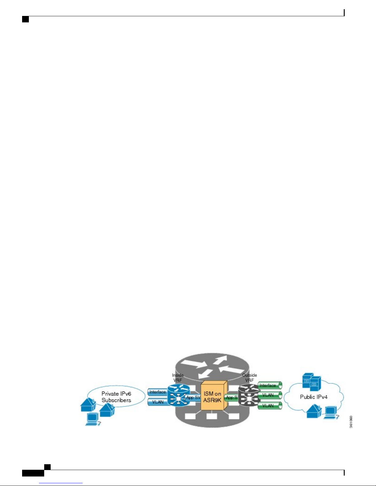
The following figure illustrates the implementation of NAT 44 over ISM
Cisco IOS XR Carrier Grade NAT Configuration Guide for the Cisco CRS Router, Release 5.2.x
8 OL-32659-01
Page 19
Implementing Carrier Grade NAT on Cisco IOS XR Software
The components of this illustration are as follows:
Private IP4 subscribers: It denotes a private network.
•
Interface/VLAN: It denotes a designated interface or VLAN which is associated with the VRF.
•
Inside VRF: It denotes the VRF that handles packets coming from the subscriber network. It is known
•
as inside VRF as it forwards packets from the private network.
App SVI: It denotes an application interface that forwards the data packet to and from the ISM. The data
•
packet may be sent from another line card through a backplane. Because the ISM card does not have a
physical interface, the APP SVI acts as a logical entry into it.
The inside VRF is bound to an App SVI. There are 2 App SVIs required; one for the inside VRF and
the other one for the outside VRF. Each App SVI pair will be associated with a unique "inside VRF"
and a unique public IP address pool. The VRF consists of a static route for forwarding packets to App
SVI1.
Outside VRF: It denotes the VRF that handles packets going out to the public network. It is known as
•
outside VRF as it forwards packets from the public network.
Public IPV4: It denotes a public network.
•
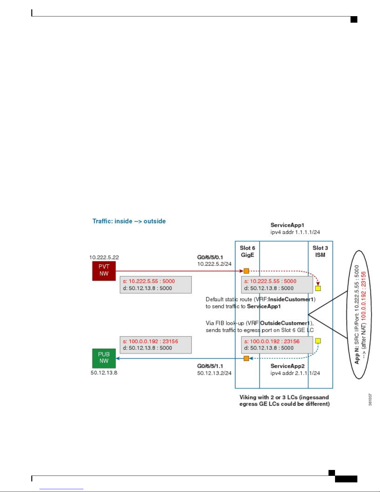
Implementing NAT 44 over ISM
The following figure illustrates the path of the data packet from a private network to a public network in a
NAT implementation.
The packet goes through the following steps when it travels from the private network to the public network:
OL-32659-01 9
Cisco IOS XR Carrier Grade NAT Configuration Guide for the Cisco CRS Router, Release 5.2.x
Page 20
Implementing NAT 44 over ISM
1
In the network shown in this figure, the packet travels from the host A (having the IP address 10.222.5.55)
in the private network to host B (having the IP address 5.5.5.2) in the public network. The private address
has to be mapped to the public address by NAT44 that is implemented in ISM.
2
The packet enters through the ingress port on the Gigabit Ethernet (GigE) interface at Slot 0. While using
NAT44, it is mandatory that the packet enters through VRF.
3
Once the packet reaches the designated interface or VLAN on ASR9K, it is forwarded to the inside VRF
either through static routing or ACL-based forwarding (ABL). After the inside VRF determines that the
packet needs address translation, it is forwarded to the App SVI that is bound to the VRF.
4
The packet is forwarded by AppSVI1 through a default static route (ivrf1). The destination address and
the port get translated because of the CGN configuration applied on ISM.
5
The ISM applies NAT44 to the packet and a translation entry is created. The CGN determines the destination
address from the FIB Look Up. It pushes the packet to the egress port.
6
The packet is then forwarded to the egress port on the interface through App SVI2. An inside VRF is
mapped to an outside VRF. The outside VRF is associated with this interface. The packet is forwarded by
App SVI2 through the default static route (ovrf1). Then the packet is sent to the public network.
7
The packets that do not need the address translation can bypass the App SVI and can be forwarded to the
destination through a different static route and a different egress port.
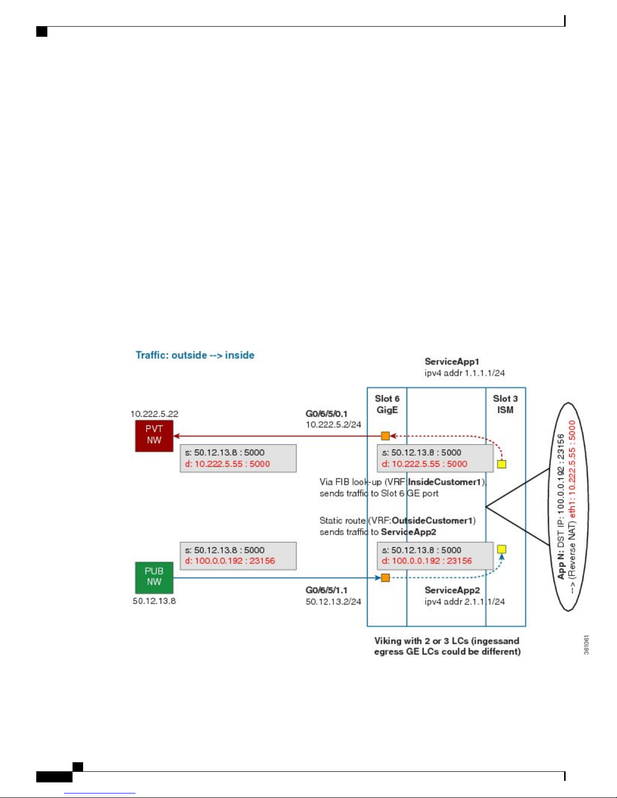
Implementing Carrier Grade NAT on Cisco IOS XR Software
The following figure illustrates the path of the packet coming from the public network to the private network.
The packet goes through the following steps when it travels from the public network to the private network:
Cisco IOS XR Carrier Grade NAT Configuration Guide for the Cisco CRS Router, Release 5.2.x
10 OL-32659-01
Page 21
Implementing Carrier Grade NAT on Cisco IOS XR Software
1
In the network shown in this figure, the packet travels from the host A (having the IP address 10.222.5.55)
in the public network to host B (having the IP address 5.5.5.2) in the private network. The public address
has to be mapped to the private address by NAT44 that is implemented in ISM.
2
The packet enters through the ingress port on the Gigabit Ethernet (GigE) interface at Slot 0.
3
Once the packet reaches the designated interface or VLAN on ASR9K, it is forwarded to the outside VRF
either through static routing or ACL-based forwarding (ABL).
4
The packet is forwarded by App SVI2 through a default static route. The destination address and the port
are mapped to the translated address.
5
The ISM applies NAT44 to the packet. The CGN determines the destination address from the FIB Look
Up. It pushes the packet to the egress port.
6
The packet is then forwarded to the egress port on the interface through App SVI2. Then the packet is sent
to the private network through the inside VRF.
7
The packets that do not need the address translation can bypass the App SVI and can be forwarded to the
destination through a different static route and a different egress port.
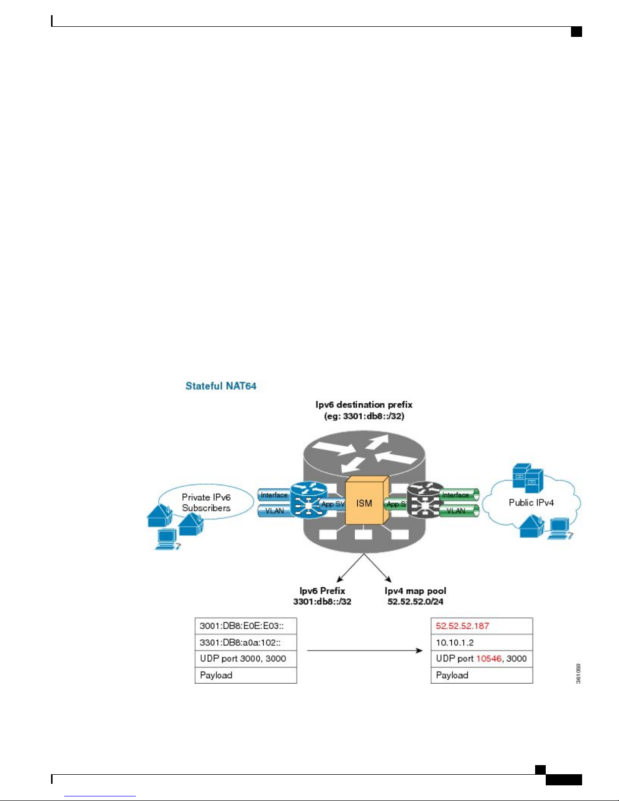
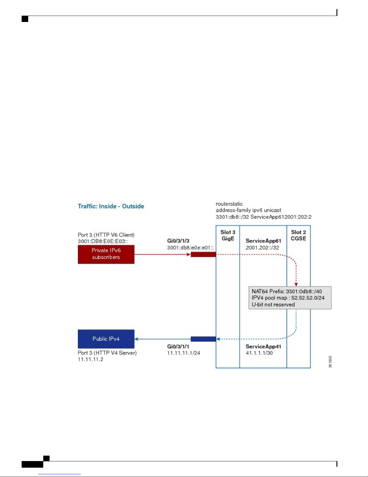
Implementing NAT 64 over ISM
Implementing NAT 64 over ISM
This section explains how NAT64 is implemented over ISM. The figure illustrates the implementation of
NAT64 over ISM.
The components of this implementation are as follows:
OL-32659-01 11
Cisco IOS XR Carrier Grade NAT Configuration Guide for the Cisco CRS Router, Release 5.2.x
Page 22
Implementing NAT 64 over ISM
• Private IP6 subscribers – It denotes a private network.
Interface/VLAN- It denotes a designated interface or VLAN which is associated with the VRF.
•
• Inside VRF – It denotes the VRF that handles packets coming from the subscriber network. It is known
as inside VRF as it forwards packets from the private network.
App SVI- It denotes an application interface that forwards the data packet to and from the ISM. The
•
data packet may be sent from another line card through a backplane. Because the ISM card does not
have a physical interface, the APP SVI acts as a logical entry into it.
The inside VRF is bound to an App SVI. There are 2 App SVIs required; one for the inside VRF and
the other one for the outside VRF. Each App SVI pair will be associated with a unique "inside VRF"
and a unique public IP address pool. The VRF consists of a static route for forwarding packets to App
SVI1.
Outside VRF- It denotes the VRF that handles packets going out to the public network. It is known as
•
outside VRF as it forwards packets from the public network.
Public IPV4- It denotes a public network.
•
The following figure illustrates the path of the data packet from a private network to a public network in a
NAT64 implementation.
Implementing Carrier Grade NAT on Cisco IOS XR Software
The packet goes through the following steps when it travels from the private network to the public network:
1
In the network shown in this figure, the packet travels from the host A (having the IP address
3001:DB8:E0E:E03::/40) in the private network to host B (having the IP address 11.11.11.2) in the public
network. The private address has to be mapped to the public address by NAT64 that is implemented in
ISM.
2
The packet enters through the ingress port on the Gigabit Ethernet (GigE) interface at Slot 3.
Cisco IOS XR Carrier Grade NAT Configuration Guide for the Cisco CRS Router, Release 5.2.x
12 OL-32659-01
Page 23
Implementing Carrier Grade NAT on Cisco IOS XR Software
3
Once the packet reaches the designated interface or VLAN on ASR9K, it is forwarded to the inside VRF
either through static routing or ACL-based forwarding (ABL). Based on this routing decision, the packet
that needs address translation is determined and is forwarded to the App SVI that is bound to the VRF.
4
The packet is forwarded by AppSVI1 through a default static route. The destination address and the port
get translated because of the CGN configuration applied on ISM.
5
The ISM applies NAT64 to the packet and a translation entry is created. The CGN determines the destination
address from the FIB Look Up. It pushes the packet to the egress port.
6
The packet is then forwarded to the egress port on the interface through App SVI2. The packet is forwarded
by App SVI2 through the default static route. Then the packet is sent to the public network.
7
The packets that do not need the address translation can bypass the App SVI and can be forwarded to the
destination through a different static route and a different egress port.
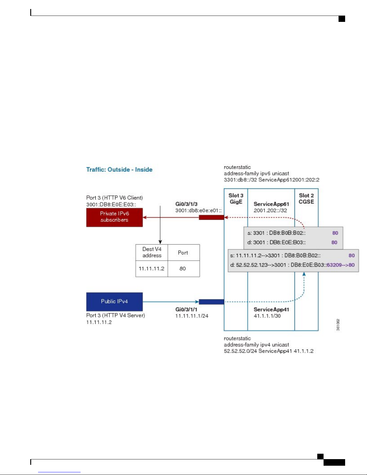
The following figure illustrates the path of the packet coming from the public network to the private network.
Implementing NAT 64 over ISM
The packet goes through the following steps when it travels from the public network to the private network:
1
In the network shown in this figure, the packet travels from the host A (having the IP address 11.11.11.2)
in the public network to host B (having the IP address 3001:DB8:E0E:E03::) in the private network. The
public address has to be mapped to the private address by NAT64 that is implemented in ISM.
2
The packet enters through the ingress port on the Gigabit Ethernet (GigE) interface at Slot 3.
OL-32659-01 13
Cisco IOS XR Carrier Grade NAT Configuration Guide for the Cisco CRS Router, Release 5.2.x
Page 24

Double NAT 444
3
4
5
6
7
Double NAT 444
The Double NAT 444 solution offers the fastest and simplest way to address the IPv4 depletion problem
without requiring an upgrade to IPv6 anywhere in the network. Service providers can continue offering new
IPv4 customers access to the public IPv4 Internet by using private IPv4 address blocks, if the service provider
is large enough; However, they need to have an overlapping RFC 1918 address space, which forces the service
provider to partition their network management systems and creates complexity with access control lists
(ACL).
Double NAT 444 uses the edge NAT and CGN to hold the translation state for each session. For example,
both NATs must hold 100 entries in their respective translation tables if all the hosts in the residence of a
subscriber have 100 connections to hosts on the Internet). There is no easy way for a private IPv4 host to
communicate with the CGN to learn its public IP address and port information or to configure a static incoming
port forwarding.
Implementing Carrier Grade NAT on Cisco IOS XR Software
Once the packet reaches the designated interface or VLAN on ASR9K, it is forwarded to the outside VRF
either through static routing or ACL-based forwarding (ABL). Based on this routing decision, the packet
is forwarded to the App SVI that is bound to the VRF.
The packet is forwarded by App SVI2 through a default static route. The destination address and the port
are mapped to the translated address.
The ISM applies NAT64 to the packet. The CGN determines the destination address from the FIB Look
Up. It pushes the packet to the egress port.
The packet is then forwarded to the egress port on the interface through App SVI2. Then the packet is sent
to the private network through the inside VRF.
The packets that do not need the address translation can bypass the App SVI and can be forwarded to the
destination through a different static route and a different egress port.
Address Family Translation
The IPv6-only to IPv4-only protocol is referred to as address family translation (AFT). The AFT translates
the IP address from one address family into another address family. For example, IPv6 to IPv4 translation is
called NAT 64 or IPv4 to IPv6 translation is called NAT 46.
Cisco Carrier NAT Applications
These applications are deployed on the CGSE line card.
IPv4/IPv6 Stateless Translator
IPv4/IPv6 Stateless Translator (XLAT), which runs on the CRS Carrier Grade Services Engine (CGSE),
enables an IPv4-only endpoint that is situated in an IPv4-only network, to communicate with an IPv6-only
end-point that is situated in an IPv6-only network. This like-to-unlike address family connectivity paradigm
provides backwards compatibility between IPv6 and IPv4.
Cisco IOS XR Carrier Grade NAT Configuration Guide for the Cisco CRS Router, Release 5.2.x
14 OL-32659-01
Page 25

Implementing Carrier Grade NAT on Cisco IOS XR Software
A Stateless XLAT (SL-XLAT) does not create or maintain any per-session or per-flow data structures. It is
an algorithmic operation performed on the IP packet headers that results in the translation of an IPv4 packet
to an IPv6 packet, and vice-versa. SL-XLAT requires Cisco IOS XR Software Release 3.9.3 or 4.0.1 or 4.1.0
or later.
IPv6 Rapid Deployment
IPv6 Rapid Deployment (6RD) is a mechanism that allows service providers to provide a unicast IPv6 service
to customers over their IPv4 network.
Stateful NAT64
The Stateful NAT64 (Network Address Translation 64) feature provides a translation mechanism that translates
IPv6 packets into IPv4 packets and vice versa. NAT64 allows IPv6-only clients to contact IPv4 servers using
unicast UDP, TCP, or ICMP. The public IPv4 address can be shared with several IPv6-only clients. NAT64
supports communication between:
IPv6 Rapid Deployment
NAT64 is implemented on the Cisco CRS router CGSE platform. CGSE (Carrier Grade Service Engine) has
four octeons and supports 20 Gbps full duplex traffic. It works on Linux operating system and traffic into
CGSE is forwarded using serviceApp interfaces. SVIs (Service Virtual Interfaces) are configured to enable
traffic to flow in and out of CGSE.
Each NAT64 instance configured is associated with two serviceApps for the following purposes:
NAT64 instance parameters are configured using the CGN CLI. The NAT64 application in the octeons updates
its NAT64 instance and serviceApp databases, which are used to perform the translation between IPv6 and
IPv4 and vice versa.
Active CGN instance configuration is replicated in the standby CGN instance through the XR control plane.
Translations that are established on the Active CGN instance are exported to the Standby CGN instance as
the failure of the Active CGN affects the service until translations are re-established through normal packet
flow. Service interruption is moderate for the given fault detection time and translation learning rate in terms
of seconds or tens of seconds for a large translation database.
Dual Stack Lite
IPv6 Network and Public IPv4 Internet
•
Public IPv6 Internet and IPv4 Network
•
One serviceApp is used to carry traffic from IPv6 side
•
Another serviceApp is used to carry traffic from IPv4 side of the NAT64.
•
The Dual Stack Lite (DS-Lite) feature enables legacy IPv4 hosts and server communication over both IPv4
and IPv6 networks. Also, IPv4 hosts may need to access IPv4 internet over an IPv6 access network. The IPv4
hosts will have private addresses which need to have network address translation (NAT) completed before
reaching the IPv4 internet. The Dual Stack Lite application has these components:
OL-32659-01 15
Cisco IOS XR Carrier Grade NAT Configuration Guide for the Cisco CRS Router, Release 5.2.x
Page 26

Port Control Protocol
Implementing Carrier Grade NAT on Cisco IOS XR Software
Basic Bridging BroadBand Element (B4): This is a Customer Premises Equipment (CPE) router that
•
is attached to the end hosts. The IPv4 packets entering B4 are encapsulated using a IPv6 tunnel and sent
to the Address Family Transition Router (AFTR).
Address Family Transition Router(AFTR): This is the router that terminates the tunnel from the B4.
•
It decapsulates the tunneled IPv4 packet, translates the network address and routes to the IPv4 network.
In the reverse direction, IPv4 packets coming from the internet are reverse network address translated
and the resultant IPv4 packets are sent the B4 using a IPv6 tunnel.
The Dual Stack Lite feature helps in these functions:
1
Tunnelling IPv4 packets from CE devices over IPv6 tunnels to the CGSE blade.
2
Decapsulating the IPv4 packet and sending the decapsulated content to the IPv4 internet after completing
network address translation.
3
In the reverse direction completing reverse-network address translation and then tunnelling them over
IPv6 tunnels to the CPE device.
IPv6 traffic from the CPE device is natively forwarded.
Port Control Protocol
Port Control Protocol (PCP) allows an IPv6 or IPv4 host to control how incoming IPv6 or IPv4 packets are
translated and forwarded by a network address translator.
PCP version 1 as documented in http://tools.ietf.org/html/draft-ietf-pcp-base-19 is supported.
It also allows packets to be received from the Internet to a host and allows a host to reduce keepalive traffic
of connections to a server.
Policy Functions
Application Level Gateway
The Application Level Gateway (ALG) deals with the applications that are embedded in the IP address payload.
Active File Transfer Protocol (FTP), Point-to-Point Tunneling Protocol (PPTP), and Real Time Streaming
Protocol (RTSP) are supported.
FTP-ALG
CGN supports both passive and active FTP. FTP clients are supported with inside (private) address and servers
with outside (public) addresses. Passive FTP is provided by the basic NAT function. Active FTP is used with
the ALG.
RTSP-ALG
CGN supports the Real Time Streaming Protocol (RTSP), an application-level protocol for control over the
delivery of data with real-time properties. RTSP provides an extensible framework to enable controlled,
Cisco IOS XR Carrier Grade NAT Configuration Guide for the Cisco CRS Router, Release 5.2.x
16 OL-32659-01
Page 27

Implementing Carrier Grade NAT on Cisco IOS XR Software
on-demand delivery of real-time data, such as audio and video. Sources of data can include both live data
feeds and stored clips.
PPTP-ALG
PPTP is a network protocol that enables secure transfer of data from a remote client to a private enterprise
server by creating a Virtual Private Network (VPN). It is used to provide IP security at the network layer.
PPTP uses a control channel over TCP and a GRE tunnel operating to encapsulate PPP packets.
PPTP-ALG is a CGN solution that allows traffic from all clients through a single PPTP tunnel.
A PPTP tunnel is instantiated on the TCP port. This TCP connection is then used to initiate and manage a
second GRE tunnel to the same peer.
PPTP uses an access controller and network server to establish a connection.
PPTP Access Controller (PAC)
A device attached to one or more PSTN or ISDN lines capable of PPP operation and handling the PPTP
protocol. It terminates the PPTP tunnel and provides VPN connectivity to a remote client.
PPTP Network Server (PNS)
A device which provides the interface between the Point-to-Point Protocol (encapsulated in the PPTP protocol)
and a LAN or WAN. The PNS uses the PPTP protocol to support tunneling between a PPTP PAC and the
PNS. It requests to establish a VPN connectivity using PPTP tunnel.
Control Connection
A control connection is established between a PAC and a PNS for TCP.
Tunnel
A tunnel carries GRE encapsulated PPP datagrams between a PAC and a PNS
TCP Maximum Segment Size Adjustment
Note
Active FTP, PPTP ALG, and RTSP ALG are supported on NAT44 applications. Active FTP and RTSP
ALG are supported on DS-Lite applications.
TCP Maximum Segment Size Adjustment
When a host initiates a TCP session with a server, the host negotiates the IP segment size by using the maximum
segment size (MSS) option. The value of the MSS option is determined by the maximum transmission unit
(MTU) that is configured on the host.
Static Port Forwarding
Static port forwarding helps in associating a private IP address and port with a statically allocated public IP
and port. After you have configured static port forwarding, this association remains intact and does not get
removed due to timeouts until the CGSE is rebooted. In case of redundant CGSE cards, it remains intact until
both of the CGSEs are reloaded together or the router is reloaded. There are remote chances that after a reboot,
this association might change. This feature helps in cases where server applications running on the private
network needs access from public internet.
OL-32659-01 17
Cisco IOS XR Carrier Grade NAT Configuration Guide for the Cisco CRS Router, Release 5.2.x
Page 28

1:1 Redundancy
1:1 Redundancy
CGSE and CGSE Plus support 1:1 redundancy. Two CGSE or CGSE Plus cards can be placed in the
active-standby configuration. The card that comes up first gets into the active mode first. If the first card that
is in the active mode fails, the second card that is in the standby mode becomes active and processes the traffic.
When the failure occurs, the switchover occurs within a second. This redundancy model is in the warm standby
mode as the second card is already booted and preconfigured. Once it becomes active, it only has to re-establish
the sessions.
Implementing Carrier Grade NAT on Cisco IOS XR Software
Note
The 1:1 redundancy feature does not support the mixing of CGSE and CGSE Plus cards. So ensure that
you use either two CGSE cards or two CGSE Plus cards.
You can check the status of the redundancy of the CGSE or CGSE Plus cards by using the show services
redundancy command.
The failover and failback operations can be forced by using the service redundancy command.
Back-to-Back Deployment
The CGSE and CGSE-PLUS cards can be used in Back-to-Back CRS chasis configuration. In this configuration,
the active card and the standby card are in different chasis, thereby supporting inter-chasis redundancy. The
performance of the cards on different chasis would be the same as it would be if they were co-allocated on
the same chasis.
Note
The two CGSE or CGSE-PLUS cards that are used in redundancy configuration can be in the same chassis
or different chassis.
Intelligent Port Management
Intelligent Port Management is an efficient and flexible way of managing the public ports. This management
process consists of the following features:
Configuration of multiple public address pools
•
Reduction of the minimum size of bulk allocation
•
Configuration of port limit per VRF
•
Configuration of same public pool across different NAT instances
•
Configuration of Multiple Public Address Pools
From this release onwards, you can create multiple pools of address for each inside VRF. This configuration
currently supports 8 address pools that do not overlap with each other.
Cisco IOS XR Carrier Grade NAT Configuration Guide for the Cisco CRS Router, Release 5.2.x
18 OL-32659-01
Page 29

Implementing Carrier Grade NAT on Cisco IOS XR Software
Throughput Measurement
Note
Ensure that you do not add more than 8 address pools as it might result in verification errors, thereby
leading to the rejection of the configuration.
Some of the considerations regarding the configuration of multiple public address pools are as follows:
The outside VRF and outside ServiceApp remain the same for different pools of addresses for a given
•
inside VRF.
Note
If the outside VRF and the outside ServiceApp are changed, then there are chances that
a subscriber packet is routed onto different outside VRFs and different ServiceApps at
various times. Hence if you try to configure different address pools with different outside
VRF and different ServiceApps, the configuration is rejected.
The maximum size of the public address pool is 65536 addresses per CGN instance.
•
The minimum size of the public address pool is 64 addresses.
•
When a particular address pool is deleted, the associated translations are also deleted.
•
Reduction of the Minimum Size of Bulk Allocation
The minimum size of bulk allocation has been reduced to 8. This size can be specified by using the
bulk-port-alloc size command.
Configuration of Port Limit per VRF
For NAT44, you can configure different port limits for different inside-VRF instances. The port limit specified
per VRF overrides the port limit value specified globally. But if the port limit per VRF is not specified, then
the global port limit is applied. This configuration is supported for CGSE as well as CGSE-PLUS.
If the port limit is reduced, CGSE or CGSE-PLUS card will not terminate any translation. But no new
translations are created until the usage by the subscribers for that VRF falls below the port limit.
Configuration of Same Public Address Pool across Different NAT instances
A public address pool can be reused by different instances of NAT. But the address pool can be reused only
by different CGN instances on different service cards. The syslog gives details on the CGN instances and the
address pool that is being reused.
Two or more different instances of CGN can act as active-standby in an N:1 redundancy. In such configurations,
two CGSE cards can be in active mode with different address pools. A third CGSE card can act a common
standby for both of them. In this case, it makes easy if the third CGSE card is allowed to reuse the address
pools used on the other 2 CGSE cards.
Throughput Measurement
The service card, like CGSE, has smaller throughput compared to the other cards in the platform. Therefore
it drops packets at the service application interface if the traffic diverted to it is more than it can handle. Hence
it becomes very important to measure the throughput for a service card. From this release onwards, the
OL-32659-01 19
Cisco IOS XR Carrier Grade NAT Configuration Guide for the Cisco CRS Router, Release 5.2.x
Page 30

Implementing Carrier Grade NAT on Cisco IOS XR Software
High Availability on the Data Path Service Virtual Interface (SVI)
throughput of the CGSE card for the last 1 second and the last 5 minutes can be seen by using the show cgn
utilization throughput command.
Considerations
Some of the considerations of the throughput measurement feature are as follows:
The traffic processed by CGSE is measured in terms of bits per second and packets per second for the
•
last 1 second as well as the last 5 minutes.
The throughput measurement is done of rthe traffic coming into CGSE, either from Inside-to-Outside
•
direction or from Outside-to-Inside direction.
High Availability on the Data Path Service Virtual Interface (SVI)
The CGSE already supports high availability tests to detect failures within specific CPU cores (the
service-plim-ha core-to-core test) so that an alert is generated if one or more CPU cores of a CGSE card should
fail. If configured, the CGSE card goes for a reload and traffic is diverted to standby (or other active cards
depending on the configuration) upon detecting any core failures. The CGSE already supports similar test to
confirm the integrity of the packet path by sending test packets via ServiceInfra interface (the service-plim-ha
data-path test). The card can configured to reload upon failure of this test as well.
However, till now, there were no test mechanism to confirm the integrity of path via ServiceApp interfaces
(which bring in and send out subscriber traffic). With this release, a test mechanism has been added for
ServiceApp interfaces configured for 6RD application (for both V4 and V6 ServiceApps). The test can be
enabled via configuration. The test packets are generated from CGSE and made to traverse through the fabric
and come back in to CGSE via ServiceApp interfaces. Should there be a failure in receiving the packets, a
syslog message is generated to alert the administrator. Optionally, the ServiceApp interfaces can be configured
to be shut down upon detecting failure of this test. Shutting down the failed ServiceApp interfaces is useful
in case of active-active configuration where traffic is automatically diverted to other CGSE blades and hence
traffic loss can be prevented without manual intervention.
After the high availability feature is configured, the CGSE can detect the conditions where the data path SVI
(ServiceApp interface) is not able to forward traffic. If such a condition is detected, then the following actions
are taken:
A syslog message is logged by default.
•
The SVI can be shut down. But you need to ensure that the packets are diverted to the SVIs of the other
•
available CGSEs.
Considerations
Some of the considerations regarding the high availability on the data path SVIs are as follows:
In the current release, the high availability configuration is supported only for V4 and V6 ServiceApps
•
of 6rd application.
In case of a failure, the syslog message is generated irrespective of the shutdown of the SVI instance.
•
Cisco IOS XR Carrier Grade NAT Configuration Guide for the Cisco CRS Router, Release 5.2.x
20 OL-32659-01
Page 31

Implementing Carrier Grade NAT on Cisco IOS XR Software
External Logging
External logging configures the export and logging of the NAT table entries, private bindings that are associated
with a particular global IP port address, and to use Netflow to export the NAT table entries.
Netflow v9 Support
The NAT44 and DS Lite features support Netflow for logging of the translation records. Logging of the
translation records can be mandated by for Lawful Intercept. The Netflow uses binary format and hence
requires software to parse and present the translation records.
Syslog Support
The NAT44, Stateful NAT64, and DS Lite features support Netflow for logging of the translation records.
Logging of the translation records can be mandated by for Lawful Intercept. The Netflow uses binary format
and hence requires software to parse and present the translation records.
In Cisco IOS XR Software Release 4.2.1 and later, the DS Lite and NAT44 features support Syslog as an
alternative to Netflow. Syslog uses ASCII format and hence can be read by users. However, the log data
volume is higher in Syslog than Netflow.
External Logging
Bulk Port Allocation
The creation and deletion of NAT sessions need to be logged and these create huge amount of data. These
are stored on Syslog collector which is supported over UDP. In order to reduce the volume of data generated
by the NAT device, bulk port allocation can be enabled. When bulk port allocation is enabled and when a
subscriber creates the first session, a number of contiguous outside ports are pre-allocated. A bulk allocation
message is logged indicating this allocation. Subsequent session creations will use one of the pre-allocated
port and hence does not require logging.
Session-logging and bulk port allocation are mutually exclusive.Note
Destination-Based Logging
Destination-Based Logging (DBL) includes destination IPv4 address and port number in the Netflow create
and delete records used by NAT44, Stateful NAT64, and DS-Lite applications. It is also known as
Session-Logging.
Session-Logging and Bulk Port Allocation are mutually exclusive.Note
OL-32659-01 21
Cisco IOS XR Carrier Grade NAT Configuration Guide for the Cisco CRS Router, Release 5.2.x
Page 32

Implementing Carrier Grade NAT on Cisco IOS XR Software
Implementing Carrier Grade NAT on Cisco IOS XR Software
Implementing Carrier Grade NAT on Cisco IOS XR Software
This chapter provides an overview of the implementation of Carrier Grade NAT on Cisco IOS XR Software.
Getting Started with the Carrier Grade NAT
Perform these tasks to get started with the CGN configuration tasks.
Configuring the Service Role
Perform this task to configure the service role on the specified location to start the CGN service.
Note
SUMMARY STEPS
DETAILED STEPS
Step 1
Example:
RP/0/RP0/CPU0:router# configure
Step 2
Example:
RP/0/RP0/CPU0:router(config)#
hw-module service cgn location
0/1/CPU0
Step 3
Removal of service role is strictly not recommended while the card is active. This puts the card into
FAILED state, which is service impacting.
configure
1.
hw-module service cgn location node-id
2.
end or commit
3.
PurposeCommand or Action
Enters global configuration mode.configure
Configures a CGN service role on location 0/1/CPU0.hw-module service cgn location node-id
Saves configuration changes.end or commit
Example:
RP/0/RP0/CPU0:router(config)# end
or
RP/0/RP0/CPU0:router(config)# commit
Cisco IOS XR Carrier Grade NAT Configuration Guide for the Cisco CRS Router, Release 5.2.x
22 OL-32659-01
When you issue the end command, the system prompts you to commit
•
changes:
Uncommitted changes found, commit them before exiting
(yes/no/cancel)?
[cancel]:
Page 33

Implementing Carrier Grade NAT on Cisco IOS XR Software
Getting Started with the Carrier Grade NAT
PurposeCommand or Action
Entering yes saves configuration changes to the running
◦
configuration file, exits the configuration session, and returns the
router to EXEC mode.
Entering no exits the configuration session and returns the router
◦
to EXEC mode without committing the configuration changes.
Entering cancel leaves the router in the current configuration
◦
session without exiting or committing the configuration changes.
Use the commit command to save the configuration changes to the
•
running configuration file and remain within the configuration session.
Configuring the Service Instance and Location for the Carrier Grade NAT
Perform this task to configure the service instance and location for the CGN application.
SUMMARY STEPS
configure
1.
service cgn instance-name
2.
service-location preferred-active node-id [preferred-standby node-id]
3.
end or commit
4.
DETAILED STEPS
PurposeCommand or Action
Step 1
Step 2
Step 3
Example:
RP/0/RP0/CPU0:router# configure
service cgn instance-name
Example:
RP/0/RP0/CPU0:router(config)# service cgn
cgn1
RP/0/RP0/CPU0:router(config-cgn)#
service-location preferred-active node-id
[preferred-standby node-id]
Enters global configuration mode.configure
Configures the instance named cgn1 for the CGN application and enters
CGN configuration mode.
Configures the active and standby locations for the CGN application.
OL-32659-01 23
Cisco IOS XR Carrier Grade NAT Configuration Guide for the Cisco CRS Router, Release 5.2.x
Page 34

Getting Started with the Carrier Grade NAT
Example:
RP/0/RP0/CPU0:router(config-cgn)#
service-location preferred-active
0/1/CPU0 preferred-standby 0/4/CPU0
Step 4
Example:
RP/0/RP0/CPU0:router(config-cgn)# end
or
RP/0/RP0/CPU0:router(config-cgn)# commit
Implementing Carrier Grade NAT on Cisco IOS XR Software
PurposeCommand or Action
Saves configuration changes.end or commit
When you issue the end command, the system prompts you to
•
commit changes:
Uncommitted changes found, commit them before exiting
(yes/no/cancel)?
[cancel]:
Entering yes saves configuration changes to the running
◦
configuration file, exits the configuration session, and returns
the router to EXEC mode.
Configuring the Service Virtual Interfaces
Configuring the Infrastructure Service Virtual Interface
Perform this task to configure the infrastructure service virtual interface (SVI) to forward the control traffic.
The subnet mask length must be at least 30 (denoted as /30). CGSE uses SVI and it is therefore recommended
that access control list (ACL) be configured to protect it from any form of denial of service attacks. For a
sample ACL configuration, see Configuring ACL for a Infrastructure Service Virtual Interface: Example,
page 80.
Entering no exits the configuration session and returns the
◦
router to EXEC mode without committing the configuration
changes.
Entering cancel leaves the router in the current configuration
◦
session without exiting or committing the configuration
changes.
Use the commit command to save the configuration changes to
•
the running configuration file and remain within the configuration
session.
Note
Do not remove or modify service infra interface configuration when the card is in Active state. The
configuration is service affecting and the line card must be reloaded for the changes to take effect.
Cisco IOS XR Carrier Grade NAT Configuration Guide for the Cisco CRS Router, Release 5.2.x
24 OL-32659-01
Page 35

Implementing Carrier Grade NAT on Cisco IOS XR Software
SUMMARY STEPS
configure
1.
interface ServiceInfra value
2.
service-location node-id
3.
ipv4 address address/mask
4.
end or commit
5.
reload
6.
DETAILED STEPS
Getting Started with the Carrier Grade NAT
PurposeCommand or Action
Step 1
Step 2
Step 3
Step 4
Step 5
Example:
RP/0/RP0/CPU0:router# configure
interface ServiceInfra value
Example:
RP/0/RP0/CPU0:router(config)# interface
ServiceInfra 1
RP/0/RP0/CPU0:router(config-if)#
service-location node-id
Example:
RP/0/RP0/CPU0:router(config-if)#
service-location 0/1/CPU0
ipv4 address address/mask
Example:
RP/0/RP0/CPU0:router(config-if)# ipv4
address 1.1.1.1/30
Example:
RP/0/RP0/CPU0:router(config-if)# end
or
RP/0/RP0/CPU0:router(config-if)# commit
Enters global configuration mode.configure
Configures the infrastructure service virtual interface (SVI) as 1 and
enters CGN configuration mode.
Configures the location of the CGN service for the infrastructure SVI.
Sets the primary IPv4 address for an interface.
Saves configuration changes.end or commit
When you issue the end command, the system prompts you to
•
commit changes:
Uncommitted changes found, commit them before exiting
(yes/no/cancel)?
OL-32659-01 25
[cancel]:
Entering yes saves configuration changes to the running
◦
configuration file, exits the configuration session, and returns
the router to EXEC mode.
Entering no exits the configuration session and returns the
◦
router to EXEC mode without committing the configuration
changes.
Cisco IOS XR Carrier Grade NAT Configuration Guide for the Cisco CRS Router, Release 5.2.x
Page 36

Getting Started with the Carrier Grade NAT
Implementing Carrier Grade NAT on Cisco IOS XR Software
PurposeCommand or Action
Entering cancel leaves the router in the current configuration
◦
session without exiting or committing the configuration
changes.
Use the commit command to save the configuration changes to
•
the running configuration file and remain within the configuration
session.
Step 6
reload
Example:
RP/0/RP0/CPU0:Router#hw-mod location
0/3/cpu0 reload
Configuring the Application Service Virtual Interface
Perform this task to configure the application service virtual interface (SVI) to forward data traffic.
SUMMARY STEPS
configure
1.
interface ServiceApp value
2.
service cgn instance-name service-type nat44
3.
vrf vrf-name
4.
end or commit
5.
DETAILED STEPS
Once the configuration is complete, the card must be reloaded for
changes to take effect.
WARNING: This will take the requested node out of service.
Do you wish to continue?[confirm(y/n)] y
Step 1
Example:
RP/0/RP0/CPU0:router# configure
Step 2
26 OL-32659-01
interface ServiceApp value
Example:
RP/0/RP0/CPU0:router(config)# interface
ServiceApp 1
RP/0/RP0/CPU0:router(config-if)#
Cisco IOS XR Carrier Grade NAT Configuration Guide for the Cisco CRS Router, Release 5.2.x
PurposeCommand or Action
Enters global configuration mode.configure
Configures the application SVI as 1 and enters interface configuration
mode.
Page 37

Implementing Carrier Grade NAT on Cisco IOS XR Software
Getting Started with the Carrier Grade NAT
PurposeCommand or Action
Step 3
Step 4
Step 5
service cgn instance-name service-type nat44
Example:
RP/0/RP0/CPU0:router(config-if)#
service cgn cgn1
vrf vrf-name
Example:
RP/0/RP0/CPU0:router(config-if)# vrf
insidevrf1
Example:
RP/0/RP0/CPU0:router(config-if)# end
or
RP/0/RP0/CPU0:router(config-if)# commit
Configures the instance named cgn1 for the CGN application and enters
CGN configuration mode.
Configures the VPN routing and forwarding (VRF) for the Service
Application interface
Saves configuration changes.end or commit
When you issue the end command, the system prompts you to
•
commit changes:
Uncommitted changes found, commit them before exiting
(yes/no/cancel)?
[cancel]:
Entering yes saves configuration changes to the running
◦
configuration file, exits the configuration session, and returns
the router to EXEC mode.
Entering no exits the configuration session and returns the
◦
router to EXEC mode without committing the configuration
changes.
Configuring the Service Type Keyword Definition
Perform this task to configure the service type key definition.
SUMMARY STEPS
configure
1.
service cgn instance-name
2.
service-type nat44 nat1
3.
end or commit
4.
Entering cancel leaves the router in the current configuration
◦
session without exiting or committing the configuration
changes.
Use the commit command to save the configuration changes to the
•
running configuration file and remain within the configuration
session.
OL-32659-01 27
Cisco IOS XR Carrier Grade NAT Configuration Guide for the Cisco CRS Router, Release 5.2.x
Page 38

Configuring an Inside and Outside Address Pool Map
DETAILED STEPS
Implementing Carrier Grade NAT on Cisco IOS XR Software
PurposeCommand or Action
Step 1
Step 2
Step 3
Step 4
Example:
RP/0/RP0/CPU0:router# configure
service cgn instance-name
Example:
RP/0/RP0/CPU0:router(config)# service
cgn cgn1
RP/0/RP0/CPU0:router(config-cgn)#
service-type nat44 nat1
Example:
RP/0/RP0/CPU0:router(config-cgn)#
service-type nat44 nat1
Example:
RP/0/RP0/CPU0:router(config-cgn)# end
or
RP/0/RP0/CPU0:router(config-cgn)#
commit
Enters global configuration mode.configure
Configures the instance named cgn1 for the CGN application and enters
CGN configuration mode.
Configures the service type keyword definition for CGN NAT44
application.
Saves configuration changes.end or commit
When you issue the end command, the system prompts you to commit
•
changes:
Uncommitted changes found, commit them before exiting
(yes/no/cancel)?
[cancel]:
Entering yes saves configuration changes to the running
◦
configuration file, exits the configuration session, and returns
the router to EXEC mode.
Configuring an Inside and Outside Address Pool Map
Perform this task to configure an inside and outside address pool map with the following scenarios:
The designated address pool is used for CNAT.
•
One inside VRF is mapped to only one outside VRF.
•
Cisco IOS XR Carrier Grade NAT Configuration Guide for the Cisco CRS Router, Release 5.2.x
28 OL-32659-01
Entering no exits the configuration session and returns the
◦
router to EXEC mode without committing the configuration
changes.
Entering cancel leaves the router in the current configuration
◦
session without exiting or committing the configuration changes.
Use the commit command to save the configuration changes to the
•
running configuration file and remain within the configuration session.
Page 39

Implementing Carrier Grade NAT on Cisco IOS XR Software
Multiple non-overlapping address pools can be used in a specified outside VRF mapped to different
•
inside VRF.
Max Outside public pool per CGSE/CGN instance is 64 K or 65536 addresses. That is, if a /16 address
•
pool is mapped, then we cannot map any other pool to that particular CGSE.
Multiple inside vrf cannot be mapped to same outside address pool.
•
While Mapping Outside Pool Minimum value for prefix is 16 and maximum value is 26.
•
SUMMARY STEPS
configure
1.
service cgn instance-name
2.
service-type nat44 nat1
3.
inside-vrf vrf-name
4.
map [outside-vrf outside-vrf-name] address-pool address/prefix
5.
end or commit
6.
Configuring an Inside and Outside Address Pool Map
DETAILED STEPS
Step 1
Example:
RP/0/RP0/CPU0:router# configure
Step 2
service cgn instance-name
Example:
RP/0/RP0/CPU0:router(config)# service cgn
cgn1
RP/0/RP0/CPU0:router(config-cgn)#
Step 3
service-type nat44 nat1
Example:
RP/0/RP0/CPU0:router(config-cgn)#
service-type nat44 nat1
Step 4
inside-vrf vrf-name
Example:
RP/0/RP0/CPU0:router(config-cgn-nat44)#
inside-vrf insidevrf1
RP/0/RP0/CPU0:router(config-cgn-invrf)#
Step 5
map [outside-vrf outside-vrf-name] address-pool
address/prefix
PurposeCommand or Action
Enters global configuration mode.configure
Configures the instance named cgn1 for the CGN application and
enters CGN configuration mode.
Configures the service type keyword definition for CGN NAT44
application.
Configures an inside VRF named insidevrf1 and enters CGN inside
VRF configuration mode.
Configures an inside VRF to an outside VRF and address pool
mapping.
Example:
RP/0/RP0/CPU0:router(config-cgn-invrf)# map
outside-vrf outside vrf1 address-pool
10.10.0.0/16
OL-32659-01 29
Cisco IOS XR Carrier Grade NAT Configuration Guide for the Cisco CRS Router, Release 5.2.x
Page 40

Configuring the Policy Functions for the Carrier Grade NAT
or
RP/0/RP0/CPU0:router(config-cgn-invrf)# map
address-pool 100.1.0.0/16
Step 6
Example:
RP/0/RP0/CPU0:router(config-cgn-invrf-afi)#
end
or
RP/0/RP0/CPU0:router(config-cgn-invrf-afi)#
commit
Implementing Carrier Grade NAT on Cisco IOS XR Software
PurposeCommand or Action
Saves configuration changes.end or commit
When you issue the end command, the system prompts you
•
to commit changes:
Uncommitted changes found, commit them before exiting
(yes/no/cancel)?
[cancel]:
Entering yes saves configuration changes to the running
◦
configuration file, exits the configuration session, and
returns the router to EXEC mode.
Entering no exits the configuration session and returns
◦
the router to EXEC mode without committing the
configuration changes.
Entering cancel leaves the router in the current
◦
configuration session without exiting or committing the
configuration changes.
Use the commit command to save the configuration changes
•
to the running configuration file and remain within the
configuration session.
Configuring the Policy Functions for the Carrier Grade NAT
Perform these tasks to configure the policy functions.
Configuring Port Limit per Subscriber
Perform this task to restrict the number of ports used by an IPv6 address.
SUMMARY STEPS
configure
1.
service cgn instance-name
2.
service-type nat64 stateful instance-name
3.
portlimit value
4.
end or commit
5.
Cisco IOS XR Carrier Grade NAT Configuration Guide for the Cisco CRS Router, Release 5.2.x
30 OL-32659-01
Page 41

Implementing Carrier Grade NAT on Cisco IOS XR Software
DETAILED STEPS
Configuring the Policy Functions for the Carrier Grade NAT
PurposeCommand or Action
Step 1
Step 2
Step 3
Step 4
Step 5
Example:
RP/0/RP0/CPU0:router# configure
service cgn instance-name
Example:
RP/0/RP0/CPU0:router(config)# service cgn cgn1
RP/0/RP0/CPU0:router(config-cgn)#
service-type nat64 stateful instance-name
Example:
RP/0/RP0/CPU0:router(config-cgn)# service-type nat64
stateful nat64-inst
RP/0/RP0/CPU0:router(config-cgn-nat64-stateful)#
portlimit value
Example:
RP/0/RP0/CPU0:router(config-cgn-nat64-stateful)#portlimit
66
RP/0/RP0/CPU0:router(config-cgn-nat64-stateful)
Example:
RP/0/RP0/CPU0:router(config-cgn-nat64-stateful)# end
or
RP/0/RP0/CPU0:router(config-cgn-nat64-stateful)# commit
Enters global configuration mode.configure
Configures the instance named cgn1 for the CGv6
application and enters CGv6 configuration mode.
Configures the service type keyword definition for
CGv6 Stateful NAT64 application.
Configures a value to restrict the number of ports used
by an IPv6 address.
Saves configuration changes.end or commit
When you issue the end command, the system
•
prompts you to commit changes:
Uncommitted changes found, commit them
before exiting (yes/no/cancel)?
OL-32659-01 31
[cancel]:
Entering yes saves configuration changes
◦
to the running configuration file, exits the
configuration session, and returns the
router to EXEC mode.
Entering no exits the configuration session
◦
and returns the router to EXEC mode
without committing the configuration
changes.
Entering cancel leaves the router in the
◦
current configuration session without
exiting or committing the configuration
changes.
Use the commit command to save the
•
configuration changes to the running
Cisco IOS XR Carrier Grade NAT Configuration Guide for the Cisco CRS Router, Release 5.2.x
Page 42

Configuring the Policy Functions for the Carrier Grade NAT
Configuring the Timeout Value for the Protocol
Configuring the Timeout Value for the ICMP Protocol
Perform this task to configure the timeout value for the ICMP type for the CGN instance.
SUMMARY STEPS
Implementing Carrier Grade NAT on Cisco IOS XR Software
PurposeCommand or Action
configuration file and remain within the
configuration session.
DETAILED STEPS
Step 1
Example:
RP/0/RP0/CPU0:router# configure
Step 2
Step 3
service cgn instance-name
Example:
RP/0/RP0/CPU0:router(config)# service
cgn cgn1
RP/0/RP0/CPU0:router(config-cgn)#
service-type nat44 nat1
Example:
RP/0/RP0/CPU0:router(config-cgn)#
service-type nat44 nat1
configure
1.
service cgn instance-name
2.
service-type nat44 nat1
3.
protocol icmp
4.
timeoutseconds
5.
end or commit
6.
PurposeCommand or Action
Enters global configuration mode.configure
Configures the instance named cgn1 for the CGN application and enters
CGN configuration mode.
Configures the service type keyword definition for CGN NAT44
application.
Cisco IOS XR Carrier Grade NAT Configuration Guide for the Cisco CRS Router, Release 5.2.x
32 OL-32659-01
Page 43

Implementing Carrier Grade NAT on Cisco IOS XR Software
Configuring the Policy Functions for the Carrier Grade NAT
PurposeCommand or Action
Step 4
Step 5
Step 6
protocol icmp
Example:
RP/0/RP0/CPU0:router(config-cgn-nat44)#
protocol icmp
RP/0/RP0/CPU0:router(config-cgn-proto)#
timeoutseconds
Example:
RP/0/RP0/CPU0:router(config-cgn-proto)#
timeout 908
Example:
RP/0/RP0/CPU0:router(config-cgn-proto)#
end
or
RP/0/RP0/CPU0:router(config-cgn-proto)#
commit
Configures the ICMP protocol session. The example shows how to
configure the ICMP protocol for the CGN instance named cgn1.
Configures the timeout value as 908 for the ICMP session for the CGN
instance named cgn1.
Saves configuration changes.end or commit
When you issue the end command, the system prompts you to
•
commit changes:
Uncommitted changes found, commit them before exiting
(yes/no/cancel)?
[cancel]:
Entering yes saves configuration changes to the running
◦
configuration file, exits the configuration session, and returns
the router to EXEC mode.
Entering no exits the configuration session and returns the
◦
router to EXEC mode without committing the configuration
changes.
Configuring the Timeout Value for the TCP Session
Perform this task to configure the timeout value for either the active or initial sessions for TCP.
Entering cancel leaves the router in the current configuration
◦
session without exiting or committing the configuration
changes.
Use the commit command to save the configuration changes to
•
the running configuration file and remain within the configuration
session.
OL-32659-01 33
Cisco IOS XR Carrier Grade NAT Configuration Guide for the Cisco CRS Router, Release 5.2.x
Page 44

Configuring the Policy Functions for the Carrier Grade NAT
SUMMARY STEPS
configure
1.
service cgn instance-name
2.
service-type nat44 nat1
3.
protocol tcp
4.
session {active | initial} timeout seconds
5.
end or commit
6.
DETAILED STEPS
Implementing Carrier Grade NAT on Cisco IOS XR Software
PurposeCommand or Action
Step 1
Step 2
Step 3
Step 4
Step 5
Step 6
Example:
RP/0/RP0/CPU0:router# configure
service cgn instance-name
Example:
RP/0/RP0/CPU0:router(config)# service cgn
cgn1
RP/0/RP0/CPU0:router(config-cgn)#
service-type nat44 nat1
Example:
RP/0/RP0/CPU0:router(config-cgn)#
service-type nat44 nat1
protocol tcp
Example:
RP/0/RP0/CPU0:router(config-cgn-nat44)#
protocol tcp
RP/0/RP0/CPU0:router(config-cgn-proto)#
session {active | initial} timeout seconds
Example:
RP/0/RP0/CPU0:router(config-cgn-proto)#
session initial timeout 90
Enters global configuration mode.configure
Configures the instance named cgn1 for the CGN application and enters
CGN configuration mode.
Configures the service type keyword definition for CGN NAT44
application.
Configures the TCP protocol session. The example shows how to
configure the TCP protocol for the CGN instance named cgn1.
Configures the timeout value as 90 for the TCP session. The example
shows how to configure the initial session timeout.
Saves configuration changes.end or commit
Example:
RP/0/RP0/CPU0:router(config-cgn-proto)#
end
or
RP/0/RP0/CPU0:router(config-cgn-proto)#
commit
Cisco IOS XR Carrier Grade NAT Configuration Guide for the Cisco CRS Router, Release 5.2.x
34 OL-32659-01
When you issue the end command, the system prompts you to
•
commit changes:
Uncommitted changes found, commit them before exiting
(yes/no/cancel)?
[cancel]:
Page 45

Implementing Carrier Grade NAT on Cisco IOS XR Software
Configuring the Policy Functions for the Carrier Grade NAT
PurposeCommand or Action
Entering yes saves configuration changes to the running
◦
configuration file, exits the configuration session, and
returns the router to EXEC mode.
Entering no exits the configuration session and returns the
◦
router to EXEC mode without committing the configuration
changes.
Entering cancel leaves the router in the current
◦
configuration session without exiting or committing the
configuration changes.
Use the commit command to save the configuration changes to
•
the running configuration file and remain within the configuration
session.
Configuring the Timeout Value for the UDP Session
Perform this task to configure the timeout value for either the active or initial sessions for UDP.
SUMMARY STEPS
configure
1.
service cgn instance-name
2.
service-type nat44 nat1
3.
protocol udp
4.
session {active | initial} timeout seconds
5.
end or commit
6.
DETAILED STEPS
Step 1
Example:
RP/0/RP0/CPU0:router# configure
Step 2
service cgn instance-name
Example:
RP/0/RP0/CPU0:router(config)# service cgn
cgn1
RP/0/RP0/CPU0:router(config-cgn)#
PurposeCommand or Action
Enters global configuration mode.configure
Configures the instance named cgn1 for the CGN application and enters
CGN configuration mode.
OL-32659-01 35
Cisco IOS XR Carrier Grade NAT Configuration Guide for the Cisco CRS Router, Release 5.2.x
Page 46

Configuring the Policy Functions for the Carrier Grade NAT
Implementing Carrier Grade NAT on Cisco IOS XR Software
PurposeCommand or Action
Step 3
Step 4
Step 5
Step 6
service-type nat44 nat1
Example:
RP/0/RP0/CPU0:router(config-cgn)#
service-type nat44 nat1
protocol udp
Example:
RP/0/RP0/CPU0:router(config-cgn-nat44)#
protocol udp
RP/0/RP0/CPU0:router(config-cgn-proto)#
session {active | initial} timeout seconds
Example:
RP/0/RP0/CPU0:router(config-cgn-proto)#
session initial timeout 90
Example:
RP/0/RP0/CPU0:router(config-cgn-proto)#
end
or
RP/0/RP0/CPU0:router(config-cgn-proto)#
commit
Configures the service type keyword definition for CGN NAT44
application.
Configures the UDP protocol session. The example shows how to
configure the UDP protocol for the CGN instance named cgn1.
Configures the timeout value as 90 for the UDP session. The example
shows how to configure the initial session timeout.
Saves configuration changes.end or commit
When you issue the end command, the system prompts you to
•
commit changes:
Uncommitted changes found, commit them before exiting
(yes/no/cancel)?
[cancel]:
Entering yes saves configuration changes to the running
◦
configuration file, exits the configuration session, and
returns the router to EXEC mode.
Configuring the FTP ALG for NAT44 Instance
Perform this task to configure the FTP ALG for the specified NAT44 instance.
Entering no exits the configuration session and returns the
◦
router to EXEC mode without committing the configuration
changes.
Entering cancel leaves the router in the current
◦
configuration session without exiting or committing the
configuration changes.
Use the commit command to save the configuration changes to
•
the running configuration file and remain within the configuration
session.
Cisco IOS XR Carrier Grade NAT Configuration Guide for the Cisco CRS Router, Release 5.2.x
36 OL-32659-01
Page 47

Implementing Carrier Grade NAT on Cisco IOS XR Software
SUMMARY STEPS
configure
1.
service cgn instance-name
2.
service-type nat44 nat1
3.
alg activeFTP
4.
end or commit
5.
DETAILED STEPS
Configuring the Policy Functions for the Carrier Grade NAT
PurposeCommand or Action
Step 1
Step 2
Step 3
Step 4
Step 5
Example:
RP/0/RP0/CPU0:router# configure
service cgn instance-name
Example:
RP/0/RP0/CPU0:router(config)# service
cgn cgn1
RP/0/RP0/CPU0:router(config-cgn)#
Example:
RP/0/RP0/CPU0:router(config-cgn)#
service-type nat44 nat1
Example:
RP/0/RP0/CPU0:router(config-cgn-nat44)#
alg activeFTP
Example:
RP/0/RP0/CPU0:router(config-cgn)# end
or
RP/0/RP0/CPU0:router(config-cgn)# commit
Enters global configuration mode.configure
Configures the instance named cgn1 for the CGN application and enters
CGN configuration mode.
Configures the service type keyword definition for NAT44 application.service-type nat44 nat1
Configures the FTP ALG on the NAT44 instance.alg activeFTP
Saves configuration changes.end or commit
When you issue the end command, the system prompts you to
•
commit changes:
Uncommitted changes found, commit them before exiting
(yes/no/cancel)?
OL-32659-01 37
[cancel]:
Entering yes saves configuration changes to the running
◦
configuration file, exits the configuration session, and returns
the router to EXEC mode.
Entering no exits the configuration session and returns the
◦
router to EXEC mode without committing the configuration
changes.
Cisco IOS XR Carrier Grade NAT Configuration Guide for the Cisco CRS Router, Release 5.2.x
Page 48

Configuring the Policy Functions for the Carrier Grade NAT
PurposeCommand or Action
Use the commit command to save the configuration changes to
•
the running configuration file and remain within the configuration
session.
Configuring the RTSP ALG for NAT44 Instance
Perform this task to configure the ALG for the rtsp for the specified NAT44 instance. RTSP packets are
usually destined to port 554. But this is not always true because RTSP port value is configurable.
Implementing Carrier Grade NAT on Cisco IOS XR Software
Entering cancel leaves the router in the current configuration
◦
session without exiting or committing the configuration
changes.
SUMMARY STEPS
DETAILED STEPS
Step 1
Example:
RP/0/RP0/CPU0:router# configure
Step 2
service cgn instance-name
Example:
RP/0/RP0/CPU0:router(config)# service
cgn cgn1
RP/0/RP0/CPU0:router(config-cgn)#
Step 3
configure
1.
service cgn instance-name
2.
service-type nat44 nat1
3.
alg rtsp [server-port] value
4.
end or commit
5.
PurposeCommand or Action
Enters global configuration mode.configure
Configures the instance named cgn1 for the CGN application and enters
CGN configuration mode.
Configures the service type keyword definition for NAT44application.service-type nat44 nat1
Example:
RP/0/RP0/CPU0:router(config-cgn)#
service-type nat44 nat1
Cisco IOS XR Carrier Grade NAT Configuration Guide for the Cisco CRS Router, Release 5.2.x
38 OL-32659-01
Page 49

Implementing Carrier Grade NAT on Cisco IOS XR Software
Configuring the Policy Functions for the Carrier Grade NAT
PurposeCommand or Action
Step 4
Step 5
alg rtsp [server-port] value
Example:
RP/0/RP0/CPU0:router(config-cgn-nat44)#
alg rtsp server-port 5000
Example:
RP/0/RP0/CPU0:router(config-cgn)# end
or
RP/0/RP0/CPU0:router(config-cgn)# commit
Configures the rtsp ALG on the NAT44 instance for server port 5000.
The range is from 1 to 65535. The default port is 554.
Caution
The option of specifying a server port) is currently not
supported. Even if you configure some port, RTSP works only
on the default port (554).
Saves configuration changes.end or commit
When you issue the end command, the system prompts you to
•
commit changes:
Uncommitted changes found, commit them before exiting
(yes/no/cancel)?
[cancel]:
Entering yes saves configuration changes to the running
◦
configuration file, exits the configuration session, and returns
the router to EXEC mode.
Entering no exits the configuration session and returns the
◦
router to EXEC mode without committing the configuration
changes.
Entering cancel leaves the router in the current configuration
◦
session without exiting or committing the configuration
changes.
Configuring the PPTP ALG for a NAT44 Instance
SUMMARY STEPS
configure
1.
service cgn instance-name
2.
service-type nat44 nat1
3.
alg pptpAlg
4.
end or commit
5.
Use the commit command to save the configuration changes to the
•
running configuration file and remain within the configuration
session.
OL-32659-01 39
Cisco IOS XR Carrier Grade NAT Configuration Guide for the Cisco CRS Router, Release 5.2.x
Page 50

Configuring the Policy Functions for the Carrier Grade NAT
DETAILED STEPS
Implementing Carrier Grade NAT on Cisco IOS XR Software
PurposeCommand or Action
Step 1
Step 2
Step 3
Step 4
Step 5
Example:
RP/0/RP0/CPU0:router# configure
service cgn instance-name
Example:
RP/0/RP0/CPU0:router(config)# service
cgn cgn1
RP/0/RP0/CPU0:router(config-cgn)#
service-type nat44 nat1
Example:
RP/0/RP0/CPU0:router(config-cgn)#
service-type nat44 nat1
Example:
RP/0/RP0/CPU0:router(config-cgn-nat44)#
alg pptpAlg
Example:
RP/0/RP0/CPU0:router(config-cgn)# end
or
RP/0/RP0/CPU0:router(config-cgn)# commit
Enters global configuration mode.configure
Configures the instance named cgn1 for the CGN application and enters
CGN configuration mode.
Configures the service type keyword definition for NAT44 or DS-Lite
application.
Configures the pptp ALG on the CGN instance.alg pptpAlg
Saves configuration changes.end or commit
When you issue the end command, the system prompts you to
•
commit changes:
Uncommitted changes found, commit them before exiting
(yes/no/cancel)?
Cisco IOS XR Carrier Grade NAT Configuration Guide for the Cisco CRS Router, Release 5.2.x
40 OL-32659-01
[cancel]:
Entering yes saves configuration changes to the running
◦
configuration file, exits the configuration session, and returns
the router to EXEC mode.
Entering no exits the configuration session and returns the
◦
router to EXEC mode without committing the configuration
changes.
Entering cancel leaves the router in the current configuration
◦
session without exiting or committing the configuration
changes.
Use the commit command to save the configuration changes to
•
the running configuration file and remain within the configuration
session.
Page 51

Implementing Carrier Grade NAT on Cisco IOS XR Software
Configuring the Policy Functions for the Carrier Grade NAT
Configuring the TCP Adjustment Value for the Maximum Segment Size
Perform this task to configure the adjustment value for the maximum segment size (MSS) for the VRF. You
can configure the TCP MSS adjustment value on each VRF.
SUMMARY STEPS
configure
1.
service cgn instance-name
2.
service-type nat44 nat1
3.
inside-vrf vrf-name
4.
protocol tcp
5.
mss size
6.
end or commit
7.
DETAILED STEPS
Step 1
Step 2
Step 3
Step 4
Step 5
Example:
RP/0/RP0/CPU0:router# configure
service cgn instance-name
Example:
RP/0/RP0/CPU0:router(config)# service cgn cgn1
RP/0/RP0/CPU0:router(config-cgn)#
service-type nat44 nat1
Example:
RP/0/RP0/CPU0:router(config-cgn)#
service-location preferred-active 0/1/CPU0
preferred-standby 0/4/CPU0
inside-vrf vrf-name
Example:
RP/0/RP0/CPU0:router(config-cgn-nat44)# inside-vrf
insidevrf1
RP/0/RP0/CPU0:router(config-cgn-invrf)#
protocol tcp
Example:
RP/0/RP0/CPU0:router(config-cgn-invrf)# protocol
tcp
RP/0/RP0/CPU0:router(config-cgn-invrf-proto)#
PurposeCommand or Action
Enters global configuration mode.configure
Configures the instance named cgn1 for the CGN application
and enters CGN configuration mode.
Configures the service type keyword definition for CGN
NAT44 application.
Configures the inside VRF for the CGN instance named cgn1
and enters CGN inside VRF configuration mode.
Configures the TCP protocol session and enters CGN inside
VRF AFI protocol configuration mode.
OL-32659-01 41
Cisco IOS XR Carrier Grade NAT Configuration Guide for the Cisco CRS Router, Release 5.2.x
Page 52

Configuring the Policy Functions for the Carrier Grade NAT
Implementing Carrier Grade NAT on Cisco IOS XR Software
PurposeCommand or Action
Step 6
Step 7
mss size
Example:
RP/0/RP0/CPU0:router(config-cgn-invrf-afi-proto)#
mss 1100
Example:
RP/0/RP0/CPU0:router(config-cgn-invrf-proto)# end
or
RP/0/RP0/CPU0:router(config-cgn-invrf-proto)#
commit
Configures the adjustment MSS value as 1100 for the inside
VRF.
Saves configuration changes.end or commit
When you issue the end command, the system prompts
•
you to commit changes:
Uncommitted changes found, commit them before
exiting (yes/no/cancel)?
[cancel]:
Entering yes saves configuration changes to the
◦
running configuration file, exits the configuration
session, and returns the router to EXEC mode.
Entering no exits the configuration session and
◦
returns the router to EXEC mode without
committing the configuration changes.
Entering cancel leaves the router in the current
◦
configuration session without exiting or
committing the configuration changes.
Use the commit command to save the configuration
•
changes to the running configuration file and remain
within the configuration session.
Configuring the Refresh Direction for the Network Address Translation
Perform this task to configure the NAT mapping refresh direction as outbound for TCP and UDP traffic.
SUMMARY STEPS
configure
1.
service cgn instance-name
2.
service-type nat44 nat1
3.
refresh-direction Outbound
4.
end or commit
5.
Cisco IOS XR Carrier Grade NAT Configuration Guide for the Cisco CRS Router, Release 5.2.x
42 OL-32659-01
Page 53

Implementing Carrier Grade NAT on Cisco IOS XR Software
DETAILED STEPS
Configuring the Policy Functions for the Carrier Grade NAT
PurposeCommand or Action
Step 1
Step 2
Step 3
Step 4
Step 5
Example:
RP/0/RP0/CPU0:router# configure
service cgn instance-name
Example:
RP/0/RP0/CPU0:router(config)# service cgn cgn1
RP/0/RP0/CPU0:router(config-cgn)#
service-type nat44 nat1
Example:
RP/0/RP0/CPU0:router(config-cgn)# service-type nat44 nat1
refresh-direction Outbound
Example:
RP/0/RP0/CPU0:router(config-cgn-nat44)# protocol tcp
RP/0/RP0/CPU0:router(config-cgn-proto)#refresh-direction
Outbound
Example:
RP/0/RP0/CPU0:router(config-cgn)# end
or
RP/0/RP0/CPU0:router(config-cgn)# commit
Enters global configuration mode.configure
Configures the instance named cgn1 for the CGN
application and enters CGN configuration mode.
Configures the service type keyword definition for
NAT44 application.
Configures the NAT mapping refresh direction as
outbound for the CGN instance named cgn1.
Saves configuration changes.end or commit
When you issue the end command, the system
•
prompts you to commit changes:
Uncommitted changes found, commit them before
exiting (yes/no/cancel)?
OL-32659-01 43
[cancel]:
Entering yes saves configuration changes
◦
to the running configuration file, exits the
configuration session, and returns the router
to EXEC mode.
Entering no exits the configuration session
◦
and returns the router to EXEC mode
without committing the configuration
changes.
Entering cancel leaves the router in the
◦
current configuration session without
exiting or committing the configuration
changes.
Use the commit command to save the
•
configuration changes to the running
configuration file and remain within the
configuration session.
Cisco IOS XR Carrier Grade NAT Configuration Guide for the Cisco CRS Router, Release 5.2.x
Page 54

Configuring the Policy Functions for the Carrier Grade NAT
Configuring the Carrier Grade NAT for Static Port Forwarding
Perform this task to configure CGN for static port forwarding for reserved or nonreserved port numbers.
SUMMARY STEPS
configure
1.
service cgn instance-name
2.
service-type nat44 nat1
3.
inside-vrf vrf-name
4.
protocol tcp
5.
static-forward inside
6.
address address port number
7.
end or commit
8.
Implementing Carrier Grade NAT on Cisco IOS XR Software
PurposeCommand or Action
DETAILED STEPS
Step 1
Example:
RP/0/RP0/CPU0:router# configure
Step 2
Step 3
Step 4
service cgn instance-name
Example:
RP/0/RP0/CPU0:router(config)# service cgn cgn1
RP/0/RP0/CPU0:router(config-cgn)#
service-type nat44 nat1
Example:
RP/0/RP0/CPU0:router(config-cgn)# service-type nat44
nat1
inside-vrf vrf-name
Example:
RP/0/RP0/CPU0:router(config-cgn-nat44)# inside-vrf
insidevrf1
RP/0/RP0/CPU0:router(config-cgn-invrf)#
PurposeCommand or Action
Enters global configuration mode.configure
Configures the instance named cgn1 for the CGN
application and enters CGN configuration mode.
Configures the service type keyword definition for NAT44
application.
Configures the inside VRF for the CGN instance named
cgn1 and enters CGN inside VRF configuration mode.
Cisco IOS XR Carrier Grade NAT Configuration Guide for the Cisco CRS Router, Release 5.2.x
44 OL-32659-01
Page 55

Implementing Carrier Grade NAT on Cisco IOS XR Software
Configuring the Policy Functions for the Carrier Grade NAT
PurposeCommand or Action
Step 5
Step 6
Step 7
Step 8
protocol tcp
Example:
RP/0/RP0/CPU0:router(config-cgn-invrf)# protocol
tcp
RP/0/RP0/CPU0:router(config-cgn-invrf-proto)#
static-forward inside
Example:
RP/0/RP0/CPU0:router(config-cgn-invrf-proto)#
static-forward inside
RP/0/RP0/CPU0:router(config-cgn-ivrf-sport-inside)#
address address port number
Example:
RP/0/RP0/CPU0:router(config-cgn-ivrf-sport-inside)#
address 1.2.3.4 port 90
Example:
RP/0/RP0/CPU0:router(config-cgn-ivrf-sport-inside)#
end
or
RP/0/RP0/CPU0:router(config-cgn-ivrf-sport-inside)#
commit
Configures the TCP protocol session and enters CGN inside
VRF AFI protocol configuration mode.
Configures the CGN static port forwarding entries on
reserved or nonreserved ports and enters CGN inside static
port inside configuration mode.
Configures the CGN static port forwarding entries for the
inside VRF.
Saves configuration changes.end or commit
When you issue the end command, the system
•
prompts you to commit changes:
Uncommitted changes found, commit them before
exiting (yes/no/cancel)?
[cancel]:
Entering yes saves configuration changes to the
◦
running configuration file, exits the
configuration session, and returns the router to
EXEC mode.
Entering no exits the configuration session and
◦
returns the router to EXEC mode without
committing the configuration changes.
Entering cancel leaves the router in the current
◦
configuration session without exiting or
committing the configuration changes.
Use the commit command to save the configuration
•
changes to the running configuration file and remain
within the configuration session.
OL-32659-01 45
Cisco IOS XR Carrier Grade NAT Configuration Guide for the Cisco CRS Router, Release 5.2.x
Page 56

Configuring the Policy Functions for the Carrier Grade NAT
Configuring the Dynamic Port Ranges for NAT44
Perform this task to configure dynamic port ranges for TCP, UDP, and ICMP ports. The default value range
of 0 to 1023 is preserved and not used for dynamic translations. Therefore, if the value of dynamic port range
start is not configured explicitly, the dynamic port range value starts at 1024.
SUMMARY STEPS
configure
1.
service cgn instance-name
2.
service-type nat44 nat1
3.
dynamic port range start value
4.
end or commit
5.
6.
DETAILED STEPS
Implementing Carrier Grade NAT on Cisco IOS XR Software
Step 1
Step 2
Step 3
Step 4
Step 5
Example:
RP/0/RP0/CPU0:router# configure
service cgn instance-name
Example:
RP/0/RP0/CPU0:router(config)# service cgn cgn1
RP/0/RP0/CPU0:router(config-cgn)#
service-type nat44 nat1
Example:
RP/0/RP0/CPU0:router(config-cgn)# service-type nat44
nat1
dynamic port range start value
Example:
RP/0/RP0/CPU0:router(config-cgn-nat44)# dynamic port
range start 666
Example:
RP/0/RP0/CPU0:router(config-cgn-ivrf-sport-inside)#
end
or
RP/0/RP0/CPU0:router(config-cgn-ivrf-sport-inside)#
commit
PurposeCommand or Action
Enters global configuration mode.configure
Configures the instance named cgn1 for the CGN
application and enters CGN configuration mode.
Configures the service type keyword definition for NAT44
application.
Configures the value of dynamic port range start for a CGN
NAT 44 instance. The value can range from 1 to 65535.
The default value is 1024.
Saves configuration changes.end or commit
When you issue the end command, the system
•
prompts you to commit changes:
Uncommitted changes found, commit them before
exiting (yes/no/cancel)?
[cancel]:
Cisco IOS XR Carrier Grade NAT Configuration Guide for the Cisco CRS Router, Release 5.2.x
46 OL-32659-01
Entering yes saves configuration changes to the
◦
running configuration file, exits the
Page 57

Implementing Carrier Grade NAT on Cisco IOS XR Software
Step 6
Example:
Configuring the Policy Functions for the Carrier Grade NAT
PurposeCommand or Action
configuration session, and returns the router to
EXEC mode.
Entering no exits the configuration session and
◦
returns the router to EXEC mode without
committing the configuration changes.
Entering cancel leaves the router in the current
◦
configuration session without exiting or
committing the configuration changes.
Use the commit command to save the configuration
•
changes to the running configuration file and remain
within the configuration session.
What to Do Next
•
Configuring 1:1 Redundancy
Perform the following steps to configure 1:1 redundancy on CGSE or CGSE Plus cards.
SUMMARY STEPS
configure
1.
service cgn instance-name
2.
service-location preferred-active node-id [preferred-standby node-id]
3.
end or commit
4.
DETAILED STEPS
Step 1
Example:
RP/0/RP0/CPU0:router# configure
PurposeCommand or Action
Enters global configuration mode.configure
OL-32659-01 47
Cisco IOS XR Carrier Grade NAT Configuration Guide for the Cisco CRS Router, Release 5.2.x
Page 58

Configuring the Policy Functions for the Carrier Grade NAT
Implementing Carrier Grade NAT on Cisco IOS XR Software
PurposeCommand or Action
Step 2
Step 3
Step 4
service cgn instance-name
Example:
RP/0/RP0/CPU0:router(config)# service
cgn cgn1
RP/0/RP0/CPU0:router(config-cgn)#
service-location preferred-active node-id
[preferred-standby node-id]
Example:
RP/0/RP0/CPU0:router(config-cgn)#
service-location preferred-active
0/1/CPU0 preferred-standby 0/4/CPU0
Example:
RP/0/RP0/CPU0:router(config-cgn)# end
or
RP/0/RP0/CPU0:router(config-cgn)# commit
Configures the instance named cgn1 for the CGN application and enters
CGN configuration mode.
Configures the active and standby locations for the CGN application.
Saves configuration changes.end or commit
When you issue the end command, the system prompts you to
•
commit changes:
Uncommitted changes found, commit them before exiting
(yes/no/cancel)?
[cancel]:
Entering yes saves configuration changes to the running
◦
configuration file, exits the configuration session, and returns
the router to EXEC mode.
Entering no exits the configuration session and returns the
◦
router to EXEC mode without committing the configuration
changes.
Configuring Multiple Public Address Pools
Perform the following steps to configure multiple public address pools for an inside VRF.
Entering cancel leaves the router in the current configuration
◦
session without exiting or committing the configuration
changes.
Use the commit command to save the configuration changes to
•
the running configuration file and remain within the configuration
session.
Cisco IOS XR Carrier Grade NAT Configuration Guide for the Cisco CRS Router, Release 5.2.x
48 OL-32659-01
Page 59

Implementing Carrier Grade NAT on Cisco IOS XR Software
SUMMARY STEPS
configure
1.
service cgn instance-name
2.
service-type nat44 nat1
3.
inside-vrf vrf-name
4.
map [outside-vrf outside-vrf-name] address-pool address/prefix
5.
end or commit
6.
DETAILED STEPS
Configuring the Policy Functions for the Carrier Grade NAT
PurposeCommand or Action
Step 1
Step 2
Step 3
Step 4
Step 5
Example:
RP/0/RP0/CPU0:router# configure
service cgn instance-name
Example:
RP/0/RP0/CPU0:router(config)# service cgn
cgn1
RP/0/RP0/CPU0:router(config-cgn)#
service-type nat44 nat1
Example:
RP/0/RP0/CPU0:router(config-cgn)#
service-type nat44 nat1
inside-vrf vrf-name
Example:
RP/0/RP0/CPU0:router(config-cgn-nat44)#
inside-vrf insidevrf1
RP/0/RP0/CPU0:router(config-cgn-invrf)#
map [outside-vrf outside-vrf-name] address-pool
address/prefix
Enters global configuration mode.configure
Configures the instance named cgn1 for the CGN application and
enters CGN configuration mode.
Configures the service type keyword definition for CGN NAT44
application.
Configures an inside VRF named insidevrf1 and enters CGN inside
VRF configuration mode.
Configures an inside VRF to an outside VRF and address pool
mapping.
Example:
RP/0/RP0/CPU0:router(config-cgn-invrf)# map
outside-vrf outside vrf1 address-pool
10.10.0.0/16
or
RP/0/RP0/CPU0:router(config-cgn-invrf)# map
address-pool 100.1.0.0/16
Step 6
Example:
RP/0/RP0/CPU0:router(config-cgn-invrf-afi)#
end
or
OL-32659-01 49
Saves configuration changes.end or commit
When you issue the end command, the system prompts you
•
to commit changes:
Uncommitted changes found, commit them before exiting
(yes/no/cancel)?
Cisco IOS XR Carrier Grade NAT Configuration Guide for the Cisco CRS Router, Release 5.2.x
Page 60

Configuring the Policy Functions for the Carrier Grade NAT
RP/0/RP0/CPU0:router(config-cgn-invrf-afi)#
commit
Implementing Carrier Grade NAT on Cisco IOS XR Software
PurposeCommand or Action
[cancel]:
Entering yes saves configuration changes to the running
◦
configuration file, exits the configuration session, and
returns the router to EXEC mode.
Entering no exits the configuration session and returns
◦
the router to EXEC mode without committing the
configuration changes.
Entering cancel leaves the router in the current
◦
configuration session without exiting or committing the
configuration changes.
Use the commit command to save the configuration changes
•
to the running configuration file and remain within the
configuration session.
Configuring Port Limit per VRF
Perform the following steps to configure the port limit per VRF:
SUMMARY STEPS
configure
1.
service cgn instance-name
2.
service-type nat44 nat1
3.
portlimit value
4.
inside-vrf vrf-name
5.
portlimit value
6.
end or commit
7.
DETAILED STEPS
Step 1
Example:
RP/0/RP0/CPU0:router# configure
PurposeCommand or Action
Enters global configuration mode.configure
Cisco IOS XR Carrier Grade NAT Configuration Guide for the Cisco CRS Router, Release 5.2.x
50 OL-32659-01
Page 61

Implementing Carrier Grade NAT on Cisco IOS XR Software
Configuring the Policy Functions for the Carrier Grade NAT
PurposeCommand or Action
Step 2
Step 3
Step 4
Step 5
Step 6
Step 7
service cgn instance-name
Example:
RP/0/RP0/CPU0:router(config)# service
cgn cgn1
RP/0/RP0/CPU0:router(config-cgn)#
service-type nat44 nat1
Example:
RP/0/RP0/CPU0:router(config-cgn)#
service-type nat44 nat1
portlimit value
Example:
RP/0/RP0/CPU0:router(config-cgn-nat44)#
portlimit 100
inside-vrf vrf-name
Example:
RP/0/RP0/CPU0:router(config-cgn-nat44)#
inside-vrf insidevrf1
RP/0/RP0/CPU0:router(config-cgn-invrf)#
portlimit value
Example:
RP/0/RP0/CPU0:router(config-cgn-invrf)#
portlimit 300
Configures the instance named cgn1 for the CGN application and enters
CGN configuration mode.
Configures the service type keyword definition for CGN NAT44
application.
Limits the number of entries per address for each subscriber of the
system
Configures an inside VRF named insidevrf1 and enters CGN inside
VRF configuration mode.
Sets the port limit per VRF. The port limit value per VRF (300)
overrides the port limit value specified globally (100) . The port limit
value per VRF (300) is applied to all the subscribers in the insidevrf1.
Saves configuration changes.end or commit
Example:
RP/0/RP0/CPU0:router(config-cgn)# end
or
RP/0/RP0/CPU0:router(config-cgn)# commit
OL-32659-01 51
When you issue the end command, the system prompts you to
•
commit changes:
Uncommitted changes found, commit them before exiting
(yes/no/cancel)?
[cancel]:
Entering yes saves configuration changes to the running
◦
configuration file, exits the configuration session, and
returns the router to EXEC mode.
Entering no exits the configuration session and returns the
◦
router to EXEC mode without committing the configuration
changes.
Entering cancel leaves the router in the current configuration
◦
session without exiting or committing the configuration
changes.
Cisco IOS XR Carrier Grade NAT Configuration Guide for the Cisco CRS Router, Release 5.2.x
Page 62

Configuring the Policy Functions for the Carrier Grade NAT
PurposeCommand or Action
Use the commit command to save the configuration changes to
•
the running configuration file and remain within the configuration
session.
Configuring Same Address Pool for Different NAT Instances
Perform the following steps to configure same address pool for different NAT instances. Note that in the
following sample configuration, there are 2 NAT instances, cgn1 and cgn2.
SUMMARY STEPS
configure
1.
service cgn cgn1
2.
service-type nat44nat1
3.
inside-vrf insidevrf1
4.
map address-pool address/prefix
5.
end or commit
6.
configure
7.
service cgn cgn2
8.
service-type nat44 nat2
9.
inside-vrf insidevrf2
10.
map address-pool address/prefix
11.
end or commit
12.
Implementing Carrier Grade NAT on Cisco IOS XR Software
DETAILED STEPS
Step 1
Example:
RP/0/RP0/CPU0:router# configure
Step 2
52 OL-32659-01
service cgn cgn1
Example:
RP/0/RP0/CPU0:router(config)# service cgn
cgn1
RP/0/RP0/CPU0:router(config-cgn)#
Cisco IOS XR Carrier Grade NAT Configuration Guide for the Cisco CRS Router, Release 5.2.x
PurposeCommand or Action
Enters global configuration mode.configure
Configures the instance named cgn1 for the CGN application and
enters CGN configuration mode.
Page 63

Implementing Carrier Grade NAT on Cisco IOS XR Software
Configuring the Policy Functions for the Carrier Grade NAT
PurposeCommand or Action
Step 3
Step 4
Step 5
Step 6
service-type nat44nat1
Example:
RP/0/RP0/CPU0:router(config-cgn)#
service-type nat44 nat1
inside-vrf insidevrf1
Example:
RP/0/RP0/CPU0:router(config-cgn-nat44)#
inside-vrf insidevrf1
RP/0/RP0/CPU0:router(config-cgn-invrf)#
map address-pool address/prefix
Example:
RP/0/RP0/CPU0:router(config-cgn-invrf)# map
address-pool 100.1.0.0/16
Example:
RP/0/RP0/CPU0:router(config-cgn-invrf-afi)#
end
or
RP/0/RP0/CPU0:router(config-cgn-invrf-afi)#
commit
Configures the service type keyword definition for CGN NAT44
application.
Configures an inside VRF named insidevrf1 and enters CGN inside
VRF configuration mode.
Configures an inside VRF to an outside VRF and address pool
mapping.
Saves configuration changes.end or commit
When you issue the end command, the system prompts you
•
to commit changes:
Uncommitted changes found, commit them before exiting
(yes/no/cancel)?
[cancel]:
Entering yes saves configuration changes to the running
◦
configuration file, exits the configuration session, and
returns the router to EXEC mode.
Step 7
Example:
RP/0/RP0/CPU0:router# configure
Entering no exits the configuration session and returns
◦
the router to EXEC mode without committing the
configuration changes.
Entering cancel leaves the router in the current
◦
configuration session without exiting or committing the
configuration changes.
Use the commit command to save the configuration changes
•
to the running configuration file and remain within the
configuration session.
Enters global configuration mode.configure
OL-32659-01 53
Cisco IOS XR Carrier Grade NAT Configuration Guide for the Cisco CRS Router, Release 5.2.x
Page 64

Configuring the Policy Functions for the Carrier Grade NAT
Implementing Carrier Grade NAT on Cisco IOS XR Software
PurposeCommand or Action
Step 8
Step 9
Step 10
Step 11
Step 12
service cgn cgn2
Example:
RP/0/RP0/CPU0:router(config)# service cgn
cgn2
RP/0/RP0/CPU0:router(config-cgn)#
Example:
RP/0/RP0/CPU0:router(config-cgn)#
service-type nat44 nat1
inside-vrf insidevrf2
Example:
RP/0/RP0/CPU0:router(config-cgn-nat44)#
inside-vrf insidevrf2
RP/0/RP0/CPU0:router(config-cgn-invrf)#
map address-pool address/prefix
Example:
RP/0/RP0/CPU0:router(config-cgn-invrf)# map
address-pool 100.1.0.0/16
Example:
RP/0/RP0/CPU0:router(config-cgn)# end
or
RP/0/RP0/CPU0:router(config-cgn)# commit
Configures another NAT instance cgn2 for the CGN application
and enters CGN configuration mode. The NAT instance, cgn2, can
access the same address pool created in the first NAT instance, cgn1.
Hence you do not have to specify a different address pool here.
Configures the service type for CGN NAT44 application.service-type nat44 nat2
Configures an inside VRF named insidevrf2 and enters CGN inside
VRF configuration mode.
Configures an inside VRF to an outside VRF and address pool
mapping.
Saves configuration changes.end or commit
When you issue the end command, the system prompts you
•
to commit changes:
Uncommitted changes found, commit them before exiting
(yes/no/cancel)?
[cancel]:
Entering yes saves configuration changes to the running
◦
configuration file, exits the configuration session, and
returns the router to EXEC mode.
Entering no exits the configuration session and returns
◦
the router to EXEC mode without committing the
configuration changes.
Entering cancel leaves the router in the current
◦
configuration session without exiting or committing the
configuration changes.
Use the commit command to save the configuration changes
•
to the running configuration file and remain within the
configuration session.
Cisco IOS XR Carrier Grade NAT Configuration Guide for the Cisco CRS Router, Release 5.2.x
54 OL-32659-01
Page 65

Implementing Carrier Grade NAT on Cisco IOS XR Software
Configuring the Policy Functions for the Carrier Grade NAT
Configuring High Availability of Data Path Service Virtual Interface (SVI)
SUMMARY STEPS
configure
1.
service cgn instance-name
2.
service-type tunnel v6rd instance-name
3.
end or commit
4.
address-family ipv4
5.
interface ServiceApp41
6.
address-family ipv6
7.
interface ServiceApp61
8.
exit
9.
datapath-test
10.
end or commit
11.
DETAILED STEPS
Step 1
Example:
RP/0/RP0/CPU0:router# configure
Step 2
Step 3
service cgn instance-name
Example:
RP/0/RP0/CPU0:router(config-if)# service cgn cgn1
service-type tunnel v6rd instance-name
Example:
RP/0/RP0/CPU0:router(config-cgn)# service-type
tunnel v6rd 6rd1
RP/0/RP0/CPU0:router(config-cgn-tunnel-6rd)
Step 4
Example:
RP/0/RP0/CPU0:router(config-cgn-tunnel-v6rd)#
end
or
RP/0/RP0/CPU0:router(config-cgn-tunnel-v6rd)#
commit
PurposeCommand or Action
Enters global configuration mode.configure
Configures the instance named cgn1 for the CGv6 application,
and enters CGv6 configuration mode.
Configures the service-type as tunnel v6rd, and the instance
name as 6rd1.
Saves configuration changes.end or commit
When you issue the end command, the system prompts
•
you to commit changes:
Uncommitted changes found, commit them before
exiting (yes/no/cancel)?
[cancel]:
OL-32659-01 55
Entering yes saves configuration changes to the
◦
running configuration file, exits the configuration
session, and returns the router to EXEC mode.
Cisco IOS XR Carrier Grade NAT Configuration Guide for the Cisco CRS Router, Release 5.2.x
Page 66

Configuring the Policy Functions for the Carrier Grade NAT
Implementing Carrier Grade NAT on Cisco IOS XR Software
PurposeCommand or Action
Entering no exits the configuration session and
◦
returns the router to EXEC mode without
committing the configuration changes.
Entering cancel leaves the router in the current
◦
configuration session without exiting or committing
the configuration changes.
Use the commit command to save the configuration
•
changes to the running configuration file and remain
within the configuration session.
Step 5
Step 6
Step 7
Step 8
Step 9
Step 10
Step 11
Example:
RP/0/RP0/CPU0:router(config-cgn-tunnel-6rd)#
address-family ipv4
interface ServiceApp41
Example:
RP/0/RP0/CPU0:router(config-cgn-tunnel-6rd-afi)#
interface ServiceApp41
Example:
RP/0/RP0/CPU0:router(config-cgn-6rd-afi)#
address-family ipv6
interface ServiceApp61
Example:
RP/0/RP0/CPU0:router(config-cgn-6rd-afi)#
interface ServiceApp61
Example:
RP/0/RP0/CPU0:router(config-cgn-6rd-afi)# exit
RP/0/RP0/CPU0:router(config-cgn-6rd)#
datapath-test
Example:
RP/0/RP0/CPU0:router(config-cgn-6rd)#
datapath-test
Enters the address family IPv4 configuration mode.address-family ipv4
Specifies the ServiceApp on which IPv4 traffic enters and
leaves.
Enters the address family IPv6 configuration mode.address-family ipv6
Specifies the ServiceApp on which IPv6 traffic enters and
leaves.
Exits the address family configuration mode.exit
Specifies the ServiceApp on which IPv6 traffic enters and
leaves.
Saves configuration changes.end or commit
Example:
RP/0/RP0/CPU0:router(config-cgn-tunnel-v6rd)#
end
Cisco IOS XR Carrier Grade NAT Configuration Guide for the Cisco CRS Router, Release 5.2.x
56 OL-32659-01
Page 67

Implementing Carrier Grade NAT on Cisco IOS XR Software
or
RP/0/RP0/CPU0:router(config-cgn-tunnel-v6rd)#
commit
Configuring the Policy Functions for the Carrier Grade NAT
PurposeCommand or Action
When you issue the end command, the system prompts
•
you to commit changes:
Uncommitted changes found, commit them before
exiting (yes/no/cancel)?
[cancel]:
Entering yes saves configuration changes to the
◦
running configuration file, exits the configuration
session, and returns the router to EXEC mode.
Entering no exits the configuration session and
◦
returns the router to EXEC mode without
committing the configuration changes.
Entering cancel leaves the router in the current
◦
configuration session without exiting or committing
the configuration changes.
Use the commit command to save the configuration
•
changes to the running configuration file and remain
within the configuration session.
Configuring the Export and Logging for the Network Address Translation Table Entries
Configuring the Server Address and Port for Netflow Logging
Perform this task to configure the server address and port to log network address translation (NAT) table
entries for Netflow logging.
SUMMARY STEPS
configure
1.
service cgn instance-name
2.
service-type nat44 nat1
3.
inside-vrf vrf-name
4.
external-logging netflowv9
5.
server
6.
address address port number
7.
end or commit
8.
OL-32659-01 57
Cisco IOS XR Carrier Grade NAT Configuration Guide for the Cisco CRS Router, Release 5.2.x
Page 68

Configuring the Policy Functions for the Carrier Grade NAT
DETAILED STEPS
Implementing Carrier Grade NAT on Cisco IOS XR Software
PurposeCommand or Action
Step 1
Step 2
Step 3
Step 4
Step 5
Step 6
Example:
RP/0/RP0/CPU0:router# configure
service cgn instance-name
Example:
RP/0/RP0/CPU0:router(config)# service cgn cgn1
RP/0/RP0/CPU0:router(config-cgn)#
service-type nat44 nat1
Example:
RP/0/RP0/CPU0:router(config-cgn)# service-type nat44 nat1
inside-vrf vrf-name
Example:
RP/0/RP0/CPU0:router(config-cgn)# inside-vrf insidevrf1
RP/0/RP0/CPU0:router(config-cgn-invrf)#
external-logging netflowv9
Example:
RP/0/RP0/CPU0:router(config-cgn-invrf)# external-logging
netflowv9
RP/0/RP0/CPU0:router(config-cgn-invrf-af-extlog)#
server
Example:
RP/0/RP0/CPU0:router(config-cgn-invrf-af-extlog)# server
RP/0/RP0/CPU0:router(config-cgn-invrf-af-extlog-server)#
Enters global configuration mode.configure
Configures the instance named cgn1 for the CGN
application and enters CGN configuration mode.
Configures the service type keyword definition for
NAT44 application.
Configures the inside VRF for the CGN instance
named cgn1 and enters CGN inside VRF configuration
mode.
Configures the external-logging facility for the CGN
instance named cgn1 and enters CGN inside VRF
address family external logging configuration mode.
Configures the logging server information for the IPv4
address and port for the server that is used for the
netflowv9-based external-logging facility and enters
CGN inside VRF address family external logging
server configuration mode.
Step 7
address address port number
Example:
RP/0/RP0/CPU0:router(config-cgn-invrf-af-extlog-server)#
address 2.3.4.5 port 45
Step 8
Example:
RP/0/RP0/CPU0:router(config-cgn-invrf-af-extlog-server)#
end
or
RP/0/RP0/CPU0:router(config-cgn-invrf-af-extlog-server)#
commit
Cisco IOS XR Carrier Grade NAT Configuration Guide for the Cisco CRS Router, Release 5.2.x
58 OL-32659-01
Configures the IPv4 address and port number 45 to
log Netflow entries for the NAT table.
Saves configuration changes.end or commit
When you issue the end command, the system
•
prompts you to commit changes:
Uncommitted changes found, commit them before
exiting (yes/no/cancel)?
[cancel]:
Entering yes saves configuration changes
◦
to the running configuration file, exits the
Page 69

Implementing Carrier Grade NAT on Cisco IOS XR Software
Configuring the Policy Functions for the Carrier Grade NAT
PurposeCommand or Action
configuration session, and returns the router
to EXEC mode.
Entering no exits the configuration session
◦
and returns the router to EXEC mode
without committing the configuration
changes.
Entering cancel leaves the router in the
◦
current configuration session without
exiting or committing the configuration
changes.
Use the commit command to save the
•
configuration changes to the running
configuration file and remain within the
configuration session.
Configuring the Path Maximum Transmission Unit for Netflow Logging
Perform this task to configure the path maximum transmission unit (MTU) for the netflowv9-based
external-logging facility for the inside VRF.
SUMMARY STEPS
configure
1.
service cgn instance-name
2.
service-type nat44 nat1
3.
inside-vrf vrf-name
4.
external-logging netflowv9
5.
server
6.
path-mtu value
7.
end or commit
8.
DETAILED STEPS
Step 1
PurposeCommand or Action
Enters global configuration mode.configure
Example:
RP/0/RP0/CPU0:router# configure
OL-32659-01 59
Cisco IOS XR Carrier Grade NAT Configuration Guide for the Cisco CRS Router, Release 5.2.x
Page 70

Configuring the Policy Functions for the Carrier Grade NAT
Implementing Carrier Grade NAT on Cisco IOS XR Software
PurposeCommand or Action
Step 2
Step 3
Step 4
Step 5
Step 6
service cgn instance-name
Example:
RP/0/RP0/CPU0:router(config)# service cgn cgn1
RP/0/RP0/CPU0:router(config-cgn)#
service-type nat44 nat1
Example:
RP/0/RP0/CPU0:router(config-cgn)# service-type nat44 nat1
inside-vrf vrf-name
Example:
RP/0/RP0/CPU0:router(config-cgn)# inside-vrf insidevrf1
RP/0/RP0/CPU0:router(config-cgn-invrf)#
external-logging netflowv9
Example:
RP/0/RP0/CPU0:router(config-cgn-invrf)# external-logging
netflowv9
RP/0/RP0/CPU0:router(config-cgn-invrf-af-extlog)#
server
Example:
RP/0/RP0/CPU0:router(config-cgn-invrf-af-extlog)# server
RP/0/RP0/CPU0:router(config-cgn-invrf-af-extlog-server)#
Configures the instance named cgn1 for the CGN
application and enters CGN configuration mode.
Configures the service type keyword definition for
NAT44 application.
Configures the inside VRF for the CGN instance
named cgn1 and enters CGN inside VRF configuration
mode.
Configures the external-logging facility for the CGN
instance named cgn1 and enters CGN inside VRF
address family external logging configuration mode.
Configures the logging server information for the IPv4
address and port for the server that is used for the
netflowv9-based external-logging facility and enters
CGN inside VRF address family external logging
server configuration mode.
Step 7
Step 8
path-mtu value
Example:
RP/0/RP0/CPU0:router(config-cgn-invrf-af-extlog-server)#
path-mtu 2900
Example:
RP/0/RP0/CPU0:router(config-cgn-invrf-af-extlog-server)#
end
or
RP/0/RP0/CPU0:router(config-cgn-invrf-af-extlog-server)#
commit
Configures the path MTU with the value of 2900 for
the netflowv9-based external-logging facility.
Saves configuration changes.end or commit
When you issue the end command, the system
•
prompts you to commit changes:
Uncommitted changes found, commit them before
exiting (yes/no/cancel)?
[cancel]:
Entering yes saves configuration changes
◦
to the running configuration file, exits the
configuration session, and returns the router
to EXEC mode.
Entering no exits the configuration session
◦
and returns the router to EXEC mode
without committing the configuration
changes.
Cisco IOS XR Carrier Grade NAT Configuration Guide for the Cisco CRS Router, Release 5.2.x
60 OL-32659-01
Page 71

Implementing Carrier Grade NAT on Cisco IOS XR Software
Configuring the Refresh Rate for Netflow Logging
Configuring the Policy Functions for the Carrier Grade NAT
PurposeCommand or Action
Entering cancel leaves the router in the
◦
current configuration session without
exiting or committing the configuration
changes.
Use the commit command to save the
•
configuration changes to the running
configuration file and remain within the
configuration session.
SUMMARY STEPS
DETAILED STEPS
Step 1
Example:
RP/0/RP0/CPU0:router# configure
Step 2
service cgn instance-name
Example:
RP/0/RP0/CPU0:router(config)# service cgn cgn1
RP/0/RP0/CPU0:router(config-cgn)#
Perform this task to configure the refresh rate at which the Netflow-v9 logging templates are refreshed or
resent to the Netflow-v9 logging server.
configure
1.
service cgn instance-name
2.
service-type nat44 nat1
3.
inside-vrf vrf-name
4.
external-logging netflowv9
5.
server
6.
refresh-rate value
7.
end or commit
8.
PurposeCommand or Action
Enters global configuration mode.configure
Configures the instance named cgn1 for the CGN
application and enters CGN configuration mode.
OL-32659-01 61
Cisco IOS XR Carrier Grade NAT Configuration Guide for the Cisco CRS Router, Release 5.2.x
Page 72

Configuring the Policy Functions for the Carrier Grade NAT
Implementing Carrier Grade NAT on Cisco IOS XR Software
PurposeCommand or Action
Step 3
Step 4
Step 5
Step 6
Step 7
Step 8
service-type nat44 nat1
Example:
RP/0/RP0/CPU0:router(config-cgn)# service-type nat44 nat1
inside-vrf vrf-name
Example:
RP/0/RP0/CPU0:router(config-cgn)# inside-vrf insidevrf1
RP/0/RP0/CPU0:router(config-cgn-invrf)#
external-logging netflowv9
Example:
RP/0/RP0/CPU0:router(config-cgn-invrf)# external-logging
netflowv9
RP/0/RP0/CPU0:router(config-cgn-invrf-af-extlog)#
server
Example:
RP/0/RP0/CPU0:router(config-cgn-invrf-af-extlog)# server
RP/0/RP0/CPU0:router(config-cgn-invrf-af-extlog-server)#
refresh-rate value
Example:
RP/0/RP0/CPU0:router(config-cgn-invrf-af-extlog-server)#
refresh-rate 50
Configures the service type keyword definition for
NAT44 application.
Configures the inside VRF for the CGN instance
named cgn1 and enters CGN inside VRF configuration
mode.
Configures the external-logging facility for the CGN
instance named cgn1 and enters CGN inside VRF
address family external logging configuration mode.
Configures the logging server information for the IPv4
address and port for the server that is used for the
netflowv9-based external-logging facility and enters
CGN inside VRF address family external logging
server configuration mode.
Configures the refresh rate value of 50 to log
Netflow-based external logging information for an
inside VRF.
Saves configuration changes.end or commit
Example:
RP/0/RP0/CPU0:router(config-cgn-invrf-af-extlog-server)#
end
or
RP/0/RP0/CPU0:router(config-cgn-invrf-af-extlog-server)#
commit
When you issue the end command, the system
•
prompts you to commit changes:
Uncommitted changes found, commit them before
exiting (yes/no/cancel)?
[cancel]:
Entering yes saves configuration changes
◦
to the running configuration file, exits the
configuration session, and returns the router
to EXEC mode.
Entering no exits the configuration session
◦
and returns the router to EXEC mode
without committing the configuration
changes.
Entering cancel leaves the router in the
◦
current configuration session without
exiting or committing the configuration
changes.
Cisco IOS XR Carrier Grade NAT Configuration Guide for the Cisco CRS Router, Release 5.2.x
62 OL-32659-01
Page 73

Implementing Carrier Grade NAT on Cisco IOS XR Software
Configuring Session-Logging for a NAT44 or DS-Lite Instance
Perform this task to enable session-logging if destination IP and Port information needs to logged in the
Netflow records for each NAT44 or DS-Lite instance.
SUMMARY STEPS
configure
1.
service cgn instance-name
2.
service-type nat44 nat1 or service-type ds-lite ds-lite1
3.
inside-vrf vrf-name
4.
external-logging netflowv9 or external-loging netflow9
5.
server
6.
session-logging
7.
end or commit
8.
Configuring the Policy Functions for the Carrier Grade NAT
PurposeCommand or Action
Use the commit command to save the
•
configuration changes to the running
configuration file and remain within the
configuration session.
DETAILED STEPS
Step 1
Example:
RP/0/RP0/CPU0:router# configure
Step 2
Step 3
service cgn instance-name
Example:
RP/0/RP0/CPU0:router(config)# service cgn cgn1
RP/0/RP0/CPU0:router(config-cgn)#
service-type nat44 nat1 or service-type ds-lite ds-lite1
Example:
RP/0/RP0/CPU0:router(config-cgn)# service-type nat44 nat1
or
RP/0/RP0/CPU0:router(config-cgn)# service-type ds-lite
ds-lite1
PurposeCommand or Action
Enters global configuration mode.configure
Configures the instance named cgn1 for the CGN
application and enters CGN configuration mode.
Configures the service type keyword definition for
NAT44 or DS-Lite application.
OL-32659-01 63
Cisco IOS XR Carrier Grade NAT Configuration Guide for the Cisco CRS Router, Release 5.2.x
Page 74

Configuring the Policy Functions for the Carrier Grade NAT
Implementing Carrier Grade NAT on Cisco IOS XR Software
PurposeCommand or Action
Step 4
Step 5
Step 6
Step 7
Step 8
inside-vrf vrf-name
Example:
RP/0/RP0/CPU0:router(config-cgn)# inside-vrf insidevrf1
RP/0/RP0/CPU0:router(config-cgn-invrf)#
external-logging netflowv9 or external-loging netflow9
Example:
RP/0/RP0/CPU0:router(config-cgn-invrf)# external-logging
netflowv9
RP/0/RP0/CPU0:router(config-cgn-invrf-af-extlog)#
or
RP/0/RP0/CPU0:router(config-cgn)# external-logging
netflow9
RP/0/RP0/CPU0:router(config-cgn-ds-lite-extlog)#
server
Example:
RP/0/RP0/CPU0:router(config-cgn-invrf-af-extlog)# server
RP/0/RP0/CPU0:router(config-cgn-invrf-af-extlog-server)#
or
RP/0/RP0/CPU0:router(config-cgn-ds-lite-extlog)# server
RP/0/RP0/CPU0:router(config-cgn-ds-lite-extlog-server)#
session-logging
Example:
RP/0/RP0/CPU0:router(config-cgn-invrf-af-extlog-server)#
session-logging
or
RP/0/RP0/CPU0:router(config-cgn-ds-lite-extlog-server)#
session-logging
Configures the inside VRF for the CGN instance
named cgn1 and enters CGN inside VRF configuration
mode.
Configures the external-logging facility for the NAT44
or DS-Lite instance.
Configures the logging server information for the IPv4
address and port for the server that is used for the
netflow-v9 based external-logging facility.
Configures the session logging for a NAT44 or
DS-Lite instance.
Saves configuration changes.end or commit
Example:
RP/0/RP0/CPU0:router(config-cgn-invrf-af-extlog-server)#
end
or
RP/0/RP0/CPU0:router(config-cgn-invrf-af-extlog-server)#
commit
RP/0/RP0/CPU0:router(config-cgn-ds-lite-extlog-server)#
end
or
RP/0/RP0/CPU0:router(config-cgn-ds-lite-extlog-server)#
commit
Cisco IOS XR Carrier Grade NAT Configuration Guide for the Cisco CRS Router, Release 5.2.x
64 OL-32659-01
When you issue the end command, the system
•
prompts you to commit changes:
Uncommitted changes found, commit them
before exiting (yes/no/cancel)?
[cancel]:
Entering yes saves configuration changes
◦
to the running configuration file, exits the
configuration session, and returns the
router to EXEC mode.
Entering no exits the configuration session
◦
and returns the router to EXEC mode
without committing the configuration
changes.
Entering cancel leaves the router in the
◦
current configuration session without
Page 75

Implementing Carrier Grade NAT on Cisco IOS XR Software
Configuring the Timeout for Netflow Logging
Perform this task to configure the frequency in minutes at which the Netflow-V9 logging templates are to be
sent to the Netflow-v9 logging server.
Configuring the Policy Functions for the Carrier Grade NAT
PurposeCommand or Action
exiting or committing the configuration
changes.
Use the commit command to save the
•
configuration changes to the running
configuration file and remain within the
configuration session.
SUMMARY STEPS
DETAILED STEPS
Step 1
Example:
RP/0/RP0/CPU0:router# configure
Step 2
Step 3
service cgn instance-name
Example:
RP/0/RP0/CPU0:router(config)# service cgn cgn1
RP/0/RP0/CPU0:router(config-cgn)#
service-type nat44 nat1
Example:
RP/0/RP0/CPU0:router(config-cgn)# service-type nat44 nat1
configure
1.
service cgn instance-name
2.
service-type nat44 nat1
3.
inside-vrf vrf-name
4.
external-logging netflowv9
5.
server
6.
timeoutvalue
7.
end or commit
8.
PurposeCommand or Action
Enters global configuration mode.configure
Configures the instance named cgn1 for the CGN
application and enters CGN configuration mode.
Configures the service type keyword definition for
NAT44 application.
OL-32659-01 65
Cisco IOS XR Carrier Grade NAT Configuration Guide for the Cisco CRS Router, Release 5.2.x
Page 76

Configuring the Policy Functions for the Carrier Grade NAT
Implementing Carrier Grade NAT on Cisco IOS XR Software
PurposeCommand or Action
Step 4
Step 5
Step 6
Step 7
Step 8
inside-vrf vrf-name
Example:
RP/0/RP0/CPU0:router(config-cgn)# inside-vrf insidevrf1
RP/0/RP0/CPU0:router(config-cgn-invrf)#
external-logging netflowv9
Example:
RP/0/RP0/CPU0:router(config-cgn-invrf)# external-logging
netflowv9
RP/0/RP0/CPU0:router(config-cgn-invrf-af-extlog)#
server
Example:
RP/0/RP0/CPU0:router(config-cgn-invrf-af-extlog)# server
RP/0/RP0/CPU0:router(config-cgn-invrf-af-extlog-server)#
timeoutvalue
Example:
RP/0/RP0/CPU0:router(config-cgn-invrf-af-extlog-server)#
timeout 50
Example:
RP/0/RP0/CPU0:router(config-cgn-invrf-af-extlog-server)#
end
or
RP/0/RP0/CPU0:router(config-cgn-invrf-af-extlog-server)#
commit
Configures the inside VRF for the CGN instance
named cgn1 and enters CGN inside VRF configuration
mode.
Configures the external-logging facility for the CGN
instance named cgn1 and enters CGN inside VRF
address family external logging configuration mode.
Configures the logging server information for the IPv4
address and port for the server that is used for the
netflowv9-based external-logging facility and enters
CGN inside VRF address family external logging
server configuration mode.
Configures the timeout value of 50 for Netflow logging
of NAT table entries for an inside VRF.
Saves configuration changes.end or commit
When you issue the end command, the system
•
prompts you to commit changes:
Uncommitted changes found, commit them before
exiting (yes/no/cancel)?
[cancel]:
Cisco IOS XR Carrier Grade NAT Configuration Guide for the Cisco CRS Router, Release 5.2.x
66 OL-32659-01
Entering yes saves configuration changes
◦
to the running configuration file, exits the
configuration session, and returns the router
to EXEC mode.
Entering no exits the configuration session
◦
and returns the router to EXEC mode
without committing the configuration
changes.
Entering cancel leaves the router in the
◦
current configuration session without
exiting or committing the configuration
changes.
Use the commit command to save the
•
configuration changes to the running
configuration file and remain within the
configuration session.
Page 77

Implementing Carrier Grade NAT on Cisco IOS XR Software
Configuring the Carrier Grade Service Engine
Hardware:
CGSE hardware in chassis
•
Latest uboot and mans images in CGSE
•
Software:
Load hfr-mini-px.vm and activate it
•
Load hfr-services-px.pie and activate it
•
Configuring the Carrier Grade Service Engine
PurposeCommand or Action
Load hfr-fpd-px.pie and activate it
•
Before You Begin
These are the prerequisite components for configuring the carrier grade service engine.
Bringing Up the CGSE Board
After installing the cgn service pie (the pie installation is similar to any other CRS pie), ensure that the
•
uboot version (fpga2, fpga3, fpga4, fpga5) is 0.559 & MANS FPGA version is 0.41014 as depicted
below.
RP/0/RP0/CPU0:#admin
RP/0/RP0/CPU0:(admin)#show hw-module fpd location 0/2/cpu0
===================================== ==========================================
Location Card Type Version Type Subtype Inst Version Dng?
============ ======================== ======= ==== ======= ==== =========== ====
-------------------------------------------------------------------------------0/1/CPU0 CRS-CGSE-PLIM 0.88 lc fpga2 0 0.559 No
Existing Field Programmable Devices
==========================================
HW Current SW Upg/
lc fpga3 0 0.559 No
lc fpga4 0 0.559 No
lc fpga5 0 0.559 No
lc fpga1 0 0.41014 No
lc rommonA 0 1.52 No
lc rommon 0 1.52 Yes
Latest uboot version is 559 & MANS is 0.41Note
OL-32659-01 67
Cisco IOS XR Carrier Grade NAT Configuration Guide for the Cisco CRS Router, Release 5.2.x
Page 78

Configuring the Carrier Grade Service Engine
Implementing Carrier Grade NAT on Cisco IOS XR Software
Note
If one or more FPD needs an upgrade, then this can be accomplished using the following
steps. Make sure that the fpd pie is loaded and activated. If found different, follow the
upgrade procedure in Line Card Upgrade.
After insertion, the card remains in "IOS XR RUN" state until you install the appropriate cgn service
•
pie.
After installing the cgn service pie, the card goes to "FAILED" state until you complete the configuration
•
mentioned in next step. These log messages appear on the console.
LC/0/3/CPU0:Sep 28 23:36:36.815 : plim_services[241]: plim_services_init[2063] Uknown
role Retrying.., Role = -7205769247857836031
LC/0/3/CPU0:Sep 28 23:37:59.341 : plim_services[241]: service_download_thread[3873]
App img download max-retries exhausted, 'plim_services' detected the 'warning' condition
'Operation not okay'
LC/0/3/CPU0:Sep 28 23:37:59.342 : plim_services[241]: plim_services_tile_failed[752]
TILE0 failed
RP/0/RP1/CPU0:Sep 28 23:38:18.494 : invmgr[240]: %PLATFORM-INV-6-NODE_STATE_CHANGE :
Node: 0/3/0, state: FAILED
After Successful Boot Up:
•
RP/0/RP0/CPU0:router#show platform
Sun Dec 20 07:15:38.893 UTC
Node Type PLIM State Config State
----------------------------------------------------------------------------0/0/CPU0 MSC Services Plim IOS XR RUN PWR,NSHUT,MON
0/0/0 MSC(SPA) CGSE-TILE OK PWR,NSHUT,MON
0/1/CPU0 MSC Jacket Card IOS XR RUN PWR,NSHUT,MON
0/1/0 MSC(SPA) 8X1GE OK PWR,NSHUT,MON
Control connection to CGSE, One ServiceInfra Interface per CGSE & IPv4 address of local significance.
•
Minimum of two valid IPv4 unicast addresses are required for each ServiceInfra SVI. The Serviceinfra
interface removal/modification needs CGSE LC reload.
outer(config)
interface ServiceInfra1
ipv4 address 3.1.1.2 255.255.255.252
service-location 0/0/CPU0
logging events link-status
commit
router(config)
hw-module service cgn location 0/0/CPU0
commit
Note
This configuration has to be replicated for Standby CGSE Card. The serviceinfra IP has
to be different.
Specify the service role(cgn) for the given CGSE location
•
You need to reload the card. It takes about 15minutes.
router#
hw-module location 0/0/CPU0 reload
WARNING: This will take the requested node out of service.
Do you wish to continue?[confirm(y/n)] y
Cisco IOS XR Carrier Grade NAT Configuration Guide for the Cisco CRS Router, Release 5.2.x
68 OL-32659-01
Page 79

Implementing Carrier Grade NAT on Cisco IOS XR Software
Configuring IPv4/IPv6 Stateless Translator (XLAT)
These are the sequence of steps for XLAT configuration:
1
Divert the IPv4 traffic to the IPv4 ServiceApp.
2
Divert the IPv6 traffic to the IPv6 ServiceApp.
3
Configure one CGN instance per CGSE.
4
Configure multiple XLAT instances per CGN instance.
5
Configure IPv4 and IPv6 Service Apps.
6
Configure CGN instance.
7
Configure XLAT instances.
8
Associate IPv4 and IPv6 ServiceApps to XLAT instance.
Configuring IPv4/IPv6 Stateless Translator (XLAT)
XLAT ServiceApp Configuration
1
IPv4 ServiceApp
• Configure Traffic Type – nat64_stless
Configure IPv4 address
•
Configure static route to divert specific IPv4 subnets (corresponding to IPv6 hosts) to the IPv4
•
ServiceApp
conf t
int ServiceApp4
service cgn cgn1 service-type nat64 stateless
ipv4 add 2.0.0.1/24
commit
exit
router static
address-family ipv4 unicast
136.136.136.0/24 ServiceApp4 2.0.0.2
commit
exit
end
2
IPv6 ServiceApp
• Configure Type – nat64_stless
Configure IPv6 address
•
Configure static route to divert IPv6 traffic corresponding to XLAT prefix to the IPv6 ServiceApp
•
conf t
int serviceApp6
service cgn cgn1service-type nat64 stateless
ipv6 address 2001:db8:fe00::1/40
commit
exit
router static
address-family ipv6 unicast
2001:db8:ff00::/40 ServiceApp6 2001:db8:fe00::2
OL-32659-01 69
Cisco IOS XR Carrier Grade NAT Configuration Guide for the Cisco CRS Router, Release 5.2.x
Page 80

Configuring IPv4/IPv6 Stateless Translator (XLAT)
commit
exit
end
XLAT Instance Configuration
IPv4 ServiceApp name
•
Service App on which IPv4 traffic enters/leaves
◦
IPv6 ServiceApp name
•
Service App on which IPv6 traffic enters/leaves
◦
XLAT prefix
•
IPv6 prefix corresponding to XLAT translation
◦
Ubit enabled/disabled
•
Implementing Carrier Grade NAT on Cisco IOS XR Software
whether bits 64..71 are reserved or can be used for xlat purposes
◦
IPv4 & IPv6 TCP MSS configuration
•
◦ IPv4 TCP traffic’s MSS value will be set to the smaller of (incoming MSS value)
◦ IPv6 TCP traffic’s MSS value will be set to the smaller of (incoming MSS value)
Traceroute pool
•
Non Translatable IPv6 source addresses are translated to the IPv4 addresses in this range using a
◦
hash mechanism
Algorithm to chose IPv4 address from traceroute pool
◦
TTL based – Chose address based on hop count of the pkt
Hash based – Hash IPv6 Source Address and use it for selection
Random – Randomly select an IPv4 address
IPv4 TOS Setting
•
By default IPv4 TOS field is copied from IPv6 Traffic Class field
◦
This value can be overridden based on the configured TOS value
◦
IPv6 Traffic Class Setting
•
By default IPv6 Traffic Class field is copied from IPv4 TOS field
◦
This value can be overridden based on the configured Traffic Class value
◦
IPv4 DF override
•
When translating a IPv6 packet when the no Fragment Header IPv4 DF bit is set to 1.
◦
Cisco IOS XR Carrier Grade NAT Configuration Guide for the Cisco CRS Router, Release 5.2.x
70 OL-32659-01
Page 81

Implementing Carrier Grade NAT on Cisco IOS XR Software
We can override this and set the DF bit to 0, if incoming IPv6 packets are smaller than 1280 bytes.
◦
This is to prevent path-mtu blackholing issues.
◦
conf t
service cgn cgn1
service-type nat64 stateless xlat1
Line Card Upgrade
Configuring IPv4/IPv6 Stateless Translator (XLAT)
ipv6-prefix 2001:db8:ff00::/40
ubit-reserved
address-family ipv4
interface ServiceApp4
tcp mss 1200
tos 64
address-family ipv6
interface ServiceApp6
tcp mss 1200
traffic-class 32
df-override
traceroute translation
address-pool 202.1.1.0/24
algorithm Hash
UPGRADE FROM_ UBOOT to 559 & MANS FPGA to 0.41014
SUMMARY STEPS
Load the fpd pie.
1.
Uboot the line card.
2.
Wait for the ready for UBOOT log message on the console.
3.
Go to admin mode on the node and upgrade the FPGA MANS.
4.
Also upgrade these locations for Uboot:
5.
Reload the card after the successful upgrade operation.
6.
After the card comes up, check for the uboot version . This can be done using the following command
7.
from the admin mode.
DETAILED STEPS
Step 1
Step 2
Step 3
Load the fpd pie.
Uboot the line card.
Example:
hw-module location 0/2/CPU0 uboot-mode
WARNING: This will bring the requested node's PLIM to uboot mode.
Do you wish to continue?[confirm(y/n)]y
Wait for the ready for UBOOT log message on the console.
Example:
RP/0/RP0/CPU0:#LC/0/2/CPU0:Sep 29 02:38:40.418 : plim_services[239]:
tile_fsm_uboot_doorbell_handler[3222] Plim moved to uboot-mode and ready for UBOOT upgrade
Step 4
OL-32659-01 71
Go to admin mode on the node and upgrade the FPGA MANS.
Cisco IOS XR Carrier Grade NAT Configuration Guide for the Cisco CRS Router, Release 5.2.x
Page 82

Configuring IPv6 Rapid Development
Example:
upgrade hw-module fpd fpga1_location <>
Implementing Carrier Grade NAT on Cisco IOS XR Software
Step 5
Also upgrade these locations for Uboot:
Example:
upgrade hw-module fpd fpga2 location <>
upgrade hw-module fpd fpga3 location <>
upgrade hw-module fpd fpga4_location <>
upgrade hw-module fpd fpga5_location <>
Step 6
Reload the card after the successful upgrade operation.
Example:
hw-module location <> reload
Step 7
After the card comes up, check for the uboot version . This can be done using the following command from the admin
mode.
Example:
show hw-module fpd location <>
Configuring IPv6 Rapid Development
These steps describe the configuration of IPv6 Rapid Development application.
Refer topic 6rd CPE/RG configuration parameters and 6rd BR (CGSE) configuration parameters to know
about 6rd configuration parameters.
1
Create a CGN instance per CGSE
•
router(config)#
service cgn demo
service-location preferred-active 0/0/CPU0
An IPv4 SVI is created to carry IPv4 pkt into the CGSE for Decapsulation and is handed over to
•
native IPv6 via IPv6 SVI. Service-type should be “tunnel v6rd”
router(config)#
interface ServiceApp4
ipv4 address 1.1.1.1 255.255.255.252
service cgn demo
service-type tunnel v6rd
logging events link-status
An IPv6 SVI is created to carry IPv6 pkt into the CGSE for Encapsulation and is handed over to
•
IPv4 N/W via IPv4 SVI. Service-type should be “tunnel v6rd”
router(config)#
interface ServiceApp6
ipv4 address 5000::1/126
service cgn demo service-type tunnel v6rd
logging events link-status
• Configure 6rd instance (string “6rd1” in this example). There can be 64 6rd instances per
CGSE/Chassis.
Cisco IOS XR Carrier Grade NAT Configuration Guide for the Cisco CRS Router, Release 5.2.x
72 OL-32659-01
Page 83

Implementing Carrier Grade NAT on Cisco IOS XR Software
Configure 6rd Prefix, BR source IPv4 address & unicast IPv6 address in a single commit.
•
address-family command binds IPv4 & IPv6 Serviceapp interface to a particular 6rd instance 6rd1,
•
for transmitting and receiving 6rd traffic.
router(config)#
service cgn demo
service-type tunnel v6rd 6rd1
br
ipv6-prefix 2001:B000::/28
source-address 100.1.1.1
unicast address 2001:B006:4010:1010::1
!
address-family ipv4
interface ServiceApp4
!
address-family ipv6
interface ServiceApp6
Configuring IPv6 Rapid Development
Note
Unicast address specifies a unique IPv6 address for a particular CGSE. This is used as
a source IPv6 address while replying to IPv6 ICMP queries destined for BR IPv6 anycast
address.
The Unicast address also provides the source IPv6 address during IPv4 ICMP translation
to IPv6 ICMP.
2
You can configure routes to the CGSE using these steps.
To divert the traffic towards CGSE which is destined for BR
•
router(config)#
router static
address-family ipv4 unicast
100.1.1.1/32 1.1.1.2 (Serviceapp4 NextHop)
Packets destined to 6rd prefix are routed to CGSE
•
Router#show route ipv6
S 2001:b000::/28 is directly connected,00:13:44, ServiceApp6
S 2001:b006:4010:1010::/60 is directly connected,00:19:24, Null0
S 2001:b006:4010:1010::/128 is directly connected,00:13:44, ServiceApp6
S 2001:b006:4010:1010::1/128 is directly connected,00:13:44, ServiceApp6
C 5000::/64 is directly connected,00:13:44, ServiceApp6
L 5000::1/128 is directly connected,00:13:44, ServiceApp6
C 2001:db8::/64 is directly connected,01:23:55, GigE0/1/1/4
L 2001:db8::2/128 is directly connected,01:23:55, GigE0/1/1/4
3
This step shows the output of show cgn tunnel v6rd 6rd1 statistics command.
RP/0/RP0/CPU0:#show cgn tunnel v6rd 6rd1 statistics
Tunnel 6rd configuration
=========================
Tunnel 6rd name: 6rd1
IPv6 Prefix/Length: 2001:db8::/32
Source address: 9.1.1.1
BR Unicast address: 2001:db8:901:101::1
IPv4 Prefix length: 0
IPv4 Suffix length: 0
TOS: 0, TTL: 255, Path MTU: 1280
Tunnel 6rd statistics
======================
OL-32659-01 73
Cisco IOS XR Carrier Grade NAT Configuration Guide for the Cisco CRS Router, Release 5.2.x
Page 84

Configuring IPv6 Rapid Development
IPv4 to IPv6
=============
Incoming packet count : 0 (Total No. of Protocol pkts 41
non Protocol 41)
Incoming tunneled packets count : 0 (Total No. of Protocol pkts 41
non Protocol 41)
Decapsulated packets : 0
ICMP translation count : 0 (ICMPv4 TO ICMPv6 translated count)
Insufficient IPv4 payload drop count : 0 (Payload should carry IPv6 header)
Security check failure drops : 0
No DB entry drop count : 0 (6rd config is incomplete/missing)
Unsupported protocol drop count : 0 (IPv4 protocol type is not 41 (IPv6))
Invalid IPv6 source prefix drop count : 0 (IPv6 Source from RG doesn’t have 6rd
prefix)
IPv6 to IPv4
=============
Incoming packet count : 0
Encapsulated packets count : 0
No DB drop count : 0 (6rd config is not complete/missing)
Unsupported protocol drop count : 0 (Non ICMP pkts destined to IPv6 BR
anycast/unicast address)
IPv4 ICMP
==========
Incoming packets count : 0
Reply packets count : 0
Throttled packet count : 0 (ICMP throttling in CGSE 64 PKTS/sec
Nontranslatable drops : 0 (ICMPv4 error pkt (ipv4->TL) at least
72 bytes)
Unsupported icmp type drop count : 0 (As per
http://tools.ieft.org/html/draft-ieft-behave-v6v4-xlate-22 )
IPv6 ICMP
==========
Incoming packets count : 0
Reply packets count : 0
Packet Too Big generated packets count : 0
Packet Too Big not generated packets count : 0
NA generated packets count : 0
TTL expiry generated packets count : 0
Unsupported icmp type drop count : 0 (As per
http://tools.ieft.org/html/draft-ieft-behave-v6v4-xlate-22)
Throttled packet count : 0 (ICMP throttling in CSGE 64
pkts/core)
IPv4 to IPv6 Fragments
=======================
Incoming fragments count : 0 (No. of IPv4 Fragments Came in)
Reassembled packet count : 0 (No. of Pkts Reassembled from
Fragments )
Reassembled fragments count : 0 (No. of Fragments Reassembled)
ICMP incoming fragments count : 0 (No. of ICMP Fragments Came in)
Total fragment drop count : 0
Fragments dropped due to timeout : 0 (Fragment dropped due to
reassembly timeout)
Reassembly throttled drop count : 0 (Fragments throttled)
Duplicate fragments drop count : 0
Reassembly disabled drop count : 0 (Number of fragments dropped
while re-assembly is disabled.)
No DB entry fragments drop count : 0 (6rd Config is incomplete
/missing)
Fragments dropped due to security check failure : 0
Insufficient IPv4 payload fragment drop count : 0 (1st Fragment should have IPv6
header)
Unsupported protocol fragment drops : 0 (IPv4 protocol type is not 41
(IPv6) & non ICMP)
Invalid IPv6 prefix fragment drop count : 0 (IPv6 Source from RG doesn’t have
6rd prefix)
=====================================================================
IPv6 to IPv4 Fragments
=======================
Implementing Carrier Grade NAT on Cisco IOS XR Software
Cisco IOS XR Carrier Grade NAT Configuration Guide for the Cisco CRS Router, Release 5.2.x
74 OL-32659-01
Page 85

Implementing Carrier Grade NAT on Cisco IOS XR Software
Incoming ICMP fragment count : 0
=================================================================================
4
Clear all the 6rd counters using the clear cgn tunnel v6rd 6rd1 statistics command.
RP/0/RP0/CPU0:BR1#clear cgn tunnel v6rd 6rd1 statistics
Ping to BR Anycast Address
IPv6 Ping from RG to BR Anycast Address
•
etc/init.d/service_wan_ipv6 # ping 2001:B006:4010:1010::
Type escape sequence to abort.
Sending 5, 100-byte ICMP Echos to 2001:B006:4010:1010::, timeout is 2 seconds:
PING 2001:B006:4010:1010::(2001:B006:4010:1010::)56 data bytes
64 bytes from 2001:B006:4010:1010::1 : seq=1 ttl=62 time=1.122 ms
64 bytes from 2001:B006:4010:1010::1 : seq=2 ttl=62 time=0.914 ms
--- 2001:B006:4010:1010:: ping statistics --5 packets transmitted, 5 packets received, 0% packet loss
Reply will configure IPv6 unicast address as Src address (2001:B006:4010:1010::1).Note
RP/0/RP0/CPU0:BR1#show cgn tunnel v6rd 6rd1 statistics
IPv6 to IPv4
=============
Incoming packet count : 5
IPv6 ICMP
==========
Incoming packets count : 5
Reply packets count : 5
Configuring IPv6 Rapid Development
Enable Additional 6rd Features
Common 6rd IPv4 Prefix & Suffix Length
•
IPv4 Prefix Length : This common prefix can be provisioned on the router and therefore need
◦
not be carried in the IPv6 destination to identify a tunnel endpoint.
IPv4 Suffix Length : All the 6RD CEs and the BR can agree on a common tail portion of the V4
◦
address to identify a tunnel endpoint.
All the BR parameters have to be given in Single Commit.Note
p
•
6rd Tunnel TTL and TOS
•
By default the IPv6 Traffic class and Hoplimit field will be copied to the IPv4 TTL and TOS fields
◦
respectively. This default behavior MAY be overridden by above configuration.
tos value is in decimal
◦
service cgn demo
service-type tunnel v6rd 6rd1
tos 160
ttl 100
commit
OL-32659-01 75
Cisco IOS XR Carrier Grade NAT Configuration Guide for the Cisco CRS Router, Release 5.2.x
Page 86

Configuring IPv6 Rapid Development
Setting 6rd Tunnel Path MTU
•
By default the 6rd Tunnel MTU value is 1280.
◦
service cgn demo
Enabling reassembly of Fragmented Tunnel Packets.
•
Fragmented Tunneled IPv4 packets are reassembled by BR before decapsulation.
•
service cgn demo
service-type tunnel v6rd 6rd1
reassembly-enable
commit
RP/0/RP0/CPU0:BR1#show cgn tunnel v6rd 6rd1 statistics
Incoming fragments count : 2
Reassembled packet count : 1
Reassembled fragments count : 2
ICMP incoming fragments count : 0
Total fragment drop count : 0
Fragments dropped due to timeout : 0
Duplicate fragments drop count : 0
No DB entry fragments drop count : 0
Fragments dropped due to security check failure : 0
Insufficient IPv4 payload fragment drop count : 0
Unsupported protocol fragment drops : 0
Invalid IPv6 prefix fragment drop count : 0
Incoming ICMP fragment count : 0
Implementing Carrier Grade NAT on Cisco IOS XR Software
service-type tunnel v6rd 6rd1
path-mtu 1480
commit
ICMP Throttling
•
By default CGSE throttles 1 per core ( we have 64 cores in CGSE)
◦
RP/0/RP0/CPU0:BR1#config
RP/0/RP0/CPU0:BR1(config)#service cgn cgn1
RP/0/RP0/CPU0:BR1(config-cgn)#protocol icmp rate-limit ?
<0-65472> ICMP rate limit per second, should be multiple of 64
commit
Reset DF bit
•
Tunneled IPv4 packets from BR will have DF bit reset (0) which will allow fragmentation in the
◦
path to RG.
By default it is set to 1 to support Anycast routing
◦
service cgn demo
service-type tunnel v6rd 6rd1
reset-df-bit
commit
Additional Information:
•
◦ IPv6 Rapid Deployment on IPv4 Infrastructures (6rd) – http://tools.ietf.org/html/rfc5969
ICMPv4 to ICMPv6 Translation as per http://tools.ietf.org/html/draft-ietf-behave-v6v4-xlate-22
◦
Basic Transition Mechanisms for IPv6 Hosts and Routers", RFC 4213, October 2005.
◦
"An Anycast Prefix for 6to4 Relay Routers", RFC 3068, June 2001.
•
• “Security Considerations for 6to4", RFC 3964, December 2004.
Cisco IOS XR Carrier Grade NAT Configuration Guide for the Cisco CRS Router, Release 5.2.x
76 OL-32659-01
Page 87

Implementing Carrier Grade NAT on Cisco IOS XR Software
For line card upgrade procedure, refer Line Card Upgrade, page 64.
Configuring Dual Stack Lite Instance
Perform this task to configure dual stack lite application.
SUMMARY STEPS
configure
1.
service cgn instance-name
2.
service-location preferred-active node-id [preferred-standby node-id]
3.
service-type ds-lite instance
4.
portlimit value
5.
bulk-port-alloc size value
6.
map address-pool address
7.
aftr-tunnel-endpoint-address <address>
8.
address-family ipv4
9.
interface ServiceApp41
10.
address-family ipv6
11.
interface ServiceApp61
12.
protocol tcp
13.
session {initial | active} timeout seconds
14.
msssize
15.
external-logging netflow9
16.
server
17.
address A.B.C.D port port-number
18.
external-logging syslog
19.
server
20.
address A.B.C.D port port-number
21.
end or commit
22.
Configuring Dual Stack Lite Instance
DETAILED STEPS
Step 1
Example:
RP/0/RP0/CPU0:router# configure
OL-32659-01 77
PurposeCommand or Action
Enters global configuration mode.configure
Cisco IOS XR Carrier Grade NAT Configuration Guide for the Cisco CRS Router, Release 5.2.x
Page 88

Configuring Dual Stack Lite Instance
Implementing Carrier Grade NAT on Cisco IOS XR Software
PurposeCommand or Action
Step 2
Step 3
Step 4
Step 5
Step 6
Step 7
Step 8
Step 9
service cgn instance-name
Example:
RP/0/RP0/CPU0:router(config)# service cgn cgn1
RP/0/RP0/CPU0:router(config-cgn)#
service-location preferred-active node-id [preferred-standby
node-id]
Example:
RP/0/RP0/CPU0:router(config-cgn)# service-location
preferred-active 0/2/CPU0 preferred-standby 0/4/CPU0
service-type ds-lite instance
Example:
RP/0/RP0/CPU0:router(config-cgn)# service-type ds-lite
dsl1
portlimit value
Example:
RP/0/RP0/CPU0:router(config-cgn)# service-type ds-lite
dsl1
bulk-port-alloc size value
Example:
RP/0/RP0/CPU0:router(config-cgn-ds-lite)#
bulk-port-alloc size 128
Example:
RP/0/RP0/CPU0:router(config-cgn-ds-lite)# map
address-pool 52.52.52.0/24
aftr-tunnel-endpoint-address <address>
Example:
RP/0/RP0/CPU0:router(config-cgn-ds-lite)#
aftr-tunnel-endpoint address 3001:DB8:EOE:E01::
Configures the instance named cgn1 for the CGN
application and enters CGN configuration mode.
Specifies the global command applied per cgn
instance. It initiates the particular instance of the cgn
application on the active and standby locations.
Configures the service type keyword definition for
the DS LITE application.
Configures the service type keyword definition for
the DS LITE application.
Enables bulk port allocation and sets bulk size that is
used to reduce logging data volume.
Specifies the address pool for the DS LITE instance.map address-pool address
Note
52.52.52.0/24 is the IPv4 public address pool
assigned to the DS Lite instance.
Specifies the IPv6 address of the tunnel end point.
The IPv4 elements must address their IPV6 packets
to this address.
Enters the address family IPv4 configuration mode.address-family ipv4
Example:
RP/0/RP0/CPU0:router(config-cgn-ds-lite)# address-family
ipv4
Step 10
interface ServiceApp41
Example:
RP/0/RP0/CPU0:router(config-cgn-ds-lite-afi)# interface
ServiceApp41
Cisco IOS XR Carrier Grade NAT Configuration Guide for the Cisco CRS Router, Release 5.2.x
78 OL-32659-01
Specifies the ServiceApp on which IPv4 traffic enters
and leaves.
Page 89

Implementing Carrier Grade NAT on Cisco IOS XR Software
Configuring Dual Stack Lite Instance
PurposeCommand or Action
Step 11
Step 12
Step 13
Step 14
Example:
RP/0/RP0/CPU0:router(config-cgn-ds-lite)# address-family
ipv6
interface ServiceApp61
Example:
RP/0/RP0/CPU0:router(config-cgn-ds-lite-afi)# interface
ServiceApp61
Example:
RP/0/RP0/CPU0:router(config-cgn-ds-lite-afi)# protocol
tcp
session {initial | active} timeout seconds
Example:
RP/0/RP0/CPU0:router(config-cgn-proto)# session initial
timeout 90
Enters the address family IPv6 configuration mode.address-family ipv6
Specifies the ServiceApp on which IPv6 traffic enters
and leaves.
Configures the TCP protocol session.protocol tcp
This command configures the timeout value in
seconds for ICMP,TCP or UDP sessions for a service
instance. For TCP and UDP, you can configure the
initial and active session timeout values. For ICMP,
there are no such options. This configuration is
applicable to all the IPv4 addresses that belong to a
particular service instance. This example configures
the initial session timeout value as 90 for the TCP
session.
Step 15
Step 16
Step 17
Step 18
msssize
Example:
RP/0/RP0/CPU0:router(config-cgn-proto)# mss 1100
external-logging netflow9
Example:
RP/0/RP0/CPU0:router(config-cgn-ds-lite)#
external-logging netflowv9
server
Example:
RP/0/RP0/CPU0:router(config-cgn-ds-lite-extlog)# server
address A.B.C.D port port-number
Example:
RP/0/RP0/CPU0:router(config-cgn-ds-lite-extlog-server)#
address 90.1.1.1 port 99
Configures the adjustment MSS value as 1100.
Configures the external-logging facility for the DS
LITE instance named dsl1 and enters the external
logging configuration mode.
Configures the logging server information for the IPv4
address and port for the server that is used for the
netflow-v9 based external-logging facility and enters
external logging server configuration mode.
Configures the netflow server address and port number
to use for netflow version 9 based external logging
facility for DS LITE instance.
OL-32659-01 79
Cisco IOS XR Carrier Grade NAT Configuration Guide for the Cisco CRS Router, Release 5.2.x
Page 90

Configuring Dual Stack Lite Instance
Implementing Carrier Grade NAT on Cisco IOS XR Software
PurposeCommand or Action
Step 19
Step 20
Step 21
Step 22
external-logging syslog
Example:
RP/0/RP0/CPU0:router(config-cgn-ds-lite)#
external-logging syslog
server
Example:
RP/0/RP0/CPU0:router(config-cgn-ds-lite-extlog)# server
RP/0/RP0/CPU0:router(config-cgn-ds-lite-extlog-server)#
address A.B.C.D port port-number
Example:
RP/0/RP0/CPU0:router(config-cgn-ds-lite-extlog-server)#
address 90.1.1.1 port 514
Example:
RP/0/RP0/CPU0:router(config-cgn-ds-lite-extlog-server)#
end
or
RP/0/RP0/CPU0:router(config-cgn-ds-lite-extlog-server)#
commit
Configures the external-logging facility for the DS
LITE translation entries that can be logged in syslog
servers to analyze and debug the information.
Configures the logging server information for the IPv4
address and port for the server that is used for the
syslog based external-logging facility.
Configures the syslog server address and port number
to use for syslog based external logging facility for
DS LITE instance.
Saves configuration changes.end or commit
When you issue the end command, the system
•
prompts you to commit changes:
Uncommitted changes found, commit them
before exiting (yes/no/cancel)?
[cancel]:
Entering yes saves configuration changes
◦
to the running configuration file, exits the
configuration session, and returns the
router to EXEC mode.
Entering no exits the configuration
◦
session and returns the router to EXEC
mode without committing the
configuration changes.
Entering cancel leaves the router in the
◦
current configuration session without
exiting or committing the configuration
changes.
Use the commit command to save the
•
configuration changes to the running
configuration file and remain within the
configuration session.
Cisco IOS XR Carrier Grade NAT Configuration Guide for the Cisco CRS Router, Release 5.2.x
80 OL-32659-01
Page 91

Implementing Carrier Grade NAT on Cisco IOS XR Software
Configuring PCP Server for NAT44 Instance
Perform this task to configure PCP server for a NAT44 instance:
SUMMARY STEPS
configure
1.
service cgn instance-name
2.
service-type nat44 nat1
3.
inside-vrf vrf-name
4.
pcp-server
5.
address ipv4-address
6.
port port-number
7.
end or commit
8.
Configuring PCP Server for NAT44 Instance
DETAILED STEPS
Step 1
Example:
RP/0/RP0/CPU0:router# configure
Step 2
Step 3
Step 4
service cgn instance-name
Example:
RP/0/RP0/CPU0:router(config)# service cgn cgn1
RP/0/RP0/CPU0:router(config-cgn)#
service-type nat44 nat1
Example:
RP/0/RP0/CPU0:router(config-cgn)# service-type nat44 nat1
inside-vrf vrf-name
Example:
RP/0/RP0/CPU0:router(config-cgn)# inside-vrf insidevrf1
RP/0/RP0/CPU0:router(config-cgn-invrf)#
Step 5
PurposeCommand or Action
Enters global configuration mode.configure
Configures the instance named cgn1 for the CGN
application and enters CGN configuration mode.
Configures the service type keyword definition for
CGN NAT44 application.
Configures the inside VRF for the CGN instance
named cgn1 and enters CGN inside VRF
configuration mode.
Configures the PCP server for a NAT44 instance.pcp-server
Example:
RP/0/RP0/CPU0:router(config-cgn-invrf)# pcp-serevr
RP/0/RP0/CPU0:router(config-cgn-invrf)#
OL-32659-01 81
Cisco IOS XR Carrier Grade NAT Configuration Guide for the Cisco CRS Router, Release 5.2.x
Page 92

Configuring PCP Server for DS-Lite Instance
Implementing Carrier Grade NAT on Cisco IOS XR Software
PurposeCommand or Action
Step 6
Step 7
Step 8
address ipv4-address
Example:
RP/0/RP0/CPU0:router(config-cgn-invrf)# address
10.256.24.192
RP/0/RP0/CPU0:router(config-cgn-invrf)#
port port-number
Example:
RP/0/RP0/CPU0:router(config-cgn-invrf)# port 66
Example:
RP/0/RP0/CPU0:router(config-cgn-invrf-af-extlog-server)#
end
or
RP/0/RP0/CPU0:router(config-cgn-invrf-af-extlog-server)#
commit
Configures the address of the PCP server.
Configures the port number of the PCP server. The
range is from 1 to 65535. The default port is 5351.
Saves configuration changes.end or commit
When you issue the end command, the system
•
prompts you to commit changes:
Uncommitted changes found, commit them
before exiting (yes/no/cancel)?
[cancel]:
Entering yes saves configuration changes
◦
to the running configuration file, exits the
configuration session, and returns the
router to EXEC mode.
Entering no exits the configuration
◦
session and returns the router to EXEC
mode without committing the
configuration changes.
Configuring PCP Server for DS-Lite Instance
Perform this task to configure PCP server for a DS-Lite instance:
Entering cancel leaves the router in the
◦
current configuration session without
exiting or committing the configuration
changes.
Use the commit command to save the
•
configuration changes to the running
configuration file and remain within the
configuration session.
Cisco IOS XR Carrier Grade NAT Configuration Guide for the Cisco CRS Router, Release 5.2.x
82 OL-32659-01
Page 93

Implementing Carrier Grade NAT on Cisco IOS XR Software
SUMMARY STEPS
configure
1.
service cgn instance-name
2.
service-type nat44 nat1
3.
pcp-server
4.
port port-number
5.
end or commit
6.
DETAILED STEPS
Configuring PCP Server for DS-Lite Instance
PurposeCommand or Action
Step 1
Step 2
Step 3
Step 4
Step 5
Step 6
Example:
RP/0/RP0/CPU0:router# configure
service cgn instance-name
Example:
RP/0/RP0/CPU0:router(config)# service cgn
cgn1
RP/0/RP0/CPU0:router(config-cgn)#
service-type nat44 nat1
Example:
RP/0/RP0/CPU0:router(config-cgn)#
service-type nat44 nat1
Example:
RP/0/RP0/CPU0:router(config-cgn-invrf)#
pcp-serevr
RP/0/RP0/CPU0:router(config-cgn-invrf)#
port port-number
Example:
RP/0/RP0/CPU0:router(config-cgn-invrf)#
port 66
Enters global configuration mode.configure
Configures the instance named cgn1 for the CGN application and
enters CGN configuration mode.
Configures the service type keyword definition for CGN NAT44
application.
Configures the PCP server for a NAT44 instance.pcp-server
Configures the port number of the PCP server. The range is from 1 to
65535. The default port is 5351.
Saves configuration changes.end or commit
Example:
RP/0/RP0/CPU0:router(config-cgn-invrf)#
end
or
RP/0/RP0/CPU0:router(config-cgn-invrf)#
commit
OL-32659-01 83
When you issue the end command, the system prompts you to
•
commit changes:
Uncommitted changes found, commit them before exiting
(yes/no/cancel)?
[cancel]:
Cisco IOS XR Carrier Grade NAT Configuration Guide for the Cisco CRS Router, Release 5.2.x
Page 94

Configuration Examples for Implementing the Carrier Grade NAT
Implementing Carrier Grade NAT on Cisco IOS XR Software
PurposeCommand or Action
Entering yes saves configuration changes to the running
◦
configuration file, exits the configuration session, and
returns the router to EXEC mode.
Entering no exits the configuration session and returns the
◦
router to EXEC mode without committing the configuration
changes.
Entering cancel leaves the router in the current
◦
configuration session without exiting or committing the
configuration changes.
Use the commit command to save the configuration changes to
•
the running configuration file and remain within the configuration
session.
Configuration Examples for Implementing the Carrier Grade
NAT
This section provides the following configuration examples for CGN:
Configuring a Different Inside VRF Map to a Different Outside VRF: Example
This example shows how to configure a different inside VRF map to a different outside VRF and different
outside address pools:
service cgn cgn1
inside-vrf insidevrf1
map outside-vrf outsidevrf1 address-pool 100.1.1.0/24
!
!
inside-vrf insidevrf2
map outside-vrf outsidevrf2 address-pool 100.1.2.0/24
!
service-location preferred-active 0/2/cpu0 preferred-standby 0/3/cpu0
!
interface ServiceApp 1
vrf insidevrf1
ipv4 address 210.1.1.1 255.255.255.0
service cgn cgn1
!
router static
vrf insidevrf1
0.0.0.0/0 serviceapp 1
!
!
interface ServiceApp 2
vrf insidevrf2
ipv4 address 211.1.1.1 255.255.255.0
service cgn cgn1
service-type nat44 nat1
Cisco IOS XR Carrier Grade NAT Configuration Guide for the Cisco CRS Router, Release 5.2.x
84 OL-32659-01
Page 95

Implementing Carrier Grade NAT on Cisco IOS XR Software
!
router static
vrf insidevrf2
0.0.0.0/0 serviceapp 2
!
!
interface ServiceApp 3
vrf outsidevrf1
ipv4 address 1.1.1.1 255.255.255.0
service cgn cgn1
service-type nat44 nat1
!
router static
vrf outsidevrf1
100.1.1.0/24 serviceapp 3
!
!
interface ServiceApp 4
vrf outsidevrf2
ipv4 address 2.2.2.1 255.255.255.0
service cgn cgn1
service-type nat44 nat1
!
router static
vrf outsidevrf2
100.1.2.0/24 serviceapp 4
!
Configuring a Different Inside VRF Map to a Same Outside VRF: Example
Configuring a Different Inside VRF Map to a Same Outside VRF: Example
This example shows how to configure a different inside VRF map to the same outside VRF but with different
outside address pools:
service cgn cgn1
inside-vrf insidevrf1
map outside-vrf outsidevrf1 address-pool 100.1.1.0/24
!
inside-vrf insidevrf2
map outside-vrf outsidevrf1 address-pool 200.1.1.0/24
!
!
service-location preferred-active 0/2/cpu0 preferred-standby 0/3/cpu0
!
interface ServiceApp 1
vrf insidevrf1
ipv4 address 1.1.1.1 255.255.255.0
service cgn cgn1
!
router static
vrf insidevrf1
0.0.0.0/0 serviceapp 1
!
!
interface ServiceApp 2
vrf insidevrf2
ipv4 address 2.1.1.1 255.255.255.0
service cgn cgn1
!
router static
vrf insidevrf2
0.0.0.0/0 serviceapp 2
!
!
interface ServiceApp 3
vrf outsidevrf1
ipv4 address 100.1.1.1 255.255.255.0
service cgn cgn1
!
router static
vrf outsidevrf1
OL-32659-01 85
Cisco IOS XR Carrier Grade NAT Configuration Guide for the Cisco CRS Router, Release 5.2.x
Page 96

Implementing Carrier Grade NAT on Cisco IOS XR Software
Configuring ACL for a Infrastructure Service Virtual Interface: Example
100.1.1.0/24 serviceapp 3
200.1.1.0/24 serviceapp 3
!
Configuring ACL for a Infrastructure Service Virtual Interface: Example
In the following example output, the IP address 1.1.1.1 is used by the SVI on the MSC side and IP address
1.1.1.2 is used in the CGSE PLIM.
RP/0/RP0/CPU0:router# configure
RP/0/RP0/CPU0:router(config)# ipv4 access-list ServiceInfraFilter
RP/0/RP0/CPU0:router(config)# 100 permit ipv4 host 1.1.1.1 any
RP/0/RP0/CPU0:router(config)# 101 permit ipv4 host 1.1.1.2 any
RP/0/RP0/CPU0:router(config)# interface ServiceInfra1
RP/0/RP0/CPU0:router(config-if)# ipv4 address 1.1.1.1 255.255.255.192 service-location
0/1/CPU0
RP/0/RP0/CPU0:router(config-if)# ipv4 access-group ServiceInfraFilter egress
Use the show controllers services boot-params command to verify the IP addresses of SVI and
the CGSE PLIM.
RP/0/RP0/CPU0:router# show controllers services boot-params location 0/1/CPU0
=============================================
Boot Params
=============================================
Phase of implmentation : 1
Application : CGN
MSC ipv4 addddress : 1.1.1.1
Octeon ipv4 addddress : 1.1.1.2
ipv4netmask : 255.255.255.252
NAT44 Configuration: Example
This example shows a NAT44 sample configuration:
IPv4: 40.22.22.22/16
!
interface Loopback40
description IPv4 Host for NAT44
ipv4 address 40.22.22.22 255.255.0.0
!
interface Loopback41
description IPv4 Host for NAT44
ipv4 address 41.22.22.22 255.255.0.0
!
interface GigabitEthernet0/3/0/0.1
description Connected to P2_CRS-8 GE 0/6/5/0.1
ipv4 address 10.222.5.22 255.255.255.0
dot1q vlan 1
!
router static
address-family ipv4 unicast
180.1.0.0/16 10.222.5.2
181.1.0.0/16 10.222.5.2
!
!
Hardware Configuration for CSGE:
!
vrf InsideCustomer1
address-family ipv4 unicast
!
!
vrf OutsideCustomer1
address-family ipv4 unicast
!
Cisco IOS XR Carrier Grade NAT Configuration Guide for the Cisco CRS Router, Release 5.2.x
86 OL-32659-01
Page 97

Implementing Carrier Grade NAT on Cisco IOS XR Software
!
hw-module service cgn location 0/3/CPU0
!
service-plim-ha location 0/3/CPU0 datapath-test
service-plim-ha location 0/3/CPU0 core-to-core-test
service-plim-ha location 0/3/CPU0 pci-test
service-plim-ha location 0/3/CPU0 coredump-extraction
!
!
interface GigabitEthernet0/6/5/0.1
vrf InsideCustomer1
ipv4 address 10.222.5.2 255.255.255.0
dot1q vlan 1
!
interface GigabitEthernet0/6/5/1.1
vrf OutsideCustomer1
ipv4 address 10.12.13.2 255.255.255.0
dot1q vlan 1
!
interface ServiceApp1
vrf InsideCustomer1
ipv4 address 1.1.1.1 255.255.255.252
service cgn cgn1 service-type nat44
!
interface ServiceApp2
vrf OutsideCustomer1
ipv4 address 2.1.1.1 255.255.255.252
service cgn cgn1 service-type nat44
!
interface ServiceInfra1
ipv4 address 75.75.75.75 255.255.255.0
service-location 0/3/CPU0
!
!
router static
!
vrf InsideCustomer1
address-family ipv4 unicast
0.0.0.0/0 ServiceApp1
40.22.0.0/16 10.222.5.22
41.22.0.0/16 10.222.5.22
181.1.0.0/16 vrf OutsideCustomer1 GigabitEthernet0/6/5/1.1 10.12.13.1
!
!
vrf OutsideCustomer1
address-family ipv4 unicast
40.22.0.0/16 vrf InsideCustomer1 GigabitEthernet0/6/5/0.1 10.222.5.22
41.22.0.0/16 vrf InsideCustomer1 GigabitEthernet0/6/5/0.1 10.222.5.22
100.0.0.0/24 ServiceApp2
180.1.0.0/16 10.12.13.1
181.1.0.0/16 10.12.13.1
!
!
!
CGSE Configuration:
service cgn cgn1
service-location preferred-active 0/3/CPU0
service-type nat44 nat44
portlimit 200
alg ActiveFTP
inside-vrf InsideCustomer1
map outside-vrf OutsideCustomer1 address-pool 100.0.0.0/24
protocol tcp
static-forward inside
address 41.22.22.22 port 80
!
!
protocol icmp
static-forward inside
address 41.22.22.22 port 80
!
!
external-logging netflow version 9
NAT44 Configuration: Example
OL-32659-01 87
Cisco IOS XR Carrier Grade NAT Configuration Guide for the Cisco CRS Router, Release 5.2.x
Page 98

NAT64 Stateless Configuration: Example
server
address 172.29.52.68 port 2055
refresh-rate 600
timeout 100 !
!
!
!
!
IPv4: 180.1.1.1/16
!
interface Loopback180
description IPv4 Host for NAT44
ipv4 address 180.1.1.1 255.255.0.0
!
interface Loopback181
description IPv4 Host for NAT44
ipv4 address 181.1.1.1 255.255.0.0
!
interface GigabitEthernet0/6/5/1.1
ipv4 address 10.12.13.1 255.255.255.0
dot1q vlan 1
!
router static
address-family ipv4 unicast
40.22.0.0/16 10.12.13.2
41.22.0.0/16 10.12.13.2
100.0.0.0/24 10.12.13.2 !
!
Implementing Carrier Grade NAT on Cisco IOS XR Software
NAT64 Stateless Configuration: Example
This example shows a NAT64 Stateless sample configuration.
IPv6 Configuration:
interface Loopback210
description IPv6 Host for NAT64 XLAT
ipv6 address 2001:db8:1c0:2:2100::/64
ipv6 enable
!
interface GigabitEthernet0/3/0/0.20
description Connected to P2_CRS-8 GE 0/6/5/0.20
ipv6 address 2010::22/64
ipv6 enable
dot1q vlan 20
!
router static
!
address-family ipv6 unicast
2001:db8:100::/40 2010::2
!
!
CGSE Hardware Configuration:
hw-module service cgn location 0/3/CPU0
!
service-plim-ha location 0/3/CPU0 datapath-test
service-plim-ha location 0/3/CPU0 core-to-core-test
service-plim-ha location 0/3/CPU0 pci-test
service-plim-ha location 0/3/CPU0 coredump-extraction
!
interface GigabitEthernet0/6/5/0.20
description Connected to PE22_C12406 GE 0/3/0/0.20
ipv6 address 2010::2/64
ipv6 enable
dot1q vlan 20
!
interface GigabitEthernet0/6/5/1.20
description Connected to P1_CRS-8 GE 0/6/5/1.20
ipv4 address 10.97.97.2 255.255.255.0
dot1q vlan 20
!
Cisco IOS XR Carrier Grade NAT Configuration Guide for the Cisco CRS Router, Release 5.2.x
88 OL-32659-01
Page 99

Implementing Carrier Grade NAT on Cisco IOS XR Software
interface ServiceApp4
ipv4 address 7.1.1.1 255.255.255.252
service cgn cgn1 service-type nat64 stateless
!
interface ServiceApp6
ipv6 address 2011::1/64
service cgn cgn1 service-type nat64 stateless
!
interface ServiceInfra1
ipv4 address 75.75.75.75 255.255.255.0
service-location 0/3/CPU0
!
router static
address-family ipv4 unicast
192.0.2.0/24 ServiceApp4
198.51.100.0/24 10.97.97.1
!
address-family ipv6 unicast
2001:db8:100::/40 ServiceApp6
2001:db8:1c0:2::/64 2010::22
!
!
CGSE Configuration:
service cgn cgn1
service-location preferred-active 0/3/CPU0
!
service-type nat64 stateless xlat
ipv6-prefix 2001:db8:100::/40
address-family ipv4
tos 64
interface ServiceApp4
tcp mss 1200
!
address-family ipv6
interface ServiceApp6
traffic-class 32
tcp mss 1200
df-override
!
traceroute translation
address-pool 202.1.1.0/24
algorithm Hash
!
!
IPv4 Hardware Configuration:
interface Loopback251
description IPv4 Host for NAT64 XLAT
ipv4 address 198.51.100.2 255.255.255.0
!
interface GigabitEthernet0/6/5/1.20
description Connected to P2_CRS-8 GE 0/6/5/1.20
ipv4 address 10.97.97.1 255.255.255.0
dot1q vlan 20
!
router static
address-family ipv4 unicast
192.0.2.0/24 10.97.97.2 !
!
Predefined NAT Configuration: Example
Predefined NAT Configuration: Example
This example shows how to configure the predefined NAT for NAT44:
service cgn cgn1
service-location preferred-active 0/2/CPU0
service-type nat44 nat1
inside-vrf Inside_1
map address-pool 192.12.0.0/24
nat-mode predefined
private-pool 192.1.106.0/24
OL-32659-01 89
Cisco IOS XR Carrier Grade NAT Configuration Guide for the Cisco CRS Router, Release 5.2.x
Page 100

DS Lite Configuration: Example
private-pool 192.1.107.0/26
private-pool 192.1.107.128/26
private-pool 192.1.108.0/23
private-pool 192.1.112.0/22
private-pool 192.1.116.0/24
private-pool 192.1.117.64/26
private-pool 192.1.117.192/26
DS Lite Configuration: Example
IPv6 ServiceApp and Static Route Configuration
conf
int serviceApp61
service cgn cgn1 service-type ds-lite
ipv6 address 2001:202::/32
commit
exit
router static
address-family ipv6 unicast
3001:db8:e0e:e01::/128 ServiceApp61 2001:202::2
commit
exit
end
Implementing Carrier Grade NAT on Cisco IOS XR Software
IPv4 ServiceApp and Static Route Configuration
conf
int serviceApp41
service cgn cgn1 service-type ds-lite
ipv4 add 41.41.41.1/24
commit
exit
router static
address-family ipv4 unicast
52.52.52.0/24 ServiceApp41 41.1.1.2
commit
exit
end
DS Lite Configuration
service cgn cgn1
service-location preferred-active 0/2/CPU0 preferred-standby 0/4/CPU0
service-type ds-lite dsl1
portlimit 200
bulk-port-alloc size 128
map address-pool 52.52.52.0/24
aftr-tunnel-endpoint-address 3001:DB8:E0E:E01::
address-family ipv4
interface ServiceApp41
address-family ipv6
interface ServiceApp61
protocol tcp
session init timeout 300
session active timeout 400
mss 1200
external-logging netflow9
server
address 90.1.1.1 port 99
external-logging syslog
Cisco IOS XR Carrier Grade NAT Configuration Guide for the Cisco CRS Router, Release 5.2.x
90 OL-32659-01
 Loading...