

Page 1

4011411 Rev B
DVR Configuration Guide
Page 2

Page 3

Please Read
Important
Please read this entire guide. If this guide provides installation or operation
instructions, give particular attention to all safety statements included in this guide.
Page 4

Notices
T rademark Acknowledgments
Cisco and the Cisco logo are trademarks or registered trademarks of Cisco and/or its
affiliates in the U.S. and other countries. To view a list of cisco trademarks, go to this
URL: www.cisco.com/go/trademarks.
Third party trademarks mentioned are the property of their respective owners.
The use of the word partner does not imply a partnership relationship between
Cisco and any other company. (1110R)
Publication Disclaimer
Cisco Systems, Inc. assumes no responsibility for errors or omissions that may
appear in this publication. We reserve the right to change this publication at any
time without notice. This document is not to be construed as conferring by
implication, estoppel, or otherwise any license or right under any copyright or
patent, whether or not the use of any information in this document employs an
invention claimed in any existing or later issued patent.
Copyright
© 2007, 2012 Cisco and/or its affiliates. All rights reserved. Printed in the United States of
America.
Information in this publication is subject to change without notice. No part of this
publication may be reproduced or transmitted in any form, by photocopy,
microfilm, xerography, or any other means, or incorporated into any information
retrieval system, electronic or mechanical, for any purpose, without the express
permission of Cisco Systems, Inc.
Page 5

4011411 Rev B iii
Contents
About This Guide v
Chapter 1 Enabling DVR Service 1
Procedure Overview ................................................................................................................ 2
Adding a DVR Package to the DNCS ................................................................................... 3
Adding a DVR Service to the SAM ....................................................................................... 5
Adding the DVR Service to Channel Maps .......................................................................... 7
Chapter 2 Customizing DVR Services 11
Ways to Customize DVR Service ......................................................................................... 12
Record from Quick Settings Menu: Allow Subscribers to Record a Program from
the Quick Settings Menu ....................................................................................................... 16
Recording Control: Prevent Subscribers from Recording a Service ............................... 17
DVR Channel Display: Display the Recorded List when Tuning to the
DVR Channel .......................................................................................................................... 19
First Runs Recording Option: Allow Subscribers the Option to Record First Runs
of a Program, Not Reruns ..................................................................................................... 21
Power Save: Disable the Power Save Feature .................................................................... 26
Stand-Alone Authorization: Authorize DVRs for Stand-Alone Mode .......................... 28
Enable Block Title: Prevent Titles of Recordings Blocked by the Parental Control
Feature From Showing .......................................................................................................... 34
Chapter 3 Testing DVR Services 37
Before You Begin .................................................................................................................... 38
Quick Steps for Experienced Users ..................................................................................... 39
Testing DVR Services ............................................................................................................ 40
Chapter 4 Supporting the Hard Disk Drive Test 43
What Is the HDD Test? .......................................................................................................... 44
Setting Up the DNCS to Support the HDD Test................................................................ 45
How Do Staging Technicians Use the HDD Test? ............................................................ 52
Chapter 5 Customer Information 53
Page 6

Contents
iv 4011411 Rev B
Appendix A EID Conversion Table 55
Converting a Package EID from Hexadecimal to Decimal .............................................. 56
Index 57
Page 7

About This Guide
4011411 Rev B v
About This Guide
Introduction
This guide describes how to enable Explorer® Digital Video Recorders (DVRs) to use
DVR features. It also describes how to customize features of the DVR services so
they function according to your business needs.
Enhancing Your Subscribers' Experience: SARA Configurable Options User Guide is a
companion document to this guide. This companion document contains procedures
for configuring features that are used by all set-top boxes, such as the Parental
Controls feature.
Scope
This document describes how to enable DVR 1.5.2 services and how to customize the
features these services offer. This guide does not describe how to enable features that
are used by all set-top boxes, such as the Parental Controls feature. For instructions
on customizing common features, refer to Enhancing Your Subscribers' Experience:
SARA Configurable Options User Guide.
Audience
This document is written for the following personnel involved in setting up and
operating a Digital Broadcast Delivery System (DBDS):
DBDS and DNCS (Digital Network Control System) system administrators
DBDS and DNCS system operators
Cisco Services engineers
Related Publications
You may find the following publications useful as resources when you implement
the procedures in this document.
Adding and Removing Applications on the BFS for System Release 2.5/3.5 and 4.0 (part
number 4011048)
Configuring Logos on the DNCS (part number 738163)
Digital Network Control System Online Help for System Release 2.5/3.5 (UNIX
Version) (part number 4000838)
Enhancing Your Subscribers' Experience: SARA Configurable Options (part number
4002178)
Page 8

About This Guide
vi 4011411 Rev B
Explorer
734375)
®
Digital Home Communications Terminal Staging Guide (part number
Explorer
Getting Started With the Explorer 8000 and 8000HD DVR (part number 740246)
Getting Started With the Explorer 8300 and 8300HD DVR (part number 4004007)
Guide to Using Your Digital Video Recorder in Stand-Alone Mode (part number
4011416)
LogoTool Software User's Guide (part number 4000820)
Separable Security Host Staging Guide (part number 736107)
Document Version
This is the second release of this document.
®
Digital Video Recorder User’s Guide (part number 4003870)
Page 9

4011411 Rev B 1
Introduction
1 Chapter 1
Enabling DVR Service
Adding the DVR Service to Channel Maps ......................................... 7
This chapter describes two different methods for enabling DVR
service: a global method and a package method. When enabled using a
global method, all DVRs are enabled for DVR service. When using the
package method, only the DVRs that have been authorized for DVR
service with a DVR package are enabled for DVR service.
To use DVR service, subscribers must have any of the following Cisco
set-top boxes: Explorer 8000, 8000HD, 8240, 8240HD, 8300, 8300HDC,
or 8300MR Home Entertainment Servers. In addition, current software
must be installed on these devices. Contact Cisco for information on
the latest software release.
In This Chapter
Procedure Overview............................................................................... 2
Adding a DVR Package to the DNCS .................................................. 3
Adding a DVR Service to the SAM ...................................................... 5
Page 10

Chapter 1 Enabling DVR Service
2 4011411 Rev B
Procedure Overview
This section provides instructions for enabling the DVR service using either of the
following methods:
Open access (global method) — Enables the DVR service for all subscribers who
have a DVR-DVD or DVR
Conditional access (package method) — Enables the DVR service for only those
subscribers who have been authorized for the DVR package and who have a
DVR-DVD or DVR
Before Y ou Begin
If you are enabling the DVR service with conditional access, make certain that you
know the package name that your billing system uses to enable or disable the DVR
service. If you do not know the name, contact your billing system operator to obtain
the correct package name.
Overview of Enabling DVR Service
The following tasks summarize how to enable DVR service with conditional access.
Note: The rest of this chapter provides detailed instructions for each task
summarized in this section.
1 To enable the DVR service with conditional access, add a DVR package to the
DNCS.
Note: If enabling the DVR service with global access, skip this step. It is not
necessary to add a DVR package to the DNCS.
2 Add a DVR service to the Service Application Manager (SAM).
3 Add the DVR service to appropriate channel maps.
Page 11

Adding a DVR Package to the DNCS
4011411 Rev B 3
Adding a DVR Package to the DNCS
1 Do you want to offer the DVR service only to subscribers who are authorized for
the DVR package?
If yes, go to step 2.
If no, go to Adding a DVR Service to the SAM (on page 5).
2 On the DNCS Administrative Console, click the DNCS tab and then select the
System Provisioning tab.
3 Click Package. The Package List window opens.
4 Does a DVR package appear in the Package List window?
If yes, a DVR package has already been added to the DNCS. Go to step 8.
If no, you need to add a DVR package to the DNCS.
5 On the File menu, select New. The Set Up Package window opens.
Page 12

Chapter 1 Enabling DVR Service
4 4011411 Rev B
6 Follow these instructions to enter data in the Set Up Package window:
Package Name: Enter the package name that your billing system uses to
enable DVR functionality. The name that you enter here must exactly match
the package name that your billing system uses. For example, you might use
the PVRAC package to enable DVR functionality.
Note: If necessary, contact your billing system operator to obtain the correct
package name.
Duration: Leave the default value of Unlimited.
7 Click Save to save this package in the DNCS database and close the Set Up
Package window. The package appears in the Package List window.
8 From the Package List window, select the package you will use to authorize DVR
service. From the Package List window, select the package you will use to
authorize DVR service.
9 Click File and then select Open. The Set Up Package window opens for the
package you selected.
10 Record the number shown in the EID field here: _________________________
Note: The number shown in the EID field is in hexadecimal format.
11 Click Cancel to close the Set Up Package window and return to the Package List
window.
12 Click File and then select Close to close the Package List window and return to
the DNCS Administrative Console.
13 Refer to the hexadecimal conversion table in EID Conversion Table (on page 55)
to convert the EID from hexadecimal format to decimal format, and then write
the decimal format of the EID here: ____________________
14 Go to Adding a DVR Service to the SAM (on page 5).
Page 13

Adding a DVR Service to the SAM
4011411 Rev B 5
Adding a DVR Service to the SAM
The Application URL that you enter when creating a SAM DVR service determines
whether the DVR service uses open (global) or conditional (package) access.
Follow these instructions to globally or conditionally authorize DVRs for the DVR
service.
1 On the DNCS Administrative Console, click the Application Interface Modules
tab.
2 Click SAM Service. The SAM Service List window opens.
3 Click File and select New. The Set Up SAM Service window opens.
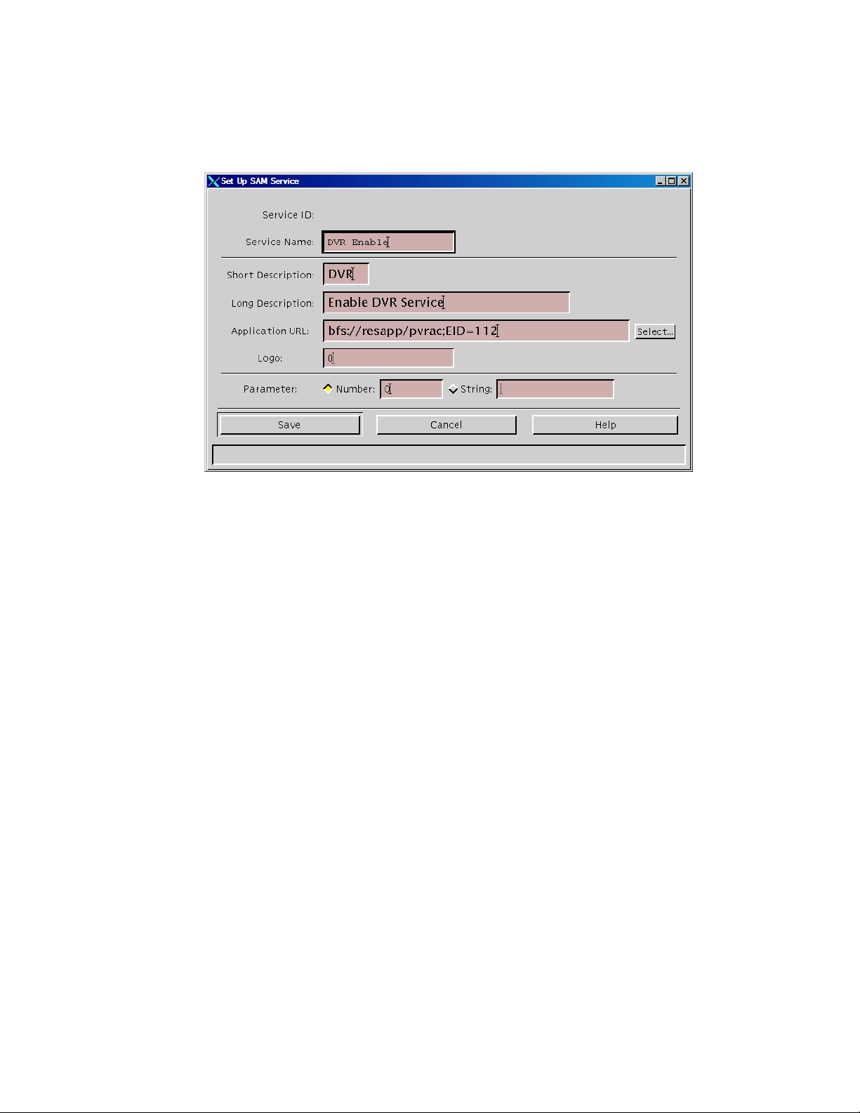
4 Follow these instructions to enter data in the fields of the Set Up SAM Service
window:
Service Name: Enter a name for the DVR service, such as DVR Enable.
Short Description: Enter a short description (up to 5 alphanumeric
characters) for the DVR service, such as DVR. Subscribers see the short
description in the channel banner when DVR service is activated.
Long Description: Enter a long description (up to 32 alphanumeric
characters) for the DVR service. This information is for your use only.
Subscribers will not see the text that you enter here.
Application URL: Enter one of the following URLs according to how you
want to offer this service:
– Open access (global method): To offer the DVR service to all subscribers
who have a DVR, enter bfs://resapp/pvrac.
– Controlled access (package method): To limit the DVR service only to
subscribers who have a DVR and who are authorized for the DVR
package, enter bfs://resapp/pvrac;EID=#, replacing the # symbol with the
decimal equivalent of the EID for the DVR package.
Note: To obtain decimal equivalent of the EID, refer to step 13 of Adding
a DVR Package to the DNCS (on page 3).
Page 14
Chapter 1 Enabling DVR Service
6 4011411 Rev B
Logo: If you have a custom logo that you want to use for this service, enter
the logo ID for the desired logo. Otherwise, enter 0 (zero).
Parameter: Click the Number option and then enter 0 in the Number field.
5 Click Save to save the service information in the DNCS database and close the
Set Up SAM Service window. The SAM Service List window updates to include
the new service with its system-assigned service ID and application URL tag.
6 Record the service name here: __________________________________.
Note: You need this name as you continue to set up the service.
7 Add DVR service to Channel Maps. Go to Adding the DVR Service to Channel
Maps (on page 7).
Page 15
Adding the DVR Service to Channel Maps
4011411 Rev B 7
Adding the DVR Service to Channel Maps
This section describes how to add the DVR service to channel maps so that
subscribers who are authorized for DVR service can access the service.
After you have registered the DVR service with the SAM, follow these instructions
to add the DVR service to appropriate channel maps.
Notes:
After DVR service has been added to channel maps, DVRs display a generic DVR
service screen whenever subscribers tune to the DVR channel. However, you can
customize DVR service so that DVRs display the Recorded List whenever
subscribers tune to the DVR channel. For more information, go to Customizing
DVR Services (on page 11).
Non-DVRs without the DVR package display a Not Authorized barker whenever
subscribers tune to the DVR channel. Non-DVRs with the DVR package display a
black screen when subscribers tune to the DVR channel.
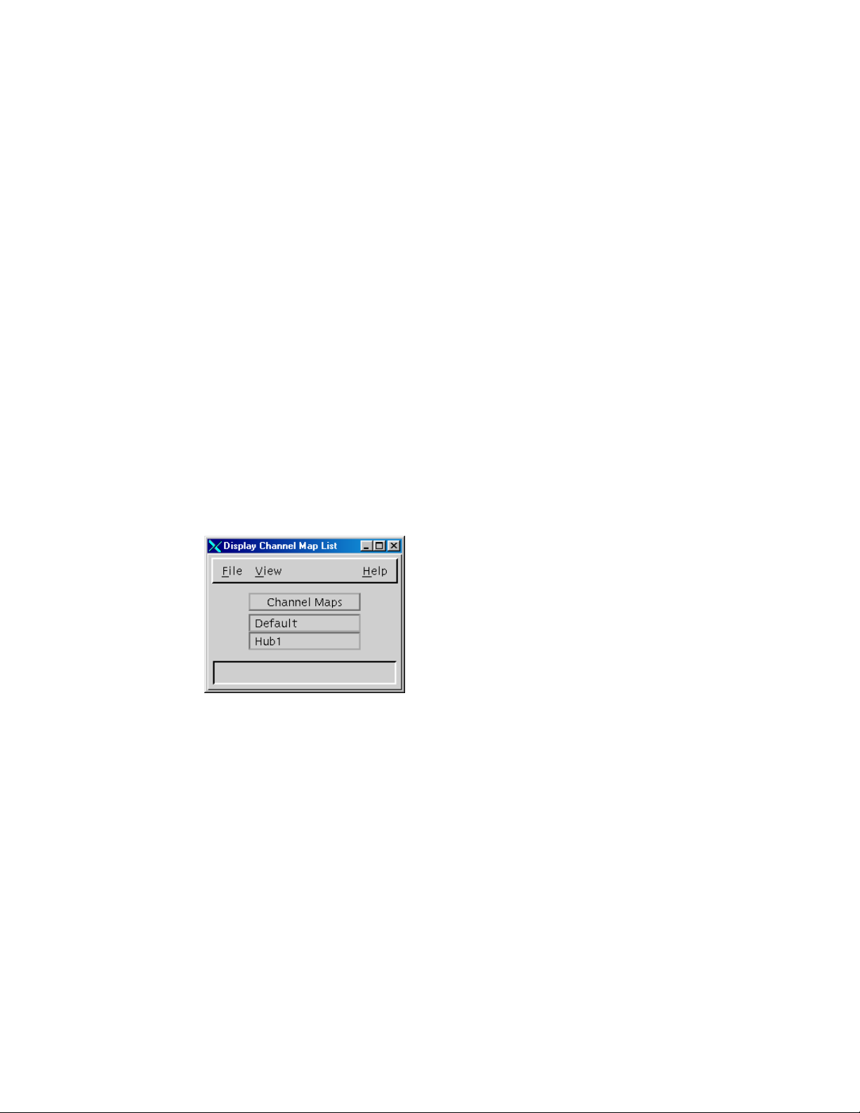
1 On the DNCS Administrative Console, click the Application Interface Modules
tab.
2 Click Channel Maps. The Display Channel Map List window opens.
3 Click once on the row that contains the channel map to which you want to add
this service.
Page 16
Chapter 1 Enabling DVR Service
8 4011411 Rev B
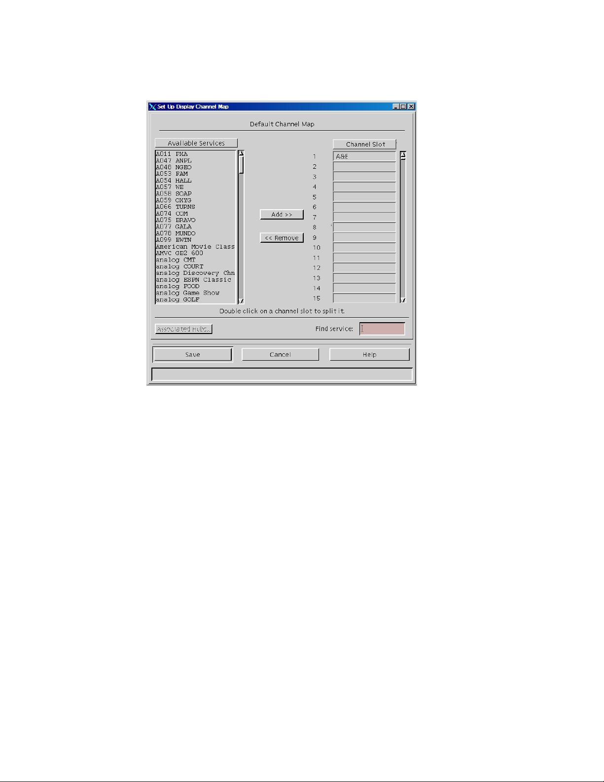
4 Click File, and then select Open. The Set Up Display Channel Map window
opens for the channel map you selected.
5 Scroll through the Available Services field until you see the DVR service listed,
and then click the DVR service to select it.
6 Scroll through the Channel Slot field until you see the channel slot to which you
want to assign the DVR service, and then click the channel slot to select it.
7 Click Add. The DVR service moves from the Available Services field to the
Channel Slot field you selected.
8 Click Save to save the channel map information in the DNCS database and close
the Set Up Display Channel Map window. By default, the system waits 20
minutes to build new channel maps. However, the amount of time that elapses
between a change to a channel map and the time that a new channel map is built
and broadcast to DHCTs varies according to the SAM Update Timer setting. For
this reason, allow an appropriate amount of time to pass before testing DVR
service to verify that channels were added.
9 Repeat steps 3 to 8 for each channel map that requires DVR service, and then go
to step 10.
Page 17

Adding the DVR Service to Channel Maps
4011411 Rev B 9
10 On the Display Channel Map List window, click File, and then select Close to
close the window and return to the DNCS Administrative Console.
11 Now that you have successfully enabled DVR service, continue preparing the
DVR service for use in one of the following ways:
If you want to customize DVR service so that it meets your business needs,
go to Customizing DVR Services (on page 11).
If you do not want to customize DVR service and will use the default
settings, go to Testing DVR Services (on page 37).
Note: For a description of the DVR service default settings, go to Customizing
DVR Services (on page 11).
Page 18

Page 19

4011411 Rev B 11
Introduction
2 Chapter 2
Customizing DVR Services
This chapter describes the default settings for DVR services and
describes the different ways you can customize these settings. This
chapter also provides instructions for configuring your system to
support each customized setting.
In This Chapter
Ways to Customize DVR Service ........................................................ 12
Record from Quick Settings Menu: Allow Subscribers to
Record a Program from the Quick Settings Menu ........................... 16
Recording Control: Prevent Subscribers from Recording a
Service..................................................................................................... 17
DVR Channel Display: Display the Recorded List when
Tuning to the DVR Channel ................................................................ 19
First Runs Recording Option: Allow Subscribers the Option to
Record First Runs of a Program, Not Reruns ................................... 21
Power Save: Disable the Power Save Feature ................................... 26
Stand-Alone Authorization: Authorize DVRs for Stand-Alone
Mode ....................................................................................................... 28
Enable Block Title: Prevent Titles of Recordings Blocked by
the Parental Control Feature From Showing .................................... 34
Page 20
Chapter 2 Customizing DVR Services
12 4011411 Rev B
Ways to Customize DVR Service
Tables in this section describe the ways you can customize the behavior of DVR
services. To customize a behavior shown in these tables, refer to the appropriate
procedure that appears later in this chapter.
Custom DVR Behaviors
The following table describes the ways that you can customize the behavior of the
DVR Behavior Default Behavior Custom Behavior
DVR service to meet your business needs.
Subscriber Impact
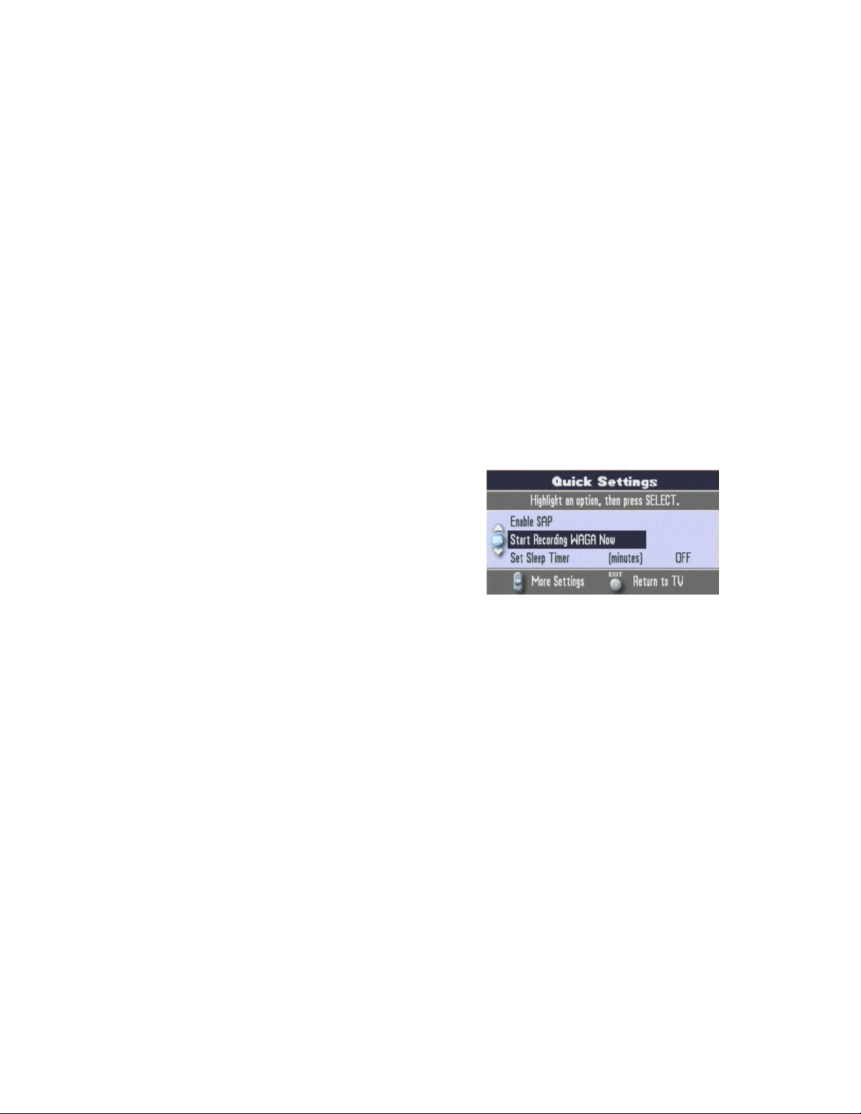
Record From Quick
Settings Menu
Recording Control
The default behavior of the DVR
service does not provide a recording
option in the Quick Settings menu.
Subscribers who have a DVR can
automatically record most services
when the DVR service has been set
up properly. Applications such as
video-on-demand (VOD) cannot be
recorded.
When customized, a recording option
appears in the Quick Settings menu,
similar to the example shown here.
When customized, you can prevent
subscribers from recording a specific
service, such as VOD. When
customized, the following message is
displayed when subscribers attempt to
record a non-recordable service:
ATTENTION: Recording feature not
available on this channel.
Page 21
Ways to Customize DVR Service
4011411 Rev B 13
Subscriber Impact
DVR Behavior Default Behavior Custom Behavior
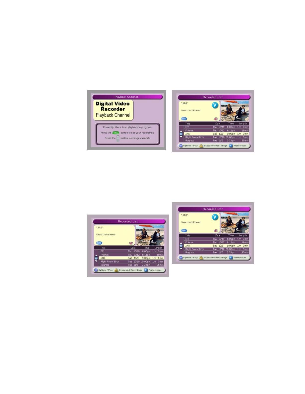
DVR Channel
Display
When subscribers tune to the
channel that provides DVR service, a
generic DVR service screen displays
as shown here.
When customized, the Recorded List
screen, as shown here, displays when
subscribers tune to the channel that
provides DVR service.
Custom Logo for
DVR Screens
(msologonotipg.rle)
Note: If a recording is playing on the
DVR service channel, the recording
is paused when a subscriber tunes to
the DVR service channel.
When a DVR screen displays (for
example, the Recorded List screen),
no logo appears in the Information
area of the screen, as shown in the
following example.
When customized, the configured logo
appears in the Information area on the
DVR screen, as shown here.
Note: To customize this feature, refer
to LogoTool Software User's Guide (part
number 4000820) and Configuring
Logos on the DNCS (part number
738163).
Page 22

Chapter 2 Customizing DVR Services
14 4011411 Rev B
DVR Behavior Default Behavior Custom Behavior
First Runs
Recording Option
(_FRDA SAM
service)
Power Save Feature
From the All Episode Recording
Options screen, subscribers can
record all episodes (first-run and
rerun episodes) by selecting any of
the following options from the All
Episode Recording Options screen:
On this channel at any time
On this channel, this day, and in
this time slot
On this channel, any day, and in
this time slot
By default, the Power Save feature is
enabled for DVR service. When this
feature is enabled, a DVR spins
down the hard disk drive and
activates a screen saver after any 15
minute period of inactivity that
occurs between 1 a.m. and 6 a.m.
Subscriber Impact
When customized, the First Run only
on this channel option is added to the
All Episode Recording Options screen,
as shown in the following example.
Selecting this option allows
subscribers to record first runs (new
episodes) of a selected program on a
particular channel.
When customized, the Power Save
feature is disabled for a DVR.
To disable the Power Save feature,
contact Cisco Services for assistance.
Screen-Saver Logo
(ssmsologo.rle)
When in spin-down mode, DVRs
display a black screen with the
message Press any remote key to
continue watching TV. This
message moves every 10 seconds to
prevent screen burn in.
When enabled, the configured logo
appears above the default message, as
shown in the following example. The
logo and message move every 10
seconds to prevent screen burn in.
Note: To enable this feature, refer to
LogoTool Software User's Guide (part
number 4000820) and Configuring
Logos on the DNCS (part number
738163).
Page 23

Ways to Customize DVR Service
4011411 Rev B 15
Subscriber Impact
DVR Behavior Default Behavior Custom Behavior
Stand-Alone
Authorization
By default, a DVR is not authorized
for stand-alone mode. As a result,
DVRs cannot play recordings unless
they are connected to a DBDS
network. Because they must be
connected to the DBDS network to
play recordings, subscribers cannot
take DVRs with them when away
from home and use the DVRs to
When customized, DVRs are
authorized for stand-alone mode. As a
result, subscribers are able to play
DVR recordings without an active,
two-way connection to the DBDS
network. These subscribers are able to
take their DVRs with them when
away from home and use the set-tops
to watch recordings.
watch recordings.
Title Block
Note: The default
setting for this
feature is disabled.
When disabled,
DVRs show the titles
of programs that
have been blocked
by the Parental
Control feature. SR
2.7/ 3.7 or 4.2 allows
you to change this
default.
When this feature is disabled, the
SARA client allows the titles of
recordings that have been blocked
by the Parental Control feature to
show in the Recorded List,
Scheduled Recordings, Recorded
Program Options, and IPG screens.
When customized, the SARA client
prevents the titles of any recordings
that have been blocked by the Parental
Control feature from showing in the
Recorded List, Scheduled Recordings,
Recorded Program Options, and IPG
screens. Instead, Title Blocked
displays for the title of the recording.
Page 24

Chapter 2 Customizing DVR Services
16 4011411 Rev B
Record from Quick Settings Menu: Allow Subscribers to Record a Program from the Quick Settings Menu
This section describes how to customize the DVR service so that subscribers can
record a currently tuned program from the Quick Settings menu. Adding this
selection to the Quick Settings menu gives subscribers another way to record a
currently tuned program. (Subscribers can also record a program by pressing the
RECORD key on the remote control or by selecting the program from the IPG.)
Allowing Subscribers to Record a Currently Tuned Program from the Quick Settings Menu
Most cable service providers configure their systems so that all DVRs in the system
use this custom behavior. However, a system can be configured so that only DVRs in
certain hubs use this custom behavior. For assistance configuring this custom
behavior for use by specific hubs, refer to Chapter 1 of Enhancing Your Subscribers'
Experience: SARA Configurable Options (part number 4002178).
1 On the DNCS Administrative Console, select the Server Applications tab.
2 Click DHCT Config. The DHCT Configure Prompt window opens.
3 To provide all DVRs in your system with this custom behavior, click Global. The
Set Up Global DHCT Configuration window opens.
4 Select the Quick Settings tab. The Quick Settings tab appears in the forefront.
5 If necessary, click the Has Record option to enable it.
Note: When the Has Record option is enabled, the selection box to the left of the
option is yellow. When enabled, subscribers have the option to record the
currently tuned program by selecting this option from the Quick Settings menu.
6 Click Save. The Application Server sends this custom behavior to all DVRs in
your system. As a result, subscribers with a DVR can record a currently tuned
program by either pressing the RECORD key on the remote control or by making
a selection from the Quick Settings menu.
7 Do you need to customize other aspects of DVR service?
If yes, continue customizing the service by following the appropriate
procedure in this chapter.
If no, verify that DVR service functions according to the customizations you
have made. Go to Testing DVR Services (on page 37).
Page 25

Recording Control: Prevent Subscribers from Recording a Service
4011411 Rev B 17
Recording Control: Prevent Subscribers from Recording a Service
Follow these instructions to customize the DVR service by disabling DVR
functionality for specific services so that subscribers cannot record them. Otherwise,
subscribers can record any service, even those on VOD and Music Channels.
When subscribers are prevented from recording a service, the following message
displays whenever a subscriber attempts to record the service:
ATTENTION: Recording feature not available on this channel
Important! You should disable the DVR functionality for any services that you do
not want subscribers to record.
Preventing Subscribers from Recording a Service
1 From the SAM Service List window, highlight the service that you do not want
subscribers to record.
2 Click File and then select Open. The Set Up SAM Service window opens with
information about the service you selected.
3 Modify the Application URL field by adding ;NOPVR to the end of the existing
URL, as shown in the following example. In this example, the URL
bfs://resapp/watchtv becomes bfs://resapp/watchtv;NOPVR.
4 Click Save to save the service information in the DNCS database and close the
Set Up SAM Service window. The SAM Service List window is now visible.
Page 26

Chapter 2 Customizing DVR Services
18 4011411 Rev B
5 Repeat steps 1 through 4 for every service that you do not want subscribers to
record.
6 Do you need to customize other aspects of DVR service?
If yes, continue customizing the service by following the appropriate
procedure in this chapter.
If no, verify that DVR service functions according to the customizations you
have made. Go to Testing DVR Services (on page 37).
Page 27

DVR Channel Display: Display the Recorded List when Tuning to the DVR Channel
4011411 Rev B 19
DVR Channel Display: Display the Recorded List when Tuning to the DVR Channel
This section describes how to customize the DVR service so that the Recorded List
displays instead of the default screen whenever subscribers tune to the DVR
channel. Otherwise, the generic DVR service screen displays whenever subscribers
tune to the DVR channel.
Displaying the Recorded List when Tuning to the DVR Channel
1 On the DNCS Administrative Console, click the Application Interface Modules
tab.
2 Click SAM Service. The SAM Service List window opens.
3 Click File, and then select New. The Set Up SAM Service window opens.
Page 28

Chapter 2 Customizing DVR Services
20 4011411 Rev B
4 Enter the following data in the fields of the Set Up SAM Service window so that
the window is similar to the following example.
Service Name: Recorded List Enable
Short Description: _RPL
Long Description: Enable the Recorded List
Application URL: dummyURL
Logo: 0 (zero)
Parameter: Number: 0
5 Click Save to save the service information in the DNCS database and close the
Set Up SAM Service window. The SAM Service List window updates to include
the new service with its system-assigned service ID and application URL tag. As
a result, the Recorded List now displays whenever subscribers tune to the DVR
channel.
6 Do you need to customize other aspects of DVR service?
If yes, continue customizing the service by following the appropriate
procedure in this chapter.
If no, verify that DVR service functions according to the customizations you
have made. Go to Testing DVR Services (on page 37).
Page 29

First Runs Recording Option: Allow Subscribers the Option to Record First Runs of a Program, Not Reruns
4011411 Rev B 21
First Runs Recording Option: Allow Subscribers the Option to Record First Runs of a Program, Not Reruns
This section describes how to customize the DVR service to support the First Runs
feature so that subscribers have the option to record first runs (new episodes) of a
program and not record reruns. For example, a subscriber could record all new
episodes of "CSI: Miami" that are shown on a particular channel, but not record "CSI:
Miami" episodes that have already been broadcast.
In order to support the First Runs feature, you must customize the All Episodes
Recording Options screen to display the First run only on this channel option. If
you do not customize this screen, this option does not appear on the screen.
This section also describes how to use the IPG editor to verify that the data provider
is flagging reruns appropriately. Ensuring that reruns are flagged appropriately is
important because the Program Guide identifies programs not flagged as reruns by
placing a first run (NEW) icon beside the program. Because the First Runs recording
feature records only programs idenfied with the NEW icon, the First Runs recording
feature may not perform as expected. Using the IPG editor for verification ensures
that the First Runs feature will perform as expected.
Checking for Rerun Feature Support
Follow these instructions to check that the data provider is flagging programs
appropriately to support the First Runs feature.
1 On the DNCS Administrative Console, click the Application Interface Modules
tab.
2 Click IPG.
3 Select the collector that you use to gather IPG data.
Note: Most systems use the IPG_ENG collector.
4 Click File and select Program Data.
5 In the date fields, enter a date when you know a rerun is broadcast and click Get
Data From Database.
6 Select a program that you know is a rerun.
Important: You should check with your data providers to make certain that you
understand when they set the rerun feature for a program. For example, they
may not set the feature for a program in syndication. Understanding when your
data provider sets this feature is essential to setting expectations about what
content will be recorded.
7 Click File and select Open.
8 Select the Features tab.
Page 30

Chapter 2 Customizing DVR Services
22 4011411 Rev B
Important: Be aware that not all IPG data providers support the Rerun flag.
When this occurs, all episodes of a program (first runs and reruns) will be
identified as first runs and will display the NEW icon. As a result, when
subscribers use the First Runs recording feature, all episodes of the selected
program will be recorded because this feature records any episodes of a selected
program flagged with the NEW icon.
When Rerun is not selected,
as shown here, the first run
(NEW) icon appears in the
Program Guide beside the
program.
9 Is Rerun selected?
If yes, repeat this procedure for several programs to ensure that the data
provider is consistently enabling this feature. When you are satisfied that the
data provider is sending the correct data, go to Allowing Subscribers the
Option to Record First Runs of a Program, Not Reruns (on page 23).
If no, contact the data provider to investigate why Rerun is not selected.
Page 31

First Runs Recording Option: Allow Subscribers the Option to Record First Runs of a Program, Not Reruns
4011411 Rev B 23
Allowing Subscribers the Option to Record First Runs of a Program, Not Reruns
To allow subscribers the option to record first runs (new episodes) of a selected
program on a particular channel, enable first run filtering.
Important: If your IPG data provider does not support the Rerun flag, do not use
this procedure. Otherwise, all episodes of a program (first runs and reruns) will be
identified as first runs and will display the NEW icon. As a result, when subscribers
use the First Runs recording feature, all episodes of the selected program will be
recorded because this feature records any episodes of a selected program flagged
with the NEW icon.
This section provides instructions for enabling first run filtering using either of the
following methods:
Open access (global method) — Enables first run filtering for all subscribers
who have a DVR
Conditional access (package method) — Enables first run filtering for only those
subscribers who have been authorized for the FRDA (first run data available)
package and who have a DVR
Before You Begin
If you are enabling first run filtering with conditional access, make certain that you
know the package name that your billing system uses to enable or disable this
feature. If you do not know the name, contact your billing system operator to obtain
the correct package name.
Task Overview
The following tasks summarize how to enable DVR service with conditional access.
Note: The rest of this section provides detailed instructions for the tasks summarized
below.
1 To enable first run filtering with conditional access, add an FRDA package to the
DNCS.
Note: If enabling this feature with global access, it is not necessary to add an
FRDA package to the DNCS.
2 Add an FRDA service to the SAM.
Page 32

Chapter 2 Customizing DVR Services
24 4011411 Rev B
Adding an FRDA Package to Conditionally Enable First Run Episode Filtering
Follow these instructions to add an FRDA package to the DNCS.
Important: For this feature to function, the IPG content provider must set the rerun
flag correctly. See Checking for Rerun Feature Support (on page 21) for more
information.
1 Do you want to provide this feature to only subscribers who are authorized for
the FRDA package?
If yes, go to step 2.
If no, go to Adding an FRDA Service to the SAM (on page 25).
2 On the DNCS Administrative Console, click the DNCS tab and then select the
System Provisioning tab.
3 Click Package. The Package List window opens.
4 Does an FRDA package appear in the Package List window?
If yes, an FRDA package has already been added to the DNCS. Go to step 7.
If no, click the File menu and select New. The Set Up Package window
opens.
5 Follow these instructions to enter data in the Set Up Package window:
Package Name: Enter the package name that your billing system uses to
enable the First Runs recording option. The name that you enter here must
exactly match the package name that your billing system uses.
Note: If necessary, contact your billing system operator to obtain the correct
package name.
Duration: Leave the default value of Unlimited.
6 Click Save to save this package in the DNCS database and close the Set Up
Package window. The package appears in the Package List window.
7 From the Package List window, select the package you will use to provide
subscribers with the First Runs recording option.
8 Click File, and then select Open. The Set Up Package window opens for the
package you selected.
9 Record the number shown in the EID field here: _________________________
Note: The number shown in the EID field is in hexadecimal format.
10 Click Cancel to close the Set Up Package window and return to the Package List
window.
11 Click File and then select Close to close the Package List window and return to
the DNCS Administrative Console.
12 Refer to the hexadecimal conversion table in EID Conversion Table (on page 55)
to convert the EID from hexadecimal format to decimal format, and then write
the decimal format of the EID here: ____________________
13 Go to Adding an FRDA Service to the SAM (on page 25).
Page 33

First Runs Recording Option: Allow Subscribers the Option to Record First Runs of a Program, Not Reruns
4011411 Rev B 25
Adding an FRDA Service to the SAM
The Application URL that you enter when creating a SAM FRDA service determines
whether the service uses the open (global) or conditional (package) access. The
following procedure can be used for either method.
Important: For this feature to function, the IPG content provider must set the rerun
flag correctly.
1 On the DNCS Administrative Console, click the Application Interface Modules
tab.
2 Click SAM Service. The SAM Service List window opens.
3 Click File, and then select New. The Set Up SAM Service window opens.
4 Enter the following data in the fields of the Set Up SAM Service window:
Service Name: First Run Filter
Short Description: _FRDA
Note: FRDA is an abbreviation of First Run Data Available.
Long Description: First Run Filter
Application URL: Enter one of the following URLs according to how you
want to provide this service to subscribers:
– Open access (global method): To provide all subscribers who have a
DVR with this feature, enter dummyURL.
– Controlled access (package method): To provide this feature only to
subscribers who have a DVR and who are authorized for the FRDA
package, enter dummyURL;EID=#, replacing the # symbol with the
decimal equivalent of the EID for the FRDA package.
Note: To obtain this number, refer to step 12 of the previous procedure,
Adding an FRDA Package to Conditionally Enable First Run Episode
Filtering (on page 24).
Logo: 0 (zero)
Parameter: Number: 0
5 Click Save to save this service information in the DNCS database and close the
Set Up SAM Service window. The SAM Service List window updates to include
the new service with its system-assigned service ID and application URL tag. As
a result, the "New first-run episodes on this channel" option is added to the All
Episodes Recording Option screen, and subscribers have the option to record
first runs (new episodes) of a selected program on a particular channel.
6 Do you need to customize other aspects of DVR service?
If yes, continue customizing the service by following the appropriate
procedure in this chapter.
If no, verify that DVR service functions according to the customizations you
have made. Go to Testing DVR Services (on page 37).
Page 34

Chapter 2 Customizing DVR Services
26 4011411 Rev B
Power Save: Disable the Power Save Feature
This section briefly describes the Power Save feature and provides instructions for
using either of the following methods to disable the Power Save feature:
Disabling with conditional access — Using the conditional access method to
disable the Power Save feature allows you to disable the feature for an individual
DVR. This method is recommended for all set-top types and is required for
disabling the Power Save feature on set-tops that use DVR Releases 1.1.6a5 to
1.4.0.
Disabling with global access — Using the global access method to disable the
Power Save feature allows you to disable this feature for all DVRs in your
system. This method is required for all set-tops that use DVR Release 1.4.2 and
later.
What is the Power Save Feature?
The Power Save feature is intended to increase the life expectancy of DVRs. When
the Power Save feature is enabled, the SARA client starts monitoring for user activity
beginning at 1 a.m. If no activity is detected for 10 minutes, the client displays a
message that notifies the subscriber that their DVR will automatically enter powersave mode in 5 minutes.
After the additional 5 minutes elapse with no user activity, the Power Save feature
spins down the hard disk drive in the DVR and activates a screen saver feature. (In
releases prior to DVR 1.5.2, the Power Save feature behaves differently following 5
additional minutes of inactivity.)
Note: The mechanism used to disable spin down was changed in DVR release 1.4.2.
As a result, the spin down feature will be enabled after the upgrade from older DVR
releases.
However, if a subscriber is actively using the DVR (for example, presses any key on
the remote or any button on the front panel at least once every 2 hours), the set-top
will continue to operate normally and the Power Save feature will not activate. Even
after powering off the set-top or spinning down the hard drive, scheduled
recordings will occur.
Page 35

Power Save: Disable the Power Save Feature
4011411 Rev B 27
Disabling the Power Save Feature
Cisco strongly recommends that you leave the Power Save feature enabled.
However, if you have some subscribers who request that the Power Save feature be
disabled, we can provide a mechanism for you to disable the feature. Contact Cisco
Services for assistance.
Important: Sites using the Pioneer Passport or other resident applications should
contact their application vendor for information on how their application allows for
hard disk spin down and power saving on the DVR.
Page 36

Chapter 2 Customizing DVR Services
28 4011411 Rev B
Stand-Alone Authorization: Authorize DVRs for Stand-Alone Mode
This section provides a description of the stand-alone mode and summarizes the
process that enables and disables a DVR for stand-alone mode. This section also
provides instructions for authorizing DVRs for stand-alone mode.
Important: Stand-alone mode is supported in DVR Release 1.5 and later. For more
information, refer to Guide to Using Your Digital Video Recorder in Stand-Alone Mode
(part number 4011416).
What is Stand-Alone Mode?
Stand-alone mode allows subscribers to play DVR recordings without an active
connection to a DBDS network. Subscribers who want to use their DVR to watch
recordings while away from home will enjoy this feature.
To take advantage of the stand-alone feature, subscribers need their DVR, a TV, and
cables to connect the DVR to the TV.
To notify subscribers that the DVR is in stand-alone mode, the SARA client displays
the following barker.
When in stand-alone mode, all DVR controls (such as pause, reverse, and fastforward) are available for controlling recordings in the Recorded List.
Note: When a DVR is in stand-alone mode and the Guide key is pressed, the SARA
client displays a barker indicating that the program guide is unavailable.
Page 37

Stand-Alone Authorization: Authorize DVRs for Stand-Alo ne Mode
4011411 Rev B 29
How Is Stand-Alone Mode Enabled?
Before a DVR can be placed in stand-alone mode, the set-top must first be authorized
for stand-alone mode with a Stand-Alone package from the headend. Once
authorized, the absence of system information (SI) data on the forward data channel
(FDC) tells the client to enable stand-alone mode for set-tops authorized with the
Stand-Alone package.
The headend authorizes a DVR for stand-alone mode by
sending a Stand-Alone package to the DVR.
The client receives the package authorizing it for stand-alone
mode and stores a stand-alone authorization flag in nonvolatile
memory (NVM).
The subscriber powers down and disconnects the DVR so that it
can be moved from its current location. As part of the
disconnection process, the RF cable is disconnected from the
CABLE IN port on the back of the set-top so that the set-top
cannot communicate with the DBDS network.
When the set-top is in its new location, the subscriber connects
the set-top to the TV, connects the TV and set-top to a power
source, and presses the Power button on the front panel of the
set-top to reboot the set-top.
When the set-top reboots, the client begins a timer to determine
if the set-top is connected to the headend. If the client finds no SI
data within the timer period, the client checks the NVM for the
authorization flag.
If the client finds the flag set for authorization, it enters
standalone mode and displays the barker shown to the left to
notify the subscriber that the DVR is now in stand-alone mode.
Note: Whenever the Guide key is pressed and the DVR is in
stand-alone mode, the SARA client displays a barker indicating
that the program guide is unavailable.
Page 38

Chapter 2 Customizing DVR Services
30 4011411 Rev B
How Is Stand-Alone Mode Disabled?
As described in the following section, the presence of SI on the FDC tells a DVR that
has been authorized for stand-alone mode to disable stand-alone mode.
When the set-top reboots, the client begins a timer to determine if the set-top is
connected to the DBDS network. If the client finds SI data within the timer period, it
checks the network settings for a stand-alone authorization. If the network setting
does not match the setting stored in client's NVM, the client synchronizes the NVM
stand-alone flag to match the stand-alone authorization as indicated by the network,
and then disables the stand-alone mode.
When the set-top has been relocated to its
original location, the subscriber makes the
proper connections to connect the set-top to
home entertainment devices. As part of this
process, the following connections are
made:
The RF cable is reconnected to the
CABLE IN port on the back of the DVR
so that the DVR can communicate with
the DBDS network.
The power cord is connected to an AC
power source, which causes the DVR to
reboot.
How Do I Authorize a DVR for Stand-Alone Mode?
This section summarizes the process required to authorize a set-top for stand-alone
mode. For detailed instructions, start with Adding a Package to Control Subscriber
Access to the Stand-Alone Mode (on page 31).
1 If the service provider offers the stand-alone feature to subscribers separately
from other services, add a package for stand-alone authorization to the DNCS.
Go to Adding a Package to Control Subscriber Access to the Stand-Alone Mode
(on page 31).
Important:
When adding the package, make certain that the package name exactly
matches the package name that the billing system uses. Otherwise, the standalone feature will not function properly.
When offering the stand-alone feature to subscribers, cable service providers
may bundle the feature with another package-controlled feature, such as
DVR service. If this is the case, you do not need to add a package for standalone authorization to the DNCS and can use the DVR package.
2 Add a stand-alone service to the SAM. Go to Adding the Stand-Alone Service to
the SAM (on page 32).
Page 39

Stand-Alone Authorization: Authorize DVRs for Stand-Alone Mode
4011411 Rev B 31
Important: When adding the stand-alone service, you must use _SCIW for the
short description. Otherwise, the stand-alone feature will not function properly.
(SCIW is an abbreviation for Stand-Alone Cabin-In-the-Woods.)
Adding a Package to Control Subscriber Access to the Stand-Alone Mode
This section describes how to add a Stand Alone package to the DNCS.
When offering the stand-alone feature to subscribers, service providers may bundle
the feature with another package-controlled feature, such as DVR service. If this is
the case, you do not need to add a package for stand-alone authorization to the
DNCS because the DVR package can be used to control subscriber access to both
DVR service and the stand-alone feature. As a result, you do not need to complete
this procedure.
However, if the cable service provider offers the stand-alone feature to subscribers
separately from other services, follow this procedure to add a stand-alone package to
the DNCS.
Important: If you are authorizing a DVR for stand-alone mode, make certain that
you know the package name that your billing system will use to authorize this
feature. If you do not know the name, contact your billing system operator to obtain
the correct package name.
Adding a Package to Control Subsc r iber Access to the Stand-Al one Service
1 On the DNCS Administrative Console, click the DNCS tab and then select the
System Provisioning tab.
2 Click Package. The Package List window opens.
3 On the File menu, select New. The Set Up Package window opens.
4 Follow these instructions to enter data in the Set Up Package window:
Package Name: Enter the package name that your billing system uses to
enable Stand-Alone authorization. The name that you enter here must exactly
match the package name that the billing system uses. Otherwise, the standalone feature will not function properly.
Note: If necessary, contact your billing system operator to obtain the correct
package name.
Duration: Leave the default value of Unlimited.
5 Click Save. The Set Up Package window closes and the package you created
appears in the Package List window.
6 Scroll through the Package Name list and find the new package listed there.
7 Select the Stand-Alone package.
8 Click File, and then select Open. The Set Up Package window opens for the
package you selected.
9 Record the number shown in the EID field here: _________________________
The number shown in the EID field is in hexadecimal format.
Page 40

Chapter 2 Customizing DVR Services
32 4011411 Rev B
10 Click Cancel to close the Set Up Package window and return to the Package List
window.
11 Click File and then select Close to close the Package List window and return to
the DNCS Administrative Console.
12 Refer to the hexadecimal conversion table in EID Conversion Table (on page 55)
to convert the EID from hexadecimal format to decimal format, and then write
the decimal format of the EID here: ____________________
13 Go to Adding the Stand-Alone Service to the SAM (on page 32).
Adding the Stand-Alone Service to the SAM
1 On the DNCS Administrative Console, click the Application Interface Modules
tab.
2 Click SAM Service. The SAM Service List window opens.
3 Click File and then select New. The Set Up SAM Service window opens.
4 Follow these instructions to enter data in the fields of the Set Up SAM Service
window:
Service Name: Enter a name for the service, such as Stand-Alone.
Short Description: Enter _SCIW.
Important: You must enter _SCIW for the Short Description. Otherwise, your
system will be unable to support stand-alone authorization.
Long Description: Enter a long description for the stand-alone feature, such
as Stand-Alone Authorization. This information is for your use only.
Subscribers will not see the text that you enter here.
Note: You can enter up to 32 alphanumeric characters.
Application URL: Enter dummyURL;EID=#, replacing the # symbol with
the decimal equivalent of the EID belonging to the Stand-Alone package.
Notes:
– To obtain this number, refer to step 12 of Adding a Package to Control
Subscriber Access to the Stand-Alone Mode (on page 31).
– Entering this number limits Stand-Alone authorization only to
subscribers authorized for the stand-alone package.
Page 41

Stand-Alone Authorization: Authorize DVRs for Stand-Alone Mode
4011411 Rev B 33
Logo: If you have a custom logo that you want to use for this service, enter
the logo ID for the desired logo. Otherwise, enter 0 (zero).
Parameter: Click the Number option and then enter 0 in the Number field.
5 Click Save to save the service information in the DNCS database and close the
Set Up SAM Service window. The SAM Service List window updates to include
the new service with its system-assigned service ID and application URL tag.
DVRs are now authorized for stand-alone mode.
6 Do you need to customize other aspects of DVR service?
If yes, continue customizing the service by following the appropriate
procedure in this chapter.
If no, verify that DVR service functions according to the customizations you
have made. Go to Testing DVR Services (on page 37).
Page 42

Chapter 2 Customizing DVR Services
34 4011411 Rev B
Enable Block Title: Prevent Titles of Recordings Blocked by the Parental Control Feature From Showing
This section describes how to enable the Block Title feature so that the SARA client
prevents the titles of recordings that have been blocked by the Parental Control
feature from showing in the Recorded List, Scheduled Recordings, and Recorded
Program Options screens. When this feature is enabled, the words "Blocked Title"
display in these screens instead of the program title.
The factory setting for this feature is disabled. When disabled, DVRs show the titles
of programs that have been blocked by the Parental Control feature.
Note: In earlier releases, this setting was configurable from the General Settings
menu. In SR 2.7/3.7 and 4.2 and later, this setting is also configurable from the
DNCS.
Configuring DVRs to Prevent Titles of Recordings Blocked by the Parental Controls Feature From Showing
Use one of the following methods to enable the Block Title setting. When this setting
is enabled, the SARA client prevents the titles of recordings that have been blocked
by the Parental Control feature from showing in the Recorded List, Scheduled
Recordings, and Recorded Program Options screens:
Staging Defaults Method — Enable the Block Title feature for DVRs that are
being staged.
Addressable Method — Enable the Block Title feature for a single DVR.
Using the Staging Default Method to Prevent Titles of Recordings Blocked by the Parental Controls Feature From Showing
1 On the DNCS Administrative Console, select the Server Applications tab.
2 Click DHCT Config. The DHCT Configure Prompt window opens.
3 Click Staging Defaults. The Set Up Staging Defaults window opens with the
Base Application tab in the forefront.
4 Click the IPG tab. The IPG tab comes to the forefront.
5 Click to enable the setting Block Titles of Blocked Programs.
6 Click Save. When DVRs are staged, they will function with the Blocked Title
feature enabled.
Page 43

Enable Block Title: Prevent Titles of Recordings Blocked by the Parental Control Feature From Showing
4011411 Rev B 35
Using the Addressable Method to Enable the Block Title Setting
Important: To complete this procedure successfully, you must have the MAC
address of the DVR whose setting you want to enable.
1 On the DNCS Administrative Console, select the Server Applications tab.
2 Click DHCT Config. The DHCT Configure Prompt window opens.
3 Click Addressable. The Set Up Addressable DHCT Configuration window opens
with the Base Application tab in the forefront.
4 Type the MAC Address in the DHCT MAC Address field.
5 Select the IPG tab. The IPG tab moves to the forefront.
6 On the IPG tab, click to enable the setting Block Titles of Blocked Programs. The
Block Titles of Blocked Programs box changes from gray to yellow and the
setting is shown in bold to indicate that it has been changed from its original
setting and that it will be sent to the DVR.
Note: Because all changed settings are sent to the DVR, settings remain in bold
even if they are changed back to their original settings.
7 Click Send. The SARA server sends the new setting to the DVR that you
specified.
8 Do you need to customize other aspects of DVR service?
If yes, continue customizing the service by following the appropriate
procedure in this chapter.
If no, verify that DVR service functions according to the customizations you
have made. Go to Testing DVR Services (on page 37).
Page 44

Page 45

4011411 Rev B 37
Introduction
3 Chapter 3
Testing DVR Services
Testing DVR Services ........................................................................... 40
This section describes how to test DVR services on a DVR in your
headend to ensure that each service functions according to your
customized settings.
In This Chapter
Before You Begin ................................................................................... 38
Quick Steps for Experienced Users .................................................... 39
Page 46

Chapter 3 Testing DVR Services
38 4011411 Rev B
Before You Begin
Before you begin, make sure that you have any one of the following for the DVR that
you will use to test DVR services:
MAC address
IP address
Serial number
Page 47

Quick Steps for Experienced Users
4011411 Rev B 39
Quick Steps for Experienced Users
Experienced users may prefer to follow these quick steps to test DVR services.
Users who require step-by-step instructions should go to Testing DVR Services (on
page 40).
1 Wait an appropriate amount of time for the system to broadcast channel map
and SAM changes to DHCTs before testing DVR services.
Note: Channel map and SAM changes are broadcast to DHCTs on a regular basis
according to the setting for the SAM Update Timer. The default time for the
timer setting is every 20 minutes. However, you can verify the amount of time
your system allows by checking the Update Timer setting in the SAM
Configuration window (DNCS Administrative Console > Applications
Interface Modules tab > SAM Config).
2 Provision a DVR in your headend for the DVR service.
Note: To provision a DVR, add the DVR package to the set-top in your headend.
3 Verify that the services function appropriately on the DVR you have provisioned
by testing each feature you have customized. For a list of customizations to
verify, go to Verifying the Service Setup (on page 41).
Page 48

Chapter 3 Testing DVR Services
40 4011411 Rev B
Testing DVR Services
This section provides detailed instructions for each of the following tasks required to
test DVR services:
Provision a DVR for the service as described in Provisioning a DVR for Services
(on page 40).
Test the DVR you have just provisioned to ensure that it functions according to
your customized behaviors. For details, see Verifying the Service Setup (on page
41).
Provisioning a DVR for Services
Follow these instructions to provision a DVR in your headend for all the services
you might test: DVR and stand-alone service.
1 Is your billing system able to add the packages for the services you are testing to
the DVR you are using for testing?
If yes, ask your billing system to add appropriate packages to the DVR you
are using for testing. After the billing system adds the packages, go to
Verifying the Service Setup (on page 41).
If no, click the DNCS tab on the DNCS Administrative Console.
2 Click the Element Provisioning tab.
3 Click DHCT. The DHCT Provisioning window opens, similar to the following
example.
Page 49

Testing DVR Services
4011411 Rev B 41
4 By default, the Open and By MAC Address options are already selected when
you open this window; therefore, click one of the following options, depending
on the information you have for the test DVR:
If you have the MAC address, click By MAC Address and enter the MAC
address of the DVR in the field to the right.
If you have the IP address, click By IP Address and then enter the IP address
of the DVR in the field to the right.
If you have the serial number, click By Serial Number and then enter the
serial number of the DVR in the field to the right.
5 Click Continue. The Set Up DHCT window opens for this DVR.
6 Click the Secure Services tab.
7 Scroll through the Available list and check all new package names.
8 Click Add. The packages that you selected move into the Selected list.
9 Click Save. The system updates the DVR to receive the packages and settings in
less than a minute.
10 Click Cancel to close the Set Up DHCT window and return to the DHCT
Provisioning window.
11 Click Cancel to close the DHCT Provisioning window and return to the DNCS
Administrative Console.
12 Now that you have provisioned the DVR in your headend for the services you
want to test, verify that the services function according to your customized
behaviors. Go to Verifying the Service Setup (on page 41).
V erifying the Service Setup
Follow these instructions to verify that you have successfully set up DVR services.
1 Make sure the DVR is connected to the television, as well as to an RF feed into
your network.
2 Power on the DVR.
3 Power on the television.
4 To verify that DVR service was successfully enabled, tune to any broadcast TV
channel for at least 20 seconds, and then press Rewind on the remote control.
Note: For information on using a DVR, refer to Getting Started With the Explorer
8300 and 8300HD DVR (part number 4004007) or Getting Started With the Explorer
8000 and 8000HD DVR (part number 740246).
5 Were you able to rewind to an earlier part of the live TV program?
If yes, you have successfully enabled DVR service. Go to step 6.
If no, contact Cisco Services for assistance.
Page 50

Chapter 3 Testing DVR Services
42 4011411 Rev B
6 Did you customize any DVR behaviors?
If yes, verify that DVR behaviors function according to your customizations.
Go to step 7.
If no, you are finished with this procedure.
7 Test the following DVR behaviors to verify that they function according to your
customizations:
Recording While Watching Behavior: Press on the remote control, or
select Record from the Quick Settings menu to verify that you can record a
currently tuned program.
DVR Channel Display Behavior: Tune to the DVR channel to verify that the
DVR displays the Recorded List screen and not the generic DVR screen.
Custom Logo Behavior (msologonotipg.rle): Press to display the
Recorded List screen and verify that the cable service provider logo appears
in the screen.
Recording Control Behavior: If you have prevented any service, such as a
Music Choice service from being recorded, tune to the channel where the
service is broadcast and attempt to record the service. The DVR should
prevent you from recording the service and should display the following
message: ATTENTION: Recording feature not available on this channel.
First Runs Recording Behavior: Set up the All Episodes feature to record an
episode that is being rerun. The DVR should not record an episode that is
being rerun.
Power Save Behavior: Verify that the test set-top remains powered on during
any 15-minute period of inactivity that occurs between 1 a.m. and 6 a.m.
Screen-Saver Logo Behavior: Verify that the cable service provider logo
appears on the Screen Saver during any 15-minute period of inactivity that
occurs between 1 a.m. and 6 a.m.
Stand-Alone Authorization Behavior: If the test DVR has no recordings
saved in the Recorded List, record some live TV so that a recording is saved
to the hard disk drive. Then disconnect the DVR from the DBDS network and
reboot it to verify that the Stand-Alone mode screen displays. Verify that you
can play a recording while disconnected from the DBDS network.
8 Does the DVR services function according to your customized behaviors?
If yes, you have successfully set up DVR services.
If no, contact Cisco Services for assistance.
Page 51

4011411 Rev B 43
4 Chapter 4
Supporting the Hard Disk
Drive Test
Introduction
This chapter begins by briefly describing the Hard Disk Drive (HDD)
test, the set-top models that support the test, and how to configure the
DNCS for the test. This overview is followed by procedures for setting
up the DNCS support the HDD test and instructions for verifying that
the procedures were performed successfully.
Finally, so that you have an idea of how the HDD test is used, the
process that staging technicians use to perform the HDD test is briefly
described.
In This Chapter
What Is the HDD Test? ........................................................................ 44
Setting Up the DNCS to Support the HDD Test .............................. 45
How Do Staging Technicians Use the HDD Test? ........................... 52
Page 52

Chapter 4 Supporting the Hard Disk Drive Test
44 4011411 Rev B
What Is the HDD Test?
This section briefly describes the HDD test, the set-top models that support the test,
and how to configure the DNCS for the test.
Note: The HDD test is an optional feature of the Staging Toolkit that is available in
the following DVR releases:
For Explorer 8000, 8010, 8240, and 8300 — DVR 1.5.2-1404 and later
For Explorer 8300HDC — DVR 1.5.3-0801 and later
Important! The Staging Toolkit is only available with the Cisco Resident Application
(SARA).
For instructions on using the Staging Toolkit, refer to Explorer
Communications Terminal Staging Guide (part number 734375).
The HDD test allows staging and installation technicians to determine the health of
hard drives in the following set-top models:
Explorer 8000 and 8000HD
Explorer 8240 and 8240HD
Explorer 8300 8300HD, and 8300HDC
What DNCS Changes Are Required to Support the HDD Test?
As the following procedure summarizes, to support the HDD test, an HDD Test
server must be added to the BFS. In addition, a file that contains hard-drive
performance specifications (testparam.cfg) must be placed on the BFS HDD Test
server so the file can be broadcast to set-tops. Without this file, set-tops are unable to
complete the HDD test.
The testparam.cfg file is located in the DNCS directory /dvs/resapp/Tools. The file
is installed during the CD installation of set-top software. If you did not install the
set-top software using a CD, or if this file is not present, contact Cisco Services.
®
Digital Home
Page 53

Setting Up the DNCS to Support the HDD Test
4011411 Rev B 45
Setting Up the DNCS to Support the HDD Test
Quick Steps for Experienced Users
The following steps summarize the tasks required to set up the BFS to support the
HDD test. Experienced users may prefer to follow this summary.
Users who require step-by-step instructions should go to Adding an HDD Test
Server to the BFS (on page 46).
Important Note for Multiple-Site (RCS-Enabled) Systems: Manually setting up any
BFS server or source must be done for the "AllSites" site only and not for any other
individual sites in your system. Otherwise, the server and source will fail.
1 Add a server with the following characteristics to the Servers tab of the BFS
Administration window.
Server Name: hddtest
Important: This field requires a specific entry. You must enter hddtest in
lowercase letters in this field. Otherwise, set-tops will not receive the
testparam.cfg file.
Selected Sources: Out of Band
Important: Multi-site (RCS-enabled) systems must add the server to only the Site
AllSites Administration window. Adding a server to the BFS Administration
window of individual sites and to the Site AllSites Administration window
causes the server to fail.
Note: To define these characteristics, display the Authorize BFS Server window
by following the quick path for your system configuration:
Single-site systems: DNCS Administrative Console > Application Interface
Modules tab > BFS Admin > Servers tab > File > New
Multi-site systems: DNCS Administrative Console > Application Interface
Modules tab > BFS Admin > File > All Sites > Servers tab > File > New
2 Register the server with the BFS Client by adding a server with the following
characteristics to the Broadcast File Server List window.
Server Name: hddtest
Mode: 2-way
Selected Sources: Out of Band
Important: Multi-site (RCS-enabled) systems must add the server to only the All
Sites Broadcast File Server List window. Adding a server to the Broadcast File
Server window of other individual sites and to the All Sites Broadcast File Server
List window prevents the system from setting up a server.
Page 54

Chapter 4 Supporting the Hard Disk Drive Test
46 4011411 Rev B
Note: To define these characteristics, display the Set Up Server window by
following the quick path for your system configuration:
Single-site systems: DNCS Administrative Console > Application Interface
Modules tab > BFS Client > File > New Server
Multi-site systems: DNCS Administrative Console > Application Interface
Modules tab > BFS Client > File > All Sites > File > New Server
3 Add the testparam.cfg file to the hddtest server in the BFS Client window.
Adding an HDD T est Server to the BFS
Note: This procedure can be used for systems that support multiple sites (RCSenabled) or single sites.
1 On the DNCS Administrative Console, select the Application Interface Modules
tab.
2 Click BFS Admin. Choose one of the following options:
For single-site systems, the Site DNCS BFS Administration window opens.
Click File and select All Sites.
For multiple-site (RCS-enabled) systems, the Please Select a Site window
opens.
3 Select the Servers tab.
4 Click File and select New. The Authorize BFS Server window opens.
5 Enter the following data into the fields of the Authorize BFS Server window:
In the Server Name field, enter hddtest.
From the Available Sources list, select Out of Band.
Click Add.
Result: The Authorize BFS Server window is configured as shown in the
following example.
Page 55

Setting Up the DNCS to Support the HDD Test
4011411 Rev B 47
6 Click Save to save your changes and close the Authorize BFS Server window.
The HDD Test server has been added to the BFS. As a result, the hddtest server
shows in the Server Name list, similar to the following example.
7 Click File and select Close to close the window.
8 Continue setting up the BFS to support the HDD Test by registering the HDD
Test server with the BFS client. Go to Registering the HDD Test Server with the
BFS (on page 49).
Page 56

Chapter 4 Supporting the Hard Disk Drive Test
48 4011411 Rev B
Verify That the HDD Test Serve r I s Successfully Set Up
This section provides instructions for using a local DVR with an HDD that is known
to be in good working order to verify that the HDD Test server has been set up
successfully. During this process, you are instructed to load the HDD test on a local
DVR and then run the HDD test on the DVR. A successful result indicates that the
HDD Test server has been set up correctly.
Before You Begin
Before you begin, make certain that the DVR you intend to use meets the following
specifications:
For Explorer 8000, 8010, or 8300 DVRs — DVR 1.5.2-1404 or later is installed on
the DVR.
For Explorer 8300HDC DVRs — DVR 1.5.3 or later is installed on the DVR.
The DVR is connected to your DBDS network.
The HDD is known to be in good operating order.
Quick Steps for Experienced Users
The following steps summarize the tasks required to verify that the HDD Test server
has been set up successfully. Experienced users may prefer to follow this summary.
Users who require step-by-step instructions should go to Verifying the Success of the
HDD Test Server (on page 48).
1 Reboot a DVR in your headend that meets the following specifications:
For Explorer 8000, 8010, or 8300 DVRs — DVR 1.5.2-1404 or later is installed
on the DVR.
For Explorer 8300HDC DVRs — DVR 1.5.3 or later is installed on the DVR.
The DVR is connected to your DBDS network.
The HDD is known to be in good operating order.
Result: When the DVR reboots, the SARA client reads the testparam.cfg file,
finds the appropriate entry for the DVR type, obtains the HDD performance
specifications for the DVR type, and stores this data in nonvolatile memory
(NVM).
2 Activate the Staging Toolkit, and then press the
HDD test utility. When the HDD test is complete, PASS appears in the DVR
display to indicate that the HDD meets performance specifications. If PASS does
not appear and you are confident that the HDD is in good operating order,
contact Cisco Services for assistance troubleshooting the HDD Test server.
Verifying the Success of the HDD Test Server
1 Select a DVR in your headend that meets the following specifications:
key three times to start the
Page 57

Setting Up the DNCS to Support the HDD Test
4011411 Rev B 49
For Explorer 8000, 8010, or 8300 DVRs — DVR 1.5.2-1404 or later is installed
on the DVR.
For Explorer 8300HDC DVRs — DVR 1.5.3 or later is installed on the DVR.
The DVR is connected to your DBDS network.
The HDD is known to be in good operating order.
2 Reboot the DVR that you selected in step 1. When the DVR reboots, the SARA
client does the following:
Reads the testparam.cfg file.
Finds the appropriate entry for the DVR type.
Obtains the HDD performance specifications for the DVR type.
Stores this data in nonvolatile memory (NVM).
Note: After the HDD test has been downloaded to the DVR, the HDD test utility
can be run without a DBDS network connection.
3 Place the remote in Cable mode by pressing the
The CBL key blinks red when pressing it to indicate that it is in Cable mode.
4 Press and hold the Pause key on the remote control until the message indicator
) on the DVR blinks.
(
5 While the message indicator blinks, quickly press the
Staging Toolkit.
Note: To activate the Staging Toolkit, you must press the
message indicator is blinking. The message indicator blinks for about 13 seconds.
6 When the DVR display changes from displaying the time to displaying the EMM
count (for example, E-00) the Staging Toolkit is active.
7 Press the Last
alternately flashes hdd and diAg while the HDD test utility runs. The test takes
only a few minutes to complete.
8 Does PASS appear on the DVR display?
key three times to start the HDD test utility. The DVR display
key on the remote control.
key to activate the
key while the
If yes, you have verified the success of the HDD Tests server. Press the
key to exit the HDD test utility. As the utility exits, the front panel LED
shows four dashes (– – – –) and the set-top reboots.
If no, the HDD test utility is not functioning as expected. Contact Cisco
Services for assistance troubleshooting the HDD test utility.
Registering the HDD Test Server with the BFS
Note: This procedure can be used for systems that support multiple or single sites.
1 On the DNCS Administrative Console, select the Application Interface Modules
tab.
2 Click BFS Client. Choose one of the following options:
Page 58

Chapter 4 Supporting the Hard Disk Drive Test
50 4011411 Rev B
For single-site systems, the Broadcast File Server List window opens. Click
File and select All Sites.
For multiple-site (RCS-enabled) systems, the Please Select a Site window
opens.
3 Click File and select New Server. The Set Up Server window opens.
4 Enter the following data into the fields of the Set Up Server window:
Click the Server Name arrow and select hddtest.
Click the 2-way Mode option.
From the Available Sources list, select Out of Band.
Click Add.
Result: The Set Up Server window is configured as shown in the following
example.
5 Click Save to save your changes and close the Set Up Server window. The
hddtest server has been registered with the BFS. As a result, the hddtest appears
in the Broadcast File Server List, similar to the following example.
Page 59

Setting Up the DNCS to Support the HDD Test
4011411 Rev B 51
6 Finish setting up the BFS to support the HDD Test by placing the HDD
Performance Specification file on the HDD Test server. Go to Placing the HDD
Performance Specification File on the HDD Test Server (on page 51).
Placing the HDD Performance Specification File on the HDD Test Server
Note: This procedure can be used for systems that support multiple or single sites.
1 In the Broadcast File Server List window, double-click the hddtest server. The
hddtest server opens to show its contents.
2 Click File and select New File. The Set Up File window opens.
3 Follow these instructions to enter data into the fields of the Set Up File window:
Click in the File Name field and type testparam.cfg.
Click the Source Name arrow and select Out of Band.
Click in the File Path field and type /dvs/resapp/Tools/testparam.cfg.
Result: The Set Up File window is configured as shown in the following
example.
4 Click Save to save your changes and close the Set Up File window. The HDD
Performance Specification file is placed on the HDD Test server. As a result, the
testparam.cfg file appears beneath the open hddtest server.
5 Click File and select Close to close the Broadcast File Serve List window. You
have successfully set up the BFS to support the HDD Test.
6 Go to Verify That the HDD Test Server Is Successfully Set Up (on page 48) to
verify that the BFS supports the HDD test.
Page 60

Chapter 4 Supporting the Hard Disk Drive Test
52 4011411 Rev B
How Do Staging Technicians Use the HDD Test?
After the DNCS has been configured to support the HDD test, technicians use the
Staging Toolkit to run the HDD test utility and determine the health of the set-top
hard-disk drive. The following figure summarizes the process technicians follow.
When a DVR is returned from the field, a staging
technician presses a sequence of keys on the remote control
that turns on the Staging Toolkit.
After the Staging Toolkit is active, the technician presses
the Last
The HDD test utility begins a test that determines whether
the hard drive is able to process a certain amount of data
within a time limit. While the test is in progress, the front
panel alternately flashes hdd and diAg while the HDD test
utility runs. The test takes only a few minutes to complete.
When the HDD test is complete, the result of the test is
shown on the front panel of the set-top.
Hard drives that meet performance specifications show
PASS on the front panel display.
key three times to start the HDD test utility.
Hard drives that do not meet performance
specifications show a four-digit failure code on the
front panel display.
Note: A code of FF9B indicates that the testparam.cfg file
has not been placed on the BFS HDD Test server or that the
drive failed.
After the test is complete, a technician may choose to
reformat an HDD that has failed by pressing the
three times. When the HDD is reformatted, all previous
recordings are erased and cannot be restored.
Technicians exit the HDD test utility by pressing the
button. When exiting, the front panel LED shows four
dashes (– – – –) and the set-top reboots.
key
Note: For instructions on using the HDD test to determine the health of a set-top
®
hard disk drive, refer to Explorer
Digital Home Communications Terminal Staging
Guide (part number 734375).
Page 61

How Do Staging Technicians Use the HDD Test?
4011411 Rev B 53
If You Have Questions
5 Chapter 5
Customer Information
If you have technical questions, call Cisco Services for assistance.
Follow the menu options to speak with a service engineer.
Access your company's extranet site to view or order additional
technical publications. For accessing instructions, contact the
representative who handles your account. Check your extranet site
often as the information is updated frequently.
Page 62

Page 63

4011411 Rev B 55
A Appx auto letter
Converting a Package EID from Hexadecimal to Decimal ............. 56
Appendix A
EID Conversion Table
Introduction
The Entitlement ID (EID) allows you to control whether subscribers
are authorized for a service. When you create a package, the system
displays the EID in a hexadecimal format. To use the EID as part of a
SAM service to authorize a service, you must enter the EID as a
decimal value. Use the conversion table in this appendix to convert the
EID to a decimal value.
In This Appendix
Page 64

Chapter 5 Customer Information
56 4011411 Rev B
Converting a Package EID from Hexadecimal to Decimal
1 After you determine the DHCT package EID, use the following table to locate the
EID in the HEX column.
2 Then, locate the corresponding decimal value in the DEC column.
HEX DEC HEX DEC HEX DEC HEX DEC HEX DEC HEX DEC HEX DEC HEX DEC
0 0 20 32 40 64 60 96 80 128 a0 160 c0 192 e0 224
1 1 21 33 41 65 61 97 81 129 a1 161 c1 193 e1 225
2 2 22 34 42 66 62 98 82 130 a2 162 c2 194 e2 226
3 3 23 35 43 67 63 99 83 131 a3 163 c3 195 e3 227
4 4 24 36 44 68 64 100 84 132 a4 164 c4 196 e4 228
5 5 25 37 45 69 65 101 85 133 a5 165 c5 197 e5 229
6 6 26 38 46 70 66 102 86 134 a6 166 c6 198 e6 230
7 7 27 39 47 71 67 103 87 135 a7 167 c7 199 e7 231
8 8 28 40 48 72 68 104 88 136 a8 168 c8 200 e8 232
9 9 29 41 49 73 69 105 89 137 a9 169 c9 201 e9 233
a 10 2a 42 4a 74 6a 106 8a 138 aa 170 ca 202 ea 234
b 11 2b 43 4b 75 6b 107 8b 139 ab 171 cb 203 eb 235
c 12 2c 44 4c 76 6c 108 8c 140 ac 172 cc 204 ec 236
d 13 2d 45 4d 77 6d 109 8d 141 ad 173 cd 205 ed 237
e 14 2e 46 4e 78 6e 110 8e 142 ae 174 ce 206 ee 238
f 15 2f 47 4f 79 6f 111 8f 143 af 175 cf 207 ef 239
10 16 30 48 50 80 70 112 90 144 b0 176 d0 208 f0 240
11 17 31 49 51 81 71 113 91 145 b1 177 d1 209 f1 241
12 18 32 50 52 82 72 114 92 146 b2 178 d2 210 f2 242
13 19 33 51 53 83 73 115 93 147 b3 179 d3 211 f3 243
14 20 34 52 54 84 74 116 94 148 b4 180 d4 212 f4 244
15 21 35 53 55 85 75 117 95 149 b5 181 d5 213 f5 245
16 22 36 54 56 86 76 118 96 150 b6 182 d6 214 f6 246
17 23 37 55 57 87 77 119 97 151 b7 183 d7 215 f7 247
18 24 38 56 58 88 78 120 98 152 b8 184 d8 216 f8 248
19 25 39 57 59 89 79 121 99 153 b9 185 d9 217 f9 249
1a 26 3a 58 5a 90 7a 122 9a 154 ba 186 da 218 fa 250
1b 27 3b 59 5b 91 7b 123 9b 155 bb 187 db 219 fb 251
1c 28 3c 60 5c 92 7c 124 9c 156 bc 188 dc 220 fc 252
1d 29 3d 61 5d 93 7d 125 9d 157 bd 189 dd 221 fd 253
1e 30 3e 62 5e 94 7e 126 9e 158 be 190 de 222 fe 254
1f 31 3f 63 5f 95 7f 127 9f 159 bf 191 df 223 ff 255
For example, if the package EID is 1f, the decimal value is 31.
Page 65

4011411 Rev B 57
Index
A
adding DVR package to DNCS • 3
adding DVR package to SAM • 5
adding DVR service to channel maps • 7
authorize DVR for stand-alone • 30
B
BFS
adding an HDD test server to • 46
registering the HDD test server with • 49
block title • 34
C
cabin in the woods • See stand-alone
authorization
channel display, DVR • 12, 19
channel maps, add DVR package to • 7
conditional access • 2
conditional access (package) method • 2
convert EID to decimal • 56
custom DVR behaviors • 12
custom logo for DVR screens • 12
customer service • 53
filtering • 23
first run data available package • See FRDA
recording • 12, 21
setting up, task overview • 23
first runs recording option • 12, 21
FRDA • 23
add package to DNCS • 24
add service to SAM • 25
described • 12, 24
G
global DVR method • 2
H
hard disk drive test • 43
hexidecimal to decimal conversion • 56
L
logos
for DVR screens • 12
for screen-saver • 12
N
NOPVR • 17
D
disk drive test • 43
DNCS
add DVR package to • 3
add FRDA package to • 25
add stand-alone package to • 31
changes required for HDD test • 44
setting up to support HDD test • 45
DVR channel display • 12, 19
E
EID conversion table • 55
enabling DVR service • 1
F
first run
O
open access method • 2
P
package method • 2
parental controls, block recording of blocked
titles • 34
power save feature • 12, 26
prevent DVR from showing blocked titles • 12,
34
prevent subscribers from recording service • 12,
17
product support • 53
provision DVR for services • 40
Q
quick settings menu, record from • 12, 16
Page 66

Index
58 4011411 Rev B
R
recording
from quick settings menu • 12, 16
prevent subscribers from • 12, 17
recording • 12, 21
rerun feature support, checking for • 21
S
SAM service
add DVR package to • 5
add stand-alone package to • 32
adding FRDA package to • 25
screen-saver logo • 12
service setup, verifying • 41
stand-alone authorization • 28
add package to SAM • 32
disable • 30
enable • 29
what is it • 12, 28
T
technical support • 53
testing services • 37
title block • 12, 34
Page 67

Page 68

Cisco Systems, Inc.
678 277-1120
This document includes various trademarks of Cisco Systems, Inc. Please see the Notices
Product and service availability are subject to change without notice.
© 2007, 2012 Cisco and/or its affiliates. All rights reserved.
September 2012 Printed in USA
Part Number 4011411 Rev B
5030 Sugarloaf Parkway, Box 465447
Lawrenceville, GA 30042
section of this document for a list of the Cisco Systems, Inc. trademarks used in this
document.
800 722-2009
www.cisco.com
 Loading...