

Page 1

Cisco MDS 9000 Family NX-OS Interfaces Configuration Guide
Cisco MDS NX-OS Release 6.2(1)
April 2013
Americas Headquarters
Cisco Systems, Inc.
170 West Tasman Drive
San Jose, CA 95134-1706
USA
http://www.cisco.com
Tel: 408 526-4000
800 553-NETS (6387)
Fax: 408 527-0883
Text Part Number: OL-29284-01
Page 2

THE SPECIFICATIONS AND INFORMATION REGARDING THE PRODUCTS IN THIS MANUAL ARE SUBJECT TO CHANGE WITHOUT NOTICE. ALL
STATEMENTS, INFORMATION, AND RECOMMENDATIONS IN THIS MANUAL ARE BELIEVED TO BE ACCURATE BUT ARE PRESENTED WITHOUT
WARRANTY OF ANY KIND, EXPRESS OR IMPLIED. USERS MUST TAKE FULL RESPONSIBILITY FOR THEIR APPLICATION OF ANY PRODUCTS.
THE SOFTWARE LICENSE AND LIMITED WARRANTY FOR THE ACCOMPANYING PRODUCT ARE SET FORTH IN THE INFORMATION PACKET THAT
SHIPPED WITH THE PRODUCT AND ARE INCORPORATED HEREIN BY THIS REFERENCE. IF YOU ARE UNABLE TO LOCATE THE SOFTWARE LICENSE
OR LIMITED WARRANTY, CONTACT YOUR CISCO REPRESENTATIVE FOR A COPY.
The Cisco implementation of TCP header compression is an adaptation of a program developed by the University of California, Berkeley (UCB) as part of UCB’s public
domain version of the UNIX operating system. All rights reserved. Copyright © 1981, Regents of the University of California.
NOTWITHSTANDING ANY OTHER WARRANTY HEREIN, ALL DOCUMENT FILES AND SOFTWARE OF THESE SUPPLIERS ARE PROVIDED “AS IS” WITH
ALL FAULTS. CISCO AND THE ABOVE-NAMED SUPPLIERS DISCLAIM ALL WARRANTIES, EXPRESSED OR
LIMITATION, THOSE OF MERCHANTABILITY, FITNESS FOR A PARTICULAR PURPOSE AND NONINFRINGEMENT OR ARISING FROM A COURSE OF
DEALING, USAGE, OR TRADE PRACTICE.
IN NO EVENT SHALL CISCO OR ITS SUPPLIERS BE LIABLE FOR ANY INDIRECT, SPECIAL, CONSEQUENTIAL, OR INCIDENTAL DAMAGES, INCLUDING,
WITHOUT LIMITATION, LOST PROFITS OR LOSS OR DAMAGE TO DATA ARISING OUT OF THE USE OR INABILITY TO USE THIS MANUAL, EVEN IF CISCO
OR ITS SUPPLIERS HAVE BEEN ADVISED OF THE POSSIBILITY OF SUCH DAMAGES.
Cisco and the Cisco logo are trademarks or registered trademarks of Cisco and/or its affiliates in the U.S. and other countries. To view a list of Cisco trademarks, go to this
URL:
www.cisco.com/go/trademarks. Third-party trademarks mentioned are the property of their respective owners. The use of the word partner does not imply a partnership
relationship between Cisco and any other company. (1110R)
Any Internet Protocol (IP) addresses and phone numbers used in this document are not intended to be actual addresses and phone numbers. Any examples, command display
output, network topology diagrams, and other figures included in the document are shown for illustrative purposes only. Any use of actual IP addresses or phone numbers in
illustrative content is unintentional and coincidental.
Cisco MDS 9000 Family NX-OS Interfaces Configuration Guide
© 2012-2013 Cisco Systems, Inc. All rights reserved.
IMPLIED, INCLUDING, WITHOUT
Page 3

CONTENTS
New and Changed Information xiii
Preface xv
Audience xv
Organization xv
Document Conventions xvi
Related Documentation xvii
Release Notes xvii
Regulatory Compliance and Safety Information xvii
Compatibility Information xvii
Hardware Installation xvii
Software Installation and Upgrade xvii
Cisco NX-OS xvii
Command-Line Interface xviii
Intelligent Storage Networking Services Configuration Guides xviii
Troubleshooting and Reference xviii
Obtaining Documentation and Submitting a Service Request xviii
CHAPTER
CHAPTER
OL-29284-01, Release 6.x
1 Interfaces Overview 1-1
2 Configuring Interfaces 2-1
Trunks and PortChannels 1-1
Fibre Channel Port Rate Limiting 1-1
Extended Credits 1-2
N Port Virtualization 1-2
FlexAttach 1-2
Information About Interfaces 2-1
Interface Description 2-2
Interface Modes 2-2
E Port 2-3
F Port 2-3
FL Port 2-3
NP Ports 2-3
TL Port 2-4
Cisco MDS 9000 Family NX-OS Interfaces Configuration Guide
iii
Page 4

Contents
TE Port 2-4
TF Port 2-4
TNP Port 2-5
SD Port 2-5
ST Port 2-5
Fx Port 2-5
B Port 2-5
Auto Mode 2-5
Interface States 2-6
Administrative States 2-6
Operational States 2-6
Reason Codes 2-6
Graceful Shutdown 2-9
Port Administrative Speeds 2-10
Autosensing 2-10
Frame Encapsulation 2-10
Beacon LEDs 2-11
Speed LEDs 2-11
Bit Error Thresholds 2-11
SFP Transmitter Types 2-12
TL Ports 2-13
TL Port ALPA Caches 2-14
Port Guard 2-14
Port Monitor 2-15
Port Monitor Port Guard 2-16
Port Group Monitor 2-16
Local Switching 2-16
Slow Drain Device Detection and Congestion Avoidance 2-17
Management Interfaces 2-17
VSAN Interfaces 2-18
iv
Prerequisites for Interfaces 2-18
Guidelines and Limitations 2-18
Generation 1 Interface Configuration Guidelines 2-18
Private Loop Configuration Guidelines 2-19
VSAN Interface Configuration Guidelines 2-19
Default Settings 2-20
Configuring Interfaces 2-20
Configuring Fibre Channel Interfaces 2-21
Setting the Interface Administrative State 2-22
Cisco MDS 9000 Family NX-OS Interfaces Configuration Guide
OL-29284-01, Release 6.x
Page 5

Configuring Interface Modes 2-22
Configuring System Default Port Mode F 2-23
Configuring ISL between Two Switches 2-24
Configuring 10-Gbps FC Mode 2-24
Configuring Port Administrative Speeds 2-25
Configuring Port Speed Group 2-26
Configuring the Interface Description 2-26
Specifying a Port Owner 2-27
Configuring Beacon Mode 2-27
Disabling Bit Error Threshold 2-28
Configuring Switch Port Attribute Default Values 2-28
Configuring TL Ports 2-29
Manually Inserting Entries into the ALPA Cache 2-29
Clearing the ALPA Cache 2-29
Configuring Port Guard 2-30
Configuring Port Monitor 2-31
Enabling Port Monitor 2-31
Configuring a Port Monitor Policy 2-32
Activating a Port Monitor Policy 2-34
Configuring a Port Monitor Port Guard 2-34
Configuring Port Group Monitor 2-34
Enabling Port Group Monitor 2-35
Configuring a Port Group Monitor Policy 2-35
Reverting to the Default Policy for a Specific Counter 2-36
Turning Off the Monitoring of Specific Counter 2-36
Activating a Port Group Monitor Policy 2-37
Configuring Management Interfaces 2-37
Creating VSAN Interfaces 2-38
Configuring Slow Drain Device Detection and Congestion Avoidance 2-38
Configuring Congestion Frame Timeout Value 2-39
Configuring Stuck Frame Timeout Value 2-39
Configuring No-Credit Timeout Value 2-39
Configuring Credit Loss Recovery Threshold and Action 2-40
Configuring Average Credit Nonavailable Duration Threshold and Action 2-41
Contents
OL-29284-01, Release 6.x
Verifying Interfaces Configuration 2-41
Displaying Interface Information 2-42
Displaying TL Port Information 2-50
Displaying the ALPA Cache Contents 2-51
Displaying Port Monitor Status and Policies 2-51
Displaying Port Group Monitor Status and Policies 2-53
Cisco MDS 9000 Family NX-OS Interfaces Configuration Guide
v
Page 6

Contents
Displaying Management Interface Configuration 2-55
Displaying VSAN Interface Information 2-55
CHAPTER
3 Configuring Fibre Channel Interfaces 3-1
Information About Fibre Channel Interfaces 3-1
Generations of Modules and Switches 3-1
Port Groups 3-3
Port Rate Modes 3-5
Dedicated Rate Mode 3-7
Shared Rate Mode 3-8
Dedicated Rate Mode Configurations for the 8-Gbps Modules 3-9
Port Speed 3-10
Dynamic Bandwidth Management 3-10
Out-of-Service Interfaces 3-11
Oversubscription Ratio Restrictions 3-11
Bandwidth Fairness 3-17
Upgrade or Downgrade Scenario 3-17
Guidelines and Limitations 3-18
Combining Generation 1, Generation 2, Generation 3, and Generation 4 Modules 3-18
Local Switching Limitations 3-19
Port Index Limitations 3-19
PortChannel Limitations 3-21
Default Settings 3-25
Configuring Fibre Channel Interfaces 3-26
Task Flow for Migrating Interfaces from Shared Mode to Dedicated Mode 3-26
Task Flow for Migrating Interfaces from Dedicated Mode to Shared Mode 3-27
Task Flow for Configuring 12-Port 4-Gbps Module Interfaces 3-28
Task Flow for Configuring 4-Port 10-Gbps Module Interfaces 3-28
Configuring Port Speed 3-29
Configuring Rate Mode 3-30
Displaying the Rate Mode Configuration for Interfaces 3-31
Configuring Local Switching 3-36
Disabling Restrictions on Oversubscription Ratios 3-37
Enabling Restrictions on Oversubscription Ratios 3-39
Enabling Bandwidth Fairness 3-40
Disabling Bandwidth Fairness 3-41
Taking Interfaces Out of Service 3-41
Releasing Shared Resources in a Port Group 3-42
Disabling ACL Adjacency Sharing for System Image Downgrade 3-43
vi
Cisco MDS 9000 Family NX-OS Interfaces Configuration Guide
OL-29284-01, Release 6.x
Page 7

Verifying Fibre Channel Interfaces Configuration 3-43
Displaying Interface Capabilities 3-44
Displaying SFP Diagnostic Information 3-45
Configuration Examples for Fibre Channel Interfaces 3-45
Configuration Example for 48-Port 8-Gbps Module Interfaces 3-46
Configuration Example for 24-Port 8-Gbps Module Interfaces 3-46
Configuration Example for 4/44-Port 8-Gbps Module Interfaces 3-47
Configuration Example for 48-Port 4-Gbps Module Interfaces 3-48
Configuration Example for 24-Port 4-Gbps Module Interfaces 3-49
Contents
CHAPTER
4 Configuring Interface Buffers 4-1
Information About Interface Buffers 4-1
Buffer-to-Buffer Credits 4-1
Performance Buffers 4-2
Buffer Pools 4-2
BB_Credit Buffers for Switching Modules 4-5
Configuring Buffer Credits on a Generation 2, Generation 3 or Generation 4 Module 4-5
48-Port 8-Gbps Advanced Fibre Channel Module BB_Credit Buffers 4-6
48-Port 8-Gbps Fibre Channel Module BB_Credit Buffers 4-7
24-Port 8-Gbps Fibre Channel Module BB_Credit Buffers 4-8
4/44-Port 8-Gbps Host-Optimized Fibre Channel Module BB_Credit Buffers 4-9
48-Port 4-Gbps Fibre Channel Module BB_Credit Buffers 4-10
24-Port 4-Gbps Fibre Channel Module BB_Credit Buffers 4-12
18-Port Fibre Channel/4-Port Gigabit Ethernet Multiservice Module BB_Credit Buffers 4-13
12-Port 4-Gbps Switching Module BB_Credit Buffers 4-13
4-Port 10-Gbps Switching Module BB_Credit Buffers 4-15
BB_Credit Buffers for Fabric Switches 4-16
Cisco MDS 9148 Fabric Switch BB_Credit Buffers 4-16
Cisco MDS 9134 Fabric Switch BB_Credit Buffers 4-16
Cisco MDS 9124 Fabric Switch BB_Credit Buffers 4-17
Cisco MDS 9222i Multiservice Modular Switch BB_Credit Buffers 4-17
Extended BB_Credits 4-17
Extended BB_credits on Generation 1 Switching Modules 4-18
Extended BB_credits on Generation 2 and Generation 3 Switching Modules 4-19
Buffer-to-Buffer Credit Recovery 4-20
Buffer-to-Buffer State Change Number 4-20
Receive Data Field Size 4-21
OL-29284-01, Release 6.x
Configuring Interface Buffers 4-21
Configuring Buffer-to-Buffer Credits 4-21
Cisco MDS 9000 Family NX-OS Interfaces Configuration Guide
vii
Page 8

Contents
Configuring Performance Buffers 4-22
Configuring Extended BB_credits 4-23
Enabling Buffer-to-Buffer Credit Recovery 4-24
Enabling the Buffer-to-Buffer State Change Number 4-24
Configuring Receive Data Field Size 4-24
Verifying BB_Credit Configuration 4-25
CHAPTER
5 Configuring Trunking 5-1
Information About Trunking 5-1
Trunking E Ports 5-1
Trunking F Ports 5-2
Key Concepts 5-3
Trunking Protocols 5-3
Trunk Modes 5-4
Trunk-Allowed VSAN Lists and VF_IDs 5-5
Guidelines and Limitations 5-7
General Guidelines and Limitations 5-7
Upgrade and Downgrade Limitations 5-8
Difference Between TE Ports and TF-TNP Ports 5-8
Trunking Misconfiguration Examples 5-10
Default Settings 5-11
Configuring Trunking 5-11
Enabling the Cisco Trunking and Channeling Protocols 5-11
Enabling the F Port Trunking and Channeling Protocol 5-12
Configuring Trunk Mode 5-12
Configuring an Allowed-Active List of VSANs 5-12
CHAPTER
viii
Verifying Trunking Configuration 5-13
Configuration Example for F Port Trunking 5-14
6 Configuring PortChannels 6-1
Information About PortChannels 6-1
PortChannels Overview 6-2
E PortChannels 6-2
F and TF PortChannels 6-3
PortChanneling and Trunking 6-3
Load Balancing 6-4
PortChannel Modes 6-6
PortChannel Deletion 6-7
Interfaces in a PortChannel 6-7
Cisco MDS 9000 Family NX-OS Interfaces Configuration Guide
OL-29284-01, Release 6.x
Page 9

Interface Addition to a PortChannel 6-8
Forcing an Interface Addition 6-9
Interface Deletion from a PortChannel 6-9
PortChannel Protocols 6-9
Channel Group Creation 6-10
Autocreation 6-11
Manually Configured Channel Groups 6-12
Prerequisites for PortChannels 6-12
Guidelines and Limitations 6-13
General Guidelines and Limitations 6-13
Generation 1 PortChannel Limitations 6-14
F and TF PortChannel Limitations 6-14
Valid and Invalid PortChannel Examples 6-15
Default Settings 6-16
Configuring PortChannels 6-17
Configuring PortChannels Using the WizardCreating a PortChannel 6-17
Configuring the PortChannel Mode 6-17
Deleting PortChannels 6-18
Adding an Interface to a PortChannel 6-18
Forcing an Interface Addition 6-19
Deleting an Interface from a PortChannel 6-19
Enabling and Configuring Autocreation 6-20
Converting to Manually Configured Channel Groups 6-20
Contents
CHAPTER
OL-29284-01, Release 6.x
7 Configuring N Port Virtualization 7-1
Verifying PortChannel Configuration 6-20
Configuration Examples for F and TF PortChannels 6-24
Information About N Port Virtualization 7-1
NPV Overview 7-1
N Port Identifier Virtualization 7-2
N Port Virtualization 7-2
NPV Mode 7-4
NP Ports 7-5
NP Links 7-5
Internal FLOGI Parameters 7-5
Default Port Numbers 7-6
NPV CFS Distribution over IP 7-7
NPV Traffic Management 7-7
Auto 7-7
Cisco MDS 9000 Family NX-OS Interfaces Configuration Guide
ix
Page 10

Contents
Traffic Map 7-7
Disruptive 7-8
Multiple VSAN Support 7-8
Guidelines and Limitations 7-8
NPV Guidelines and Requirements 7-8
NPV Traffic Management Guidelines 7-9
DPVM Configuration Guidelines 7-9
NPV and Port Security Configuration Guidelines 7-10
Configuring N Port Virtualization 7-10
Enabling N Port Identifier Virtualization 7-10
Configuring NPV 7-10
Configuring NPV Traffic Management 7-12
Configuring List of External Interfaces per Server Interface 7-12
Enabling the Global Policy for Disruptive Load Balancing 7-13
Verifying NPV Configuration 7-13
Verifying NPV 7-14
Verifying NPV Traffic Management 7-15
CHAPTER
CHAPTER
8 Configuring FlexAttach Virtual pWWN 8-1
Information About FlexAttach Virtual pWWN 8-1
FlexAttach Virtual pWWN 8-1
Difference Between San Device Virtualization and FlexAttach Port Virtualization 8-2
FlexAttach Virtual pWWN CFS Distribution 8-2
Security Settings for FlexAttach Virtual pWWN 8-3
Guidelines and Limitations 8-3
Configuring FlexAttach Virtual pWWN 8-3
Automatically Assigning FlexAttach Virtual pWWN 8-3
Manually Assigning FlexAttach Virtual pWWN 8-4
Mapping pWWN to Virtual pWWN 8-4
Verifying FlexAttach Virtual pWWN Configuration 8-5
Verifying the End Device 8-6
Monitoring FlexAttach Virtual pWWN 8-6
9 Configuring Port Tracking 9-1
Information About Port Tracking 9-1
Guidelines and Limitations 9-2
Default Settings 9-2
Configuring Port Tracking 9-3
Cisco MDS 9000 Family NX-OS Interfaces Configuration Guide
x
OL-29284-01, Release 6.x
Page 11

Enabling Port Tracking 9-3
Information About Configuring Linked Ports 9-3
Binding a Tracked Port Operationally 9-4
Information About Tracking Multiple Ports 9-4
Tracking Multiple Ports 9-5
Information About Monitoring Ports in a VSAN 9-5
Monitoring Ports in a VSAN 9-5
Information AboutForceful Shutdown 9-6
Forcefully Shutting Down a Tracked Port 9-6
Displaying Port Tracking Information 9-6
9-8
Contents
OL-29284-01, Release 6.x
Cisco MDS 9000 Family NX-OS Interfaces Configuration Guide
xi
Page 12

Contents
xii
Cisco MDS 9000 Family NX-OS Interfaces Configuration Guide
OL-29284-01, Release 6.x
Page 13

New and Changed Information
As of Cisco MDS NX-OS Release 4.2(1), software configuration information is available in new
feature-specific configuration guides for the following information:
• System management
• Interfaces
• Fabric
• Quality of service
• Security
• IP services
• High availability and redundancy
The information in these new guides previously existed in the Cisco MDS 9000 Family CLI
Configuration Guide and in the Cisco MDS 9000 Family Fabric Manager Configuration Guide. Those
configuration guides remain available on Cisco.com and should be used for all software releases prior
to Fabric Manager Release 5.0(1a). Each guide addresses the features introduced in or available in a
particular release. Select and view the configuration guide that pertains to the software installed in your
switch.
For a complete list of document titles, see the list of Related Documentation in the “Preface.”
http://www.cisco.com/en/US/products/ps5989/prod_release_notes_list.htm
About This Guide
Table 1 lists the New and Changed features for this guide, starting with MDS NX-OS Release 5.2(1).
Ta b l e 1 New and Changed Features
Feature GUI Change Description
Port Monitor
Enhancements
OL-29284-01
Configuring Port
Monitor Policy
Added information about the
feature Port Monitor Port Guard and
three new counters for the port
monitor command.
Changed
in
Release
5.2(2a) Chapter 2, “Configuring
Cisco MDS 9000 Family NX-OS Interfaces Configuration Guide
Where Documented
Interfaces”
-xiii
Page 14

Table 1 New and Changed Features (continued)
Feature GUI Change Description
FlexAttach Disable FlexAttach Added information about disabling
FlexAttach.
Port Group
Monitoring
Check Oversubscription
> Monitor
Added information about
monitoring a selected port group.
Enhancements
Changed
in
Release Where Documented
5.0(1a) Chapter 8, “Configuring
FlexAttach Virtual
pWWN”
5.0(1a) Chapter 2, “Configuring
Interfaces”
-xiv
Cisco MDS 9000 Family NX-OS Interfaces Configuration Guide
OL-29284-01
Page 15

Preface
This preface describes the audience, organization, and conventions of the Cisco MDS 9000 Family
NX-OS Interfaces Configuration Guide. It also provides information on how to obtain related
documentation.
Audience
This guide is for experienced network administrators who are responsible for configuring and
maintaining the Cisco MDS 9000 Family of multilayer directors and fabric switches.
Organization
The Cisco MDS 9000 Family NX-OS Interfaces Configuration Guide is organized as follows:
Chapter Title Description
Chapter 1 Interfaces Overview Provides an overview of all the features in this
Chapter 2 Configuring Interfaces Explains Generation 1 and Generation 2
Chapter 3 Configuring Fibre Channel Interfaces Explains configuration concepts for Fibre
Chapter 4 Configuring Interface Buffers Explains configuration concepts for Interface
Chapter 5 Configuring Trunking Explains TE ports and trunking concepts.
Chapter 6 Configuring PortChannels Explains PortChannels and load balancing
guide.
module port and operational state concepts in
Cisco MDS 9000 Family switches and provides
details on configuring ports and interfaces.
Channel module ports and interfaces.
Buffers.
concepts and provides details on configuring
PortChannels, adding ports to PortChannels,
and deleting ports from PortChannels.
OL-29284-01
Cisco MDS 9000 Family I/O Accelerator Configuration Guide
-xv
Page 16

Chapter Title Description
Chapter 7 Configuring N Port Virtualization Provides an overview of N Port Virtualization
Chapter 8 Configuring FlexAttach Virtual
pWWN
Document Conventions
Command descriptions use these conventions:
boldface font Commands and keywords are in boldface.
italic font Arguments for which you supply values are in italics.
[ ] Elements in square brackets are optional.
[ x | y | z ] Optional alternative keywords are grouped in brackets and separated by
and includes quidelines and requirements for
configuring and verifying NPV.
FlexAttach virtual pWWN feature facilitates
server and configuration management. In a
SAN environment, the server installation or
replacement, requires interaction and
coordination among the SAN and server
administrators.
vertical bars.
Screen examples use these conventions:
screen font
boldface screen font
Terminal sessions and information the switch displays are in screen font.
Information you must enter is in boldface screen font.
italic screen font Arguments for which you supply values are in italic screen font.
< >
[ ]
!, #
Nonprinting characters, such as passwords, are in angle brackets.
Default responses to system prompts are in square brackets.
An exclamation point (!) or a pound sign (#) at the beginning of a line of code
indicates a comment line.
This document uses the following conventions:
Note Means reader take note. Notes contain helpful suggestions or references to material not covered in the
manual.
Caution Means reader be careful. In this situation, you might do something that could result in equipment
damage or loss of data.
-xvi
Cisco MDS 9000 Family I/O Accelerator Configuration Guide
OL-29284-01
Page 17

Related Documentation
The documentation set for the Cisco MDS 9000 Family includes the following documents. To find a
document online, use the Cisco MDS NX-OS Documentation Locator at:
http://www.cisco.com/en/US/docs/storage/san_switches/mds9000/roadmaps/doclocater.htm
Release Notes
• Cisco MDS 9000 Family Release Notes for Cisco MDS NX-OS Releases
• Cisco MDS 9000 Family Release Notes for MDS SAN-OS Releases
• Cisco MDS 9000 Family Release Notes for Cisco MDS 9000 EPLD Images
• Cisco DCNM Release Notes
Regulatory Compliance and Safety Information
• Regulatory Compliance and Safety Information for the Cisco MDS 9000 Family
Compatibility Information
• Cisco Data Center Interoperability Support Matrix
• Cisco MDS 9000 NX-OS Hardware and Software Compatibility Information and Feature Lists
• Cisco MDS 9000 Family Switch-to-Switch Interoperability Configuration Guide
Hardware Installation
• Cisco MDS 9500 Series Hardware Installation Guide
• Cisco MDS 9200 Series Hardware Installation Guide
• Cisco MDS 9100 Series Hardware Installation Guide
• Cisco MDS 9124 and Cisco MDS 9134 Multilayer Fabric Switch Quick Start Guide
Software Installation and Upgrade
• Cisco MDS 9000 NX-OS Software Upgrade and Downgrade Guide
Cisco NX-OS
OL-29284-01
• Cisco MDS 9000 Family NX-OS Licensing Guide
• Cisco MDS 9000 Family NX-OS Fundamentals Configuration Guide
• Cisco MDS 9000 Family NX-OS Interfaces Configuration Guide
• Cisco MDS 9000 Family NX-OS Fabric Configuration Guide
Cisco MDS 9000 Family I/O Accelerator Configuration Guide
-xvii
Page 18

• Cisco MDS 9000 Family NX-OS Quality of Service Configuration Guide
• Cisco MDS 9000 Family NX-OS Security Configuration Guide
• Cisco MDS 9000 Family NX-OS IP Services Configuration Guide
• Cisco MDS 9000 Family NX-OS Intelligent Storage Services Configuration Guide
• Cisco MDS 9000 Family NX-OS High Availability and Redundancy Configuration Guide
• Cisco MDS 9000 Family NX-OS Inter-VSAN Routing Configuration Guide
• Cisco MDS 9000 Family Cookbook for Cisco MDS SAN-OS
Command-Line Interface
• Cisco MDS 9000 Family Command Reference
Intelligent Storage Networking Services Configuration Guides
• Cisco MDS 9000 Family I/O Acceleration Configuration Guide
• Cisco MDS 9000 Family SANTap Deployment Guide
• Cisco MDS 9000 Family Data Mobility Manager Configuration Guide
• Cisco MDS 9000 Family Storage Media Encryption Configuration Guide
Troubleshooting and Reference
• Cisco MDS 9000 Family and Nexus 7000 Series System Messages Reference
• Cisco MDS 9000 Family SAN-OS Troubleshooting Guide
• Cisco MDS 9000 Family NX-OS MIB Quick Reference
• Cisco DCNM for SAN Database Schema Reference
Obtaining Documentation and Submitting a Service Request
For information on obtaining documentation, submitting a service request, and gathering additional
information, see the monthly What’s New in Cisco Product Documentation, which also lists all new and
revised Cisco
http://www.cisco.com/en/US/docs/general/whatsnew/whatsnew.html
• Subscribe to the What’s New in Cisco Product Documentation as a Really Simple Syndication (RSS)
feed and set content to be delivered directly to your desktop using a reader application. The RSS feeds
are a free service and Cisco currently supports RSS version 2.0.
technical documentation, at:
-xviii
Cisco MDS 9000 Family I/O Accelerator Configuration Guide
OL-29284-01
Page 19

Interfaces Overview
• Trunks and PortChannels, page 1-1
• Fibre Channel Port Rate Limiting, page 1-1
• Extended Credits, page 1-2
• N Port Virtualization, page 1-2
• FlexAttach, page 1-2
Trunks and PortChannels
Trunking, also known as VSAN trunking, is a feature specific to switches in the Cisco MDS 9000
Family. Trunking enables interconnect ports to transmit and receive frames in more than one VSAN, over
the same physical link. Trunking is supported on E ports and F ports.
PortChannels aggregate multiple physical ISLs into one logical link with higher bandwidth and port
resiliency for both Fibre Channel and FICON traffic. With this feature, up to 16 expansion ports
(E-ports) or trunking E-ports (TE-ports) can be bundled into a PortChannel. ISL ports can reside on any
switching module, and they do not need a designated master port. If a port or a switching module fails,
the PortChannel continues to function properly without requiring fabric reconfiguration.
Cisco NX-OS software uses a protocol to exchange PortChannel configuration information between
adjacent switches to simplify PortChannel management, including misconfiguration detection and
autocreation of PortChannels among compatible ISLs. In the autoconfigure mode, ISLs with compatible
parameters automatically form channel groups; no manual intervention is required.
PortChannels load balance Fibre Channel traffic using a hash of source FC-ID and destination FC-ID,
and optionally the exchange ID. Load balancing using PortChannels is performed over both Fibre
Channel and FCIP links. Cisco NX-OS software also can be configured to load balance across multiple
same-cost FSPF routes.
CHAP T E R
1
Fibre Channel Port Rate Limiting
The Fibre Channel port rate-limiting feature for the Cisco MDS 9100 Series controls the amount of
bandwidth available to individual Fibre Channel ports within groups of four host-optimized ports.
Limiting bandwidth on one or more Fibre Channel ports allows the other ports in the group to receive a
greater share of the available bandwidth under high-utilization conditions. Port rate limiting is also
beneficial for throttling WAN traffic at the source to help eliminate excessive buffering in Fibre Channel
and IP data network devices.
OL-29284-01, Release 6.x
Cisco MDS 9000 Family NX-OS Interfaces Configuration Guide
1-1
Page 20

Extended Credits
Extended Credits
Full line-rate Fibre Channel ports provide at least 255 buffer credits standard. Adding credits lengthens
distances for Fibre Channel SAN extension. Using extended credits, up to 4095 buffer credits from a
pool of more than 6000 buffer credits for a module can be allocated to ports as needed to greatly extend
the distance for Fibre Channel SANs.
N Port Virtualization
Cisco NX-OS software supports industry-standard N port identifier virtualization (NPIV), which allows
multiple N port fabric logins concurrently on a single physical Fibre Channel link. HBAs that support
NPIV can help improve SAN security by enabling zoning and port security to be configured
independently for each virtual machine (OS partition) on a host. In addition to being useful for server
connections, NPIV is beneficial for connectivity between core and edge SAN switches.
N port virtualizer (NPV) is a complementary feature that reduces the number of Fibre Channel domain
IDs in core-edge SANs. Cisco MDS 9000 family fabric switches operating in the NPV mode do not join
a fabric; they only pass traffic between core switch links and end devices, which eliminates the domain
IDs for these switches. NPIV is used by edge switches in the NPV mode to log in to multiple end devices
that share a link to the core switch. This feature is available only for Cisco MDS Blade Switch Series,
the Cisco MDS 9124 Multilayer Fabric Switch, and the Cisco MDS 9134 Multilayer Fabric Switch.
Chapter 1 Interfaces Overview
FlexAttach
Cisco NX-OS supports the FlexAttach feature. One of the main problems in a SAN environment is the
time and effort required to install and replace servers. The process involves both SAN and server
administrators, and the interaction and coordination between them can make the process time
consuming. To alleviate the need for interaction between SAN and server administrators, the SAN
configuration should not be changed when a new server is installed or an existing server is replaced.
FlexAttach addresses these problems, reducing configuration changes and the time and coordination
required by SAN and server administrators when installing and replacing servers. This feature is
available only for Cisco MDS 9000 Blade Switch Series, the Cisco MDS 9124, and the Cisco MDS 9134
when NPV mode is enabled.
1-2
Cisco MDS 9000 Family NX-OS Interfaces Configuration Guide
OL-29284-01, Release 6.x
Page 21

Chapter 1 Interfaces Overview
FlexAttach
OL-29284-01, Release 6.x
Cisco MDS 9000 Family NX-OS Interfaces Configuration Guide
1-3
Page 22

FlexAttach
Chapter 1 Interfaces Overview
1-4
Cisco MDS 9000 Family NX-OS Interfaces Configuration Guide
OL-29284-01, Release 6.x
Page 23

Configuring Interfaces
• Information About Interfaces, page 2-1
• Prerequisites for Interfaces, page 2-18
• Guidelines and Limitations, page 2-18
• Default Settings, page 2-20
• Configuring Interfaces, page 2-20
• Verifying Interfaces Configuration, page 2-41
Information About Interfaces
The main function of a switch is to relay frames from one data link to another. To relay the frames, the
characteristics of the interfaces through which the frames are received and sent must be defined. The
configured interfaces can be Fibre Channel interfaces, Gigabit Ethernet interfaces, the management
interface (mgmt0), or VSAN interfaces.
This section includes the following topics:
• Interface Description, page 2-2
CHAP T E R
2
OL-29284-01, Release 6.x
• Interface Modes, page 2-2
• Interface States, page 2-6
• Graceful Shutdown, page 2-9
• Port Administrative Speeds, page 2-10
• Frame Encapsulation, page 2-10
• Beacon LEDs, page 2-11
• Speed LEDs, page 2-11
• Bit Error Thresholds, page 2-11
• SFP Transmitter Types, page 2-12
• TL Ports, page 2-13
• TL Port ALPA Caches, page 2-14
• Port Guard, page 2-14
• Port Monitor, page 2-15
• Port Monitor Port Guard, page 2-16
Cisco MDS 9000 Family NX-OS Interfaces Configuration Guide
2-1
Page 24
Information About Interfaces
• Port Group Monitor, page 2-16
• Local Switching, page 2-16
• Slow Drain Device Detection and Congestion Avoidance, page 2-17
• Management Interfaces, page 2-17
• VSAN Interfaces, page 2-18
Interface Description
For the Fibre Channel interfaces, you can configure the description parameter to provide a recognizable
name for the interface. Using a unique name for each interface allows you to quickly identify the
interface when you are looking at a listing of multiple interfaces. You can also use the description to
identify the traffic or the use for that interface.
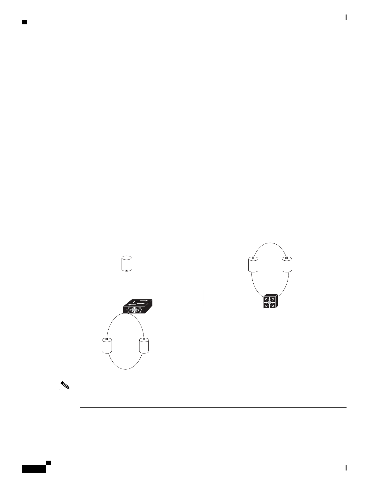
Interface Modes
Each physical Fibre Channel interface in a switch may operate in one of several port modes: E port, F
port, FL port, TL port, TE port, SD port, ST port, and B port (see
interface may be configured in auto or Fx port modes. These two modes determine the port type during
interface initialization.
Chapter 2 Configuring Interfaces
Figure 2-1). Besides these modes, each
Figure 2-1 Cisco MDS 9000 Family Switch Port Modes
NL port NL port
p
N port
ISL link
F port
FL port
Public
loop
NL port NL port
Note Interfaces are created in VSAN 1 by default. See the Cisco MDS 9000 Family NX-OS Fabric
E port E port
Private
loop
TL port
79528
Configuration Guide.
2-2
Each interface has an associated administrative configuration and an operational status:
• The administrative configuration does not change unless you modify it. This configuration has
various attributes that you can configure in administrative mode.
Cisco MDS 9000 Family NX-OS Interfaces Configuration Guide
OL-29284-01, Release 6.x
Page 25

Chapter 2 Configuring Interfaces
• The operational status represents the current status of a specified attribute like the interface speed.
Note When a module is removed and replaced with the same type of module, the configuration is retained. If
a different type of module is inserted, then the original configuration is no longer retained.
Each interface is briefly described in the sections that follow.
E Port
In expansion port (E port) mode, an interface functions as a fabric expansion port. This port may be
connected to another E port to create an Inter-Switch Link (ISL) between two switches. E ports carry
frames between switches for configuration and fabric management. They serve as a conduit between
switches for frames destined to remote N ports and NL ports. E ports support class 2, class 3, and class
F service.
An E port connected to another switch may also be configured to form a PortChannel (see Chapter 6,
“Configuring PortChannels”).
Information About Interfaces
This status cannot be changed and is read-only. Some values may not be valid when the interface is
down (for example, the operational speed).
F Port
FL Port
NP Ports
Note We recommend that you configure E ports on 16-port modules. If you must configure an E port on a
32-port oversubscribed module, then you can only use the first port in a group of four ports (for example,
ports 1 through 4, 5 through 8, and so forth). The other three ports cannot be used.
In fabric port (F port) mode, an interface functions as a fabric port. This port may be connected to a
peripheral device (host or disk) operating as an N port. An F port can be attached to only one N port. F
ports support class 2 and class 3 service.
In fabric loop port (FL port) mode, an interface functions as a fabric loop port. This port may be
connected to one or more NL ports (including FL ports in other switches) to form a public arbitrated
loop. If more than one FL port is detected on the arbitrated loop during initialization, only one FL port
becomes operational and the other FL ports enter nonparticipating mode. FL ports support class 2 and
class 3 service.
Note FL port mode is not supported on 4-port 10-Gbps switching module interfaces.
OL-29284-01, Release 6.x
An NP port is a port on a device that is in NPV mode and connected to the core switch via an F port. NP
ports function like N ports except that in addition to providing N port operations, they also function as
proxies for multiple, physical N ports.
For more details about NP ports and NPV, see Chapter 7, “Configuring N Port Virtualization.”
Cisco MDS 9000 Family NX-OS Interfaces Configuration Guide
2-3
Page 26

Information About Interfaces
TL Port
Tip We recommend configuring devices attached to TL ports in zones that have up to 64 zone members.
Chapter 2 Configuring Interfaces
In translative loop port (TL port) mode, an interface functions as a translative loop port. It may be
connected to one or more private loop devices (NL ports). TL ports are specific to Cisco MDS 9000
Family switches and have similar properties as FL ports. TL ports enable communication between a
private loop device and one of the following devices:
• A device attached to any switch on the fabric
• A device on a public loop anywhere in the fabric
• A device on a different private loop anywhere in the fabric
• A device on the same private loop
TL ports support class 2 and class 3 services.
Private loop devices refer to legacy devices that reside on arbitrated loops. These devices are not aware
of a switch fabric because they only communicate with devices on the same physical loop (see the
“TL
Port ALPA Caches” section on page 2-14).
TE Port
TF Port
Note TL port mode is not supported on Generation 2 switching module interfaces.
In trunking E port (TE port) mode, an interface functions as a trunking expansion port. It may be
connected to another TE port to create an extended ISL (EISL) between two switches. TE ports are
specific to Cisco MDS 9000 Family switches. They expand the functionality of E ports to support the
following:
• VSAN trunking
• Transport quality of service (QoS) parameters
• Fibre Channel trace (fctrace) feature
In TE port mode, all frames are transmitted in EISL frame format, which contains VSAN information.
Interconnected switches use the VSAN ID to multiplex traffic from one or more VSANs across the same
physical link. This feature is referred to as trunking in the Cisco MDS 9000 Family switches (see
Chapter 5, “Configuring Trunking”). TE ports support class 2, class 3, and class F service.
In trunking F port (TF port) mode, an interface functions as a trunking expansion port. It may be
connected to another trunked N port (TN port) or trunked NP port (TNP port) to create a link between a
core switch and an NPV switch or an HBA to carry tagged frames. TF ports are specific to Cisco MDS
9000 Family switches. They expand the functionality of F ports to support VSAN trunking.
In TF port mode, all frames are transmitted in EISL frame format, which contains VSAN information.
Interconnected switches use the VSAN ID to multiplex traffic from one or more VSANs across the same
physical link. This feature is referred to as trunking in the Cisco MDS 9000 Family (see
“Configuring Trunking”). TF ports support class 2, class 3, and class F service.
Chapter 5,
2-4
Cisco MDS 9000 Family NX-OS Interfaces Configuration Guide
OL-29284-01, Release 6.x
Page 27

Chapter 2 Configuring Interfaces
TNP Port
In trunking NP port (TNP port) mode, an interface functions as a trunking expansion port. It may be
connected to a trunked F port (TF port) to create a link to a core NPIV switch from an NPV switch to
carry tagged frames.
SD Port
In SPAN destination port (SD port) mode, an interface functions as a switched port analyzer (SPAN).
The SPAN feature is specific to switches in the Cisco MDS 9000 Family. It monitors network traffic that
passes though a Fibre Channel interface. This monitoring is done using a standard Fibre Channel
analyzer (or a similar switch probe) that is attached to an SD port. SD ports do not receive frames, they
only transmit a copy of the source traffic. The SPAN feature is nonintrusive and does not affect switching
of network traffic for any SPAN source ports (see the Cisco MDS 9000 Family NX-OS System
Management Configuration Guide).
ST Port
In the SPAN tunnel port (ST port) mode, an interface functions as an entry point port in the source switch
for the RSPAN Fibre Channel tunnel. The ST port mode and the remote SPAN (RSPAN) feature are
specific to switches in the Cisco MDS 9000 Family. When configured in ST port mode, the interface
cannot be attached to any device, and thus cannot be used for normal Fibre Channel traffic (see the Cisco
MDS 9000 Family NX-OS System Management Configuration Guide).
Information About Interfaces
Fx Port
B Port
Auto Mode
Note ST port mode is not supported on the Cisco MDS 9124 Fabric Switch, the Cisco Fabric Switch for HP
c-Class BladeSystem, and the Cisco Fabric Switch for IBM BladeCenter.
Interfaces configured as Fx ports can operate in either F port or FL port mode. The Fx port mode is
determined during interface initialization depending on the attached N port or NL port. This
administrative configuration disallows interfaces to operate in any other mode—for example, preventing
an interface to connect to another switch.
While E ports typically interconnect Fibre Channel switches, some SAN extender devices, such as the
Cisco PA-FC-1G Fibre Channel port adapter, implement a bridge port (B port) model to connect
geographically dispersed fabrics. This model uses B ports as described in the T11 Standard FC-BB-2.
If an FCIP peer is a SAN extender device that only supports Fibre Channel B ports, you need to enable
the B port mode for the FCIP link. When a B port is enabled, the E port functionality is also enabled and
they coexist. If the B port is disabled, the E port functionality remains enabled (see the Cisco MDS 9000
Family NX-OS IP Services Configuration Guide).
OL-29284-01, Release 6.x
Interfaces configured in auto mode can operate in one of the following modes: F port, FL port, E port,
TE port, or TF port. The port mode is determined during interface initialization. For example, if the
interface is connected to a node (host or disk), it operates in F port or FL port mode depending on the N
Cisco MDS 9000 Family NX-OS Interfaces Configuration Guide
2-5
Page 28

Information About Interfaces
port or NL port mode. If the interface is attached to a third-party switch, it operates in E port mode. If
the interface is attached to another switch in the Cisco MDS 9000 Family, it may become operational in
TE port mode (see
TL ports and SD ports are not determined during initialization and are administratively configured.
Note Fibre Channel interfaces on Storage Services Modules (SSMs) cannot be configured in auto mode.
Interface States
The interface state depends on the administrative configuration of the interface and the dynamic state of
the physical link.
Administrative States
The administrative state refers to the administrative configuration of the interface as described in
Table 2-1.
Chapter 2 Configuring Interfaces
Chapter 5, “Configuring Trunking”).
Operational States
Reason Codes
Ta b l e 2-1 Administrative States
Administrative State Description
Up Interface is enabled.
Down Interface is disabled. If you administratively disable an interface by shutting
down that interface, the physical link layer state change is ignored.
The operational state indicates the current operational state of the interface as described in Tab le 2-2.
Ta b l e 2-2 Operational States
Operational State Description
Up Interface is transmitting or receiving traffic as desired. To be in this state, an
interface must be administratively up, the interface link layer state must be up, and
the interface initialization must be completed.
Down Interface cannot transmit or receive (data) traffic.
Trunking Interface is operational in TE or TF mode.
2-6
Reason codes are dependent on the operational state of the interface as described in Table 2-3.
Cisco MDS 9000 Family NX-OS Interfaces Configuration Guide
OL-29284-01, Release 6.x
Page 29

Chapter 2 Configuring Interfaces
Ta b l e 2-3 Reason Codes for Interface States
Information About Interfaces
Administrative
Configuration
Operational
Status
Reason Code
Up Up None.
Down Down Administratively down—If you administratively configure an interface
as down, you disable the interface. No traffic is received or transmitted.
Up Down See Tab le 2-4.
Note Only some of the reason codes are listed in Table 2-4.
If the administrative state is up and the operational state is down, the reason code differs based on the
nonoperational reason code as described in
Table 2-4.
OL-29284-01, Release 6.x
Cisco MDS 9000 Family NX-OS Interfaces Configuration Guide
2-7
Page 30

Information About Interfaces
Ta b l e 2-4 Reason Codes for Nonoperational States
Reason Code (long version) Description
Link failure or not connected The physical layer link is not operational. All
SFP not present The small form-factor pluggable (SFP) hardware is not
Initializing The physical layer link is operational and the protocol
Reconfigure fabric in progress The fabric is currently being reconfigured.
Offline The Cisco NX-OS software waits for the specified
Inactive The interface VSAN is deleted or is in a suspended
Hardware failure A hardware failure is detected.
Error disabled Error conditions require administrative attention.
Chapter 2 Configuring Interfaces
Applicable
Modes
plugged in.
initialization is in progress.
R_A_TOV time before retrying initialization.
state.
To make the interface operational, assign that port to a
configured and active VSAN.
Interfaces may be error-disabled for various reasons.
For example:
• Configuration failure.
• Incompatible buffer-to-buffer credit configuration.
To make the interface operational, you must first fix the
error conditions causing this state; and next,
administratively shut down or enable the interface.
FC redirect failure A port is isolated because a Fibre Channel redirect is
unable to program routes.
No port activation license
available
A port is not active because it does not have a port
license.
SDM failure A port is isolated because SDM is unable to program
routes.
2-8
Cisco MDS 9000 Family NX-OS Interfaces Configuration Guide
OL-29284-01, Release 6.x
Page 31

Chapter 2 Configuring Interfaces
Table 2-4 Reason Codes for Nonoperational States (continued)
Reason Code (long version) Description
Isolation due to ELP failure The port negotiation failed. Only E ports
Isolation due to ESC failure The port negotiation failed.
Isolation due to domain
overlap
Isolation due to domain ID
assignment failure
Isolation due to the other side
of the link E port isolated
Isolation due to invalid fabric
reconfiguration
Isolation due to domain
manager disabled
Isolation due to zone merge
failure
Isolation due to VSAN
mismatch
Nonparticipating FL ports cannot participate in loop operations. It may
PortChannel administratively
down
Suspended due to incompatible
speed
Suspended due to incompatible
mode
Suspended due to incompatible
remote switch WWN
Information About Interfaces
Applicable
Modes
and TE ports
The Fibre Channel domains (fcdomain) overlap.
The assigned domain ID is not valid.
The E port at the other end of the link is isolated.
The port is isolated due to fabric reconfiguration.
The fcdomain feature is disabled.
The zone merge operation failed.
The VSANs at both ends of an ISL are different.
Only FL
happen if more than one FL port exists in the same
loop, in which case all but one FL port in that loop
ports and TL
ports
automatically enters nonparticipating mode.
The interfaces belonging to the PortChannel are down. Only
PortChannel
The interfaces belonging to the PortChannel have
interfaces
incompatible speeds.
The interfaces belonging to the PortChannel have
incompatible modes.
An improper connection is detected. All interfaces in a
PortChannel must be connected to the same pair of
switches.
Graceful Shutdown
Interfaces on a port are shut down by default (unless you modified the initial configuration).
The Cisco NX-OS software implicitly performs a graceful shutdown in response to either of the
following actions for interfaces operating in the E port mode:
• If you shut down an interface.
• If a Cisco NX-OS software application executes a port shutdown as part of its function.
A graceful shutdown ensures that no frames are lost when the interface is shutting down. When a
shutdown is triggered either by you or the Cisco NX-OS software, the switches connected to the
shutdown link coordinate with each other to ensure that all frames in the ports are safely sent through
the link before shutting down. This enhancement reduces the chance of frame loss.
OL-29284-01, Release 6.x
Cisco MDS 9000 Family NX-OS Interfaces Configuration Guide
2-9
Page 32

Information About Interfaces
A graceful shutdown is not possible in the following situations:
• If you physically remove the port from the switch.
• If in-order delivery (IOD) is enabled (for information about IOD, refer to the Cisco MDS 9000
Family NX-OS Fabric Configuration Guide).
• If the Min_LS_interval interval is higher than 10 seconds. For information about FSPF global
configuration, refer to the Cisco MDS 9000 Family NX-OS Fabric Configuration Guide.
Note This feature is only triggered if both switches at either end of this E port interface are MDS switches and
are running Cisco SAN-OS Release 2.0(1b) or later, or MDS NX-OS Release 4.1(1a) or later.
Port Administrative Speeds
By default, the port administrative speed for an interface is automatically calculated by the switch.
For internal ports on the Cisco Fabric Switch for HP c_Class BladeSystem and Cisco Fabric Switch for
IBM BladeCenter, a port speed of 1 Gbps is not supported. Auto-negotiation is supported between 2
Gbps and 4 Gbps only. Also, if the BladeCenter is a T chassis, then port speeds are fixed at 2 Gbps and
auto-negotiation is not enabled.
Chapter 2 Configuring Interfaces
Autosensing
Autosensing speed is enabled on all 4-Gbps and 8-Gbps switching module interfaces by default. This
configuration enables the interfaces to operate at speeds of 1 Gbps, 2 Gbps, or 4 Gbps on the 4-Gbps
switching modules, and 8 Gbps on the 8-Gbps switching modules. When autosensing is enabled for an
interface operating in dedicated rate mode, 4 Gbps of bandwidth is reserved, even if the port negotiates
at an operating speed of 1 Gbps or 2 Gbps.
To avoid wasting unused bandwidth on 48-port and 24-port 4-Gbps and 8-Gbps Fibre Channel switching
modules, you can specify that only 2 Gbps of required bandwidth be reserved, not the default of 4 Gbps
or 8 Gbps. This feature shares the unused bandwidth within the port group provided that it does not
exceed the rate limit configuration for the port. You can also use this feature for shared rate ports that
are configured for autosensing.
Tip When migrating a host that supports up to 2-Gbps traffic (that is, not 4 Gbps with autosensing
capabilities) to the 4-Gbps switching modules, use autosensing with a maximum bandwidth of 2 Gbps.
When migrating a host that supports up to 4-Gbps traffic (that is, not 8 Gbps with autosensing
capabilities) to the 8-Gbps switching modules, use autosensing with a maximum bandwidth of 4 Gbps.
Frame Encapsulation
The switchport encap eisl command only applies to SD port interfaces. This command determines the
frame format for all frames transmitted by the interface in SD port mode. If the encapsulation is set to
EISL, all outgoing frames are transmitted in the EISL frame format, regardless of the SPAN sources.
2-10
The switchport encap eisl command is disabled by default. If you enable encapsulation, all outgoing
frames are encapsulated, and you will see a new line (Encapsulation is eisl) in the show interface
SD_port_interface command output. See the Cisco MDS 9000 Family NX-OS System Management
Configuration Guide.
Cisco MDS 9000 Family NX-OS Interfaces Configuration Guide
OL-29284-01, Release 6.x
Page 33

Chapter 2 Configuring Interfaces
You can set the frame format to EISL for all frames transmitted by the interface in SD port mode. If you
sent the frame encapsulation to EISL, all outgoing frames are transmitted in the EISL frame format,
regardless of the SPAN sources. See the Cisco MDS 9000 Family NX-OS System Management
Configuration Guide.
Beacon LEDs
Figure 2-2 displays the status, link, and speed LEDs in a 16-port switching module.
Information About Interfaces
Speed LEDs
Figure 2-2 Cisco MDS 9000 Family Switch Interface Modes
2
1 43
1 Status LED
2 1/2-Gbps Fibre Channel port group
1. See the Cisco MDS 9000 Family NX-OS Fundamentals Configuration Guide.
2. See the “Speed LEDs” section on page 2-11.
3. See the “Generation 1 Interface Configuration Guidelines” section on page 2-18.
4. Refer to the Cisco MDS 9000 Family hardware installation guide for your platform.
1
3 Link LEDs1 and speed LEDs
3
4 Asset tag
4
Each port has one link LED on the left and one speed LED on the right.
The speed LED displays the speed of the port interface:
77686
2
• Off—The interface attached to that port is functioning at 1000 Mbps.
• On (solid green)—The interface attached to that port is functioning at 2000 Mbps (for 2 Gbps
interfaces).
The speed LED also displays if the beacon mode is enabled or disabled:
• Off or solid green—Beacon mode is disabled.
• Flashing green—The beacon mode is enabled. The LED flashes at one-second intervals.
Note Generation 2, Generation 3, and Generation 4 modules and fabric switches do not have speed LEDs.
Bit Error Thresholds
The bit error rate threshold is used by the switch to detect an increased error rate before performance
degradation seriously affects traffic.
OL-29284-01, Release 6.x
Cisco MDS 9000 Family NX-OS Interfaces Configuration Guide
2-11
Page 34

Information About Interfaces
The bit errors can occur for the following reasons:
• Faulty or bad cable.
• Faulty or bad GBIC or SFP.
• GBIC or SFP is specified to operate at 1 Gbps but is used at 2 Gbps.
• GBIC or SFP is specified to operate at 2 Gbps but is used at 4 Gbps.
• Short haul cable is used for long haul or long haul cable is used for short haul.
• Momentary sync loss.
• Loose cable connection at one or both ends.
• Improper GBIC or SFP connection at one or both ends.
A bit error rate threshold is detected when 15 error bursts occur in a 5-minute period. By default, the
switch disables the interface when the threshold is reached. You can enter a shutdown and no shutdown
command sequence to re-enable the interface.
You can configure the switch to not disable an interface when the threshold is crossed. By default, the
threshold disables the interface.
Chapter 2 Configuring Interfaces
SFP Transmitter Types
The small form-factor pluggable (SFP) hardware transmitters are identified by their acronyms when
displayed.
The small form-factor pluggable (SFP) hardware transmitters are identified by their acronyms when
displayed in the show interface brief command. If the related SFP has a Cisco-assigned extended ID,
then the show interface and show interface brief commands display the ID instead of the transmitter
type. The show interface transceiver command and the show interface fc slot/port transceiver
command display both values for Cisco-supported SFPs.
command output (see the “Displaying Interface Information” section on page 2-42).
Ta b l e 2-5 SFP Transmitter Acronym Definitions
Definition Acronym
Standard transmitters defined in the GBIC specifications
short wave laser swl
long wave laser lwl
long wave laser cost reduced lwcr
electrical elec
Extended transmitters assigned to Cisco-supported SFPs
CWDM-1470 c1470
CWDM-1490 c1490
CWDM-1510 c1510
CWDM-1530 c1530
CWDM-1550 c1550
CWDM-1570 c1570
Table 2-5 defines the acronyms used for SFPs.
Tabl e 2-5 defines the acronyms used in the
2-12
Cisco MDS 9000 Family NX-OS Interfaces Configuration Guide
OL-29284-01, Release 6.x
Page 35

Chapter 2 Configuring Interfaces
Table 2-5 SFP Transmitter Acronym Definitions (continued)
Definition Acronym
Standard transmitters defined in the GBIC specifications
CWDM-1590 c1590
CWDM-1610 c1610
TL Ports
Private loop devices refer to legacy devices that reside on arbitrated loops. These devices are not aware
of a switch fabric because they only communicate with devices on the same physical loop. The legacy
devices are used in Fibre Channel networks, and devices outside the loop may need to communicate with
them. The communication functionality is provided through TL ports. See the
on page 2-2.
TL port mode is not supported on the following hardware:
• Generation 2 switching module interfaces
Information About Interfaces
“Interface Modes” section
• Cisco MDS 9124 Fabric Switch
• Cisco Fabric Switch for HP c-Class BladeSystem
• Cisco Fabric Switch for IBM BladeCenter
Table 2-6 lists the TL port translations supported in Cisco MDS 9000 Family switches.
Ta b l e 2-6 Supported TL Port Translations
Translation from Translation to Example
Private initiator Private target From I1 to T1 or vice versa
Private initiator Public target — N port From I1 to T2 or vice versa
Private initiator Public target — NL port From I4 to T3 or vice versa
Public initiator — N port Private target From I2 to T1 or vice versa
Public initiator — NL port Private target From I3 to T1 or vice versa
OL-29284-01, Release 6.x
Cisco MDS 9000 Family NX-OS Interfaces Configuration Guide
2-13
Page 36

Information About Interfaces
Figure 2-3 shows examples of TL port translation support.
Figure 2-3 TL Port Translation Support Examples
target (T1)
Private
NL port
Private
initiator (I4)
NL port
Private
loop
TL port
Public
target (T2)
N port
F port
Private
initiator (I1)
Private
TL port
FL port
Chapter 2 Configuring Interfaces
NL port
loop
Public
initiator (I2)
N port
F port
TL Port ALPA Caches
Although TL ports cannot be automatically configured, you can manually configure entries in arbitrated
loop physical address (ALPA) caches. Generally, ALPA cache entries are automatically populated when
an ALPA is assigned to a device. Each device is identified by its port world wide name (pWWN). When
a device is allocated an ALPA, an entry for that device is automatically created in the ALPA cache.
A cache contains entries for recently allocated ALPA values. These caches are maintained on various TL
ports. If a device already has an ALPA, the Cisco NX-OS software attempts to allocate the same ALPA
to the device each time. The ALPA cache is maintained in persistent storage and saves information across
switch reboots. The maximum cache size is 1000 entries. If the cache is full, and a new ALPA is
allocated, the Cisco NX-OS software discards an inactive cache entry (if available) to make space for
the new entry. See the
Public
target (3)
NL port
Public
loop
NL port
Public
initiator (I3)
91699
“TL Port” section on page 2-4 for more information on TL ports.
Port Guard
Cisco MDS 9000 Family NX-OS Interfaces Configuration Guide
2-14
The port guard feature is intended for use in environments where the system and application environment
does not adapt quickly and efficiently to a port going down and back up, or to a port rapidly cycling up
and down, which can happen in some failure modes. For example, if a system takes five seconds to
stabilize after a port goes down, but the port is going up and down once a second, a more severe failure
in the fabric might occur.
OL-29284-01, Release 6.x
Page 37

Chapter 2 Configuring Interfaces
The port guard feature gives the SAN administrator the ability to prevent this issue from occurring in
environments that are vulnerable to these problems. The port can be configured to stay down after the
first failure or after a specified number of failures in a specified time period. This allows the SAN
administrator to intervene and control the recovery, avoiding any problems caused by the cycling.
Using the port guard feature, you can restrict the number of error reports and bring a malfunctioning port
to down state dynamically. A port can be configured to go into error-disabled state for specific types of
failures.
A general link failure caused by link-down is the superset of all other causes. The sum of the number of
all other causes equals to the number of link-down link failures. This means a port is brought to down
state when it reaches the maximum number of allowed link failures or the number of specific causes.
The causes of link failure can be any of the following:
• ESP trustsec-violation
• Bit-errors
• Signal loss
• Sync loss
• Link reset
• Credit loss
• Additional causes might be the following:
Information About Interfaces
Port Monitor
–
Not operational (NOS).
–
Too many interrupts.
–
Cable is disconnected.
–
Hardware recoverable errors.
–
The connected device rebooted (F ports only).
–
The connected linecard rebooted (ISL only).
Port monitor helps to monitor the performance and the status of ports and generate alerts when problems
occur. You can configure the thresholds for various counters and trigger an event when the values cross
the threshold settings.
The default port monitor policy has the following threshold values:
Counter
Threshold
Ty pe
Interval
(Seconds)
% Rising
Threshold
Event
% Falling
Threshold
Event
Link Loss Delta 60 5 4 1 4
Sync Loss Delta 60 5 4 1 4
Protocol Error Delta 60 1 4 0 4
Signal Loss Delta 60 5 4 1 4
Invalid Words Delta 60 1 4 0 4
Invalid CRCs Delta 60 5 4 1 4
OL-29284-01, Release 6.x
Cisco MDS 9000 Family NX-OS Interfaces Configuration Guide
2-15
Page 38

Information About Interfaces
Chapter 2 Configuring Interfaces
Counter
RX Performance Delta 60 2147483648 4 524288000 4
TX Performance Delta 60 2147483648 4 524288000 4
Port Monitor Port Guard
Port monitor port guard is a feature that disables or shuts down a port when an event occurs. Depending
on the configuration, when an event occurs the port is either error-disabled or flapped.
Port monitor port guard is a different or separate feature that functions based on the configuration of the
errordisable command.
Port Group Monitor
Each line card or module has a predefined set of ports which share the same backplane bandwidth called
port groups. While oversubscription is a feature, the port group monitor feature helps to monitor the
spine bandwidth utilization. An alarm syslog is generated so that you can provision the ports across port
groups evenly to manage the oversubscription better.
When the port group monitor feature is enabled and a policy consisting of polling interval in seconds,
and the raising and falling thresholds in percentage are specified, port group monitor generates a syslog
if a port group traffic goes above the specified percentage of the maximum supported bandwidth for that
port group (for rx and for tx) and another syslog if the value falls below the specified threshold.
The default port group policy has the following threshold values:
Threshold
Ty pe
Interval
(Seconds)
% Rising
Threshold Event
% Falling
Threshold Event
Counter Threshold Type Interval (Seconds) % Rising Threshold % Falling Threshold
RX Performance Delta 60 80 20
TX Performance Delta 60 80 20
Local Switching
Local switching can be enabled in Generation 4 modules, which allows traffic to be switched directly
with a local crossbar when the traffic is directed from one port to another on the same line card. By using
local switching, an extra switching step is avoided, which decreases the latency.
When using local switching, note the following guidelines:
• All ports need to be in shared mode, which usually is the default state. To place a port in shared
• E ports are not allowed in the module because they must be in dedicated mode.
Note Local Switching is not supported on MDS 9710.
mode, enter the switchport ratemode shared command.
2-16
Cisco MDS 9000 Family NX-OS Interfaces Configuration Guide
OL-29284-01, Release 6.x
Page 39

Chapter 2 Configuring Interfaces
Slow Drain Device Detection and Congestion Avoidance
All data traffic between end devices in a SAN fabric is carried by Fibre Channel Class 3. In some cases,
the traffic is carried by Class 2 services that use link-level, per-hop-based, and buffer-to-buffer flow
control. These classes of service do not support end-to-end flow control. When there are slow devices
attached to the fabric, the end devices do not accept the frames at the configured or negotiated rate. The
slow devices lead to ISL credit shortage in the traffic destined for these devices and they congest the
links. The credit shortage affects the unrelated flows in the fabric that use the same ISL link even though
destination devices do not experience slow drain.
This feature provides various enhancements to detect slow drain devices that are causing congestion in
the network and also provides a congestion avoidance function.
This feature is focused mainly on the edge ports that are connected to slow drain devices. The goal is to
avoid or minimize the frames being stuck in the edge ports due to slow drain devices that are causing
ISL blockage. To avoid or minimize the stuck condition, configure lesser frame timeout for the ports.
No-credit timeout drops all packets once the slow drain is detected using the configured thresholds. The
lesser frame timeout value helps to alleviate the slow drain condition that affects the fabric by dropping
the packets on the edge ports sooner than the time they actually get timed out (500 ms). This function
frees the buffer space in ISL, which can be used by other unrelated flows that do not experience slow
drain condition.
Information About Interfaces
Note This feature is used mainly for edge ports that are connected to slow edge devices. Even though this
feature can be applied to ISLs as well, we recommend that you apply this feature only for edge F ports
and retain the default configuration for ISLs as E and TE ports. This feature is not supported on
Generation 1 modules.
Management Interfaces
You can remotely configure the switch through the management interface (mgmt0). To configure a
connection on the mgmt0 interface, you must configure either the IP version 4 (IPv4) parameters (IP
address, subnet mask, and default gateway) or the IP version 6 (IPv6) parameters so that the switch is
reachable.
Before you begin to configure the management interface manually, obtain the switch’s IPv4 address and
subnet mask, or the IPv6 address.
The management port (mgmt0) is autosensing and operates in full-duplex mode at a speed of
10/100/1000 Mbps. Autosensing supports both the speed and the duplex mode. On a Supervisor-1
module, the default speed is 100 Mbps and the default duplex mode is auto. On a Supervisor-2 module,
the default speed is auto and the default duplex mode is auto.
Note You need to explicitly configure a default gateway to connect to the switch and send IP packets or add a
route for each subnet.
OL-29284-01, Release 6.x
Cisco MDS 9000 Family NX-OS Interfaces Configuration Guide
2-17
Page 40

Prerequisites for Interfaces
VSAN Interfaces
VSANs apply to Fibre Channel fabrics and enable you to configure multiple isolated SAN topologies
within the same physical infrastructure. You can create an IP interface on top of a VSAN and then use
this interface to send frames to this VSAN. To use this feature, you must configure the IP address for
this VSAN. VSAN interfaces cannot be created for nonexisting VSANs.
Prerequisites for Interfaces
Before you begin configuring the interfaces, ensure that the modules in the chassis are functioning as
designed. To verify the status of a module at any time, enter the show module command in EXEC mode.
For information about verifying the module status, refer to the Cisco NX-OS Fundamentals
Configuration Guide.
Guidelines and Limitations
Chapter 2 Configuring Interfaces
This section includes the following topics:
• Generation 1 Interface Configuration Guidelines, page 2-18
• Private Loop Configuration Guidelines, page 2-19
• VSAN Interface Configuration Guidelines, page 2-19
Generation 1 Interface Configuration Guidelines
The Generation 1 interfaces configuration guidelines apply to the following hardware:
• The 32-port, 2-Gbps or 1-Gbps switching module interfaces
• The Cisco MDS 9140 and 9120 switch interfaces
Note Due to the hardware design of the MDS 9134 switch, we do not support interface
out-of-service action on either of its two 10-Gigabit ports. This is because no internal port
hardware resource is released when an out-of-service action is performed on these
10-Gigabit ports.
When configuring these host-optimized ports, the following port mode guidelines apply:
• You can configure only the first port in each 4-port group (for example, the first port in ports 1-4,
the fifth port in ports 5-8, and so on) as an E port. If the first port in the group is configured as an E
port, the other three ports in each group (ports 2-4, 6-8, and so on) are not usable and remain
shutdown.
• If you execute the write erase command on a 32-port switching module, and then copy a saved
configuration to the switch from a text file that contains the no system default switchport
shutdown command, you need to copy the text file to the switch again for the E ports to come up
without manual configuration.
2-18
• If any of the other three ports are enabled, you cannot configure the first port as an E port. The other
three ports continue to remain enabled.
Cisco MDS 9000 Family NX-OS Interfaces Configuration Guide
OL-29284-01, Release 6.x
Page 41

Chapter 2 Configuring Interfaces
• The auto mode is not allowed in a 32-port switching module or the host-optimized ports in the Cisco
9100 Series (16 host-optimized ports in the Cisco MDS 9120 switch and 32 host-optimized ports in
the Cisco MDS 9140 switch).
• The default port mode is Fx (Fx negotiates to F or FL) for 32-port switching modules.
• The 32-port switching module does not support FICON.
Note We recommend that you configure your E ports on a 16-port switching module. If you must configure
an E port on a 32-port host-optimized switching module, the other three ports in that 4-port group cannot
be used.
Note In the Cisco MDS 9100 Series, the groups of ports that are located on the left and outlined in white are
full line rate. The other ports are host-optimized. Each group of 4 host-optimized ports have the same
features as for the 32-port switching module.
Private Loop Configuration Guidelines
Guidelines and Limitations
Follow these guidelines when configuring private loops:
• A maximum of 64 fabric devices can be proxy to a private loop.
• Fabric devices must be in the same zone as private loop devices to be proxy to the private loop.
• Each private device on a TL port may be included in a different zone.
• All devices on the loop are treated as private loops. You cannot mix private and public devices on
the loop if the configured port mode is TL.
• The only FC4-type supported by TL ports is SCSI (FCP).
• Communication between a private initiator to a private target on the same private loop does not
invoke TL port services.
VSAN Interface Configuration Guidelines
Follow these guidelines when creating or deleting VSAN interfaces:
• Create a VSAN before creating the interface for that VSAN. If a VSAN does not exist, the interface
cannot be created.
• Create the interface VSAN—it is not created automatically.
• If you delete the VSAN, the attached interface is automatically deleted.
• Configure each interface only in one VSAN.
Tip After configuring the VSAN interface, you can configure an IP address or Virtual Router Redundancy
OL-29284-01, Release 6.x
Protocol (VRRP) feature. See the Cisco MDS 9000 Family NX-OS IP Services Configuration Guide.
Cisco MDS 9000 Family NX-OS Interfaces Configuration Guide
2-19
Page 42

Default Settings
Default Settings
Table 2-7 lists the default settings for interface parameters.
Ta b l e 2-7 Default Interface Parameters
Parameters Default
Interface mode Auto
Interface speed Auto
Administrative state Shutdown (unless changed during initial setup)
Trunk mode On (unless changed during initial setup) on
Trunk-allowed VSANs or VF-IDs 1 to 4093
Interface VSAN Default VSAN (1)
Beacon mode Off (disabled)
EISL encapsulation Disabled
Data field size 2112 bytes
Chapter 2 Configuring Interfaces
non-NPV and NPIV core switches. Off on NPV
switches.
Configuring Interfaces
This section includes the following topics:
• Configuring Fibre Channel Interfaces, page 2-21
• Setting the Interface Administrative State, page 2-22
• Configuring Interface Modes, page 2-22
• Configuring System Default Port Mode F, page 2-23
• Configuring Port Administrative Speeds, page 2-25
• Configuring Port Speed Group, page 2-26
• Configuring the Interface Description, page 2-26
• Specifying a Port Owner, page 2-27
• Configuring Beacon Mode, page 2-27
• Disabling Bit Error Threshold, page 2-28
• Configuring Switch Port Attribute Default Values, page 2-28
• Configuring TL Ports, page 2-29
• Manually Inserting Entries into the ALPA Cache, page 2-29
• Clearing the ALPA Cache, page 2-29
• Configuring Port Guard, page 2-30
• Configuring Port Monitor, page 2-31
• Configuring Port Group Monitor, page 2-34
2-20
Cisco MDS 9000 Family NX-OS Interfaces Configuration Guide
OL-29284-01, Release 6.x
Page 43

Chapter 2 Configuring Interfaces
• Configuring Management Interfaces, page 2-37
• Creating VSAN Interfaces, page 2-38
• Configuring Slow Drain Device Detection and Congestion Avoidance, page 2-38
For more information on configuring mgmt0 interfaces, refer to the Cisco MDS 9000 Family NX-OS
Fundamentals Configuration Guide and Cisco MDS 9000 Family NX-OS IP Services Configuration
Guide.
For more information on configuring Gigabit Ethernet interfaces, see the Cisco MDS 9000 Family
NX-OS IP Services Configuration Guide.
Configuring Fibre Channel Interfaces
Detailed Steps
To configure a Fibre Channel interface, follow these steps:
Command Purpose
Step 1
Step 2
switch# config t
switch(config)# interface fc1/1
switch(config-if)#
Configuring Interfaces
Enters configuration mode.
Selects a Fibre Channel interface and enters interface
configuration submode.
Step 1
Step 2
Note When a Fibre Channel interface is configured, it is
automatically assigned a unique world wide name
(WWN). If the interface’s operational state is up, it is
also assigned a Fibre Channel ID (FC ID).
To configure a range of interfaces, follow these steps:
Command Purpose
switch# config t
switch(config)# interface fc1/1 - 4 , fc2/1 - 3
switch(config-if)#
Enters configuration mode.
Selects the range of Fibre Channel interfaces
and enters interface configuration submode3.
Note In this command, provide a space
before and after the comma.
For the Cisco Fabric Switch for HP c-Class BladeSystem and the Cisco Fabric Switch for IBM
BladeCenter, you can configure a range of interfaces among internal ports or external ports, but you
cannot mix both interface types within the same range. For example, “bay 1-10, bay 12” or “ext 0, ext
15-18” are valid ranges, but “bay 1-5, ext 15-17” is not.
OL-29284-01, Release 6.x
Cisco MDS 9000 Family NX-OS Interfaces Configuration Guide
2-21
Page 44

Configuring Interfaces
Setting the Interface Administrative State
Detailed Steps
To gracefully shut down an interface, follow these steps:
Command Purpose
Step 1
Step 2
Step 3
Step 1
Step 2
Step 3
switch# config t
switch(config)# interface fc1/1
switch(config-if)# shutdown
To enable traffic flow, follow these steps:
Command Purpose
switch# config t
switch(config)# interface fc1/1
switch(config-if)# no shutdown
Chapter 2 Configuring Interfaces
Enters configuration mode.
Selects a Fibre Channel interface and enters interface
configuration submode.
Gracefully shuts down the interface and administratively
disables traffic flow (default).
Enters configuration mode.
Selects a Fibre Channel interface and enters interface
configuration submode.
Enables traffic flow to administratively allow traffic when
the no prefix is used (provided the operational state is up).
Configuring Interface Modes
Detailed Steps
To configure the interface mode, follow these steps:
Command Purpose
Step 1
Step 2
Step 3
switch# config t
switch(config)# interface fc1/1
switch(config-if)#
switch(config-if)# switchport mode F
switch(config-if)#
switch(config-if)# switchport mode auto
switch(config-if)#
Enters configuration mode.
Selects a Fibre Channel interface and enters interface
configuration submode.
Configures the administrative mode of the port. You
can set the operational state to auto, E, F, FL, Fx, TL,
NP, or SD port mode.
Note Fx ports refers to an F port or an FL port (host
connection only), but not E ports.
Configures the interface mode to auto-negotiate an E,
F, FL, or TE port mode (not TL or SD port modes) of
operation.
Note TL ports and SD ports cannot be configured
automatically. They must be administratively
configured.
Note You cannot configure Fibre Channel interfaces
on SSMs in auto mode.
2-22
Cisco MDS 9000 Family NX-OS Interfaces Configuration Guide
OL-29284-01, Release 6.x
Page 45

Chapter 2 Configuring Interfaces
Configuring System Default Port Mode F
The system default switchport mode F command sets the administrative mode of all Fibre Channel
ports to mode F, while avoiding traffic disruption caused by the formation of unwanted Inter-Switch
Links (ISLs). This command is part of the setup utility that runs during bootup after a write erase or
reload. It can also be executed from the command line in configuration mode. This command changes
the configuration of the following ports to administrative mode F:
• All ports that are down and that are not out-of-service.
• All F ports that are up, whose operational mode is F, and whose administrative mode is not F.
This command does not affect the configuration of the following ports:
• All user-configured ports, even if they are down.
• All non-F ports that are up; however, if non-F ports are down, this command changes the
administrative mode of those ports.
Restrictions
• To ensure that ports that are part of ISLs do not get changed to port mode F, configure the ports in
port mode E, rather than in Auto mode.
• When the command is executed from the command line, switch operation remains graceful. No ports
are flapped.
Configuring Interfaces
Detailed Steps
To set the administrative mode of Fibre Channel ports to mode F in the CLI, follow these steps:
Command Purpose
Step 1
Step 2
Note For detailed information about the switch setup utility, see the Cisco MDS 9000 Family NX-OS
switch# config t
switch(config)# system default
switchport mode F
switch(config)# no system default
switchport mode F
Enters configuration mode.
Sets the administrative mode of Fibre Channel ports to
mode F (if applicable).
Sets the administrative mode of Fibre Channel ports to
the default (unless user configured).
Fundamentals Configuration Guide.
Example 2-1 shows the command in the setup utility, and Example 2-2 shows the command from the
command line.
Example 2-1 Setup Utility
Configure default switchport mode F (yes/no) [n]: y
Example 2-2 Command Line
OL-29284-01, Release 6.x
switch(config)# system default switchport mode F
Cisco MDS 9000 Family NX-OS Interfaces Configuration Guide
2-23
Page 46

Configuring Interfaces
Configuring ISL between Two Switches
Note Ensure the FC cable is connected between the ports and do a no-shut on each port.
E-port mode is used when the port functions as one end of an Inter-Switch Link (ISL) setting. When you
set the port mode to E, you restrict the port coming up as an E port (trunking or non-trunking, depending
on the trunking port mode).
switch# conf t --------> Enter configuration commands, one per line. End with CNTL/Z.
switch(config)# interface fc <Slot No/Port No>
switch(config-if)# switchport mode E
switch(config-if)# end
Ensure you follow this on both the switches between which you are attempting to bring up the ISL link.
Configuring 10-Gbps FC Mode
The 48-port 8-Gbps Advanced Fibre Channel module (DS-X9248-256K9) and the 32-port 8-Gbps
Advanced Fibre Channel module (DS-X9232-256K9)can switch between two speed modes—the 1-, 2-,
4-, 8-Gbps or 10-Gbps. By default, the modules are online in the 1-, 2-, 4-, and 8-Gbps modes when they
are loaded for the first time. There are two ways to change the ports to the 10-Gbps speed mode:
Chapter 2 Configuring Interfaces
• Using the 10G-speed mode command, which is the recommended method.
• Using the generic speed configuration switchport speed command which has certain constraints.
The following conditions apply when the ports in the module can be configured to 10-Gbps speed mode:
• The ports in the module can be configured to 10-Gbps speed only when the DS-13SLT-FAB3 module
bandwidth is 256-G. Any other combination of fabric modules will not let the ports come up in
10-Gbps.
• When in 10-Gbps mode, the ports in the module that are not 10-Gbps capable are disabled and will
be in out-of-service state.
• The ports function only in full rate mode. They cannot be moved to shared rate mode.
• The ports cannot be configured in any other speed.
• Ports that are capable of 10-Gbps that are disabled or out-of-service cannot be put back in service
using the no out-of-service command. To put these ports back in service, all ports in the module
first have to be moved to the out-of-service state. Then they can be brought back to the in service
state.
• Local switching must be disabled, otherwise, ports cannot be configured in dedicated mode.
Only certain ports on the 48-port and 32-port 8-Gbps Advanced Fibre Channel modules are 10-Gbps
capable. When running in 10-Gbps mode, the non-10-Gbps ports cannot be operational. They have to be
either in shut state or out-of-service state.
2-24
Cisco MDS 9000 Family NX-OS Interfaces Configuration Guide
OL-29284-01, Release 6.x
Page 47

Chapter 2 Configuring Interfaces
Detailed Steps
To configure the interface mode, follow these steps:
Command Purpose
Step 1
Step 2
Step 3
switch# config t
switch(config)# interface fc1/1-12
switch(config-if)#
switch(config-if)# 10G-speed-mode
Configuring Interfaces
Enters configuration mode.
Selects a Fibre Channel interface and enters interface
configuration submode.
Note Ensure that one full ASIC range of ports are
selected before executing this command. For
example, /1-12 for a 48-port module or
fcY/1-8 for a 32-port module.
The first ASIC on the 48-port module has ports
fc1/1-12.
Configures all the ports (fc1 to 12) to out-of-service
state.
Moves the ports that are capable of a10-Gbps
configuration (fc1/4-8 and fc1/10) to in-service state.
Sets the speed on ports fc1/4-8 and fc1/10 to 10-Gbps.
Sets port modes on these ports to dedicated.
switch(config-if)# no 10G-speed-mode
Configuring Port Administrative Speeds
Restrictions
• Changing the port administrative speed is a disruptive operation.
Detailed Steps
To configure the port speed of the interface, follow these steps:
Command Purpose
Step 1
Step 2
switch# config t
switch(config)# interface fc 1/1
Performs a no shut on these ports.
Reverts the settings and puts all the ports (fc1 to 12) in
out-of-service state and moves them to in-service
state.
Enters configuration mode.
Selects the fc interface and enters interface
configuration mode.
OL-29284-01, Release 6.x
Cisco MDS 9000 Family NX-OS Interfaces Configuration Guide
2-25
Page 48

Configuring Interfaces
Command Purpose
Step 3
switch(config-if)# switchport speed 1000
switch(config-if)# switchport speed
10000
switch(config-if)# no switchport speed
Configuring Port Speed Group
Chapter 2 Configuring Interfaces
Configures the port speed of the interface to 1000
Mbps.
The number indicates the speed in megabits per
second (Mbps).
Configures the port speed of the interface to 10000
Mbps (for 10-Gbps).
Note All the 10-Gbps capable interfaces, except the
interface that is being configured, must be in
the out-of-service state. At least one other
10-Gbps capable interface must be in the
in-service state.
Reverts the factory default (auto) administrative speed
of the interface.
Detailed Steps
To configure the port speed group of the interface, follow these steps:
Command Purpose
Step 1
Step 2
Step 3
switch# config t
switch(config)# interface fc 1/1
switch(config-if)# speed group 10g
switch(config-if)# no speed group 10g
Configuring the Interface Description
The interface description can be any alphanumeric string.
Detailed Steps
To configure a description for an interface, follow these steps:
Enters configuration mode.
Selects the fc interface and enters interface
configuration mode.
Configures the port speed group to 10 Gbps.
Note The preferred way of changing the speed
group is the 10g-speed-mode command.
Unsets the port speed group and reverts to the factory
default (auto) administrative speed group of the
interface.
2-26
Command Purpose
Step 1
Step 2
Cisco MDS 9000 Family NX-OS Interfaces Configuration Guide
switch# config t
switch(config)# interface fc1/1
switch(config-if)#
Enters configuration mode.
Selects a Fibre Channel interface and
enters interface configuration submode.
OL-29284-01, Release 6.x
Page 49

Chapter 2 Configuring Interfaces
Command Purpose
Step 3
switch(config-if)# switchport description cisco-HBA2
switch(config-if)# no switchport description
Specifying a Port Owner
Using the port owner feature, you can specify the owner of a port and the purpose for which a port is
used so that the other administrators are informed.
Note The port guard and port owner features are available for all ports regardless of the operational mode.
Detailed Steps
To specify or remove the port owner, follow these steps:
Configuring Interfaces
Configures the description of the
interface. The string can be up to 80
characters long.
Clears the description of the interface.
Command Purpose
Step 1
Step 2
Step 3
switch# config t
switch(config)# interface fc1/1
switch(config)# switchport owner
switch(config)# no switchport owner
To display the owner description specified for a port, use the following commands:
switch# show running interface fc
switch# show port internal info interface fc
Configuring Beacon Mode
By default, the beacon mode is disabled on all switches. The beacon mode is indicated by a flashing
green light that helps you identify the physical location of the specified interface. Configuring the
beacon mode has no effect on the operation of the interface.
Detailed Steps
Enters configuration mode.
Selects the port interface.
description
Specifies the owner of the switch port. The
description can include name of the owner and
the purpose for which the port is used. The
description can be up to 80 characters long.
Removes (default) the port owner description.
module-number/interface-number
module-number/interface-number
Step 1
Step 2
OL-29284-01, Release 6.x
To enable beacon mode for a specified interface or range of interfaces, follow these steps:
Command Purpose
switch# config t
switch(config)#
switch(config)# interface fc1/1
switch(config-if)#
Cisco MDS 9000 Family NX-OS Interfaces Configuration Guide
Enters configuration mode.
Selects a Fibre Channel interface and enters
interface configuration submode.
2-27
Page 50

Configuring Interfaces
Command Purpose
Step 3
switch(config-if)# switchport beacon
switch(config-if)# no switchport beacon
Troubleshooting Tips
• The flashing green light turns on automatically when an external loopback is detected that causes
the interfaces to be isolated. The flashing green light overrides the beacon mode configuration. The
state of the LED is restored to reflect the beacon mode configuration after the external loopback is
removed.
Disabling Bit Error Threshold
Detailed Steps
To disable the bit error threshold for an interface, follow these steps:
Chapter 2 Configuring Interfaces
Enables the beacon mode for the interface.
Disables the beacon mode for the interface.
Command Purpose
Step 1
Step 2
Step 3
switch# config t
switch(config)# interface fc1/1
switch(config-if)#
switch(config-if)# switchport ignore
bit-errors
switch(config-if)# no switchport ignore
bit-errors
Troubleshooting Tips
• Regardless of the setting of the switchport ignore bit-errors command, the switch generates a
syslog message when bit-error threshold events are detected.
Configuring Switch Port Attribute Default Values
You can configure attribute default values for various switch port attributes. These attributes will be
applied globally to all future switch port configurations, even if you do not individually specify them at
that time.
Enters configuration mode.
Selects a Fibre Channel interface and enters
interface configuration submode.
Prevents the detection of bit error threshold
events from disabling the interface.
Prevents the detection of bit error threshold
events from enabling the interface.
2-28
Cisco MDS 9000 Family NX-OS Interfaces Configuration Guide
OL-29284-01, Release 6.x
Page 51

Chapter 2 Configuring Interfaces
Detailed Steps
To configure switch port attributes, follow these steps:
Command Purpose
Step 1
Step 2
switch# config t
switch(config)# no system default
switchport shutdown
switch(config)#
switch(config)# system default
switchport shutdown
switch(config)#
switch(config)# system default
switchport trunk mode auto
switch(config)#
Configuring Interfaces
Enters configuration mode.
Configures the default setting for administrative state of an
interface as Up. (The factory default setting is Down).
Tip This command is applicable only to interfaces for
which no user configuration exists for the
administrative state.
Configures the default setting for administrative state of an
interface as Down. This is the factory default setting.
Tip This command is applicable only to interfaces for
which no user configuration exists for the
administrative state.
Configures the default setting for administrative trunk mode
state of an interface as Auto.
Note The default setting is trunk mode on.
Configuring TL Ports
Private loops require setting the interface mode to TL.
Use the switchport mode command to configure a TL port. See the “Configuring Interface Modes”
section on page 2-22.
Manually Inserting Entries into the ALPA Cache
Detailed Steps
To manually insert entries into the ALPA cache, follow these steps:
Command Purpose
Step 1
Step 2
Step 3
switch# config t
switch(config)# tlport alpa-cache interface
fc1/2 pwwn 22:00:00:20:37:46:09:bd alpa 0x02
switch(config)# tlport alpa-cache interface
fc1/3 pwwn 22:00:00:20:37:46:09:bd
Clearing the ALPA Cache
Enters configuration mode.
Configures manual entries into the ALPA cache.
Removes this entry from the ALPA cache.
OL-29284-01, Release 6.x
The clear tlport alpa-cache command clears the entire content of the ALPA cache.
Cisco MDS 9000 Family NX-OS Interfaces Configuration Guide
2-29
Page 52

Configuring Interfaces
Configuring Port Guard
Detailed Steps
To enable or disable the port guard for a port, follow these steps:
Command Purpose
Step 1
Step 2
Step 3
Step 4
switch# config t
switch(config)# interface fc1/1
switch(config)# errdisable detect cause
link-down
switch(config)# errdisable detect cause
link-down [num-times
seconds
switch(config)# no errdisable detect cause
link-down
switch(config)# errdisable detect cause
{trustsec-violation | bit-errors |
credit-loss | link-reset | signal-loss |
sync-loss}
switch(config)# errdisable detect cause
{trustsec-violation | bit-errors |
credit-loss | link-reset | signal-loss |
sync-loss} [num-times
seconds
switch(config)# no errdisable detect cause
{trustsec-violation | bit-errors |
credit-loss | link-reset | signal-loss |
sync-loss}
]
]
number
number
duration
duration
Chapter 2 Configuring Interfaces
Enters configuration mode.
Selects the port interface.
Brings the port to down state if the link flaps
once.
Enables the port guard configuration for the
interface. Brings the port to down state if the link
flaps for the number of instances within the
specified seconds.
Removes (default) the port guard configuration
for the interface. The link resumes flapping and
sending error reports normally.
Brings the port to down state if the specified error
occurs even once.
Brings the port to down state if the specified error
occurs for the number of instances within the
specified seconds.
Removes (default) the port guard configuration
for the interface. The link resumes flapping and
sending error reports normally.
Examples
2-30
This example shows how to configure port guard to bring a port to down state if the link flaps 5 times
within 120 seconds based on multiple causes:
Switch# config t
Switch (config)# interface fc1/1
Switch (config-if)# errdisable detect cause link-down num-times 5 duration 120
Switch (config-if)# errdisable detect cause bit-errors num-times 5 duration 120
Switch (config-if)# errdisable detect cause credit-loss num-times 5 duration 120
The above example sets the configuration to the following status:
• The port will be error-disabled due to bit errors if the port suffers link failure due to bit errors 5 times
in 120 seconds.
• The port will be error-disabled due to credit loss if the port suffers link failure due to credit loss 5
times in 120 seconds.
• The port will be error-disabled due to link down if the port suffers link failure due to bit errors 2
times and link-failure due to credit loss 3 times in 120 seconds.
This example shows the internal information about a port in down state because of TrustSec violation:
Cisco MDS 9000 Family NX-OS Interfaces Configuration Guide
OL-29284-01, Release 6.x
Page 53

Chapter 2 Configuring Interfaces
Switch# show port internal info interface fc8/3
fc8/3 is down (Error disabled - port down due to trustsec violation)
Hardware is Fibre Channel, SFP is short wave laser w/o OFC (SN)
Port WWN is 21:c3:00:0d:ec:10:57:80
Admin port mode is E, trunk mode is on
snmp link state traps are enabled
Port vsan is 1
Receive data field Size is 2112
Beacon is turned off
5 minutes input rate 0 bits/sec, 0 bytes/sec, 0 frames/sec
5 minutes output rate 0 bits/sec, 0 bytes/sec, 0 frames/sec
11274 frames input, 1050732 bytes
0 discards, 0 errors
0 CRC, 0 unknown class
0 too long, 0 too short
11242 frames output, 971900 bytes
0 discards, 0 errors
11 input OLS, 34 LRR, 10 NOS, 0 loop inits
72 output OLS, 37 LRR, 2 NOS, 0 loop inits
Interface last changed at Sun Nov 27 07:34:05 1988
admin port-down trustsec-violation(3) num_times 0, duration = 0
state reason (Error disabled - port down due to trustsec violation)
Port guard trustsec violation is Enabled
errdisabled on trustsec violation TRUE, oper cnt = 1
port guard first trustsec violation Sun Nov 27 07:34:05 1988
Configuring Interfaces
Troubleshooting Tips
• Link down is the superset of all other causes. A port is brought to down state if the total number of
other causes equals to the number of allowed link-down failures.
• Even if the link does not flap due to failure of the link, and port guard is not enabled, the port goes
into a down state if too many invalid FLOGI requests are received from the same host. Use the shut
and the no shut commands consecutively to bring up the link.
Configuring Port Monitor
This section includes the following topics:
• Enabling Port Monitor, page 2-31
• Configuring a Port Monitor Policy, page 2-32
• Activating a Port Monitor Policy, page 2-34
Enabling Port Monitor
Detailed Steps
To enable port monitor, follow these steps:
Step 1
Step 2
OL-29284-01, Release 6.x
Command Purpose
switch# config t
switch(config)# port-monitor enable
switch(config)# no port-monitor enable
Cisco MDS 9000 Family NX-OS Interfaces Configuration Guide
Enters configuration mode.
Enables (default) port monitoring.
Disables port monitoring.
2-31
Page 54

Configuring Interfaces
Configuring a Port Monitor Policy
Detailed Steps
To configure a port monitor policy, follow these steps:
Command Purpose
Step 1
Step 2
Step 3
Step 4
Step 5
Step 6
Step 7
Step 8
Step 9
switch# config t
switch(config)# port-monitor name
switch(config)# no port-monitor name
policyname
switch# config t
switch(config-port-monitor)# port-type
access-port
switch(config-port-monitor)# port-type trunks
switch(config-port-monitor)# port-type all
switch(config-port-monitor)# counter
credit-loss-reco poll-interval
percentage1
rising-threshold
switch(config-port-monitor)# monitor counter
err-pkt-from-port
switch(config-port-monitor)# counter
err-pkt-from-port
delta rising-threshold
event-id
event-id
switch(config-port-monitor)# monitor counter
err-pkt-from-xbar
switch(config-port-monitor)# counter
err-pkt-from-xbar
delta rising-threshold
event-id
switch(config-port-monitor)# monitor counter
err-pkt-to-xbar
switch(config-port-monitor)# counter
err-pkt-to-xbar
rising-threshold
falling-threshold
switch(config-port-monitor)# counter
invalid-crc poll-interval
rising-threshold
falling-threshold
switch(config-port-monitor)# counter
invalid-words poll-interval
rising-threshold
falling-threshold
event
falling-threshold2
1
1
event-id
percentage1
1
1
poll-interval
1
1
poll-interval
poll-interval
eventcount1
2
eventcount2
percentage1
2
percentage2
percentage1
2
percentage2
delta
eventcount1
eventcount2
eventcount1
event
seconds
seconds
seconds
event
seconds
seconds
event
delta
event
event
event
event
policyname
event-id
seconds
event
event
event
delta
event-id
event-id
event-id
event-id
delta
event-id
event-id
Chapter 2 Configuring Interfaces
Enters configuration mode.
Specifies the policy name and enters the port
monitoring policy configuration mode.
Removes the policy.
Enters configuration mode.
Applies the policy to the access ports.
Applies the policy to the trunk ports.
Applies the policy to all ports.
Specifies the delta credit loss recovery counter,
poll interval in seconds, the thresholds in
percentage, and the event IDs of events.
Activates the err-pkt-from-port counter.
Specifies the delta err-pkt-from-port counter,
poll interval in seconds, the thresholds in
percentage, and the event IDs of events.
Activates the err-pkt-from-xbar counter.
Specifies the delta err-pkt-from-xbar counter,
poll interval in seconds, the thresholds in the
count of error frame events, and the event IDs of
events.
Activates the err-pkt-to-xbar counter.
Specifies the delta err-pkt-to-xbar counter, poll
interval in seconds, the thresholds in the count of
error frame events, and the event IDs of events.
Specifies the delta invalid CRC, poll interval in
seconds, the thresholds in percentage, and the
event IDs of events to be triggered.
Specifies the delta invalid words, poll interval in
seconds, the thresholds in percentage, and the
event IDs of events to be triggered.
2-32
Cisco MDS 9000 Family NX-OS Interfaces Configuration Guide
OL-29284-01, Release 6.x
Page 55

Chapter 2 Configuring Interfaces
Command Purpose
Step 10
Step 11
Step 12
Step 13
Step 14
Step 15
Step 16
Step 17
Step 18
Step 19
1. The error-pkt-port counter, the err-pkt-from xbar counter, and the err-pkt-to-xbar counter are all ASIC counters. All ASIC counters are
2. Falling-threshold value should be less than the rising-threshold value.
switch(config-port-monitor)# counter
link-loss poll-interval
rising-threshold
falling-threshold
switch(config-port-monitor)# counter
protocol-error poll-interval
rising-threshold
falling-threshold
switch(config-port-monitor)# counter
rx-performance poll-interval
rising-threshold
falling-threshold
switch(config-port-monitor)# counter
signal-loss poll-interval
rising-threshold
falling-threshold
switch(config-port-monitor)# counter
state-change poll-interval
rising-threshold
falling-threshold
switch(config-port-monitor)# counter
sync-loss poll-interval
rising-threshold
falling-threshold
switch(config-port-monitor)# counter
tx-performance poll-interval
rising-threshold
falling-threshold2
switch(config-port-monitor)# no counter
sync-loss
switch(config-port-monitor)# no counter
tx-performance
switch(config-port-monitor)# monitor counter
rx-datarate
switch(config-port-monitor)# monitor counter
tx-datarate
switch(config-port-monitor)# no monitor
counter tx-datarate
switch(config-port-monitor)# no monitor
counter sync-loss
switch(config-port-monitor)# no monitor
counter state-change
turned off by default. The Asic counters are queried every 10 seconds. If the ASIC corresponding to a specific ASIC counter sends or
receives any error packets during a 10-second interval, an error frame event occurs during the interval for that counter.
seconds
percentage1
2
percentage2
percentage1
2
percentage2
percentage1
2
percentage2
seconds
percentage1
2
percentage2
seconds
percentage1
2
percentage2
seconds
percentage1
2
percentage2
percentage1
percentage2
delta
event
event
seconds
event
event
seconds
event
event
delta
event
event
delta
event
event
delta
event
event
seconds
event
event
event-id
event-id
delta
event-id
event-id
delta
event-id
event-id
event-id
event-id
event-id
event-id
event-id
event-id
delta
event-id
event-id
Configuring Interfaces
Specifies the delta link failure counter, poll
interval in seconds, the thresholds in percentage,
and the event IDs of events to be triggered.
Specifies the delta protocol error poll interval in
seconds, the thresholds in percentage, and the
event IDs of events to be triggered.
Specifies the delta Rx counter poll interval in
seconds and thresholds in percentage.
Specifies the delta signal loss poll interval in
seconds, the thresholds in percentage, and the
event IDs of events to be triggered.
Specifies the delta state change poll interval in
seconds, the thresholds in percentage, and the
event IDs of events to be triggered.
Specifies the delta sync loss poll interval in
seconds, the thresholds in percentage, and the
event IDs of events to be triggered.
Specifies the delta Tx counter poll interval in
seconds and thresholds in percentage.
Reverts to the default policy for sync loss
performance counter values.
Reverts to the default policy for Tx performance
counter values.
Turns on Rx performance counter.
Turns on Tx performance counter.
Turns off Tx performance counter.
Turns off monitoring sync loss.
Turns off monitoring state change.
OL-29284-01, Release 6.x
Cisco MDS 9000 Family NX-OS Interfaces Configuration Guide
2-33
Page 56

Configuring Interfaces
Activating a Port Monitor Policy
Detailed Steps
To activate a port monitor policy, follow these steps:
Command Purpose
Step 1
Step 2
switch# config t
switch(config)# port-monitor activate
policyname
switch(config)# port-monitor activate
switch(config)# no port-monitor activate
policyname
Configuring a Port Monitor Port Guard
Detailed Steps
Chapter 2 Configuring Interfaces
Enters configuration mode.
Activates the specified port monitor policy.
Activates the default port monitor policy.
Deactivates the specified port monitoring policy.
To configure a port monitor policy, follow these steps:
Command Purpose
Step 1
Step 2
switch# config t
switch(config)# port-monitor name
policyname
Enters configuration mode.
Specifies the policy name and enters the port
monitoring policy configuration mode.
Step 3
switch(config)# no port-monitor name
policyname
switch(config-port-monitor)# counter
link-loss poll-interval
rising-threshold
falling-threshold
portguard flap
percentage1
seconds
event
percentage2
delta
event-id
event
event-id
Removes the policy.
Specifies the delta link loss, poll interval in
seconds, the thresholds in percentage, and the
event IDs of events to be triggered. It also
specifies that the port is flappped (is up or down)
when the event occurs.
Step 4
switch(config-port-monitor)# counter
link-loss poll-interval
rising-threshold
falling-threshold
portguard errordisable
percentage1
seconds
event
percentage2
delta
event-id
event
event-id
Specifies the delta link loss, poll interval in
seconds, the thresholds in percentage, and the
event IDs of events to be triggered. It also
specifies that the interface is down (error
disabled) when the event occurs.
Note By default, the port monitor port guard is disabled. To enable this feature, you must explicitly configure
the port monitor port guard feature on a particular counter by performing Step 3 or Step 4.
Configuring Port Group Monitor
This section includes the following topics:
• Enabling Port Group Monitor, page 2-35
• Configuring a Port Group Monitor Policy, page 2-35
Cisco MDS 9000 Family NX-OS Interfaces Configuration Guide
2-34
OL-29284-01, Release 6.x
Page 57

Chapter 2 Configuring Interfaces
• Reverting to the Default Policy for a Specific Counter, page 2-36
• Turning Off the Monitoring of Specific Counter, page 2-36
• Activating a Port Group Monitor Policy, page 2-37
Enabling Port Group Monitor
Detailed Steps
To enable port group monitor, follow these steps:
Command Purpose
Step 1
Step 2
switch# config t
switch(config)# port-group-monitor enable
switch(config)# no port-group-monitor enable
Configuring a Port Group Monitor Policy
Configuring Interfaces
Enters configuration mode.
Enables (default) port group monitoring.
Disables port group monitoring.
Detailed Steps
To configure port group monitor policy, follow these steps:
Command Purpose
Step 1
Step 2
Step 3
Step 4
1. See Reverting to the Default Policy for a Specific Counter, page 2-36.
2. See Port Group Monitor, page 2-16
3. See Turning Off the Monitoring of Specific Counter, page 2-36.
switch# config t
switch(config)# port-group-monitor name
policyname
switch(config)# no port-group-monitor name
policyname
switch(config-port-group-monitor)# counter
rx-performance poll-interval
rising-threshold
falling-threshold
switch(config-port-group-monitor)# counter
tx-performance poll-interval
rising-threshold
falling-threshold
switch(config-port-group-monitor)# no
counter tx-performance
switch(config-port-group-monitor)# monitor
counter rx-performance
switch(config-port-group-monitor)# monitor
counter tx-performance
switch(config-port-group-monitor)# no
monitor counter tx-performance
percentage1
percentage2
percentage1
percentage2
seconds
seconds
delta
delta
Enters configuration mode.
Specifies the policy name and enters the port
group monitoring policy configuration mode.
Removes the policy.
Specifies the delta Rx counter poll interval in
seconds and thresholds in percentage.
Specifies the delta Tx counter poll interval in
seconds and thresholds in percentage.
1
Reverts to the 2default policy.
Turns on Rx performance monitoring.
Turns on Tx performance monitoring.
3
Turns off Tx performance monitoring.
OL-29284-01, Release 6.x
Cisco MDS 9000 Family NX-OS Interfaces Configuration Guide
2-35
Page 58

Configuring Interfaces
Reverting to the Default Policy for a Specific Counter
When the no counter command is used in the config-port-group-monitor mode, the specified counter
polling values will revert to the default values as seen in the following example:
switch(config)# port-group-monitor name PGMON_policy
switch(config-port-group-monitor)# counter tx-performance poll-interval 100 delta
rising-threshold 65 falling-threshold 25
switch(config)# show port-group-monitor PGMON_policy
Policy Name : PGMON_policy
Admin status : Not Active
Oper status : Not Active
Port type : All Port Groups
-----------------------------------------------------------------------------------------Counter Threshold Interval %ge Rising Threshold %ge Falling Threshold
------- --------- -------- -------------------- --------------------RX Performance Delta 60 80 10
TX Performance Delta 100 65 25
switch(config)# port-group-monitor name PGMON_policy
switch(config-port-group-monitor)# no counter tx-performance
switch(config)# show port-group-monitor PGMON_policy
Chapter 2 Configuring Interfaces
Policy Name : PGMON_policy
Admin status : Not Active
Oper status : Not Active
Port type : All Port Groups
-----------------------------------------------------------------------------------------Counter Threshold Interval %ge Rising Threshold %ge Falling Threshold
------- --------- -------- -------------------- ---------------------RX Performance Delta 60 80 10
TX Performance Delta 60 80 10
------------------------------------------------------------------------------------------
Turning Off the Monitoring of Specific Counter
When the no monitor counter command is used in the config-port-group-monitor mode, it turns off
the monitoring of the specified counter in the given policy as seen in the following example:
switch(config)# show port-group-monitor PGMON_policy
Policy Name : PGMON_policy
Admin status : Not Active
Oper status : Not Active
Port type : All Port Groups
-----------------------------------------------------------------------------------------Counter Threshold Interval %ge Rising Threshold %ge Falling Threshold
------- --------- -------- -------------------- ---------------------RX Performance Delta 26 450 250
TX Performance Delta 60 100 80
------------------------------------------------------------------------------------------
2-36
switch(config)# port-group-monitor name PGMON_policy
switch(config-port-group-monitor)# no monitor counter rx-performance
switch(config)# show port-group-monitor PGMON_policy
Policy Name : PGMON_policy
Admin status : Not Active
Oper status : Not Active
Cisco MDS 9000 Family NX-OS Interfaces Configuration Guide
OL-29284-01, Release 6.x
Page 59

Chapter 2 Configuring Interfaces
Port type : All Port Groups
-----------------------------------------------------------------------------------------Counter Threshold Interval %ge Rising Threshold %ge Falling Threshold
------- --------- -------- -------------------- ---------------------RX Performance Delta 26 450 250
TX Performance Delta 60 100 80
------------------------------------------------------------------------------------------
Activating a Port Group Monitor Policy
To activate a port group monitor policy, follow these steps:
Command Purpose
Step 1
Step 2
switch# config t
switch(config)# port-group-monitor activate
policyname
switch(config)# port-group-monitor activate
switch(config)# no port-group-monitor
activate
policyname
Configuring Interfaces
Enters configuration mode.
Activates the specified port group monitor
policy.
Activates the default port group monitor policy.
Deactivates the specified port group monitor
policy.
Configuring Management Interfaces
Detailed Steps
To configure the mgmt0 Ethernet interface to connect over IPv4, follow these steps:
Command Purpose
Step 1
Step 2
Step 3
Step 4
Step 5
Step 6
Step 7
Step 8
switch# config terminal
switch(config)#
switch(config)# interface mgmt0
switch(config-if)#
switch(config-if)# ip address 10.16.1.2
255.255.255.0
switch(config-if)# no shutdown
switch(config-if)# exit
switch(config)#
switch(config)# ip default-gateway 1.1.1.4
switch(config)# exit
switch#
switch# copy running-config startup-config
Enters configuration mode.
Selects the management Ethernet interface on the
switch and enters interface configuration submode.
Configures the IPv4 address and IPv4 subnet mask.
Enables the interface.
Returns to configuration mode.
Configures the default gateway IPv4 address.
Returns to EXEC mode.
(Optional) Saves your configuration changes to the
file system.
Note If you want to save your configuration, you
can enter this command at any time.
OL-29284-01, Release 6.x
Cisco MDS 9000 Family NX-OS Interfaces Configuration Guide
2-37
Page 60

Configuring Interfaces
Step 1
Step 2
Step 3
Step 4
Step 5
Step 6
Step 7
Chapter 2 Configuring Interfaces
To configure the mgmt0 Ethernet interface to connect over IPv6, follow these steps:
Command Purpose
switch# config terminal
switch(config)#
switch(config)# interface mgmt0
switch(config-if)#
switch(config-if)# ipv6 enable
Enters configuration mode.
Selects the management Ethernet interface on the
switch and enters interface configuration submode.
Enables IPv6 and assigns a link-local address on
the interface.
switch(config-if)# ipv6 address ipv6
address 2001:0db8:800:200c::417a/64
switch(config-if)# no shutdown
switch(config-if)# end
switch#
switch# copy running-config startup-config
Specifies an IPv6 unicast address and prefix length
on the interface.
Enables the interface.
Returns to EXEC mode.
(Optional) Saves your configuration changes to the
file system.
Note If you want to save your configuration, you
can enter this command at any time.
Creating VSAN Interfaces
Detailed Steps
To create a VSAN interface, follow these steps:
Command Purpose
Step 1
Step 2
Step 3
Configuring Slow Drain Device Detection and Congestion Avoidance
switch# config t
switch(config)# interface vsan 2
switch(config-if)#
switch(config-if)# no shutdown
Enters configuration mode.
Configures a VSAN with the ID 2.
Enables the VSAN interface.
This section includes the following topics:
• Configuring Congestion Frame Timeout Value, page 2-39
• Configuring Stuck Frame Timeout Value, page 2-39
• Configuring No-Credit Timeout Value, page 2-39
• Configuring Credit Loss Recovery Threshold and Action, page 2-40
• Configuring Average Credit Nonavailable Duration Threshold and Action, page 2-41
2-38
Cisco MDS 9000 Family NX-OS Interfaces Configuration Guide
OL-29284-01, Release 6.x
Page 61

Chapter 2 Configuring Interfaces
Configuring Congestion Frame Timeout Value
The default congestion frame timeout value is 500 milliseconds. We recommend that you retain the
default configuration for the ISLs and configure a value that does not exceed the default value for the
edge ports. If the frame is in the switch for a longer time than the configured congestion frame timeout,
it gets dropped, which empties the buffer space in the ISL and alleviates the congestion.
To configure the congestion frame timeout value, follow these steps:
Command Purpose
Step 1
Step 2
Step 3
Step 4
switch# config t
switch(config)# system default interface
congestion timeout milliseconds mode {core |
edge}
switch(config)# system default interface
congestion mode {core | edge}
switch# show logging onboard flow-control
request-timeout
Configuring Interfaces
Enters configuration mode.
Configures a new congestion frame timeout
value in milliseconds and the port mode for the
device.
Configures the default congestion frame timeout
value in milliseconds and the port mode for the
device.
The congestion timeout range is 100-1000
milliseconds.
(Optional) Displays the request timeout for a
source-destination pair per module with the
timestamp information.
Configuring Stuck Frame Timeout Value
The default stuck frame timeout value is 500 ms. We recommend that you retain the default configuration
for ISLs and configure a value not exceeding 500 ms (100 to 200 ms) for fabric F ports.
To configure the stuck frame timeout value, follow these steps:
Command Purpose
Step 1
Step 2
switch# config t
switch(config)# system timeout
congestion-drop
switch(config)# system timeout
congestion-drop default mode E|F
seconds
Configuring No-Credit Timeout Value
When the port does not have the credits for the configured period, no-credit timeout can be enabled on
that port. This will result in all frames coming to that port getting dropped in the egress. This will free
the buffer space in the ISL link, which carries traffic for this port. This will help reduce fabric slow down
and congestion on other unrelated flows using the same link.
The frames that will be dropped would have just entered the switch or would have stayed in the switch
for the configured timeout value. These are preemptive drops and will clear the congestion completely
compared to the stuck frame timeout value.
mode E|F
Enters configuration mode.
Specifies the stuck frame timeout value in ms
and the port mode for the switch.
Specifies the default stuck frame timeout port
mode for the switch.
OL-29284-01, Release 6.x
No-credit timeout feature is disabled by default. We recommend that you retain the default configuration
for ISLs and configure a value not exceeding 500 ms (200 to 300 ms) for fabric F ports.
Cisco MDS 9000 Family NX-OS Interfaces Configuration Guide
2-39
Page 62

Configuring Interfaces
Note The no-credit timeout value and stuck frame timeout value are interlinked. The no-credit timeout value
must always be greater than the stuck frame timeout value.
To configure the no-credit timeout value, follow these steps:
Command Purpose
Step 1
Step 2
switch# config t
switch(config)# system timeout
no-credit-drop
switch(config)# system timeout
no-credit-drop default mode E|F
seconds
mode E|F
Configuring Credit Loss Recovery Threshold and Action
When the port detects the credit loss condition and recovers, then the port can be error-disabled, a trap
can be sent with interface details, and a syslog can be generated with interface details. When the
configured threshold is exceeded, one or more of these actions can be combined together. These actions
can be turned on or off depending on situation. The port monitor feature provides the command line
interface to configure the thresholds and action.
The thresholds are that the credit loss recovery can be between 1 and 10 and the interval can be 1 second
to 1 hour. The default value is 3 in 10 minutes and generates a syslog.
Chapter 2 Configuring Interfaces
Enters configuration mode.
Specifies the no-credit timeout value and port
mode for the switch.
Specifies the default no-credit timeout value port
mode for the switch.
When the port sees the credit loss condition and fails to recover, the port flaps. This function is already
part of port guard, and you can configure the supported actions using the Port Guard feature.
To configure credit loss recovery threshold and action, refer to the following example. The following
example shows the credit loss recovery threshold and action configuration:
switch# show port-monitor
Policy Name : Cisco
Admin status : Active
Oper status : Active
Port type : All Ports
-----------------------------------------------------------------------------------------Counter Threshold Interval Rising Threshold event Falling Threshold
event Portguard
------- --------- -------- ---------------- ----- ------------------ ----- --------- --Link Loss Delta 60 5 4 1 4
Not enabled
Sync Loss Delta 60 5 4 1 4
Not enabled
Protocol Error Delta 60 1 4 0 4
Not enabled
Signal Loss Delta 60 5 4 1 4
Not enabled
Invalid Words Delta 60 1 4 0 4
Not enabled
Invalid CRC's Delta 60 5 4 1 4
Not enabled
RX Performance Delta 60 2147483648 4 524288000 4
Not enabled
TX Performance Delta 60 2147483648 4 524288000 4
Not enabled
TX Discards Delta 60 200 4 10 4
Not enabled
2-40
Cisco MDS 9000 Family NX-OS Interfaces Configuration Guide
OL-29284-01, Release 6.x
Page 63

Chapter 2 Configuring Interfaces
LR RX Delta 60 5 4 1 4
Not enabled
LR TX Delta 60 5 4 1 4
Not enabled
Timeout Discards Delta 60 200 4 10 4
Not enabled
Credit Loss Reco Delta 60 1 4 0 4
Not enabled
TX Credit Not Available Delta 60 10 4 0 4
Not enabled
------------------------------------------------------------------------------------------
The following default port monitor policy will be active when the switch comes up:
Policy Name : slowdrain
Admin status : Not Active
Oper status : Not Active
Port type : All Ports
------------------------------------------------------------------------------------------
---------Counter Threshold Interval Rising Threshold event Falling Threshold
event Portguard
------- --------- -------- ---------------- ----- ------------------
----- --------- -----Credit Loss Reco Delta 5 4 4 1 4
Not enabled
TX Credit Not Available Delta 1 20 4 10 4
Not enabled
------------------------------------------------------------------------------------------
Verifying Interfaces Configuration
Configuring Average Credit Nonavailable Duration Threshold and Action
When the average credit nonavailable duration exceeds the set threshold, the port can be error-disabled,
a trap can be sent with interface details, and a syslog can be generated with interface details. One or more
of these actions can also be combined together. These actions can be turned on or off depending on the
situation. The port monitor feature provides the command line interface to configure the thresholds and
action. The threshold configuration can be a percentage of credit nonavailable duration in an interval.
The thresholds are that the credit nonavailable duration can be 0 percent to 100 percent in multiples of
10, and the interval can be 1 second to 1 hour. The default is 10 percent in 1 second and generates a
syslog.
To configure average credit nonavailable duration threshold and action, refer to the “Port Monitor”
section on page 2-15.
Note This feature is not supported on 1 RU fabric switches.
Verifying Interfaces Configuration
This section includes the following topics:
• Displaying Interface Information, page 2-42
• Displaying TL Port Information, page 2-50
OL-29284-01, Release 6.x
• Displaying the ALPA Cache Contents, page 2-51
Cisco MDS 9000 Family NX-OS Interfaces Configuration Guide
2-41
Page 64

Verifying Interfaces Configuration
• Displaying Port Monitor Status and Policies, page 2-51
• Displaying Port Group Monitor Status and Policies, page 2-53
• Displaying Management Interface Configuration, page 2-55
• Displaying VSAN Interface Information, page 2-55
Displaying Interface Information
The show interface command is invoked from the EXEC mode and displays the interface
configurations. Without any arguments, this command displays the information for all the configured
interfaces in the switch. See Examples
Example 2-3 Displays All Interfaces
switch# show interface
fc1/1 is up
Hardware is Fibre Channel, SFP is short wave laser
Port WWN is 20:0b:00:05:30:00:8d:de
Admin port mode is F
Port mode is F, FCID is 0x610000
Port vsan is 2
Speed is 2 Gbps
Transmit B2B Credit is 3
Receive B2B Credit is 16
Receive data field Size is 2112
Beacon is turned off
5 minutes input rate 0 bits/sec, 0 bytes/sec, 0 frames/sec
5 minutes output rate 0 bits/sec, 0 bytes/sec, 0 frames/sec
134 frames input, 8468 bytes
0 discards, 0 errors
0 CRC, 0 unknown class
0 too long, 0 too short
154 frames output, 46072 bytes
0 discards, 0 errors
1 input OLS, 1 LRR, 0 NOS, 0 loop inits
1 output OLS, 0 LRR, 1 NOS, 0 loop inits
16 receive B2B credit remaining
3 transmit B2B credit remaining.
. . .
fc1/9 is trunking
Hardware is Fibre Channel, SFP is long wave laser cost reduced
Port WWN is 20:09:00:05:30:00:97:9e
Peer port WWN is 20:0b:00:0b:5f:a3:cc:00
Admin port mode is E, trunk mode is on
Port mode is TE
Port vsan is 100
Speed is 2 Gbps
Transmit B2B Credit is 255
Receive B2B Credit is 255
Receive data field Size is 2112
Beacon is turned off
Trunk vsans (admin allowed and active) (1,100,3000)
Trunk vsans (up) (1,100,3000)
Trunk vsans (isolated) ()
Trunk vsans (initializing) ()
5 minutes input rate 280 bits/sec, 35 bytes/sec, 0 frames/sec
5 minutes output rate 176 bits/sec, 22 bytes/sec, 0 frames/sec
4609939 frames input, 8149405708 bytes
0 discards, 0 errors
Chapter 2 Configuring Interfaces
2-3 to 2-10.
2-42
Cisco MDS 9000 Family NX-OS Interfaces Configuration Guide
OL-29284-01, Release 6.x
Page 65

Chapter 2 Configuring Interfaces
0 CRC, 0 unknown class
0 too long, 0 too short
4638491 frames output, 7264731728 bytes
0 discards, 0 errors
3 input OLS, 9 LRR, 1 NOS, 0 loop inits
9 output OLS, 7 LRR, 1 NOS, 0 loop inits
16 receive B2B credit remaining
3 transmit B2B credit remaining.
. . .
fc1/13 is up
Hardware is Fibre Channel, SFP is short wave laser
Port WWN is 20:0d:00:05:30:00:97:9e
Admin port mode is auto, trunk mode is on
Port mode is F, FCID is 0x650100
Port vsan is 100
Speed is 2 Gbps
Transmit B2B Credit is 3
Receive B2B Credit is 16
Receive data field Size is 2112
Beacon is turned off
5 minutes input rate 0 bits/sec, 0 bytes/sec, 0 frames/sec
5 minutes output rate 0 bits/sec, 0 bytes/sec, 0 frames/sec
8696 frames input, 3227212 bytes
0 discards, 0 errors
0 CRC, 0 unknown class
0 too long, 0 too short
16799 frames output, 6782444 bytes
0 discards, 0 errors
0 input OLS, 0 LRR, 0 NOS, 0 loop inits
1 output OLS, 1 LRR, 0 NOS, 1 loop inits
16 receive B2B credit remaining
3 transmit B2B credit remaining.
. . .
sup-fc0 is up
Hardware is Fibre Channel
Speed is 1 Gbps
139597 packets input, 13852970 bytes
0 multicast frames, 0 compressed
0 input errors, 0 frame, 0 overrun 0 fifo
139516 packets output, 16759004 bytes, 0 underruns
0 output errors, 0 collisions, 0 fifo
0 carrier errors
Verifying Interfaces Configuration
Note The spaces are required before and after the dash ( - ) and before and after the comma ( , ).
OL-29284-01, Release 6.x
You can also specify arguments (a range of interfaces or multiple, specified interfaces) to display
interface information. You can specify a range of interfaces by issuing a command with the following
example format:
interface fc1/1 - 5 , fc2/5 - 7
Example 2-4 Displays Multiple, Specified Interfaces
switch# show interface fc3/13 , fc3/16
fc3/13 is up
Hardware is Fibre Channel, SFP is short wave laser
Port WWN is 20:8d:00:05:30:00:97:9e
Admin port mode is FX
Port mode is F, FCID is 0x7b0300
Port vsan is 1
Speed is 2 Gbps
Transmit B2B Credit is 3
Cisco MDS 9000 Family NX-OS Interfaces Configuration Guide
2-43
Page 66

Verifying Interfaces Configuration
Receive B2B Credit is 12
Receive data field Size is 2112
Beacon is turned off
5 minutes input rate 0 bits/sec, 0 bytes/sec, 0 frames/sec
5 minutes output rate 0 bits/sec, 0 bytes/sec, 0 frames/sec
1856 frames input, 116632 bytes
0 discards, 0 errors
0 CRC, 0 unknown class
0 too long, 0 too short
1886 frames output, 887712 bytes
0 discards, 0 errors
0 input OLS, 0 LRR, 0 NOS, 1 loop inits
1 output OLS, 1 LRR, 0 NOS, 1 loop inits
16 receive B2B credit remaining
3 transmit B2B credit remaining.
fc3/16 is up
Hardware is Fibre Channel, SFP is short wave laser
Port WWN is 20:90:00:05:30:00:97:9e
Admin port mode is FX
Port mode is F, FCID is 0x7d0100
Port vsan is 3000
Speed is 2 Gbps
Transmit B2B Credit is 3
Receive B2B Credit is 12
Receive data field Size is 2112
Beacon is turned off
5 minutes input rate 504 bits/sec, 63 bytes/sec, 0 frames/sec
5 minutes output rate 520 bits/sec, 65 bytes/sec, 0 frames/sec
47050 frames input, 10311824 bytes
0 discards, 0 errors
0 CRC, 0 unknown class
0 too long, 0 too short
62659 frames output, 10676988 bytes
0 discards, 0 errors
0 input OLS, 0 LRR, 0 NOS, 0 loop inits
1 output OLS, 1 LRR, 0 NOS, 1 loop inits
16 receive B2B credit remaining
3 transmit B2B credit remaining.
Chapter 2 Configuring Interfaces
2-44
Example 2-5 Displays a Specific Interface
switch# show interface fc2/2
fc2/2 is trunking
Port description is Trunk to Core-4
Hardware is Fibre Channel, SFP is short wave laser
Port WWN is 20:42:00:05:30:00:97:9e
Peer port WWN is 20:cc:00:05:30:00:50:9e
Admin port mode is E, trunk mode is on
Port mode is TE
Port vsan is 1
Speed is 2 Gbps
Transmit B2B Credit is 255
Receive B2B Credit is 255
Receive data field Size is 2112
Beacon is turned off
Belongs to port-channel 2
Trunk vsans (admin allowed and active) (1,100,3000)
Trunk vsans (up) (1)
Trunk vsans (isolated) (100,3000)
Trunk vsans (initializing) ()
5 minutes input rate 0 bits/sec, 0 bytes/sec, 0 frames/sec
5 minutes output rate 32 bits/sec, 4 bytes/sec, 0 frames/sec
Cisco MDS 9000 Family NX-OS Interfaces Configuration Guide
OL-29284-01, Release 6.x
Page 67

Chapter 2 Configuring Interfaces
2214834 frames input, 98673588 bytes
0 discards, 0 errors
0 CRC, 0 unknown class
0 too long, 0 too short
2262415 frames output, 343158368 bytes
0 discards, 0 errors
1 input OLS, 1 LRR, 1 NOS, 0 loop inits
2 output OLS, 1 LRR, 0 NOS, 0 loop inits
16 receive B2B credit remaining
3 transmit B2B credit remaining.
Example 2-6 Displays Port Description
switch# show interface description
------------------------------------------------------------------------------Interface Description
------------------------------------------------------------------------------fc3/1 test intest
fc3/2 -fc3/3 -fc3/4 TE port
fc3/5 -fc3/6 -fc3/10 Next hop switch 5
fc3/11 -fc3/12 -fc3/16 --
------------------------------------------------------------------------------Interface Description
------------------------------------------------------------------------------port-channel 1 -port-channel 5 -port-channel 6 --
Verifying Interfaces Configuration
Example 2-7 Displays Interface Information in a Brief Format
switch# show interface brief
------------------------------------------------------------------------------Interface Vsan Admin Admin Status SFP Oper Oper Port
Mode Trunk Mode Speed Channel
Mode (Gbps)
------------------------------------------------------------------------------fc1/1 1 E on trunking swl TE 2 1
fc1/2 1 E on trunking swl TE 2 1
fc1/3 1 auto on SFPAbsent -- -- -fc1/4 1 auto on SFPAbsent -- -- -fc1/5 3000 auto on up swl F 2 -...
fc2/2 1 E on trunking swl TE 2 2
fc2/3 1 auto on down c1610 -- -fc2/4 1 auto on down c1590 -- -fc2/5 3000 auto on notConnected lwcr -- -fc2/6 1 auto on SFPAbsent -- -- -...
fc3/16 3000 FX -- up swl F 2 -fc3/17 1 FX -- SFPAbsent -- -- -...
------------------------------------------------------------------------------Interface Status IP Address Speed MTU
------------------------------------------------------------------------------GigabitEthernet4/1 SFPAbsent -- auto 1500
OL-29284-01, Release 6.x
Cisco MDS 9000 Family NX-OS Interfaces Configuration Guide
2-45
Page 68

Verifying Interfaces Configuration
...
GigabitEthernet4/6 down 10.1.1.2/8 auto 3000
GigabitEthernet4/7 down 10.1.1.27/24 auto 1500
GigabitEthernet4/8 down -- auto 1500
------------------------------------------------------------------------------Interface Status Oper Mode Oper Speed
(Gbps)
------------------------------------------------------------------------------iscsi4/1 down -...
------------------------------------------------------------------------------Interface Status Speed
(Gbps)
------------------------------------------------------------------------------sup-fc0 up 1
------------------------------------------------------------------------------Interface Status IP Address Speed MTU
------------------------------------------------------------------------------mgmt0 up 172.19.48.96/25 100 Mbps 1500
------------------------------------------------------------------------------Interface Vsan Admin Status Oper Oper
Trunk Mode Speed
Mode (Gbps)
------------------------------------------------------------------------------port-channel 1 1 on trunking TE 4
port-channel 2 1 on trunking TE 4
Chapter 2 Configuring Interfaces
------------------------------------------------------------------------------Interface Vsan Admin Admin Status Oper Profile Port-channel
Mode Trunk Mode
Mode
------------------------------------------------------------------------------fcip10 1 auto on notConnected -- 10 --
Example 2-8 Displays Interface Counters
switch# show interface counters
fc3/1
5 minutes input rate 24 bits/sec, 3 bytes/sec, 0 frames/sec
5 minutes output rate 16 bits/sec, 2 bytes/sec, 0 frames/sec
3502 frames input, 268400 bytes
0 discards, 0 CRC, 0 unknown class
0 too long, 0 too short
3505 frames output, 198888 bytes
0 discards
1 input OLS, 1 LRR, 1 NOS, 0 loop inits
2 output OLS, 1 LRR, 1 NOS, 0 loop inits
1 link failures, 1 sync losses, 1 signal losses
.
.
.
fc9/8
5 minutes input rate 0 bits/sec, 0 bytes/sec, 0 frames/sec
5 minutes output rate 0 bits/sec, 0 bytes/sec, 0 frames/sec
0 frames input, 0 bytes
0 class-2 frames, 0 bytes
0 class-3 frames, 0 bytes
0 class-f frames, 0 bytes
0 discards, 0 CRC, 0 unknown class
0 too long, 0 too short
2-46
Cisco MDS 9000 Family NX-OS Interfaces Configuration Guide
OL-29284-01, Release 6.x
Page 69

Chapter 2 Configuring Interfaces
0 frames output, 0 bytes
0 class-2 frames, 0 bytes
0 class-3 frames, 0 bytes
0 class-f frames, 0 bytes
0 discards
0 input OLS, 0 LRR, 0 NOS, 0 loop inits
0 output OLS, 0 LRR, 0 NOS, 0 loop inits
0 link failures, 0 sync losses, 0 signal losses
16 receive B2B credit remaining
3 transmit B2B credit remaining.
. . .
sup-fc0
114000 packets input, 11585632 bytes
0 multicast frames, 0 compressed
0 input errors, 0 frame, 0 overrun 0 fifo
113997 packets output, 10969672 bytes, 0 underruns
0 output errors, 0 collisions, 0 fifo
0 carrier errors
mgmt0
31557 packets input, 2230860 bytes
0 multicast frames, 0 compressed
0 input errors, 0 frame, 0 overrun 0 fifo
26618 packets output, 16824342 bytes, 0 underruns
0 output errors, 0 collisions, 7 fifo
0 carrier errors
Verifying Interfaces Configuration
vsan1
0 packets input, 0 bytes, 0 errors, 0 multicast
0 packets output, 0 bytes, 0 errors, 0 dropped
.
.
.
port-channel 1
5 minutes input rate 0 bits/sec, 0 bytes/sec, 0 frames/sec
5 minutes output rate 0 bits/sec, 0 bytes/sec, 0 frames/sec
0 frames input, 0 bytes
0 class-2 frames, 0 bytes
0 class-3 frames, 0 bytes
0 class-f frames, 0 bytes
0 discards, 0 CRC, 0 unknown class
0 too long, 0 too short
0 frames output, 0 bytes
0 class-2 frames, 0 bytes
0 class-3 frames, 0 bytes
0 class-f frames, 0 bytes
0 discards
0 input OLS, 0 LRR, 0 NOS, 0 loop inits
0 output OLS, 0 LRR, 0 NOS, 0 loop inits
0 link failures, 0 sync losses, 0 signal losses
Note Interfaces 9/8 and 9/9 are not trunking ports and display class 2, 3, and F information as well.
OL-29284-01, Release 6.x
Example 2-9 Displays Interface Counters in Brief Format
switch# show interface counters brief
------------------------------------------------------------------------------Interface Input (rate is 5 min avg) Output (rate is 5 min avg)
----------------------------- ---------------------------- Rate Total Rate Total
Cisco MDS 9000 Family NX-OS Interfaces Configuration Guide
2-47
Page 70

Verifying Interfaces Configuration
Mbits/s Frames Mbits/s Frames
------------------------------------------------------------------------------fc3/1 0 3871 0 3874
fc3/2 0 3902 0 4232
fc3/3 0 3901 0 4138
fc3/4 0 3895 0 3894
fc3/5 0 3890 0 3897
fc9/8 0 0 0 0
fc9/9 0 5 0 4
fc9/10 0 4186 0 4182
fc9/11 0 4331 0 4315
------------------------------------------------------------------------------Interface Input (rate is 5 min avg) Output (rate is 5 min avg)
----------------------------- ---------------------------- Rate Total Rate Total
Mbits/s Frames Mbits/s Frames
------------------------------------------------------------------------------port-channel 1 0 0 0 0
port-channel 2 0 3946 0 3946
Note The show interface transceiver command can only be issued on a switch in the Cisco MDS 9100 Series
if the SFP is present (see Example 2-10).
Chapter 2 Configuring Interfaces
Example 2-10 Displays Transceiver Information
switch# show interface transceiver
fc1/1 SFP is present
name is CISCO-AGILENT
part number is QFBR-5796L
revision is
serial number is A00162193
fc-transmitter type is short wave laser
cisco extended id is unknown (0x0)
...
fc1/9 SFP is present
name is FINISAR CORP.
part number is FTRJ-1319-7D-CSC
revision is
serial number is H11A6ER
fc-transmitter type is long wave laser cost reduced
cisco extended id is unknown (0x0)
...
Example 2-11 displays the entire running configuration with information for all interfaces. The
interfaces have multiple entries in the configuration files to ensure that the interface configuration
commands execute in the correct order when the switch reloads.
Example 2-11 Displays the Running Configuration for All Interfaces
switch# show running-config
...
interface fc9/1
switchport speed 2000
...
interface fc9/1
switchport mode E
...
interface fc9/1
2-48
Cisco MDS 9000 Family NX-OS Interfaces Configuration Guide
OL-29284-01, Release 6.x
Page 71

Chapter 2 Configuring Interfaces
channel-group 11 force
no shutdown
Example 2-12 displays the running configuration information for a specified interface. The interface
configuration commands are grouped together.
Example 2-12 Displays the Running Configuration for a Specified Interface
switch# show running-config interface fc1/1
interface fc9/1
switchport speed 2000
switchport mode E
channel-group 11 force
no shutdown
Example 2-13 displays the running configuration after the system default switchport mode F command
is executed.
Example 2-13 Displays the Running Configuration After the System Default Switchport Mode F
switch# show running-config
version 3.1(3)
system default switchport mode F
interface fc4/1
interface fc4/2
interface fc4/3
interface fc4/4
interface fc4/5
interface fc4/6
interface fc4/7
interface fc4/8
interface fc4/9
interface fc4/10
Verifying Interfaces Configuration
Command is Executed
Example 2-14 displays the running configuration after two interfaces are individually configured for
mode FL.
Example 2-14 Displays the Running Configuration After Two Interfaces Are Individually Configured for
Mode FL
switch# show running-config
version 3.1(3)
system default switchport mode F
interface fc4/1
switchport mode FL
interface fc4/2
interface fc4/3
switchport mode FL
interface fc4/4
interface fc4/5
interface fc4/6
interface fc4/7
interface fc4/8
interface fc4/9
interface fc4/1
Example 2-15 displays interface information in a brief format after the system default switchport mode
F command is executed. Example 2-16 displays interface information in a brief format after two
interfaces are individually configured for mode FL.
OL-29284-01, Release 6.x
Cisco MDS 9000 Family NX-OS Interfaces Configuration Guide
2-49
Page 72

Verifying Interfaces Configuration
Example 2-15 Displays Interface Information in a Brief Format After the System Default Switchport
switch# show interface brief
------------------------------------------------------------------------------Interface Vsan Admin Admin Status SFP Oper Oper Port
Mode Trunk Mode Speed Channel
Mode (Gbps)
------------------------------------------------------------------------------fc4/1 1 F -- notConnected swl -- -fc4/2 1 F -- notConnected swl -- -fc4/3 1 F -- notConnected swl -- -fc4/4 1 F -- notConnected swl -- -fc4/5 1 F -- sfpAbsent -- -- -fc4/6 1 F -- sfpAbsent -- -- -fc4/7 1 F -- sfpAbsent -- -- -fc4/8 1 F -- sfpAbsent -- -- -fc4/9 1 F -- sfpAbsent -- -- --
Example 2-16 Displays Interface Information in a Brief Format After Two Interfaces Are Individually
switch# show interface brief
Chapter 2 Configuring Interfaces
Mode F Command is Executed
Configured for Mode FL
------------------------------------------------------------------------------Interface Vsan Admin Admin Status SFP Oper Oper Port
Mode Trunk Mode Speed Channel
Mode (Gbps)
------------------------------------------------------------------------------fc4/1 1 FL -- notConnected swl -- -fc4/2 1 F -- notConnected swl -- -fc4/3 1 FL -- notConnected swl -- -fc4/4 1 F -- notConnected swl -- -fc4/5 1 F -- sfpAbsent -- -- -fc4/6 1 F -- sfpAbsent -- -- -fc4/7 1 F -- sfpAbsent -- -- -fc4/8 1 F -- sfpAbsent -- -- -fc4/9 1 F -- sfpAbsent -- -- -fc4/10 1 F -- sfpAbsent -- -- --
Displaying TL Port Information
The show tlport command displays the TL port interface configurations. This command provides a list
of all TL ports configured in a switch and shows the associated VSAN, the FC ID for the port (only
domain and area are valid), and the current operational state of the TL port (up or initializing). See
Example 2-17 through Example 2-20.
Example 2-17 Displays the TL Ports in All VSANs
switch# show tlport list
------------------------------Interface Vsan FC-ID State
------------------------- -----fc1/16 1 0x420000 Init
fc2/26 1 0x150000 Up
2-50
TL ports allow a private device (devices that physically reside on the loop) to see a fabric device and
vice-versa by proxying fabric devices on the loop. Fabric devices are proxied by allocating each fabric
device an ALPA on this loop.
Cisco MDS 9000 Family NX-OS Interfaces Configuration Guide
OL-29284-01, Release 6.x
Page 73

Chapter 2 Configuring Interfaces
In addition to these proxied devices, other virtual devices (local or remote domain controller addresses)
are also allocated ALPAs on the loop. A switch reserves the ALPA for its own communication with
private devices, and the switch acts as a SCSI initiator.
The first column in the output of the show tlport interface command is the ALPA identity of the device
on the loop. The columns that follow include the port WWNs, the node WWNs for each device, the
device as a SCSI initiator or target, and the real FC ID of the device.
Example 2-18 Displays the Detailed Information for a Specific TL Port
switch# show tlport interface fc1/16 all
fc1/16 is up, vsan 1, FCID 0x420000
--------------------------------------------------------------------------------
alpa pWWN nWWN SCSI Type Device FC-ID
--------------------------------------------------------------------------------
0x01 20:10:00:05:30:00:4a:de 20:00:00:05:30:00:4a:de Initiator Proxied 0xfffc42
0x73 22:00:00:20:37:39:ae:54 20:00:00:20:37:39:ae:54 Target Private 0x420073
0xef 20:10:00:05:30:00:4a:de 20:00:00:05:30:00:4a:de Initiator Switch 0x0000ef
Example 2-19 Displays TL Port Information for Private Devices
switch# show tlport interface fc 1/16 private
fc1/16 is up, vsan 1, FCID 0x420000
-----------------------------------------------------------------------alpa pWWN nWWN SCSI Type FC-ID
-----------------------------------------------------------------------0x73 22:00:00:20:37:39:ae:54 20:00:00:20:37:39:ae:54 Target 0x420073
0x74 22:00:00:20:37:38:d3:de 20:00:00:20:37:38:d3:de Target 0x420074
Verifying Interfaces Configuration
Example 2-20 Displays TL Port Information for Proxied Devices
switch# show tlport interface fc 1/16 proxied
fc1/16 is up, vsan 1, FCID 0x420000
-----------------------------------------------------------------------alpa pWWN nWWN SCSI Type FC-ID
-----------------------------------------------------------------------0x01 20:10:00:05:30:00:4a:de 20:00:00:05:30:00:4a:de Initiator 0xfffc42
0x02 21:00:00:e0:8b:01:95:e7 20:00:00:e0:8b:01:95:e7 Initiator 0x420100
Displaying the ALPA Cache Contents
The show tlport alpa-cache command displays the contents of the ALPA cache.
switch# show tlport alpa-cache
--------------------------------------------------------alpa pWWN Interface
--------------------------------------------------------0x02 22:00:00:20:37:46:09:bd fc1/2
0x04 23:00:00:20:37:46:09:bd fc1/2
The first entry indicates that if a device with a pWWN of 22:00:00:20:37:46:09:bd is exported on TL
port fc1/2, then the pWWN is allocated an alpa 0x02 (if available).
Displaying Port Monitor Status and Policies
OL-29284-01, Release 6.x
The following commands display information regarding port monitor:
Cisco MDS 9000 Family NX-OS Interfaces Configuration Guide
2-51
Page 74

Verifying Interfaces Configuration
switch# show port-monitor status
Port Monitor : Enabled
Active Policies : sample
Last 10 logs :
switch# show port-monitor
-----------------------------------------------------------------------------------------Port Monitor : enabled
-----------------------------------------------------------------------------------------Policy Name : sample
Admin status : Not Active
Oper status : Not Active
Port type : All Ports
-----------------------------------------------------------------------------------------Counter Threshold Interval Rising Threshold event Falling Threshold event
portguard
------- --------- -------- ---------------- ----- ------------------ ----- ----Link Loss Delta 60 5 4 1 4
Not enabled
Sync Loss Delta 60 5 4 1 4
Not enabled
Protocol Error Delta 60 1 4 0 4
Not enabled
Signal Loss Delta 60 5 4 1 4
Not enabled
Invalid Words Delta 60 1 4 0 4
Not enabled
Invalid CRC's Delta 60 5 4 1 4
Not enabled
RX Performance Delta 60 2147483648 4 524288000 4
Not enabled
TX Performance Delta 60 2147483648 4 524288000 4
Not enabled
------------------------------------------------------------------------------------------
Chapter 2 Configuring Interfaces
Policy Name : default
Admin status : Not Active
Oper status : Not Active
Port type : All Ports
-----------------------------------------------------------------------------------------Counter Threshold Interval Rising Threshold event Falling Threshold event
portguard
------- --------- -------- ---------------- ----- ------------------ ----- ----Link Loss Delta 60 5 4 1 4
Not enabled
Sync Loss Delta 60 5 4 1 4
Not enabled
Protocol Error Delta 60 1 4 0 4
Not enabled
Signal Loss Delta 60 5 4 1 4
Not enabled
Invalid Words Delta 60 1 4 0 4
Not enabled
Invalid CRC's Delta 60 5 4 1 4
Not enabled
RX Performance Delta 60 2147483648 4 524288000 4
Not enabled
TX Performance Delta 60 2147483648 4 524288000 4
Not enabled
------------------------------------------------------------------------------------------
switch# show port-monitor active
Policy Name : sample
Admin status : Active
2-52
Cisco MDS 9000 Family NX-OS Interfaces Configuration Guide
OL-29284-01, Release 6.x
Page 75

Chapter 2 Configuring Interfaces
Oper status : Active
Port type : All Access Ports
-----------------------------------------------------------------------------------------Counter Threshold Interval Rising Threshold event Falling Threshold event
portguard
------- --------- -------- ---------------- ----- ------------------ ----- ----Link Loss Delta 60 5 4 1 4
enabled
Sync Loss Delta 60 5 4 1 4
enabled
Protocol Error Delta 60 1 4 0 4
enabled
Signal Loss Delta 60 5 4 1 4
enabled
Invalid Words Delta 60 1 4 0 4
enabled
Invalid CRC's Delta 60 5 4 1 4
enabled
RX Performance Delta 60 2147483648 4 524288000 4
enabled
TX Performance Delta 60 2147483648 4 524288000 4
enabled
------------------------------------------------------------------------------------------
Verifying Interfaces Configuration
switch# show port-monitor sample
Policy Name : sample
Admin status : Active
Oper status : Active
Port type : All Access Ports
-----------------------------------------------------------------------------------------Counter Threshold Interval Rising Threshold event Falling Threshold event
portgurard
------- --------- -------- ---------------- ----- ------------------ ----- ----Link Loss Delta 60 5 4 1 4
enabled
Sync Loss Delta 60 5 4 1 4
enabled
Protocol Error Delta 60 1 4 0 4
enabled
Signal Loss Delta 60 5 4 1 4
enabled
Invalid Words Delta 60 1 4 0 4
enabled
Invalid CRC's Delta 60 5 4 1 4
enabled
RX Performance Delta 60 2147483648 4 524288000 4
enabled
TX Performance Delta 60 2147483648 4 524288000 4
enabled
------------------------------------------------------------------------------------------
Displaying Port Group Monitor Status and Policies
The following commands display information about port group monitor:
switch# show port-group-monitor status
Port Group Monitor : Enabled
Active Policies : pgm2
Last 10 logs :
switch#
Cisco MDS 9000 Family NX-OS Interfaces Configuration Guide
OL-29284-01, Release 6.x
2-53
Page 76

Verifying Interfaces Configuration
switch# show port-group-monitor
-----------------------------------------------------------------------------------------Port Group Monitor : enabled
-----------------------------------------------------------------------------------------Policy Name : pgm1
Admin status : Not Active
Oper status : Not Active
Port type : All Port Groups
-----------------------------------------------------------------------------------------Counter Threshold Interval %ge Rising Threshold %ge Falling Threshold
------- --------- -------- -------------------- ---------------------RX Performance Delta 60 50 10
TX Performance Delta 60 50 10
-----------------------------------------------------------------------------------------Policy Name : pgm2
Admin status : Active
Oper status : Active
Port type : All Port Groups
-----------------------------------------------------------------------------------------Counter Threshold Interval %ge Rising Threshold %ge Falling Threshold
------- --------- -------- -------------------- ---------------------RX Performance Delta 60 80 10
TX Performance Delta 60 80 10
-----------------------------------------------------------------------------------------Policy Name : default
Admin status : Not Active
Oper status : Not Active
Port type : All Port Groups
-----------------------------------------------------------------------------------------Counter Threshold Interval %ge Rising Threshold %ge Falling Threshold
------- --------- -------- -------------------- ---------------------RX Performance Delta 60 80 20
TX Performance Delta 60 80 20
------------------------------------------------------------------------------------------
Chapter 2 Configuring Interfaces
switch# show port-group-monitor active
Policy Name : pgm2
Admin status : Active
Oper status : Active
Port type : All Port Groups
-----------------------------------------------------------------------------------------Counter Threshold Interval %ge Rising Threshold %ge Falling Threshold
------- --------- -------- -------------------- ---------------------RX Performance Delta 60 80 10
TX Performance Delta 60 80 10
------------------------------------------------------------------------------------------
switch# show port-group-monitor PGMON_policy
PPolicy Name : PGMON_policy
Admin status : Not Active
Oper status : Not Active
Port type : All Port Groups
-----------------------------------------------------------------------------------------Counter Threshold Interval %ge Rising Threshold %ge Falling Threshold
------- --------- -------- -------------------- ---------------------RX Performance Delta 26 450 250
TX Performance Delta 60 100 80
------------------------------------------------------------------------------------------
2-54
Cisco MDS 9000 Family NX-OS Interfaces Configuration Guide
OL-29284-01, Release 6.x
Page 77

Chapter 2 Configuring Interfaces
Displaying Management Interface Configuration
To display the management interface configuration, use the show interface mgmt 0 command.
switch# show interface mgmt 0
mgmt0 is up
Hardware is FastEthernet
Address is 000c.30d9.fdbc
Internet address is 10.16.1.2/24
MTU 1500 bytes, BW 100 Mbps full Duplex
26388 packets input, 6101647 bytes
0 multicast frames, 0 compressed
0 input errors, 0 frame, 0 overrun 0 fifo
10247 packets output, 2389196 bytes, 0 underruns
0 output errors, 0 collisions, 0 fifo
0 carrier errors
Displaying VSAN Interface Information
To display VSAN interface information, use the show interface vsan command.
switch# show interface vsan 2
vsan2 is up, line protocol is up
WWPN is 10:00:00:05:30:00:59:1f, FCID is 0xb90100
Internet address is 10.1.1.1/24
MTU 1500 bytes, BW 1000000 Kbit
0 packets input, 0 bytes, 0 errors, 0 multicast
0 packets output, 0 bytes, 0 errors, 0 dropped
Verifying Interfaces Configuration
OL-29284-01, Release 6.x
Cisco MDS 9000 Family NX-OS Interfaces Configuration Guide
2-55
Page 78

Verifying Interfaces Configuration
Chapter 2 Configuring Interfaces
2-56
Cisco MDS 9000 Family NX-OS Interfaces Configuration Guide
OL-29284-01, Release 6.x
Page 79

CHAP T E R
Configuring Fibre Channel Interfaces
• Information About Fibre Channel Interfaces, page 3-1
• Guidelines and Limitations, page 3-18
• Default Settings, page 3-25
• Configuring Fibre Channel Interfaces, page 3-26
• Verifying Fibre Channel Interfaces Configuration, page 3-43
• Configuration Examples for Fibre Channel Interfaces, page 3-45
Information About Fibre Channel Interfaces
This section includes the following topics:
• Generations of Modules and Switches, page 3-1
• Port Groups, page 3-3
3
• Port Rate Modes, page 3-5
• Port Speed, page 3-10
• Dynamic Bandwidth Management, page 3-10
• Out-of-Service Interfaces, page 3-11
• Oversubscription Ratio Restrictions, page 3-11
• Bandwidth Fairness, page 3-17
Generations of Modules and Switches
Cisco MDS 9000 Family hardware modules and switches are categorized into generations based on the
time of introduction, capabilities, features, and compatibilities:
• Generation 1—Modules and switches with a maximum port speed of 2 Gbps.
• Generation 2—Modules and switches with a maximum port speed of 4 Gbps.
• Generation 3—Modules and switches with a maximum port speed of 8 Gbps.
• Generation 4—Modules with a maximum port speed of 8-Gbps or 10-Gbps.
OL-29284-01, Release 6.x
Cisco MDS 9000 Family NX-OS Interfaces Configuration Guide
3-1
Page 80

Information About Fibre Channel Interfaces
The Cisco MDS 9500 Series switches, Cisco MDS 9222i, Cisco MDS 9216A, and Cisco MDS 9216i
switches support the Generation 2 modules. Each module or switch can have one or more ports in port
groups that share common resources such as bandwidth and buffer credits.
In addition to supporting Generation 2 modules, the Cisco MDS 9500 Series switches and the Cisco
MDS 9222i switch support the Generation 3 modules. Similar to Generation 2, each Generation 3 or
Generation 4 module can have one or more ports in port groups that share common resources such as
bandwidth and buffer credits.
Generation 3 modules are supported on the Cisco MDS 9506 and 9509 switches with Supervisor-2
modules. The MDS 9513 Director supports 4/44-port Host-Optimized Fibre Channel switching module
with either Fabric 1 or Fabric 2 modules, but requires Fabric 2 module for support of the 48-port and the
24-port 8-Gbps Fibre Channel switching modules. The MDS 9222i switch supports the 4/44-port
Host-Optimized Fibre Channel switching module.
The Cisco 9500 Series switches support the following Generation 4 modules: the 48-port 8-Gbps
Advanced Fibre Channel switching module (DS-X9248-256K9) and the 32-port 8-Gbps Advanced Fibre
Channel module (DS-X9232-256K9). Cisco MDS NX-OS Release 5.2(1) or higher is required to support
the Generation 4 modules.
Table 3-1 identifies the Generation 2, Generation 3, and Generation 4 modules, as well as the Fabric
switches.
Chapter 3 Configuring Fibre Channel Interfaces
Ta b l e 3-1 Fibre Channel Modules and Fabric Switches
Part Number Product Name and Description
Generation 4 Modules
DS-X9248-256K9 48-port 8-Gbps Advanced Fibre Channel switching module.
DS-X9232-256K9 32-port 8-Gbps Advanced Fibre Channel switching module.
DS-X9530-SF2A-K9 Supervisor-2A module for Cisco MDS 9500 Series switches.
DS-13SLT-FAB3 Fabric 3 module that enables the 32-port and the 48-port 8-Gbps Advanced
Fibre Channel switching module to use the full 96-Gbps or 256-Gbps
backplane crossbar bandwidth.
Generation 3 Modules
DS-X9248-96K9 48-port 8-Gbps Fibre Channel switching module.
DS-X9224-96K9 24-port 8-Gbps Fibre Channel switching module.
DS-X9248-48K9 4/44-port 8-Gbps Host-Optimized Fibre Channel switching module
DS-13SLT-FAB2 Fabric 2 module that enables the 24-port and the 48-port 8-Gbps Fibre Channel
switching module to use the full 96-Gbps backplane bandwidth with
any-to-any connectivity.
Generation 3 Fabric Switch
DS-C9148-K9 Cisco MDS 9148 Fabric switch.
48-port 8-Gbps Fabric switch.
Generation 2 Modules
DS-X9148 48-port 4-Gbps Fibre Channel switching module.
DS-X9124 24-port 4-Gbps Fibre Channel switching module.
DS-X9304-18K9 18-port 4-Gbps Fibre Channel switching module with 4-Gigabit Ethernet
ports.
3-2
Cisco MDS 9000 Family NX-OS Interfaces Configuration Guide
OL-29284-01, Release 6.x
Page 81

Chapter 3 Configuring Fibre Channel Interfaces
Table 3-1 Fibre Channel Modules and Fabric Switches (continued)
Part Number Product Name and Description
DS-X9112 12-port 4-Gbps Fibre Channel switching module.
DS-X9704 4-port 10-Gbps Fibre Channel switching module.
DS-X9530-SF2-K9 Supervisor-2 module for Cisco MDS 9500 Series switches.
Generation 2 Fabric Switches
DS-C9134-K9 Cisco MDS 9134 Fabric switch.
DS-C9124-K9 Cisco MDS 9124 Fabric switch.
DS-C9222i-K9 Cisco MDS 9222i Multiservice Modular switch.
Information About Fibre Channel Interfaces
32-port 4-Gbps Fabric switch with 2 additional 10-Gbps ports.
24-port 4-Gbps Fabric switch.
18-port 4-Gbps switch with 4-Gigabit Ethernet IP storage services ports, and a
modular expansion slot to host Cisco MDS 9000 Family switching and services
modules.
Note Generation 2 Fibre Channel switching modules are not supported on the Cisco MDS 9216 switch;
Port Groups
however, they are supported by both the Supervisor-1 module and the Supervisor-2 module.
For detailed information about the installation and specifications for these modules and switches, refer
to the hardware installation guide for your switch.
Each module or switch can have one or more ports in port groups that share common resources such as
bandwidth and buffer credits. Port groups are defined by the hardware consisting of sequential ports. For
example, ports 1 through 6, ports 7 through 12, ports 13 through 18, ports 19 through 24, ports 25
through 30, 31 through 36, and ports 37 through 42, 43 through 48 are the port groups on the 48-port
8-Gbps Advanced Fibre Channel switching modules.
Table 3-2 shows the bandwidth and number of ports per port group for the Generation 2, Generation 3,
and Generation 4 Fibre Channel modules, and Generation 2 and Generation 3 Fabric switches.
Ta b l e 3-2 Bandwidth and Port Groups for the Fibre Channel Modules and Fabric Switches
Part Number
Product Name/
Description
Number of Ports
Per Port Group
Bandwidth Per
Port Group
(Gbps)
Maximum
Bandwidth Per Port
(Gbps)
Generation 4 Modules
DS-X9248-256K9 48-port 8-Gbps
Advanced Fibre
Channel switching
module.
6 32.41 or 12.828 or 10
Gbps—depending
on the
configuration
OL-29284-01, Release 6.x
Cisco MDS 9000 Family NX-OS Interfaces Configuration Guide
3-3
Page 82

Information About Fibre Channel Interfaces
Table 3-2 Bandwidth and Port Groups for the Fibre Channel Modules and Fabric Switches
Chapter 3 Configuring Fibre Channel Interfaces
(continued)
Product Name/
Part Number
Description
32-port 8-Gbps
Advanced Fibre
Channel switching
DS-X9232-256K9
module.
Generation 3 Modules
DS-X9248-96K9 48-port 8-Gbps
Fibre Channel
switching module
DS-X9224-96K9 24-port 8-Gbps
Fibre Channel
switching module
DS-X9248-48K9 4/44-port 8-Gbps
Host-Optimized
Fibre Channel
switching module
Generation 3 Fabric Switches
DS-C9148-K9
(Cisco MDS 9148
48-port 8-Gbps
Fabric switch
Fabric switch)
Generation 2 Modules
DS-X9148 48-port 4-Gbps
Fibre Channel
switching module
DS-X9124 24-port 4-Gbps
Fibre Channel
switching module
DS-X9304-18K9
(MSM-18/4
Multiservice module)
18-port 4-Gbps
Fibre Channel
switching module
with 4-Gigabit
Ethernet ports
DS-X9112 12-port 4-Gbps
Fibre Channel
switching module
DS-X9704 4-port 10-Gbps
Fibre Channel
switching module
Generation 2 Fabric Switches
Number of Ports
Per Port Group
Bandwidth Per
Port Group
(Gbps)
Maximum
Bandwidth Per Port
(Gbps)
4 32.41 or 12.828 or 10
Gbps—depending
on the
configuration
6 12.8 8 Gbps
3 12.8 8 Gbps
12 12.8 8/4 Gbps
4 32 8 Gbps
12 12.8 4 Gbps
6 12.8 4 Gbps
6 12.8 4 Gbps
3 12.8 4 Gbps
1 10 10 Gbps
3
3-4
Cisco MDS 9000 Family NX-OS Interfaces Configuration Guide
OL-29284-01, Release 6.x
Page 83

Chapter 3 Configuring Fibre Channel Interfaces
Table 3-2 Bandwidth and Port Groups for the Fibre Channel Modules and Fabric Switches
Information About Fibre Channel Interfaces
(continued)
Part Number
DS-C9134-K9
(Cisco MDS 9134
Fabric switch)
DS-C9124K9 (Cisco
MDS 9124 Fabric
switch)
DS-C9222i-K9
(Cisco MDS 9222i
Multiservice Modular
switch)
1. This bandwidth is available with the Fabric 3 module (DS-13SLT-FAB3) in the MDS 9513 switch.
2. This bandwidth is available with the Fabric 2 module (DS-13SLT-FAB2) in the MDS 9513 switch, and with the Supervisor-2
3. A maximum of four ports (one per port group) in a 4/44-port 8-Gbps switching module can operate at 8-Gbps bandwidth in
Port Rate Modes
Product Name/
Description
32-port 4-Gbps
Bandwidth Per
Number of Ports
Per Port Group
Port Group
(Gbps)
4 16 4 Gbps
Maximum
Bandwidth Per Port
(Gbps)
Fabric switch
2-port 10-Gbps
1 10 10 Gbps
Fabric switch
24-port 4-Gbps
4 16 4 Gbps
Fabric switch
18-port 4-Gbps, 4
6 12.8 4 Gbps
Gigabit Ethernet
ports and a modular
expansion slot.
(DS-X9530-SF2-K9) or Supervisor-2A module (DS-X9530-SF2AK9) in the MDS 9509 switch or MDS 9506 switch.
dedicated or shared mode. All the other ports can operate at a maximum of 4-Gbps in shared mode or dedicated mode.
In Generation 2, Generation 3, and Generation 4 modules, you can configure the port rate modes. The
port rate mode configuration is used to determine the bandwidth allocation for ports in a port group. Two
port rate modes are supported:
• Dedicated Rate Mode—A port is allocated required fabric bandwidth to sustain line traffic at the
maximum operating speed configured on the port. For more information, see the
“Dedicated Rate
Mode” section on page 3-7.
• Shared Rate Mode—Multiple ports in a port group share data paths to the switch fabric and share
bandwidth. For more information, see the
Note In Generation 1 modules, you cannot configure the port rate modes. The mode is determined implicitly
“Shared Rate Mode” section on page 3-8.
based on the port mode and line card type.
Note Port rate modes are not supported on the Cisco Fabric Switch for HP c-Class Blade System, and the
Cisco Fabric Switch for IBM Blade Center.
OL-29284-01, Release 6.x
Cisco MDS 9000 Family NX-OS Interfaces Configuration Guide
3-5
Page 84

Information About Fibre Channel Interfaces
Table 3-3 shows the modules that support dedicated, shared, and the default rate modes.
Ta b l e 3-3 Port Rate Mode Support on Generation 2, Generation 3, and Generation 4 Modules
Chapter 3 Configuring Fibre Channel Interfaces
and Switches
Product Name/
Part Number
Description
Generation 4 Modules
DS-X9248-256K9 48-port 8-Gbps Advanced
Fibre Channel switching
module
32-port 8-Gbps Advanced
Fibre Channel switching
DS-X9232-256K9
module
Generation 3 Modules
DS-X9248-96K9 48-Port 8-Gbps Fibre
Channel switching module
DS-X9224-96K9 24-Port 8-Gbps Fibre
Channel switching module
DS-X9248-48K9 4/44-Port 8-Gbps
Host-Optimized Fibre
Channel switching module
Generation 3 Fabric Switches
DS-C9148-K9
(Cisco MDS 9148
48-port 8-Gbps Fabric
switch
Fabric switch)
Generation 2 Modules
DS-X9148 48-port 4-Gbps Fibre
Channel switching module
3
Supports
Dedicated Rate
Mode
Yes Yes
Yes Yes
Yes Yes
Yes Yes
Yes Yes
Supports
Shared Rate
Mode
1
1
2
2
2
Default Speed
Mode and Rate
Mode on All Ports
Auto, Shared
Auto, Shared
Auto, Shared
Auto, Shared
Auto Max 4 Gbps,
Shared
Yes No Auto, Dedicated
Yes Yes Auto, Shared
3-6
DS-X9124 24-port 4-Gbps Fibre
Channel switching module
DS-X9304-18K9
(MSM-18/4
Multiservice
module)
18-port 4-Gbps Fibre
Channel switching module
with 4-Gigabit Ethernet
ports
DS-X9112 12-port 4-Gbps Fibre
Channel switching module
DS-X9704 4-port 10-Gbps Fibre
Channel switching module
Generation 2 Fabric Switches
Cisco MDS 9000 Family NX-OS Interfaces Configuration Guide
Yes Yes Auto, Shared
Yes Yes Auto, Shared
Yes No Auto, Dedicated
Yes No Auto, Dedicated
OL-29284-01, Release 6.x
Page 85

Chapter 3 Configuring Fibre Channel Interfaces
Table 3-3 Port Rate Mode Support on Generation 2, Generation 3, and Generation 4 Modules
Information About Fibre Channel Interfaces
and Switches (continued)
Part Number
DS-C9134-K9
(Cisco MDS 9134
Fabric switch)
Product Name/
Description
32-port 4-Gbps Fabric
switch
2-port 10-Gbps Fabric
Supports
Dedicated Rate
Mode
Yes Yes Auto, Shared
Yes No Auto, Dedicated
Supports
Shared Rate
Mode
Default Speed
Mode and Rate
Mode on All Ports
switch
DS-C9124-K9
(Cisco MDS 9124
24-port 4-Gbps Fabric
4
switch
Yes No Auto, Dedicated
Fabric switch)
DS-C9222i-K9
(Cisco MDS 9222i
Multiservice
Modular switch)
18-port 4-Gbps Fibre
Channel switch with
4-Gigabit Ethernet IP
storage services ports, and
a modular expansion slot to
Yes Yes Auto, Shared
host Cisco MDS 9000
Family Switching and
Services Modules
1. Supports shared rate mode.
2. Shared rate mode is supported on Fx ports only and no ISLs.
3. All ports in a 48-port 4-Gbps switching module can operate in dedicated rate mode with a 1-Gbps operating speed. However,
if you configure one or more ports to operate in 2-Gbps or 4-Gbps dedicated rate mode, some of the other ports in the port
group would have to operate in shared mode.
4. All ports in a 24-port 4-Gbps switching module can operate in dedicated rate mode with a 2-Gbps operating speed. However,
if you configure one or more ports to operate in 4-Gbps dedicated rate mode, some of the other ports in the port group would
have to operate in shared mode.
Dedicated Rate Mode
When port rate mode is configured as dedicated, a port is allocated required fabric bandwidth and related
resources to sustain line rate traffic at the maximum operating speed configured for the port. In this
mode, ports do not use local buffering and all receive buffers are allocated from a global buffer pool (see
the
Table 3-4 shows the bandwidth provided by the various port speed configurations on the 8-Gbps
Advanced Fibre Channel switching modules.
Ta b l e 3-4 Bandwidth Reserved for the Port Speeds on Generation 4 Switching Modules
Configured Speed Reserved Bandwidth
Auto 8 Gbps
8-Gbps
Auto with 4-Gbps maximum 4 Gbps
4-Gbps
OL-29284-01, Release 6.x
“Buffer Pools” section on page 4-2).
Cisco MDS 9000 Family NX-OS Interfaces Configuration Guide
3-7
Page 86

Information About Fibre Channel Interfaces
Table 3-4 Bandwidth Reserved for the Port Speeds on Generation 4 Switching Modules
Configured Speed Reserved Bandwidth
Auto with 2-Gbps maximum 2 Gbps
2-Gbps
1-Gbps 1 Gbps
Table 3-5 shows the bandwidth provided by the various port speed configurations on the 8-Gbps Fibre
Channel switching modules.
Ta b l e 3-5 Bandwidth Reserved for the Port Speeds on Generation 3 Switching Modules
Configured Speed Reserved Bandwidth
Auto 8 Gbps
8-Gbps
Auto with 4-Gbps maximum 4 Gbps
4-Gbps
Auto with 2-Gbps maximum 2 Gbps
2-Gbps
1-Gbps 1 Gbps
Chapter 3 Configuring Fibre Channel Interfaces
Note The 4-Port 10-Gbps Fibre Channel module ports in auto mode only support auto speed mode at 10 Gbps.
Shared Rate Mode
Table 3-6 shows the amount of bandwidth reserved for a configured port speed on 4-Gbps switching
modules.
Ta b l e 3-6 Bandwidth Reserved for the Port Speeds on Generation 2 Switching Modules
Configured Speed Reserved Bandwidth
Auto 4 Gbps
4-Gbps
Auto with 2-Gbps maximum 2 Gbps
2-Gbps
1-Gbps 1 Gbps
When port rate mode is configured as shared, multiple ports within a port group share data paths to the
switch fabric so that fabric bandwidth and related resources are shared. Often, the available bandwidth
to the switch fabric may be less than the negotiated operating speed of a port. Ports in this mode use local
buffering for the BB_credit buffers.
3-8
Cisco MDS 9000 Family NX-OS Interfaces Configuration Guide
OL-29284-01, Release 6.x
Page 87

Chapter 3 Configuring Fibre Channel Interfaces
All ports in 8-Gbps Advanced Fibre Channel switching modules where bandwidth is shared support
1-Gbps, 2-Gbps, 4-Gbps, or 8 Gbps traffic. However, it is possible to configure one or more ports in a
port group to operate in dedicated rate mode with 1-Gbps, 2-Gbps, 4-Gbps, or 8 Gbps operating speed.
All ports in 4-Gbps Fibre Channel switching modules where bandwidth is shared support 1-Gbps,
2-Gbps, or 4-Gbps traffic. However, it is possible to configure one or more ports in a port group to
operate in dedicated rate mode with 1-Gbps, 2-Gbps, or 4-Gbps operating speed.
All ports in the 32-Port or 48-Port 8-Gbps Advanced Fibre Channel modules where bandwidth is shared
support 1-Gbps, 2-Gbps, 4-Gbps, or 8-Gbps traffic in a maximum or 32 or 48 ports.
All ports in the 48-Port and 24-Port 8-Gbps Fibre Channel switching modules where bandwidth is shared
support 1-Gbps, 2-Gbps, 4-Gbps, or 8-Gbps traffic.
In the 4/44-Port 8-Gbps Host-Optimized Fibre Channel switching module, all the ports where bandwidth
is shared support 1-Gbps, 2-Gbps, 4-Gbps in a maximum of 44 ports, or 8 Gbps in a maximum of 4 ports.
Dedicated Rate Mode Configurations for the 8-Gbps Modules
Table 3-7 shows the maximum possible dedicated rate mode configuration scenarios for the Generation
4 Fibre Channel modules.
Information About Fibre Channel Interfaces
Ta b l e 3-7 Dedicated Rate Mode Bandwidth Reservation for Generation 4 Fibre Channel
Modules
Maximum
Allowed Ports
That Can Come
Up
Ports in Shared Mode
are 8 Gbps shared.
Product Name/
Part Number
Description
DS-X9248-256K9 48-port 8-Gbps
Advanced Fibre
Channel switching
module
Dedicated
Bandwidth
per Port
10 Gbps 24 Ports All the remaining ports
8 Gbps 32 Ports
4 Gbps 48 Ports
2 Gbps 48 Ports
1 Gbps 48 Ports
DS-X9232-256K9 32-port 8-Gbps
Advanced Fibre
Channel switching
module
10 Gbps 24 Ports All the remaining ports
8 Gbps 32 Ports
are 8 Gbps shared.
4 Gbps 32 Ports
2 Gbps 32 Ports
1 Gbps 32 Ports
Table 3-8 shows the maximum possible dedicated rate mode configuration scenarios for the Generation
3 Fibre Channel modules.
OL-29284-01, Release 6.x
Cisco MDS 9000 Family NX-OS Interfaces Configuration Guide
3-9
Page 88

Information About Fibre Channel Interfaces
Ta b l e 3-8 Dedicated Rate Mode Bandwidth Reservation for Generation 3 Fibre Channel
Part Number
DS-X9224-96K9 24-port 8-Gbps
DS-X9248-96K9 48-port 8-Gbps
DS-X9248-48K9 4/44-port 8-Gbps
Modules
Product Name/
Description
Fibre Channel
switching module
Fibre Channel
switching module
Host-Optimized
Fibre Channel
switching module
Chapter 3 Configuring Fibre Channel Interfaces
Maximum
Dedicated
Bandwidth
per Port
Allowed Ports
That Can Come
Up
Ports in Shared Mode
8 Gbps 8 Ports All the remaining ports
4 Gbps 24 Ports
are 8 Gbps shared.
8 Gbps 8 Ports All the remaining ports
4 Gbps 24 Ports
are 8 Gbps shared.
2 Gbps 48 Ports
8 Gbps 4 Ports All the remaining ports
4 Gbps 12 Ports
2 Gbps 24 Ports
1 Gbps 48 Ports
are 4 Gbps shared (8 Gbps
of bandwidth can be
provided only to one port
per port group in
dedicated or shared rate
mode).
Port Speed
The port speed on an interface, combined with the rate mode, determines the amount of shared resources
available to the ports in the port group on a 48-port, 24-port 4-Gbps, or any 8-Gbps Fibre Channel
switching module. Especially in the case of dedicated rate mode, the port group resources are reserved
even though the bandwidth is not used. For example, on Generation 2 modules, if an interface is
configured for autosensing (auto) and dedicated rate mode, then 4 Gbps of bandwidth is reserved even
though the maximum operating speed is 2 Gbps. For the same interface, if autosensing with a maximum
speed of 2 Gbps (auto max 2000) is configured, then only 2 Gbps of bandwidth is reserved and the
unused 2 Gbps is shared with the other interface in the port group.
Note • The Generation 2, 4-port 10-Gbps switching module supports 10-Gbps traffic only.
• On Generation 2, 4-Gbps modules, setting the port speed to auto enables autosensing, which
negotiates to a maximum speed of 4 Gbps.
• On Generation 3, 8-Gbps modules, setting the port speed to auto enables autosensing, which
negotiates to a maximum speed of 8 Gbps.
• On Generation 4, 8-Gbps modules, setting the port speed to auto enables autosensing, which
negotiates to a maximum speed of 8 Gbps.
Dynamic Bandwidth Management
3-10
On port switching modules where bandwidth is shared, the bandwidth available to each port within a port
group can be configured based on the port rate mode and speed configurations. Within a port group, some
ports can be configured in dedicated rate mode while others operate in shared mode.
Cisco MDS 9000 Family NX-OS Interfaces Configuration Guide
OL-29284-01, Release 6.x
Page 89

Chapter 3 Configuring Fibre Channel Interfaces
Ports configured in dedicated rate mode are allocated the required bandwidth to sustain a line rate of
traffic at the maximum configured operating speed, and ports configured in shared mode share the
available remaining bandwidth within the port group. Bandwidth allocation among the shared mode
ports is based on the operational speed of the ports. For example, if four ports operating at speeds 1 Gbps,
1 Gbps, 2 Gbps, and 4 Gbps share bandwidth of 8 Gbps, the ratio of allocation would be 1:1:2:4.
Unutilized bandwidth from the dedicated ports is shared among only the shared ports in a port group as
per the ratio of the configured operating speed. A port cannot be brought up unless the reserved
bandwidth is quaranteed for the shared ports (see
is taken into consideration while calculating available bandwidth for the port group. This behavior can
be changed using bandwidth fairness by using the rate-mode bandwidth-fairness module number
command.
For example, consider a 48-port 8-Gbps module. This module has 6 ports per port group with 12.8 Gbps
bandwidth. Ports 3 to 6 are configured at 4 Gbps. If the first port is configured at 8 Gbps dedicated rate
mode, and the second port is configured at 4-Gbps dedicated rate mode, then no other ports can be
configured at 4 Gbps or 8 Gbps because the left over bandwidth of 0.8 Gbps (12.8-(8+4)) cannot meet
the required 0.96 Gbps for the remaining four ports. A minimum of 0.24 Gbps reserved bandwidth is
required for the for the rest of the four ports. However, if the two ports (for example, 5 and 6) are taken
out of service (which is not same as shutdown), required reserved bandwidth for the two ports (3 and 4)
is 0.48 and port 2 can be configured at 4 Gbps in dedicated rate mode. This behavior can be overridden
by the bandwidth fairness command in which case reserved bandwidth is not enforced. Once the port is
up, ports 3 and 4 can share the unutilized bandwidth from ports 1 and 2.
Information About Fibre Channel Interfaces
Table 3-9). For dedicated ports, configured bandwidth
Out-of-Service Interfaces
On supported modules and fabric switches, you might need to allocate all the shared resources for one
or more interfaces to another interface in the port group or module. You can take interfaces out of service
to release shared resources that are needed for dedicated bandwidth. When an interface is taken out of
service, all shared resources are released and made available to the other interface in the port group or
module. These shared resources include bandwidth for the shared mode port, rate mode, BB_credits, and
extended BB_credits. All shared resource configurations are returned to their default values when the
interface is brought back into service. Corresponding resources must be made available in order for the
port to be successfully returned to service.
Caution If you need to bring an interface back into service, you might disrupt traffic if you need to release shared
resources from other interfaces in the same port group.
Oversubscription Ratio Restrictions
The 48-port and 24-port 4-Gbps, and all 8-Gbps Fibre Channel switching modules support
oversubscription on switches with shared rate mode configurations. By default, all 48-port and 24-port
4-Gbps, and 8-Gbps Fibre Channel switching modules have restrictions on oversubscription ratios
enabled. As of Cisco SAN-OS Release 3.1(1) and NX-OS Release 4.1(1), you can disable restrictions
on oversubscription ratios.
Table 3-9 describes the bandwidth allocation for oversubscribed interfaces configured in shared mode
on the 4-Gbps and 8-Gbps modules.
OL-29284-01, Release 6.x
Cisco MDS 9000 Family NX-OS Interfaces Configuration Guide
3-11
Page 90

Information About Fibre Channel Interfaces
Ta b l e 3-9 Bandwidth Allocation for Oversubscribed Interfaces
Switching
Module
24-Port 8-Gbps
Fibre Channel
Module
4/44-Port
8-Gbps
Host-Optimized
Fibre Channel
Module
48-port 4-Gbps
Fibre Channel
switching
module
24-port 4-Gbps
Fibre Channel
switching
module
Chapter 3 Configuring Fibre Channel Interfaces
Reserved Bandwidth (Gbps) Maximum
Configured Speed
Ratios enabled Ratios disabled
Auto 8 Gbps 0.8 0.8 8
Auto Max 4 Gbps 0.4 0.4 4
Auto Max 2 Gbps 0.2 0.2 2
8 Gbps 0.87 0.16 8
Auto Max 4 Gbps 0.436 0.08 4
Auto Max 2 Gbps 0.218 0.04 2
1 Gbps 0.109 0.02 1
Auto 4 Gbps 0.8 0.09 4
Auto Max 2 Gbps 0.4 0.045 2
1 Gbps 0.2 0.0225 1
Auto 4 Gbps 1 0.27 4
Auto Max 2 Gbps 0.5 0.135 2
1 Gbps 0.25 0.067 1
Bandwidth
(Gbps)
All ports in the 48-port and 24-port 4-Gbps modules can be configured to operate at 4 Gbps in shared
mode even if other ports in the port group are configured in dedicated mode, regardless of available
bandwidth. However, when oversubscription ratio restrictions are enabled, you may not have all shared
4-Gbps module ports operating at 4 Gbps.
All ports in the 48-port, 32-Port, and 24-port 8-Gbps modules can be configured to operate at 8 Gbps in
shared mode even if other ports in the port group are configured in dedicated mode, regardless of
available bandwidth. However, when oversubscription ratio restrictions are enabled you may not have
all shared 8-Gbps module ports operating at 8 Gbps.
On the 48-port, 32-Port, and 24-port 8-Gbps modules, if you have configured one 8-Gbps dedicated port
in one port group, no other ports in the same port group can be configured to operate at 8-Gbps dedicated
mode. You can have any number of 8-Gbps shared and 4-Gbps dedicated or shared ports. On the
4/44-port 8-Gbps module, only one port per port group can be configured in 8-Gbps dedicated or shared
mode.
In the following example, a 24-port 4-Gbps module has oversubscription ratios enabled and three
dedicated ports in one port group operating at 4-Gbps. No other ports in the same port group can be
configured to operate at 4 Gbps.
switch# show port-resources module 8
Module 8
Available dedicated buffers are 5478
Port-Group 1
Total bandwidth is 12.8 Gbps
Total shared bandwidth is 0.8 Gbps
Allocated dedicated bandwidth is 12.0 Gbps
------------------------------------------------------------------- Interfaces in the Port-Group B2B Credit Bandwidth Rate Mode
Buffers (Gbps)
--------------------------------------------------------------------
3-12
Cisco MDS 9000 Family NX-OS Interfaces Configuration Guide
OL-29284-01, Release 6.x
Page 91

Chapter 3 Configuring Fibre Channel Interfaces
fc8/1 16 4.0 dedicated
fc8/2 16 4.0 dedicated
fc8/3 16 4.0 dedicated
fc8/4 (out-of-service)
fc8/5 (out-of-service)
fc8/6 (out-of-service)
For dedicated ports, oversubscription ratio restrictions do not apply to the shared pool in port groups. So
if oversubscription ratio restrictions are disabled, and you have configured three 4-Gbps dedicated ports
in one port group, then you can configure all other ports in the same port group to operate at a shared
rate of 4 Gbps.
In the following example, a 48-port module has a group of six ports, four dedicated ports are operating
at 8 Gbps, and the two shared ports are also operating at 8 Gbps:
switch# show port-resources module 5
Module 5
Available dedicated buffers for global buffer #0 [port-group 1] are 3970
Available dedicated buffers for global buffer #1 [port-group 2] are 3970
Available dedicated buffers for global buffer #2 [port-group 3] are 3970
Available dedicated buffers for global buffer #3 [port-group 4] are 3970
Available dedicated buffers for global buffer #4 [port-group 5] are 3058
Available dedicated buffers for global buffer #5 [port-group 6] are 3058
Available dedicated buffers for global buffer #6 [port-group 7] are 3970
Available dedicated buffers for global buffer #7 [port-group 8] are 3970
Information About Fibre Channel Interfaces
Port-Group 1
Total bandwidth is 32.4 Gbps
Total shared bandwidth is 32.4 Gbps
Allocated dedicated bandwidth is 0.0 Gbps
------------------------------------------------------------------- Interfaces in the Port-Group B2B Credit Bandwidth Rate Mode
Buffers (Gbps)
------------------------------------------------------------------- fc5/1 32 8.0 shared
fc5/2 32 8.0 shared
fc5/3 32 8.0 shared
fc5/4 32 8.0 shared
Port-Group 2
Total bandwidth is 32.4 Gbps
Total shared bandwidth is 32.4 Gbps
Allocated dedicated bandwidth is 0.0 Gbps
------------------------------------------------------------------- Interfaces in the Port-Group B2B Credit Bandwidth Rate Mode
Buffers (Gbps)
------------------------------------------------------------------- fc5/5 32 8.0 shared
fc5/6 32 8.0 shared
fc5/7 32 8.0 shared
fc5/8 32 8.0 shared
Port-Group 3
Total bandwidth is 32.4 Gbps
Total shared bandwidth is 32.4 Gbps
Allocated dedicated bandwidth is 0.0 Gbps
------------------------------------------------------------------- Interfaces in the Port-Group B2B Credit Bandwidth Rate Mode
Buffers (Gbps)
------------------------------------------------------------------- fc5/9 32 8.0 shared
fc5/10 32 8.0 shared
fc5/11 32 8.0 shared
OL-29284-01, Release 6.x
Cisco MDS 9000 Family NX-OS Interfaces Configuration Guide
3-13
Page 92

Information About Fibre Channel Interfaces
fc5/12 32 8.0 shared
Port-Group 4
Total bandwidth is 32.4 Gbps
Total shared bandwidth is 32.4 Gbps
Allocated dedicated bandwidth is 0.0 Gbps
------------------------------------------------------------------- Interfaces in the Port-Group B2B Credit Bandwidth Rate Mode
Buffers (Gbps)
------------------------------------------------------------------- fc5/13 32 8.0 shared
fc5/14 32 8.0 shared
fc5/15 32 8.0 shared
fc5/16 32 8.0 shared
Port-Group 5
Total bandwidth is 32.4 Gbps
Total shared bandwidth is 16.4 Gbps
Allocated dedicated bandwidth is 16.0 Gbps
------------------------------------------------------------------- Interfaces in the Port-Group B2B Credit Bandwidth Rate Mode
Buffers (Gbps)
------------------------------------------------------------------- fc5/17 32 8.0 shared
fc5/18 32 8.0 shared
fc5/19 500 8.0 dedicated
fc5/20 500 8.0 dedicated
Chapter 3 Configuring Fibre Channel Interfaces
Port-Group 6
Total bandwidth is 32.4 Gbps
Total shared bandwidth is 16.4 Gbps
Allocated dedicated bandwidth is 16.0 Gbps
------------------------------------------------------------------- Interfaces in the Port-Group B2B Credit Bandwidth Rate Mode
Buffers (Gbps)
------------------------------------------------------------------- fc5/21 500 8.0 dedicated
fc5/22 500 8.0 dedicated
fc5/23 32 8.0 shared
fc5/24 32 8.0 shared
Port-Group 7
Total bandwidth is 32.4 Gbps
Total shared bandwidth is 32.4 Gbps
Allocated dedicated bandwidth is 0.0 Gbps
------------------------------------------------------------------- Interfaces in the Port-Group B2B Credit Bandwidth Rate Mode
Buffers (Gbps)
------------------------------------------------------------------- fc5/25 32 8.0 shared
fc5/26 32 8.0 shared
fc5/27 32 8.0 shared
fc5/28 32 8.0 shared
Port-Group 8
Total bandwidth is 32.4 Gbps
Total shared bandwidth is 32.4 Gbps
Allocated dedicated bandwidth is 0.0 Gbps
------------------------------------------------------------------- Interfaces in the Port-Group B2B Credit Bandwidth Rate Mode
Buffers (Gbps)
------------------------------------------------------------------- fc5/29 32 8.0 shared
fc5/30 32 8.0 shared
3-14
Cisco MDS 9000 Family NX-OS Interfaces Configuration Guide
OL-29284-01, Release 6.x
Page 93

Chapter 3 Configuring Fibre Channel Interfaces
fc5/31 32 8.0 shared
fc5/32 32 8.0 shared
Isola-13# show port-resources module 13
Module 13
Available dedicated buffers for global buffer #0 [port-group 1] are 3880
Available dedicated buffers for global buffer #1 [port-group 2] are 3880
Available dedicated buffers for global buffer #2 [port-group 3] are 3880
Available dedicated buffers for global buffer #3 [port-group 4] are 3056
Available dedicated buffers for global buffer #4 [port-group 5] are 3880
Available dedicated buffers for global buffer #5 [port-group 6] are 3880
Available dedicated buffers for global buffer #6 [port-group 7] are 3880
Available dedicated buffers for global buffer #7 [port-group 8] are 3880
Port-Group 1
Total bandwidth is 32.4 Gbps
Total shared bandwidth is 32.4 Gbps
Allocated dedicated bandwidth is 0.0 Gbps
------------------------------------------------------------------- Interfaces in the Port-Group B2B Credit Bandwidth Rate Mode
Buffers (Gbps)
------------------------------------------------------------------- fc13/1 32 8.0 shared
fc13/2 32 8.0 shared
fc13/3 32 8.0 shared
fc13/4 32 8.0 shared
fc13/5 32 8.0 shared
fc13/6 32 8.0 shared
Information About Fibre Channel Interfaces
Port-Group 2
Total bandwidth is 32.4 Gbps
Total shared bandwidth is 32.4 Gbps
Allocated dedicated bandwidth is 0.0 Gbps
------------------------------------------------------------------- Interfaces in the Port-Group B2B Credit Bandwidth Rate Mode
Buffers (Gbps)
------------------------------------------------------------------- fc13/7 32 8.0 shared
fc13/8 32 8.0 shared
fc13/9 32 8.0 shared
fc13/10 32 8.0 shared
fc13/11 32 8.0 shared
fc13/12 32 8.0 shared
Port-Group 3
Total bandwidth is 32.4 Gbps
Total shared bandwidth is 32.4 Gbps
Allocated dedicated bandwidth is 0.0 Gbps
------------------------------------------------------------------- Interfaces in the Port-Group B2B Credit Bandwidth Rate Mode
Buffers (Gbps)
------------------------------------------------------------------- fc13/13 32 8.0 shared
fc13/14 32 8.0 shared
fc13/15 32 8.0 shared
fc13/16 32 8.0 shared
fc13/17 32 8.0 shared
fc13/18 32 8.0 shared
OL-29284-01, Release 6.x
Port-Group 4
Total bandwidth is 32.4 Gbps
Total shared bandwidth is 0.4 Gbps
Allocated dedicated bandwidth is 32.0 Gbps
Cisco MDS 9000 Family NX-OS Interfaces Configuration Guide
3-15
Page 94

Information About Fibre Channel Interfaces
------------------------------------------------------------------- Interfaces in the Port-Group B2B Credit Bandwidth Rate Mode
Buffers (Gbps)
------------------------------------------------------------------- fc13/19 250 8.0 dedicated
fc13/20 250 8.0 dedicated
fc13/21 250 8.0 dedicated
fc13/22 250 8.0 dedicated
fc13/23 32 8.0 shared
fc13/24 32 8.0 shared
Port-Group 5
Total bandwidth is 32.4 Gbps
Total shared bandwidth is 32.4 Gbps
Allocated dedicated bandwidth is 0.0 Gbps
------------------------------------------------------------------- Interfaces in the Port-Group B2B Credit Bandwidth Rate Mode
Buffers (Gbps)
------------------------------------------------------------------- fc13/25 32 8.0 shared
fc13/26 32 8.0 shared
fc13/27 32 8.0 shared
fc13/28 32 8.0 shared
fc13/29 32 8.0 shared
fc13/30 32 8.0 shared
Chapter 3 Configuring Fibre Channel Interfaces
Port-Group 6
Total bandwidth is 32.4 Gbps
Total shared bandwidth is 32.4 Gbps
Allocated dedicated bandwidth is 0.0 Gbps
------------------------------------------------------------------- Interfaces in the Port-Group B2B Credit Bandwidth Rate Mode
Buffers (Gbps)
------------------------------------------------------------------- fc13/31 32 8.0 shared
fc13/32 32 8.0 shared
fc13/33 32 8.0 shared
fc13/34 32 8.0 shared
fc13/35 32 8.0 shared
fc13/36 32 8.0 shared
Port-Group 7
Total bandwidth is 32.4 Gbps
Total shared bandwidth is 32.4 Gbps
Allocated dedicated bandwidth is 0.0 Gbps
------------------------------------------------------------------- Interfaces in the Port-Group B2B Credit Bandwidth Rate Mode
Buffers (Gbps)
------------------------------------------------------------------- fc13/37 32 8.0 shared
fc13/38 32 8.0 shared
fc13/39 32 8.0 shared
fc13/40 32 8.0 shared
fc13/41 32 8.0 shared
fc13/42 32 8.0 shared
3-16
Port-Group 8
Total bandwidth is 32.4 Gbps
Total shared bandwidth is 32.4 Gbps
Allocated dedicated bandwidth is 0.0 Gbps
------------------------------------------------------------------- Interfaces in the Port-Group B2B Credit Bandwidth Rate Mode
Buffers (Gbps)
--------------------------------------------------------------------
Cisco MDS 9000 Family NX-OS Interfaces Configuration Guide
OL-29284-01, Release 6.x
Page 95

Chapter 3 Configuring Fibre Channel Interfaces
fc13/43 32 8.0 shared
fc13/44 32 8.0 shared
fc13/45 32 8.0 shared
fc13/46 32 8.0 shared
fc13/47 32 8.0 shared
fc13/48 32 8.0 shared
...
When disabling restrictions on oversubscription ratios, all ports in shared mode on 48-port and 24-port
4-Gbps or any 8-Gbps Fibre Channel switching modules must be shut down. When applying restrictions
on oversubscription ratios, you must take shared ports out of service.
Note When restrictions on oversubscription ratios are disabled, the bandwidth allocation among the shared
ports is proportionate to the configured speed. If the configured speed is auto on Generation 2 modules,
then bandwidth is allocated assuming a speed of 4 Gbps. For example, if you have three shared ports
configured at 1, 2, and 4 Gbps, then the allocated bandwidth ratio is 1:2:4.
As of Cisco SAN-OS Release 3.0 and NX-OS Release 4.1(1) or when restrictions on oversubscription
ratios are enabled, the port bandwidths are allocated in equal proportions, regardless of port speed, so,
the bandwidth allocation for the same three ports mentioned in the example would be 1:1:1.
Information About Fibre Channel Interfaces
Bandwidth Fairness
This feature improves fairness of bandwidth allocation among all ports and provides better throughput
average to individual data streams. Bandwidth fairness can be configured per module.
As of Cisco SAN-OS Release 3.1(2), all 48-port and 24-port 4-Gbps Fibre Channel switching modules,
as well as 18-port Fibre Channel/4-port Gigabit Ethernet Multiservice modules, have bandwidth fairness
enabled by default. As of Cisco NX-OS Release 4.1(1), all the 8-Gbps Fibre Channel switching modules
have bandwidth fairness enabled by default.
Caution When you disable or enable bandwidth fairness, the change does not take effect until you reload the
module.
Use the show module bandwidth-fairness command to check whether ports in a module are operating
with bandwidth fairness enabled or disabled.
switch# show module 2 bandwidth-fairness
Module 2 bandwidth-fairness is enabled
Note This feature is supported only on the 48-port and 24-port 4-Gbps modules, the 8-Gbps modules, and the
18/4-port Multiservice Module (MSM).
Upgrade or Downgrade Scenario
OL-29284-01, Release 6.x
When you are upgrading from a release earlier than Cisco SAN-OS Release 3.1(2), all modules operate
with bandwidth fairness disabled until the next module reload. After the upgrade, any new module that
is inserted has bandwidth fairness enabled.
Cisco MDS 9000 Family NX-OS Interfaces Configuration Guide
3-17
Page 96

Guidelines and Limitations
When you are downgrading to a release earlier than Cisco SAN-OS Release 3.1(2), all modules keep
operating in the same bandwidth fairness configuration prior to the downgrade. After the downgrade,
any new module that is inserted has bandwidth fairness disabled.
Note After the downgrade, any insertion of a module or module reload will have bandwidth fairness disabled.
Guidelines and Limitations
This section includes the following topics:
• Combining Generation 1, Generation 2, Generation 3, and Generation 4 Modules, page 3-18
• Local Switching Limitations, page 3-19
• Port Index Limitations, page 3-19
• PortChannel Limitations, page 3-21
Chapter 3 Configuring Fibre Channel Interfaces
Combining Generation 1, Generation 2, Generation 3, and Generation 4 Modules
Cisco MDS NX-OS Release 5.2(x) and later supports combining Generation 1, Generation 2, Generation
3, and Generation 4 modules and switches with the following considerations:
• MDS NX-OS Release 4.1(1) and later features are not supported on the following Generation 1
switches and modules:
–
Supervisor 1 module
–
4-Port IP Storage Services module
–
8-Port IP Storage Services module
–
MDS 9216 switch
–
MDS 9216A switch
–
MDS 9020 switch
–
MDS 9120 switch
–
MDS 9140 switch
• Supervisor-1 modules must be upgraded to Supervisor-2 modules on the MDS 9506 and MDS 9509
Directors.
• IPS-4 and IPS-8 modules must be upgraded to the MSM-18/4 Multiservice modules.
• Fabric 1 modules must be upgraded to Fabric 2 modules on the MDS 9513 Director to use the
48-port or the 24-port 8-Gbps module.
• Fabric 2 modules must be upgraded to Fabric 3 modules on the MDS 9513 Director to get the
maximum backplane bandwidth of 256 Gbps.
3-18
• Cisco Fabric Manager Release 4.x supports MDS SAN-OS Release 3.x and NX-OS 4.x in mixed
mode through Interswitch Link (ISL) connectivity.
Cisco MDS 9000 Family NX-OS Interfaces Configuration Guide
OL-29284-01, Release 6.x
Page 97

Chapter 3 Configuring Fibre Channel Interfaces
Note When a Cisco or another vendor switch port is connected to a Generation 1 module port (ISL
connection), the receive buffer-to-buffer credits of the port connected to the Generation 1 module port
must not exceed 255.
Local Switching Limitations
• All ports in the module must be in shared mode. Use the switchport ratemode shared command to
ensure that all the ports in the module are in shared mode.
• No E ports are allowed in the module because E ports must be in dedicated mode.
Port Index Limitations
Cisco MDS 9000 switches allocate index identifiers for the ports on the modules. These port indexes
cannot be configured. You can combine Generation 1, Generation 2, Generation 3, and Generation 4
switching modules, with either Supervisor-1 modules or Supervisor-2 modules. However, combining
switching modules and supervisor modules has the following port index limitations:
• Supervisor-1 modules only support a maximum of 252 port indexes, regardless of the type of
switching modules.
Guidelines and Limitations
• Supervisor-2 modules support a maximum of 1020 port indexes when all switching modules in the
chassis are Generation 2 or Generation 3.
• Supervisor-2 modules only support a maximum of 252 port indexes when only Generation 1
switching modules, or a combination of Generation 1, Generation 2, Generation 3, or Generation 4
switching modules are installed in the chassis.
Note On a switch with the maximum limit of 252 as port index, any new module that exceeds the limit does
not power up when installed.
You can use the show port index-allocation command to display the allocation of port indexes on the
switch.
switch# show port index-allocation
Module index distribution:
------------------------------------------------------+
Slot| Allowed | Allotted indices info |
| range | Total | Index values |
----|---------|-------|------------------------------|
1 | ----- | - | (None) |
2 | ----- | - | (None) |
3 | ----- | - | (None) |
4 | ----- | - | (None) |
5 | 0-1023| 32 | 0-31 |
6 | ----- | - | (None) |
9 | ----- | - | (None) |
10 | ----- | - | (None) |
11 | ----- | - | (None) |
12 | ----- | - | (None) |
13 | 0-1023| 48 | 32-79 |
SUP | 253-255 | 3 | 253-255 |
OL-29284-01, Release 6.x
Cisco MDS 9000 Family NX-OS Interfaces Configuration Guide
3-19
Page 98

Guidelines and Limitations
Generation 1 switching modules have specific numbering requirements. If these requirements are not
met, the module does not power up. The port index numbering requirements include the following:
• If port indexes in the range of 256 to 1020 are assigned to operational ports, Generation 1 switching
• A block of contiguous port indexes is available. If this block of port indexes is not available,
Note If the switch has Supervisor-1 modules, the block of 32 contiguous port indexes must begin on the slot
boundary. The slot boundary for slot 1 is 0, for slot 2 is 32, and so on. For Supervisor-2 modules, the
contiguous block can start anywhere.
Ta b l e 3-10 Port Index Requirements for Generation 1 Modules
Generation 1 Module
16-port 2-Gbps Fibre Channel module 16 16
32-port 2-Gbps Fibre Channel module 32 32
8-port Gigabit Ethernet IP Storage Services module 32 32
4-port Gigabit Ethernet IP Storage Services module 32 16
32-port 2-Gbps Fibre Channel Storage Services
Module (SSM).
14-port Fibre Channel/2-port Gigabit Ethernet
Multiprotocol Services (MPS-14/2) module
modules do not power up.
Generation 1 modules do not power up.
Generation 1 modules.
Chapter 3 Configuring Fibre Channel Interfaces
Table 3-10 shows the port index requirements for the
Number of Port Indexes Required
Supervisor-1 Module Supervisor-2 Module
32 32
32 22
3-20
The allowed mix of Generation 1 and Generation 2 switching modules in a chassis is determined at
run-time, either when booting up the switch or when installing the modules. In some cases, the sequence
in which switching modules are inserted into the chassis determines if one or more modules is powered
up.
When a module does not power up because of a resource limitation, you can display the reason by using
the show module command.
switch# show module
Mod Ports Module-Type Model Status
--- ----- ----------------------------------- ------------------ ---------5 32 1/2/4/8/10 Gbps Advanced FC Module DS-X9232-256K9 ok
7 0 Supervisor/Fabric-2 DS-X9530-SF2-K9 active *
13 48 1/2/4/8/10 Gbps Advanced FC Module DS-X9248-256K9 ok
Mod Sw Hw World-Wide-Name(s) (WWN)
--- -------------- ------ -------------------------------------------------5 5.2(2) 0.207 21:01:00:0d:ec:b7:28:c0 to 21:20:00:0d:ec:b7:28:c0
7 5.2(2) 1.9 -13 5.2(2) 0.212 23:01:00:0d:ec:b7:28:c0 to 23:30:00:0d:ec:b7:28:c0
Mod MAC-Address(es) Serial-Num
--- -------------------------------------- ---------5 68-ef-bd-a8-45-cc to 68-ef-bd-a8-45-d0 JAF1450CHQT
7 00-24-c4-60-00-f8 to 00-24-c4-60-00-fc JAE141502L2
Cisco MDS 9000 Family NX-OS Interfaces Configuration Guide
OL-29284-01, Release 6.x
Page 99

Chapter 3 Configuring Fibre Channel Interfaces
13 68-ef-bd-a8-40-00 to 68-ef-bd-a8-40-04 JAF1450BMBP
Xbar Ports Module-Type Model Status
--- ----- ----------------------------------- ------------------ ---------1 0 Fabric Module 3 DS-13SLT-FAB3 ok
2 0 Fabric Module 3 DS-13SLT-FAB3 ok
Xbar Sw Hw World-Wide-Name(s) (WWN)
--- -------------- ------ -------------------------------------------------1 NA 0.4 -2 NA 0.4 --
Xbar MAC-Address(es) Serial-Num
--- -------------------------------------- ---------1 NA JAF1451AMHG
2 NA JAF1451AMHN
* this terminal session
The running configuration is updated when modules are installed. If you save the running configuration
to the startup configuration (using the copy running-config startup-config command), during reboot
the switch powers up the same set of modules as before the reboot regardless of the sequence in which
the modules initialize. You can use the show port index-allocation startup command to display the
index allocation the switch uses at startup.
switch# show port index-allocation startup
Guidelines and Limitations
Startup module index distribution:
------------------------------------------------------+
Slot | Allowed | Alloted indices info |
| range | Total | Index values |
-----|---------|-------|------------------------------|
1 | ----- | 34 | 0-31,80-81 |
2 | ----- | 32 | 32-63 |
3 | ----- | 16 | 64-79 |(Slot 1 shares 80-81)
4 | ----- | 48 | 96-127,224-239 |
SUP | 253-255 | 3 | 253-255 |
Note The output of the show port index-allocation startup command does not display anything in the
Allowed range column because the command extracts the indices from the persistent storage service
(PSS) and displaying an allowed range for startup indices is meaningless.
If a module fails to power up, you can use the show module slot recovery-steps command to display
the reason.
For information on recovering a module powered-down because port indexes are not available, refer to
the Cisco MDS 9000 Family Troubleshooting Guide.
Tip Whenever using mixed Generation 1 and Generation 2 modules, power up the Generation 1 modules
first. During a reboot of the entire switch, the Generation 1 modules power up first (default behavior).
PortChannel Limitations
PortChannels have the following restrictions:
OL-29284-01, Release 6.x
Cisco MDS 9000 Family NX-OS Interfaces Configuration Guide
3-21
Page 100

Guidelines and Limitations
• The maximum number of PortChannels allowed is 256 if all switching modules are Generation 2 or
• The maximum number of PortChannels allowed is 128 whenever there is a Generation 1 switching
• Ports need to be configured in dedicated rate mode on the Generation 2 and Generation 3 switching
Note The number of PortChannels allowed does not depend on the type of supervisor module. However,
Generation 3 modules require the Supervisor 2 module on the MDS 9506 and 9509 switches.
The Generation1, Generation 2, and Generation 3 modules have the following restrictions for
PortChannel configuration:
• Generation 1 switching module interfaces do not support auto speed with a maximum of 2 Gbps.
• Generation 1 and Generation 2 module interfaces do not support auto speed with maximum of 4
• Generation 2 and Generation 3 switching module interfaces cannot be forcefully added to a
Chapter 3 Configuring Fibre Channel Interfaces
Generation 3, or both.
module in use with a Generation 2 or Generation 3 switching module.
module interfaces to be used in the PortChannel.
Gbps.
PortChannel if sufficient resources are not available.
Note Before adding a Generation 2 or Generation 3 interface to a PortChannel, use the show port-resources
module command to check for resource availability.
When configuring PortChannels on switches with Generation 1, Generation 2, and Generation 3
switching modules, follow one of these procedures:
• Configure the PortChannel, and then configure the Generation 2 and Generation 3 interfaces to auto
with a maximum of 2
• Configure the Generation 1 switching modules followed by the Generation 2 switching modules, and
Gbps.
then the Generation 3 switching modules, and then configure the PortChannel.
When configuring PortChannels on switches with only Generation 2 and Generation 3 switching
modules, follow one of these procedures:
• Configure the PortChannel, and then configure the Generation 3 interfaces to auto with a maximum
of 4 Gbps.
• Configure the Generation 2 switching modules, followed by the Generation 3 switching modules,
and then configure the PortChannel.
Table 3-11 describes the results of adding a member to a PortChannel for various configurations.
3-22
Cisco MDS 9000 Family NX-OS Interfaces Configuration Guide
OL-29284-01, Release 6.x
 Loading...