

Cisco D-PCG1000 PowerKEY CAS Datasheet
Data Sheet
© 2011 Cisco and/or its affiliates. All rights reserved. This document is Cisco Public Information. Page 1 of 4
Model D-PCG1000 PowerKEY CAS Gateway
The Model D-PCG1000 PowerKEY
®
Conditional Access System Gateway (PCG)
performs real-time PowerKEY entitlement control message (ECM) generation and
distribution. The PCG operates within the DVB® Simulcrypt headend reference model.
The PCG acts as an Entitlement Control Message Generator (ECMG) that uses the
standard ECMG-to-Simulcrypt Synchronizer (SCS) interface. Optionally, the PCG can
also perform Event Information Scheduler (EIS) functions using the EIS-to-SCS interface.
By using these standard interfaces, the PCG can be integrated with headend equipment from
multiple vendors. Using the PCG allows you to run PowerKEY Conditional Access along with other
conditional access systems in a mixed environment.
The Digital Network Control System (DNCS) configures the PCG and manages sessions on the
PCG in much the same way as on QAM devices. However, unlike the QAM devices, a single PCG
device can provide ECM generation for 1000 digital broadcast sessions.
The PCG is a PC-based product (preloaded with Red Hat Linux OS.) A 1U rack-mounted PC is
used, appropriate to a cable headend environment. Two Ethernet connections are available.
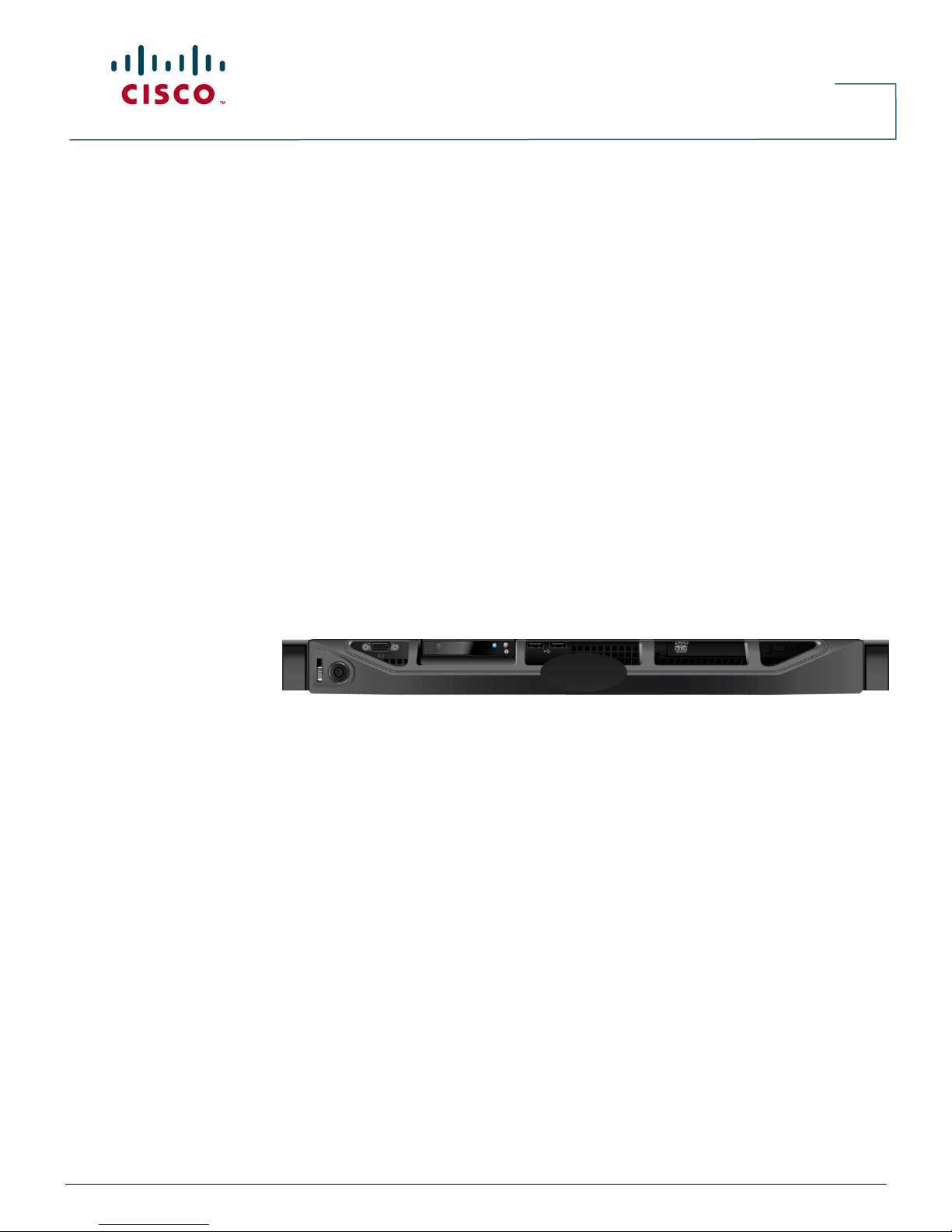
Figure 1. Model D-PCG1000 PowerKEY CAS Gateway (image may vary from actual product and specification)
Features
●
Creates Integrated PowerKEY Conditional Access ECMs
●
Complies with the Simulcrypt 3.0 Interface
●
Supports 1000 Broadcast Sessions at a 4- to 15-second cryptocycle
●
Reports all DVB ECMG-to-SCS and EIS-to-SCS errors using alarms to the DNCS. An alarm
is generated if the SCS stops requesting new ECMs
●
Contains two 10/100/1000BASE-T network interfaces for remote provisioning, control,
status monitoring, and alarms
Data Sheet
© 2011 Cisco and/or its affiliates. All rights reserved. This document is Cisco Public Information. Page 2 of 4
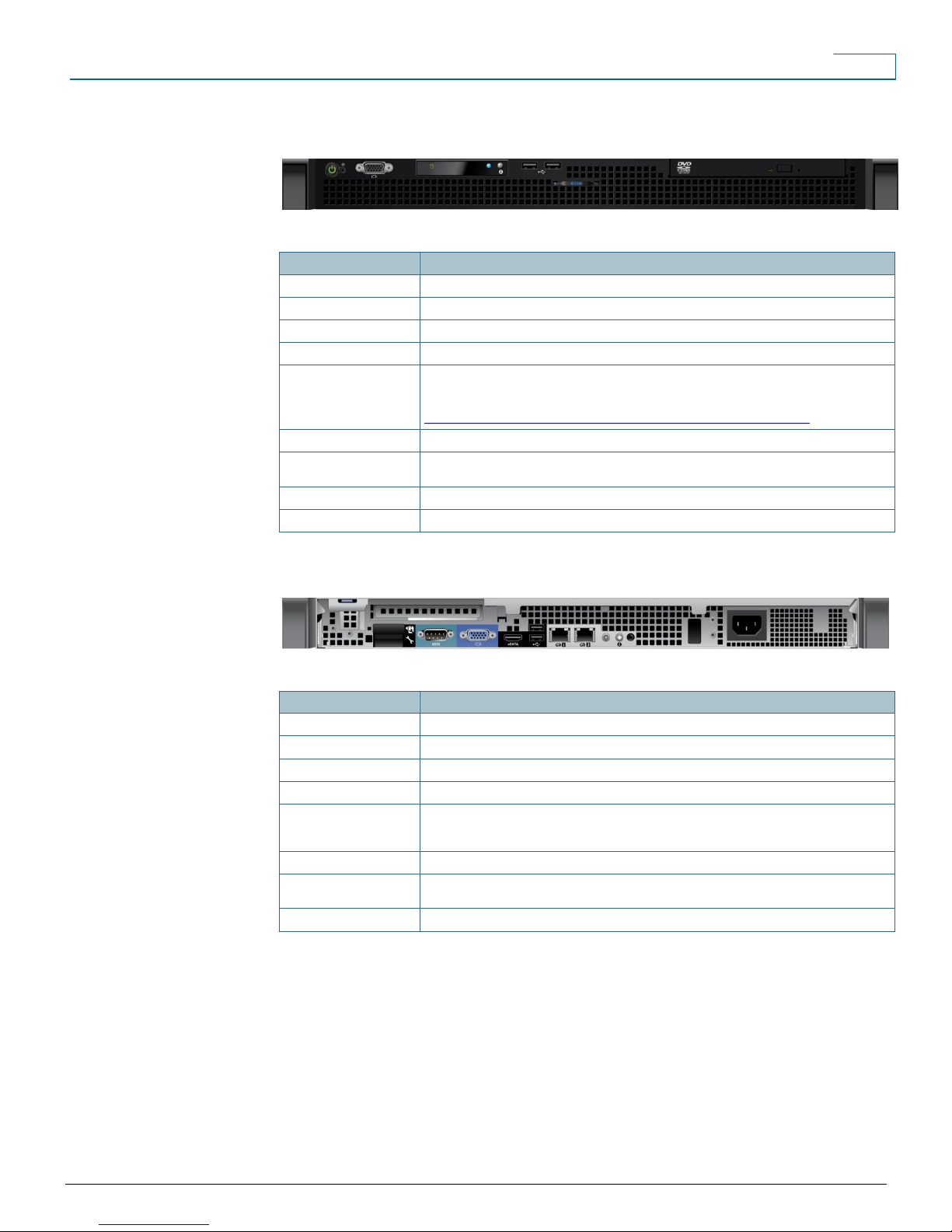
Feature
Description
Power Button
On/Off button
Restart Switch
System restart
Video Connector
Monitor connection
Hard Drive Activity LED
Hard drive access indication
Diagnostic Indicators (4)
Four diagnostic indicators; display error codes during system startup*
*For details about system diagnostics refer to the online document, Dell™ PowerEdge™ R210
Systems Hardware Owner’s Manual, which is located at:
http://support.dell.com/support/edocs/systems/per210/en/HOM/HTML/index.htm
System Status Indicator
Status indicator (blue light = normal operation; amber light = system needs attention)
System Identification
Button
System ID light. Push to illuminate light on both front and rear panels
USB 2.0 Connectors (2)
Peripheral device connection
Optical Drive (optional)
Optional CD/DVD drive
Feature
Description
Serial Port Connector
Serial I/O connection
Video Connector
Monitor connection
eSATA Connector
eSATA storage device connection
USB 2.0 Connectors (2)
Peripheral device connection
Ethernet Connectors (2)
Network connections:
1 = eth0
2 = eth1
System Status Indicator
Status indicator (blue light = normal operation; amber light = system needs attention)
System Identification
Button
System ID light. Push to illuminate light on both front and rear panels
Power Connector
AC power cord connection
Figure 2. Model D-PCG1000 PowerKEY CAS Gateway Front Panel with Bezel Removed (image may vary
from actual product and specification)
Table 1. Front Panel Features
Figure 3. Model D-PCG1000 PowerKEY CAS Gateway Back Panel (image may vary from actual product
and specification)
Table 2. Back Panel Features
 Loading...