

Page 1

OL-29163-01
Cisco Model DPC3939 DOCSIS 3.0
16x4 Wireless Residential Voice
Gateway
Us er Guide
Page 2

Page 3

Please R ead
Important
Read this entire guide. If this guide provides installation or operation instructions,
give particular attention to all safety statements included in this guide.
Page 4

Notices
T rademark Acknowledgm ents
Cisco and the Cisco logo are trademarks or registered trademarks of Cisco and/or its
affiliates in the U.S. and other countries. To view a list of Cisco trademarks, go to this
URL: www.cisco.com/go/trademarks. DOCSIS is a registered trademark of Cable
Television Laboratories, Inc. EuroDOCSIS, EuroPacketCable, and PacketCa ble a re
trademarks of Cable Television Laboratories, Inc. The Wi-Fi Protected Setup mark is
a mark of the Wi-Fi Alliance. Wi-Fi Protected Setup is a trademark of the Wi-Fi
Alliance.
Other third party trademarks mentioned are the property of their respective owners.
The use of the word partner does not imply a partnership relationship between
Cisco and any other company. (1110R)
Publication Disclaimer
Cisco Systems, Inc. assumes no responsibility for errors or omissions that may
app ea r in this publication. We reserve the right to change this publication at any
time without notice. This document is not to be const rued as conferring by
implication, estoppel, or otherwise any license or right under any copyright or
pat ent , whether or not the use of any information in this document employs an
invention claimed in any existing or later issued patent.
Disclaimer
The maximum performance for wireless is derived from IEEE Standard 802.11
specifications. Actual performance can vary, including lower wireless network
ca pacity, data t hroughput rate, range and coverage. Performa nce depends on many
factors, conditions and variables, including distance from the access point, volume of
network traffic, building materials and construction, operating system used, mix of
wireless products used, interference and other adverse conditions.
Software and Firmware Use
The software described in this document is protected by copyright law and
furnished to you under a license agreement. You may only use or copy this software
in accordance with the terms of your license agreement.
The firmware in this equipment is protected by copyright law. You may only use the
firmware in the equipment in which it is provided. Any reproduction or distribution
of this firmware, or any portion of it, without our express written consent is
prohibited.
Page 5

Copyright
© 2013 Cisco Systems, Inc. All rights reserved.
Informa tion in this publication is subject to change without notice. No part of this
publication may be reproduced or transmitted in any form, by photocopy,
microfilm, xerography, or any other means, or incorporated into any information
retrieval system, electronic or mechanical, for any purpose, without the express
permission of Cisco Systems, Inc.
Page 6
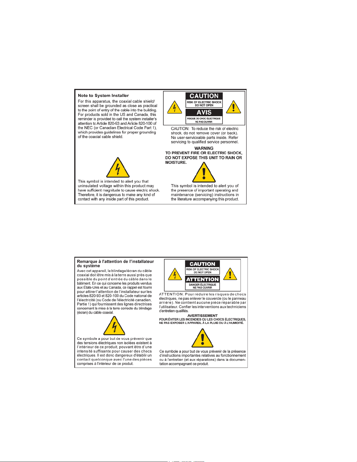
Notice to Installer s
The servicing i nstructions in this notice a re for use by quali fi ed ser vi ce personnel only. To reduce the
ri sk of electric shock, do not perform any servicing other than tha t contained in the operating
instructions, unless you are qualified to do so.
Notice à l’atten t ion des installateurs d e réseaux câblés
Les instructions r elatives a ux inter ventions d ’ entretien, fournies d ans la pr ésente notice, s’a d ressent
exclusivement au personnel technique quali fi é. Pour réduire les risques d e chocs électr iques, n’ effectuer
aucune interventi on autr e que cel les d écr ites dans le mod e d 'emploi et les instr uctions rel atives au
foncti onnement, à moins que vous ne soyez quali fi é pour ce fai re.
Page 7
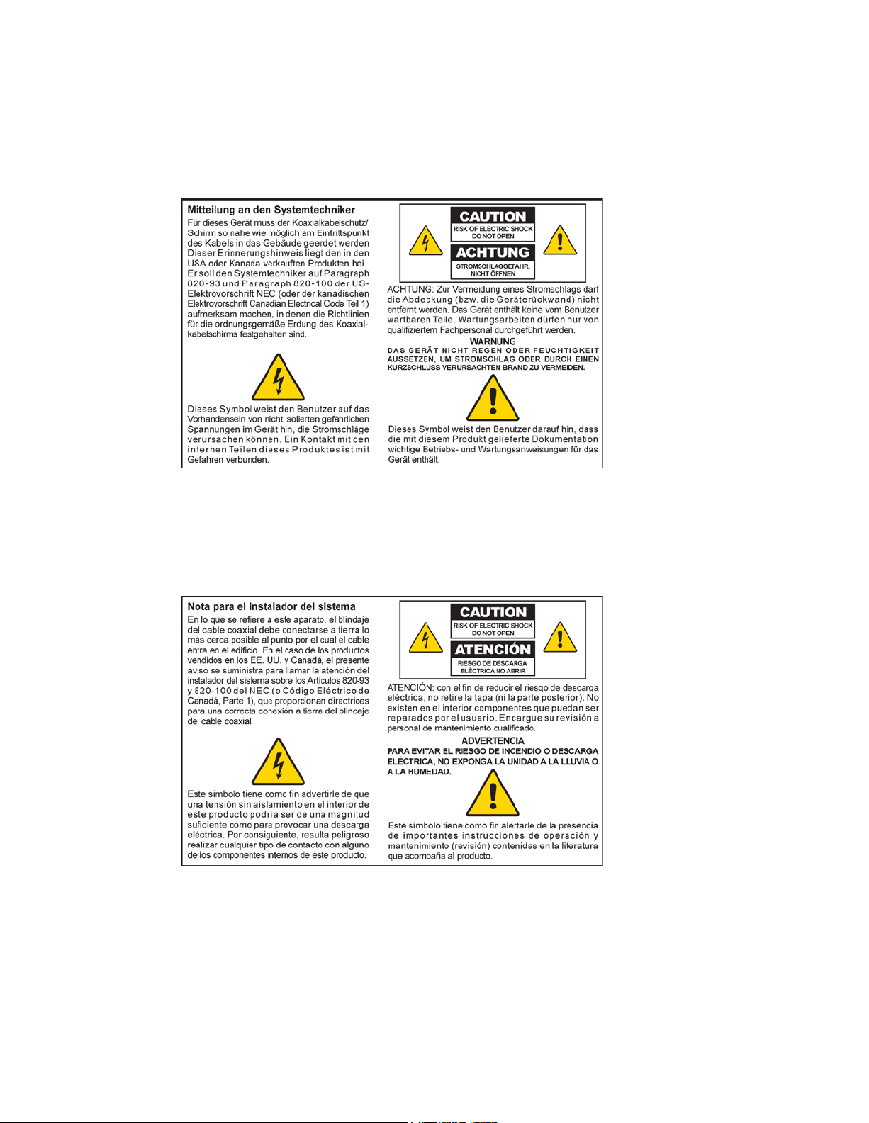
Mitteilung für CA TV -Techniker
Die in dieser Mitteilung aufgeführten Wartungsanweisungen sind ausschließlich für qualifiziertes
Fachper sonal bestimmt. Um d ie Gefahr eines el ektrischen Schlags zu reduzier en, sollten Si e keine
Wartungsarbeiten durchführen, die nicht ausdr ücklich in d er B edienungsanl eitung aufgeführt si nd,
außer Sie sind zur Durchführung solcher Arbeiten qualifiziert.
Aviso a los instaladores de sistem as CA TV
Las instr ucciones d e repara ción contenida s en el presente aviso s on pa ra uso exclusivo por par te d e
personal de mantenimiento cualificado. Con el fin de r educir el riesgo d e d escarga eléctri ca , no real ice
ninguna otra operación de reparación distinta a las contenidas en las instrucciones de funcionamiento, a
menos que posea la cualificación necesaria para hacerlo.
20080814_Installer820_Intl
Page 8

Page 9

OL-29163-01 iii
Contents
IMPORTANT SAFETY INSTRUCTIONS v
United States FCC Compliance xi
CE Compliance xiii
About This Guide xv
Chap ter 1 Introducing the Residential Gateway 1
Introduction ......................................................................................................................... 2
What's In th e Carto n? .......................................................................................................... 4
Front Panel Description ...................................................................................................... 5
Top Panel Desc ription......................................................................................................... 7
Bottom Panel Desc riptio n ................................................................................................... 8
Back Panel Desc riptio n ....................................................................................................... 9
Chap ter 2 Installing the Residential Gateway 11
Installation P reparations................................................................................................... 12
Install the Residential Gateway........................................................................................ 17
Install the Battery .............................................................................................................. 20
MoCA Installatio n Guidelines ......................................................................................... 22
Cha pt er 3 Co nfi g urin g th e R esi de nti al Gatew ay 25
Configure Wireless Settings ............................................................................................. 26
Chapter 4 Operation of Front Panel Indicators 37
Initial Power Up, Calibration, and Registration (AC Power applied) ........................... 38
Normal Op era tio ns (AC Pow er Applied) ....................................................................... 40
Special Co nditio ns ............................................................................................................. 41
Page 10

Contents
iv OL-29163-01
Chap ter 5 M aintaining the Battery 43
Location of the Battery ...................................................................................................... 44
Battery Ma i ntenanc e ......................................................................................................... 45
Chapte r 6 Troubleshooting the Residential Gateway 47
Fre que nt ly Ask ed Quest io ns ............................................................................................ 48
Common Troubleshooting Issues .................................................................................... 54
Tips for Improv ed Performa nce ....................................................................................... 56
Chap ter 7 Customer Information 57
Page 11

IMPORTANT SAFETY INSTRUCTIONS
OL-29163-01 v
IMPORTANT SAFETY INSTRUCTIONS
1)
Read these ins tr uctions.
4)
Follow all instructions.
5)
Do not use this apparatus near water.
eat sources such as radiators, heat registers, stoves, or other
10)
Protect the power cord from being walked on or pinched particularly at plugs,
12) Use only with the car t, stand, tripod, bra cket, or table speci fi ed by the
manufacturer, or sold with the apparatus. When a cart is used, use caution
13)
Unplug this apparatus during lightning storms or when unused for long periods of
14)
Refer a ll servicing to qual ified service personnel. Servicing is requir ed when the
apparatus has been exposed to rain or moisture, does not operate normally, or has
WARNING: Av oi d e le ctr ic shock and fir e ha za rd! If this product conne cts to coaxia l
cable wiring, be sure the cable system is grounded (earthed). Grounding provides
2) Keep these i nstructi ons.
3) Heed all warnings.
6) Clean only with dr y cloth.
7) Do not block a ny ventilation openings. Install in a ccorda nce with the ma nufacturer's
instructions.
8) Do not insta ll near a ny h
apparatus (including amplifiers) that produce heat.
9) Do not d efeat the safety purpose of the pol ariz ed or ground ing-type plug. A
polarized plug has two blades with one wider than the other. A gr ounding-type
plug has two blades and a third grounding prong. The wide blade or the third
prong is provided for your safety. If the provided plug does not fit into your outlet,
consult an electr ician for replacement of the obsol ete outlet.
convenience recepta cl es, and the point w her e they exi t from the a pparatus.
11) Only use a ttachments/a ccessories specified by the ma nufacturer.
when moving the ca rt/apparatus combination to avoi d i njury from
tip-over .
time.
apparatus has been damaged in any way, such as a power-suppl y cor d or pl ug is
damaged, liquid has been spilled or objects have fallen into the apparatus, the
been d ropped.
P ower Source W arni ng
A label on this product indicates the correct power source for this product. Operate this product only
from an electrical outlet with the voltage and frequency indicated on the product label. If you are
uncertain of the type of power supply to your home or business, consult your service provider or your
local power company.
The AC inlet on the unit must remain a ccessible and operable at all times.
Ground the Product
some protection against voltage surge s and b uilt-up static charges.
Page 12
IMPORTANT SAFETY INSTRUCTIONS
vi OL-29163-01
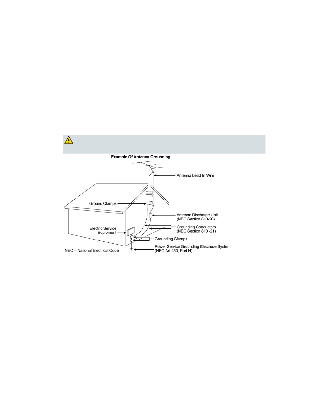
Outdoor Grounding System
WARNI NG: Avoid ele ctric sho ck a nd fire hazard! Do not locate an outside antenna
If this product connects to an outd oor a ntenna or cable system, be sure the a ntenna or cable system is
grounded (earthed). This provides some protection against voltage surges and built-up static charges.
Article 810 of the National Electric Code (NEC) ANSI/NFPA No. 70-1990, provides the following
information:
Grounding of the mast and supporting structure
Grounding the lea d-in w ire to an antenna d ischa rge unit
Size of the grounding conductors
Location of the antenna-d ischa rge unit
Connecti on to grounding electrodes
Requi rements for the grounding electrod es (see the foll ow ing a ntenna grounding dia gr a m as
recommended by NEC ANSI/NFPA 70)
system in the vicinity of ove rhea d powe r lines or power circuits. Touching power line s
or circuits might b e f ata l.
P rotect the P roduct from Lightni ng
In add ition to disconnecting the AC pow er from the wall outlet, disconnect the signal inputs.
Verify the Power Source from the On/Off Power Light
When the on/off power light is not illumina ted , the a ppar atus may still be connected to the power
source. The li ght may go out w hen the apparatus is turned off, regardless of whether it is still plugged
into an AC power source.
Page 13

IMPORTANT SAFETY INSTRUCTIONS
OL-29163-01 vii
Eli mi nate AC Power/Mains Overloads
WARNING: Avoid e lec tr i c shoc k and fir e haz a r d! Do not overload AC p ower/ma ins,
WARNI NG: Ther e is danger of explosion if the battery is mishandled or incorrectly
replaced. Replace only with the same type of battery. Do not disassemble it or attempt
outlets, extension cords, or integral convenience receptacles. For products that require
battery power or other power sources to operate them, refer to the operating
instr uctions f or those p roducts.
Handling Disposable Batteries
This product may contain a rechargeable Lithium-Ion battery to provide stand-by opera tion in the
event of a n AC pow er fa ilure.
Heed the following warning, follow the Battery Safety and Battery Disposal instructions below, and see
the instructions later in this guid e for handling, replacing, and d isposing of the ba ttery.
to recharge it outside the syste m. Do not crush, puncture, dispose of in fir e , shor t the
external contacts, or expose to water or other liquids. Dispose of the battery in
accordance with local regulations and instr uctions from your service provider.
Batter y Safety
Inser t batter ies correctl y. T her e ma y be a r isk of expl osion if the batteri es a r e incor rectly inserted.
Do not attempt to recharge ‘disposable’ or ‘non-reusable’ batteri es.
Please follow instructions provided for charging ‘rechargeable’ batteries.
Replace ba tteries w ith the sa me or equiva lent type tha t we recommend.
Do not ex pose ba tteries to excessive hea t (such a s sunlight or fir e).
Do not expose batteries to temperatures above 100°C (212°F).
Batter y D i sp o sal
The batteries may contain substances that could be harmful to the environment.
Recycle or dispose of batteries in accordance with the battery manufacturer’s instructions and
local/national disposal and recycling regulations.
The batteries may contain perchlorate, a known hazardous substance, so special handling and
disposal of this product might be necessary. For more information about perchlorate and best
ma nagement practices for perchlor ate-containi ng substa nce, see
www.dtsc.ca.gov/hazardouswaste/perchlorate
Provide Ventilation and Select a Location
Remove all pa ckaging ma ter ial befor e a pplying pow er to the product.
Make certain to operate this unit only in a vertical position.
Do not place this apparatus on a bed, sofa, rug, or similar surface.
Do not place this apparatus on an unstable sur fa ce.
Page 14

IMPORTANT SAFETY INSTRUCTIONS
viii OL-29163-01
Do not insta ll this a ppar atus in an enclosure, such as a bookcase or r ack, unless the installation
WARNING: Av oi d e le ctr ic shock and fir e ha za rd! Do not expose this pr oduct to
WARNING: Avoid ele ctr ic shock a nd f ire haz a r d! Unp lug this product b e f ore cle a ning.
Do not use a liquid cleaner or an aerosol cleaner. Do not use a magnetic/static cleaning
WARNING: Av oi d e le ctr ic shock and fir e ha za rd! Never push obje cts thr ough the
WARNI NG: Avoid electric shoc k! Do no t open the cover of this product. Op e ning or
provides proper ventilation.
Do not place entertainment devices (such as VCRs or DVDs), lamps, books, vases with liquids, or
other objects on top of this product.
Do not block ventilation openings.
Opera ting E nvi ronm ent
This product is designed for operation indoors with a temperature range from 32° to 104° F (0° to 40°C).
Each product should have adequate spacing on all sides so that the cooling air vents on the chassis are
not blocked.
P rotect from E xpos ure to Moisture and Fore ign O bject s
dripping or splashing liq uids, rain, or moisture. Objects f illed with liquids, such as
vases, should not be placed on this apparatus.
device (dust remover) to clean this p r oduct.
openings in this p roduct. Foreign objects can cause electrical shorts that can result in
electric shock or fire.
Service Warnin gs
removing the cover may e xp ose you to dangerous voltage s. If you ope n the cover, your
warranty will be void. This product contains no user-serviceable parts.
Check Product Safety
Upon completion of any service or repai rs to thi s pr oduct, the s ervice technicia n must perform safety
checks to d etermine that this product is in proper operating cond ition.
P rotect the P roduct W hen Movi ng It
Alwa ys d isconnect the power source w hen moving the appara tus or connecti ng or d isconnecting
cabl es.
Page 15

IMPORTANT SAFETY INSTRUCTIONS
OL-29163-01 ix
T el ephone E quipm e nt Not ice
CAUTI ON: To r educe the r isk of fir e, us e onl y No. 26 AWG or la r ger
When using your tel ephone equipment, bas ic sa fety precautions should a lways be followed to r educe
the risk of fire, electric stock and injury to persons, including the following:
1. Do not use this product near water, for example, near a bath tub, wash bowl, kitchen sink or laundry
tub, i n a wet basement or near a swimming pool.
2. Avoi d usi ng a telephone (other than a cordless type) d uring an el ectrical stor m. T her e ma y be a
remote risk of electric shock from lightning.
3. Do not use the telephone to repor t a gas l eak in the vicini ty of the lea k.
Important: Inter connected telecommunication terminal equipment (for example via RJ11) must be UL
listed and the connections must be made in accordance with Article 800 of the NEC
telecommunica tion line cord.
SAVE THESE INSTRUCTI ONS
20110316_Cable_Safety
20110316_Modem No Battery_Safety
20110316_Modem with Battery_Safety
20110316_Modem DSL_Safety
Page 16

Page 17

Unite d Stat es FCC Compliance
OL-29163-01 xi
United S tates FCC Compliance
This device has been tested and found to comply with the limits for a Class B digital device,
pursuant to part 15 of the FCC Rules. These limits are designed to provide reasonable
protection against such interference in a residential installation. This equipment generates,
uses, and can radiate radio frequency energy. If not installed and used in accordance with the
instructions, it may cause harmful interference to radio communications. However, there is
no guarantee that interference will not occur in a particular installation. If this equipment
does cause harmful interference to radio or television reception, which can be determined by
turning the equipment OFF and ON, the user is encouraged to try to correct the interference
by one or more of the followin g measures:
Reorient or relocate the receiving antenna.
Increase the separation between the equipment and receiver.
Connect the equipment into an outlet on a circuit different from that to which the
receiver is connected.
Consult the service provider or an experienced radio/television technician for help.
Any changes or modifications not expressly approv ed b y Cisco Sy stems, Inc., could void the
user's authority to operate the equipment.
The information shown in the FCC Declaration of Conformity paragraph below is a
requirement of the FCC and is intended to supply you with information regarding the FCC
approval of this device. The phone numbers listed are for FCC-related questions only and not
intended for questions regarding the connection or operation for this device. Please contact your
service provider for any questions you may have regarding the operation or installation of this devi ce.
De cla ration of Conform it y
This device complies with Part 15 of FCC
Rules. Operation is subject to the following
two condition s: 1) the device may not cause
harmful interference, and 2) the device must
accept any interference received, including
interference that may cause undesired
operation.
Canada EMI R egulation
This Class B digital apparatus complies with Canadian ICES-003.
Cet appareil numérique de la class B est conforme à la norme NMB-003 du Canada.
Residential Gateway
Model(s): DPC3939
Manufactured by:
Cisco Systems, Inc.
5030 Sugarloaf Parkway
Lawrenceville, Georgia 30044 USA
Page 18

United Sta te s FCC Complianc e
x ii OL-29163-01
RF Exposure Statements
Note: This transmitter must not be co-located or operated in conjunction with any other
antenna or transmitter. This equipment should be installed and operated with a minimum
distance of 7.9 inches (20 cm) between the radiator and your body. For products available in
the USA/Canada market, only channels 1-11 can be operated. The selection of other channels
is not possible.
US
This system has been evaluated for RF exposure for humans in reference to ANSI C 95.1
(American National Standards Institute) limits. The evaluation was based in accordance with
FCC OET Bulletin 65C rev 01.01 in compliance with Part 2.1091 and Part 15.27. The minimum
separation distance from the antenna to general bystander is 7.9 inches (20 cm) to maintain
compliance.
Canada
This system has been evaluated for RF exposure for humans in reference to Canada Health
Code 6 (2009) limits. The evaluation was based on evaluation per RSS-102 Rev 4. The
minimum separation distance from the antenna to general bystander is 7.9 inches (20 cm) to
maintain compliance.
20100527 FCC DSL_Domestic
Page 19
CE Compliance
OL-29163-01 xiii
CE Compliance
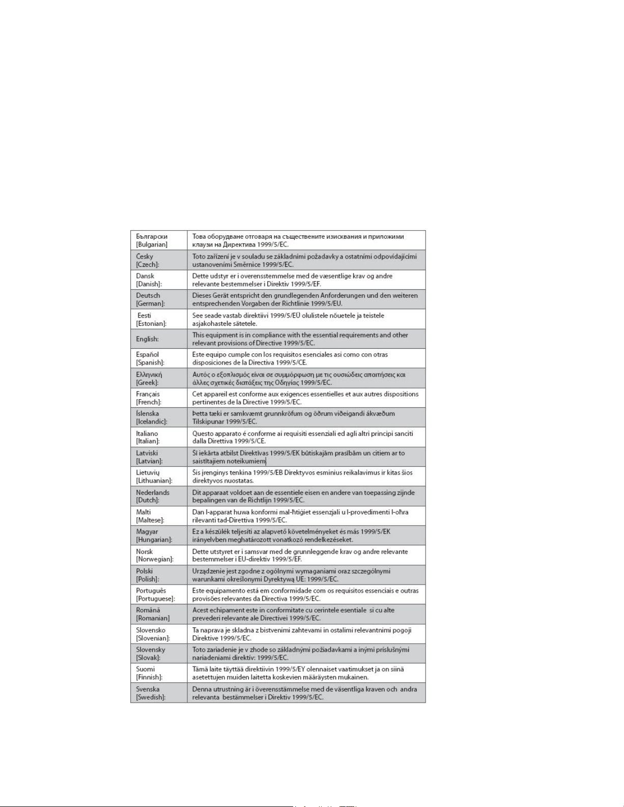
De cla ration of Conform it y with Regard to the EU Directive 1999/5/E C (R&TTE Directive)
This declaration is only valid for configurations (combinations of software, firmware and
hardware) supported or provided by Cisco Systems for use within the EU. The use of
software or firmware not supported or prov ided b y Cisco Systems may result in the
equipment no longer being compliant with the regulatory requirements.
Page 20

CE Compliance
x iv OL-29163-01
Note: The full declaration of conformity for this product can be found at
http: //www.cisco.com/ we b/co nsumer/ sup port/comp lia nce_info.htm l.
The following standards were applied during the assessment of the product against the
requirements of the Directive 1999/5/EC:
Radio: EN 300 328
EMC: EN 301 489-1 and EN 301 489-17
Safety: EN 60950 and EN 50385
The CE mark and class-2 identifier are affixed to the product and its packaging. This product
conforms to the following Europe an directives:
National Restrictions
This product is for indoor use only .
France
For 2.4 GHz, the output power is restricted to 10 mW EIRP when the product is used
outdoors in the band 2454 - 2483.5 MHz. There are no restrictions when used in other parts of
the 2.4 GHz band. Check http://www.arcep.fr/ for more details.
-1999/5/EC
Pour la bande 2,4 GHz, la puissance est limitée à 10 mW en p.i.r.e. pour les équipements
utilisés en extérieur dans la bande 2454 - 2483,5 MHz. Il n'y a pas de restrictions pour des
utilisations dans d'autres parties de la bande 2,4 GHz. Consultez http://www.arcep.fr/ pour
de plus amples détails.
Italy
This product meets the National Radio Interface and the requirements specified in the
National Frequency Allocation Table for Italy. Unless this wireless LAN product is operating
within the boundaries of the owner's property, its use requires a “general authorization.”
Please check http://www.comuni cazi oni.it/i t/ for m ore details.
Questo prodotto è conforme alla specifiche di Interfaccia Radio Nazionali e rispetta il Piano
Nazionale di ripartizione delle frequenze in Italia. Se non viene installato all 'interno del
proprio fondo, l'utilizzo di prodotti Wireless LAN richiede una “Autorizzazione Generale”.
Consultare http://www.comuni cazi oni. it/i t/ per maggiori dettagli.
Latvia
The outdoor usage of the 2.4 GHz band requires an authorization from the Electronic
Communications Office. Please check http://www.esd.lv for more details.
2,4 GHz frekvenču joslas izmantošanai ārpus telpām nepieciešama atļauja no Elektronisko
sakaru direkcijas. Vairāk informācijas: http://www.esd.lv.
Note: The regulatory limits for maximum output power are specified in EIRP. The EIRP level
of a dev ice can b e calculated by adding the gain of the antenna used (specified in dBi) to the
output power available at the connector (specified in dBm).
20110311_CE_Gateway
Page 21

About This Guide
OL-29163-01 xv
About This G uide
Introduction
Welcome. This guide provides instructions and recommendations for placing,
installing, configuring, operating, maintaining, and troubleshooting t he Cisco
Model DPC3939 DOCSIS 3.0 16x4 Wireless Residential Voice Gateway (DPC3939).
Purpose
This guide covers the Model DPC3 939 D OCSIS 3.0 16x4 Wireless Residential Voice
Gateway. All features described in this guide are standard to this Residential
Gateway unless otherwise noted as an optional feature.
Audience
This guide is written for the home subscriber.
Document Version
®
This is the second release of this document. In addition to minor editorial changes,
this release adds the defa ult MoCA userna me a nd password.
Page 22

Page 23

OL-29163-01 1
1 Chapter 1
Int r oduci ng the R es ide nt ia l
Gateway
Introduction
This chapter provides an overview of Residential Gateway features,
indica tors, and connectors to help you become familiar with the
Residential Gateway and the benefits it offers. This chapter also lists
the accessories and equipment that are provided with the Residential
Gateway so you can verify that you received all of these items.
In Thi s Cha pte r
Introduction ..........................................................................................2
What's In th e Carto n? ...........................................................................4
Front Panel Description .......................................................................5
Top Panel Desc ription..........................................................................7
Bottom Panel Desc riptio n ....................................................................8
Back Panel Desc riptio n ........................................................................9
Page 24

Chapter 1 Intr oduc i ng the Res ident ial Gate way
2 OL-29163-01
Introduction
The Cisco® Model DPC3939 DOCSIS 3.0 16x4 Wireless Residential Voice Gateway
(DPC3939) is an advanced, high-performance home gateway that combines Ethernet,
Voice over IP (VoIP), router, and wireless access point technologies in a single device
to provide a cost-effective voice and networking solution for Connected Home and
Managed Home experiences.
This chapter lists the benefits and features of the model DPC3939 Residential
Gateway. Illust rations a nd descriptions of t he connection ports, buttons, a nd LED
indicators are also provided.
Benefits and Features
Your new Residential Gateway offers the following outstanding benefits and
features.
DOCSIS
Eight bonded downstream channels with a total throughput in excess of 300
Mbps
Compliant with DOCSIS 3.0, 2.0, 1.1, and 1.0 standards to deliver high-end
performance and reliability
Enhanced pa cket processing technology to maximize performance
Connections
Multimedia over Coax Alliance (MoCA) networking over coaxial cable in the
home
Four 10/100/1000BASE-T Ethernet ports to provide wired connectivity
High-performance broadband Int ernet connectivity to energize your online
experience
Two ATA Ports with SIP Client support
Supports separate phone numbers on each port
Dual universal serial bus (USB) host support (contact your service provider for
more information)
WPS, including a push-button switch to activate WPS for simplified and secure
wireless setup
Page 25

Introduction
OL-29163-01 3
Des ign a nd Func t ion
Embedded network management client for simplified out of the box setup and
configuration
Local device management via web-based GUI
Management
User-configurable Parental Control blocks access to undesirable Internet sites
Simplified, unified home network ma nagement
Advanced firewall technology deters hackers and protects the home network
from una uthorized a ccess
Allows au tomatic software upgrades by your service provider
DOCSIS-compliant secure software downloads
Page 26

Chapter 1 Intr oduc i ng the Res ident ial Gate way
4 OL-29163-01
What' s In the Carton?
When you receive your Residential Gateway, you should check the equipment and
accessories to verify that each it em is in the carton and t hat each item is undama ged.
The carton contains the following items:
One Model DPC39 39 Residentia l
Gateway
One Lithium Ion cartridge battery
(May not be provided with all
products.)
If any of these items are missing or damaged, please contact your service provider
for assistance.
One A C p ower cord
Notes:
A battery is needed only when voice service is enabled on the Residential
Gateway.
You need an optional cable signal splitter and additional standard RF coaxial
cables if you want to connect a VCR, a Digital Home Communications Terminal
(DHCT) or a set-top converter, or a TV to the same ca ble connection as your
Residential Gateway.
If your product supports telephone service, cables and other equipment needed
for telephone service must be purchased separately. Contact your service
provider to inquire about the equipment and cables you need for telephone
service.
Page 27

Front Panel Description
OL-29163-01 5
Front Panel Descriptio n
The front panel of your Residential Gateway provides LED status indicators that
indicate how well and at what state your Residential Gateway is operating. See
Operation of Front Panel Indicators (on page 37), for more information on front
panel LED stat us indicator functions.
Residential Gateway
1 POWER—ON, power is applied to the Residential Gateway. OFF when power is
off to the Residentia l Gateway.
2 US/DS—ON, the Residential Gateway is exchanging dat a with the cable
network. Blinking indica t es the downstream scan is in progress.
3 ONLINE—ON, the Residential Gateway is registered on the network and fully
operational. OFF indicates the Residential Gatewa y has not registered on the
network.
4 2.4 GHz—ON, the wireless access point is operational. Blinking indicates that
data is being transferred over the wireless connection. OFF indicates that the
wireless access point is not enabled.
Page 28

Chapter 1 Intr oduc i ng the Res ident ial Gate way
6 OL-29163-01
5 5 GHz—ON, the wireless access point is operational. Blinking indicates that data
is being transferred over the wireless connection. OFF indicates that the wireless
access point is not enabled.
1
6 TEL
—ON indica tes telephony service is enabled. Blinks when line 1 is in use.
OFF indicates t hat phone service for TEL 1 is not enabled.
7 TEL
2
—ON indicates telephony service is enabled. Blinks when line 2 is in use.
OFF indicates t hat phone service for TEL 2 is not enabled.
8 BATTERY ( optional model only)—ON indicates that the battery is charged.
Blinking indicates that the battery charge is low. OFF indicates the unit is
operating from ba ttery power, the battery charge is depleted, or the battery is
defective or missing.
Notes:
After the Residential Gateway is successfully registered on the network, the
POWER, US/DS, and ONLINE LEDs illuminate continuously to indicate that the
Residential Gateway is active and fully operational.
The high-speed data operation is disabled when operating on ba ttery power;
only the telephone service (if available on this model) is active when operating
on battery power.
LEDs may behave differently when the Residential Gateway is running on
battery power (without AC power). Most LEDs are disabled if the unit is
operating on battery power. In this mode, t he P OWER LED blinks to indicate
that the unit is operating under battery power.
The Residential Gateway shou ld only run on bat tery power when AC power has
failed. If t he POWER LED indicates that t he unit is running on battery power,
but the AC power has not failed, verify that the power cord is plugged into a
working AC outlet.
Page 29

Top Panel De sc r iption
OL-29163-01 7
Top Panel D escription
Two buttons and LEDs on the top panel of the Residential Gateway show the status
of the Wireless Protected Setup (WPS) and Page features.
1 WPS (WIRELESS PROTECTED SETUP)—OFF (normal condition) Wireless
Protected Setup is not active. Blinking indicates the button has been pressed and
WPS is active so that a new wireless client can be added to the wireless network.
2 PAGE—OFF (normal condition) indicates the Page feature is not active. Slow
blinking indicates the unit is on and communicating with registered telephone
receivers (only CAT-iq 2 .0 handsets). Fast blinking indicates t hat the unit is
transmitting data to registered handsets. To register the unit with a handset,
press the button for 1 5 seconds. After the unit and handset have registered, press
the button for up to 3 seconds to page registered handsets; press the button again
for up to 3 seconds to stop paging registered handsets.
Important: Use the Page feature only with Cordless Advanced Technology
(CAT-iq 2.0 handsets). To learn more about CA T-iq 2.0 handsets, contact your
service provider.
Page 30

Chapter 1 Intr oduc i ng the Res ident ial Gate way
8 OL-29163-01
Bottom Panel Descriptio n
The bottom panel of your Residential Gateway contains a product information label
and the door to the battery compartment.
1 LABEL—product information label
2 BATTERY—battery compartment door
Page 31

Back Panel Descript ion
OL-29163-01 9
Back Panel D escriptio n
The following illustration identifies the back panel components on the Cisco
Residential Gateway. Descriptions for each component follow the illustration.
Important: Do not connect your PC to both the Ethernet and USB ports (future
capability) at the same time.
Important: Use only the power cord provided with your Residential Gateway.
CAUTION:
Avoid damage to your equipment. Only use the power cord that is provided
with your Residential Gateway .
1 RESET—A momentary pressing (1-2 seconds) of this switch restarts the device.
To press this switch, insert a thin object , such as a paper clip, int o the RESET
port; then p res s and hold the switch for more than ten seconds to reset all
settings to their factory-settings and then restart the device.
Page 32

Chapter 1 Intr oduc i ng the Res ident ial Gate way
10 OL-29163-01
CAUTION:
The RESET button is for maintenance purposes only. Do not use unless
instructed to do so by your service provider. Doing so may cause you to lose
any settings you have selected.
2 USB (optional for some models)—Connects the Residential Gateway to selected
devices. For models that support USB, the default is one USB port.
3 TEL1 and Alarm/Tel2—RJ-11 telep hone ports for connecting telephones, fax
machines, and/or an analog home alarm system.
4 ETHERNET—Four RJ-45 Ethernet ports allow connect ion to the Ethernet port on
your PC or network device.
5 MoCA/Cable—F-connector connects to your home coax network to provide
Cable and MoCA service.
6 POWER—Connects the Residential Gateway to the AC wall outlet.
Page 33

OL-29163-01 11
2 Chapter 2
Installing the Residential
Gateway
MoCA Installation Guide li nes ..........................................................22
Introduction
This chapter describes how to properly install the Residential Gateway
and to connect the Residential Gateway to a computer a nd other
devices.
In Thi s Cha pte r
Installation P reparatio ns ....................................................................12
Install the Residential Gateway.........................................................17
Install the Battery ...............................................................................20
Page 34

Chapter 2 Inst all ing the Resident ial Gateway
12 OL-29163-01
Installati on P reparatio ns
Before installing the Residential Gateway, make sure that your system meets or
exceeds the requirements listed in this section. Also, make sure that you have
prepared your home and home devices as described in this section.
What Are the System Requirements for Internet S ervice?
To ensure that your Residential Gateway operates efficiently for high-speed Internet
service, you must have a n Internet-capable PC, Mac, or Internet appliance equipped
with an Ethernet port.
Note: You will also need an active cable input line and an Int ernet connection.
Minimum Hardw a re Re quire me n t s f or a P C
A PC with a P entium MMX 133 or greater processor recommended
32 MB of RAM
Ethernet port
Minimum Hardw a re Re quire me n t s f or a Macintos h
32 MB of RAM
Ethernet port
Minimum Soft w a re Re quire men ts f or a n E t he rne t C onne c t ion
Operating system with web browser, TCP/IP protocol
Page 35

Insta llation Pre para tions
OL-29163-01 13
What Are the Requirements for T elephone S ervice?
If you intend to use the Residential Gateway for digital telephone service, verify that
your home meets or exceeds a ll of the following requirements.
Max imum Number of Tele phone s
The RJ-11 telephone-style connectors on the Residential Gateway can each provide
telephone service to multiple telephones, fax machines, and analog modems.
The maximum number of telephone devices connected to each RJ-11 port is limited
by t he tota l Ringing Load of the telephone devices tha t are connected. Many
telephone devices are marked with a Ringer Equiva lent Number (REN). Each
telephone port on the Residential Gateway can support up to a 5 REN load.
The sum of the REN load on all of the telephone devices attached to each port must
not exceed 5 REN.
Telephone Device Types
You can use telephone devices that are not labeled with a REN number, but the
maximum number of attached telephone devices cannot be accurately calculated.
With telephone devices that are not labeled, each device should be connected and
the ring signal should be tested before adding more devices. If too many telephone
devices are at tached a nd the ring signal can no longer be heard, telephone devices
should be removed until the ring signal works properly.
Telephones, fax machines, and other telephone devices use the center 2 pins of the
RJ-11 connectors to connect to your primary service.
Dialing Re quire ment s
All your telephones should be set to use Dual-Tone Multi-Frequency (DTMF)
dialing. Pulse dialing may not be supported by your local service provider.
T e le phone Wiring Requirement s
The Res idential Ga tewa y supports connecting to the interior telephone wiring a s
well as connect ing directly to a telephone or fax ma chine. The maximu m dist ance
from the unit to the most distant telephone device must not exceed 10 00 feet (300
meters). Use 26-gauge twisted-p air, or larger, telephone wiring.
Important: Connection t o an exist ing or a new permanently installed home
telephone wiring network should be completed by a qualified installer or at the
direction of your telephone service provider.
Page 36

Chapter 2 Inst all ing the Resident ial Gateway
14 OL-29163-01
What T ypes of Service Accounts Do I Need?
Depending upon the features your service provider offers, you ma y need to establish
one or both of the following accounts:
A high-speed Internet access account, if your Residential Gateway supports an
Internet connection
An account for telephone service, if your Residential Gateway supports digital
telephone service
Refer to one of the following topics to learn more about the types of service accounts
that you may need to establish.
High-Speed Internet Access Account
If you do not have a high-speed Internet access account, your service provider will
set up your account and become your Internet Service Provider (ISP). Internet access
enables you to send and receive e-mail, access the World Wide Web, and receive
other Internet services.
You will need to give your service provider information about the Residential
Gateway in order to use the high-speed Internet feature that this product offers.
Refer to Information Your Service Provider Needs (on page 14) to learn how to locate
the information your service provider needs to establish a high-speed Internet access
account for the Residential Gateway
I Alrea dy Ha v e a High-Speed Internet Access Account
If you ha ve an existing high-speed Internet access account, you will need to give
your service provider the serial number and MAC address of the Residential
Gateway in order to use the high-speed Internet feature that this product offers.
Refer to Information Your Service Provider Needs (on page 14) to learn how to locate
this information.
Inform ation Your Servic e Prov ider N eeds
You will need to give your service provider the following information, which is
printed on the bar code label attached to the device:
The Serial Number (S/N) of the Residentia l Gateway. The serial number consists
of a series of nine digits.
The Media Access Control (CM MAC) address of the Residential Gateway. The
CM MAC address consists of a series of 12 alphanumeric characters.
The Media Access Control (MAC) address of the Residential Gateway media
terminal adapter (MTA MAC). The MTA MAC address consists of a series of 12
alphanumeric chara cters.
Page 37

Insta llation Pre para tions
OL-29163-01 15
The following illustration shows a typical bar coded label; the image may vary from
the label on the actual product.
Write down these numbers in the spaces provided:
Serial Number _______________________
CM MAC Address ________________________
MTA MAC Address ________________________
Telephone Servi ce
You will need to establish a telephone account with your local service p rovider t o
use your Residential Gateway for telephone service.
When you contact your service provider, you may be able to transfer your existing
telephone numbers. If not, then your cable telephony service provider will assign a
new telephone number to enable your voice service(s). Discuss these options with
your telephony service provider.
Page 38

Chapter 2 Inst all ing the Resident ial Gateway
16 OL-29163-01
Where Is the Best Location for My Residential Gateway?
The ideal location for your Residential Gateway is where it has access to outlets and
other devices. Think about the layout of your home or office, and consult with your
service provider to select the best location for your Residential Gatewa y. Read this
user guide thoroughly before you decide where to place your Residential Gateway.
Consider these recommendations:
Choose a location close to your computer if you will also use the Residential
Gateway for high-speed Internet service.
Choose a loca tion that is near a n existing RF coaxia l connection to elimina te the
need for an additional RF coaxial outlet.
Choose a location that is relatively protected from accidental disturbance or
harm, such as a closet, basement, or other protected area.
Choose a location so that there is plenty of room to guide the cables away from
the Residential Gateway without straining or crimping them.
Choose a location that allows adequate ventilation around the Residential
Gateway.
Choose a location for the Residential Gateway that is adjacent to your telephone
equipment if you pla n on connecting your phone directly to the Residential
Gateway.
Note: If you are using the Residential Gatewa y to provide service to several
telephones, a professional installer can connect the Residential Gateway to your
existing home telep hone wiring.
Page 39

Install the Residential Gateway
OL-29163-01 17
Install the Residenti al Gateway
This section describes how t o connect your Residential Gateway to support the
services that the Residential Gateway offers.
Connect Devices to the Residential Gateway
Professional installation may be available. Contact your local service provider for
further assistance.
The following diagram illustrates one of the various networking options that are
available to you.
Connect the Residential Gateway
The following ins talla tion procedure ensures prop er setup and configuration for the
Residential Gateway.
1 Choose an appropriate and safe location to install the Residential Gateway (close
to a power source, an active cable connection, your PC-if using high-speed
Internet, and your telephone lines -if using VoIP). For assistance, refer to Where Is
the Best Location for My Residential Gateway? (on pa ge 16).
Page 40

Chapter 2 In st all ing the Resident ial Gateway
18 OL-29163-01
WARNING:
To prevent possible damage to equipment, disconnect any other telephone
service before connecting your Residential Gateway to the same wires.
Hazardous electrical voltages can exist on the telephone, Ethernet, or coax
cable wiring. Be sure to disconnect AC power from all devices while
installing your service.
All wiring and connections must be properly insulated to prevent
electrical sho ck.
Telephone connections to an installed home telephone wiring network
should be done by a qualified installer. The cable telephone service
pro vider may offer pro fessional installation and connection to the ho me
telephone wiring network. A fee may be charged for this service.
2 Power off your PC and other networking device; then, unplug them from the
power source.
3 Connect the active RF coaxia l cable from your service provider to the coa x
connector la beled MoCA/CABLE on the back of the Residential Gateway.
Note: To connect a TV, DHCT, set-top, or VCR from the same cable connection,
you will need to install a cable signal splitter (not included). Always check with
your service provider before using a splitter as a splitter may degrade the signal.
For more information about a MoCA installation, see MoCA Installation
Guidelines (on page 22).
4 Connect your PC to the Residentia l Gateway using one of the following methods:
Ethernet Connection. Connect one end of an Ethernet cable to the Ethernet
port on your PC, and connect the other end to the Ethernet port on the back
of the Residential Gateway.
Wireless Connection. Make sure that your wireless device is powered up.
You will need to associate your wireless device with the Residential Gateway
once the Residential Gateway is operational. Follow the directions provided
with your wireless device for associating with a wireless access point. Make
sure that either the 2.4 GHz or t he 5 GHz indicator is ON.
For more information about the factory default configuration of t he
DPC3939, see Configure Wireless Settings (on page 26).
5 If your Residential Gateway supports digital telephone service (VoIP), connect
one end of a telephone jumper cable (not included) to a telephone outlet in your
home or to a telephone or fax ma chine. Then connect the other end of the jumper
cable to the appropriate RJ-11 Tel1 or Alarm/Tel2 port on t he back of the
Residential Gateway.
Notes: Telephones that require electrical connectors other than RJ-11 may require
an external adapter (sold separately).
Page 41

Install the Residential Gateway
OL-29163-01 19
6 Locate the AC power cord provided with your Residentia l Gateway. Connect the
barrel connector end of the power cord int o the power inp ut on the back of the
Residential Gateway. Then, plug the other end of t he power cord into an AC
outlet.
The Residential Gateway will perform an automatic search to locate and sign on
to the broadband data network. This process may take up to 2-5 minutes. The
Residential Gateway will be ready for use when the P o we r, US/DS, and Online
LEDs on the front panel of t he Residential Gateway stop blinking and remain on
continuously.
7 Plug in and power on your PC and other home network devices. If one or more
of these devices uses wireless networking, the 2.4 GHz or 5 GHz LED on the
Residential Gateway should be on or blinking.
8 At t his point, the installation is complete, and you can begin surfing the Internet.
Note: If your PC does not have Internet access, refer to How Do I Configure
TC P/IP Protocol? (on page 48) for information on how to configure your PC for
TCP/IP. For Internet devices other than PCs, refer to the DHCP or IP Address
configuration section of the User Guide or Operations Manual for thos e devices.
Page 42

Chapter 2 In st all ing the Resident ial Gateway
20 OL-29163-01
Install the Battery
WARNING:
Your Residential Gateway may include one rechargeable Lithium-Ion battery to
provide stand-by operation in the event of an AC power failure. We recommend that
you install the battery before mounting the Residential Gateway to a wall (if you
decide to do so) and before installing the Residential Gateway in your home.
It is possible to use the Residential Gateway without the battery. However, if you
choose to operate the Residential Gateway without a battery, you will not have
telephone service during a power outa ge.
For information on batt ery ma intenance, refer to Maintaining the Battery (on pa ge
43).
Installing the Battery
Installing the battery requires no tools. Follow these instructions to install the
battery.
Fully charged high-capacity rechargeable batteries should be handled with
care. Replace only with the battery recommended by the manufacturer. Do not
disassemble it or attempt to recharge the battery outside the system. Do not
crush, puncture, dispose of in a fire, short the external contacts, or expose to
high temperature or immerse in water or other liquids. Dispo se of the battery
in accordance with local regulations and instructions fro m your service
provider.
1 Turn the Residential Gateway so that you are facing the side with the battery
compartment.
2 Gently release the latch to open the battery cover and gain access to the battery
compartment.
Page 43

I n st all th e B at t ery
OL-29163-01 21
3 Insert the battery into the battery compartment. Do not force the battery into the
compartment, but be sure to press the battery all the way in until it seats fully.
Important: Take care to position the battery correctly. Insert the battery only as
shown in the following illustration.
4 Close the battery compartment door.
Important: After you install the Residential Gateway and plug it into an AC
electrical outlet as described in Install the Residential Gateway (on page 17), it
ca n take a s long as 2 4 hours for t he batt ery to cha rge fully. However, you can
begin using your high-speed Internet and telephone service immediately after
installation. See Normal Operations (AC Power Applied) (on page 40) for
information on how the LEDs on the front of the Residentia l Gat eway indica te
the state of the battery charge.
Page 44

Chapter 2 Inst all ing the Resident ial Gateway
22 OL-29163-01
MoCA Installation Guidelines
MoCA is an in-home distribution technology that leverages the coax cable networks
that exist in more t ha n 90% of US households. MoCA is an attractive option because
it provides a relatively low-cost method of getting DVR and other multimedia
sharing video services to multiple TVs within the home without additional cable
installation.
MoCA operates over the physical layer of the home coaxial cable plant in the 1 0001500 MHz spectrum. Its infrastructure begins a t the service provider’s drop cable at
the first passive splitter connected to the home coax network.
Recommended Installation Guidelines
The following guidelines are recommended for a home network prior to installation.
The maximum cable distance supported between the network coordinator and
the last outlet is 300 feet.
The maximum attenuation permitted between nodes is 25 dB.
Branches within the home-network should flow from secondary splitters.
Assess the home network and determine the data rates between coax outlets.
Sectionalize the individual MoCA nodes to validate proper operation of the
device’s MoCA interface.
Evalua te and certify the integrity of the coax cable plant between MoCA nodes.
Page 45

Mo CA Ins t a lla tio n Guid e line s
OL-29163-01 23
Identify sources of noise and interference on the MoCA spectrum.
Re-qua lify additional coax outlets to support MoCA-enabled devices and
services.
Pre-Installation Instructions
Prior to installing MoCA, complete the following tasks:
1 Contact your service provider and ensure that the Residential Gateway is
enabled for MoCA services.
2 Ensure that a MoCA filter has been has been installed by your service provider at
the home’s entry point, as shown in the f ollowing illustration:
3 To log-in to the Residentia l Gateway, enter http://10.0.0.1 in the web address
(URL) field of any browser and press the Enter key. Then enter the following
when prompted:
Username: admin
Password: password
4 From the menu options, go to Gateway/Connections/MoCA and ensure that
MoCA is set to enable.
5 If you have not already done so, connect the coaxial cable from a wall cable
outlet within the home network to the MoCA/Cable port on the rea r p anel of the
Residential Gateway.
6 If you have not already done so, connect the AC power cord provided with your
Residential Gateway. Connect the barrel connector end of the power cord into
the power input on the back of the Resident ia l Gateway. Then, plug the other
end of the power cord into an AC outlet.
Page 46

Chapter 2 Inst all ing the Resident ial Gateway
24 OL-29163-01
The Residential Gateway will perform an automatic search to locate and sign on
to the broadband data network. This process may take up to 2-5 minutes. The
Residential Gateway will be ready for use when the P o we r, US/DS, and Online
LEDs on the front pa nel of the residential gateway stop blinking and remain on
continuously.
7 Wait a few seconds for the device to de discovered. When discovered, a n LED
labeled 2.4 GHz or 5 GHz should turn on. At this point, a MoCA node should be
active in the network.
8 If you have not already done so, connect an Ethernet compatible device (for
example, a set-top, computer, or PlayStation) to the Ethernet port on the
Residential Gateway. The ONLINE LED should turn on a nd the device should
be ready to use.
9 Follow the steps above to connect additional Residential Gateways to the
network; note that up 15 residential gateways can be a dded to a MoCA network.
10 From the user interfa ce, you can monitor a limited number of parameters
associa ted with the MoCA network. You may login at any time to check for
status or for troubleshooting purposes.
Page 47

OL-29163-01 25
iffer from the pages shown on
3 Chapter 3
C onfi guri ng t he Re si dent i al
Gateway
Introduction
This chapter provides instructions for configuring the Residential
Gateway to operate correctly. Exa mples of the configuration pages are
for illustration purposes only and may d
your Residentia l Gateway.
Important: If you are not familiar with the network configura tion
procedures detailed in this chapter, contact your service provider
before attempting to change any of the Residential Gateway settings.
In Thi s Cha pte r
Configure Wireless Settings ..............................................................26
Page 48

Chapter 3 Configuring the Residential Gateway
26 OL-29163-01
Configure Wireles s Setting s
Setting up the Wireless Residential Gateway for wireless communication provides
you with the freedom to connect to the Int ernet f rom any loca tion within range of
the Wireless Access Point (WAP) without having to us e wired connections. This
section provides procedures for configuring the WAP to meet your needs. These
options are available as tabs on the Gateway > Connection > WiFi page.
Private WiFi Network - Use this page to choose the wireless network mode that
the Wireless Residential Gateway will use to set up other basic features including
Security mode and Network Password.
MAC Filter Settings- Use this page to configure MAC address filtering for your
wireless network separately for 2.4 GHz and 5 GHz networks.
Add WPS Client - Use this p age to manually s et up and connect WPS clients
with the WP S P IN method and Push Button.
Log in to the Residential Gateway
1 On your PC, open the web browser that you prefer to use.
2 In the web address (URL) field, enter http://10.0.0.1 a nd press the Enter key.
3 When prompted enter the following username and pa ssword:
Username: admin
Password: password
Page 49

Configure Wireless S ettings
OL-29163-01 27
Private WiFi Network
From the Gateway > Connection > WiFi page, click the Edit but tons in 2.4 GHz or
5GHz network to configure Network Name (SSID), Mode, Security Mode. Channel
Selection and Network Password and Enable/Disabling the wireless network or
Broadcasting Network Name.
Page 50

Chapter 3 Configuring the Residential Gateway
28 OL-29163-01
Configure the Residential Gateway for the 2.4 GHz Wireless Network
Network Name for 2.4
last 4 digits of the cable modem MAC address, which is found
This section describes how to configure wireless settings for the 2.4 GHz wireless
network.
Use the descriptions and instructions in the following table to manually configure
the basic settings for wireless communication for the Residential Gateway. After you
make your selections, click Save Settings to apply your changes or Restore Default
Settings to set values back to factory default values.
Field Label Description
Wireless Netwo rk
Use this setting to Enable or Disable the wireless
network.
GHz (SSID 1)
The SSID is the name of your wireless network. The SSID is
use d b y wireless technolog y to identify y our network from
other wireless networks in the area. The SSID can be up to 32
characters long .
The factory-set SSID is HOME-XXXX-2.4 where XXXX is the
on the label located on the b ottom of the Residential Gateway.
The factory-set SSID is a unique identity and does n ot need to
be changed unless y ou ch oose to do so.
Page 51

Configure Wireless S ettings
OL-29163-01 29
Field Label Description
Channel Selection
Show Netwo rk
Mode
Security Mode
Choose one of these options for the network mode:
802.11 g/n
802.11 b/g/n
Important: When TKIP authentication only is selected, B/G/N
Mixed network mode is not available.
Choose one of these options for the security mode:
Open (risky )
64 bits (5 Ascii characters or 10 Hex digits)
128 bits (13 Ascii characters or 26 Hex digits)
WPA-PSK(TKIP) (8 to 63 Ascii characters or 64 Hex digits)
WPA-PSK(AES) (8 to 63 Ascii characters or 64 Hex digits)
WPA2-PSK(TKIP) (8 to 63 Ascii characters or 64 Hex digits)
WPA2-PSK(AES) (8 to 63 Ascii characters or 64 Hex digits)
WPA2-PSK(TKIP/AES) (8 to 63 Ascii characters or 64 Hex
digits)
WPAWPA2-PSK(TKIP/A ES) recommended (8 to 63 Ascii
characters or 64 Hex digits)
Note: Not all wireless adapters support WPA2. WPA is
supported across a wider range of devices. Whether you use
WPA or WPA2, make sure to use a "strong" passphrase. A
strong passphrase is a string of random characters at least 21
characters in length.
Automatic. Select Automatic (factory default) to have channel
selected for you.
Manual. Select Manual to select channels from the Channel
field.
Channel
Network Password
Password
When the Manual option is chosen for Channel Selection, use
this field to select a channel from 1 through 11.
Note: Only channels 1, 6 and 11 are n on-overlapping channels.
Depending upon Security Mode selected, the Network
Password can have different requirements. The factory-set
password value can be found on the label located on the
bottom of your Residential Gateway.
To make the Network Password become visible to the user or
not. Every time the page is opened, this box is unchecked for
security reasons.
Page 52

Chapter 3 Configuring the Resid ential G ateway
30 OL-29163-01
Field Label Description
Gateway transmits or advertises its presence to other wireless
Broadcast Network
When this box is checked (factory default), the Residential
Name (SSID)
devices. Client devices can automatically detect the access
point when this is enabled.
If you want to hide your ne twork from wireless clients, leave
this box unselected. When your network is hidden, you will
need to configure each of your wireless client devices
manually.
Configure the Residential Gateway for the 5 GHz Wireless Network
This section describes how to configure wireless settings for the 5 GHz wireless
network.
Page 53

Configure Wireless S ettings
OL-29163-01 31
Use the descriptions and instructions in the following table to manually configure
other wireless networks in the area. The SSID can be up to 32
the basic settings for wireless communication for the Residential Gateway. After you
make your selections, click Save Settings to apply your changes or Restore Default
Settings to set values back to factory default values.
Field Label Description
Wireless Netwo rk
Network Name for 5
GHz (SSID 2)
Mode
Security Mode
Use this setting to Enable or Disable the wireless network.
The SSID is the name of your wireless network. The SSID is
use d b y wireless technolog y to identify y our network from
characters long .
The factory -set SSID is HOME-XXXX-5 where XXXX is the last
4 digits of the cable modem MA C address, which is foun d on
the label located on the bottom of the Residential Gateway.
The factory-set SSID is a unique identity and does not need to
be changed unless y ou ch oose to do so.
Choose one of these options for the network mode:
802.11 a/n
801.11 n
Important: The following Security mode is recommended:
WPAWPA2-PSK (TKIP/AES).
Choose one of these options for the security mode.
Open (risky )
WEP 64 bits (5 Ascii characters or 10 Hex digits)
WEP 128 bits (13 Ascii characters or 26 Hex digits)
WPA-PSK(TKIP) (8 to 63 Ascii characters or 64 Hex digits)
WPA-PSK(AES) (8 to 63 Ascii characters or 64 Hex digits)
WPA2-PSK(TKIP) (8 to 63 Ascii characters or 64 Hex digits)
WPA2-PSK(AES) (8 to 63 Ascii characters or 64 Hex digits)
WPA2-PSK(TKIP/AES) (8 to 63 Ascii characters or 64 Hex
digits)
WPAWPA2-PSK(TKIP/A ES) recommended (8 to 63 Ascii
characters or 64 Hex digits)
Note: Not all wireless adapters support WPA2. WPA is
supported across a wider range of devices. Whether you use
WPA or WPA2, make sure to use a strong passphrase. A strong
passphrase is a string of random characters at least 21
characters in length.
Page 54

Chapter 3 Configuring the Residential Gateway
32 OL-29163-01
Field Label Description
Gateway transmits or advertises its presence to other wireless
If you want to hide your network from wireless clients, leave
Channel Selection
Channel
Network Password
Show Netwo rk
Password
Broadcast Network
Name (SSID)
Automatic. Select Automatic (factory default) to have channel
selected for you.
Manual. Select Manual to select channels from the Channel
field.
When the Manual option is chosen for Channel Selection, use
this field to select a channel from 40, 48, 153, and 161.
Depending upon Security Mode selected, the Network
Password can have different requirements. The factory-set
password value can be found on the label located on the
bottom of your Residential Gateway.
To make the Network Password become visible to the user or
not. Every time the page is opened, this box is unchecked for
security reasons.
When this box is checked (factory default), the Residential
devices. Client devices can automatically detect the access
point when this is enabled.
this box unselected. When your network is hidden, you will
need to configure each of your wireless client devices
manually.
Page 55

Configure Wireless S ettings
OL-29163-01 33
Configure MAC A ddress Filtering
Use this page to configure MAC address filtering for your wireless network
separately for 2.4 GHz and 5 GHz networks. This feature allows you to give access
privileges to certain wireless clients.
Page 56

Chapter 3 Configuring the Residential Gateway
34 OL-29163-01
Use the descriptions and instructions in the f ollowing table to configure MAC
address filtering for your wireless network. After you make your selections, click
Save Filter Settings to apply your changes.
Field Description
SSID
Click the SSID drop-down arrow to select the SSID to which
you would like to apply the filtered clients:
Allow All- allow ac c es s to all the clients included in WiF i
Cont r ol Lis t
Allow- allow acc ess to the selected clients in W iFi Cont r ol
Li st
Deny- deny acc ess to the selected clients in WiF i Contr ol
Li st
Manually-Added WiFi
Enter the name of the device in the Device Name field.
Devices
Device Name
Manually-Added WiFi
Devices
MAC Address
Enter the MAC address of the device in the MAC Address
fields.
Click ADD. The WiFi client is added to the WiFi Control List.
Conf igure and C onnec t WiFi Protected Setup Clients
Use this page to manually set u p and connect WPS clients, WPS PIN method and
Push Button.
Page 57

Configure Wireless S ettings
OL-29163-01 35
Use the descriptions and instructions in the following table to manually set up and
connect WPS clients, WPS PIN method and Push Button. After you make your
selections, click Pair to connect your wireless device.
Field Description
SSID
WiFi Protected
Setup (WPS)
WPS PIN Method
Connection Options
Wireless Clients PIN
Click the SSID drop-down arrow to select the SSID to connect
a client to using WPS.
Enable - Click to make the WPS mechanism activ e.
Disable - Click to make the WPS mechanism inactive.
Enable - Click to make the WPS PIN Method active.
Disable - Click to make the WPS PIN Method inactive.
Click the Connection Options drop-down arrow to se lect the
connection method to use. When selecting the Push Button
method, click PAIR after the client has asked the WPS button
be pushed. The wireless device will connect within two
minutes.
To pair, select the Pair button and your wireless device will
connect within two minutes. You may also press the [push]
button on this device. The Wireless Clients PIN, found from
client, needs to be entered in this field and click PAIR.
Page 58

Page 59

OL-29163-01 37
4 Chapter 4
Oper ation of Front Panel
Indicators
Special Co nditions ..............................................................................41
Introduction
This section describes the behavior of the front panel indicators when
the Residential Gateway is first powered up, during normal
operations, and in special conditions.
In Thi s Cha pte r
Initial Power Up, Calibration, and Registration (AC Power
applied) ...............................................................................................38
Normal Op era tio ns (AC Pow er Applied) ........................................40
Page 60

Chapter 4 Operation of Front Panel Indicators
38 OL-29163-01
Initial Power Up, Calibration, and Registration (AC
Registration
Front Panel
Self
Downstream
Downstream
Ranging
Requesting IP
Request High
1
POWER
On
On
On
On
On
On 2 US/DS
On
Blin king
On
On
On
On
3
ONLINE
On
Off
Off
Off
Off
Blin king
4
2.4 GHz
On
On or Blinking
On or Blinking
On or
On or Blin king
On or Blinking
5
5 GHz
On
On or Blinking
On or Blinking
On or
On or Blinking
On or Blinking
6
TEL1
On
Off
Off
Off
Off
Off
7
TEL2
On
Off
Off
Off
Off
Off
8
BATTERY
P ow er appl ied)
The following chart illustrates the sequence of steps and the corresponding
app ea ra nce of the Residential Gateway front panel LED status indica tors during
power up, calibrat ion, and regis tration on the network when AC power is applied to
the Residential Gateway. Use this chart to troubleshoot the power up, calibration,
and registration process of your Residential Gateway.
Note: After the Residential Gateway completes Step 7 (Data Network Registration
Complete), the Residential Gateway proceeds immediately to Normal Operations.
See Normal Operations (AC Power applied) (on page 40).
Front Pa nel LED Sta tus Indic ators Duri ng I nitia l P ow er Up, Ca libra tion, a nd
Part 1, High Speed Data Registration
Step: 1 2 3 4 5 6
Indicator
Tes t
Scan
Signal Lock
Blin king
Blin king
On – When battery is charged
Blinks – When battery charge is low
Off – When there is no battery in the unit
Address
Speed Dat a
Provis i oning Fi le
Page 61

Init ia l Powe r U p, C a libra tion, and Re gist r at ion ( AC Power a pplied)
OL-29163-01 39
Registration
Part 2, Telephone Registration
Front Panel
Data Network
Requesting
Request
Restarting Voice
Telephone
1
POWER
On
On
On
On
On 2
US/DS
On
On
On
On
On 3
ONLINE
On
On
On
On
On
4
2.4 GHz
On or
On or Blinking
On or Blinking
On or Blinking
On or Blinking
5
5 GHz
On or
On or Blinking
On or Blinking
On or Blinking
On or Blinking
6
TEL1
Off
Blin king
Off
Blin king
On 7
TEL2
Off
Off
Blin king
Blin king
On
8
BATTERY
Front Pa nel LED Sta tus Indic ators Duri ng I nitia l P ow er Up, Ca libra tion, a nd
Step: 7 8 9 10 11
Indicator
Registration
Complete
Blin king
Blin king
On – When battery is charged
Blinks – When battery charge is low
Telephone IP
Address
Telephone
Provis i oning Fi le
Off – When there is no battery in the unit
Se rvi c e
Registration
Complete
Page 62

Chapter 4 Operation of Front Panel Indicators
40 OL-29163-01
Norm al Operations (AC Pow er Applied)
The following chart illustrates the appearance of the Residential Gateway front panel
LED status indicators during normal operations when AC power is applied to the
gateway.
Front Panel LED Status Indicators During No rmal Conditions
Fr ont Pa ne l Indicator Normal Operations
1
POWER On
2
US/DS On
3
ONLINE On
4
5
2.4 GHz
5 GHz
On - When the wireless access point is enabled and
operational
Blinks - When data is being transferred between the CPE
and the wireless home gateway
Off - When the wireless access point is disabled by the
user
On - When the wireless access point is enabled and
operational
Blinks - When data is being transferred between the CPE
and the wireless home gateway
Off - When the wireless access point is disabled by the
user
6
TEL1
7
TEL2
BATTERY
8
On - When telephony service is enabled
Blinks - When line 1 is in use
On - When telephony service is enabled
Blinks - When line 2 is in use
On – When battery is charged
Blinks – When battery charge is low
Off – When there is no battery in the unit
Page 63

Special Conditions
OL-29163-01 41
Special C ondition s
The following chart describes the appearance of the Residential Gateway front panel
LED sta tus indicators during specia l conditions t o show when you ha ve been denied
network access.
Front Panel LED Status Indicators During Special Conditions
Fr ont Pa ne l Indicator Network Access Denied
1
POWER
2
US/DS
3
ONLINE
4
2.4 GHz
Slow Blinking
(once per second)
Slow Blinking
(once per second)
Slow Blinking
(once per second)
Slow Blinking
(once per second)
5
5 GHz
Slow Blinking
(once per second)
6
7
8
TEL1
TEL2
BATTERY
Off
Off
On
Page 64

Page 65

OL-29163-01 43
Introduction
5 Chapter 5
Maintaining the Battery
Ba t tery Mai ntenanc e ..........................................................................45
This chapter des cribes how to maintain and repla ce the battery that is
included with the Residential Gateway.
In Thi s Cha pte r
Location of the Battery .......................................................................44
Page 66

Chapter 5 Main t aini n g the Battery
44 OL-29163-01
Location of the Battery
The following illustration shows the location of the battery.
Page 67

Batt ery Maintenan ce
OL-29163-01 45
Battery Maintenanc e
If your Residential Gateway contains a battery backup feature, a high-capacity
rechargeable battery provides stand-by operat ion in the event of an A C power
failure. You can replace the ba ttery without the use of any tools.
WARNING:
Fully charged high-capacity rechargeable batteries should be handled with
care. Replace only with the battery recommended by the manufacturer. Do not
disassemble it or attempt to recharge the battery outside the system. Do not
crush, puncture, dispose of in a fire, short the external contacts, or expose to
high temperature or immerse in water or other liquids. Dispo se of the battery
in accordance with local regulations and instructions fro m your service
provider.
Charging the Ba t t e ry
The battery begins to charge automatically as soon as you attach the Residential
Gateway to the AC electrical outlet. When you first plug in the Residential Gateway,
the POWER LED status indicator illuminates.
Important: It may take as long as 24 hours for the battery to charge fully.
Removing and Re pla c ing t he Batte ry
Under normal circumsta nces, the battery should last for several years. The
BATTERY LED status indicator blinks to indicate that the battery should be
repla ced soon. Contact your service provider to obtain replacement batteries and for
disposal instructions.
Follow these steps to remove and replace the battery. You can remove and replace
the battery without disconnecting the AC power source.
1 Turn the Residential Gateway so that you are facing the side with the battery
compartment.
2 Gently release the latch to open the battery cover and gain access to the battery
compartment.
3 Grasp the plastic strip on the front of the battery and gently slide the battery
forward to remove it from the battery compartment.
Page 68

Chapter 5 Maintainin g the Battery
46 OL-29163-01
4 Insert a new battery into the battery compartment. Do not force the battery into
the compartment, but be sure to press the battery all the way in until it seats
fully.
5 Close the battery compartment door. The battery lock will automatically re-
engage.
Important: It can take as long as 24 hours for the battery to charge fully.
Note: Dispose of the battery in accordance with local regulations and
instruct ions from your service provider.
Using the Re s ide nt ia l G a t eway Without a Battery
If you want, you can use the Residential Gateway without a battery. If you need to
remove the battery, follow the procedures found in Removing and Replacing the
Battery (on page 45).
Important: If you choose to operate your Residential Gateway without a battery, you
risk losing your telephone service during a power outage.
Page 69

OL-29163-01 47
6 Chapter 6
Troubleshooting t he
Residential Gateway
Tips for Improv ed Performa nce ........................................................56
Introduction
This chapter des cribes the most common issues that may occur after
the Residential Gateway is installed and provides possible solutions
and tips for improved performance of the Residential Gateway.
In Thi s Cha pte r
Fre que nt ly Ask ed Questio ns .............................................................48
Common Troubleshooting Issues .....................................................54
Page 70

Chapter 6 Troubleshooting the Residential Gateway
48 OL-29163-01
Frequently Asked Q uestions
This section provides answers to common questions about the Residential Gateway.
How Do I Conf igure TC P /I P Protoc ol?
To configure TCP/IP protocol, you need to have an Ethernet Network Interface Card
(NIC) with TCP/IP communications protocol installed on your system. TCP/IP is a
communications prot ocol used to a cces s the Internet. This section contains
instructions for configu ring TCP/IP on your Internet devices to operate with the
Residential Gateway in Microsoft Windows or Macintosh environments.
TCP/IP protocol in a Microsoft Windows environment is different for each
operating system. Follow the appropriate instructions in this section for your
operating system.
Configuring T C P/ IP on Windows 7 Sy s tems
1 Open Network Connections by clicking the Start button, a nd then clicking
Control Panel.
2 In the Search box, type adapter, and then, under Network and Sharing Center,
click View network connections.
3 Right-click the connection that you wa nt to change, and then click Properties. If
you are prompted for an administrator password or confirmation, type the
password or provide confirmation. The Local Area Connection Properties
window opens.
4 Click the Networking tab.
5 Under This connection uses the following items, click either Internet Protocol
Version 4 (TCP/IPv4) or Internet Protocol Version 6 (TCP/IPv6), a nd then click
Properties.
6 To specify IPv4 IP address settings, do one of the following:
To get IP settings automatically using DHCP, click Obtain an IP address
automatically, a nd then click OK.
To specify an IP address, click Use the following IP address, and t hen, in the
IP address, Subnet mask, a nd Default gateway boxes, type the IP address
settings.
7 To specify IPv6 IP address settings, do one of the following:
To get IP settings automatically using DHCP, click Obtain an IPv6 address
automatically, and then click OK.
To specify an IP address, click Use the following IPv6 address, and then, in
the IPv6 address, Subnet prefix length, a nd the Default gateway boxes, type
the IP address settings.
Page 71

Frequently Asked Questions
OL-29163-01 49
8 To specify DNS server address settings, do one of the following:
To get a DNS server address automatically using DHCP, click Obtain DNS
server address automatically, and then click OK.
To specify a DNS server address, click Use the following DNS server
addresses, and then, in the Preferred DNS server and Alternate DNS server
boxes, type the addresses of the primary and secondary D NS servers.
9 To cha nge advanced DNS, WINS, and IP settings, click Advanced.
10 When you a re finished, click OK.
11 Try to access the Internet. If you cannot access the Internet, contact your service
provider for further assistance.
Configuring T C P/ IP on Windows XP Sy s tems
1 Click Start, and depending on your Start menu set up, choose one of the
following options:
If you are using the Windows XP Default Start Menu, select Connect to,
choose Show all connections, and t hen go to step 2.
If you are using the Windows XP Classic Start Menu, select Settings, choose
Network Connections, click Local Area Connection, and then go t o st ep 3.
2 Double-click the Local Area Connection icon in the LAN or High-Speed Internet
section of t he Network Connections window.
3 Click Properties in the Local Area Connection Status window.
4 Click Internet Protocol (TCP/IP), and then click Properties in the Local Area
Connect ion Properties window.
5 Select both Obtain an IP address automatically and Obtain DNS server address
automatically in the Internet Protocol (TCP/IP ) Properties window, and t hen
click OK.
6 Click Yes to restart your computer when the Local Network window opens. The
computer restarts. The TCP/IP protocol is now configured on your PC, and your
Ethernet devices are ready for use.
7 Try to access the Internet. If you ca nnot access the Internet, contact your service
provider for further assistance.
Configuring T C P/ IP on Mac intosh Systems
1 Click the Apple icon in the upp er-left corner of the Finder. Scroll down to
Control Panels, a nd then click TCP/IP.
2 Click Edit on the Finder at the top of the screen. Scroll down to the bottom of the
menu, and then click User Mode.
3 Click Advanced in the User Mode window, and then click OK.
4 Click the Up/Down selector arrows located to the right of the Connect Via
section of the TCP/I P window, and then click Using DHCP Server.
Page 72

Chapter 6 Troubleshooting the Residential Gateway
50 OL-29163-01
5 Click Options in the TCP/IP window, and then click Active in the TCP/IP
Options window.
Note: Make sure that the Load only when needed option is unch ecked .
6 Verify that the Use 802.3 option located in t he upper-right corner of the TCP/IP
window is unchecked. If there is a check mark in the option, uncheck the opt ion,
and t hen click Info in the lower-left corner.
7 Is there a Hardware Address listed in this window?
If yes, click OK. To close the TCP/IP Control Panel window, click File, a nd
then scroll down to click Close. You have completed this procedure.
If no, you must power off your Macintosh.
8 Wit h the power off, simultaneously press a nd hold down t he Command
(Apple), Option, P, a nd R keys on your keyboard. Keeping those keys pressed
down, power on you r Macintosh but do not release these keys until you hear the
Apple chime at least three times, then release the keys and let the computer
restart.
9 When your computer fully reboots, repeat steps 1 through 7 to verify that all
TCP/IP settings are correct. If your computer still does not have a Hardware
Address, contact your authorized Apple dealer or Apple technical support center
for further assistance.
How Do I Rene w the I P Addres s on My P C ?
If your PC cannot access the Internet after the Residential Gateway is online, it is
possible that your PC did not renew its IP address. Follow the appropriate
instructions in this section for your opera ting system to renew the IP address on
your PC.
Renewing the IP Addres s on Windows 7 Sy s tems
1 Click the Windows Start button.
2 Type cmd in the Search box. The cmd window opens.
3 Type ipconfig /renew and press Enter to renew the IP address of the computer.
Renewing the IP Addres s on Windows XP Sy s tems
1 Click Start, a nd then click Run. The Run window opens.
2 Type cmd in the Open field and click OK. A window with a command prompt
opens.
3 Type ipconfig /release at the C:/ prompt and press Enter. The system releases
the IP address.
4 Type ipconfig /renew at the C:/ prompt and press Enter. The system displays a
new IP address.
Page 73

Frequently Asked Questions
OL-29163-01 51
5 Click the X in the upper-right corner of the window t o close the Command
Prompt window. You have completed this procedure.
Note: If you cannot access the Internet, contact your service provider for further
assistance.
Renew ing the IP Address on Window s 95, 98, 98SE, and M E Sys tems
1 Click Start, a nd then click Run. The Run window opens.
2 In the Open field, type winipcfg and click OK. The IP Configuration window
opens.
3 Click the down arrow to the right of the top field, and select the Ethernet adapter
that is installed on your PC. The IP Configuration window displays t he Ethernet
ada pter information.
4 Click Release, and then click Renew. The IP Configuration window displays a
new IP a ddress.
5 Click OK to close the IP Configuration window and complete this procedure.
Note: If you cannot access the Internet, contact your service provider for further
assistance.
Renewing the IP Addres s on M ac intosh Sys tems
1 Close all open programs.
2 Open your Preferences folder.
3 Drag the tcp/ip preferences file to the Tras h.
4 Close all open windows and emp ty the Trash.
5 Restart your computer.
6 As your computer starts, simultaneously press and hold down the Command
(Apple), Option, P, a nd R keys on your keyboard. Keeping those keys pressed
down, power on your Macintosh but do not release these keys until you hear the
Apple chime at least three times; then, release the keys and let the computer
restart.
7 When your computer fully reboots, click the Apple icon in t he u pper-left corner
of the Finder. Scroll down to Control Panels, and t hen click TCP/IP.
8 Click Edit on the Finder at the top of the screen. Scroll down to the bottom of the
menu, and then click User Mode.
9 Click Advanced in the User Mode window, and then click OK.
10 Click the Up/Down selector arrows located to the right of the Connect Via
section of the TCP/I P window, and then click Using DHCP Server.
11 Click Options in the TCP/IP window, and then click Active in t he TCP/IP
Options window.
Note: In some cases, the Load only when needed option does not appear. If it
appears, select the option. A check ma rk appears in the option.
Page 74

Chapter 6 Troublesh oot ing the Residential Gateway
52 OL-29163-01
12 Verify that the Use 802.3 option located in t he upper-right corner of the TCP/IP
window is not selected. If there is a check mark in the option, select the option to
clear the check ma rk, a nd then click Info in the lower-left corner.
13 Is there a Hardware Address listed in this window?
If yes, click OK. To close the TCP/IP Control Panel window, click File, a nd
then scroll down to click Close.
If no, repeat these instructions from step 6 .
14 Reboot your computer.
What if I Don't Subscribe to Cable TV?
If cable TV is available in your area, data service may be made available with or
without subscribing to cable TV service. Contact your local service provider for
complete information on cable services, including high-speed Internet access.
How Do I A rrange f or Insta lla tion?
Call your service provider to inquire about professional installation. A professional
installation ensures proper ca ble connection to the Residential Gatewa y and to your
PC, and it ensures the proper configuration of a ll hardware and soft wa re set tings.
Contact your service provider for more information about installation.
How Does the Residential Gateway Connect to My C omputer?
The Residential Gateway connects to the 10/100/1000BASE-T Ethernet port on your
PC. To use the Ethernet interface, Ethernet cards available from your local PC or
office supply retailer, or from you r service provider. For best performance over an
Et hernet connection, your PC shou ld be equipp ed wit h a Gigabit Ethernet card.
Af ter My Residential Gateway Is Connect ed, How Do I Access the Internet?
Your local service provider becomes your Internet Service Provider (ISP). They offer
a wide range of services including e-ma il, chat, news, a nd information services. You r
service provider will provide the software you will need.
Can I W atch TV and Surf the Internet at the Sam e Time?
Absolutely! If you subscribe to cable television service, you can watch TV and use
your Residentia l Gateway at the sa me time by connecting your TV and your
Residential Gateway to the cable network using an optional cable signal splitter.
Page 75

Frequently Asked Questions
OL-29163-01 53
Can I Use my Existing Phone Number with th e Residential Gateway?
Telephone numbers are portable in some areas. Contact your telephone service
provider for more information about using an existing telephone number.
How Many T e lephone s Ca n I Connect?
The RJ-11 telephone-style connectors on the Residential Gateway can each provide
telephone service to multiple telephones, fax machines, and analog modems. The
maximum number of telephone devices connected to each RJ-11 port is limited by
the total Ringing Load of the telephone devices that are connected. Many telephone
devices are marked with a Ringer Equivalent Number (REN). Each telephone port
on the Residential Gatewa y can sup port up to a 5 REN loa d. The sum of the REN
load on all of the telephone devices attached to each port must not exceed 5 REN.
Page 76

Chapter 6 Troubleshooting the Residential Gateway
54 OL-29163-01
Common Trouble shooting Issues
This section describes common problems and offers solutions.
I don't understand the front panel status indicators
See Operation of Front Panel Indicators (on page 37), for more detailed information
on front panel LED status indica tor operation and funct ion.
The Resi dential Gateway does not register an Ethernet connection
Try one of the following solutions:
Verify that your computer has an Et hernet card and that the Ethernet driver
software is properly installed. If you purchase and install an Ethernet card,
follow the installation instructions very carefully.
Verify the status of the front panel status indicator lights.
The Residential Gateway does not register an Ethernet connection after connec ting to a hub
If you are connecting multiple PCs to the Residential Gateway, you should first
connect the Residential Ga tewa y to t he u plink port of the hub using the correct
crossover cable. The LINK LED of the hub will illuminate continuously.
The Residential Gateway does not register a cable connection
The Residential Gateway works with a standard, 75-ohm, RF coaxial cable. If you are
using a different cable, your Residential Gateway will not function properly. Contact
your service provider to determine whether you are using the correct cable.
There i s no dia l tone w hen I lift the handse t
Try the following solutions if you cannot hear a dial tone:
Your telephone wiring may be connected to the wrong RJ-11 port on t he
Residential Gateway. The Residential Gateway has two telephone ports. Verify
that you are connected to the correct telephone port.
There ma y be a problem with your telephone set. Use a different telephone set
and listen t o hear dia l t one.
Page 77

Common Troubleshooting Issue s
OL-29163-01 55
There may be a problem with your home telephone wiring. Use a telephone and
connect directly to the same RJ-11 port on the back of the unit. If t he dia l t one is
working here but does not work at other locations in the home, a professional
may need to diagnose and repair a problem with your t elephone wiring.
Verify that the telephone company has removed the previous telephone service
from your home telephone wiring.
Your telephone service may not be enabled from your cable telephony service
provider. Contact your cable telephony service provider for more information.
Page 78

Chapter 6 Troubleshooting the Residential Gateway
56 OL-29163-01
Tips for Improved Performance
If your Residential Gateway does not perform as expected, the following tips may
help. If you need further assistance, contact your service provider.
Verify that the plug to your Residentia l Gateway AC power is properly inserted
into an electrical outlet.
Verify that your Residential Gateway AC power cord is not plugged into an
electrical outlet that is controlled by a wall switch. If a wall switch controls the
electrical outlet, make sure the switch is in the ON position.
Verify that the ONLINE LED status indica tor on the front panel of your
Residential Gateway is illuminated.
Verify that your cable service is active and that it supports two-way service.
Verify that all cables are properly connected, a nd that you are using the correct
cables.
If you are using the Ethernet connection, verify that your TCP/IP is properly
installed and configured.
Verify that you have called your service provider and given them the seria l
number and MAC address of your Residential Gateway.
If you are using a cable signal splitter so that you can connect the Residential
Gateway to other devices, remove the splitter and reconnect the cables so that the
Residential Gateway is connected directly to the cable input. If the Residential
Gateway now functions properly, the cable signal splitter may be defective and
ma y need to be replaced.
If you are connected to your PC with a n Ethernet connection, your PC should be
equipped with a Gigabit Ethernet card for best performance.
Page 79

OL-29163-01 57
If You Have Question s
7 Chapter 7
Customer Information
If you have technical questions, call your service provider for
assistance.
Page 80

Ameri cas H eadquarters
http://www.cisco.com
Thi s document i ncludes v ari ous trademark s of Cisco Sy stems, Inc . Please see t he Noti ces
P r oduct and ser vice av ai l abi li ty are s ubj ect to change without not i ce.
© 2013, 2014 Cis co and/or i ts af filiates. Al l rights reserv ed.
Cisco Systems, In c.
170 Wes t Tasman Drive
S an Jos e, CA 95134-1706
USA
section of this document for a list of the Cisco Sy stems, Inc . trademark s used in t hi s
document.
Tel : 408 526-4000
800 553-6387
Fax: 408 527-0883
November 2013
Part Number OL-29163-01
 Loading...