

Page 1

Telco and ISP Dial Scenarios and Configurations
This chapter provides sample hardware and software configurations for specific dial scenarios used by
telcos, Internet service providers (ISPs), regional Bell operating companies (RBOCs), inter-exchange
carriers (IXCs), and other service providers. Each configuration in this chapter is designed to enable IP
network traffic with basic security authentication.
The following scenarios are described:
• Scenario 1—Small- to Medium-Scale POPs
• Scenario 2—Large-Scale POPs
• Scenario 3—PPP Calls over X.25 Networks
Note In all of these example scenarios, you can replace the Cisco AS5200 access server with a
Cisco AS5300 access servers, Cisco AS5800 access servers, or Cisco AccessPath routers.
This hardware exchange provides higher call density performance and increases the
number of PRI interfaces and modem ports on each chassis.
Small- to Medium-Scale POPs
Many small-to-medium-sized ISPs configure one or two access servers to pro vide dial-in access for their
customers. Many of these dial-in customers use individual remote perso nal computers (PCs) th at are not
connected to LANs. Using the Windows 95 dialup software, remote clients initiate analog or digital
connections using modems or home office ISDN BRI terminal adapters.
This section provides three types of single user dial-in scenarios for service providers:
• Individual Remote PCs Using Analog Modems
• Individual PCs Using ISDN Terminal Adapters
• Mixture of ISDN and Analog Modem Calls
Note Be sure to include your own IP addresses, host names, and security passwords
where appropriate. The following sample configurations assume that the dial-in clients are
individual PCs running PPP, connecting to an IP network, and req uiring only basic security
authentication.
Cisco IOS Dial Services Configuration Guide: Network Services
DNC-305
Page 2
Small- to Medium-Scale POPs
P
a
t
Individual Remote PCs Using Analog Modems
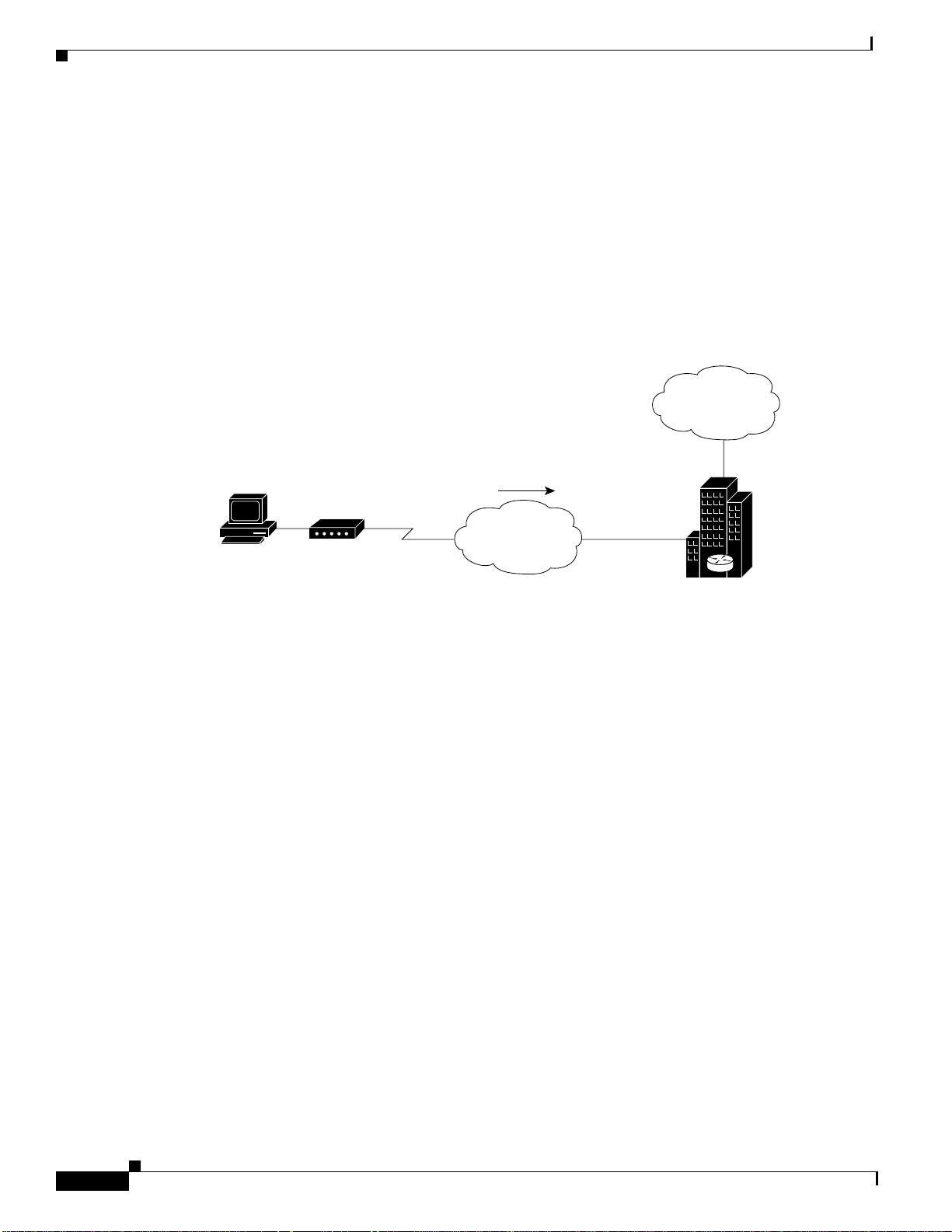
ISPs can configure a single Cisco AS5200 access servers to receive analog calls from remote PCs
connected to modems, as shown in Figure 51. The point of presence (POP) at the ISP central site could
also be a Cisco 2511 access server connected to external modems.
Network Topology
Figure 51 shows a small-scale dial-in scenario using modems.
Figure 51 Remote PC Using an Analog Modem to Dial In to a Cisco AS5200 Access Server
C running Windows 95
nd accessing
he Internet
Analog calls
Telco and ISP Dial Scenarios and Configurations
Internet
Analog
modem
Standard telephone
network (POTS)
T1 PRI
Cisco AS5200
used to provide
Internet access
by an ISP
S6537
Running Configuration for ISDN PRI
The following example runs on the Cisco AS5200 access server, as shown in Figure 51, which enables
remote analog users to dial in:
!
version 11.2
service timestamps debug datetime msec
service timestamps log datetime msec
service password-encryption
no service udp-small-servers
no service tcp-small-servers
!
hostname NAS
!
aaa new-model
aaa authentication login console enable
aaa authentication login vty tacacs+
aaa authentication login dialin tacacs+
aaa authentication ppp default tacacs+
aaa authentication ppp dialin if-needed tacacs+
enable secret cisco
!
async-bootp dns-server 10.1.3.1 10.1.3.2
isdn switch-type primary-5ess
!
DNC-306
Cisco IOS Dial Services Configuration Guide: Network Services
Page 3

Telco and ISP Dial Scenarios andConfigurations
controller T1 0
framing esf
clock source line primary
linecode b8zs
pri-group timeslots 1-24
!
controller T1 1
framing esf
clock source line secondary
linecode b8zs
pri-group timeslots 1-24
!
interface Loopback0
ip address 10.1.2.254 255.255.255.0
!
interface Ethernet0
ip address 10.1.1.10 255.255.255.0
ip summary address eigrp 10 10.1.2.0 255.255.255.0
!
interface Serial0
no ip address
shutdown
!
interface Serial1
no ip address
shutdown
!
interface Serial0:23
no ip address
encapsulation ppp
isdn incoming-voice modem
!
interface Serial1:23
no ip address
isdn incoming-voice modem
!
interface Group-Async1
ip unnumbered Loopback0
encapsulation ppp
async mode interactive
peer default ip address pool dialin_pool
no cdp enable
ppp authentication chap pap dialin
group-range 1 48
!
router eigrp 10
network 10.0.0.0
passive-interface Dialer0
no auto-summary
!
ip local pool dialin_pool 10.1.2.1 10.1.2.50
ip default-gateway 10.1.1.1
ip classless
!
dialer-list 1 protocol ip permit
!
line con 0
login authentication console
line 1 48
autoselect ppp
autoselect during-login
login authentication dialin
modem DialIn
!
Small- to Medium-Scale POPs
Cisco IOS Dial Services Configuration Guide: Network Services
DNC-307
Page 4

Small- to Medium-Scale POPs
line aux 0
login authentication console
line vty 0 4
login authentication vty
transport input telnet rlogin
!
end
Some service providers use a remote TACACS+ or RADIUS security serv er in this dial-in scenario. The
following example shows a TACACS+ entry that appears in the configuration file of a remote security
server:
user = PCuser1 {
}
Telco and ISP Dial Scenarios and Configurations
login = cleartext "dialpass1"
chap = cleartext "dialpass1"
service = ppp protocol = ip {
addr-pool = dialin_pool
}
service = exec {
autocmd = "ppp negotiate"
}
user = PCuser2 {
login = cleartext "dialpass2"
chap = cleartext "dialpass2"
service = ppp protocol = ip {
}
service = exec {
}
}
user = PCuser3 {
login = cleartext "dialpass3"
chap = cleartext "dialpass3"
service = ppp protocol = ip {
}
service = exec {
}
}
addr-pool = dialin_pool
autocmd = "ppp negotiate"
addr-pool = dialin_pool
autocmd = "ppp negotiate"
Running Configuration for Robbed-Bit Signalling
The following example shows a single Cisco AS5200 access server configured to support remote client
PCs dialing in with analog modems over traditional T1 lines. Digital ISDN calls do not transmit across
these older types of channelized lines. The conf iguratio n assumes that the client can dial in and connect
to the router in either terminal emulation mode (text only) or PPP packet mode.
DNC-308
Note The following configuration works only for analog modem calls. It includes no serial
D-channel configuration (Serial 0:23 and Serial 1:23).
Cisco IOS Dial Services Configuration Guide: Network Services
Page 5

Telco and ISP Dial Scenarios andConfigurations
version 11.2
service timestamps debug datetime msec
service timestamps log datetime msec
service password-encryption
no service udp-small-servers
no service tcp-small-servers
!
hostname NAS
!
aaa new-model
aaa authentication login console enable
aaa authentication login vty tacacs+
aaa authentication login dialin tacacs+
aaa authentication ppp default tacacs+
aaa authentication ppp dialin if-needed tacacs+
enable secret cisco
!
async-bootp dns-server 10.1.3.1 10.1.3.2
isdn switch-type primary-5ess
!
controller T1 0
framing esf
clock source line primary
linecode b8zs
cas-group 0 timeslots 1-24 type e&m-fgb
!
controller T1 1
framing esf
clock source line secondary
linecode b8zs
cas-group 0 timeslots 1-24 type e&m-fgb
!
interface Loopback0
ip address 10.1.2.254 255.255.255.0
!
interface Ethernet0
ip address 10.1.1.10 255.255.255.0
ip summary address eigrp 10 10.1.2.0 255.255.255.0
!
interface Serial0
no ip address
shutdown
!
interface Serial1
no ip address
shutdown
!
!
interface Group-Async1
ip unnumbered Loopback0
encapsulation ppp
async mode interactive
peer default ip address pool dialin_pool
no cdp enable
ppp authentication chap pap dialin
group-range 1 48
!
router eigrp 10
network 10.0.0.0
passive-interface Dialer0
no auto-summary
!
ip local pool dialin_pool 10.1.2.1 10.1.2.50
ip default-gateway 10.1.1.1
Small- to Medium-Scale POPs
Cisco IOS Dial Services Configuration Guide: Network Services
DNC-309
Page 6
Small- to Medium-Scale POPs
by an ISP
H
P
ip classless
!
dialer-list 1 protocol ip permit
!
line con 0
login authentication console
line 1 48
autoselect ppp
autoselect during-login
login authentication dialin
modem DialIn
line aux 0
login authentication console
line vty 0 4
login authentication vty
transport input telnet rlogin
!
end
Individual PCs Using ISDN Terminal Adapters
Telco and ISP Dial Scenarios and Configurations
Network Topology
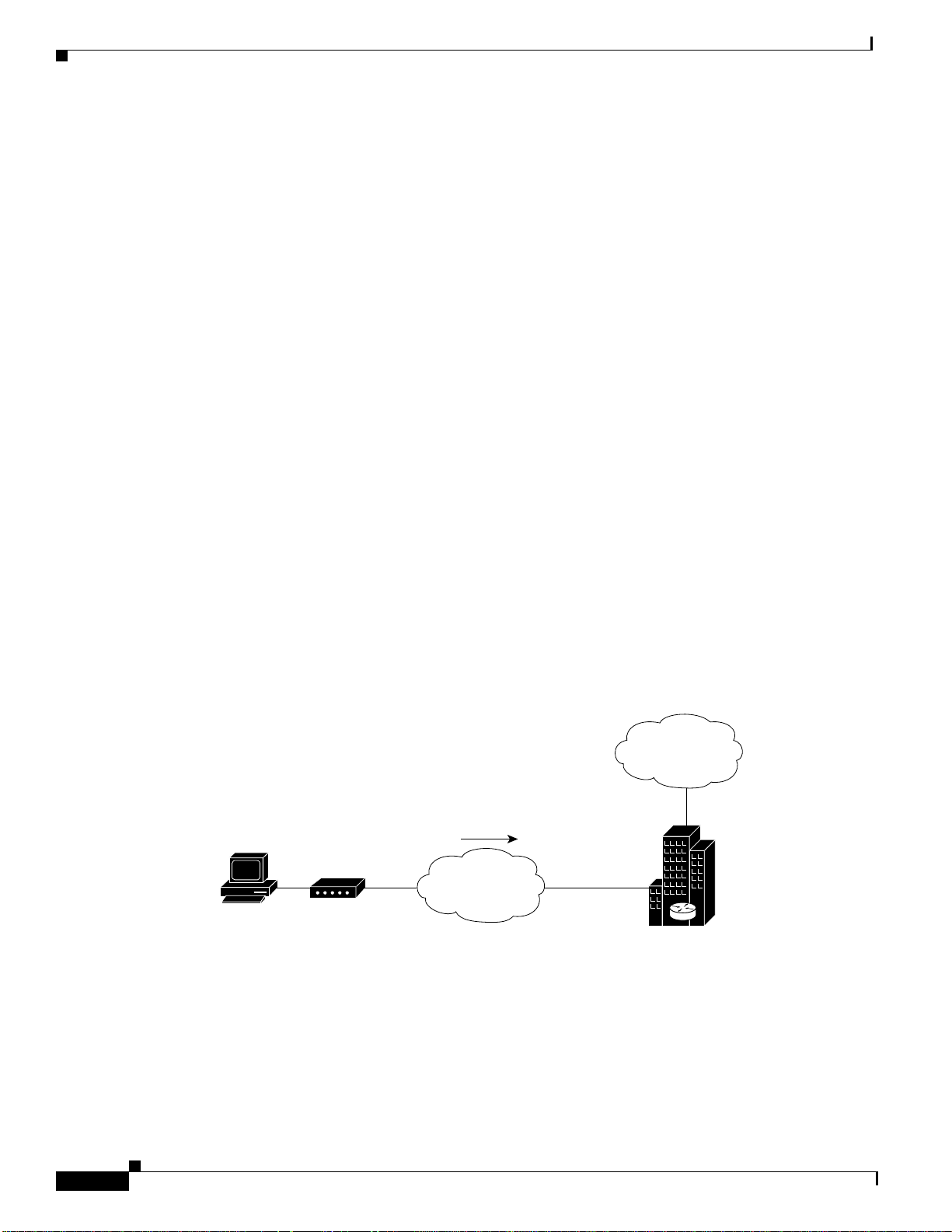
ISPs can configure a single Cisco AS5200 access server to receive digital multilink calls from remote
PCs connected to terminal adapters, as shown in Figure 52. The POP at the central site of the ISP can be
any Cisco router that supports ISDN PRI, such as the Cisco 4700-M router loaded with a channelized
T1 PRI network module.
Figure 52 shows a small-scale dial-in scenario using terminal adapters.
Figure 52 Remote PC Using a Terminal Adapter to Dial In to a Cisco AS5200 Access Server
Internet
ome office remote
C running Windows 95
BRI
Terminal
adapter
Digital calls
ISDN network
T1 PRI
Cisco AS5200
used to provide
Internet access
S6536
T o confi gure one Cisco AS5200 to accept both incoming ISDN and analog calls from indi vidual terminal
adapters and modems, see the section “Mixture of ISDN and Analog Modem Calls” later in this chapter.
Cisco IOS Dial Services Configuration Guide: Network Services
DNC-310
Page 7

Telco and ISP Dial Scenarios andConfigurations
Terminal Adapter Configuration Example
The following example configures a Cisco AS5200 access server to enable PCs fitted with internal or
external terminal adapters to dial in to an IP network. The terminal adapter configuration is set up for
asynchronous to synchronous PPP conversion. In some cases, PPP authentication must be set up for the
Password Authentication Protocol (PAP). Some terminal adapters only support PAP authentication.
!
version 11.2
service timestamps debug datetime msec
service timestamps log datetime msec
service password-encryption
no service udp-small-servers
no service tcp-small-servers
!
hostname NAS
!
aaa new-model
aaa authentication login console enable
aaa authentication login vty tacacs+
aaa authentication login dialin tacacs+
aaa authentication ppp default tacacs+
aaa authentication ppp dialin if-needed tacacs+
enable secret cisco
!
async-bootp dns-server 10.1.3.1 10.1.3.2
isdn switch-type primary-5ess
!
controller T1 0
framing esf
clock source line primary
linecode b8zs
pri-group timeslots 1-24
!
controller T1 1
framing esf
clock source line secondary
linecode b8zs
pri-group timeslots 1-24
!
interface Loopback0
ip address 10.1.2.254 255.255.255.0
!
interface Ethernet0
ip address 10.1.1.10 255.255.255.0
ip summary address eigrp 10 10.1.2.0 255.255.255.0
!
interface Serial0
no ip address
shutdown
!
interface Serial1
no ip address
shutdown
!
interface Serial0:23
no ip address
encapsulation ppp
dialer rotary-group 0
dialer-group 1
no fair-queue
no cdp enable
!
Small- to Medium-Scale POPs
Cisco IOS Dial Services Configuration Guide: Network Services
DNC-311
Page 8

Small- to Medium-Scale POPs
interface Serial1:23
no ip address
encapsulation ppp
dialer rotary-group 0
dialer-group 1
no fair-queue
no cdp enable
!
interface Dialer0
ip unnumbered Loopback0
no ip mroute-cache
encapsulation ppp
peer default ip address pool dialin_pool
dialer in-band
dialer-group 1
no fair-queue
no cdp enable
ppp authentication chap pap dialin
ppp multilink
!
router eigrp 10
network 10.0.0.0
passive-interface Dialer0
no auto-summary
!
ip local pool dialin_pool 10.1.2.1 10.1.2.50
ip default-gateway 10.1.1.1
ip classless
!
!
!
dialer-list 1 protocol ip permit
!
line con 0
login authentication console
line 1 48
autoselect ppp
autoselect during-login
login authentication dialin
modem DialIn
line aux 0
login authentication console
line vty 0 4
login authentication vty
transport input telnet rlogin
!
end
Telco and ISP Dial Scenarios and Configurations
DNC-312
Cisco IOS Dial Services Configuration Guide: Network Services
Page 9

Telco and ISP Dial Scenarios andConfigurations
H
r
a
m
the Internet
Home office PC
r
a
c
Mixture of ISDN and Analog Modem Calls
ISPs can configure a single Cisco AS5200 access server to receive calls from a mixture of remote PCs
connected to terminal adapters and modems, as shown in Figure 53.
Figure 53 Remote PCs Making Digital Calls and Analog Calls to a Cisco AS5200
unning Windows 95
nd making digital
alls in to the Internet
Terminal
adapter
BRI
Small- to Medium-Scale POPs
ISDN
Analog
Modem
ome office PC
unning Windows 95
nd making analog
odem calls in to
T1 PRI
ISP using a
Cisco AS5200
to provide
Internet access
Combination of Modem and ISDN Dial-In Configuration Example
The following example shows a combination of the modem and ISDN dial-in configurations. Using the
bearer capability information element in the call setup packet, the incoming calls are labeled as data or
voice. After the calls enter the access server, they are routed either to the serial configuration or to the
modems and group asynchronous configuration.
Internet
S6535
Cisco IOS Dial Services Configuration Guide: Network Services
DNC-313
Page 10

Small- to Medium-Scale POPs
Note This configuration assumes that only individual remote PCs are dialing in; no remote
routers are dialing in. For a remote router dial-in configuration, see the chapter “Enterprise
Dial Scenarios and Configurations” in this publication.
!
version 11.2
service timestamps debug datetime msec
service timestamps log datetime msec
service password-encryption
no service udp-small-servers
no service tcp-small-servers
!
hostname NAS
!
aaa new-model
aaa authentication login console enable
aaa authentication login vty tacacs+
aaa authentication login dialin tacacs+
aaa authentication ppp default tacacs+
aaa authentication ppp dialin if-needed tacacs+
enable secret cisco
!
async-bootp dns-server 10.1.3.1 10.1.3.2
isdn switch-type primary-5ess
!
controller T1 0
framing esf
clock source line primary
linecode b8zs
pri-group timeslots 1-24
!
controller T1 1
framing esf
clock source line secondary
linecode b8zs
pri-group timeslots 1-24
!
interface Loopback0
ip address 10.1.2.254 255.255.255.0
!
interface Ethernet0
ip address 10.1.1.10 255.255.255.0
ip summary address eigrp 10 10.1.2.0 255.255.255.0
!
interface Serial0
no ip address
shutdown
!
interface Serial1
no ip address
shutdown
!
interface Serial0:23
no ip address
encapsulation ppp
isdn incoming-voice modem
dialer rotary-group 0
dialer-group 1
no fair-queue
no cdp enable
!
Telco and ISP Dial Scenarios and Configurations
DNC-314
Cisco IOS Dial Services Configuration Guide: Network Services
Page 11

Telco and ISP Dial Scenarios andConfigurations
interface Serial1:23
no ip address
encapsulation ppp
isdn incoming-voice modem
dialer rotary-group 0
dialer-group 1
no fair-queue
no cdp enable
!
interface Group-Async1
ip unnumbered Loopback0
encapsulation ppp
async mode interactive
peer default ip address pool dialin_pool
no cdp enable
ppp authentication chap pap dialin
group-range 1 48
!
interface Dialer0
ip unnumbered Loopback0
no ip mroute-cache
encapsulation ppp
peer default ip address pool dialin_pool
dialer in-band
dialer-group 1
no fair-queue
no cdp enable
ppp authentication chap pap dialin
ppp multilink
!
router eigrp 10
network 10.0.0.0
passive-interface Dialer0
no auto-summary
!
ip local pool dialin_pool 10.1.2.1 10.1.2.50
ip default-gateway 10.1.1.1
ip classless
!
dialer-list 1 protocol ip permit
!
line con 0
login authentication console
line 1 48
autoselect ppp
autoselect during-login
login authentication dialin
modem DialIn
line aux 0
login authentication console
line vty 0 4
login authentication vty
transport input telnet rlogin
end
Small- to Medium-Scale POPs
Cisco IOS Dial Services Configuration Guide: Network Services
DNC-315
Page 12

Large-Scale POPs
Large-Scale POPs
This section describes how to set up a stack of access servers for a large-scale dial solution in the
following sections:
• Scaling Considerations
• How Stacking Works
• Stack Group of Access Servers Using MMP with an Offload Processor Examples
Scaling Considerations
Because of the significant increase in demand for Internet access, large POPs are required by many
Telcos and ISPs. Internet access configurations can be set up to enable users dialing in with individual
computers to make mixed ISDN multilink or modem connections using a stack of Cisco AS5200
universal access servers running Multichassis Multilink PPP (MMP).
You must consider scalability and call density issues when designing a lar ge-scale dial-in POP. Because
access servers have physical limitatio ns, such as how many dial-i n users can be supported on one de vice,
you should consider the conditions and recommendations described in Table 24.
Telco and ISP Dial Scenarios and Configurations
Table 24 Recommended Configurations for Different Remote Access Needs
Dial-in Demand You Need to Support Recommended Configuration
PCs dialing in, 75 to 90 percent modem calls,
10 to 25 percent ISDN calls (terminal
adapters or routers), and support for fewer
than 96 (T1) to 116 (E1) simultaneous dial-in
connections.
PCs dialing in, less than 50 percent modem
calls, more than 50 percent ISDN calls
(terminal adapters or routers), dial-in only,
and 250 or more simultaneous links into the
offload server.
Note Depending on the size of your POP requirement, you can replace th e Cisco AS5200 access
server with a Cisco AS5300, Cisco AS5800, or Cisco AccessPath. This hardware e xchange
provides higher call density performance and increases the number of ISDN PRI ports,
channelized ports, and modem ports on each chassis.
T wo Cisco AS5200 access servers configu red
for IP, basic security, MMP, L2F, and no
offload server.
Three or more Cisco AS5200 access servers
configured for IP, remote security, MMP, and
L2F. Each Cisco AS5200 access s erver is
configured to offload its segmentation and
reassembly of the multilink sessions onto an
offload server, such as a Cisco 7202 or
Cisco 4700 router.
DNC-316
Cisco IOS Dial Services Configuration Guide: Network Services
Page 13

Telco and ISP Dial Scenarios andConfigurations
How Stacking Works
Before you install and configure a stack of access servers, you should understand the basic concepts
described in the following sections, and how they work together in a large-scale dial-in solution:
• A Ty pical Multilink PPP Session
• Using Multichassis Multilink PPP
• Setting Up an Offload Server
• Using the Stack Group Bidding Protocol
• Using L2F
A Typical Multilink PPP Session
A basic multilink session is an ISDN connection between tw o routing dev ices, such as a Cisco 766 router
and a Cisco AS5200 access server. Figure 54 shows a remote PC connecting to a Cisco 766 ISDN router,
which in turn opens two B-channel connections at 128 kbps across an ISDN network. The Multilink PPP
(MLP) session is brought up. The Cisco 766 router sends four packets across the network to the
Cisco AS5200, which in turn reassembles the packets back into the correct order and sends them out the
LAN port to the Internet.
Large-Scale POPs
Figure 54 A Typical Multilink PPP Session
Dial-in session #1
PC running
Windows 95
Cisco 766
Using Multichassis Multilink PPP
The dial solution becomes more complex when the scenario is scaled to include mul tiple multili nk calls
connecting across multiple chassis. Figure 55 shows a terminal adapter making a call in to the
Cisco AS5200, labeled #1. Howe ver, only one of the access server’s 48 B channels is available to accept
the call. The other channels are busy with calls. As a result, one of the terminal adapter’s tw o B channels
is redirected to device #2. At this point, a multilink multichassis session is shared between two
Cisco AS5200s that belong to the same stack group. Packet fragments A and C go to device #1. Packet
fragments B and D go to device #2.
4
ISDN network
Service provider network
Hunt
group
555-1001
3
2
1
4
Cisco AS5200
2
3
1
Internet access
S6752
Cisco IOS Dial Services Configuration Guide: Network Services
DNC-317
Page 14

Large-Scale POPs
D
Telco and ISP Dial Scenarios and Configurations
Because device #1 is the first access server to receive a packet and establish a link, this access server
creates a virtual interface and becomes the bundle master. The bundle master takes ownership of the
MLP session with the remote device. The Multichassis Multilink PPP (MMP) protocol forwards the
second link from device #2 to the bundlemaster, which in turn bundles the two B channels together and
provides 128 kbps to the end user. Layer 2 Forwarding (L2F) is the mechanism that device #2 uses to
forward all packet fragments received from the terminal adapter to device #1. In this way , all packets and
calls virtually appear to terminate at device #1.
Figure 55 A Stack Group of Access Servers Using MMP Without an Offload Processor
Stack of two Cisco AS5200 access servers
used in one service provider network
Hunt
group
555-1001
ial-in session #2
PC
Terminal
adapter
ISDN network
C
D
Analog network
#1
A
#2
C
D B
Remote security
server
A
B
Internet
Modem
PC
access
S6751
Setting Up an Offload Server
Because MMP is a processor-intensive application, you might need to offload the processing or
segmentation and reassembly from the Cisco AS5200 access serv ers to a router with a higher CPU, such
as the Cisco 4700-M or Cisco 7206. We recommend that you include an offload server for dial-in
solutions that support more than 50 percent ISDN calls or more than ten multilink sessions per
Cisco AS5200 access server. (Refer to Figure 56.)
DNC-318
Cisco IOS Dial Services Configuration Guide: Network Services
Page 15

Telco and ISP Dial Scenarios andConfigurations
PC
D
Dial-in session #1
Figure 56 A Stack Group of Access Servers Using MMP with an Offload Processor
PC running
Windows 95
Stack of three Cisco AS5200 access servers
used in one service provider network
Hunt
group
555-1001
#1
1
4
3 2 1
#2
D
A
#3
B
C B
Cisco 7206 used for
offload processing
and has a rigged bid
for each call
Remote security
server
Using L2F, all packets
are encapsulated and
forwarded to the Cisco 7206
A
for reassembly of the multilink
and single link process
HSSI
ial-in session #2
Terminal
PC
adapter
Cisco 766
Modem
ISDN network
Analog network
3
4
2
C
D
Large-Scale POPs
Internet
access
S6486
Using the Stack Group Bidding Protocol
The Stack Group Bidding Protocol (SGBP) is a critical component used in multichassis multilink
sessions. The SGBP unites each Cisco AS5200 access server in a virtual stack, which enables the access
servers to become virtually tied together. Each independent stack member communicates with the other
members and determines which device CPU should be in charge of running the multilink session and
packet reassembly—the duty of the bundle master. The goal of SGBP is to find a common place to
forward the links and ensure that this destination has enough CPU to perform the segmentation and
packet reassembly. (Refer to Figure 56.)
When SGBP in configured on each Cisco AS5200, each access server sends out a query to each stack
group member stating, for example, “I have a call coming in from walt@options.com. What is your bid
for this user?” Each access server then consults the following default bidding criteria and answers the
query accordingly:
• Do I have an existing call or link for the user walt@options.com? If I do, then bid very high to get
this second link in to me.
• If I do not have an existing call for walt@options.com, then bid a value that is proportional to how
much CPU I have available.
• How busy am I supporting other users?
Cisco IOS Dial Services Configuration Guide: Network Services
DNC-319
Page 16

Telco and ISP Dial Scenarios and Configurations
Large-Scale POPs
Note An offload server will always serve as the bund lemaster b y bidding a higher value than the
other devices.
Using L2F
L2F is a critical component used in multichassis multilink sessions. If an access server is not in charge
of a multilink session, the access server encapsulates the fragmented PPP frames and forwards them to
the bundlemaster using L2F. The master device receives the calls, not through the dial port (such as a
dual T1/PRI card), but through the LAN or Ethernet port. L2F simply tunnels packet fragments to the
device that owns the multilink session for the call. If you include an offload server in your dial-in
scenario, it creates all the virtual interfaces, owns all the multilink sessions, and reassembles all the
fragmented packets received by L2F via the other stackgroup members. (Refer to Figure 56.)
Stack Group of Access Servers Using MMP with an Offload Processor Examples
The following sections provide examples for the devices shown in Figure 56:
• Cisco AS5200 Access Server #1
• Cisco AS5200 Access Server #2
• Cisco AS5200 Access Server #3
• Cisco 7206 as Offload Server
• RADIUS Remote Security Examples
Note Be sure to include your own IP addresses, host names, and security passwords
where appropriate.
Cisco AS5200 Access Server #1
The following example runs on the Cisco AS5200 access server labeled #1 in Figure 56:
!
version 11.2
service timestamps debug datetime msec
service timestamps log datetime msec
service password-encryption
no service udp-small-servers
no service tcp-small-servers
!
hostname AS5200-1
!
aaa new-model
aaa authentication login default local
aaa authentication login console enable
aaa authentication login vty local
aaa authentication login dialin radius
aaa authentication ppp default local
aaa authentication ppp dialin if-needed radius
aaa authorization exec local radius
aaa authorization network radius
DNC-320
Cisco IOS Dial Services Configuration Guide: Network Services
Page 17

Telco and ISP Dial Scenarios andConfigurations
aaa accounting network start-stop radius
aaa accounting exec start-stop radius
enable secret cisco
!
username admin password cisco
username MYSTACK password STACK-SECRET
sgbp group MYSTACK
sgbp member AS5200-2 10.1.1.12
sgbp member AS5200-3 10.1.1.13
sgbp member 7200 10.1.1.14
async-bootp dns-server 10.1.3.1 10.1.3.2
isdn switch-type primary-5ess
!
controller T1 0
framing esf
clock source line primary
linecode b8zs
pri-group timeslots 1-24
!
controller T1 1
framing esf
clock source line secondary
linecode b8zs
pri-group timeslots 1-24
!
interface Loopback0
ip address 10.1.2.62 255.255.255.192
!
interface Ethernet0
ip address 10.1.1.11 255.255.255.0
ip summary address eigrp 10 10.1.2.0 255.255.255.192
!
interface Serial0
no ip address
shutdown
!
interface Serial1
no ip address
shutdown
!
interface Serial0:23
no ip address
encapsulation ppp
isdn incoming-voice modem
dialer rotary-group 0
dialer-group 1
no fair-queue
no cdp enable
!
interface Serial1:23
no ip address
encapsulation ppp
isdn incoming-voice modem
dialer rotary-group 0
dialer-group 1
no fair-queue
no cdp enable
!
interface Group-Async1
ip unnumbered Loopback0
encapsulation ppp
async mode interactive
peer default ip address pool dialin_pool
no cdp enable
Large-Scale POPs
Cisco IOS Dial Services Configuration Guide: Network Services
DNC-321
Page 18

Large-Scale POPs
Telco and ISP Dial Scenarios and Configurations
ppp authentication chap pap dialin
group-range 1 48
!
interface Dialer0
ip unnumbered Loopback0
no ip mroute-cache
encapsulation ppp
peer default ip address pool dialin_pool
dialer in-band
dialer-group 1
no fair-queue
no cdp enable
ppp authentication chap pap dialin
ppp multilink
!
router eigrp 10
network 10.0.0.0
passive-interface Dialer0
no auto-summary
!
ip local pool dialin_pool 10.1.2.1 10.1.2.50
ip default-gateway 10.1.1.1
ip classless
!
!
!
dialer-list 1 protocol ip permit
radius-server host 10.1.1.23 auth-port 1645 acct-port 1646
radius-server host 10.1.1.24 auth-port 1645 acct-port 1646
radius-server key cisco
!
line con 0
login authentication console
line 1 48
autoselect ppp
autoselect during-login
login authentication dialin
modem DialIn
line aux 0
login authentication console
line vty 0 4
login authentication vty
transport input telnet rlogin
!
end
DNC-322
Cisco IOS Dial Services Configuration Guide: Network Services
Page 19

Telco and ISP Dial Scenarios andConfigurations
Cisco AS5200 Access Server #2
The following example runs on the Cisco AS5200 access server labeled #2 shown in Figure 56:
!
version 11.2
service timestamps debug datetime msec
service timestamps log datetime msec
service password-encryption
no service udp-small-servers
no service tcp-small-servers
!
hostname AS5200-2
!
aaa new-model
aaa authentication login default local
aaa authentication login console enable
aaa authentication login vty local
aaa authentication login dialin radius
aaa authentication ppp default local
aaa authentication ppp dialin if-needed radius
aaa authorization exec local radius
aaa authorization network radius
aaa accounting network start-stop radius
aaa accounting exec start-stop radius
enable secret cisco
!
username admin password cisco
username MYSTACK password STACK-SECRET
sgbp group MYSTACK
sgbp member AS5200-1 10.1.1.11
sgbp member AS5200-3 10.1.1.13
sgbp member 7200 10.1.1.14
async-bootp dns-server 10.1.3.1 10.1.3.2
isdn switch-type primary-5ess
!
controller T1 0
framing esf
clock source line primary
linecode b8zs
pri-group timeslots 1-24
!
controller T1 1
framing esf
clock source line secondary
linecode b8zs
pri-group timeslots 1-24
!
interface Loopback0
ip address 10.1.2.126 255.255.255.192
!
interface Ethernet0
ip address 10.1.1.12 255.255.255.0
ip summary address eigrp 10 10.1.2.64 255.255.255.192
!
interface Serial0
no ip address
shutdown
!
interface Serial1
no ip address
shutdown
!
Large-Scale POPs
Cisco IOS Dial Services Configuration Guide: Network Services
DNC-323
Page 20

Large-Scale POPs
Telco and ISP Dial Scenarios and Configurations
interface Serial0:23
no ip address
encapsulation ppp
isdn incoming-voice modem
dialer rotary-group 0
dialer-group 1
no fair-queue
no cdp enable
!
interface Serial1:23
no ip address
encapsulation ppp
isdn incoming-voice modem
dialer rotary-group 0
dialer-group 1
no fair-queue
no cdp enable
!
interface Group-Async1
ip unnumbered Loopback0
encapsulation ppp
async mode interactive
peer default ip address pool dialin_pool
no cdp enable
ppp authentication chap pap dialin
group-range 1 48
!
interface Dialer0
ip unnumbered Loopback0
no ip mroute-cache
encapsulation ppp
peer default ip address pool dialin_pool
dialer in-band
dialer-group 1
no fair-queue
no cdp enable
ppp authentication chap pap dialin
ppp multilink
!
router eigrp 10
network 10.0..0.0
passive-interface Dialer0
no auto-summary
!
ip local pool dialin_pool 10.1.2.65 10.1.2.114
ip default-gateway 10.1.1.1
ip classless
!
dialer-list 1 protocol ip permit
radius-server host 10.1.1.23 auth-port 1645 acct-port 1646
radius-server host 10.1.1.24 auth-port 1645 acct-port 1646
radius-server key cisco
!
line con 0
login authentication console
line 1 48
autoselect ppp
autoselect during-login
login authentication dialin
modem DialIn
line aux 0
login authentication console
line vty 0 4
login authentication vty
DNC-324
Cisco IOS Dial Services Configuration Guide: Network Services
Page 21

Telco and ISP Dial Scenarios andConfigurations
transport input telnet rlogin
!
end
Cisco AS5200 Access Server #3
The following example runs on the Cisco AS5200 access server labeled #3 in Figure 56:
!
version 11.2
service timestamps debug datetime msec
service timestamps log datetime msec
service password-encryption
no service udp-small-servers
no service tcp-small-servers
!
hostname AS5200-3
!
aaa new-model
aaa authentication login default local
aaa authentication login console enable
aaa authentication login vty local
aaa authentication login dialin radius
aaa authentication ppp default local
aaa authentication ppp dialin if-needed radius
aaa authorization exec local radius
aaa authorization network radius
aaa accounting network start-stop radius
aaa accounting exec start-stop radius
enable secret cisco
!
username admin password cisco
username MYSTACK password STACK-SECRET
sgbp group MYSTACK
sgbp member AS5200-1 10.1.1.11
sgbp member AS5200-2 10.1.1.12
sgbp member 7200 10.1.1.14
async-bootp dns-server 10.1.3.1 10.1.3.2
isdn switch-type primary-5ess
!
controller T1 0
framing esf
clock source line primary
linecode b8zs
pri-group timeslots 1-24
!
controller T1 1
framing esf
clock source line secondary
linecode b8zs
pri-group timeslots 1-24
!
interface Loopback0
ip address 10.1.2.190 255.255.255.192
!
interface Ethernet0
ip address 10.1.1.13 255.255.255.0
ip summary address eigrp 10 10.1.2.128 255.255.255.192
!
interface Serial0
no ip address
shutdown
!
Large-Scale POPs
Cisco IOS Dial Services Configuration Guide: Network Services
DNC-325
Page 22

Large-Scale POPs
Telco and ISP Dial Scenarios and Configurations
interface Serial1
no ip address
shutdown
!
interface Serial0:23
no ip address
encapsulation ppp
isdn incoming-voice modem
dialer rotary-group 0
dialer-group 1
no fair-queue
no cdp enable
!
interface Serial1:23
no ip address
encapsulation ppp
isdn incoming-voice modem
dialer rotary-group 0
dialer-group 1
no fair-queue
no cdp enable
!
interface Group-Async1
ip unnumbered Loopback0
encapsulation ppp
async mode interactive
peer default ip address pool dialin_pool
no cdp enable
ppp authentication chap pap dialin
group-range 1 48
!
interface Dialer0
ip unnumbered Loopback0
no ip mroute-cache
encapsulation ppp
peer default ip address pool dialin_pool
dialer in-band
dialer-group 1
no fair-queue
no cdp enable
ppp authentication chap pap dialin
ppp multilink
!
router eigrp 10
network 10.0.0.0
passive-interface Dialer0
no auto-summary
!
ip local pool dialin_pool 10.1.2.129 10.1.2.178
ip default-gateway 10.1.1.1
ip classless
!
dialer-list 1 protocol ip permit
radius-server host 10.1.1.23 auth-port 1645 acct-port 1646
radius-server host 10.1.1.24 auth-port 1645 acct-port 1646
radius-server key cisco
!
line con 0
login authentication console
line 1 48
autoselect ppp
autoselect during-login
login authentication dialin
modem DialIn
DNC-326
Cisco IOS Dial Services Configuration Guide: Network Services
Page 23

Telco and ISP Dial Scenarios andConfigurations
line aux 0
login authentication console
line vty 0 4
login authentication vty
transport input telnet rlogin
!
end
Cisco 7206 as Offload Server
The following example runs on the Cisco 7206 router shown in Figure 56:
Note Any Cisco router that has a strong CPU can be used as an offload server, such as a
Cisco 4500-M, 4700-M, or 3640. However, the router must be configured to handle the
necessary processing overhead demanded by each stack member.
!
version 11.2
service timestamps debug datetime msec
service timestamps log datetime msec
service password-encryption
no service udp-small-servers
no service tcp-small-servers
!
hostname 7200
!
aaa new-model
aaa authentication login default local
aaa authentication login console enable
aaa authentication login vty local
aaa authentication login dialin radius
aaa authentication ppp default local
aaa authentication ppp dialin if-needed radius
aaa authorization exec local radius
aaa authorization network radius
aaa accounting network start-stop radius
aaa accounting exec start-stop radius
enable secret cisco
!
username MYSTACK password STACK-SECRET
username admin password cisco
multilink virtual-template 1
sgbp group MYSTACK
sgbp member AS5200-1 10.1.1.11
sgbp member AS5200-2 10.1.1.12
sgbp member AS5200-3 10.1.1.13
sgbp seed-bid offload
async-bootp dns-server 10.1.3.1 10.1.3.2
!
interface Loopback0
ip address 10.1.2.254 255.255.255.192
!
interface Ethernet2/0
ip address 10.1.1.14 255.255.255.0
ip summary address eigrp 10 10.1.2.192 255.255.255.192
!
interface Ethernet2/1
no ip address
shutdown
!
Large-Scale POPs
Cisco IOS Dial Services Configuration Guide: Network Services
DNC-327
Page 24

Large-Scale POPs
Telco and ISP Dial Scenarios and Configurations
interface Ethernet2/2
no ip address
shutdown
!
interface Ethernet2/3
no ip address
shutdown
!
interface Virtual-Template1
ip unnumbered Loopback0
no ip mroute-cache
peer default ip address pool dialin_pool
ppp authentication chap pap dialin
ppp multilink
!
router eigrp 10
network 10.0.0.0
passive-interface Virtual-Template1
no auto-summary
!
ip local pool dialin_pool 10.1.2.193 10.1.2.242
ip default-gateway 10.1.1.1
ip classless
!
radius-server host 10.1.1.23 auth-port 1645 acct-port 1646
radius-server host 10.1.1.24 auth-port 1645 acct-port 1646
radius-server key cisco
!
line con 0
login authentication console
line aux 0
login authentication console
line vty 0 4
login authentication vty
!
end
RADIUS Remote Security Examples
The RADIUS examples in the followi ng sections use the Inte rnet Engine ering Task Force (IETF) syntax
for the attributes:
• User Setup for PPP
• User Setup for PPP and Static IP Address
• Enabling Router Dial-In
• User Setup for SLIP
• User Setup for SLIP and Static IP Address
• Telnetting to a UNIX Host
• Automatic Rlogin to UNIX Host
Depending on how the dictionary is set up, the syntax for these configurations might differ between
versions of RADIUS daemons.
Note Y ou must hav e the async dynamic address command enabled on the netwo rk access server
if you use Framed-IP-Address to statically assign IP addresses.
Cisco IOS Dial Services Configuration Guide: Network Services
DNC-328
Page 25

Telco and ISP Dial Scenarios andConfigurations
User Setup for PPP
The following example shows a user setup for PPP. The user’s IP address comes from the configured
default IP address that is set up on the interface (which could be a specific default IP address, a pointer
to a local pool of addresses, or a pointer to a Dynamic Host Conf iguration Protocol (DHCP) serv er). The
special address that signals the default address is 255.255.255.25 4.
pppme Password = "cisco"
CHAP-Password = "cisco"
Service-Type = Framed,
Framed-Protocol = PPP,
Framed-IP-Address = 255.255.255.254
User Setup for PPP and Static IP Address
The following example sho ws a user set up for PPP and a static IP address t hat stays wi th the user across
all connections. Make sure your router is set up to support this configuration, especially for large or
multiple POPs.
staticallypppme Password = "cisco"
CHAP-Password = "cisco"
Service-Type = Framed,
Framed-Protocol = PPP,
Framed-IP-Address = 1.1.1.1
Large-Scale POPs
Enabling Router Dial-In
The following example supports a router dialing in, which requires that a static IP address and a remote
Ethernet interface be added to the network access server’s routing table. The router’s WAN port is
assigned the address 1.1.1.2. The remote Ethernet interface is 2.1.1.0 with a class C mask. Be sure your
routing table can support this requirement. You might need to redistrib ute the static route with a dynamic
routing protocol.
routeme Password = "cisco"
CHAP-Password = "cisco"
Service-Type = Framed,
Framed-Protocol = PPP,
Framed-IP-Address = 1.1.1.1
Framed-Route = "2.1.1.0/24 1.1.1.2"
User Setup for SLIP
The following example shows a user setup for SLIP. Remote users are assigned to the default address on
the interface.
slipme Password = "cisco"
Service-Type = Framed,
Framed-Protocol = SLIP,
Framed-IP-Address = 255.255.255.254
Cisco IOS Dial Services Configuration Guide: Network Services
DNC-329
Page 26

PPP Calls over X.25 Networks
User Setup for SLIP and Static IP Address
The following example shows a user setup for SLIP and a static IP address that stays with the user across
all connections. Make sure your routing is set up to support this configuration, especially for large or
multiple POPs.
staticallyslipme Password = "cisco"
Service-Type = Framed,
Framed-Protocol = SLIP,
Framed-IP-Address = 1.1.1.13
Telnetting to a UNIX Host
The following example au tomatically uses Telnet to connect the user to a UNIX host. This configuration
is useful for registering new users, providing basic UNIX shell services, or providing a guest account.
telnetme Password = "cisco"
Service-Type = Login,
Login-Service = Telnet,
Login-IP-Host = 4.1.1.1
Telco and ISP Dial Scenarios and Configurations
Automatic Rlogin to UNIX Host
The following example automatically uses rlogin to connect the user to a UNIX host:
rloginme Password = "cisco"
Service-Type = Login,
Login-Service = Rlogin,
Login-IP-Host =4.1.1.2
If you want to prevent a second password prompt from being brought up, you must have the following
two commands enabled on the router or access server:
• rlogin trusted-remoteuser-source local
• rlogin trusted-localuser-source radius
PPP Calls over X.25 Networks
Remote PCs stationed in X.25 packet assembler-disassembler (PAD ) networks can access the Internet
by dialing in to Cisco routers, which support PPP. By positioning a Cisco router at the corner of an X.25
network, ISPs and telcos can provide Internet and PPP access to PAD users. All remote PAD users that
dial in to X.25 networks dial in to one Cisco router that allows PPP connections. Although connection
performance is not optimal, these X.25 to PPP calls utilize installed bases of X.25 equipment and cost
less to operate than connecting over the standard telephone network.
DNC-330
Note This dial-in scenario can also be used as an enterprise solution. In this case, an enterprise
consults with a third-party service provider that al lows en terprises to le verage e xiting X.25
enterprise equipment to provide connections back into enterprise environments.
Cisco IOS Dial Services Configuration Guide: Network Services
Page 27

Telco and ISP Dial Scenarios andConfigurations
S6551
Overview
Many cities throughout the world have large installed bases of PCs interfacing with older modems,
PADs, and X.25 networks. These remote PCs or terminals dial in to PADs and make X.25 PAD calls or
terminal connections to mainframe computers or other devices, which run the X.25 protocol.
Unfortunately, the user interface is only a regular text-based screen in character mode (as opposed to
packet mode). Therefore, many ISPs and telcos that have large investments in X.25 networks are
upgrading their outdated equipment and creating separate networks for PPP connections. Because this
upgrade process takes substantial time and money to complete, using a Cisco router to allow PPP
connections over an X.25 network is a good interim solution for a dead-end dial case.
Remote PC Browsing Network Topology
Figure 57 shows a remote PC browsing the Internet through an X.25 PAD call and a Cisco 4500 router.
This X.25 network is owned by an ISP or telco that is heavily invested in X.25 equipment, currently
upgrading its outdated equipment, and creating separate networks for PPP connections. In this topology ,
the Cisco 4500 router performs protocol translation between the protocols X.25 and PPP. The router is
configured to accept an incoming X.25 PAD call, run and unpack PPP packets over the call, and enable
the remote PC to function as if it were on the IP network.
PPP Calls over X.25 Networks
Figure 57 Remote PC Browsing the Internet Through an X.25 PAD Call and a Cisco 4500 Router
PC running
Windows 95
and browsing
the Internet
Modem
Berlins PAD
Modem Modem
X.25
IP network
Eastern United
States
Warsaw PAD
X.25
Service provider
European X.25
network
X.25
Milan PAD
X.25
Cisco 4500
installed at
service provider
central site
Modems
Modems
For more information about configuring protocol translation, see the chapter “Configuring Protocol
Translation and Virtual Asynchronous Devices” in the Cisco IOS Dial Services Configuration Guide:
Terminal Services publication.
Cisco IOS Dial Services Configuration Guide: Network Services
DNC-331
Page 28

PPP Calls over X.25 Networks
Protocol Translation Configuration Example
In the following example, PAD callers that dial 4085551234 receive a router prompt. PAD callers that
dial 4085555123401 start PPP and pick up an address from the IP pool called dialin_pool. These
addresses are “borrowed” from the Ethernet interface on th e Cisco 4500 rout er . Addi tionally, a loopback
interface network can be created and the X.25 addresses can be set. Howev er , a routin g protocol must be
run to advertise the loopback interface network if this method is used.
Note Be sure to include your own IP addresses, host names, and security passwords
where appropriate in the following examples.
service timestamps debug datetime msec
service timestamps log datetime msec
service password-encryption
no service udp-small-servers
no service tcp-small-servers
!
hostname NAS
!
aaa new-model
aaa authentication login console enable
aaa authentication login vty tacacs+
aaa authentication login dialin tacacs+
aaa authentication ppp default tacacs+
aaa authentication ppp dialin if-needed tacacs+
enable secret cisco
!
async-bootp dns-server 10.1.3.1 10.1.3.2
!
vty-async
vty-async ppp authentication chap pap
!
interface Loopback0
ip address 10.1.2.254 255.255.255.0
!
interface Ethernet0
ip address 10.1.1.10 255.255.255.0
ip summary address eigrp 10 10.1.2.0 255.255.255.0
!
interface Serial0
no ip address
encapsulation x25
x25 address 4085551234
x25 accept-reverse
x25 default pad
!
router eigrp 10
network 10.0.0.0
passive-interface Dialer0
no auto-summary
!
ip local pool dialin_pool 10.1.2.1 10.1.2.50
ip default-gateway 10.1.1.1
!
ip classless
!
translate x25 4085555123401 ppp ip-pool scope-name dialin_pool
!
dialer-list 1 protocol ip permit
!
Telco and ISP Dial Scenarios and Configurations
DNC-332
Cisco IOS Dial Services Configuration Guide: Network Services
Page 29

Telco and ISP Dial Scenarios andConfigurations
line con 0
login authentication console
line aux 0
login authentication console
line vty 0 150
login authentication vty
transport input telnet rlogin
!
end
PPP Calls over X.25 Networks
Cisco IOS Dial Services Configuration Guide: Network Services
DNC-333
Page 30

PPP Calls over X.25 Networks
Telco and ISP Dial Scenarios and Configurations
DNC-334
Cisco IOS Dial Services Configuration Guide: Network Services
 Loading...