

Page 1

Cisco Aironet 1200 Series Access Point Software Configuration Guide
Software Release 12.03T
Corporate Headquarters
Cisco Systems, Inc.
170 West Tasman Drive
San Jose, CA 95134-1706
USA
http://www.cisco.com
Tel: 408 526-4000
800 553-NETS (6387)
Fax: 408 526-4100
Text Part Number: OL-2159-05
Page 2

THE SPECIFICATIONS AND INFORMATION REGARDING THE PRODUCTS IN THIS MANUAL ARE SUBJECT TO CHANGE WITHOUT NOTICE. ALL
STATEMENTS, INFORMATION, AND RECOMMENDATIONS IN THIS MANUAL ARE BELIEVED TO BE ACCURATE BUT ARE PRESENTED WITHOUT
WARRANTY OF ANY KIND, EXPRESS OR IMPLIED. USERS MUST TAKE FULL RESPONSIBILITY FOR THEIR APPLICATION OF ANY PRODUCTS.
THE SOFTWARE LICENSE AND LIMITED WARRANTY FOR THE ACCOMPANYING PRODUCT ARE SET FORTH IN THE INFORMATION PACKET THAT
SHIPPED WITH THE PRODUCT AND ARE INCORPORATED HEREIN BY THIS REFERENCE. IF YOU ARE UNABLE TO LOCATE THE SOFTWARE LICENSE
OR LIMITED WARRANTY, CONTACT YOUR CISCO REPRESENTATIVE FOR A COPY.
The Cisco implementation of TCP header compression is an adaptation of a program developed by the University of California, Berkeley (UCB) as part of UCB’s public
domain version of the UNIX operating system. All rights reserved. Copyright © 1981, Regents of the University of California.
NOTWITHSTANDING ANY OTHER WARRANTY HEREIN, ALL DOCUMENT FILES AND SOFTWARE OF THESE SUPPLIERS ARE PROVIDED “AS IS” WITH
ALL FAULTS. CISCO AND THE ABOVE-NAMED SUPPLIERS DISCLAIM ALL WARRANTIES, EXPRESSED OR IMPLIED, INCLUDING, WITHOUT
LIMITATION, THOSE OF MERCHANTABILITY, FITNESS FOR A PARTICULAR PURPOSE AND NONINFRINGEMENT OR ARISING FROM A COURSE OF
DEALING, USAGE, OR TRADE PRACTICE.
IN NO EVENT SHALL CISCO OR ITS SUPPLIERS BE LIABLE FOR ANY INDIRECT, SPECIAL, CONSEQUENTIAL, OR INCIDENTAL DAMAGES, INCLUDING,
WITHOUT LIMITATION, LOST PROFITS OR LOSS OR DAMAGE TO DATA ARISING OUT OF THE USE OR INABILITY TO USE THIS MANUAL, EVEN IF CISCO
OR ITS SUPPLIERS HAVE BEEN ADVISED OF THE POSSIBILITY OF SUCH DAMAGES.
CCIP, CCSP, the Cisco Arrow logo, the Cisco Powered Network mark, Cisco Unity, Follow Me Browsing, FormShare, and StackWise are trademarks of Cisco Systems, Inc.;
Changing the Way We Work, Live, Play, and Learn, and iQuick Study are service marks of Cisco Systems, Inc.; and Aironet, ASIST, BPX, Catalyst, CCDA, CCDP, CCIE, CCNA,
CCNP, Cisco, the Cisco Certified Internetwork Expert logo, Cisco IOS, the Cisco IOS logo, Cisco Press, Cisco Systems, Cisco Systems Capital, the Cisco Systems logo,
Empowering the Internet Generation, Enterprise/Solver, EtherChannel, EtherSwitch, Fast Step, GigaStack, Internet Quotient, IOS, IP/TV, iQ Expertise, the iQ logo, iQ Net
Readiness Scorecard, LightStream, MGX, MICA, the Networkers logo, Networking Academy, Network Registrar, Pack et , PIX, Post-Routing, Pre-Routing, RateMUX, Registrar,
ScriptShare, SlideCast, SMARTnet, StrataView Plus, Stratm, SwitchProbe, TeleRouter, The Fastest Way to Increase Your Internet Quotient, TransPath, and VCO are registered
trademarks of Cisco Systems, Inc. and/or its affiliates in the U.S. and certain other countries.
All other trademarks mentioned in this document or Web site are the property of their respective owners. The use of the word partner does not imply a partnership relationship
between Cisco and any other company. (0304R)
Cisco Aironet 1200 Series Access Point Software Configuration Guide
Copyright © 2001–2003, Cisco Systems, Inc.
All rights reserved.
Page 3

Preface xiii
Audience and Scope xiii
Organization xiii
Conventions xiv
Related Publications xv
Obtaining Documentation xv
Cisco.com xv
Documentation CD-ROM xvi
Ordering Documentation xvi
Documentation Feedback xvi
Obtaining Technical Assistance xvii
Cisco TAC Website xvii
Opening a TAC Case xvii
TAC Case Priority Definitions xvii
Obtaining Additional Publications and Information xviii
CONTENTS
CHAPTER
1 Overview 1-1
Key Features 1-2
Management Options 1-3
Roaming Client Devices 1-3
Quality of Service Support 1-3
What is QoS? 1-4
Limitations and Restrictions 1-4
Related Documents 1-4
VLAN Support 1-5
What is a VLAN? 1-5
Related Documents 1-6
Incorporating Wireless Devices into VLANs 1-6
Network Configuration Examples 1-8
Root Unit on a Wired LAN 1-8
Repeater Unit that Extends Wireless Range 1-9
Central Unit in an All-Wireless Network 1-10
A VLAN Example 1-7
OL-2159-01
Cisco Aironet 1200 Series Access Point Software Configuration Guide
iii
Page 4

Contents
CHAPTER
CHAPTER
2 Using the Management Interfaces 2-1
Using the Web-Browser Interface 2-2
Using the Web-Browser Interface for the First Time 2-2
Using the Management Pages in the Web-Browser Interface 2-2
Navigating Using the Map Windows 2-3
Using the Command-Line Interface 2-4
Preparing to Use a Terminal Emulator 2-4
Connecting the Serial Cable 2-5
Setting Up the Terminal Emulator 2-5
Changing Settings with the CLI 2-5
Selecting Pages and Settings 2-6
Applying Changes to the Configuration 2-7
Using a Telnet Session 2-7
Using SNMP 2-7
Supported MIBs 2-8
3 Radio Configuration and Basic Settings 3-1
Basic Settings 3-2
Entering Basic Settings 3-3
System Name 3-3
MAC Address 3-3
System Serial Number 3-3
Configuration Server Protocol 3-4
Default IP Address 3-4
Default IP Subnet Mask 3-4
Default Gateway 3-4
Radio Service Set ID (SSID) 3-4
Role in Radio Network 3-4
Radio Network Optimization (Optimize Radio Network For) 3-6
Security Setup Link 3-6
Radio Network Compatibility (Ensure Compatibility With) 3-7
Security Setup Link 3-7
SNMP Admin. Community 3-7
iv
Radio Configuration 3-7
Entering Identity Information 3-8
Settings on the AP Radio Identification Page 3-8
Entering Radio Hardware Information 3-10
Settings on the AP Radio Hardware Page 3-11
Entering Advanced Configuration Information 3-15
Cisco Aironet 1200 Series Access Point Software Configuration Guide
OL-2159-01
Page 5

Settings on the AP Radio Advanced Page 3-17
Ethernet Configuration 3-23
Entering Identity Information 3-23
Settings on the Ethernet Identification Page 3-24
Entering Ethernet Hardware Information 3-24
Settings on the Ethernet Hardware Page 3-25
Entering Advanced Configuration Information 3-27
Settings on the Ethernet Advanced Page 3-27
Contents
CHAPTER
4 Configuring VLANs 4-1
Entering VLAN Information 4-2
Settings on the VLAN Setup page 4-2
VLAN Summary Status Link 4-3
VLAN (802.1Q) Tagging 4-3
802.1Q Encapsulation Mode 4-3
Maximum Number of Enabled VLAN IDs 4-3
Native VLAN ID 4-3
Single VLAN ID which allows Unencrypted packets 4-4
Optionally allow Encrypted packets on the unencrypted VLAN 4-4
VLAN ID 4-4
VLAN Name 4-4
Existing VLANs 4-4
VLAN Security Policy 4-4
Broadcast Domain Segmentation 4-5
Native VLAN Configuration 4-5
Primary and Secondary SSIDs 4-6
RADIUS-Based VLAN Access Control 4-7
OL-2159-01
Criteria for Deploying Wireless VLANs 4-8
A Wireless VLAN Deployment Example 4-9
Using the Configuration Screens 4-11
Obtaining and Recording VLAN ID and Setup Information 4-11
Creating and Configuring VLANs on the Access Point 4-11
Creating the Native VLAN 4-11
Creating the Full- and Part-Time VLANs 4-14
Creating the Guest VLAN 4-15
Creating the Maintenance VLAN 4-15
Creating and Configuring the SSIDs 4-16
Enabling VLAN (802.1Q) Tagging and Identifying the Native VLAN 4-19
Creating an SSID for Infrastructure Devices 4-21
Cisco Aironet 1200 Series Access Point Software Configuration Guide
v
Page 6

Contents
Guidelines for Wireless VLAN Deployment 4-21
CHAPTER
5 Configuring Filters and QoS 5-1
Filter Setup 5-2
Protocol Filtering 5-2
Creating a Protocol Filter 5-3
Enabling a Protocol Filter 5-5
MAC Address Filtering 5-6
Creating a MAC Address Filter 5-7
QoS Configuration 5-10
Entering Information on the AP Radio Quality of Service Setup Page 5-10
Settings on the Quality of Service Setup Page 5-11
Generate QBSS Element 5-11
Use Symbol Extensions 5-11
Send IGMP General Query 5-12
Traffic Category 5-12
Applying QoS 5-12
By Station 5-12
By VLAN 5-14
By Filter 5-15
By CoS Value 5-16
By DSCP Value 5-16
CHAPTER
A Wireless QoS Deployment Example 5-17
WEP Set on the Wireless Phone 5-19
WEP Not Set on the Wireless Phone 5-19
6 Configuring Proxy Mobile IP 6-1
Proxy Mobile IP 6-2
Introduction to Mobility in IP 6-2
The Nomadic Approach 6-3
The Mobile Approach 6-3
Mobile IP Explained 6-3
Proxy Mobile IP Explained 6-5
Before Deploying Proxy Mobile IP 6-6
Issues to Consider While Deploying Proxy Mobile IP 6-7
Components of a Proxy Mobile IP Network 6-7
How Proxy Mobile IP Works 6-8
Agent Discovery 6-8
Subnet Map Exchange 6-9
vi
Cisco Aironet 1200 Series Access Point Software Configuration Guide
OL-2159-01
Page 7

Registration 6-10
Tunneling 6-10
Proxy Mobile IP Security 6-11
The Proxy Mobile IP Setup Page 6-11
General 6-12
Settings on the Proxy Mobile IP General Page 6-13
Authentication Server 6-13
Settings on the Authenticator Configuration Page 6-14
Local SA Bindings 6-15
Settings on the Local SA Bindings Page 6-15
Statistics 6-16
Settings on the Proxy Mobile IP Statistics Page 6-16
View Subnet Map Table 6-18
Settings on the Subnet Map Table Page 6-18
Configuring Proxy Mobile IP 6-18
Configuring Proxy Mobile IP on Your Wired LAN 6-19
Configuring Mobile IP Security Associations on a CiscoSecure ACS Server 6-23
Contents
CHAPTER
7 Configuring Other Settings 7-1
Server Setup 7-2
Entering Time Server Settings 7-2
Settings on the Time Server Setup Page 7-3
Entering Boot Server Settings 7-4
Settings on the Boot Server Setup Page 7-4
Entering Web Server Settings and Setting Up Access Point Help 7-7
Settings on the Web Server Setup Page 7-7
Entering Name Server Settings 7-9
Settings on the Name Server Setup Page 7-9
Entering FTP Settings 7-10
Settings on the FTP Setup Page 7-10
Routing Setup 7-11
Entering Routing Settings 7-12
Default Gateway 7-12
New Network Route Settings 7-12
Installed Network Routes list 7-13
Association Table Display Setup 7-13
Association Table Filters Page 7-13
Settings on the Association Table Filters Page 7-15
Association Table Advanced Page 7-16
OL-2159-01
Cisco Aironet 1200 Series Access Point Software Configuration Guide
vii
Page 8

Contents
Settings on the Association Table Advanced Page 7-17
Event Notification Setup 7-19
Event Display Setup Page 7-19
Settings on the Event Display Setup Page 7-19
Event Handling Setup Page 7-21
Settings on the Event Handling Setup Page 7-23
Event Notifications Setup Page 7-24
Settings on the Event Notifications Setup Page 7-25
Should Notify-Disposition Events generate SNMP Traps? 7-25
SNMP Trap Destination 7-25
SNMP Trap Community 7-25
Should Notify-Disposition Events generate Syslog Messages? 7-25
Should Syslog Messages use the Cisco EMBLEM Format? 7-26
Syslog Destination Address 7-26
Syslog Facility Number 7-26
IEEE SNMP Traps Should Generate the Following Notifications 7-26
CHAPTER
8 Security Setup 8-1
Security Overview 8-2
Levels of Security 8-2
Encrypting Radio Signals with WEP 8-2
Additional WEP Security Features 8-3
Network Authentication Types 8-3
Combining MAC-Based, EAP, and Open Authentication 8-6
Protecting the Access Point Configuration with User Manager 8-7
Setting Up WEP 8-7
Using SNMP to Set Up WEP 8-10
Enabling Additional WEP Security Features 8-10
Enabling Message Integrity Check (MIC) 8-10
Enabling Temporal Key Integrity Protocol (TKIP) 8-12
Enabling Broadcast WEP Key Rotation 8-13
Setting Up Open or Shared Key Authentication 8-14
Setting Up EAP Authentication 8-15
Enabling EAP on the Access Point 8-15
Enabling EAP in Cisco Secure ACS 8-18
Setting a Session-Based WEP Key Timeout 8-19
Setting Up a Repeater Access Point As a LEAP Client 8-19
viii
Setting Up MAC-Based Authentication 8-21
Enabling MAC-Based Authentication on the Access Point 8-21
Cisco Aironet 1200 Series Access Point Software Configuration Guide
OL-2159-01
Page 9

Authenticating Client Devices Using MAC Addresses or EAP 8-25
Enabling MAC-Based Authentication in Cisco Secure ACS 8-26
Summary of Settings for Authentication Types 8-27
RADIUS Attributes Sent by the Access Point 8-29
Setting Up Backup Authentication Servers 8-31
Setting Up Administrator Authorization 8-32
Creating a List of Authorized Management System Users 8-33
Setting up Centralized Administrator Authentication 8-35
System Flow Notes 8-37
Authorization Parameters 8-38
Contents
CHAPTER
9 Network Management 9-1
Using the Association Table 9-2
Browsing to Network Devices 9-2
Setting the Display Options 9-2
Using Station Pages 9-3
Information on Station Pages 9-4
Performing Pings and Link Tests 9-6
Clearing and Updating Statistics 9-8
Deauthenticating and Disassociating Client Devices 9-8
Using the Network Map Window 9-8
Using Cisco Discovery Protocol 9-9
Settings on the CDP Setup Page 9-10
MIB for CDP 9-10
Assigning Network Ports 9-11
Settings on the Port Assignments Page 9-12
Enabling Wireless Network Accounting 9-12
Settings on the Accounting Setup Page 9-13
Accounting Attributes 9-14
CHAPTER
OL-2159-01
10 Managing Firmware and Configurations 10-1
Updating Firmware 10-2
Updating with the Browser from a Local Drive 10-2
Full Update of the Firmware Components 10-2
Selective Update of the Firmware Components 10-3
Updating from a File Server 10-4
Full Update of the Firmware Components 10-4
Selective Update of the Firmware Components 10-6
Cisco Aironet 1200 Series Access Point Software Configuration Guide
ix
Page 10

Contents
Retrieving Firmware and Web Page Files 10-7
Distributing Firmware 10-8
Distributing a Configuration 10-9
Limiting Distributions 10-10
Downloading, Uploading, and Resetting the Configuration 10-10
Downloading the Current Configuration 10-11
Uploading a Configuration 10-12
Uploading from a Local Drive 10-12
Uploading from a File Server 10-12
Resetting the Configuration 10-13
Restarting the Access Point 10-14
CHAPTER
CHAPTER
CHAPTER
11 Management System Setup 11-1
SNMP Setup 11-2
Settings on the SNMP Setup Page 11-2
Using the Database Query Page 11-3
Settings on the Database Query Page 11-3
Changing Settings with the Database Query Page 11-4
Console and Telnet Setup 11-4
Settings on the Console/Telnet Page 11-5
Using Secure Shell 11-5
12 Special Configurations 12-1
Setting Up a Repeater Access Point 12-2
Using Hot Standby Mode 12-5
13 Diagnostics and Troubleshooting 13-1
Using Diagnostic Pages 13-2
Network Diagnostics Page 13-2
Selections on the Network Diagnostics Page 13-2
Network Ports Page 13-5
Identifying Information and Status 13-6
Data Received 13-6
Data Transmitted 13-7
Ethernet Port Page 13-7
AP Radio Page 13-9
Event Log Page 13-13
Display Settings 13-13
Cisco Aironet 1200 Series Access Point Software Configuration Guide
x
OL-2159-01
Page 11

Log Headings 13-14
Saving the Log 13-14
Event Log Summary Page 13-14
Using Command-Line Diagnostics 13-15
Entering Diagnostic Commands 13-16
Diagnostic Command Results 13-17
:eap_diag1_on 13-17
:eap_diag2_on 13-18
:vxdiag_arpshow 13-18
:vxdiag_checkstack 13-20
:vxdiag_hostshow 13-21
:vxdiag_i 13-22
:vxdiag_ipstatshow 13-23
:vxdiag_memshow 13-24
:vxdiag_muxshow 13-25
:vxdiag_routeshow 13-26
:vxdiag_tcpstatshow 13-27
:vxdiag_udpstatshow 13-28
Contents
APPENDIX
Tracing Packets 13-28
Reserving Access Point Memory for a Packet Trace Log File 13-28
Tracing Packets for Specific Devices 13-29
Tracing Packets for Ethernet and Radio Ports 13-30
Viewing Packet Trace Data 13-30
Packets Stored in a Log File 13-30
Packets Displayed on the CLI 13-31
Checking the Top Panel Indicators 13-31
Finding an Access Point by Blinking the Top Panel Indicators 13-33
Checking Basic Settings 13-34
SSID 13-34
WEP Keys 13-34
EAP Authentication Requires Matching 802.1x Protocol Drafts 13-34
Resetting to the Default Configuration 13-36
A Channels, Power Levels, and Antenna Gains A-1
Channels A-2
IEEE 802.11a A-2
IEEE 802.11b A-3
OL-2159-01
Maximum Power Levels and Antenna Gains A-3
IEEE 802.11a A-3
Cisco Aironet 1200 Series Access Point Software Configuration Guide
xi
Page 12

Contents
IEEE 802.11b A-4
APPENDIX
APPENDIX
B Protocol Filter Lists B-1
C Event Log Messages C-1
Message Formats C-2
Default Format C-2
Cisco Emblem Format C-2
Message Descriptions C-4
Statuses and Reasons C-28
xii
Cisco Aironet 1200 Series Access Point Software Configuration Guide
OL-2159-01
Page 13

Preface
The Cisco Aironet 1200 Series Access Point Software Configuration Guide describes how to configure
Cisco Aironet 1200 Series Access Points using the web-based management system. This manual also
briefly describes how to use the console-based management system.
Audience and Scope
This guide is for the network manager responsible for configuring a wireless network. Before using the
material in this guide, you should be familiar with some of the concepts and terminology of Ethernet and
wireless local area networking.
The scope of this guide is to provide the information you need to configure an access point, use the
access point management system to browse to other devices on a wireless network, and troubleshoot
problems with the access point that might arise.
Organization
This guide is organized into the following chapters:
OL-2159-05
Chapter 1, “Overview,” is a functional overview of the access point management system. It describes the
features of the management system and the access point’s role in a wireless network.
Chapter 2, “Using the Management Interfaces,” describes how to use the web-based and console-based
management interfaces.
Chapter 3, “Radio Configuration and Basic Settings,” describes how to configure the radios and basic
settings, including Ethernet.
Chapter 4, “Configuring VLANs,” defines virtual local area networks (VLANs) and provides
information about configuring and using them.
Chapter 5, “Configuring Filters and QoS,” defines quality of service (QoS) and provides information on
configuring QoS on your access point.
Chapter 6, “Configuring Proxy Mobile IP,” defines proxy Mobile IP and provides information on
configuring this feature on your access point.
Chapter 7, “Configuring Other Settings,” identifies and describes other configurable settings including
server and FTP settings.
Chapter 8, “Security Setup,” describes how to set up your access point’s security features.
Cisco Aironet 1200 Series Access Point Software Configuration Guide
xiii
Page 14

Conventions
Preface
Chapter 9, “Network Management,” describes how to browse to other devices on your network. The
chapter also describes how to use Cisco Discovery Protocol (CDP), assign a specific network port to a
MAC address, and how to enable wireless network accounting.
Chapter 10, “Managing Firmware and Configurations,” describes how to update firmware on your access
point and how to distribute firmware and configurations to other access points.
Chapter 11, “Management System Setup,” explains how to set up your access point to use Simple
Network Management Protocol (SNMP), Telnet, Secure Shell (SSH), or the console port to manage the
access point.
Chapter 12, “Special Configurations,” describes how to set up the access point in network roles other
than a root unit on a wired LAN. The chapter also includes information on Hot Standby mode.
Chapter 13, “Diagnostics and Troubleshooting,” describes the diagnostic pages in the access point’s
management system and provides troubleshooting procedures for basic problems you could encounter.
Appendix A, “Channels, Power Levels, and Antenna Gains,” lists the IEEE 802.11a and IEEE 802.11b
channels supported by the world’s regulatory domains as well as the maximum power levels and antenna
gains allowed per domain.
Appendix B, “Protocol Filter Lists,” lists the protocols you can select for filtering on the management
system’s Protocol Filters pages.
Appendix C, “Event Log Messages,” defines event log error messages and recommends corrective
action.
Conventions
This publication uses the following conventions to convey instructions and information:
Command descriptions use these conventions:
Notes, tips, and cautions use the following conventions and symbols:
Note Means reader take note. Notes contain helpful suggestions or references to materials not contained
in this manual.
Tip Means the following are useful tips.
Caution Means reader be careful. In this situation, you might do something that could result in equipment
damage or loss of data.
• Commands and keywords are in boldface text.
xiv
Cisco Aironet 1200 Series Access Point Software Configuration Guide
OL-2159-05
Page 15

Preface
Related Publications
The following documents provide more information about access points and related products:
• Quick Start Guide: Cisco Aironet 1200 Series Access Points describes how to attach cables, power
on, and assign an IP address and default gateway for the access point.
• Cisco Aironet 1200 Series Access Point Hardware Installation Guide describes the access point’s
hardware features, its physical and performance characteristics, and how to mount the access point
on a wall, ceiling, or desktop. The Cisco Aironet 1200 Series Access Point Hardware Installation
Guide also contains regulatory information for the device.
• Cisco Secure Access Control Server for Windows 2000/NT Servers Version 2.6 User Guide provides
complete instructions for using Cisco Secure ACS, including steps for configuring Cisco Secure
ACS to support access points.
• Quick Start Guide: Cisco Aironet Wireless LAN Adapters describes how to install and configure PC
and PCI client adapter cards for use in a wireless LAN.
• Cisco Aironet Wireless LAN Adapter Installation and Configuration Guide provides hardware
features, physical and performance characteristics, and installation instructions for PC and PCI Card
client adapters. It also provides instructions for installing and using the wireless client adapter
utilities.
Related Publications
• Introduction to Mobile IP is a white paper, available on Cisco.com, that provides an explanation of
Mobile IP and how it is used in wired networks.
Obtaining Documentation
Cisco provides several ways to obtain documentation, technical assistance, and other technical
resources. These sections explain how to obtain technical information from Cisco Systems.
Cisco.com
You can access the most current Cisco documentation on the World Wide Web at this URL:
http://www.cisco.com/univercd/home/home.htm
You can access the Cisco website at this URL:
http://www.cisco.com
International Cisco websites can be accessed from this URL:
http://www.cisco.com/public/countries_languages.shtml
OL-2159-05
Cisco Aironet 1200 Series Access Point Software Configuration Guide
xv
Page 16

Obtaining Documentation
Documentation CD-ROM
Cisco documentation and additional literature are available in a Cisco Documentation CD-ROM
package, which may have shipped with your product. The Documentation CD-ROM is updated regularly
and may be more current than printed documentation. The CD-ROM package is available as a single unit
or through an annual or quarterly subscription.
Registered Cisco.com users can order a single Documentation CD-ROM (product number
DOC-CONDOCCD=) through the Cisco Ordering tool:
http://www.cisco.com/en/US/partner/ordering/ordering_place_order_ordering_tool_launch.html
All users can order annual or quarterly subscriptions through the online Subscription Store:
http://www.cisco.com/go/subscription
Ordering Documentation
You can find instructions for ordering documentation at this URL:
http://www.cisco.com/univercd/cc/td/doc/es_inpck/pdi.htm
You can order Cisco documentation in these ways:
Preface
• Registered Cisco.com users (Cisco direct customers) can order Cisco product documentation from
the Networking Products MarketPlace:
http://www.cisco.com/en/US/partner/ordering/index.shtml
• Nonregistered Cisco.com users can order documentation through a local account representative by
calling Cisco Systems Corporate Headquarters (California, USA.) at 408 526-7208 or, elsewhere in
North America, by calling 800 553-NETS (6387).
Documentation Feedback
You can submit comments electronically on Cisco.com. On the Cisco Documentation home page, click
Feedback at the top of the page.
You can send your comments in e-mail to bug-doc@cisco.com.
You can submit comments by using the response card (if present) behind the front cover of your
document or by writing to the following address:
Cisco Systems
Attn: Customer Document Ordering
170 West Tasman Drive
San Jose, CA 95134-9883
We appreciate your comments.
xvi
Cisco Aironet 1200 Series Access Point Software Configuration Guide
OL-2159-05
Page 17

Preface
Obtaining Technical Assistance
For all customers, partners, resellers, and distributors who hold valid Cisco service contracts, the Cisco
Technical Assistance Center (TAC) provides 24-hour, award-winning technical support services, online
and over the phone. Cisco.com features the Cisco TAC website as an online starting point for technical
assistance.
Cisco TAC Website
The Cisco TAC website (http://www.cisco.com/tac) provides online documents and tools for
troubleshooting and resolving technical issues with Cisco products and technologies. The Cisco TAC
website is available 24 hours a day, 365 days a year.
Accessing all the tools on the Cisco TAC website requires a Cisco.com user ID and password. If you
have a valid service contract but do not have a login ID or password, register at this URL:
http://tools.cisco.com/RPF/register/register.do
Obtaining Technical Assistance
Opening a TAC Case
The online TAC Case Open Tool (http://www.cisco.com/tac/caseopen) is the fastest way to open P3 and
P4 cases. (Your network is minimally impaired or you require product information). After you describe
your situation, the TAC Case Open Tool automatically recommends resources for an immediate solution.
If your issue is not resolved using these recommendations, your case will be assigned to a Cisco TAC
engineer.
For P1 or P2 cases (your production network is down or severely degraded) or if you do not have Internet
access, contact Cisco TAC by telephone. Cisco TAC engineers are assigned immediately to P1 and P2
cases to help keep your business operations running smoothly.
To open a case by telephone, use one of the following numbers:
Asia-Pacific: +61 2 8446 7411 (Australia: 1 800 805 227)
EMEA: +32 2 704 55 55
USA: 1 800 553-2447
For a complete listing of Cisco TAC contacts, go to this URL:
http://www.cisco.com/warp/public/687/Directory/DirTAC.shtml
TAC Case Priority Definitions
To ensure that all cases are reported in a standard format, Cisco has established case priority definitions.
Priority 1 (P1)—Your network is “down” or there is a critical impact to your business operations. You
and Cisco will commit all necessary resources around the clock to resolve the situation.
OL-2159-05
Priority 2 (P2)—Operation of an existing network is severely degraded, or significant aspects of your
business operation are negatively affected by inadequate performance of Cisco products. You and Cisco
will commit full-time resources during normal business hours to resolve the situation.
Priority 3 (P3)—Operational performance of your network is impaired, but most business operations
remain functional. You and Cisco will commit resources during normal business hours to restore service
to satisfactory levels.
Cisco Aironet 1200 Series Access Point Software Configuration Guide
xvii
Page 18

Obtaining Additional Publications and Information
Priority 4 (P4)—You require information or assistance with Cisco product capabilities, installation, or
configuration. There is little or no effect on your business operations.
Obtaining Additional Publications and Information
Information about Cisco products, technologies, and network solutions is available from various online
and printed sources.
• The Cisco Product Catalog describes the networking products offered by Cisco Systems, as well as
ordering and customer support services. Access the Cisco Product Catalog at this URL:
http://www.cisco.com/en/US/products/products_catalog_links_launch.html
• Cisco Press publishes a wide range of networking publications. Cisco suggests these titles for new
and experienced users: Internetworking Terms and Acronyms Dictionary, Internetworking
Technology Handbook, Internetworking Troubleshooting Guide, and the Internetworking Design
Guide. For current Cisco Press titles and other information, go to Cisco Press online at this URL:
http://www.ciscopress.com
• Packet magazine is the Cisco quarterly publication that provides the latest networking trends,
technology breakthroughs, and Cisco products and solutions to help industry professionals get the
most from their networking investment. Included are networking deployment and troubleshooting
tips, configuration examples, customer case studies, tutorials and training, certification information,
and links to numerous in-depth online resources. You can access Packet magazine at this URL:
http://www.cisco.com/go/packet
Preface
• iQ Magazine is the Cisco bimonthly publication that delivers the latest information about Internet
business strategies for executives. You can access iQ Magazine at this URL:
http://www.cisco.com/go/iqmagazine
• Internet Protocol Journal is a quarterly journal published by Cisco Systems for engineering
professionals involved in designing, developing, and operating public and private internets and
intranets. You can access the Internet Protocol Journal at this URL:
http://www.cisco.com/en/US/about/ac123/ac147/about_cisco_the_internet_protocol_journal.html
• Training—Cisco offers world-class networking training. Current offerings in network training are
listed at this URL:
http://www.cisco.com/en/US/learning/index.html
xviii
Cisco Aironet 1200 Series Access Point Software Configuration Guide
OL-2159-05
Page 19

CHAPTER
1
Overview
Cisco Aironet access points are wireless LAN transceivers that serve as the center point of a stand-alone
wireless network or as the connection point between wireless and wired networks. In large installations,
wireless users within radio range of an access point can roam throughout a facility while maintaining
seamless, uninterrupted access to the network.
Your access point can contain two radios: a 2.4-GHz radio in an internal mini-PCI slot and a 5-GHz radio
module in an external, modified cardbus slot. The access point supports one radio of each type, but it
does not support two 2.4-GHz or two 5-GHz radios. You can configure the radios separately, using
different settings on each radio.
The access point uses a browser-based management system, but you can also configure the access point
using a terminal emulator, a Telnet session, Secure Shell (SSH), or Simple Network Management
Protocol (SNMP).
This chapter provides information on the following topics:
• Key Features, page 1-2
• Management Options, page 1-3
• Roaming Client Devices, page 1-3
• Network Configuration Examples, page 1-8
OL-2159-05
Cisco Aironet 1200 Series Access Point Software Configuration Guide
1-1
Page 20

Key Features
Key Features
This section describes the key features of the access point firmware. The following are the key features
of this firmware version:
• Multiple IEEE 802.11 service set identifiers (SSIDs) allow you to create different levels of network
• Quality of service (QoS), which allows various devices on the network to communicate more
• Proxy Mobile IP provides a method for seamless inter-subnet roaming. When you enable proxy
Chapter 1 Overview
access and to access virtual LANs (VLANs).You can configure up to 16 separate SSIDs to support
up to 16 VLANs for each access point radio. Each VLAN can have a different wireless security
configuration so that the devices that support the latest Cisco security enhancements can exist
alongside legacy devices. This additional access point functionality enables a variety of users having
different security levels to access different parts of the network.
effectively. The access point now supports QoS for wireless Voice over IP (VoIP) telephones and
downlink prioritized channel access for streaming audio and video traffic. Filters can also be set to
prioritize traffic based on VLAN, VoIP address-based filters, protocol, or port.
Mobile IP on your access points, client devices that roam from one subnet to the next maintain their
IP address and session. The access point acts as a Mobile IP proxy for client devices that do not have
mobile IP software installed. The access informs the foreign agent router that the client has roamed
to another subnet, while the foreign agent directs the home agent to reroute packets to it.
• Centralized administrator authentication uses an AAA server to authenticate users if the user
administration feature is enabled on the access point. When a login is attempted, the AAA server
verifies the user login and passes back the appropriate privileges for the user or an administrator.
• Better handling of lost Ethernet links causes a number of actions to be executed when an access point
loses backbone connectivity:
–
No action—the access point continues to maintain associations with clients and manages traffic
between them, but traffic to the backbone is not passed. When the backbone is restored, the
access point begins passing traffic to and from the wired network.
–
Switch to repeater mode—the access point tries to connect to a root access point using any of
the configured SSIDs. If it cannot connect, all clients are disassociated and the access point
removes itself from the wireless network until connectivity is restored.
–
Shut the radio off—all clients are disassociated and the access point removes itself from the
wireless network until backbone connectivity is restored.
–
Restrict to SSID—the access point allows association using a restricted SSID (for administrator
troubleshooting and diagnosis purposes).
• Authentication server management includes two new features in release 12.01T1:
–
Display of active authentication servers—for each authentication type: 802.1x/LEAP, MAC, or
Admin Authentication (if enabled), the active server is identified by a green color.
–
Automatic return to primary authentication server—if the selected RADIUS server (primary) is
not reachable after a predetermined period of time-out and retries, the access point uses the next
server listed.
1-2
• Reporting access points that fail authentication with LEAP provides a passive method of detecting
rogue access points in a LEAP enabled network. It is passive because access points do not actively
look for or detect a rogue access point in the wireless network. Instead, the access point depends on
LEAP enabled clients to report rouge access points.
Cisco Aironet 1200 Series Access Point Software Configuration Guide
OL-2159-05
Page 21

Chapter 1 Overview
• Secure Shell (SSH) support for providing a strong user authentication and encryption of
management traffic. SSH is a software package that provides a cryptographically secure
replacement for or an alternative to Telnet. It provides strong host-to-host and user authentication
as well as secure encrypted communications over a non secure network. The feature operates as
follows:
–
The SSH server on the access point listens to its TCP port 22 for requests.
–
When a request from a client is received, the access point sends a public key, supported cipher
specification details, and supported authentication type (password only) to the client.
–
The client generates a double encrypted session key and sends it to the access point along with
the chosen cipher specification.
–
The access point authenticates the client based on a user ID and password when the user
manager feature is enabled.
–
If authentication is successful, all management traffic between the client and access point is
encrypted using the session key.
Management Options
Management Options
You can use the access point management system through the following interfaces:
• A web-browser interface
• A command-line interface (CLI)
• Simple Network Management Protocol (SNMP)
The access point’s management system pages are organized the same way for the web- browser interface
and the CLI. The examples in this manual are all taken from the browser interface. Chapter 2, “Using
the Management Interfaces” provides a detailed description of each management option.
Roaming Client Devices
If you have more than one access point in your wireless LAN, wireless client devices can roam
seamlessly from one access point to another. The roaming functionality is based on signal quality, not
proximity. When a client’s signal quality drops, it roams to another access point.
Wireless LAN users are sometimes concerned when a client device stays associated to a distant access
point instead of roaming to a closer access point. However, if a client’s signal to a distant access point
remains strong, the client will not roam to a closer access point. If client devices checked constantly for
closer access points, the extra radio traffic would slow throughput on the wireless LAN.
Quality of Service Support
OL-2159-05
The access point now supports Cisco’s QoS, primarily in the area of wireless VoIP telephones from
Spectralink and Symbol Technologies Corporation. The access point also provides priority
classification, prioritized queueing, and prioritized channel access for other downlink IEEE 802.11
traffic such as streaming audio or video traffic.
With this software release, the access point does not include any QoS enhancements in Cisco IEEE
802.11 client software.
Cisco Aironet 1200 Series Access Point Software Configuration Guide
1-3
Page 22

Quality of Service Support
What is QoS?
QoS refers to the ability of a network to provide improved service to selected network traffic over various
underlying technologies including Ethernet and wireless LANs. In particular, QoS features provide
improved and more predictable network service by providing the following services:
• Improving loss characteristics
• Avoiding and managing network congestion
• Prioritizing service to different kinds of network traffic
• Shaping network traffic
• Setting traffic priorities across the network
Limitations and Restrictions
The QoS implementation on the access point has the following limitations and restrictions:
• Provides only prioritized QoS for downlink traffic on IEEE 802.11 links and does not support a
general purpose QoS signalling protocol, uniform admission control, guaranteed bandwidth, and
other features that are generally associated with parametized QoS.
Chapter 1 Overview
• Supports rudimentary admission control mechanisms for Spectralink and Symbol VoIP phones.
• Does not provide a method for prioritizing uplink traffic on IEEE 802.11 links.
• Does not offer 802.1X authentication for Symbol VoIP phones because those phones do not support
an 802.1X type such as LEAP or EAP-TLS.
• The DTIM beacon period must be small to support jitter-sensitive streaming multicast audio and
video applications.
• Supports IEEE 802.11e EDCF-like channel access prioritization but does not support IEEE 802.11e
QoS frame formats.
Related Documents
The following documents provide more detailed information pertaining to QoS design and
configuration:
• Cisco IOS Switching Services Configuration Guide
• Cisco Internetworking Design Guide
• Cisco Internetworking Technology Handbook
• Cisco IOS Quality of Service Solutions Command Reference, Version 12.2
• Cisco Internetworking Troubleshooting Guide
These documents are available on Cisco.com.
1-4
Cisco Aironet 1200 Series Access Point Software Configuration Guide
OL-2159-05
Page 23

Chapter 1 Overview
VLAN Support
Version 12.01T1 supports VLAN technology by mapping SSIDs to VLANs. With the multiple-SSID
capability, the access point can support up to 16 VLAN subnets.
What is a VLAN?
A switched network can be logically segmented into virtual local area networks (VLANs), on a physical
or geographical basis, or by functions, project teams, or applications. For example, all workstations and
servers used by a particular workgroup team can be connected to the same VLAN regardless of their
physical connections to the network or the fact that they might be intermingled with devices for other
teams. Reconfiguration of VLANs can be done through software rather than physically unplugging and
moving devices or wires.
A VLAN can be thought of as a broadcast domain that exists within a defined set of switches. A VLAN
consists of a number of end systems, either hosts or network equipment (such as bridges and routers),
connected by a single bridging domain. The bridging domain is supported on various pieces of network
equipment, such as LAN switches that operate bridging protocols between them with a separate group
for each VLAN.
VLANs are created to provide the segmentation services traditionally provided by routers in LAN
configurations. Routers in VLAN topologies provide broadcast filtering, security, address
summarization, and traffic-flow management. None of the switches within the defined group will bridge
any frames, not even broadcast frames, between two VLANs. Several key issues must be considered
when designing and building switched LAN networks.
VLAN Support
• LAN segmentation
• Security
• Broadcast control
• Performance
• Network management
• Communication between VLANs
VLANs are extended into the wireless realm by adding IEEE 802.1Q tag awareness to the access point.
Frames destined for wireless LAN clients on different VLANs are transmitted by the access point
wirelessly on different SSIDs with different WEP keys. The only clients that can receive and process
packets are those with the correct WEP keys. Conversely, packets coming from a client associated with
a certain VLAN are 802.1Q tagged before they are forwarded onto the wired network.
Figure 1-1 illustrates the difference between traditional physical LAN segmentation and logical VLAN
segmentation with wireless devices connected.
OL-2159-05
Cisco Aironet 1200 Series Access Point Software Configuration Guide
1-5
Page 24

VLAN Support
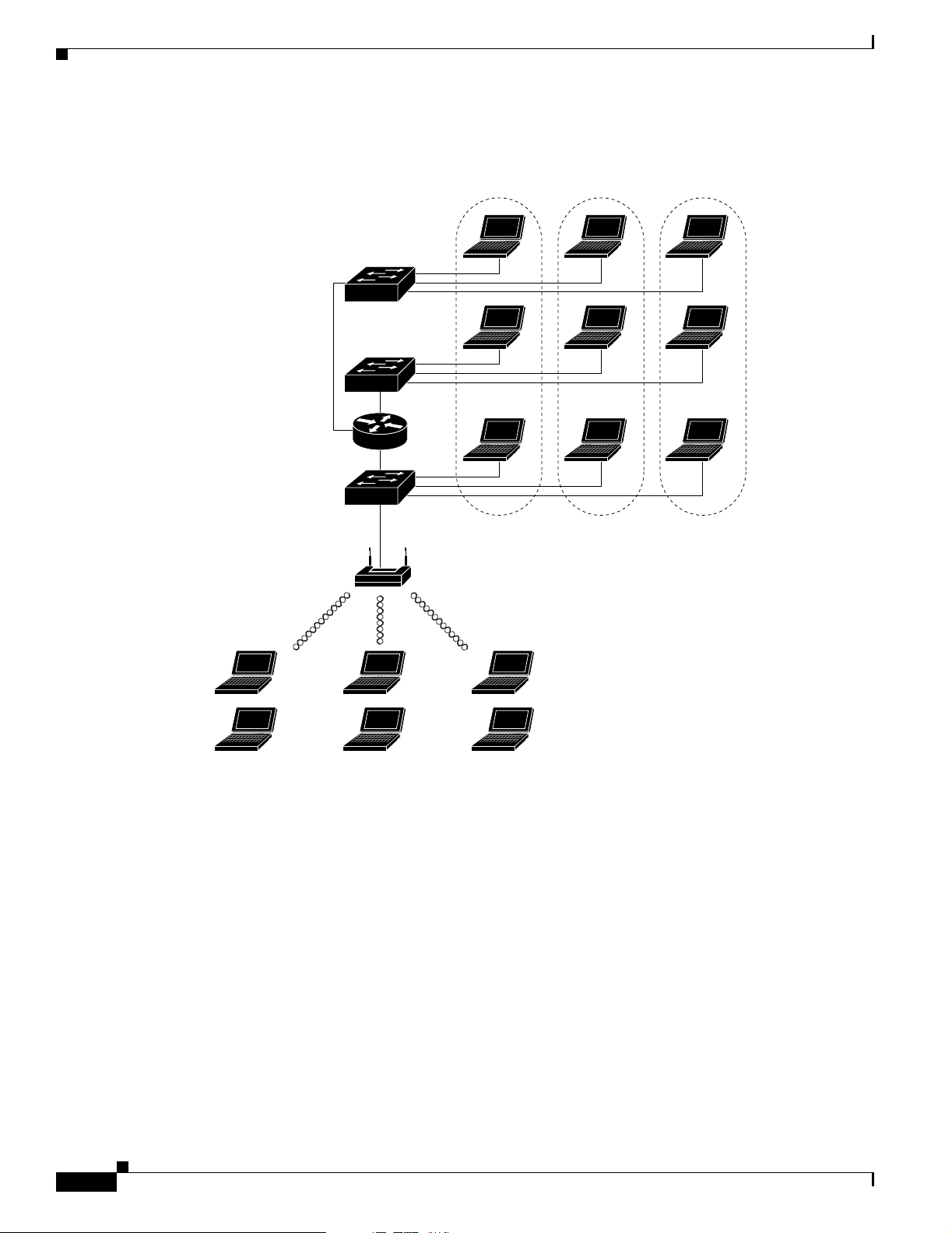
Figure 1-1 LAN Segmentation and VLAN Segmentation with Wireless Components
LAN 1
Catalyst
VLAN switch
VLAN segmentationTraditional LAN segmentation
VLAN 1
Chapter 1 Overview
VLAN 2 VLAN 3
SSID 0
Related Documents
Shared hub
LAN 2
Shared hub
LAN 3
Shared
hub
SSID 0 SSID 0 SSID 1 SSID 2 SSID 3
Floor 3
Floor 2
Floor 1
Catalyst
VLAN switch
Catalyst
VLAN switch
Trunk
port
SSID 1 = VLAN1
SSID 2 = VLAN2
SSID 3 = VLAN3
81652
The following documents provide more detailed information pertaining to VLAN design and
configuration:
• Cisco IOS Switching Services Configuration Guide
• Cisco Internetworking Design Guide
• Cisco Internetworking Technology Handbook
• Cisco Internetworking Troubleshooting Guide
Incorporating Wireless Devices into VLANs
A WLAN is generally deployed in an enterprise campus or branch office for increased efficiency and
flexibility. WLANs are one of the most effective methods for connecting to an enterprise network. With
version 12.01T1, you can configure your wireless devices to operate in a VLAN.
The basic wireless components of a VLAN consist of an access point and a set of clients associated to it
using wireless technology. The access point is physically connected through a trunk port to the network
switch on which the VLAN is configured. The physical connection to the VLAN switch is through the
access point’s Ethernet port.
Cisco Aironet 1200 Series Access Point Software Configuration Guide
1-6
OL-2159-05
Page 25

Chapter 1 Overview
A VLAN Example
VLAN Support
In fundamental terms, the key to configuring an access point to connect to a specific VLAN is by
configuring an SSID to map to that VLAN. Because VLANs are identified by a VLAN ID, it follows that
if an SSID on an access point is configured to map to a specific VLAN ID, a connection to the VLAN is
established. When this connection is made, associated wireless client devices having the same SSID are
able to access the VLAN through the access point. The VLAN processes data to and from the clients the
same way that it processes data to and from wired connections. The fact that the client is wireless has no
impact on the VLAN.
The VLAN feature now enables users to deploy wireless devices with greater efficiency and flexibility.
For example, one access point can now handle the specific requirements of multiple users having widely
varied network access and permissions. Without VLAN capability, multiple access points, one for each
VLAN, would have to be employed to serve classes of users based on the access and permissions they
were assigned.
The following simplified example shows how wireless devices can be used effectively in a VLAN
environment on a college campus. In this example, three levels of access are available through VLANs
configured on the physical network:
• Student access—lowest level of access; ability to access school’s intranet, obtain class schedules
and grades, make appointments, and perform other student-related activities
• Faculty access—medium level of access; ability to access internal files, read to and write from
student databases, access the intranet and Internet, and access internal information such as human
resources and payroll information
• Management access—highest level of access; ability to access all internal drives and files, and
perform management activities
In this scenario, a minimum of three VLAN connections would be required: one for each level of access
discussed above. The access point can handle up to 16 SSIDs; therefore, the following basic design could
be employed as shown in Table 1-1
.
Table 1-1 Access Level SSID and VLAN Assignment
Level of Access SSID VLAN ID
Student Student 01
Faculty Faculty 02
Management Management 03
Using this design, setting up the clients is based on the level of access each user requires. A typical
network diagram using this design would look like the one shown in Figure 1-2.
OL-2159-05
Cisco Aironet 1200 Series Access Point Software Configuration Guide
1-7
Page 26
Network Configuration Examples
Figure 1-2 VLAN Example
Catalyst
VLAN switch
Catalyst
VLAN switch
Catalyst
VLAN switch
Router
VLAN segmentation
VLAN 01 VLAN 02
Chapter 1 Overview
VLAN 03
Trunk port
Access point SSID Student=VLAN 01,
Students
SSID: Student
Faculty
SSID: Faculty
Management
SSID: Management
Network Configuration Examples
This section describes the access point’s role in three common wireless network configurations. The
access point’s default configuration is as a root unit connected to a wired LAN or as the central unit in
an all-wireless network. The repeater role requires a specific configuration.
SSID Faculty=VLAN 02, and
SSID Management=VLAN 03.
81661
Root Unit on a Wired LAN
An access point connected directly to a wired LAN provides a connection point for wireless users. If
more than one access point is connected to the LAN, users can roam from one area of a facility to another
without losing their connection to the network. As users move out of range of one access point, they
automatically connect to the network (associate) through another access point. The roaming process is
seamless and transparent to the user. Figure 1-3 shows access points acting as root units on a wired LAN.
Cisco Aironet 1200 Series Access Point Software Configuration Guide
1-8
OL-2159-05
Page 27
Chapter 1 Overview
Network Configuration Examples
Figure 1-3 Access Points as Root Units on a Wired LAN
Access Point
(Root Unit)
Repeater Unit that Extends Wireless Range
Wired LAN
Access Point
(Root Unit)
65999
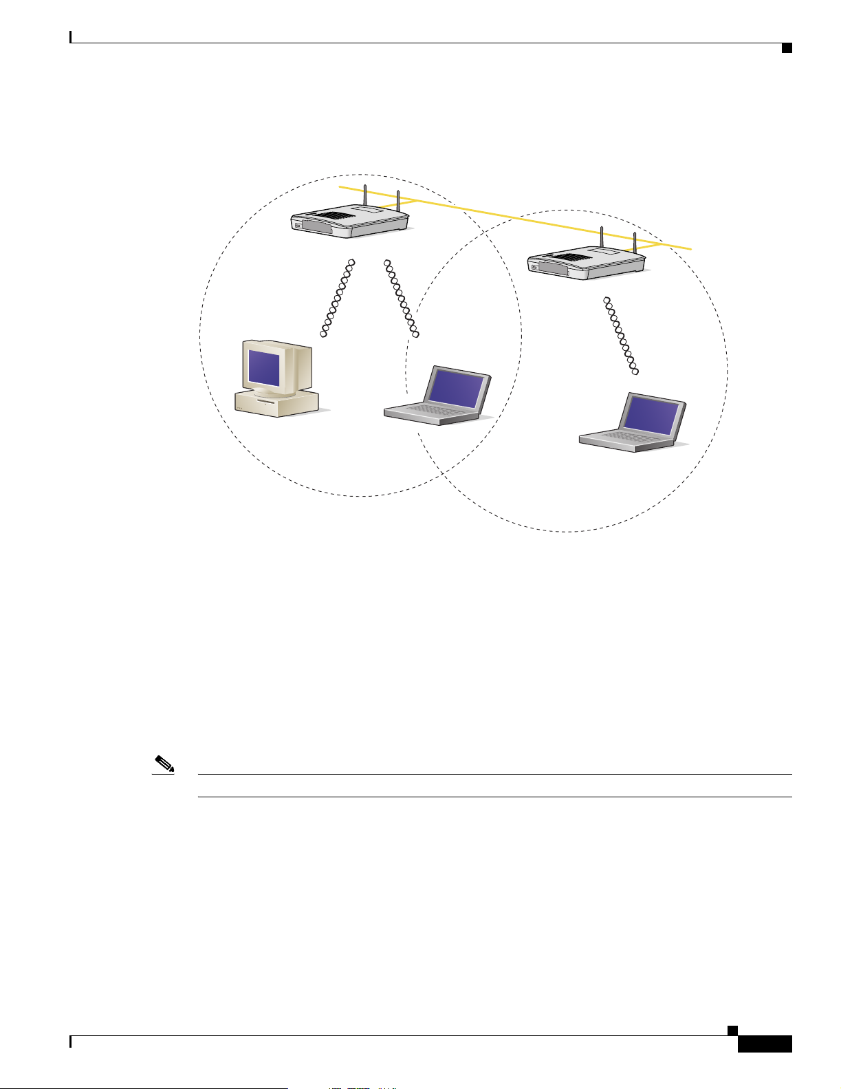
An access point can be configured as a stand-alone repeater to extend the range of your infrastructure or
to overcome an obstacle that blocks radio communication. The repeater forwards traffic between
wireless users and the wired LAN by sending packets to either another repeater or to an access point
connected to the wired LAN. The data is sent through the route that provides the best performance for
the client. You can set up either of the radios in your access point as a repeater, but one radio must be
set up as a root unit.
Figure 1-4 shows an access point acting as a repeater. Consult the Setting Up a Repeater Access Point,
chp 11 for instructions on setting up the access point as a repeater.
Note Non-Cisco client devices might have difficulty communicating with repeater access points.
OL-2159-05
Cisco Aironet 1200 Series Access Point Software Configuration Guide
1-9
Page 28
Network Configuration Examples
Figure 1-4 Access Point as Repeater
Chapter 1 Overview
Access Point
(Root Unit)
Wired LAN
Access Point
(Repeater)
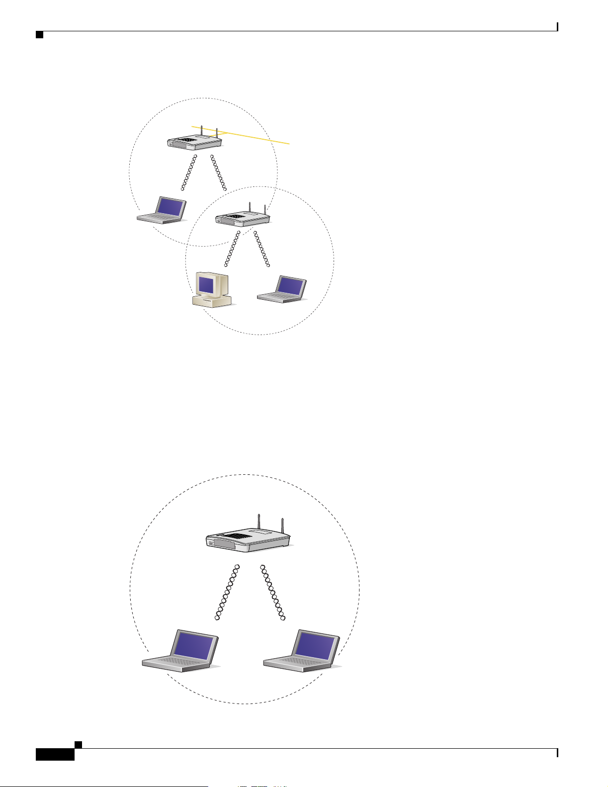
Central Unit in an All-Wireless Network
In an all-wireless network, an access point acts as a stand-alone root unit. The access point is not
attached to a wired LAN; it functions as a hub linking all stations together. The access point serves as
the focal point for communications, increasing the communication range of wireless users. Figure 1-5
shows an access point in an all-wireless network.
Figure 1-5 Access Point as Central Unit in All-Wireless Network
Access Point
(Root Unit)
66000
1-10
65998
Cisco Aironet 1200 Series Access Point Software Configuration Guide
OL-2159-05
Page 29

CHAPTER
2
Using the Management Interfaces
This chapter describes the interfaces you can use to configure the access point. You can use a
web-browser interface, a command-line interface through a terminal emulator or a Telnet session, or a
Simple Network Management Protocol (SNMP) application. The access point’s management system
web pages are organized the same way for the web browser and command-line interfaces. The examples
in this manual show the web-browser interface.
This chapter contains the following sections:
• Using the Web-Browser Interface, page 2-2
• Using the Command-Line Interface, page 2-4
• Using SNMP, page 2-7
OL-2159-05
Cisco Aironet 1200 Series Access Point Software Configuration Guide
2-1
Page 30

Using the Web-Browser Interface
Using the Web-Browser Interface
The web-browser interface contains management pages that you use to change access point settings,
upgrade and distribute firmware, and monitor and configure other wireless devices on the network.
Note The access point management system is fully compatible with Microsoft Internet Explorer versions 4.0
or later and Netscape Communicator versions 4.0 or later. Earlier versions of these browsers cannot use
all features of the management system.
Using the Web-Browser Interface for the First Time
Use the access point’s IP address to browse to the management system. See the Quick Start Guide: Cisco
Aironet 1200 Series Access Points for instructions on assigning an IP address to the access point.
Follow these steps to begin using the web-browser interface:
Step 1 Start the browser.
Chapter 2 Using the Management Interfaces
Step 2 Enter the access point’s IP address in the browser Location field (Netscape Communicator) or Address
field (Internet Explorer) and press Enter.
If the access point has not been configured, the Express Setup page appears. If the access point has been
configured, the Summary Status page appears.
Using the Management Pages in the Web-Browser Interface
The system management pages use consistent techniques to present and save configuration information.
Navigation buttons appear at the top of the page, and configuration action buttons appear at the bottom.
You use the navigation buttons to display other management pages, and you use the configuration action
buttons to save or cancel changes to the configuration.
Note It’s important to remember that clicking your browser’s Back button is the same as clicking Cancel: if
you make changes on a management page, your changes are not applied when you click Back. Changes
are only applied when you click Apply or OK.
Table 2-1 lists the page links and buttons that appear on most management pages.
Table 2-1 Common Buttons on Management Pages
2-2
Button/Link Description
Navigation Links
Home Displays the Summary Status page.
Map Opens the Map window, which contains links to every
management page.
Network Displays the Network Ports page.
Cisco Aironet 1200 Series Access Point Software Configuration Guide
OL-2159-05
Page 31

Chapter 2 Using the Management Interfaces
Table 2-1 Common Buttons on Management Pages (continued)
Button/Link Description
Associations Displays the Association Table page, which provides a list of
Setup Displays the Setup page, which contains links to the
Logs Displays the Event Log page, which lists system events and
Help Displays the online help for the current window and the
Login Logs you into the access point’s management system for
Configuration Action Buttons
Apply Saves changes made on the page and remain on the page.
OK Saves changes made on the page and return to the previous
Cancel Discards changes to the page and return to the previous page.
Restore Defaults Returns all settings on the page to their default values.
Using the Web-Browser Interface
all devices on the wireless network and links to the devices.
management pages with configuration settings.
their severity levels.
online help table of contents.
access to all pages and features appropriate for your user
level.
page.
Navigating Using the Map Windows
The Map window appears when you click Map at the top of any management page. You can use the Map
window to jump quickly to any system management page, or to a map of your entire wireless network.
Note Your Internet browser must have Java enabled to use the map windows.
To display the sub-pages for each main page, click the bullet next to a main page link (Microsoft Internet
Explorer), or click expand next to a main page link (Netscape Communicator). In Figure 2-1, the
sub-pages for the Network Ports page are expanded.
Figure 2-1 Map Window with Network Ports Pages Expanded
OL-2159-05
Cisco Aironet 1200 Series Access Point Software Configuration Guide
2-3
Page 32

Using the Command-Line Interface
The Network Map window appears when you click Network Map in the Map window. You use the
Network Map window to open a new browser window displaying information for any device on your
wireless network. Figure 2-2 shows the Network Map window.
Figure 2-2 The Network Map Window
Chapter 2 Using the Management Interfaces
Click the name of a wireless device to open a new browser window displaying a Station page listing the
access point’s local information for that device. Click Go beside the device name to open a new browser
window displaying that device’s home page, if available. Some devices, such as PC Card clients, might
not have home pages.
Click show clients to display all the wireless client devices on your network. The client names appear
under the access point or bridge with which they are associated. If clients are displayed, click hide
clients to display only non-client devices.
Using the Command-Line Interface
You can use a command-line interface (CLI) to configure your access point through a terminal emulation
program or a Telnet session instead of through your browser. This section provides instructions for
Microsoft’s HyperTerminal and for Telnet; other programs are similar.
Preparing to Use a Terminal Emulator
To use a terminal emulator to open the CLI, you need to:
1. Connect a nine-pin, female DB-9 to RJ-45 serial cable to the RJ-45 serial port on the access point
and to the COM port on a computer.
2-4
Note Make sure you use the standard Cisco rollover cable, part number AIR-CONBAB1200, to
make the connection.
2. Set up a terminal emulator to communicate with the access point. Use the following settings for the
terminal emulator connection: 9600 baud, 8 data bits, no parity, 1 stop bit, and no flow control.
Use the Console/Telnet Setup page to adjust the console and Telnet connection settings. See the
“Console and Telnet Setup” section on page 11-4 for details on the Console/Telnet Setup page.
Cisco Aironet 1200 Series Access Point Software Configuration Guide
OL-2159-05
Page 33

Chapter 2 Using the Management Interfaces
Connecting the Serial Cable
Connect a DB-9 to RJ-45 serial cable to the COM port on a computer and to the RJ-45 serial port on the
access point. Figure 2-3 shows the serial port connection.
Figure 2-3 Connecting the Serial Cable
Using the Command-Line Interface
DB-9 to RJ-45
serial cable
Note The Cisco part number for the DB-9 to RJ-45 serial cable is AIR-CONCAB1200. Browse to
http://www.cisco.com/go/marketplace to order a serial cable.
Setting Up the Terminal Emulator
Follow these steps to set up the terminal emulator:
Step 1 Open a terminal emulator.
Step 2 Enter these settings for the connection:
• Bits per second (baud rate): 9600
• Data bits: 8
• Parity: none
• Stop bits: 1
• Flow control: none
Step 3 Press = to display the home page of the access point. If the access point has not been configured before,
the Express Setup page appears as the home page. If the access point is already configured, the Summary
Status page appears as the home page.
RJ-45 serial
connector
74005
Changing Settings with the CLI
The CLI pages use consistent techniques to present and save configuration information. Table 2- 2 lists
the functions that appear on most CLI pages.
OL-2159-05
Cisco Aironet 1200 Series Access Point Software Configuration Guide
2-5
Page 34

Using the Command-Line Interface
Table 2-2 Common Functions on CLI Pages
Function Description
Press Enter
three times
Ctrl-R Refreshes the page and cancel changes to settings.
= Returns to the home page without applying changes.
:back Moves back one page without applying changes.
:bottom Jumps to the bottom of a long page, such as Event Log. When
:down Moves down one page length (24 lines) on a long page, such
You can also enter diagnostic commands in the CLI. See the “Using Command-Line Diagnostics”
section on page 13-15 for information on the CLI diagnostic commands.
Chapter 2 Using the Management Interfaces
Refreshes the page and cancel changes to settings.
you are at the bottom of a page, this function becomes :top.
as Event Log. When you are at the bottom of a long page, this
function becomes :up.
Figure 2-4 shows a CLI page example.
Figure 2-4 CLI Page Example
Selecting Pages and Settings
When you type names and settings that appear in brackets you jump to that page or setting.
HyperTerminal jumps to the page or setting as soon as it recognizes a unique name, so you only need to
type the first few characters in the page or setting name. To jump from the home page to the Setup page,
for example, you only need to type se.
Cisco Aironet 1200 Series Access Point Software Configuration Guide
2-6
OL-2159-05
Page 35

Chapter 2 Using the Management Interfaces
Applying Changes to the Configuration
The CLI’s auto-apply feature is on by default, so changes you make to any page are applied automatically
when you move to another management page. To apply changes and stay on the current page, type apply
and press Enter.
Using a Telnet Session
Follow these steps to browse to the CLI pages with Telnet:
Step 1 On your computer’s Start menu, select Programs > Accessories > Telnet.
If Telnet is not listed in your Accessories menu, select Start > Run, type Tel ne t in the entry field, and
press Enter.
Step 2 When the Telnet window appears, click Connect and select Remote System.
Note In Windows 2000, the Telnet window does not contain pull-down menus. To start the Telnet
session in Windows 2000, type open followed by the access point’s IP address.
Using SNMP
Step 3 In the Host Name field, type the access point’s IP address and click Connect.
Note Access point firmware 12.00T and above supports Secure Shell (SSH) sessions. See the “Using Secure
Shell” section on page 11-5 for more information.
Using SNMP
You use an SNMP management application to configure the access point with SNMP. Follow these steps
to configure the access point with SNMP:
Step 1 Compile the MIB you need to use in your SNMP management application. MIBs supported by the access
point are listed in Supported MIBs.
Step 2 Use a web browser, a Telnet session, or the console interface to open the Express Setup page in the access
point management system.
Step 3 Enter an SNMP community name in the SNMP Admin. Community field and click OK or Apply.
Step 4 Follow this link path to reach the SNMP Setup page:
a. On the Summary Status page, click Setup.
OL-2159-05
b. On the Setup page, click SNMP in the Services section of the page.
Use the SNMP Setup page to enter detailed SNMP settings, such as the SNMP trap destination. See the
“SNMP Setup” section on page 11-2 for details on the SNMP Setup page.
Cisco Aironet 1200 Series Access Point Software Configuration Guide
2-7
Page 36

Using SNMP
Supported MIBs
The access point supports the following MIBs:
• Standard MIB-II (RFC1213-MIB.my)
• Cisco Discovery Protocol MIB (CISCO-CDP-MIB-V1SMI.my)
Chapter 2 Using the Management Interfaces
Supported branches:
–
system (1.3.6.1.2.1.1)
–
interfaces (1.3.6.1.2.1.2)
–
ip (1.3.6.1.2.1.4)
–
tcp (1.3.6.1.2.1.6)
–
udp (1.3.6.1.2.1.7)
–
snmp (1.3.6.1.2.1.11)
To download this MIB, browse to
http://www.cisco.com/public/sw-center/netmgmt/cmtk/mibs.shtml and click SNMP v1 MIBs.
Scroll down the list of files and select RFC1213-MIB.my.
–
Supported branch: ciscoCdpMIB (1.3.6.1.4.1.9.23)
To download this MIB, browse to
http://www.cisco.com/public/sw-center/netmgmt/cmtk/mibs.shtml and click SNMP v1 MIBs.
Scroll down the list of files and select CISCO-CDP-MIB-V1SMI.my.
• Cisco Aironet Access Point MIB (AWC-VLAN-MIB.mib)
–
Supported branch: awcVx (1.3.6.1.4.1.522.3)
You can download the latest release of the access point MIB at the following URL:
http://www.cisco.com/public/sw-center/sw-wireless.shtml
• IEEE802dot11-MIB.my:
–
Supported branch: ieee802dot11 (1.2.840.10036)
To download this MIB, browse to
ftp://ftp.cisco.com/pub/mibs/v1/IEEE802dot11-MIB-V1SMI.my.
2-8
Cisco Aironet 1200 Series Access Point Software Configuration Guide
OL-2159-05
Page 37

CHAPTER
3
Radio Configuration and Basic Settings
This chapter describes how to use the pages in the access point management system to configure the
access point. The main Setup page provides links to all the pages containing access point settings.
This chapter contains the following sections:
• Basic Settings, page 3-2
• Radio Configuration, page 3-7
• Ethernet Configuration, page 3-23
Note See Chapter 8, “Security Setup” for information on setting up the access point’s security features.
OL-2159-05
Cisco Aironet 1200 Seres Access Point Software Configuration Guide
3-1
Page 38

Basic Settings
Basic Settings
This section describes the basic settings on the Express Setup page. If you need to set up an access point
quickly with a simple configuration, or change or update a basic setting, you can enter all the access
point’s essential settings for basic operation on the Express Setup page.
The page contains radio settings for both the 2.4-GHz internal radio and the 5-GHz external radio
module. You can configure the radios separately, using different settings on each radio. Figure 3-1 shows
the Express Setup page.
Figure 3-1 Express Setup Page
Chapter 3 Radio Configuration and Basic Settings
3-2
Follow this link path to reach the Express Setup page:
1. On the Summary Status page, click Setup.
2. On the Setup page, click Express Setup.
Cisco Aironet 1200 Seres Access Point Software Configuration Guide
OL-2159-05
Page 39

Chapter 3 Radio Configuration and Basic Settings
Entering Basic Settings
The Express Setup page contains the following settings:
• System Name
• MAC Address
• System Serial Number
• Configuration Server Protocol
• Default IP Address
• Default IP Subnet Mask
• Default Gateway
• Radio Service Set ID (SSID)
• Role in Radio Network
• Radio Network Optimization (Optimize Radio Network For)
• Radio Network Compatibility (Ensure Compatibility With)
• Security Setup Link
Basic Settings
• SNMP Admin. Community
System Name
The system name appears in the titles of the management system pages and in the access point’s
Association Table page. The system name is not an essential setting, but it helps identify the access point
on your network.
MAC Address
The access point’s Media Access Control (MAC) address appears under the system name. The MAC
address is a unique serial number permanently assigned to the access point’s Ethernet controller. You
cannot change the access point’s MAC address.
System Serial Number
The access point’s serial number appears under the MAC address. The serial number is a unique
identifying number assigned to the access point. You cannot change the access point’s serial number.
OL-2159-05
Cisco Aironet 1200 Seres Access Point Software Configuration Guide
3-3
Page 40

Basic Settings
Configuration Server Protocol
Set the Configuration Server Protocol to match the network's method of IP address assignment. Click
the Configuration Server link to jump to the Boot Server Setup page, which contains detailed settings
for configuring the access point to work with your network’s BOOTP or DHCP servers for automatic
assignment of IP addresses.
The Configuration Server Protocol pull-down menu contains the following options:
• None—Your network does not have an automatic system for IP address assignment.
• BOOTP—With Bootstrap Protocol, IP addresses are hard-coded based on MAC addresses.
• DHCP—With Dynamic Host Configuration Protocol, IP addresses are “leased” for predetermined
periods of time.
Default IP Address
Use this setting to assign or change the access point’s IP address. If DHCP or BOOTP is not enabled for
your network, the IP address you enter in this field is the access point’s IP address. If DHCP or BOOTP
is enabled, this field provides the IP address only if no server responds with an IP address for the access
point.
Chapter 3 Radio Configuration and Basic Settings
Default IP Subnet Mask
Enter an IP subnet mask to identify the subnetwork so the IP address can be recognized on the LAN. If
DHCP or BOOTP is not enabled, this field is the subnet mask. If DHCP or BOOTP is enabled, this field
provides the subnet mask only if no server responds to the access point’s DHCP or BOOTP request.
Default Gateway
Enter the IP address of your default internet gateway here. The entry 255.255.255.255 indicates no
gateway. Clicking the Gateway link takes you to the Routing Setup page, which contains detailed settings
for configuring the access point to communicate with the IP network routing system.
Radio Service Set ID (SSID)
An SSID is a unique identifier that client devices use to associate with the access point or a VLAN
supported by the access point. The SSID helps client devices distinguish between multiple wireless
networks and VLANs in the same vicinity and provides access to VLANs by wireless client devices.
Several access points on a network or subnetwork can share an SSID. You can configure up to 16 SSIDs
on each radio in the access point. An SSID can be any alphanumeric, case-sensitive entry from 2 to 32
characters long.
Click more to go to the AP Radio Service Sets page where you can create additional SSIDs. From this
page you can also edit an existing SSID or remove one from the system.
Role in Radio Network
Use this pull-down menu to select the role of the access point on your network. This setting appears
twice on the page, once for the internal radio and once for the external radio module. You can use the
same setting or different settings for each radio.
Cisco Aironet 1200 Seres Access Point Software Configuration Guide
3-4
OL-2159-05
Page 41

Chapter 3 Radio Configuration and Basic Settings
The menu contains the following options:
• Root Access Point—A wireless LAN transceiver that connects an Ethernet network with wireless
client stations. Use this setting if the access point is connected to the wired LAN. Figure 3-2 shows
an access point operating as a root unit in a network.
Figure 3-2 Root-Unit Access Points
Basic Settings
Access Point
(Root Unit)
Wired LAN
Access Point
(Root Unit)
•
Repeater Access Point—An access point that transfers data between a client and another access
point or repeater. One or both access point radios can be set up as repeaters. Figure 3-3 shows an
access point operating as a repeater in a network.
65999
OL-2159-05
Note Non-Cisco client devices might have difficulty communicating with repeater access points.
Cisco Aironet 1200 Seres Access Point Software Configuration Guide
3-5
Page 42

Basic Settings
Chapter 3 Radio Configuration and Basic Settings
Figure 3-3 Repeater Access Point
Access Point
(Root Unit)
Wired LAN
Access Point
(Repeater)
• Site Survey Client—A wireless device that depends on an access point for its connection to the
network. Use this setting when performing a site survey for a repeater access point. When you select
this setting, clients are not allowed to associate.
Radio Network Optimization (Optimize Radio Network For)
You use this setting to select either preconfigured settings for the access point radio or customized
settings for the access point radio. This setting appears twice on the page, once for the internal radio and
once for the external radio module. You can use the same setting or different settings for each radio.
• Default—Strikes a compromise between range and throughput, providing good range and good
throughput.
• Throughput—Maximizes the data volume handled by the access point but might reduce the access
point’s range.
• Range—Maximizes the access point’s range but might reduce throughput.
• Custom—The access point uses the settings you enter on the AP Radio Hardware page. Click
Custom to go to the AP Radio Hardware page.
Security Setup Link
66000
3-6
When VLANs are enabled, clicking on this link takes you to the Security Setup page, where you can
configure security-related parameters. See the SETTING UP ADMINISTRATOR AUTH CHP8.
Cisco Aironet 1200 Seres Access Point Software Configuration Guide
OL-2159-05
Page 43

Chapter 3 Radio Configuration and Basic Settings
Radio Network Compatibility (Ensure Compatibility With)
You use this setting to automatically configure the access point to be compatible with other devices on
your wireless LAN. This setting appears twice on the page, once for the internal radio and once for the
external radio module. You can use the same setting or different settings for each radio.
• 2Mb/sec clients—Select this setting if your network contains Cisco Aironet devices that operate at
a maximum speed of 2 Mbps.
• non-Aironet 802.11—Select this setting if there are non-Cisco Aironet devices on your wireless
LAN.
Security Setup Link
Clicking on this link takes you to the Security Setup page from which you can manage security issues
on the access point. Settings on this page are covered in the “Setting Up Administrator Authorization”
section on page 8-32.
SNMP Admin. Community
Radio Configuration
To use Simplified Network Management Protocol (SNMP), enter a community name here. This name
automatically appears in the list of users authorized to view and make changes to the access point’s
management system, and SNMP is enabled.
Click the SNMP link to go to the SNMP Setup page, where you can edit other SNMP settings.
You can define other SNMP communities on the Administrator Authorization pages. See the “Setting Up
Administrator Authorization” section on page 8-32 for instructions on using the Administrator
Authorization pages.
Radio Configuration
This section describes how to configure the access point radios. You use the AP Radio pages in the
management system to set the configuration for each radio. The radio pages include:
• AP Radio Identification pages—Contain the basic locating and identity information for the access
point internal and module radio ports. See the “Entering Identity Information” section on page 3-8
for instructions on using the AP Radio Identification pages.
• AP Radio Hardware pages—Contain settings for the access point’s SSID, data rates, transmit power,
antennas, radio channel, and operating thresholds for the access point internal and module radio
ports. See the “Entering Radio Hardware Information” section on page 3-10 for instructions on
using the AP Radio Hardware pages.
• AP Radio Advanced pages—Contain settings for the operational status of the access point’s internal
and module radio ports. You can also use these pages to make temporary changes in port status to
help with troubleshooting network problems. See the “Entering Advanced Configuration
Information” section on page 3-15 for instructions on using the AP Radio Advanced pages.
OL-2159-05
• AP Radio Ports pages—List key information on the access point’s radio ports.
Cisco Aironet 1200 Seres Access Point Software Configuration Guide
3-7
Page 44

Radio Configuration
Entering Identity Information
Use the AP Radio Identification pages to enter basic locating and identity information for the access
point radios. The internal radio and the radio module both have an AP Radio Identity page. Both pages
contain the same settings. Figure 3-4 shows the AP Radio Identification page for the internal radio.
Figure 3-4 The AP Radio Identification Page for the Internal Radio
Chapter 3 Radio Configuration and Basic Settings
Follow this link path to reach the AP Radio Identification page:
1. On the Summary Status page, click Setup.
2. On the Setup page, click Identification in on eof the AP Radio rows under Network Ports.
Settings on the AP Radio Identification Page
The AP Radio Identification pages contain the following settings:
• Primary Port Settings
• Default IP Address
• Default IP Subnet Mask
• Service Set ID (SSID)
• LEAP User Name
• LEAP Password
The page also displays the access point’s MAC address, the radio serial number, the radio’s current IP
address, the radio’s current IP subnet mask, the maximum packet length that the radio can send and
receive, the radio firmware version, and the radio boot block version.
3-8
Cisco Aironet 1200 Seres Access Point Software Configuration Guide
OL-2159-05
Page 45

Chapter 3 Radio Configuration and Basic Settings
Primary Port Settings
Two options allow you to designate the radio port as the Primary Port and select whether the radio port
adopts or assumes the identity of the primary port.
• Primary Port?—The primary port determines the access point’s MAC and IP addresses. Ordinarily,
the access point’s primary port is the Ethernet port, which is connected to the wired LAN, so this
setting is usually set to no. Select no to set the Ethernet port as the primary port. Select yes to set
the radio port as the primary port.
• Adopt Primary Port Identity?—Select yes to adopt the primary port settings (MAC and IP addresses)
for the radio port. Select no to use different MAC and IP addresses for the radio port.
Access points acting as root units adopt the primary port settings for the radio port. When you put
an access point in standby mode, however, you select no for this setting. Some advanced wireless
bridge configurations also require different identity settings for the radio port.
Default IP Address
Use this setting to assign an IP address for the radio port that is different from the access point’s Ethernet
IP address. During normal operation the radio port adopts the identity of the Ethernet port. When you
put an access point in standby mode, however, you assign a different IP address to the radio port. Some
advanced wireless bridge configurations also require a different IP address for the radio port.
Radio Configuration
Default IP Subnet Mask
Service Set ID (SSID)
LEAP User Name
Enter an IP subnet mask to identify the subnetwork so that the IP address can be recognized on the LAN.
If DHCP or BOOTP is not enabled, this field is the subnet mask. If DHCP or BOOTP is enabled, this
field provides the subnet mask only if no server responds to the access point’s request.
The current IP subnet mask displayed under the setting shows the IP subnet mask currently assigned to
the access point. This is the same subnet mask as the default subnet mask unless DHCP or BOOTP is
enabled. If DHCP or BOOTP is enabled, this is the subnet mask used by the DHCP or BOOTP server.
You can also enter this setting on the Express Setup page.
An SSID is a unique identifier that client devices use to associate with the access point or a VLAN
supported by the access point. The SSID helps client devices distinguish between multiple wireless
networks and VLANs in the same vicinity and provides access to VLANs by wireless client devices.
Several access points on a network or subnetwork can share an SSID. You can configure up to 16 SSIDs
per radio on an access point. An SSID can be any alphanumeric, case-sensitive entry from 2 to 32
characters long.
Click more to go to the AP Radio Service Sets page where you can create additional SSIDs. From this
page you can also edit an existing SSID or remove one from the system.
You can also enter this setting on the Express Setup page.
OL-2159-05
Use this field if the radio is set up as a repeater and authenticates to the network using LEAP. When the
radio authenticates using LEAP, the access point sends this user name to the authentication server.
Follow the steps in the “Setting Up a Repeater Access Point” section on page 12-2 to set up the radio as
a LEAP client.
Cisco Aironet 1200 Seres Access Point Software Configuration Guide
3-9
Page 46

Radio Configuration
LEAP Password
Use this field if the radio is set up as a repeater and authenticates to the network using LEAP. When the
radio authenticates using LEAP, the access point uses this password for authentication.
Follow the steps in the “Setting Up a Repeater Access Point” section on page 12-2 set up the radio as a
LEAP client.
Entering Radio Hardware Information
You use the AP Radio Hardware pages to assign settings related to the access point’s radio hardware.
The internal radio and the radio module both have an AP Radio Hardware page. Both pages contain
similar settings. Figure 3-5 shows the AP Radio Hardware page for the radio module.
Figure 3-5 The AP Radio Hardware Page for the Radio Module
Chapter 3 Radio Configuration and Basic Settings
3-10
Follow this link path to reach the AP Radio Hardware pages:
1. On the Summary Status page, click Setup.
2. On the Setup page, click Hardware in one of the AP Radio rows under Network Ports.
Cisco Aironet 1200 Seres Access Point Software Configuration Guide
OL-2159-05
Page 47

Chapter 3 Radio Configuration and Basic Settings
Settings on the AP Radio Hardware Page
The AP Radio Hardware page contains the following settings:
• Service Set ID (SSID)
• Allow Broadcast SSID to Associate?
• Enable World Mode
• Data Rates
• Transmit Power
• Frag. Threshold
• RTS T h reshold
• Max. RTS Retries
• Max. Data Retries
• Beacon Period
• Data Beacon Rate (DTIM)
• Default Radio Channel
• Search for Less-Congested Radio Channel
Radio Configuration
• Restrict Searched Channels
• Receive Antenna and Transmit Antenna
The AP Radio Hardware page also contains a link to the AP Radio Data Encryption Setup and VLAN
Setup pages, which you can use to configure the radio’s data encryption. Which link you choose depends
on whether you are using VLANs. If VLANs are not enabled, use the Radio Data Encryption (WEP) link
to configure the radio’s data encryption settings. If VLANs are enabled, use the VLAN Setup link to
configure the radio data encryption.
Service Set ID (SSID)
An SSID is a unique identifier that client devices use to associate with the access point or a VLAN
supported by the access point. The SSID helps client devices distinguish between multiple wireless
networks and VLANs in the same vicinity and provides access to VLANs by wireless client devices.
Several access points on a network or subnetwork can share an SSID. You can configure up to 16 SSIDs
per radio on an access point. An SSID can be any alphanumeric, case-sensitive entry from 2 to 32
characters long.
Click more to go to the AP Radio Service Sets page where you can create additional SSIDs. From this
page you can also edit an existing SSID or remove one from the system.
You can also enter this setting on the Express Setup and AP Radio Identification pages.
Allow Broadcast SSID to Associate?
You use this setting to choose whether devices that do not specify an SSID (devices that are
“broadcasting” in search of an access point to associate with) are allowed to associate to this radio.
OL-2159-05
• Ye s—This is the default setting; it allows devices using the primary SSID that do not specify an
SSID (devices that are “broadcasting” in search of an access point or bridge to associate with) to
associate with the radio using the primary SSID.
Cisco Aironet 1200 Seres Access Point Software Configuration Guide
3-11
Page 48

Radio Configuration
Enable World Mode
Data Rates
Chapter 3 Radio Configuration and Basic Settings
• No—Devices that do not specify an SSID (devices that are “broadcasting” in search of an access
point or bridge to associate with) are not allowed to associate with the access point or bridge. With
No selected, the SSID used by the client must exactly match one of the radio’s SSID.
When you select yes from the world-mode pull-down menu, the access point adds channel carrier set
information to its beacon. Client devices with world-mode enabled receive the carrier set information
and adjust their settings automatically.
You use the data rate settings to choose the data rates the radio uses for data transmission. The rates are
expressed in megabits per second.
The access point always attempts to transmit at the highest data rate set to Basic. If there are obstacles
or interference, the access point steps down to the highest rate that allows data transmission. For each
data rate, a drop-down menu lists three options:
• Basic—Allows transmission at this rate for all packets, both unicast and multicast. At least one of
the access point’s data rates must be set to Basic.
• Ye s—The access point transmits only unicast packets at this rate; multicast packets are sent at one
of the data rates set to Basic.
• No—The access point does not transmit data at this rate.
You can use the Data Rate settings to set up an access point to serve client devices operating at specific
data rates. For example, to set up the internal radio for 11 megabits per second (Mbps) service only,
select Basic for 11 and select Ye s for the other data rates. Figure 3-6 shows the Data Rates set up for
11-Mbps service only.
Figure 3-6 Data Rate Settings for 11 Mbps Service Only
To set up the access point to serve only client devices operating at 1 and 2 Mbps, for example, select
Basic for 1 and 2 and set the rest of the data rates to Yes . Figure 3-7 shows the Data Rates set up for 1-
and 2-Mbps service only.
Figure 3-7 Data Rate Settings for 1- and 2-Mbps Service Only
The Optimize Radio Network For setting on the Express Setup page selects the data rate settings
automatically. When you select Optimize Radio Network For Throughput on the Express Setup page,
all data rates are set to basic. When you select Optimize Radio Network For Range on the Express
Setup page, the lowest data rate (1.0 on the internal radio and 6.0 on the radio module) is set to basic,
and the other data rates are set to yes. If you leave the setting at Default for the internal radio, the 1.0
and 5.5 data rates are set to basic and the 2.0 and 11.0 data rates are set to yes (on the radio module, 6.0,
12.0, and 24.0 are set to basic and 9.0, 18.0, 36.0, 48.0, and 54.0 are set to yes).
3-12
Cisco Aironet 1200 Seres Access Point Software Configuration Guide
OL-2159-05
Page 49

Chapter 3 Radio Configuration and Basic Settings
Transmit Power
This setting determines the power level of radio transmission. The default power setting is the highest
transmit power allowed in your regulatory domain.
Note Government regulations define the highest allowable power level for radio devices. This setting must
conform to established standards for the country in which you use the access point.
To reduce interference or to conserve power, select a lower power setting. The settings in the drop-down
menu for the internal radio include 1, 5, 20, 50, and 100 milliwatts. The settings in the drop-down menu
for the radio module include 5, 8, 11, and 14 milliwatts.
Note The power settings available on your access point depend on the regulatory domain for which the access
point is configured. Your power settings might be different from the settings listed here.
Frag. Threshold
This setting determines the size at which packets are fragmented (sent as several pieces instead of as one
block). Enter a setting ranging from 256 to 2338 bytes. Use a low setting in areas where communication
is poor or where there is a great deal of radio interference.
Radio Configuration
RTS Threshold
This setting determines the packet size at which the access point issues a request to send (RTS) before
sending the packet. A low RTS Threshold setting can be useful in areas where many client devices are
associating with the access point, or in areas where the clients are far apart and can detect only the access
point and not each other. Enter a setting ranging from 0 to 2339 bytes.
Max. RTS Retries
The maximum number of times the access point issues an RTS before stopping the attempt to send the
packet through the radio. Enter a value from 1 to 128.
Max. Data Retries
The maximum number of attempts the access point makes to send a packet before giving up and dropping
the packet.
Beacon Period
The amount of time between beacons in Kilomicroseconds. One Kµsec equals 1,024 microseconds.
Data Beacon Rate (DTIM)
This setting, always a multiple of the beacon period, determines how often the beacon contains a delivery
traffic indication message (DTIM). The DTIM tells power-save client devices that a packet is waiting for
them.
OL-2159-05
If the beacon period is set at 100, its default setting, and the data beacon rate is set at 1, its default setting,
then the access point sends a beacon containing a DTIM every 100 Kµsecs. One Kµsec equals 1,024
microseconds.
Cisco Aironet 1200 Seres Access Point Software Configuration Guide
3-13
Page 50

Radio Configuration
Note If client devices using power-save mode wake up too often when associated to the access point, increase
Default Radio Channel
Chapter 3 Radio Configuration and Basic Settings
the data beacon rate setting.
The default channel settings on the radios are the lowest channel numbers for your regulatory domain.
In North America, the default setting for the internal radio is channel 1 transmitting at 2412 MHz, and
the default setting for the radio module is channel 36 transmitting at 5180 MHz. To overcome
interference problems, other channel settings are available from the radio channel pull-down menus.
The internal radio operates on 11 channels from 2412 to 2462 MHz. Each channel covers 22 MHz. The
bandwidth for channels 1, 6, and 11 does not overlap, so you can set up multiple access points in the
same vicinity without causing interference.
The radio module operates on eight channels from 5180 to 5320 MHz. Each channel on the radio module
covers 20 MHz, and the bandwidth for the channels overlaps slightly. For best performance, use channels
that are not adjacent (44 and 46, for example) for radios that are close to each other.
Note Too many access points in the same vicinity creates radio congestion that can reduce throughput. A
careful site survey can determine the best placement of access points for maximum radio coverage and
throughput.
Search for Less-Congested Radio Channel
When you select yes from the Search for less-congested radio channel pull-down menu, the access point
scans for the radio channel that is least busy and selects that channel for use. The access point scans at
power-up and when the radio settings are changed.
Note If you need to keep the access point assigned to a specific channel to keep from interfering with other
access points, you should leave this setting at no.
Restrict Searched Channels
Click Restrict Searched Channels to limit the channels that the access point scans when Search for
less-congested radio channel is enabled. The AP Radio Restrict Searched Channels page appears when
you click Restrict Searched Channels. Figure 3-8 shows the AP Radio Restrict Searched Channels page
for the internal radio.
3-14
Cisco Aironet 1200 Seres Access Point Software Configuration Guide
OL-2159-05
Page 51

Chapter 3 Radio Configuration and Basic Settings
Figure 3-8 AP Radio Restrict Searched Channels Page for the Internal Radio
The page lists all the channels in the access point’s regulatory domain. Click the Search check boxes
beside the channels to include channels in the scan for less-congested channels. All the channels are
included in the scan by default.
Radio Configuration
Receive Antenna and Transmit Antenna
Pull-down menus for the receive and transmit antennas offer three options:
• Diversity—This default setting tells the access point to use the antenna that receives the best signal.
If your access point has two fixed (non-removable) antennas, you should use this setting for both
receive and transmit.
• Right—If your access point has removable antennas and you install a high-gain antenna on the
access point’s right connector, you should use this setting for both receive and transmit. When you
look at the access point’s back panel, the right antenna is on the right.
• Left—If your access point has removable antennas and you install a high-gain antenna on the access
point’s left connector, you should use this setting for both receive and transmit. When you look at
the access point’s back panel, the left antenna is on the left.
Note The access point receives and transmits using one antenna at a time, so you cannot increase range by
installing high-gain antennas on both connectors and pointing one north and one south. When the access
point used the north-pointing antenna, it would ignore client devices to the south.
Entering Advanced Configuration Information
Use the AP Radio Advanced pages to assign special configuration settings for the access point radios.
The internal radio and the radio module both have an AP Radio Advanced page. Both pages contain the
same settings, but the Advanced page for the external radio module does not contain the Radio
Modulation and Radio Preamble settings. Figure 3-9 shows the AP Radio Advanced page for the internal
radio.
OL-2159-05
Cisco Aironet 1200 Seres Access Point Software Configuration Guide
3-15
Page 52

Radio Configuration
Chapter 3 Radio Configuration and Basic Settings
Figure 3-9 AP Radio Advanced Page for Internal Radio
3-16
Follow this link path to reach the AP Radio Advanced pages:
1. On the Summary Status page, click Setup.
2. On the Setup page, click Advanced in one of the AP Radio rows under Network Ports.
Cisco Aironet 1200 Seres Access Point Software Configuration Guide
OL-2159-05
Page 53

Chapter 3 Radio Configuration and Basic Settings
Settings on the AP Radio Advanced Page
The AP Radio Advanced pages contain the following settings:
• Requested Status
• Packet Forwarding
• Default Multicast Address Filters
• Maximum Multicast Packets/Second
• Radio Cell Role
• SSID For Use By Infrastructure Stations
• Disallow Infrastructure Stations on Any Other SSID
• Use Aironet Extensions
• Classify Workgroup Bridges as Network Infrastructure
• Require Use of Radio Firmware x.xx
• Ethernet Encapsulation Transform
• Quality of Service Setup Link
• Enhanced MIC verification for WEP
Radio Configuration
Requested Status
Packet Forwarding
• Temporal Key Integrity Protocol
• Broadcast WEP Key rotation interval (sec)
• Preferred Access Points
• Radio Modulation
• Radio Preamble
• Non-Root Mobility
The AP Radio Advanced page also contains links to the VLAN Setup page, Quality of Service Setup
page, and Advanced Primary SSID Setup page.
This setting is useful for troubleshooting problems on your network. Up, the default setting, turns the
radio on for normal operation. Down turns the radio off.
The Current Status line under the setting displays the current status of the radio port. This field can also
display Error, meaning the port is operating but is in an error condition.
This setting is always set to Enabled for normal operation. For troubleshooting, you might want to set
packet forwarding to Disabled, which prevents data from moving between the Ethernet and the radio.
The Forwarding State line under the setting displays the current forwarding state. For normal access
point operation, the forwarding state is Forwarding. Four other states are possible:
OL-2159-05
• Unknown—The state cannot be determined.
• Disabled—Forwarding capabilities are disabled.
• Blocking—The port is blocking transmission. This is the state when no stations are associated.
• Broken—This state reports radio failure.
Cisco Aironet 1200 Seres Access Point Software Configuration Guide
3-17
Page 54

Radio Configuration
Default Multicast Address Filters
MAC address filters allow or disallow the forwarding of multicast packets sent to specific MAC
addresses. You can create a filter that passes traffic to all MAC addresses except those you specify, or
you can create a filter that blocks traffic to all MAC addresses except those you specify. Read the
“Creating a MAC Address Filter” section on page 5-7 for complete instructions on setting up MAC
address filters.
The pull-down menus for multicast address filters contain two options:
• Allowed—The access point forwards all traffic except packets sent to the MAC addresses listed as
disallowed on the Address Filters page.
• Disallowed—The access point discards all traffic except packets sent to the MAC addresses listed
as allowed on the Address Filters page.
Note If you plan to discard traffic to all MAC addresses except those you specify (the Disallowed setting), be
sure to enter your own MAC address as allowed on the Address Filters page to prevent being locked out
of the access point.
Chapter 3 Radio Configuration and Basic Settings
Maximum Multicast Packets/Second
Use this setting to control the number of multicast packets that can pass through the radio port each
second. If you enter 0, the access point passes an unlimited number of multicast packets. If you enter a
number other than 0, the device passes only that number of multicast packets per second.
Radio Cell Role
Use this pull-down menu to select the function of the radio within its radio coverage area (cell). This
setting determines how the radio interacts with other wireless devices. The menu contains the following
options:
• Root—A wireless LAN transceiver that connects an Ethernet network with wireless client stations
or with another Ethernet network. Use this setting if the access point is connected to the wired LAN.
• Repeater/Non-Root—A wireless LAN transceiver that transfers data between a client and another
access point. Use this setting for access points not connected to the wired LAN.
• Client/Non-root—A station with a wireless connection to an access point. Use this setting for
diagnostics or site surveys, such as when you need to test the radio by having it communicate with
another access point or bridge without accepting associations from client devices.
SSID For Use By Infrastructure Stations
Use this entry field to identify the SSID to be used by repeaters and workgroup bridges to associate to
the access point. This SSID should be mapped to the native VLAN ID in order to facilitate
communications between infrastructure devices and a non-root access point or bridge.
Disallow Infrastructure Stations on Any Other SSID
Use this setting to prevent repeaters and workgroup bridges from associating to SSIDs other than the
infrastructure SSID. The default setting is No, so to invoke this condition, you must change the setting
to Ye s.
Cisco Aironet 1200 Seres Access Point Software Configuration Guide
3-18
OL-2159-05
Page 55

Chapter 3 Radio Configuration and Basic Settings
Use Aironet Extensions
Select yes or no to use Cisco Aironet 802.11 extensions. This setting must be set to yes (the default
setting) to enable these features:
• Load balancing—The access point uses Aironet extensions to direct client devices to an access point
that provides the best connection to the network based on factors such as number of users, bit error
rates, and signal strength.
• Message Integrity Check (MIC)—MIC is an additional WEP security feature that prevents attacks
on encrypted packets called bit-flip attacks. The MIC, implemented on both the access point and all
associated client devices, adds a few bytes to each packet to make the packets tamper-proof.
• Temporal Key Integrity Protocol (TKIP)—TKIP, also known as WEP key hashing, is an additional
WEP security feature that defends against an attack on WEP in which the intruder uses an
unencrypted segment called the initialization vector (IV) in encrypted packets to calculate the WEP
key.
• Repeater mode—You must set Use Aironet Extensions to yes if the access point is set up as a
repeater or if it communicates with a repeater.
The extensions also improve the access point’s ability to understand the capabilities of Cisco Aironet
client devices associated with the access point.
Radio Configuration
Note If you enable this feature, you must manually reboot the access point to have the settings take affect.
Classify Workgroup Bridges as Network Infrastructure
Select no to allow more than 20 Cisco Aironet Workgroup Bridges to associate to the access point. The
default setting, yes, limits the number of workgroup bridges that can associate to the access point to 20.
The Reliable multicast messages from the access point to workgroup bridges setting limits reliable
delivery of multicast messages to approximately 20 Cisco Aironet Workgroup Bridges that are
associated to the access point. The default setting, disabled, reduces the reliability of multicast delivery
to enable more workgroup bridges to associate to the access point.
Access points and bridges normally treat workgroup bridges not as client devices but as infrastructure
devices, like access points or bridges. Treating a workgroup bridge as an infrastructure device means that
the access point reliably delivers multicast packets, including Address Resolution Protocol (ARP)
packets, to the workgroup bridge.
The performance cost of reliable multicast delivery—duplication of each multicast packet sent to each
workgroup bridge—limits the number of infrastructure devices, including workgroup bridges, that can
associate to the access point. To increase beyond 20 the number of workgroup bridges that can maintain
a radio link to the access point, the access point must reduce the delivery reliability of multicast packets
to workgroup bridges. With reduced reliability, the access point cannot confirm whether multicast
packets reach the intended workgroup bridge, so workgroup bridges at the edge of the access point's
coverage area might lose IP connectivity. When you treat workgroup bridges as client devices, you
increase performance but reduce reliability.
OL-2159-05
Note This feature is best suited for use with stationary workgroup bridges. Mobile workgroup bridges might
encounter spots in the access point’s coverage area where they do not receive multicast packets and lose
communication with the access point even though they are still associated to it.
Cisco Aironet 1200 Seres Access Point Software Configuration Guide
3-19
Page 56

Radio Configuration
A Cisco Aironet Workgroup Bridge provides a wireless LAN connection for up to eight
Ethernet-enabled devices. Refer to the “Overview” section on page 1-2 of the Cisco Aironet Workgroup
Bridge Software Configuration Guide for a description of workgroup bridges.
Require Use of Radio Firmware x.xx
This setting affects the firmware upgrade process when you load new firmware for the access point.
Select yes to force the radio firmware to be upgraded to a firmware version compatible with the current
version of the management system. Select no to exempt the current radio firmware from firmware
upgrades.
Ethernet Encapsulation Transform
Choose 802.1H or RFC1042 to set the Ethernet encapsulation type. Data packets that are not 802.2
packets must be formatted to 802.2 via 802.1H or RFC1042. Cisco Aironet equipment uses 802.1H
because it provides optimum interoperability.
• 802.1H—This default setting provides optimum performance for Cisco Aironet wireless products.
• RFC1042—Use this setting to ensure interoperability with non-Cisco Aironet wireless equipment.
RFC1042 does not provide the interoperability advantages of 802.1H but is used by other
manufacturers of wireless equipment.
Chapter 3 Radio Configuration and Basic Settings
Quality of Service Setup Link
This link takes you to the Quality of Service Setup page. The settings on this page are discussed in the
“QoS Configuration” section on page 5-10.
VLAN Setup Link
This link takes you to the VLAN Setup page. The settings on this page are discussed in Chapter 4,
“Configuring VLANs.”
Enhanced MIC verification for WEP
This setting enables Message Integrity Check (MIC), a security feature that protects your WEP keys by
preventing attacks on encrypted packets called bit-flip attacks. During a bit-flip attack, an intruder
intercepts an encrypted message, alters it slightly, and retransmits it, and the receiver accepts the
retransmitted message as legitimate. The MIC, implemented on both the access point and all associated
client devices, adds a few bytes to each packet to make the packets tamper-proof. Select MMH from the
pull-down menu and click Apply to enable MIC.
Note MIC takes effect only when the Use Aironet Extensions setting on the AP Radio Advanced page is set
to yes and WEP is enabled and set to full encryption.
3-20
Note When you enable MIC, only MIC-capable client devices can communicate with the access point.
Cisco Aironet 1200 Seres Access Point Software Configuration Guide
OL-2159-05
Page 57

Chapter 3 Radio Configuration and Basic Settings
Temporal Key Integrity Protocol
This setting enables the temporal key integrity protocol (TKIP, also known as WEP key hashing), which
defends against an attack on WEP in which the intruder uses the unencrypted initialization vector (IV)
in encrypted packets to calculate the WEP key. WEP key hashing removes the predictability that an
intruder relies on to determine the WEP key by exploiting IVs. Select Cisco from the pull-down menu
and click Apply to enable WEP key hashing.
Note To use TKIP, the Use Aironet Extensions setting on the AP Radio Advanced page must be set to yes (the
default setting).
Note When you enable TKIP, all WEP-enabled client devices associated to the access point must support WEP
key hashing. WEP-enabled devices that do not support TKIP cannot communicate with the access point.
Broadcast WEP Key rotation interval (sec)
This option enables broadcast key rotation by setting a key rotation interval. With broadcast, or
multicast, WEP key rotation enabled, the access point provides a dynamic broadcast WEP key and
changes it at the interval you select. Broadcast key rotation is an excellent alternative to TKIP if your
wireless LAN supports wireless client devices that are not Cisco devices or that cannot be upgraded to
the latest firmware for Cisco client devices.
Radio Configuration
To enable broadcast key rotation, enter the rotation interval in seconds in the Broadcast WEP Key
rotation interval entry field. If you enter 900, for example, the access point sends a new broadcast WEP
key to all associated client devices every 15 minutes. To disable broadcast WEP key rotation, enter 0.
Note When you enable broadcast key rotation, only wireless client devices using LEAP or EAP-TLS
authentication can use the access point. Client devices using static WEP (with open, shared key, or
EAP-MD5 authentication) cannot use the access point when you enable broadcast key rotation.
Note If you enable Broadcast Key Rotation on one of the radios in a dual-radio access point, Broadcast Key
Rotation is automatically enabled on the other radio, also.
Advanced Primary SSID Setup Link
This link takes you to the AP Radio Primary SSID page, from which you can configure the primary SSID
settings. From this page, you configure IEEE 802.11x authentication, EAP, unicast address filters, and
the maximum number of associations for the radio’s primary SSID.
The more link takes you to the AP Radio Internal Service Set Setup page.
Preferred Access Points
Use these fields to set up a chain of repeater access points (access points without an Ethernet connection;
see Figure 3-3). Repeater access points function best when they associate with specific access points
connected to the wired LAN. You use these fields to specify the access points that provide the most
efficient data transmission link for the repeater.
OL-2159-05
Cisco Aironet 1200 Seres Access Point Software Configuration Guide
3-21
Page 58

Radio Configuration
Radio Modulation
Chapter 3 Radio Configuration and Basic Settings
If this access point is a repeater, type the MAC address of one or more root-unit access points with which
you want this access point to associate. With MAC addresses in these fields, the repeater access point
always tries to associate with the specified access points instead of with other less-efficient access
points.
If the Adopt Primary Port Identity setting on the specified access point’s Radio Identification page is set
to no, you should enter the radio’s MAC address as it appears on the Radio Identification page. Usually,
however, the Adopt Primary Port Identity setting is set to yes, and you can enter the specified access
point’s primary MAC address, which appears on the Express Setup page.
For complete instructions on setting up repeater access points, see the “Setting Up a Repeater Access
Point” section on page 12-2.
Select Standard or MOK for the radio modulation the access point uses.
• Standard—This default setting is the modulation type specified in IEEE 802.11, the wireless
standard published by the Institute of Electrical and Electronics Engineers (IEEE) Standards
Association.
• MOK—This modulation was used before the IEEE finished the high-speed 802.11 standard and may
still be in use in older wireless networks.
Radio Preamble
Note This setting does not appear on the AP Radio Advanced page for the radio module.
The radio preamble is a section of data at the head of a packet that contains information the access point
and client devices need when sending and receiving packets. The pull-down menu allows you to select
a long or short radio preamble:
• Long—A long preamble ensures compatibility between the access point and all early models of
Cisco Aironet Wireless LAN Adapters (PC4800 and PC4800A).
• Short—A short preamble improves throughput performance. Cisco Aironet's Wireless LAN Adapter
supports short preambles. Early models of Cisco Aironet's Wireless LAN Adapter (PC4800 and
PC4800A) require long preambles.
Note This setting does not appear on the AP Radio Advanced page for the radio module.
3-22
Cisco Aironet 1200 Seres Access Point Software Configuration Guide
OL-2159-05
Page 59

Chapter 3 Radio Configuration and Basic Settings
Non-Root Mobility
This setting applies mainly to repeater access points that you intend to use in a roaming environment.
The drop-down menu enables you to select either stationary or mobile settings:
• Stationary—The radio firmware does not aggressively scan for a better root association, which
makes the association more stable but does not allow the access point to roam.
• Mobile—The radio firmware aggressively scans for a better root association, which allows the
access point to roam throughout the wireless network.
Ethernet Configuration
This section describes how to configure the access point’s Ethernet port. You use the Ethernet pages in
the management system to set the Ethernet port configuration. The Ethernet pages include:
• Ethernet Identification—Contains the basic locating and identity information for the Ethernet port.
• Ethernet Hardware—Contains the setting for the access point’s Ethernet port connection speed.
• Ethernet Advanced—Contains settings for the operational status of the access point’s Ethernet port.
You can also use this page to make temporary changes in port status to help with troubleshooting
network problems.
• Ethernet Port—Lists key information on the access point’s Ethernet port.
Ethernet Configuration
Entering Identity Information
You use the Ethernet Identification page to enter basic locating and identity information for the access
point’s Ethernet port. Figure 3-10 shows the Ethernet Identification page.
Figure 3-10 The Ethernet Identification Page
Follow this link path to reach the Ethernet Identification page:
OL-2159-05
1. On the Summary Status page, click Setup.
2. On the Setup page, click Identification in the Ethernet row under Network Ports.
Cisco Aironet 1200 Seres Access Point Software Configuration Guide
3-23
Page 60

Ethernet Configuration
Settings on the Ethernet Identification Page
The Ethernet Identification page contains the following settings:
• Primary Port Settings
• Default IP Address
• Default IP Subnet Mask
The page also displays the access point’s MAC address, its current IP address, its current IP subnet mask,
and the maximum packet data length allowed.
Primary Port Settings
Two options allow you to designate the access point’s Ethernet port as the Primary Port and select
whether the Ethernet port adopts or assumes the identity of the primary port.
• Primary Port?—The primary port determines the access point’s MAC and IP addresses. Ordinarily,
the access point’s primary port is the Ethernet port, so this setting is usually set to yes. Select yes to
set the Ethernet port as the primary port. Select no to set the radio port as the primary port.
• Adopt Primary Port Identity?—Select yes to adopt the primary port settings (MAC and IP addresses)
for the Ethernet port. Select no to use different MAC and IP addresses for the Ethernet port.
Some advanced bridge configurations require different settings for the Ethernet and radio ports.
Chapter 3 Radio Configuration and Basic Settings
Default IP Address
Default IP Subnet Mask
Use this setting to assign or change the access point’s IP address. If DHCP or BOOTP is not enabled for
your network, the IP address you enter in this field is the access point’s IP address. If DHCP or BOOTP
is enabled, this field provides the IP address only if no server responds with an IP address for the access
point.
The current IP address displayed under the Default IP Address setting shows the IP address currently
assigned to the access point. This is the same address as the default IP address unless DHCP or BOOTP
is enabled. If DHCP or BOOTP is enabled, this field displays the IP address that has been dynamically
assigned to the device for the duration of its session on the network, and it might be different than the
default IP address.
You can also enter this setting on the Express Setup and AP Radio Identification pages.
Enter an IP subnet mask to identify the subnetwork so the IP address can be recognized on the LAN. If
DHCP or BOOTP is not enabled, this field is the subnet mask. If DHCP or BOOTP is enabled, this field
provides the subnet mask only if no server responds to the access point’s request.
The current IP subnet mask displayed under the setting shows the IP subnet mask currently assigned to
the access point. This is the same subnet mask as the default subnet mask unless DHCP or BOOTP is
enabled. If DHCP or BOOTP is enabled, this is the subnet mask used by the server.
You can also enter this setting on the Express Setup and AP Radio Identification pages.
Entering Ethernet Hardware Information
You use the Ethernet Hardware page to select the connector type, connection speed, and duplex setting
used by the access point’s Ethernet port. Figure 3-11 shows the Ethernet Hardware page.
Cisco Aironet 1200 Seres Access Point Software Configuration Guide
3-24
OL-2159-05
Page 61

Chapter 3 Radio Configuration and Basic Settings
Figure 3-11 The Ethernet Hardware Page
Follow this link path to reach the Ethernet Hardware page:
Ethernet Configuration
1. On the Summary Status page, click Setup.
2. On the Setup page, click Hardware in the Ethernet row under Network Ports.
Settings on the Ethernet Hardware Page
The Ethernet Hardware page contains the following settings:
• Speed
• Loss of Backbone Connectivity # of Secs (1-10000)
• Loss of Backbone Connectivity Action
• Loss of Backbone Connectivity SSID
The page displays content-addressable memory (CAM) size (not a defined feature in this release) and
contains a note indicating the the access point supports Ethernet inline power from powered switches.
Speed
The Speed drop-down menu lists five options for the type of connector, connection speed, and duplex
setting used by the port. The option you select must match the actual connector type, speed, and duplex
settings used to link the port with the wired network.
The default setting, Auto, is best for most networks because the best connection speed and duplex setting
are automatically negotiated between the wired LAN and the access point. If you use a setting other than
Auto, make sure the hub, switch, or router to which the access point is connected supports your selection.
• Auto—This is the default and the recommended setting. The connection speed and duplex setting
are automatically negotiated between the access point and the hub, switch, or router to which the
access point is connected.
OL-2159-05
Note Some switches with inline power do not fully support Ethernet speed auto-negotiation. If
your 1200 series access point is powered by a switch with inline power, the Auto speed
setting is applied only after you reboot the access point.
Cisco Aironet 1200 Seres Access Point Software Configuration Guide
3-25
Page 62

Ethernet Configuration
• 10-Base-T / Half Duplex—Ethernet network connector for 10-Mbps transmission speed over
twisted-pair wire and operating in half-duplex mode.
• 10-Base-T / Full Duplex—Ethernet network connector for 10-Mbps transmission speed over
twisted-pair wire and operating in full-duplex mode.
• 100-Base-T / Half Duplex—Ethernet network connector for 100-Mbps transmission speed over
twisted-pair wire and operating in half-duplex mode.
• 100-Base-T / Full Duplex—Ethernet network connector for 100-Mbps transmission speed over
twisted-pair wire and operating in full-duplex mode.
Loss of Backbone Connectivity # of Secs (1-10000)
This setting specifies the amount of time the access point has before it takes action when it detects a loss
of backbone connectivity (such as a loss of Ethernet link and no active trunks available on its radio). The
action the access point takes is specified in the Loss of Backbone Connectivity Action setting, described
in the next section.
Loss of Backbone Connectivity Action
This setting determines the action the access point takes when a loss of backbone connectivity occurs
after the time specified in the previous setting. The following actions can be taken:
Chapter 3 Radio Configuration and Basic Settings
• No action—nothing is done.
• Switch to repeater mode—the access point disassociates all its current clients and becomes a
repeater while its backbone connectivity is lost. The access point attempts to communicate with
another root access point using the infrastructure SSID. If it establishes a connection, clients can
associate with the root access point through this repeater to maintain connectivity to the backbone
LAN. If an appropriate root access point is not found, no clients can associate to this access point.
• Shut the radio off—the access point effectively removes itself from the infrastructure by
disassociating its current clients and not allowing further associations until backbone connectivity
is restored.
• Restrict to SSID—the access point disassociates all its current clients and switches to use the SSID
configured in the Loss of Backbone Connectivity: SSID setting. After this action is taken, only a
client using the specified SSID can associate with the access point, allowing an administrator to
perform failure recovery or diagnostic procedures.
Loss of Backbone Connectivity SSID
This setting specifies the SSID used by the access point if the Loss of Backbone Connectivity Action
setting is set as Restrict to SSID and backbone connectivity is lost for longer than the time specified in
the Loss of Backbone Connectivity: Number of Seconds setting.
The setting also defines an administrator-only SSID an administrator uses to communicate with the
access point for diagnostic and failure-recovery purposes.
If VLANs are active on the access point, the SSID names are displayed in the Loss of Backbone
Connectivity SSID field.
3-26
Note When backbone connectivity is restored, the access point restores itself to the settings established during
normal operation.
Cisco Aironet 1200 Seres Access Point Software Configuration Guide
OL-2159-05
Page 63

Chapter 3 Radio Configuration and Basic Settings
Entering Advanced Configuration Information
You use the Ethernet Advanced page to assign special configuration settings for the access point’s
Ethernet port. Figure 3-12 shows the Ethernet Advanced page.
Figure 3-12 The Ethernet Advanced Page
Ethernet Configuration
Follow this link path to reach the Ethernet Advanced page:
1. On the Summary Status page, click Setup.
2. On the Setup page, click Advanced in the Ethernet row under Network Ports.
Settings on the Ethernet Advanced Page
The Ethernet Advanced page contains the following settings:
• Requested Status
• Packet Forwarding
• Default Unicast and Multicast Address Filters
• Maximum Multicast Packets/Second
• Always Unblock Ethernet When STP is Disabled
• Default Unicast Address Filter
• Optimize Ethernet for
The page also displays the current status of the Ethernet port and its forwarding state. The current status
displays either up or down and can also display Error if the port is in an error condition.
The forwarding state displays the port’s current forwarding state. The state for normal operation is
Forwarding. Four other settings are possible:
• Unknown—The state cannot be determined.
OL-2159-05
• Disabled—Forwarding capabilities are disabled.
Cisco Aironet 1200 Seres Access Point Software Configuration Guide
3-27
Page 64

Ethernet Configuration
Requested Status
Packet Forwarding
Chapter 3 Radio Configuration and Basic Settings
• Blocking—The port is blocking transmission. Blocking is always displayed when there are no
clients associated to the access point.
• Broken—This state reports an Ethernet port failure.
This setting is useful for troubleshooting problems on your network. Up, the default setting, enables the
Ethernet port for normal operation. Down disables the access point’s Ethernet port.
The Current Status line under the setting displays the current status of the Ethernet port. This field can
also display Error, meaning the port is in an error condition.
This setting is always set to Enabled for normal operation. For troubleshooting, you might want to set
packet forwarding to Disabled, which prevents data from moving between the Ethernet and the radio.
The Forwarding State line under the setting displays the current forwarding state. The state for normal
operation is Forwarding. Four other settings are possible:
• Unknown—The state cannot be determined.
• Disabled—Forwarding capabilities are disabled.
• Blocking—The port is blocking transmission.
• Broken—This state reports an Ethernet port failure.
Default Unicast and Multicast Address Filters
MAC address filters allow or disallow the forwarding of unicast and multicast packets sent to specific
MAC addresses. You can create a filter that passes traffic to all MAC addresses except those you specify,
or you can create a filter that blocks traffic to all MAC addresses except those you specify. Read the
“Creating a MAC Address Filter” section on page 5-7 for complete instructions on setting up MAC
address filters.
Unicast packets are addressed to just one device on the network. Multicast packets are addressed to
multiple devices on the network.
The pull-down menus for unicast and multicast address filters contain two options:
• Allowed—The access point forwards all traffic except packets sent to the MAC addresses listed as
disallowed on the Address Filters page.
• Disallowed—The access point discards all traffic except packets sent to the MAC addresses listed
as allowed on the Address Filters page.
Note For most configurations, you should leave Default Multicast Address Filter set to Allowed. If you intend
to set it to Disallowed, add the broadcast MAC address (ffffffffffff) to the list of allowed addresses on
the Address Filters page before changing the setting to prevent being locked out of the access point.
3-28
Note If you plan to discard traffic to all MAC addresses except those you specify (the Disallowed setting), be
sure to enter your own MAC address as allowed on the Address Filters page to prevent being locked out
of the access point.
Cisco Aironet 1200 Seres Access Point Software Configuration Guide
OL-2159-05
Page 65

Chapter 3 Radio Configuration and Basic Settings
Maximum Multicast Packets/Second
Use this setting to control the number of multicast packets that can pass through the Ethernet port each
second. If you enter 0, the access point passes an unlimited number of multicast packets. If you enter a
number other than 0, the device passes only that number of multicast packets per second.
Default Unicast Address Filter
Use this setting to specify whether the default unicast filter is allowed or disallowed.
Always Unblock Ethernet When STP is Disabled
Use this setting to maintain a bridge link when Spanning Tree Protocol (STP) is disabled. If STP is
enabled, select no.
Optimize Ethernet for
Use this setting to specify how you want the Ethernet link to perform. You have two options:
performance (the default setting) and statistics collection. The performance option causes limited per
station statistics to be returned. The statistics option allows full statistics in more detail to be returned.
Ethernet Configuration
Selecting either results in a compromise. However, on a well-designed network, this compromise is
virtually unnoticed.
OL-2159-05
Cisco Aironet 1200 Seres Access Point Software Configuration Guide
3-29
Page 66

Ethernet Configuration
Chapter 3 Radio Configuration and Basic Settings
3-30
Cisco Aironet 1200 Seres Access Point Software Configuration Guide
OL-2159-05
Page 67

CHAPTER
4
Configuring VLANs
This chapter describes VLANs and provides information about configuring them on an access point. The
chapter guides you through the process for configuring a typical example VLAN deployment.
This chapter contains the following sections:
• Entering VLAN Information, page 4-2
• VLAN Security Policy, page 4-4
• RADIUS-Based VLAN Access Control, page 4-7
• Criteria for Deploying Wireless VLANs, page 4-8
• A Wireless VLAN Deployment Example, page 4-9
• Guidelines for Wireless VLAN Deployment, page 4-21
OL-2159-05
Cisco Aironet 1200 Series Access Point Software Configuration Guide
4-1
Page 68

Entering VLAN Information
Entering VLAN Information
To access the VLAN setup page (see Figure 4-1). click VLAN in the Associations section of the Setup
page. You can also access the page from the AP Radio Advanced page in the Network Ports section of
the Setup page.
Figure 4-1 VLAN Setup page
Chapter 4 Configuring VLANs
Follow this link path to reach the VLAN Setup page:
1. On the Summary Status page, click Setup. The Setup page appears.
2. In the Associations section, click VLAN. The VLAN Setup page appears.
Settings on the VLAN Setup page
The VLAN setup page contains the following settings:
• VLAN Summary Status Link
• VLAN (802.1Q) Tagging
• 802.1Q Encapsulation Mode
• Maximum Number of Enabled VLAN IDs
• Native VLAN ID
• Single VLAN ID which allows Unencrypted packets
• Optionally allow Encrypted packets on the unencrypted VLAN
Cisco Aironet 1200 Series Access Point Software Configuration Guide
4-2
OL-2159-05
Page 69

Chapter 4 Configuring VLANs
• VLAN ID
• VLAN Name
• Existing VLANs
VLAN Summary Status Link
Clicking this link takes you to a page containing a listing of existing VLANs on the access point. The
list provides you with configuration information for each VLAN. Figure 4-2 shows a typical VLAN
Summary Status page.
Figure 4-2 VLAN Summary Status page
Entering VLAN Information
Clicking the VLAN Detailed Setup link takes you to the VLAN Setup page.
VLAN (802.1Q) Tagging
Determines whether the IEEE 802.1Q protocol is used to tag VLAN packets. IEEE 802.1Q protocol is
used to connect multiple switches and routers and for defining VLAN topologies. This setting is user
configurable.
802.1Q Encapsulation Mode
A status setting that indicates whether or not IEEE 802.1Q tagging is in use. This field will always
display disabled unless the following conditions are met:
• VLAN (802.1Q) tagging is enabled
• A valid and enabled VLAN is specified as the native VLAN ID
Maximum Number of Enabled VLAN IDs
A status setting that provides the maximum number of VLANs that can reside on the access point. This
setting is for information only and is not configurable.
Native VLAN ID
OL-2159-05
Specifies the identification number of the access point’s native VLAN. This configurable setting must
agree with the native VLAN ID setting on the switch.
Cisco Aironet 1200 Series Access Point Software Configuration Guide
4-3
Page 70

VLAN Security Policy
Single VLAN ID which allows Unencrypted packets
Identifies the number of the VLAN on which unencrypted packets can pass between the access point and
the switch. This setting is configurable.
Optionally allow Encrypted packets on the unencrypted VLAN
Determines whether the access point passes encrypted packets on an unencrypted VLAN. This setting
permits a client device to associate to the access point allowing both WEP and non-WEP associations.
VLAN ID
A unique number that identifies a VLAN. This number must match VLANs set on the switch. The setting
is configured by the user.
VLAN Name
A unique name for a VLAN configured on the access point. This setting is configured by the user. The
VLAN name is for information only and is not used by the switch or access point as a parameter for
determining the destination of data.
Chapter 4 Configuring VLANs
Existing VLANs
A list of successfully configured VLANs on the access point. As the user configures VLANs, they appear
in this list by ID number and name. From this list, you can edit or remove a VLAN.
VLAN Security Policy
You can define a security policy for each VLAN on the access point. This enables you to define the
appropriate restrictions for each VLAN you configure. The following parameters can be configured on
the radio’s Internal SSID page:
• SSID Name—a unique name for each wireless VLAN
• Maximum number of associations—ability to limit maximum number of wireless clients per SSID
• Default VLAN ID—VLAN ID mapping on the wired side
• Policy Group ID—The identification number of the applicable policy group.
• Accept Authentication types—Open, Shared, and Network-EAP
• Require EAP: —Under Open, Shared, and Network-EAP
• Default Unicast Address Filter—Allowed or Disallowed under Open, Shared, and Network-EAP
• MAC authentication—Under Open, Shared, and Network-EAP when the Default Unicast Address
Filter setting is Disallowed
4-4
The following parameters can be configured on the VLAN ID page:
• VLAN Name—The unique name for the VLAN
• VLAN Enable—Enables or disables this VLAN
• Default Priority—Ability to apply default CoS for each VLAN
Cisco Aironet 1200 Series Access Point Software Configuration Guide
OL-2159-05
Page 71

Chapter 4 Configuring VLANs
• Default Policy Group—Ability to apply a policy group (set of Layer 2, 3, and 4 filters) for each
• Temporal Key Integrity Protocol (TKIP)—Ability to enable per packet key hashing for each VLAN
• Enhanced MIC verification for WEP—Ability to enable MIC per VLAN
• WEP key rotation interval—Ability to enable WEP key rotation for each VLAN but supported only
• Encryption key—The key used for broadcast or multicast segmentation per VLAN. This key is also
Note With an encryption key configured, the VLAN supports standardized WEP. However, TKIP, MIC, and
broadcast key rotation features can optionally be configured as noted above.
Table 4-1 lists the SSID and VLAN ID configuration parameters
Table 4-1 SSID and VLAN ID Configuration Parameters
VLAN Security Policy
VLAN. Each filter within a policy group can be configured to allow or deny a certain type of traffic
for wireless VLANs with IEEE 802.1x protocols enabled (such as LEAP, EAP-TLS, PEAP, etc.)
used for static WEP clients for both unicast and multicast traffic
Parameter SSID
Authentication types x
Maximum number of associations x
Encryption key (broadcast key) x
TKIP/MIC x
WEP rotation interval x
Policy group x
Default Priority (CoS mapping)
Broadcast Domain Segmentation
All Layer 2 broadcast and multicast messages are propagated over the air so that each WLAN client
receives broadcast and multicast traffic belonging to different VLANs. A wired client receives Layer 2
broadcast and multicast traffic only for its own VLAN. Therefore, a unique broadcast/multicast
encryption key is used to segment the Layer 2 broadcast domains on the wireless LAN. The unique
encryption key must be configured during initial VLAN setup. If broadcast key rotation is enabled, this
encryption key is generated dynamically and delivered to WLAN clients in IEEE 802.1x messages.
The requirement to segment broadcast domains on the wireless side restricts the use of unencrypted
VLAN per ESS. A maximum of one VLAN can be unencrypted per WLAN ESS. The behavior of a
WLAN client on an encrypted VLAN should be to discard unencrypted Layer 2 broadcast or multicast
traffic.
Parameter
VLAN ID
Parameter
Native VLAN Configuration
The native VLAN setting on the access point must match the native VLAN of the wired trunk. Also, the
access point receives and communicates using the Inter-Access Point Protocol (IAPP) with other access
points in the same wireless LAN ESS using the native VLAN. Therefore, it is a requirement that all
access points in an ESS must use the same native VLAN ID. Furthermore, all Telnet and http
OL-2159-05
Cisco Aironet 1200 Series Access Point Software Configuration Guide
4-5
Page 72

VLAN Security Policy
Chapter 4 Configuring VLANs
management traffic as well as the RADIUS traffic is routed to the access point through the native VLAN.
It is recommended that you restrict user access to the native (default) VLAN of the access points through
the use of Layer-3 ACLs and policies on the wired infrastructure side.
You may or may not wish to map the native VLAN of the access point to an SSID (for example, to the
wireless ESS). Scenarios where the native VLAN must be mapped to an SSID are as follows:
• An associated workgroup bridge to be treated as an infrastructure device
• For a root bridge to connect to a nonroot bridge
In these scenarios, Cisco recommends that you configure an infrastructure SSID for each access point.
Figure 4-3 illustrates combined deployment of infrastructure devices along with non infrastructure
devices in an enterprise LAN. As the figure shows, the native VLAN of the access point is mapped to
the infrastructure SSID. WEP encryption along with TKIP (at least per packet key hashing) should be
turned on for the infrastructure SSID. Cisco also recommends that you configure a secondary SSID as
the infrastructure SSID. The concepts of primary and secondary SSIDs are explained in the next section.
Figure 4-3 Deployment of Infrastructure and Non infrastructure Devices
Nonroot
Infrastructure SSID:
SSID = Employee
Bridge
VLAN = 10
Root
Bridge
Branch
office
802.1Q Trunk
(native VLAN = 10)
SSID = Guest
Root
access
point
SSID = Infrastructure
Primary and Secondary SSIDs
When multiple wireless VLANs are enabled on an access point or bridge, multiple SSIDs are created.
Each SSID maps to a default VLAN ID on the wireless side. IEEE 802.11 specifications require that only
one SSID be broadcast in the beacons, so you must define a primary SSID to be broadcast in the IEEE
802.11 beacon management frames. All other SSIDs are secondary SSIDs and are not broadcast in the
beacon management frames.
VLAN = 10
802.1Q Trunk
Workgroup
bridge repeater
Native
802.1Q Trunk
Management
(VLAN = 10)
Enterprise
network
VLAN
RADIUS
server
81665
4-6
Cisco Aironet 1200 Series Access Point Software Configuration Guide
OL-2159-05
Page 73

Chapter 4 Configuring VLANs
If a client or infrastructure device (such as a workgroup bridge) sends a probe request with a secondary
SSID, the access point or bridge responds with a probe response with a secondary SSID.
You can map the primary SSID to the VLAN ID on the wired infrastructure in different ways. For
example, in an enterprise rollout scenario, the primary SSID could be mapped to the unencrypted VLAN
on the wired side to provide guest VLAN access.
RADIUS-Based VLAN Access Control
You may want to impose RADIUS-based VLAN access control. For example, if the WLAN setup is such
that all VLANs use IEEE 802.1x and similar authentication mechanisms for WLAN user access, the user
can hop from one VLAN to another by changing the SSID and successfully authenticating to the access
point. However, this process may not be ideal if the wireless user is to be confined to a particular VLAN.
There are two ways to implement RADIUS-based VLAN access control on the access point:
1. RADIUS-based VLAN assignment—upon successful IEEE 802.1x or MAC authentication, the
RADIUS server can be configured to assign the user to a particular VLAN ID on the wired side.
Regardless of which SSID is used for WLAN access, the user is always assigned to a particular
VLAN ID.
RADIUS-Based VLAN Access Control
2. RADIUS-based SSID access control—Upon successful IEEE 802.1x or MAC authentication, the
RADIUS server passes back the allowed SSID list and the user is allowed to associate to the WLAN.
Otherwise, the user is disassociated from the access point or bridge.
Figure 4-4 illustrates both RADIUS-based VLAN access control methods. In the figure, both
Engineering and Marketing VLANs are configured to allow only IEEE 802.1x authentication (LEAP,
EAP-TLS, PEAP, etc.). When user John uses the Engineering SSID to access the WLAN, the RADIUS
server maps John to VLAN ID 24, which may or may not be the default VLAN ID mapping for the
Engineering SSID. Using this method, a user can be mapped to a fixed wired VLAN throughout an
enterprise network.
Figure 4-4 also shows an example for RADIUS-based SSID access control. In the figure, David uses the
Marketing SSID to access the WLAN however, the permitted SSID list sent back by the RADIUS server
allows David to access only the Engineering SSID and the access point disassociates him from the
WLAN. Using RADIUS-based SSID access, a user can be given access to one or multiple SSIDs
throughout the enterprise network.
OL-2159-05
Cisco Aironet 1200 Series Access Point Software Configuration Guide
4-7
Page 74

Criteria for Deploying Wireless VLANs
Figure 4-4 RADIUS-Based VLAN Access Control
Chapter 4 Configuring VLANs
SSID = Engineering
EAP-Success (user-id: John, VLAN-id=24)
SSID = Guest
Access
point/bridge
802.1Q trunk
SSID = Marketing
EAP-Request (user-id: John)
RADIUS
server
Enterprise
network
Management
VLAN
EAP-Request (user-id: David)
EAP-Success (user-id: David, SSID=Engineering)
81663
RADIUS user attributes used for VLAN ID assignment are:
• IETF 64 (Tunnel Type)—Set this to VLAN
• IETF 65 (Tunnel Medium Type)—Set this to 802
• IETF 81 (Tunnel Private Group ID)—Set this to VLAN ID
The Cisco IOS/PIX/RADIUS Attribute (009\001 cisco-av-pair) user attribute is used for SSID control.
For example, this attribute allows a user to access the WLAN using the Engineering and Marketing
SSIDs only.
Criteria for Deploying Wireless VLANs
You should evaluate the need for deploying wireless VLANs in their own environment. Cisco
recommends that you review the VLAN deployment rules and policies before considering wireless
VLAN deployment and that you use similar policies to extend wired VLANs to the wireless LAN. This
section details criteria for wireless VLAN deployment, a summary of rules for wireless LAN (WLAN)
VLAN deployment, and best practices to use on the wired infrastructure side when you deploy wireless
VLANs.
Criteria for wireless VLAN deployment are likely to be different for each scenario. The following are
the most likely criteria:
• Common resources being used by the WLAN:
–
Wired network resources, such as servers, commonly accessed by wireless users
–
QoS level needed by each application (default CoS, voice CoS, etc.)
Cisco Aironet 1200 Series Access Point Software Configuration Guide
4-8
OL-2159-05
Page 75

Chapter 4 Configuring VLANs
• Common devices used to access the WLAN, such as the following:
• Revisions to the existing wired VLAN deployment:
You should consider the following implementation criteria before deploying wireless VLANs:
• Use policy groups (a set of filters) to map wired polices to the wireless side.
• Use IEEE 802.1x to control user access to VLANs by using either RADIUS-based VLAN
• Use separate VLANs to implement different classes of service.
• Adhere to any other criteria specific to your organization’s network infrastructure.
Based on these criteria, you could choose to deploy wireless VLANs using the following strategies:
A Wireless VLAN Deployment Example
–
Security mechanisms (static WEP, MAC authentication and EAP authentication supported by
each device type)
–
Wired network resources, such as servers, commonly accessed by WLAN device groups
–
QoS level needed by each device group
–
Existing policies for VLAN access
–
Localized wired VLANs or flat Layer 2 switched network policies
–
Other affected policies
assignment or RADIUS-based SSID access control.
• Segmentation by user groups—you can segment your WLAN user community and enforce a
different security policy for each user group. For example, you could create three wired and wireless
VLANs in an enterprise environment for full- and part-time employees, as well as providing guest
access.
• Segmentation by device types—You can segment your WLAN to enable different devices with
different security levels to access the network. For example, you have hand-held devices that support
only 40- or 128-bit static WEP coexisting with other devices using IEEE 802.1x with dynamic WEP
in the same ESS. Each of these devices would be isolated into separate VLANs.
A Wireless VLAN Deployment Example
This section outlines a typical use of wireless VLANs. For the example, assume your company, XYZ,
determines the need for wireless LANs in its network. Following the guidelines in the previous sections,
your findings are as follows:
• Five different groups are present at Company XYZ: full-time employees, part-time employees,
contract employees, guests, and maintenance workers.
• Full-time and contract employees use company-supplied PCs to access the wireless network. The
PCs are capable of supporting IEEE 802.1x authentication methods to access the wireless LAN.
• Full-time employees need full access to the wired network resources. The IT department has
implemented application level privileges for each user (using Microsoft NT or 2000 AD
mechanisms).
OL-2159-05
• Part-time and contract employees are not allowed access to certain wired resources (such as HR or
data storage servers). The IT department has implemented application level privileges for part time
employees (using Microsoft NT or 2000 AD mechanisms).
• Guest users want access to the Internet and are likely to launch a VPN tunnel back to their own
company headquarters.
Cisco Aironet 1200 Series Access Point Software Configuration Guide
4-9
Page 76

A Wireless VLAN Deployment Example
• Maintenance workers use specialized hand-held devices to access information specific to
maintenance issues (such as trouble tickets). They access the information from a server in an
Application Servers VLAN. The handhelds only support static 40- or 128-bit WEP.
• Existing wired VLANs are localized per building and use Layer 3 policies to prevent users from
accessing critical applications.
Using the information above, you could deploy wireless VLANs by creating four wireless VLANs as
follows:
• A full-time VLAN and a part-time VLAN using IEEE 802.1x with dynamic WEP and TKIP features
for WLAN access. User login is tied to the RADIUS server with a Microsoft back-end user database.
This configuration enables the possibility of single sign-on for WLAN users.
• RADIUS-based SSID access control for both full-time and part-time employee WLAN access.
Cisco recommends this approach to prevent part-time employees from VLAN hopping, such as
trying to access the WLAN using the full-time VLAN.
Note In this deployment scenario, VLANs are localized per building, enabling users to access the
WLAN from anywhere within the campus. Cisco recommends using SSID access control rather
than using fixed VLAN ID assignment.
Chapter 4 Configuring VLANs
• A guest VLAN uses the primary SSID with open or no WEP access. Policies are enforced on the
wired network side to force all guest VLAN access to an Internet gateway and denies access into the
XYZ corporate network.
• A maintenance VLAN uses open with WEP plus MAC authentication. Policies are enforced on the
wired network side to allow access only to the maintenance server on the application server’s
VLAN.
Figure 4-5 shows the wireless VLAN deployment scenario described above.
Figure 4-5 Wireless VLAN Deployment Example
SSID = Part-time
SSID = Full-time
Native VLAN = 10
802.1Q Trunk
AP_2
802.1Q Trunk
Management
Management VLAN
(VLAN-id 10)
VLAN
RADIUS
server
81660
4-10
SSID = Maintenance
SSID = Guest
Cisco Aironet 1200 Series Access Point Software Configuration Guide
OL-2159-05
Page 77

Chapter 4 Configuring VLANs
Using the Configuration Screens
Using the example outlined above, this section describes how to use the configuration screens to
configure VLANs on your access point.
To create and enable VLANs on your access point you must complete the following procedures:
1. Obtain and record the VLAN ID and setup information for the switch to which your access point
will communicate.
2. Create and configure the VLANs on your access point.
3. Create and configure the SSIDs to which the VLANs will associate.
4. Enable VLAN (802.1Q) tagging.
5. Identify the native VLAN.
Obtaining and Recording VLAN ID and Setup Information
See your organization’s network administrator to obtain the information you need to create VLANs on
your access point. For this example, Table 4-2 lists the information required to configure the VLANs on
the access point.
A Wireless VLAN Deployment Example
Table 4-2 Configuration for VLAN Deployment Example
VLAN
SSID
Infrastructure VLAN 1 IEEE 802.1x with Static WEP + TKIP/MIC
Full-time 2 IEEE 802.1x with Dynamic WEP + TKIP/MIC
Part-time 3 IEEE 802.1x with Dynamic WEP + TKIP/MIC
Guest 5 Open with no WEP
Maintenance 4 Open with WEP + MAC authentication
ID Security Policy
Creating and Configuring VLANs on the Access Point
For this example, you will create 5 VLANs using the information in Table 3-2.
Note To avoid error messages in the event log, do not enable the VLANs until you have finished creating them
and associated SSIDs to them.
Creating the Native VLAN
You must create and identify a native VLAN before the access point can connect to the trunk and
communicate with the switch. Follow these steps to create the native VLAN.
OL-2159-05
Step 1 Use your web browser to browse to the access point’s summary status page.
Step 2 Click Setup. The Setup page appears.
Step 3 In the Associations section, click VLAN. The VLAN Setup page appears (Figure 4-6).
Cisco Aironet 1200 Series Access Point Software Configuration Guide
4-11
Page 78

A Wireless VLAN Deployment Example
Figure 4-6 VLAN Setup Page
Chapter 4 Configuring VLANs
Step 4 Enter 1 in the Default VLAN ID field.
Step 5 Enter Native VLAN in the VLAN Name field.
Step 6 Click Add New. The VLAN ID #1 Setup Page appears (Figure 4-7).
4-12
Cisco Aironet 1200 Series Access Point Software Configuration Guide
OL-2159-05
Page 79

Chapter 4 Configuring VLANs
Figure 4-7 VLAN ID #1 Setup Page
A Wireless VLAN Deployment Example
Step 7
Make the following entries on this page:
a. VLAN Name: Native VLAN (should be displayed)
b. VLAN Enable: Enable
c. Default Priority: default
d. Default Policy Group: None
e. Enhanced MIC verification for WEP: None
f. Temporal Key Integrity Protocol: Cisco
g. WEP Key 1: Enter 26 hexadecimal characters.
h. Key Size: 128 bit
Step 8 Click OK to save your settings and return to the VLAN Setup screen.
OL-2159-05
Cisco Aironet 1200 Series Access Point Software Configuration Guide
4-13
Page 80

A Wireless VLAN Deployment Example
Creating the Full- and Part-Time VLANs
The full- and part-time VLANs are essentially the same except for their names and SSIDs. Follow these
steps to create these VLANs.
Step 1 On the VLAN Setup page, make the following changes:
a. VLAN (802.1Q) Tagging: Enabled
b. Native VLAN ID: 0
c. Single VLAN which allows Unencrypted packets: 0
d. Optionally allow Encrypted packets on the unencrypted VLAN: yes
e. VLAN ID: 2
f. VLAN Name: Full-Time
Step 2 Click Add New. The VLAN ID #2 page appears.
Step 3 Make the following entries on this page:
a. VLAN Name: Full-Time
b. VLAN Enable: Enabled
Chapter 4 Configuring VLANs
c. Default Priority: default
d. Default policy group: [0] None
e. Enhanced MIC verification for WEP: None
f. Temporal Key Integrity Protocol: Cisco
g. WEP Key Rotation Interval: 0
h. Alert?: no
i. WEP Key 1: Enter 26 hexadecimal characters.
j. Key Size: 128 bit
Step 4 Click OK to save your settings and return to the VLAN Setup page.
Step 5 Create the Part-Time VLAN using the same settings as Full-Time with the following exceptions:
a. VLAN ID: 3
b. VLAN Name: Part-Time
Step 6 Click Add New. The VLAN ID #3 page appears.
Step 7 Make the same entries for this page as you did for the Full-Time VLAN.
Step 8 Click OK to save your settings and return to the VLAN Setup page.
4-14
Cisco Aironet 1200 Series Access Point Software Configuration Guide
OL-2159-05
Page 81

Chapter 4 Configuring VLANs
Creating the Guest VLAN
Step 1 Create a “Guest” VLAN using the following configuration:
a. VLAN (802.1Q) Tagging: Disabled
b. Native VLAN ID: 0
c. Single VLAN ID which allows Unencrypted packets: 0
d. Optionally allow Encrypted packets on the unencrypted VLAN: yes
e. VLAN ID: 4
f. VLAN Name: Guest
Step 2 Click Add New. The VLAN ID #4 page appears.
Step 3 Make the following entries on this page:
a. VLAN Name: Guest
a. VLAN Enable: Enabled
b. Default Priority: default
A Wireless VLAN Deployment Example
c. Default Policy Group: [0] None
d. Enhanced MIC verification for WEP: None
e. Temporal Key Integrity Protocol: None
f. WEP Key Rotation Interval: 0
g. Alert?: no
h. WEP Key (1- 4): No entries required
Note Apply a policy group (set of L2, L3, and L4 filters) for this VLAN.
Step 4 Click OK to save your settings and return to the VLAN Setup page.
Step 5 On the VLAN Setup page, identify your Guest VLAN (4) in the Single VLAN ID that allows
Unencrypted packets field and set the Optionally allow Encrypted packets on the unencrypted VLAN to
Ye s.
Creating the Maintenance VLAN
Step 1 Add an encrypted VLAN using the following configuration:
a. VLAN (802.1Q) Tagging: Disabled
a. Native VLAN ID: 0
OL-2159-05
b. Single VLAN ID which allows Unencrypted packets: 0
c. Optionally allow Encrypted packets on the unencrypted VLAN: no
d. VLAN ID: 5
e. VLAN Name: Maintenance
Step 2 Click Add New. The VLAN ID #5 page appears.
Cisco Aironet 1200 Series Access Point Software Configuration Guide
4-15
Page 82

A Wireless VLAN Deployment Example
Step 3 Make the following entries on this page:
a. VLAN Name: Maintenance
b. VLAN Enable: Enabled
c. Default Priority: default
d. Default policy group: [0] None
e. Enhanced MIC verification for WEP: None
f. Temporal Key Integrity Protocol: None
g. WEP Key Rotation Interval: 0
h. Alert?: no
i. WEP Key 1: Set a 128-bit key.
Step 4 Click OK to return to the VLAN Setup page.
Step 5 Verify that your VLANs are listed in the Existing VLANs field.
Chapter 4 Configuring VLANs
Creating and Configuring the SSIDs
After you create the VLANs for your access point, you create the SSIDs to which the VLANs associate.
Follow these steps to create the SSIDs.
Step 1 Click Setup to return to the Setup page.
Step 2 Click Service Sets for the radio you are configuring. The AP Radio Service Sets page appears
(Figure 4-8).
Note Figure 4-8 shows the page for the internal radio. The page for the module radio is identical.
4-16
Cisco Aironet 1200 Series Access Point Software Configuration Guide
OL-2159-05
Page 83

Chapter 4 Configuring VLANs
Figure 4-8 AP Radio Internal Service Sets page
A Wireless VLAN Deployment Example
Step 3 In the Existing SSIDs field, highlight the Tes t AP 2 (primary) SSID and click Edit. The AP Radio
Primary SSID page appears (Figure 4-9).
Figure 4-9 AP Radio Internal Primary SSID Page
OL-2159-05
Cisco Aironet 1200 Series Access Point Software Configuration Guide
4-17
Page 84

A Wireless VLAN Deployment Example
Step 4 Make the following changes to this page:
a. Rename the Primary SSID to Guest VLAN
b. Maximum under of Associations: 0
c. Default VLAN ID: [1] Native VLAN
Note Associating the Default VLAN ID to the native VLAN field is known as mapping the VLAN to
the SSID. The mapping process is how the access point is able to “connect” to the VLAN on the
switch.
d. Classify Workgroup Bridges as Network Infrastructure: yes
e. Accept Authentication Type: Shared and Network EAP
f. Default Unicast Address Filter: Allowed for each authentication type
Step 5 Click OK. The AP Radio Service Sets page appears.
Step 6 In the Service Set ID (SSID) field, enter full-time and click Add New. The AP Radio SSID #1 page
appears (Figure 4-11).
Chapter 4 Configuring VLANs
Step 7 Map the full-time SSID to the full-time VLAN ID by following these steps:
a. Highlight the full-time SSID in the Existing SSID window.
b. In the VLAN ID drop-down menu, select [2] full-time VLAN ID.
Step 8 Select Network-EAP authentication type and allow default unicast address filters.
Step 9 Click OK to save your settings and return to the AP Radio Service Sets page.
Step 10 In the Service Set ID (SSID) field, enter Part-Time and click Add New. The AP Radio SSID #2 page
appears.
Step 11 Map the Part-Time SSID to the [3] Part-Time VLAN ID.
Step 12 Select Network-EAP authentication type and allow default unicast address filters.
Step 13 Click OK to save your settings and return to the AP Radio Service Sets page.
Step 14 Create the Guest SSID and map it to the [4] Guest Default VLAN ID.
Step 15 Select Open authentication type and allow default unicast address filters.
Step 16 Click OK to save your settings and return to the AP Radio Service Sets page.
Step 17 Create the Maintenance SSID and map it to the [5] Maintenance Default VLAN ID.
Step 18 Select Open authentication type and Disallow default unicast address filters.
Note Selecting Disallow in this field allows the maintenance hand-held devices to use MAC
authentication.
4-18
Step 19 Click OK to save your settings and return to the AP Radio Service Sets page.
Cisco Aironet 1200 Series Access Point Software Configuration Guide
OL-2159-05
Page 85

Chapter 4 Configuring VLANs
A Wireless VLAN Deployment Example
Enabling VLAN (802.1Q) Tagging and Identifying the Native VLAN
When you have finished creating and configuring the VLANs and their associated SSIDs, you must
enable VLAN IEEE 802.1Q tagging to make them operational. You must also identify the native VLAN.
Follow these steps to enable VLAN IEEE 802.1Q tagging and identify the native VLAN.
Step 1 Browse to the Summary Status page and click VLAN in the Associations section. The VLAN Setup page
appears (Figure 4-10).
Figure 4-10 VLAN Setup Page
OL-2159-05
Step 2
Step 3 Click Cancel to return to the Setup page.
Step 4 Click Service Sets for the radio you are configuring. The AP Radio Service Sets page appears
Verify that the VLANs you created appear in the Existing VLANs field.
(Figure 4-11).
Note Figure 4-11 shows a typical AP Radio Service Sets page. Your page may differ slightly.
Cisco Aironet 1200 Series Access Point Software Configuration Guide
4-19
Page 86

A Wireless VLAN Deployment Example
Figure 4-11 AP Radio Service Sets Page
Chapter 4 Configuring VLANs
Step 5
Verify that the SSIDs you created appear in the Existing SSIDs field.
Step 6 If the VLANs and SSIDs verified in Steps 2 and 5 are correct, go to Step 7. If not, review the procedures
and correct the problem.
Step 7 In the VLAN (802.1Q) field, click Enable.
Step 8 In the Native VLAN ID field, enter 1.
Step 9 Click OK. The 802.1Q Encapsulation Mode setting changes from Disabled to Hybrid Trunk.
Your wireless network is ready to operate using the VLANs you have created.
4-20
Cisco Aironet 1200 Series Access Point Software Configuration Guide
OL-2159-05
Page 87

Chapter 4 Configuring VLANs
Creating an SSID for Infrastructure Devices
You must map the native VLAN to an SSID for infrastructure devices (such as workgroup bridges and
repeaters) so that they can communicate in the VLAN environment. Follow these steps.
Step 1 From the Setup page, click Service Sets.
Step 2 Create a new SSID called Infrastructure and map it to the Native VLAN.
Step 3 Return to the AP Radio Service Sets page. Highlight Infrastructure in the Existing SSIDs field.
Step 4 In the Disallow Infrastructure Stations on any other SSID field, click Yes .
Guidelines for Wireless VLAN Deployment
You may want to consider these and guidelines before you deploy wireless VLANs on your network:
• The switch must be capable of providing an IEEE 802.1Q trunk between it and the access point.
Guidelines for Wireless VLAN Deployment
• A maximum of 16 VLANs per ESS are supported; each wireless VLAN is represented with a unique
SSID.
• Each VLAN must be configured with a unique encryption key.
• Only one unencrypted VLAN per ESS is permitted.
• Only one primary SSID per ESS is supported.
• TKIP/MIC/Broadcast key rotation can be enabled for each VLAN.
• Open, Shared-Key, MAC, Network-EAP (LEAP), and EAP configuration types can be configured
on each SSID.
• Shared-Key authentication is supported only on the SSID mapped to the native VLAN (this is most
likely to be the Infrastructure SSID).
• A unique policy group (a set of Layer 2, Layer 3, and Layer 4 filters) is allowed for each VLAN.
• Each SSID is mapped to a default wired VLAN with an ability to override its SSID to VLAN ID
using RADIUS-based VLAN access control mechanisms.
• RADIUS-based VLAN ID assignment per user is supported.
• RADIUS-based SSID access control per user is supported.
• Assigning a CoS mapping per VLAN is permitted (8 priority levels are supported).
• The number of clients per SSID is controllable.
• All access points and bridges in the same ESS must use the same native VLAN ID in order to
facilitate IAPP communication between them.
Wireless LAN security policies can be mapped to the wired LAN switches and routers.
OL-2159-05
Cisco Aironet 1200 Series Access Point Software Configuration Guide
4-21
Page 88

Guidelines for Wireless VLAN Deployment
Chapter 4 Configuring VLANs
4-22
Cisco Aironet 1200 Series Access Point Software Configuration Guide
OL-2159-05
Page 89

CHAPTER
5
Configuring Filters and QoS
This chapter provides information and configuration procedures for setting up filters. The chapter also
provides information and procedures for setting up QoS using filters you create.
This chapter contains the following sections:
• Filter Setup, page 5-2
• QoS Configuration, page 5-10
• Applying QoS, page 5-12
• A Wireless QoS Deployment Example, page 5-17
OL-2159-05
Cisco Aironet 1200 Series Access Point Software Configuration Guide
5-1
Page 90

Filter Setup
Filter Setup
This section describes how to set up filtering to control the flow of data through the access point. You
can filter data based on protocols and MAC addresses. Each type of filtering is explained in the following
sections:
• Protocol Filtering, page 5-2
• MAC Address Filtering, page 5-6
Protocol Filtering
Protocol filters prevent or allow the use of specific protocols through the access point. You can set up
individual protocol filters and enable each filter for one or more VLANs. You can filter protocols for
wireless client devices, users on the wired LAN, or both. For example, an SNMP filter on the access
point’s radio port prevents wireless client devices from using SNMP with the access point but does not
block SNMP access from the wired LAN.
Use the Protocol Filters Setup page create and enable protocol filters for the access point’s Ethernet port
and for the access point’s radio port. The Protocol Filters Setup page is shown on Figure 5-1.
Chapter 5 Configuring Filters and QoS
Figure 5-1 Protocol Filters Setup Page
Follow this link path to reach the Protocol Filters Setup page:
1. On the Summary Status page, click Setup.
2. On the Setup page, click Protocol Filters in the Protocol Filters row under Associations.
You can create protocol filters or view existing filters by clicking Filters in the Ethernet or Radio rows
of the Network Ports section of the Setup page. The screens are identical except for the name. Figure 5-2
shows the Protocol Filters page.
5-2
Cisco Aironet 1200 Series Access Point Software Configuration Guide
OL-2159-05
Page 91

Chapter 5 Configuring Filters and QoS
Figure 5-2 Protocol Filters Page
Follow this link path to reach the AP Radio or Ethernet Protocol Filters page:
1. On the Summary Status page, click Setup.
2. Click Filters in the AP Radio: Internal, AP Radio: Module, or Ethernet row under Network Ports.
The left side of the Protocol Filters page contains links to the Ethertype Filters, the IP Protocol Filters,
and the IP Port Filters pages.
Filter Setup
Use the Protocol Filters pages to assign protocols to a filter set. Tab le B -1 , Table B-2, and Ta ble B- 3 in
Appendix B list the protocols available on each page.
Creating a Protocol Filter
Follow these steps to create a protocol filter:
Step 1 Follow the link path to the Protocol Filters Setup page.
Step 2 Click Ethertype, IP Protocol, or IP Port to display the Filters page that contains the protocols you want
to filter. Figure 5-3 shows the IP Protocol Filters page.
Figure 5-3 IP Protocol Filters Page
OL-2159-05
Step 3
Step 4 Enter an identification number in the Set ID entry field if you want to assign a specific SNMP identifier
Enter a descriptive filter set name in the Set Name field.
to the filter set. If you don’t enter an ID, an SNMP identifier will be assigned to the set automatically,
starting with 1 for the first filter set and incrementing by one for each additional set.
Cisco Aironet 1200 Series Access Point Software Configuration Guide
5-3
Page 92

Filter Setup
Chapter 5 Configuring Filters and QoS
Step 5 Click Add New. The Filter Set page appears. Figure 5-4 shows the Filter Set page.
Figure 5-4 Filter Set Page
Step 6 Select forward or block from the Default Disposition drop-down menu. This setting is the default action
for the protocols you include in the filter set. You can override this setting for specific protocols.
Step 7 In the Default Time to Live fields, enter the number of milliseconds unicast and multicast packets should
stay in the access point’s buffer before they are discarded. These settings will be the default time-to-live
values for the protocols you include in the filter set, but you can override the settings for specific
protocols. If you leave these settings at 0, the time-to-live settings default to 3 seconds for multicast
packets and 5 seconds for unicast packets.
Step 8 Type the name or the ISO numeric designator for the protocol you want to add in the Special Cases entry
field and click Add New. For example, to add Telnet to an IP port filter set, type telnet or 23.
The Protocol Filter Set page appears. Figure 5-5 shows the Protocol Filter Set page.
Figure 5-5 Protocol Filter Set Page
5-4
Cisco Aironet 1200 Series Access Point Software Configuration Guide
OL-2159-05
Page 93

Chapter 5 Configuring Filters and QoS
Step 9 Select forward or block from the Disposition drop-down menu to forward or block the protocol traffic,
or leave this setting at default to use the default disposition that you selected for the filter set in Step 6.
Step 10 Select a priority for the protocol from the Priority drop-down menu. The menu includes the following
options:
• background—Use this setting for bulk transfers and other activities that are allowed on the network
but should not impact network use by other users and applications.
• default—This setting is the same as best effort, which applies to normal LAN traffic.
• excellentEffort—Use this setting for a network’s most important users.
• controlledLoad—Use this setting for important business applications that are subject to some form
of admission control.
• interactiveVideo—Use this setting for traffic with less than 100 ms delay.
• interactiveVoice—Use this setting for traffic with less than 10 ms delay.
• networkControl—Use this setting for traffic that must get through to maintain and support the
network infrastructure.
Step 11 Enter milliseconds in the Time-to-Live entry fields. If you leave these settings at 0, the protocol adopts
the default time-to-live values you entered in Step 7.
Filter Setup
Note The time-to-live values you enter should be compatible with the priority you select for the
protocol. For example, if you select interactiveVoice as the priority and enter high time-to-live
values, voice packets will stay in the access point buffer longer than necessary, causing delivery
of stale, useless packets.
Step 12 Select Alert? yes to send an alert to the event log when a user transmits or receives the protocol through
the access point.
Step 13 Click OK. The Filter Set page appears with the protocol listed at the bottom of the page.
To edit the protocol entry, type the protocol name in the Special Cases entry field or click the select
button beside the entry and click Edit. To delete the protocol, type the protocol name in the Special Cases
entry field or click the select button beside the entry and click Remove.
Step 14 To add another protocol to the filter set, repeat Step 8 through Step 13. When you have included all the
protocols you need in the filter set, click OK. The EtherType Filters, IP Protocol Filters, or IP Port Filters
page appears, and the filter sets you defined appear in the filter set list at the bottom of the page.
Note After defining the protocol filter set, follow the steps in the Enabling a Protocol Filter section to
activate the filter.
Enabling a Protocol Filter
OL-2159-05
Follow these steps to enable a protocol filter:
Step 1 Complete the steps listed in the “Creating a Protocol Filter” section on page 5-3 to define a protocol
filter.
Step 2 Follow the link path to the Ethernet Protocol Filters page or the AP Radio Protocol Filters page.
Cisco Aironet 1200 Series Access Point Software Configuration Guide
5-5
Page 94

Filter Setup
Step 3 Select the protocol filter set that you want to enable from the Ethertype, IP Protocol, or IP Port
drop-down menu.
Step 4 Click OK. The filter set is enabled.
MAC Address Filtering
MAC address filters allow or disallow the forwarding of unicast and multicast packets either sent from
or addressed to specific MAC addresses. You can create a filter that passes traffic to all MAC addresses
except those you specify, or you can create a filter that blocks traffic to all MAC addresses except those
you specify.
Note MAC address filters are powerful, and you can lock yourself out of the access point if you make a
mistake setting up the filters. If you accidentally lock yourself out of your access point, follow the
instructions in the “Using the Command-Line Interface” section on page 2-4 to use the CLI to disable
the filters.
Chapter 5 Configuring Filters and QoS
Use the Address Filters page to create MAC address filters for the access point. Figure 5-6 shows the
Address Filters page.
Figure 5-6 Address Filters Page
5-6
Follow this link path to reach the Address Filters page:
1. On the Summary Status page, click Setup.
2. On the Setup page, click Address Filters under Associations.
Cisco Aironet 1200 Series Access Point Software Configuration Guide
OL-2159-05
Page 95

Chapter 5 Configuring Filters and QoS
Creating a MAC Address Filter
Follow these steps to create a MAC address filter:
Step 1 Follow the link path to the Address Filters page.
Step 2 Type a destination MAC address in the New MAC Address Filter: Dest MAC Address field. You can type
the address with colons separating the character pairs (00:40:96:12:34:56, for example) or without any
intervening characters (004096123456, for example).
Note If you plan to disallow traffic to all MAC addresses except those you specify as allowed, put your
own MAC address in the list of allowed MAC addresses. If you plan to disallow multicast traffic,
add the broadcast MAC address (ffffffffffff) to the list of allowed addresses.
Step 3 Click Allowed to pass traffic to the MAC address or click Disallowed to discard traffic to the MAC
address.
Step 4 Click Add. The MAC address appears in the Existing MAC Address Filters list. To remove the MAC
address from the list, select it and click Remove.
Filter Setup
Tip You can create a list of allowed MAC addresses on an authentication server on your network. Consult
Chapter 8, “Setting Up MAC-Based Authentication,” for instructions on using MAC-based
authentication.
Step 5 Click OK. You return automatically to the Setup page.
Step 6 Click Advanced in the AP Radio row of the Network Ports section at the bottom of the Setup page for
the radio you want to configure. The AP Radio Advanced page appears. Figure 5-7 shows the AP Radio
Advanced page for the internal radio.
Note The AP Radio Advanced pages are similar for the internal and module radios. The internal radio
has two additional settings that are not available on the module radio: Radio Modulation and
Radio Preamble.
OL-2159-05
Cisco Aironet 1200 Series Access Point Software Configuration Guide
5-7
Page 96

Filter Setup
Chapter 5 Configuring Filters and QoS
Figure 5-7 AP Radio Advanced Page
5-8
Step 7
Click Advanced Primary SSID Setup. The AP Radio Primary SSID page appears. Figure 5-8 shows
the AP Radio Primary SSID page.
Cisco Aironet 1200 Series Access Point Software Configuration Guide
OL-2159-05
Page 97

Chapter 5 Configuring Filters and QoS
Figure 5-8 AP Radio Primary SSID Page
Filter Setup
Select Open, Shared Key, or Network-EAP to set the authentications the access point recognizes. See
Chapter 8, “Security Overview,” for a description of authentication types.
If you use open or shared authentication as well as EAP authentication, select Require EAP under Open
or Shared to block client devices that are not using EAP from authenticating through the access point.
Unicast MAC address filters allow or disallow the forwarding of unicast packets sent to specific MAC
addresses. You can create a filter that passes traffic to all MAC addresses except those you specify, or
you can create a filter that blocks traffic to all MAC addresses except those you specify.
See Chapter 8, “Setting Up MAC-Based Authentication,” for complete instructions on using
MAC-based authentication on an authentication server. Read the “Creating a MAC Address Filter”
section on page 5-7 for complete instructions on setting up MAC address filters.
The drop-down menus for unicast address filters contain two options:
• Allowed—The access point forwards all traffic except packets sent to the MAC addresses listed as
disallowed on the Address Filters page.
• Disallowed—The access point discards all traffic except packets sent to the MAC addresses listed
as allowed on the Address Filters page or on your authentication server.
Select Disallowed for each authentication type that also uses MAC-based authentication.
Note If you plan to discard traffic to all MAC addresses except those you specify (the Disallowed
setting), be sure to enter your own MAC address as allowed on the Address Filters page or on
your authentication server.
OL-2159-05
Step 8 Click OK. Your settings are saved and you return to the AP Radio Advanced Setup page.
If clients are not filtered immediately, click Warm Restart System Now on the Manage System
Configuration page to restart the access point. To reach the Manage System Configuration page, Click
Cisco Services on the main Setup page and click Manage System Configuration on the Cisco Services
Setup page.
Cisco Aironet 1200 Series Access Point Software Configuration Guide
5-9
Page 98

QoS Configuration
Chapter 5 Configuring Filters and QoS
Note The Ethernet Advanced page contains the Default Unicast and Multicast Address Filter settings
for the Ethernet port. These settings work as described above, but you should use extra caution
changing the settings on the Ethernet Advanced page because they can lock you out of your
access point. To reach the Ethernet Advanced page, click Advanced in the Ethernet row of the
Network Ports section at the bottom of the Setup page.
Note Client devices with blocked MAC addresses cannot send or receive data through the access
point, but they might remain in the Association Table as unauthenticated client devices. Client
devices with blocked MAC addresses disappear from the Association Table when the access
point stops monitoring them or they associate with another access point. See the “Association
Table Advanced Page” section on page 7-16 for information on setting a monitoring timeout for
each device class.
QoS Configuration
You can assign QoS attributes to enable various devices on the network to communicate more effectively.
The access point supports QoS for voice over IP (VoIP) telephones and downlink prioritized channel
access for streaming audio and video traffic. This section describes how to configure the access point’s
QoS feature.
Entering Information on the AP Radio Quality of Service Setup Page
The AP Radio Quality of Service Setup page (see Figure 5-9) can be accessed from the Protocol Filters
link in the Associations section of the Setup page. You can configure QoS for both radios. This page is
also accessed through the AP Radio Advanced page in the Network Ports section of the Setup page.
5-10
Cisco Aironet 1200 Series Access Point Software Configuration Guide
OL-2159-05
Page 99

Chapter 5 Configuring Filters and QoS
Figure 5-9 AP Radio Quality of Service Setup Page
QoS Configuration
Follow this link path to reach the Quality of Service setup page:
1. On the Summary Status page, click Setup. The Setup page appears.
2. In the Associations section, click Protocol Filters. The Protocol Filters Setup page appears.
3. Click Quality of Service for AP Radio for the radio you want to configure. The AP Radio Quality
of Service page appears.
Settings on the Quality of Service Setup Page
The Quality of Service setup page contains the following settings:
• Generate QBSS Element
• Use Symbol Extensions
• Send IGMP General Query
• Traffic Category
Generate QBSS Element
Determines whether a QoS basic service set (QBSS) element is generated. The QBSS element
determines the best access point with which to associate.
Use Symbol Extensions
Configures the access point to use Symbol Voice over IP (VoIP) phones. When this setting is enabled,
the access point uses the Symbol Phone Support protocol. This protocol identifies Symbol handsets and
classifies traffic for them as interactive voice.
OL-2159-05
Cisco Aironet 1200 Series Access Point Software Configuration Guide
5-11
Page 100

Applying QoS
Send IGMP General Query
Configures the access point to perform IP multicast filtering on behalf of its clients. When Internet
Group Membership Protocol (IGMP) snooping is enabled on a switch, and a client roams from one
access point to another, the multicast session is dropped. Enabling this feature causes the access point to
send a general IGMP query to the network infrastructure on behalf of the client every time it associates
or reassociates to the access point. By doing so, the multicast stream is maintained for the client as it
roams.
Traffic Category
Traffic category identifies a type of traffic in which data processed by the access point is categorized.
There are seven categories:
• Background
• Spare
• Best effort
• Excellent effort
• Controlled load
Chapter 5 Configuring Filters and QoS
• Interactive video
• Interactive voice
• Network control
Each category is assigned a minimum contention window (CWmin) value and a maximum contention
window (CWmax) value. Allowed values for CWmin and CWmax are 1, 3, 7, 15, 31, 63, 127, 255, 511,
and 1023.
Note Cisco recommends that you do not alter these settings without significant testing. If you do alter the
values, CWmin must be less than or equal to CWmax.
Applying QoS
You can apply QoS to specific traffic handled by the access point in a number of ways:
• By station
• By VLAN
• By filter
• By Class of Service (CoS) value
• By differentiated services code point (DSCP) value
By Station
Cisco Aironet 1200 Series Access Point Software Configuration Guide
5-12
The access point can prioritize traffic based upon a WLAN client identifying itself as a particular client
type that requires a particular traffic classification.
OL-2159-05
 Loading...