

Page 1

Basic Dial NMS Implementation Guide
Internetworking Solutions Guide
August 2000
Corporate Headquarters
Cisco Systems, Inc.
170 West Tasman Drive
San Jose, CA 95134-1706
USA
http://www.cisco.com
Tel:
408 526-4000
800 553-NETS (6387)
Fax: 408 526-4100
Text Part Number: OL-0556-01
Page 2

THE SPECIFICATIONS AND INFORMATION REGARDING THE PRODUCTS IN THIS MANUAL ARE SUBJECT TO CHANGE WITHOU T
NOTICE. ALL STATEMENTS, INFORMATION, AND RECOMMENDATIONS IN THIS MANUAL ARE BELIEVED TO BE ACCURATE BUT ARE
PRESENTED WITHOUT WARRANTY OF ANY KIND, EXPRESS OR IMPLIED. USERS MUST TAKE FULL RESPONS IBILITY FOR TH EIR
APPLICATION OF ANY PRODUCTS.
THE SOFTWARE LICENSE AND LIMITED WARRANTY FOR THE ACCOMPANYING PRODUCT ARE SE T FORTH IN THE INFORMATION
PACKET THAT SHIPPED WITH THE PRODUCT AND ARE INCORPORATED HEREIN BY THIS REFERENCE. IF YOU ARE UNA BLE TO
LOCATE THE SOFTWARE LICENSE OR LIMITED WARRANTY, CONTACT YOUR CISCO REPRESENTATIVE FOR A COPY.
The Cisco implementation of TCP header compression is an adaptation of a program developed by the University of California, Berkeley (UCB) as part of
UCB’s public domain version of the UNIX op erating system. All righ ts reser ved. Copy right © 1981, Regent s of th e Universit y of California.
NOTWITHSTANDING ANY OTHER WARRANTY HEREIN, ALL DOCUMENT FILES AND SOFTWARE OF THESE SUPPLIERS ARE PROVIDED
“AS IS” WITH ALL FAULTS. CISCO AND THE ABOVE-NAMED SUPPLIERS DISCL AIM ALL WARRANTI ES, EXPRESSE D OR IMPLIED,
INCLUDING, WITHOUT LIMITATION, THOSE OF MERCHANTABILITY, FITNESS FOR A PARTICULAR P URPOSE AND
NONINFRINGEMENT OR ARISING FROM A COURSE OF DEALING, USAGE, OR TRADE PRACTICE.
IN NO EVENT SHALL CISCO OR ITS SUPPLIERS BE LIABLE FOR ANY INDIRECT, SPECIAL, CONSEQUENTIAL, OR INCIDENTAL
DAMAGES, INCLUDING, WITHOUT LIMITATION, LOST PROF ITS OR LOSS OR DAMAG E TO DATA ARISING OUT OF THE USE OR
INABILITY TO USE THIS MANUAL, EVEN IF CISCO OR ITS SUPPLIERS HAVE BEEN ADVISED OF THE POSSIBILITY OF SUCH DAMAGES.
Access Registrar, AccessPath, Any to Any, Are You Ready, AtmDirector, Browse with Me, CCDA, CCDE, CCDP, CCIE, CCNA, CCNP, CCSI, CD-P AC,
the Cisco logo, Cisco Certified Internetwork Expert logo, CiscoLink, the Cisco Management Connection logo, the Cisco NetWorks logo, the Cisc o Powe re d
Network logo, Cisco Systems Capital , the Cisco Sy stems Ca pital lo go, Cisc o Systems Net workin g Academ y, the Cisco S ystems Networ kin g Academy
logo, the Cisco Technologies logo, Fast Step, FireRunner, Follow Me Browsing, FormShare, GigaStack, IGX, Intelligence in the Optical Core, Internet
Quotient, IP/VC, IQ Breakthrough, IQ Expertise, IQ FastTrack, IQ Readiness Scorecard, The IQ Logo, Kernel Proxy, MGX, Natural Network Viewer,
NetSonar, Network Registrar, the Networkers logo, Packet, PIX, Point and Click Internetworking, Policy Builder, Precept, RateMux, ReyMaster, ReyView,
ScriptShare, Secure Script, Shop with Me, SlideCast, SMARTnet, SVX, The Cell, TrafficDirector, TransPath, VlanDirector, Voice LAN, Wavelength
Router, Workgroup Director, and Workgroup Stack are trademarks; Changing the Way We Work, Live, Play, and Learn, Empowering th e Internet
Generation, The Internet Economy, and T he New Internet E conomy ar e service mark s; and Airone t, ASI ST, BPX, Cataly st, Ci sco, Cisco IOS, the Cisco
IOS logo, Cisco Systems, the C isco S ystems l ogo, the Cisco Syste ms C isco Pr ess logo, C ollisio nF ree, Enter prise/S olv er, Ether Channel, EtherSwitch,
FastHub, FastLink, FastPAD, FastSwitch, GeoTel, IOS, IP/TV, IPX, LightStream, LightSwitch, MICA, NetRanger, Post-Routing, Pre-Routing, Registrar,
Strata View Plus, Stratm, TeleRouter, and VCO are registered trademarks of Cisco Systems, Inc. or its affiliates in the U.S. and certain other countries. All
other trademarks mentioned in this docum ent are the pr operty of thei r respectiv e owners. The us e of the word partner does not impl y a partnership
relationship between Cisco and any other comp any. (0 005R)
Basic Dial NMS Implementation Guide
Copyright © 2000, Cisco Systems, I nc.
All rights reserved.
Page 3

CONTENTS
Preface
vii
Purpose
Audience
Scope
Conventions
vii
vii
vii
viii
Related Documentation and Sites
Cisco Connection Online
Documentation CD-ROM
Documentation Feedback
Acknowledgements
xi
xii
xii
xii
ix
Overview of Basic SNMP Building Blocks
About SNMP
13
What are the Basic Components of SNMP?
About Basic SNMP Message Types and Commands
What are SNMP MIBs?
What is SNMPv1?
16
18
13
14
15
What is SNMPv2?
About SNMP Management
About SNMP Security
Network Design for a Dial NMS Case Study
Introduction to the Case Study
Benefits of a Dial NMS
Dial NMS Planning Questionnaire
Dial NMS Service Definition
Network Topology
Hardware Requirements
Software Requirements
Configuration Design Parameters
Implementation and Operation Tasks
19
20
21
23
23
24
25
27
30
31
32
33
35
Basic Dial NMS Implementation Guide
EEE
Page 4

Contents
Dial MIBs and OIDs Used in the Case Study
Task 1Enabling SNMP in a Cisco IOS Device
About Enabling SNMP
Enabling SNMP
41
42
37
41
Task 2 Exploring SNMP Capabilities by Using UCD-SNMP
About Using UCD-SNMP
Installing UCD-SNMP and Downloading Cisco MIBs
Exploring SNMP MIBs for Dial Networks
About SNMP Commander
Setting Up SNMP Commander
45
46
46
49
49
Task 3Using MRTG to Monitor and Graph Traffic Loads
About MRTG
About Selecting Dial OIDs
How to Inspect and Interpret Data
Creating and Editing a Configuration File
53
54
56
59
45
53
Sending MRTG Graphs to a Web Server
64
Task 4Using Syslog, NTP, and Modem Call Records to Isolate and Troubleshoot Fault s
About Syslog
About NTP
About Modem Call Records
Enabling NTP on a Cisco IOS Device
Setting Up an NTP Client
Troubleshooting the NTP Client
Enabling Syslog and Modem Call Records in the Cisco IOS Software
Configuring the Syslog Daemon
Inspecting Syslog Messages in the Log File
Task 5Setting Up a Web Portal for the Dial NMS
About a Web Portal
Building a Device Linker Web Page
Troubleshooting a Cisco 2511 Console Connection
About HTTP Access to the CLI
67
69
69
71
72
74
74
76
78
81
81
83
85
86
67
Basic Dial NMS Implementation Guide
EL
Page 5

Contents
Using HTTP to Access CLI Commands
Task 6Managing IP Addresses by Using DNS
About Managing IP Addresses
91
Using Cisco Network Registrar CLI Commands
86
91
92
Using a Batch File to Make Changes to a DNS Configuration
Creating a Primary Forward Zone
Creating an IP Tracker Web Page
How to Create a Reverse DNS Zone
96
96
99
Task 7Using HP OpenView to Create the SNMP Framework
About HP OpenView
Verifying the SNMP Configuration
About SNMP Demand Polls
Performing an SNMP Demand Poll
Testing SNMP Get Requests
Troubleshooting SNMP and a Demand Poll
Verifying that SNMP Traps Are Received
101
102
105
105
107
108
108
95
101
INDEX
Unmanaging the Dial Ports
Creating and Adjusting Maps
About Discovery Filters
112
Setting Up and Editing a Discovery Filter
Using the HPOV CLI to Enter a Device into the Database
110
111
113
115
Task 8Using CiscoWorks 2000 Resource Manager Essentials
About CiscoWorks 2000 RME
117
Importing Devices from HPOV and Populating the Databases
Verifying that Device Polling is Turned On
Polling the Devices
121
Backing up Cisco IOS Configurations
Using CiscoView
124
120
123
117
118
Basic Dial NMS Implementation Guide
L
Page 6

Contents
Basic Dial NMS Implementation Guide
LE
Page 7

Purpose
Audience
Preface
This Internetworking Solutions Guide (ISG) describes how to implement and operate a dial network
management system (N MS) tha t p rovides ma nage me nt f unct ions fo r a di al Internet access service
(DIAS).
This guide is inte nd ed fo r ne twork en gine er s an d op er at ors wh o im pl eme nt a nd op er ate d ial N MS
systems.
This guide assumes that you have the following level of knowledge and experience:
An understanding of NMS protocols, such as Simple Network Management Protocol (SNMP),
Network Time Protocol (NTP), and sy slog.
Hands-on experience working with Cisco routers , IOS tech nologie s, and UNIX.
Success configuring a Cis co ne twork acc ess se rver (NAS) for ba sic IP mo dem ser vices.
A Cisco Certified Network Associate (CCNA) certificate or equivalent level of experience.
Scope
This guide provides guide lines an d a case stud y for:
Designing a dial NMS.
Collecting and using data-management streams to operate a dial access network.
Managing important co nnec tion events and alarms fo r statist ical anal ysis.
Reporting on the perf ormance of a DIAS.
Addressing the perception problems that are commonly associated with dial access networks.
Basic Dial NMS Implementation Guide
LEE
Page 8

Conventions
This guide describes the foll owing network protoc ols, functi ons, an d NMS appl ications:
Protocols
Functions
—SNMP and NTP.
—Syslog, modem call records, Cisco IOS command-line interface (CLI),
Log File Rotator, Device Navigator, web-based management, and War Dialer.
NMS applications
—UCD-SNMP, Multi Rout er T raff ic Grapher ( MR TG), HP OpenV ie w (HPO V),
and CiscoWorks 2000 Resource Manager Essentials (CW20 00 RME).
Preface
Conventions
This guid e
does not
Descriptions about t he b asic s of ne twork mana geme nt.
provide the following information:
http://www.cisco.com/univercd/cc/td/doc/product/software/ios121/121cgcr/fun_c/index.htm
Windows NT-based management of Cisco routers.
http://www.cisco.com/univercd/cc/td/doc/product/rtrmgmt/index.htm
Detailed authentication, authorization, and accounting (AAA).
http://www.cisco.com/univercd/cc/td/doc/product/software/ios121/121cgcr/secur_c/index.htm
Basic access server configurations.
http://www.cisco.com/pcgi-bin/Support/PSP/index.pl?i=Products#Access_Products
Information about integrati ng high-en d NMS systems in to a dial access environment.
http://www.cisco.com/univercd/cc/td/doc/cisintwk/intsolns/index.htm
Convention Description
bold
italic
Command or keyword tha t yo u m ust en ter.
File names, directory paths to files, user names, and arguments for which you supply
values.
[x]
{x | y | z}
[x {y | z}]
string
Optional keyword or argument that you enter.
Required keyword or argument that you must enter.
Optional keyword or argument that yo u ent er w ith a requi red keyword or argument .
Set of characters that you enter. Do not use quotation marks around the character
string, or the string will include the quotation marks.
screen
^ or Ctrl
Information tha t appears on th e screen .
Control key—for example, ^D means press the Control and the D keys
simultaneously.
< >
!
Nonprinting characters, such as passwords.
Comment line a t t he beginn ing o f a lin e of code .
LEEE
Caution
Means reader be careful. In this situation, you might do something that could result in
equipment damage or lo ss.
Basic Dial NMS Implementation Guide
Page 9

Preface
Related Documentation and Sites
Note
Means reader t ake n ote. Not es c on tai n hel pfu l sug ges tio ns o r re fere nc e t o m ate ria ls n ot
contained in this manual.
Timesaver
Means the described action saves time. You can save time by performing the action
described in the p ar agra ph.
Tip s
Means the information might help the reader solve a problem.
Related Documentation and Sites
See the following related documen tation a nd web sites fo r more informa tion:
Technical References and Support
Internetworking Solutions Guides
Freeware
Cisco Product Docu ment atio n
Technical References and Support
Center of Excel lence In ter net Acce ss E ngin eering — A sit e de dic ate d to developing lig htw eigh t
tools and techniques for supporti ng the impl emen tation an d operat ion of Intern et acc ess services .
This site is an educational endeavor of the University of Texas at Austin and Cisco Systems, Inc.
http://mccain.ots.utexas.edu/index.html
Wholesale Dial R eso urce s— Provides lin ks to t echn ica l d ocu me nts rela te d to whol es ale di al
Internet access servic es.
http://mccain.ots.utexas.edu/coe/wholesaledial/index.html
Technical Assistance Center —Provides tec hnical supp ort info rmati on about Cisco technologies.
Locate your technology of interest from a list of available technology pages, which are continually
updated by Cisco TAC engineers.
http://www.cisco.com/pcgi-bin/ibld/view.pl?i=support&m=GUEST
SNMP Technology Support Pages—Provides an overview of SNMP, network design tips,
implementation and operation guidelines, and links to suggested reading.
http://www.cisco.com/pcgi-bin/Support/PSP/psp_view.pl?p=Internetworking:SNMP
http://www.cisco.com/warp/public/535/3.html
http://www.faqs.org/faqs/snmp-faq/
CiscoWorks 2000 TAC Support Page—Describes how to implement, operate, a nd troublesh oot
Cisco Works 2000.
http://www.cisco.com/pcgi-bin/Support/PSP/psp_view.pl?p=Software:CiscoWorks2000
Basic Dial NMS Implementation Guide
EN
Page 10

Related Documentation and Sites
Access Technology Software Center —Provides the firmware for mo dem upg rades.
http://www.cisco.com/kobayashi/sw-center/sw-access.shtml
Increasing Security on IP Networks—Addresses n etwork-layer securi ty issues.
http://www.cisco.com/univercd/cc/td/doc/cisintwk/ics/cs003.htm
Carnegie Mellon CERT® Security Improvement Modules—Provides infor mation ab out
security management.
http://www.cert.org/security-improvement/
Internetworking Solutions Guides
Preface
Freeware
Cisco AS5x00 Case St ud y f or Basic IP Mod em Servi ces
—Describes how to configure, verify, and
troubleshoot basic IP modem services.
http://www.cisco.com/univercd/cc/td/doc/cisintwk/intsolns/as5xipmo/index.htm
Cisco AAA Impleme ntati on Case St udy
—Describes how to d esign , imple me nt, and ope rate ba sic
Cisco IOS AAA security and accounting functions.
http://www.cisco.com/univercd/cc/td/doc/cisintwk/intsolns/aaaisg/index.htm
Access VPN Solution s U sing Tunneling Technology
troubleshoot access VPN solutions. See al so
—Describes how to configure, verify, and
Access VPDN Dial-in Using L2TP
.
http://www.cisco.com/univercd/cc/td/doc/cisintwk/intsolns/index.htm
Sunfreeware.com—A repository of freeware program s and news for Solaris.
http://www.sunfreeware.com./
The UCD-SNMP Home Page—Provides an overview of UCD-SNMP, links to the FTP site,
recent news, documentation, bug re ports, m aili ng li sts , and where to g o for m ore i n forma tio n.
http://ucd-snmp.ucdavis.edu/
Multi Router Traffic Grapher (MRTG) Product Site—Provides an overview of MRTG, links to the
FTP site, documentation, frequently asked questions, mailing lists, and contact information.
http://ee-staff.ethz.ch/~oetiker/webtools/mrtg/mrtg.html
Cisco Product Documentation
Modem Router Connection G uide
configuration. To view this guide, you must be a CC O me mb er.
http://cio.cisco.com/warp/customer/76/9.html
AT Command Sets and Register Summaries
MICA and Microc om mode ms. Most modem s f unct ion w ell w ith th eir defau lt sett ings ; however,
AT comma nds are req ui red for sp eci al feat ures a nd trou blesh oot ing m odems.
http://www.cisco.com/univercd/cc/td/doc/product/access/acs_serv/5300/mod_info/at/
index.htm
Basic Dial NMS Implementation Guide
N
—A starting point for u ndersta ndin g b asic mode m cab ling a nd
—A list of AT commands for configuring and operating
Page 11

Preface
Cisco Connection Online
Managing Modems
(Cisco IOS 12.1)— Descri bes c onfiguratio n and tro uble shoo ting ta sks for di al
access environments.
http://www.cisco.com/univercd/cc/td/doc/product/software/ios121/121cgcr/dialts_c/dtsprt2/dcdm
odmg.htm
Modem Management Commands
modem command s u sed fo r configuri ng and t roubl es hoo tin g mode m s.
http://www.cisco.com/univercd/cc/td/doc/product/software/ios121/121cgcr/dial_r/drdshom.htm
http://www.cisco.com/univercd/cc/td/doc/product/software/ios120/12cgcr/dial_r/drprt1/drmodmgt
.htm
CiscoW orks 2000 Documentation Set
http://www.cisco.com/univercd/cc/td/doc/product/rtrmgmt/cw2000/index.htm
Cisco Connection Online
Cisco Connection Online (CC O) is Cisco System s' primary, real-time support channel. Maint enance
customers and partners can self-register on CCO to obtain additional information and services.
Available 24 hours a day, 7 days a week, CCO provides a wealth of standa rd and value- adde d ser vic es
to Cisco's customers and business partne rs. CCO serv ices includ e produc t infor mation, pr oduct
documentation, software updates, release notes, technical tips, the Bug Navigator, configuration notes,
brochures, descript ion s o f ser vi ce o fferings, an d download a cce ss to p ubli c a nd aut horiz ed files.
(Cisco IOS 12.1 and 12.0)—Provides two lists of Cisco IO S
—A collection of configuration guides and reference manuals.
Note
CCO serves a wide variety of u ser s t hroug h two i nte rfac es t hat are u pdat ed and e nhanc ed
simultaneously: a character -based ver sion and a multimedia ver sion that resides on the World Wide Web
(WWW). The character-based CCO supports Zmodem, Kermit, Xmodem, FTP , and Internet e-mail, and
it is excellent for quick acce ss to infor mation over lower bandwidth s. The WWW version of CCO
provides richly formatt ed docu ments wit h photogr aphs, figures, graphi cs, and video, as wel l as
hyperlinks to related infor mation.
You can access CCO in the following ways:
WWW: http://www.cisco.com
WWW: http://www-europe.cisco.com
WWW: http://www-china.cisco.com
Telnet: cco.cisco.com
Modem: From No rth A meri ca, 4 08 526-80 70; from Eur op e, 33 1 64 46 4 0 8 2. Use t he f ol lowing
terminal settings: VT100 emulation; databits: 8 ; parity: n one; stop bits: 1; and connec tion rates up
to 28.8 kbps.
For a copy of CCO's Frequently Asked Questions (FAQ), contact cco-help@cisco.com. For additional
information, contact cco-team@cisco.com.
If you are a network administrator and need personal technical assistance with a Cisco
product that is und er warr an ty o r covered by a m aint ena nce c ontra c t, co ntac t t he Ci sco
T echnical Assistance Center (T A C) at 800 553-2447, 408 526-7209, or tac@cisco.com. T o
obtain general information about Cisco Systems, Cisco products, or upgrades, contact 800
553-6387, 408 526 -72 08, o r cs- rep@c isc o.com .
Basic Dial NMS Implementation Guide
NE
Page 12

Documentation CD-ROM
Documentation CD-ROM
Cisco documentation and additional literatur e are a v ai lable in a CD-ROM package that ships with your
product. The Documentation CD-ROM, a member of the Cisco Connection Family, is updated monthly.
Therefore, it might be more current than printed documentation. To order additional copies of the
Documentation CD-ROM, contact you r local sales re presenta tive or call customer servic e. The
CD-ROM package is available as a sin gl e pa ck ag e or a s a n an nual su bscri pti on.
You can also a cces s Cisc o docum en tat ion on the World Wide Web at htt p://w ww.cisco.com,
http://www-china.cisco.com, or http://www-europe.cisco.com.
Documentation Feedback
If you are re ad ing Cisco pr od uct doc umen t ation on t he World Wide Web, y ou ca n subm it comm e nts
electronically. Click
click
Submit
You can also submit feedback on Cisco documentation by sending an e-mail to bug-doc@cisco.com or
sending a fax to (408) 527-8089 . We appreciate your comments.
to send it to Cisco.
Feedback
Preface
in the toolbar and select Documentation. After you complete the form,
Acknowledgements
This guide was created as a collaborative effort. The following Cisco team members participated:
David Anderson, Os ca r Bau er, Robert Brown, Drew Cupp, Katie Cr eegan, B arry Raveendran Greene ,
Jessica Janis, Andrew Kennedy, Jim Leonard, Robert Lewis, Lori Livingston, Greg McMillan,
Roger Moise s, Rizwan Mushta q, Anjali Puri, Annie Shi, David Simms, Jim Thomp son,
Kris Thompson, Craig Tobias, Patrick Van Deynse, and Mario Villarreal.
NEE
Basic Dial NMS Implementation Guide
Page 13

Overview of Basic SNMP Building Blocks
About SNMP
The Simple Network Manag ement Protoco l (SNM P) is an ap plicatio n-layer protoco l that f acilit ates the
exchange of management info rmation be tween a network mana gement system (NMS) , agen ts, and
managed devices. SNMP uses the Transmission Control Protocol/Intern et Protocol (TCP/ IP) protocol
suite.
There are t hr ee versi on s o f SNM P:
The case study in this guide desc ribes how to create a d ial NMS environment. To successfully manage
the envi ronment, you must be familia r with the SNMP feature set. The follo wi ng NMS applications use
SNMP to help manage the network devices in the case study :
SNMP Version 1 (SNMPv1)
described in RFC 1157 (http://www.ietf.org/rfc/rfc1157).
SNMP Version 2 (SNMPv2)
operations. For the SNM Pv2 Stru ctur e of Man agem ent In forma ti on (SM I) , see R FC 1 902
(http://www.ietf.org/rfc/rfc1902).
SNMP Version 3 (SNMPv3)
UCD-SNMP
Multi-Router Traffic Grapher (MRTG)
HP OpenView (HPOV)
Cisco Works 2000 Reso urce Ma nage r E ssenti als (CW 2000 R ME )
—The initial implementation of the SNMP protocol, which is
—An improv e d v er si on of SNMP v1 th at inc lu de s addi tio na l pro toc ol
—SNMPv3 has yet t o be sta ndar dized.
Basic Dial NMS Implementation Guide
!
Page 14

What are the Basic Components of SNMP?
Table 1 Related SNMP Documentation and Sites
Site Description URL
SNMP Technology TAC Page
—Network
design tips, implementation and operation
http://www.cisco.com/pcgi-bin/Support/PSP/psp_vie
w.pl?p=Internetworking :SNM P
guidelines, which are continually updated by
Cisco TAC en gine er s.
The SimpleWeb
—Public domain software
http://penta.ufrgs.br/gereint/impl.htm
packages, which ar e available on the Interne t .
Most of the software is a spin-off from SNMP
related research.
SNMP FAQ
about SNMP.
—Frequently asked qu est ion s
http://www.pantherdig.com/snmpfaq/
http://www.faqs.org/rfcs/rfc1382.html
What are the Basic Components of SNMP?
Overview of Basic SNMP Building Blocks
An SNMP-managed network consists of three key components: managed devices, agents, and network
management systems (NMS ).
Managed devices
Contain an SNMP agent and reside on a managed ne twork.
`
Collect and store management information and make it available to NMS by using SNMP.
`
Include routers, ac cess servers, switche s, bridges, hubs, hosts, or pri nters .
`
—A network-manageme nt software module, such as the Cisco IOS software, that resides in
Agent
a managed device. An agent has loc al knowledge of mana gement in format ion and makes tha t
information available by using SNMP.
Network Management Systems (NMS)
—Run applications that monitor and control managed
devices. NMS provide resources required for network management. In the case study, the NMS
applications are:
UCD-SNMP
`
MRTG
`
HPOV
`
CW2000 RME
`
"
Basic Dial NMS Implementation Guide
Page 15
Overview of Basic SNMP Building Blocks
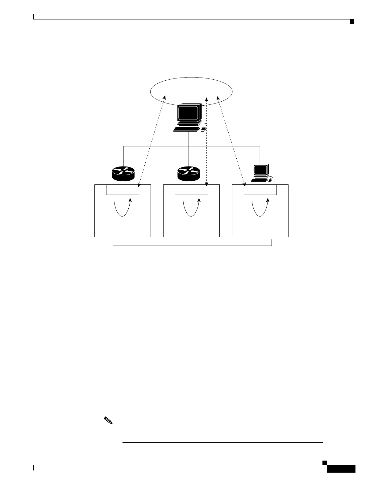
Figure 1 illustrates the relationship between the managed devices, the agent, and the NMS.
Figure 1 An SNMP-Managed Network
About Basic SNMP Message Types and Commands
Management
Entity
NMS
Agent
Management
Database
Agent
Management
Database
Managed Devices
Agent
Management
Database
About Basic SNMP Message Types and Commands
There are t hr ee b asi c SN M P m essage types :
—NMS-initiated requests used by an NMS to monitor managed devices. The NMS examines
Get
different variables that are ma inta ined by managed device s.
—NMS-initiated commands used by an NMS to control managed devices. The NMS changes
Set
the values of variables stored w ithi n m ana ged d evices.
—Agent-initiated messages sent from a managed device, which reports events to the NMS.
Trap
The Cisco IOS generates SNMP traps for many distinct netw ork con ditions. Th rough SNMP trap s,
the Network Operations Center (NOC) is notified of network events, such as:
35640
Link up/down changes
`
Configuration changes
`
Temperature thresholds
`
CPU overloads
`
Note
For a list of Cisco-supported SNMP trap s, go to
http://www.cisco.com/public/mibs/traps/
Basic Dial NMS Implementation Guide
#
Page 16
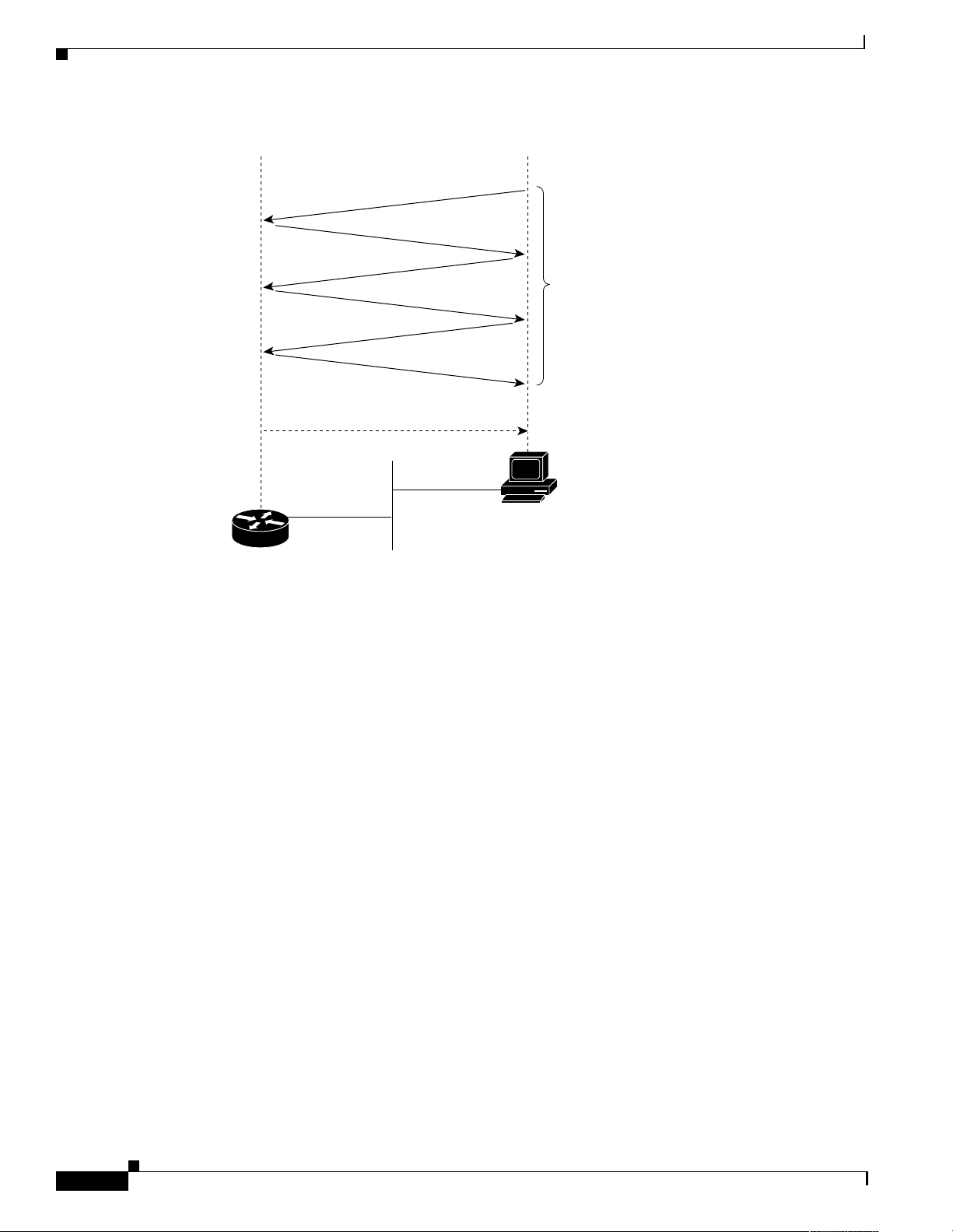
What are SNMP MIBs?
Overview of Basic SNMP Building Blocks
Figure 2 SNMP Event Interactions Between the NMS and the Agent
Get request
Response
Get next
Response
Get next
Response
Trap (agent initiated)
NMS
initiated
NMS
Agent
(Cisco IOS device)
What are SNMP MIBs?
A Management In fo rma tion Ba se (MIB ):
Presents a collection of information that is organized hierarchically.
Is accessed by using a network-managemen t protocol, suc h as SNMP.
References managed obje cts and obje ct ident ifiers.
Managed object
instances (variables). Two types of managed objects exist:
Scalar objects—Define a single object instance.
Tabular objects—Define multiple-related object instances that are grouped together in MIB tables.
Object identi f ier
is depicted as a tree with a nameless root. The levels of the tree are assigned by different organizations
and vendors.
—A characteris tic of a mana ged de vice. Mana ged object s referen ce one or more o bject
(or object I D)—Identif ies a managed object in the MIB h ierarch y . T he MIB hierarchy
26095
$
Basic Dial NMS Implementation Guide
Page 17

Overview of Basic SNMP Building Blocks
ccitt (0)
…
………
iso (1) iso-ccitt (2)
registrationauthority (1)
standard (0)
dod (6)
…
member-
body (2)
identified-
organization (3)
mgmt (2)directory (1) experimental (3) private (4) security (5) snmpV2 (6)
internet (1)
…
mib-2 (1) enterprise (1)
cisco (9)……
………
…
……
temporary
variables (3)
…… …
Apple Talk (3)
atForward (4)
Novell (3) VINES (4) Chassis (5)DECnet (1) XNS (2)
…
…
…
…
…
atBcastin (3)
atLocal (2)
atInput (1)
…
…
…
…
…
…
24187
Figure 3 The MIB Tree and Its Various Hierarchies
What are SNMP MIBs?
As shown in Figure 3, top-level MIB object IDs b elo ng to different sta ndard s o rganizations w hile
low-level object IDs are allocated by associated organizations . Vendor s define private branches tha t
include managed obje cts for pro ducts. N on standa rd MIBs are t ypicall y in the experim ental bra nch.
A managed object has these unique identities:
The object name
—For example, iso.iden tified-organi zat ion. dod .int erne t. private.enterpr i se.ci sco .
temporary variables.Ap pleTalk.atInput
or
The equivalent object descriptor
—For example, 1.3.6.1.4. 1.9 .3 .3.1.
Basic Dial NMS Implementation Guide
%
Page 18

What is SNMPv1?
SNMP must account for an d adjust to inco mpatibi lities betwe en man aged devices. Different computers
use different data-representation techniques, which can compromise the ability of SNMP to exchange
information betwee n manage d devices.
What is SNMPv1?
SNMPv1 is the initial implementation of the SNMP protocol and is described in RFC 1157
(http://www.ietf.org/rfc/rfc1157).
SNMPv1:
Functions within the specifications of t he Structur e of Manag ement Infor mation (SM I).
Operates over protocols s uch a s U ser D atagr am Pro toc ol ( UDP) , Interne t Pr otoc ol ( IP) , OSI
Connectionless Network Serv ice (CLNS) , AppleTalk Datagram-Delivery Protocol (DDP),
and Novell In ter net Packet E xchan ge (I PX).
Is the de facto network-manageme nt prot ocol in the Int ernet comm unity.
The SMI defines the rules for describing mana gement informat ion by using Abstrac t Syntax Notati on
One (ASN.1). The SNM Pv1 SMI is de fined in R FC 1 155 ( http ://ww w.ietf.org/rfc/rfc1155). Th e SMI
makes three specifications:
ASN.1 data types
SMI-specific data types
SNMP MIB table s
Overview of Basic SNMP Building Blocks
SNMPv1 and ASN1 Data Types
The SNMPv1 SMI specifies that all managed objects must have a subset of associated ASN.1 data types.
Three ASN.1 data types are required:
—Serves as the object identifier (object ID).
Name
Syntax
of the ASN.1 sy ntax definitio ns.
Encoding
of data items for transmission over the network.
—Defines the data type of the object (for example, integer or string). The SMI uses a subset
—Describes how information associated with a managed object is formatted as a series
SNMPv1 and SMI-Specific Data Types
The SNMPv1 SMI spec ifies the u se of ma ny SM I-sp ecific dat a t ypes, whi ch ar e divided in to t wo
categories:
Simple data types
Integers—A signed int eger i n the rang e of -2,1 47, 483 ,64 8 to 2 ,14 7,483, 64 7 .
`
Octet strings—Ordered se quences of zer o to 65,535 oc tets.
`
Object IDs— Come from the set of all object identifiers allocated according to the rules
`
specified in ASN.1.
—Including these three ty pe s:
&
Basic Dial NMS Implementation Guide
Page 19

Overview of Basic SNMP Building Blocks
What is SNMPv2?
Application-wide data types
Network addresses—Repre sent addr es ses from a prot ocol famil y. SNMPv1 supports only
`
32-bit IP addres ses.
Counters—Nonnegative integers that increase until they reach a maximum value; then, the
`
integers return to zero. In SNMPv1, a 32-bit counter size is specified.
Gauges—Nonnegative integers that can increase or decrease but retain the maximum value
`
reached.
Time ticks—A hundredth of a second since some event.
`
Opaques—An arbitr ar y e ncodi ng tha t is u sed to pa ss arbi tra ry infor mat ion s tr ings t hat d o n ot
`
conform to the strict data typing used by the SMI.
Integers—Signed integer-valued information . This da ta type re defines the integer data type,
`
which has arbitrary precision in ASN.1 but bounded precision in the SMI.
Unsigned integers—Unsigned integer-valued information that is useful when values are always
`
nonnegative. This data type redefines the integer data type, whic h has arbitr ary prec ision in
ASN.1 but bounded precision in the SMI.
The SNMPv1 SMI defines structured ta ble s that are used to gro up the inst an ces of a t abular objec t (an
object that contains multiple variables). Tables contain zero or more rows that are indexed to allow
SNMP to retrieve or alter an entire row with a single
SNMPv1 Protocol Operations
—Including these seven types:
Get, GetNext
, or
command.
Set
SNMP is a simple requ est-r espon se pro toc ol. Th e NMS issue s a req ue st, an d m an aged devices return
responses. This be havior is impl eme nte d by usin g o ne of f our p rotoc ol ope rati ons:
—Used by the NMS to retrieve the value of one or more object instances from an agent. If the
Get
agent responding to the Get operation cannot provide values for all the object instances in a list, the
agent does not provide any values.
GetNext
an agent.
—Used by the NMS to set the values of object instances within an agent.
Set
—Used by agents to asynchronously inform the NMS of a significant event.
Trap
What is SNMPv2?
SNMPv2 is an improved version of SNMPv1. Originally, SNMPv2 was published as a set of proposed
Internet standards in 1993; currently, it is a Draft Standard. As with SNMPv1, SNMPv2 functions
within the specifications of the SMI. SNMPv2 offers many improvements to SNMPv1, including
additional protocol opera tion s.
—Used by the NMS to retrie v e the v al ue of the ne xt objec t instance in a table or list within
Basic Dial NMS Implementation Guide
'
Page 20

About SNMP Management
SNMPv2 and SMI
The SMI defines the rules for describing ma nagement informa tion by using ASN.1.
RFC 1902 (http://www.ietf.org/rfc/rfc1902) describes the SNMPv2 SMI and enhances the SNMPv1
SMI-specific data types by including:
Bit strings
Network addresses
addresses, but SNMPv2 can support other t ypes of addre sses too.
Counters
integers return to zero. In SNMPv1, a 32-bit counter size is specified. In SNMPv2, 32-bit and 64-bit
counters are defined.
SMI Information Modules
The SNMPv2 SMI spec ifies info rm at ion mo dule s, w hic h in cl ude a g rou p o f r ela ted definitions. T hree
types of SMI information modules exist:
MIB modules
Compliance s tatem ent s
must conform to a standard.
Capability statements
respect to a MIB group. An NMS can ad just its beha vior to w ards age nts according to the capabili ty
statements associated with each agent.
Overview of Basic SNMP Building Blocks
—Comprise zero or more named bits that specify a value.
—Represent an address from a protocol family. SNMPv1 supports 32-bit IP
—Non-negative integers that increase until they reach a maximum value; then, the
—Contain definitions of interrel ated mana ged object s.
—Provide a systematic way to describe a gro up of manag ed object s that
—Used to indicate the precise level of support that an agent claims with
SNMPv2 Protocol Operations
The Get, GetNex t, an d Set o p er ation s u s ed in SNMPv 1 ar e e x ac tly th e same as those used in SN MPv 2.
SNMPv2, however, adds and enhances protocol operations. The SN MPv2 trap operation, for example,
serves the same fun ctio n as the o ne u sed i n SNM Pv1 . H owever, a different message f orm at i s us ed.
SNMPv2 also defines two new protocol operations:
GetBulk
table. GetBulk fills a response message with as much of the requested data as fits.
Inform
agent responding to GetBulk operations cannot provide values for all the variables in a list, the
agent provides partial results.
—Used by the NMS to ef ficiently retrieve large blocks of data, such a s multip le r ows in a
—Allows one NMS t o s e nd tr ap info r ma tio n to another NMS and rec eive a response. If the
About SNMP Management
SNMP is a distributed-management protocol. A system can operate exclusively as an NMS or an agent,
or a system can pe rf or m th e funct ion s o f b ot h.
When a system operates as both an NMS and an agent, another NMS can require the system to:
Query managed devices and provide a summar y of the info rmat ion lear ned.
Report locally stored manage ment info rmation.
Basic Dial NMS Implementation Guide
Page 21

Overview of Basic SNMP Building Blocks
About SNMP Security
SNMP lacks authentication capabilities, which results in a variety of security threats:
Masquerading
assuming the identity of an authorized management entity.
Modification of information
an authorized entity, so the message results in unauthorized accounting management or
configuration management ope rations.
Message sequence and timing modifications
delays, or copies and lat er replay s a messag e genera ted by an autho rized ent ity.
Disclosure
The ent ity can a lso le a rn of no tifiab le events by monit oring exch an ges be t wee n ma na gers an d
agents.
—Results when an unauthorized entity extracts values stored in managed objects.
About SNMP Security
—An unauthorized enti ty attempt ing to perfor m manageme nt opera tions by
—An unauthorized entity attempting to alter a message generated by
—Occurs when an unauthorized entity reorders,
Note
Because SNMP doe s n ot i mpl em ent aut hen tica tion, m any vendors d o not i m ple ment
operations, which reduce SNMP to a monitoring facility.
Set
Basic Dial NMS Implementation Guide
Page 22

About SNMP Security
Overview of Basic SNMP Building Blocks
Basic Dial NMS Implementation Guide
Page 23
Network Design for a Dial NMS Case Study
38198
POP #1
POP #2
PSTN
Internet
Redundancy
Remote modem
users
Firewall
NOC
Firewall
Backbone
router
Backbone
router
Intranet
WAN
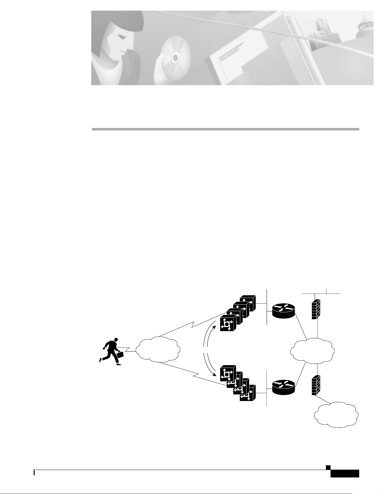
Introduction to the Case Study
This case study describes:
How one Internet service provid er (ISP) desi gns, impl ement s, and ope rates a di al network
management system (NMS) for a dial Internet access service (DIAS).
How to implement dial NMS protocols, applications, and other utilities.
THEnet is an ISP in Austin, Texas that wants to develop a dial NMS and integrate it with its existing
Network Operations Cente r (NOC). THEnet h as two dial point- of-pres ences (POP s) that provide
dial-up services for the fo llowing types of cu stomers :
Residential subscribers
Corporations who outsource their dial-up services and want to avoid the overhead of operating their
own dia l PO P.
Figure 4 THEnet Operates Two POPs from One NOC
Basic Dial NMS Implementation Guide
!
Page 24

Benefits of a Dial NMS
All remote modem users share a common pool of modem resources. Users can dial in to either POP .
The dial POPs are redundant. If one POP loses service, traffic is re-routed to the other POP.
Describing how traffic is re-routed is outside the scope of this case study, and the diagrams in the
case study show simplified IP paths only.
THEnet uses this model to identif y the differen t function al area s of the dia l NMS:
= Fault management
F
= Configuration manage ment
C
= Accounting ma na geme nt
A
= Performance management
P
= Security manage ment
S
A dial NMS provides the FCA PS man agem ent func tions f or a D IAS.
Benefits of a Dial NMS
A dial NMS:
Increases network availability
Improves end-user satisfaction by improving service perf ormance
Provides fault-isolation capabilities, which improves fault-analysis information
Reduces network support cost s
Enables capacity plannni ng
Enables security improvements
Provides accounting (for example, billing and chargeback)
Processes important connection events and alarms for statistical analysis
Provides performance-reporting capabilities for a dial Internet access service
Enables standar diz ed sof t ware re lea se s ( for exam ple , software version s a nd c onfigurati on files)
Addresses the perception problems that are commonly associated with dial access networks
Network Design for a Dial NMS Case Study
"
Basic Dial NMS Implementation Guide
Page 25

Network Design for a Dial NMS Case Study
Dial NMS Planning Questionnaire
This planning questionnaire describes information that is essential for creating a dial NMS service
definition. A questionnaire helps network engineers make accurate design decisions and consider
alternative solutions. The network engineers at THEnet answered the design questions as shown in
Table 2.
Table 2 Network Design Questions and Answers
Network Design Questions
What types of services does you r network provide? Dial Internet access services
How many dial POP sites are you managing? Two sites in Austin, Texas
What types of ne twork servic es wil l the D IAS supp ort?
(Network manageme nt is ba sed on cust om er r equ ireme nts .)
What is the user-growth projection for the next 5 years?
3 months = Current depl oyment req uire ment .
1 year = Current design plan requirement.
5 years = Future scalability plan requirement.
What is the use r-to-line rati o duri ng busy hours? 10:1
What level of service must you gua rant ee to you r cus to mers? Guaranteed up time
Do you have redundant connections to th e Intern et? Yes
Do you have redundant conn ec ti ons t o the NOC ? Yes
What existing servers do you have available in the NOC?
What SNMP framework mana geme nt sy stem d o y ou want t o
use?
What element management system do you use for collecting and
managing syslog?
Do you have a prefer red p l atfo rm and ope rat ing syste m fo r
monitoring the network?
What type of network access servers will you use? Cisco AS5800s
Do you have a staff of UNIX experts? Yes
Dial NMS Planning Questionnaire
THEnet
Answers
(V.90 analog modem ser vices)
Residential subscriber
services
Corporate-outsour cing
services
3 months—50,000 us er s
1 year—100,000 us er s
5 years—1 million users
SNMP management server
Syslog server
AAA server
Database se rver
HP OpenView (HPOV)
CiscoWorks 2000 Resource
Manager Essentials
(CW2000 RME)
Yes
Sun Sparc, Solaris 2.6
Basic Dial NMS Implementation Guide
#
Page 26

Dial NMS Planning Questionnaire
Table 2 Network Design Questions and Answers (continued)
Network Design Questions
Do you provide reports for any service level commitments with
your customers? If yes, what management systems will you use?
Identify the types of users who require network managemen t
reports.
What types of repo rts d o y ou provide?
What format do the ma nagers want to view the reports in? HTML web pages and
Who will monitor the manageme nt system s? The network operations staff
How will network operators be notified of network problems? By sending e-mail to their pagers
For fault and performance management purposes, do you need to
provide call detail records?
What securit y pro to co ls do yo u use fo r au th ent ica tio n,
authorization, and accounting (AAA)?
What dial NMS fre eware do yo u p lan to use ? MRTG, UCD-SNMP, Linux, and
What software tools do you plan to develop internall y?
Do you plan to build and maintain customized scripts? Yes
Network Design for a Dial NMS Case Study
THEnet
Answers
Yes
Multi Router Traffic Grapher
(MRTG)
Custom-based AAA
accounting tools and da tabase
query tools
Network managers
Network operators
Network engineers
Help desk operators
Corporations who outsourc e
their dial-up serv ice
End users
Periodic performanc e report s
Billing reports
Security reports
Router operations reports
High-priority syslog rep orts
online graphs
Yes
Disconnect cause codes and retrain
counters must be inspected.
RADIUS for the remo te
modem users
TACACS+ for the router
administrators in the N OC
Apache
Log File Ro tator
Device Navigator
Modem Call Record Viewer
Web-based management
Wa r Diale r for per formanc e
testing (optional)
$
Basic Dial NMS Implementation Guide
Page 27

Network Design for a Dial NMS Case Study
Dial NMS Service Definition
A service definition is a statement that describes required services for a network design.
The dial NMS service definition determin ed for TH Enet i s based on:
The answers p rovided i n Table 2
The FCAPS model
Fault management
`
Configuration manageme nt
`
Accounting manageme nt
`
Performance management
`
Security management
`
Table 3 Dial NMS Service Definition for THEnet
FCAPS
Function Service Requirements and Ways to Collect M anagement Data
Fault
management
SNMP—Use UCD-SNMP and HPOV to explore the SNMP Management
Information Bases (MIBs) and create the SNMP framework for the
dial NMS.
The Cisco IOS com ma nd-l ine inte rfac e (C LI )—Troubleshoot n etwor k
connectivity problems by collecting robust network statistics.
For example, use the following commands:
`
Dial NMS Service Definition
show controller t1
`
show isdn status
`
debug ppp negotiation
`
show isdn service
`
debug ppp error
`
debug isdn events
`
debug isdn q921
`
debug isdn q931
Syslog—Troubleshoot and isolate faults in the network by collecting
syslog data and modem c all records. Impo rtant sy slog me ssages will be
e-mailed daily to the oper ations staff.
Log file management—Collect and archive syslog data from network
access servers.
Web-based manage m ent—N avigate d evices a nd enab l e HT TP acc ess t o
the CLI.
AAA—Collect accounting disconnect ca use codes and view authentic ation
and authorization failures.
Basic Dial NMS Implementation Guide
%
Page 28

Dial NMS Service Definition
Table 3 Dial NMS Service Definition for THEnet (continued)
FCAPS
Function Service Requirements and Ways to Collect Management Data
Configuration
management
Network Design for a Dial NMS Case Study
SNMP—Use CW2000 RME to ar chive configuration files, manage
Cisco IOS images, determine how much memo ry is installed, a nd discov er
which boot ROMs are present.
CLI—Inspect and mo dify Cisc o IOS c onfigura tion files an d im ages.
For example, use the following commands:
Accounting
management
`
show version
`
show running
`
show modem version
AAA authentication—Control access to the routers.
AAA authorization—Limit CLI command access to router administrators
on a per group basis. Authorization is also used for limiting network
service assignments, such as static IP addresses and access lists.
AAA accounting—Monitor which configuration changes are made to the
routers and identif y who is making the changes. Authenticated usernames
also appear in syslog.
Effective IP address management— Man age al l assign ed IP subne ts by
using a DNS server and the applicatio n Cisco Network Registrar.
Web-based manage ment —N avigate d evices a nd enab l e HT TP acc ess t o
the CLI.
Send accounting in forma tion t o a data base tha t is ac cessibl e by Sta ndard
Query Language (S QL) . Arch ive user-accounti ng dat a fo r b i lling a nd
auditing purposes.
Syslog—Collect basic accounting information by using modem call
records.
CLI—Collect accounting statistics. For example, use the following
commands:
&
Basic Dial NMS Implementation Guide
`
show interface accounting
`
show isdn history
`
show controller t1 call-counters
`
show modem log
`
show modem summary
`
show modem call-stats
Page 29

Network Design for a Dial NMS Case Study
Table 3 Dial NMS Service Definition for THEnet (continued)
FCAPS
Function Service Requirements and Ways to Collect M anagement Data
Performance
management
Security
management
Dial NMS Service Definition
SNMP—For the initial installation, use MRTG to monitor key Object
Identifications (OIDs) in the device MIBs. In the future, use commercial
software applica tions tha t coll ect ma ss s cale m anag ement d ata s tream s for
large numbers of access servers.
CLI—Monitor the pe rform ance of the acce ss ser vers . Fo r e xampl e, use th e
following commands:
`
show modem operational-status
`
show modem connect-speeds
`
show modem summary
`
show modem call-stats
Web-based manage m ent—N avigate d evices a nd enab l e HT TP acc ess t o
the CLI.
War Dialer—Test remote client PCs by using a free client simulator.
Authenticate, authorize, and account for dial access clients (modem users)
in each POP by using RADIUS.
Authenticate, authorize , and ac co unt f or router ad m in istra tors in th e NO C
by using TACACS+.
Review the AAA service security logs.
Review the AAA server database by using SQL queries.
CLI—Inspect security information. For example, use the following
commands:
`
show snmp group
`
show access-lists
`
show location
`
show tacacs
`
show radius statistics
`
show logging
Web-based manage m ent—N avigate d evices a nd enab l e HT TP acc ess t o
the CLI.
Basic Dial NMS Implementation Guide
'
Page 30
Network Topology
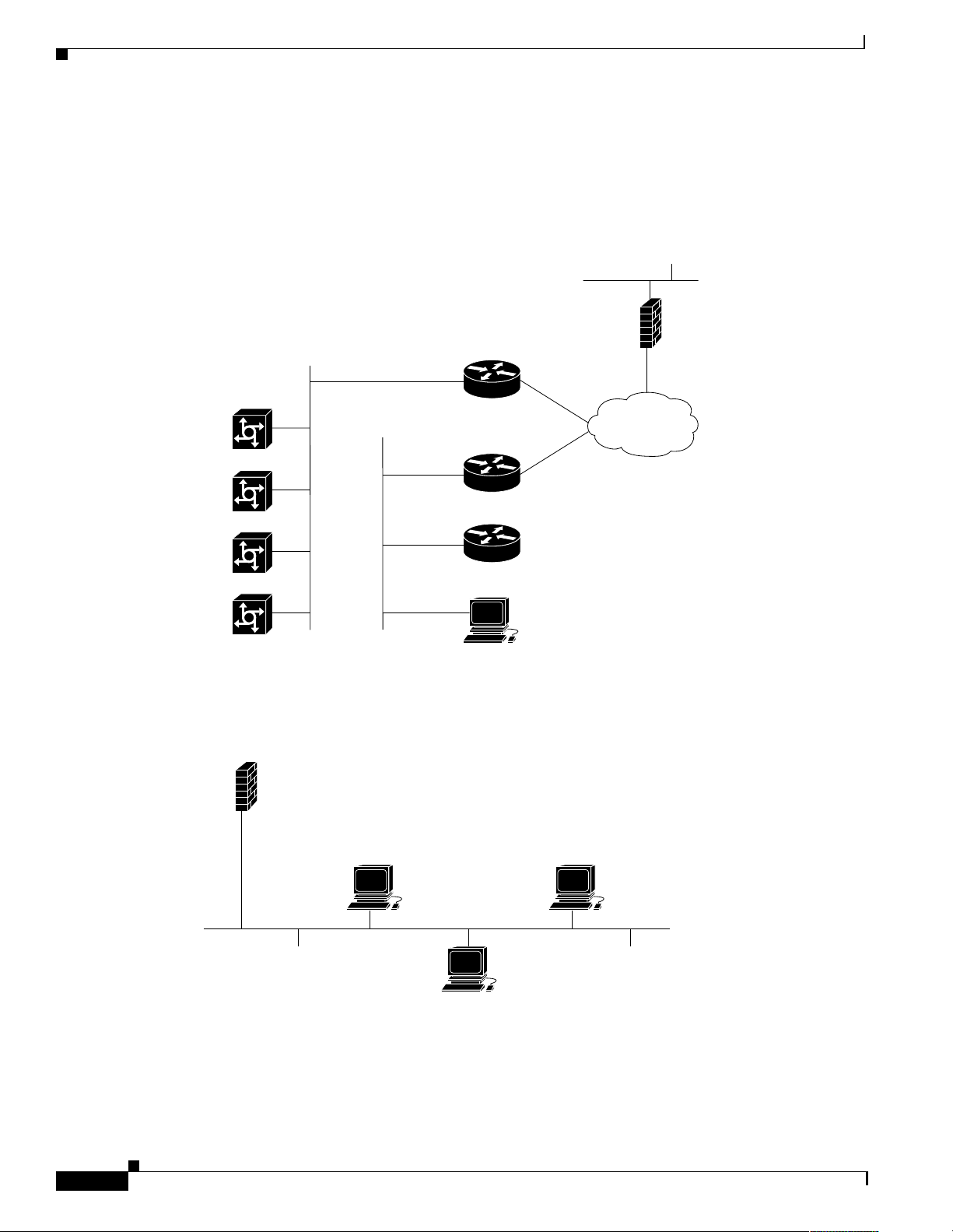
Network Topology
Based on the dial NMS service de finition in Table 3, the network engineers a t THEne t defined
the network topology for the POPs and NOC.
Figure 5 Network Topology for One POP
Cisco AS5800
access servers
Network Design for a Dial NMS Case Study
NOC
Firewall
Backbone
router
Intranet
WAN
Backbone
router
Cisco 2511
OOB console server
AAA server
Data
(for remote client users)
Control
38197
An intranet WAN connects the two POPs together and routes traffic to the Internet. The NOC collects
management data from both POPs.
Figure 6 Network Topology for the NOC
Cisco PIX
firewall
HP OpenView
CW 2000
UCD-SNMP
MRTG
38199
!
AAA
An important design issue to consider is where to send syslog data. If syslog data is sent back to a
central site NOC, the syslog data must trav el across WAN links. Estimate and monitor ho w much syslog
data is generate d by each PO P and the imp act o n the WAN links. Modem call records can a dd a
significant amount of traffic to syslo g d ata.
Basic Dial NMS Implementation Guide
Page 31

Network Design for a Dial NMS Case Study
In this case study , THEnet initially sends syslog data across WAN links to the NOC. The WAN links are
designed to support a large network capacity in a metropolitan area. Collecting syslog locally in each
POP is a future design consideration.
Hardware Requirements
T o design the dial NMS for the two POPs and the NOC, the network engineers at THEnet defined these
hardware requiremen ts:
Table 4 Hardware Description for Two POPs and the NOC
Hardware Purpose
4 Cisco AS5800
access servers
2 backbone
gateways
2 Cisco 2511 OOB
console servers
3 AAA servers One server in each POP to authenticate, authorize, and account for dial access
Two access servers in each POP to provide access in to the Internet from the
PSTN. Cisco IOS Release 12.0(7)T is installed in each access server.
Enables management data streams to enter the NOC.
Routes traffic to the intranet WAN and the Internet.
Accesses the cons ole po rts i n the C i sco A S5800s by using out-o f- ban d (OO B)
management lines.
clients by using RADIUS.
Hardware Requirements
One server in the NOC to authenticate, authorize, and account for router
administrators by using TACACS+.
1 Cisco PIX firewal l Protects the NOC by f ilterin g the de vic es that can acc ess ma nageme nt service s,
such as TACAC S+, R ADIUS, syslog, and SNMP.
3 Sun Ultra 10
Operates the dial NMS inside the NOC. Solaris version 2.6 is used.
workstations
The following capacity-planning calculations were made to determine the number of required lines and
Cisco AS5800s for the next five years.
Basic parameters:
There are 23 available bearer channels per PRI line
There are 28 PRI lines per T3 card (644 channels)
Each Cisco AS580 0 has t wo T3 car ds
There are 12 88 available bear er c han nel s per d ua l T3 C isc o A S580 0
Table 5 Capacity-Planning Matrix for the Line and Chassis Requirements
Time
3 months
1 year
5 years
Busy Hour
Ratio
10:1 50,000 5000 5000 lines / 1288 = 3.88 chassi s 4 AS5800s
10:1 100,000 10,000 10,000 lines / 1288 = 7.76 chassis 8 AS5800s
10:1 1,000,000 100,000 100,000 lines / 1288 = 7 7.6 4 chassi s 78 AS5800s
Users
Required
Lines
Required Chassis Calculation
AS5800s
Required
Basic Dial NMS Implementation Guide
!
Page 32

Software Requirements
These calculations i n Table 5 are bas ed on a PRI sy stem int egratio n—no t a syste m si gnal ling 7 ( SS7)
integration.
For each POP site, also plan for the following elements:
Power, space, and cooling for each Cisco AS5800
Required number of AAA servers
Required number of Cisco 2511s (OOB ports)
WAN link ca pa city
Software Requirements
T o desi gn the dial NMS inside the NOC, the ne twork engine ers at THEnet identi fie d these software an d
management system requi rements:
Table 6 Dial NMS Software and Management System Requirements
Software and Management Systems Purpose
UCD-SNMP Uses CLI-bas ed SN MP freeware t o explore the SNMP MIBs
Multi Router Traffic Grapher
(MRTG), version 2.8.12
Web-based management Manages a network by using light-weight NMS tools (LWT).
Network Design for a Dial NMS Case Study
and OIDs that are useful for operating a dial network.
Monitors and graphs the traffic load on the network.
A LWT is light on:
Budget
Staff support
Course requirements
GUI requirements
!
HP OpenView (HPOV) Network
Node Manager Release 5.0
CiscoWorks 2000, maintenance
release 2
Resource Manager E sse ntials
(RME), version 2.2
Basic Dial NMS Implementation Guide
THEnet requires the following LWTs:
Device Navigator—A web page that links network devices
together.
Cisco IOS Command Cente r—A web pa ge tha t p rovides
HTTP access to the CLI.
Log File Rotator—A freeware script that archives, sorts,
and deletes syslogs.
Modem Call Record Viewer—A tool that enables you to
view modem records and syslogs on a web page.
Creates the SNMP framework for the dial NMS and identifies
what is breaking in the network.
Archives configuration files, upgrades the Cisco IOS,
determines how m uch memory is instal led, and disco v ers what
boot ROMs are present.
You can install HPOV and CW2000 RME on the sa me Sun
workstation—without conflicts.
Page 33

Network Design for a Dial NMS Case Study
35229
POP #1
172.21.0.0/16
POP #2
172.22.0.0/16
Device ID
IP pool
Device ID
IP pool
PSTN
Modems
Clients
Internet
Firewall
NOC
Firewall
Access
Access
Intranet
WAN
Table 6 Dial NMS Software and Management System Requirements (continued)
Software and Management Systems Purpose
CiscoSecure Un ix, versi on 2.3(3 )
War Dialer Runs performance tests by using a di al simul ator and
client PCs.
Configuration Design Parameters
Before THEnet can implement and operate the dial NMS, several design parameters must be defined by
the network engineers and ope rat ors.
Configuration Design Parameters
Authenticates, authorizes, and accounts for dial access
clients in each POP by using RADIUS.
Authenticates, authorizes, and accounts for router
administrators in the NOC by using TACACS+.
Uses AAA accounting records to collect performance
data, fault data, and track rout er configurat ion chan ges.
Each dial POP requires enough IP address space for the POP to grow to its maximum size. For THEnet,
each POP must support up to 50,000 lines. Therefore, an entire class B network is initially assigned to
each POP.
Figure 7 IP Subnetting Diagram for the THEnet
To simpl ify IP addr es s m anagem ent, ea ch POP u ses a simil ar IP su bnet ting plan .
Basic Dial NMS Implementation Guide
!!
Page 34

Configuration Design Parameters
Table 7 IP Subnetting Plan for POP #1 and POP #2
Network Name Assigned IP Subnet Description
POP #1 172.21.0.0/16 Class B IP subnet assigned to POP #1.
POP #2 172.22.0.0/16 Class B IP subnet assigned to POP #2.
NOC 172.23.10.0/24 Class C IP subnet assigned to the NOC.
Access 172.21.101.0/24
DeviceID 172.21.10.0/24
172.21.102.0/24
172.22.101.0/24
172.22.102.0/24
172.22.10.0/24
Network Design for a Dial NMS Case Study
Primary and secondary class C access Ethernet subnets.
All the access de vices i n each POP are d irectly connect ed
to these subnets.
Identifi es each Cisco IOS dev ice with a unique, fix ed, and
stable loopback IP addre ss for network ma nageme nt
purposes.
One IP address is assigned to the loopback 0 interface of
each Cisco IOS device.
One IP address block is used to simpli fy IP-secu rity
filtering at the NOC. This technique protects the NOC
from devices that should not access manag ement
services, such a s TACACS+, RADIUS, sys log, a nd
SNMP.
IP pool 172.21.103.0/24
172.21.104.0/22
172.22.103.0/24
172.22.104.0/22
Hosts a pool of IP addr esses for the di al ac cess cli ents
with modems.
This IP assignment provides 1280 IP ad dresses to each
POP. The ac cess s ervers create th e IP routes to suppor t
the IP pools.
Few IP routes are summarized to the backbone instead of
advertising 1280 host r oute s.
Table 8 SNMP Community Strings Used at THEnet
Community Strings Purpose
5urf5h0p Assigns a read-only (RO) communi ty s tri ng t o ena ble SNM P po llin g and
SNMP get requests.
5crapmeta1 Assigns a read-write (RW) community string to enab le router conf iguratio n
changes.
!"
Caution
Do not use “public” or “private” strings, which are well known in the industry, are
common hardware defaults, and invite attacks from hackers—regardless if you use filters.
To maximize security, choose community strings that are not associated with your
personal life or company.
Basic Dial NMS Implementation Guide
Page 35

Network Design for a Dial NMS Case Study
The information in Table 9 is posted and maintained on web-based management pages. Easy access to
this information reduces network down time.
Table 9 T1 Support Management Information at THEnet
Implementation and Operation Tasks
T1 Dial-in Number Circuit ID
512-111-2222 72ABCA047006-001PT ABC 512-555-1212
512-333-4444 72ABCA047006-002PT DEF 512 -55 5-1212
Implementation and Operation Tasks
THEnet implements and operates the dial NMS in two phases:
Phase A
and light-weight NMS tools:
Phase B
management systems:
—Exploring and setting up basic dial NMS functions by using free m anagement software
Task 1—Enabling SNMP in a Cisco IOS Device
Ta sk 2— Exploring SN MP Capabiliti es by Using UCD-SNMP
Task 3—Using MRTG to Monitor and Graph Traffic Loads
Ta sk 4—Using Sysl og, NTP, and Modem Call Record s to Isolate and Troubleshoot Faults
Task 5—Setting Up a Web Portal for the Dial NMS
—Monitoring and maintaining basic dial NMS functions by using commerciall y available
Ta sk 6 —Ma nagi ng I P A dd resses by Us ing D NS
Support
Contract
Contact Phone
Number
Task 7—Using HP OpenView to Create the SNMP Framework
Ta sk 8—Usin g CiscoWorks 2000 Resource Manager Essentia ls
Note
Providing information for i ntegratin g h igh- end m a nagem ent sy stems i s
beyond the scope of t his ca se st ud y.
The examples in this docume nt are taken from a Sun Microsyst ems workstat ion runni ng Solaru s 2.6.
Some commands and filename s may vary sligh tly on o th er U nix syste ms, su ch a s L inux and H P UX .
Basic Dial NMS Implementation Guide
!#
Page 36

Implementation and Operation Tasks
Network Design for a Dial NMS Case Study
!$
Basic Dial NMS Implementation Guide
Page 37

Dial MIBs and OIDs Used in the Case Study
This section describes the MIBs and OIDs used to manage the dial Internet access service in the
case study.
See the following tables and choose the variables you wan t to use in your network. Explore the OIDs
and determine w het her to po l l a nd gra ph the r esul ts on a r egular ba sis.
To explore the MIBs and OIDs, use UCD-SNMP. For more information, see the
“Task 2— Exploring SNMP Capabilities by Using UCD-SNMP” section on page 45.
To graph the trending statistics for a specific OID, use Multi Router Traffic Grapher (MRTG).
For more information, see the “Task 3—Using MRT G to Monitor and Graph T raf fic Lo ads” section
on page 53.
Caution
Be cautious when polling network elements. Polling OIDs that retrieve large amounts of
data can cause CPU problems on a Cisco IOS device. For example, do not get the ARP
table, walk large p ortions of a MIB tree, poll the wrong OID too freq uently , or get statistics
that have an entry for every interface. For example, a Cisco 7200 may have 10 interfaces;
whereas, a Cisco A S580 0 may h ave 3,000 int erfaces.
Table 10 MIBs to Consider Using for the Dial NMS
Dial Related System Management MIB II / Interfaces
CISCO-POP-MGMT-MIB
1
OLD-CISCO-CHASSIS RFC1213-MIB
CISCO-MODEM-MGMT-MIB CISCO-MEMORY-POOL-MIB IF-MIB
CISCO-VPDN-MGMT-MIB CISCO-SYSTEM-MIB C ISCO-CAS-IF-MIB
CISCO-AAA-SESSION-MIB CISCO-FLASH-MIB CISCO-ISDN-MIB
CISCO-AAA-SERVER-MIB CISCO-CONFIG-MAN-MIB
CISCO-CALL-HISTORY-MIB CISCO-PROCESS-MIB
CISCO-DIAL-CONTROL-MIB
CISCO-CALL-RES OUR CE- P OOL -MIB
1. This MIB was enhanced in Cisco IOS Release 12.1(2)XH and later releases.
For a complete list of available Cisco MIBs, go to
http://www.cisco.com/public/sw-center/netmgmt/cmtk/mibs.shtml
For a list of Cisco-supported traps, go to http://www.cisco.com/public/mibs/traps
Basic Dial NMS Implementation Guide
!%
Page 38

Dial MIBs and OIDs Used in the Case Study
For more information abou t other NMS en hancem ents for dial, see
AAA Enhancements for the Cisc o AS5300 and Ci sco AS5800
Call Tracker plus ISDN and
at
http://www.cisco.com/univercd/cc/td/doc/product/software/ios121/121newft/121limit/121x/121xh
/121xh_2/dt_cltrk.ht m
Note
To pro t ect a n etwor k ac cess ser ver f rom over pol li ng, u se t he SN MP get bulk fe atu re .
It’s available in SNMP v2 in CISCO-BULK-FILE-MIB.
Ta ble 11 and Table 12 identify usefu l O IDs a nd variables wi thin se le cte d MI Bs f rom Table 10.
Equivalent Cisco IOS commands are shown wherever applicable. Sometimes data is more clearly
inspected by using OIDs and a graphing tool instead of CLI commands.
To see the c omplet e struct ure of the CISCO -POP- MGM T-MIB and CISCO-MODEM-MGMT-MIB,
go to the fo llowing URLs :
CISCO-POP-MGMT-MIB
http://www.cisco.com/univercd/cc/td/doc/cisintwk/intsolns/dialnms/popmgt.txt
CISCO-MODEM-MGMT-MIB
http://www.cisco.com/univercd/cc/td/doc/cisintwk/intsolns/dialnms/modemmgt.txt
Table 11 Description of CISCO-POP-MGMT-MIB
Equivalent Cisco IOS
Description OID
Number of analog cal ls connec ted cpmISDNCfgBCha nInUs eForAn
Command
show modem summary
alog
.1.3.6.1.4.1 .9.10 .1 9.1 .1. 2
Number of active DS0s in use cpmActiveDS0s
.1.3.6.1.4.1 .9.10 .1 9.1 .1. 4
show controllers t1
call-coun t e rs
show isdn memory
(See the
number of call control
blocks, CCBs, in the
command output. )
Total call count per DS0
cpmCallCount
.1.3.6.1.4.1.9.10.19.1.1.1.1.7
Total time in use for each DS0 cpmTimeInUse
.1.3.6.1.4.1.9.10.19.1.1.1.1.8
Total octets received on a DS0 cpmInOctets
show controllers t1
call-coun t e rs
show controllers t1
call-coun t e rs
None available
!&
Total octets transmitted on a DS0 cpmOutOctets
Total packets received on a DS0 cpmInPackets
Basic Dial NMS Implementation Guide
.1.3.6.1.4.1.9.10.19.1.1.1.1.9
None available
.1.3.6.1.4.1.9.10.19.1.1.1.1.10
None available
.1.3.6.1.4.1.9.10.19.1.1.1.1.11
Page 39

Dial MIBs and OIDs Used in the Case Study
Table 11 Description of CISCO-POP-MGMT-MIB (continued)
Description OID
Total packets transmitted on a DS0 cpmOutPackets
Number of active PPP calls cpmPPPCalls
Number of active V120 calls cpmV120Calls
Number of active V110 calls cpmV110Calls
Maximum number of DS 0s used
simultaneously
Type of call curre ntly connected to
each DS0
.1.3.6.1.4.1.9.10.19.1.1.1.1.12
.1.3.6.1.4.1 .9.10 .1 9.1 .1. 5
.1.3.6.1.4.1 .9.10 .1 9.1 .1. 6
.1.3.6.1.4.1 .9.10 .1 9.1 .1. 7
cpmActiveDS0sHighWaterMark
.1.3.6.1.4.1 .9.10 .1 9.1 .1. 8
cpmDS0CallType
.1.3.6.1.4.1.9.10.19.1.1.1.1.5
Equivalent Cisco IOS
Command
None available
None available
None available
None available
show controllers t1
call-co unters
None available
Table 12 Description of CISCO-MODEM-MGMT-MIB
Variable Description OID
Modems available to take calls
cmSystemModemsAvailable
.1.3.6.1.4.1.9.9.47.1.1.7
Average call duration for each
modem
Number of times each modem
failed to answer
Number of times each modem
failed to train up successfully
Number of times each modem
successfully tra ined up
cmCallDuration
.1.3.6.1.4.1.9.9.47.1.3.1.1.9
cmRingNoAnswers
.1.3.6.1.4.1.9.9.47.1.3.3.1.1
cmIncomingConn ect ionFailur es
.1.3.6.1.4.1.9.9.47.1.3.3.1.2
cmIncomingConn ecti onCo mple ti
ons
.1.3.6.1.4.1.9.9.47.1.3.3.1.3
Current TX speed for all the
modems
Current RX speed for all the
modems
List of us er s c ur re ntl y co nnect e d
and authenticated
Call durations for cu rrentl y
connected and authenticated users
cmTXRate
.1.3.6.1.4.1.9.9.47.1.3.1.1.14
cmRXRate
.1.3.6.1.4.1.9.9.47.1.3.1.1.15
cpmActiveUserID
.1.3.6.1.4.1.9.10.19.1.3.1.1.3
cpmActiveCallDuration
.1.3.6.1.4.1.9.10.19.1.3.1.1.8
Equivalent Cisco IOS
Command
show modem summary
show modem
show modem
show modem
show modem
show modem
connect-speeds
show modem
connect-speeds
show caller
show caller
Basic Dial NMS Implementation Guide
!'
Page 40

Dial MIBs and OIDs Used in the Case Study
Table 12 Description of CISCO-MODEM-MGMT-MIB (continued)
Variable Description OID
List of user C LI Ds cpmActiveRemotePhoneNumbe r
.1.3.6.1.4.1.9.10.19.1.3.1.1.2
List of called DNIS phone numbers cpmActiveLocalPhoneNumber
.1.3.6.1.4.1.9.10.19.1.3.1.1.13
List of TTY interfaces in use cpmActiveTTYNumber
.1.3.6.1.4.1.9.10.19.1.3.1.1.14
List of which use r i s usin g wh ich
modem slot
List of which use r i s usin g wh ich
modem port
List of which IP addresses are
currently in use
cpmActiveModemSlot
.1.3.6.1.4.1.9.10.19.1.3.1.1.6
cpmActiveModemPort
.1.3.6.1.4.1.9.10.19.1.3.1.1.7
cpmActiveUserIpAddr
.1.3.6.1.4.1.9.10.19.1.3.1.1.4
Equivalent Cisco IOS
Command
show caller ip
show isdn history
show caller ip
show caller ip
show caller user
show caller user
show caller ip
"
Basic Dial NMS Implementation Guide
Page 41

Task 1Enabling SNMP in a Cisco IOS Device
About Enabling SNMP
In this case study:
Each Cisco IOS device is identified by a fixed and stable loopback IP address for network
management purposes. T he IP addr ess functi ons as an device ID.
One block of loopback IP addresses is used to simplify IP-security filtering at the NOC. This
technique protects the N OC from devices that shoul d not acce ss manageme nt servi ces, such as
TACACS+, RADIUS, syslog, and SNMP.
The dial NMS environment interfaces with SNMP through these applications:
UCD-SNMP
`
SNMP Commander
`
Multi-Router Traffic Grapher (MRTG)
`
HP OpenView (HPOV)
`
Cisco Works 2000 Reso urce Ma nage r E ssenti als (CW 2000 R ME )
`
Caution
Avoid using well-known commun ity st ring s, such as “publ ic ,” “ private,” or “cisc o.”
These s trings are e asily guesse d and leave your device open to mal icious at tacks or
inadvertent access. To further enhance SNM P security , a pply access list s to the commun ity
strings.
Basic Dial NMS Implementation Guide
"
Page 42

About Enabling SNMP
Enabling SNMP
To en able SNM P on a Cisco IO S device in the network, follow these step s.
Task 1Enabling SNMP in a Cisco IOS Device
Step 1
Step 2
Note
In some software re leas es, th e comm ands
snmp-server packetsize
are enabled by default.
snmp-server engineID local
and
To use Loop ba ck 0 for device mana geme nt a nd set SNM P t raps to u se t hat IP a ddr ess, e nte r the
following commands. This configur ati on al so elimi n ate s the ne ed to change IP ad dresse s if a di fferent
interface is used to send traps.
!
interface Loopback0
ip address 172.21.10.1 255.255.255.255
!
!
snmp-server trap-source Loopback0
!
T o enable a basic SNMP configuration, enter the following commands. See Table 13 for descriptions of
each command.
snmp-server community 5urf5h0p RO
snmp-server community 5crapmeta1 RW
snmp-server location Lake Travis (Austin) Dial POP
snmp-server contact net-admin@aurora.the.net
snmp-server enable traps
snmp host 172.23.10.1 traps SNMPv1
Table 13 SNMP Command Descriptions
Command Purpose
snmp-server community 5urf5h0p RO
Assigns a read only (RO) communi ty string. O nly get
requests (queri es ) ca n be pe rf orme d.
The RO community string i n this exampl e ( 5ur f5h 0p)
allows Get requests b ut no Set operations. The N MS and the
managed device must reference th e sam e com mun ity str in g.
snmp-server community 5crapmeta1 RW
Assigns a read write (RW) community string. SNMP
applications require RW access for Set operations.
The RW community string in this example (5crapmeta1)
enables write access to OID values. For example, you can
shut down an interface, downlo ad a configur ation file, or
change a password.
snmp-server location Lake Travis
(Austin) Dial POP
snmp-server contact admin
net-admin@aurora.the.net
Specifies the location of the device for administ rative
purposes.
Specifies a contact name to notify whenever a MIB problem
occurs.
"
Basic Dial NMS Implementation Guide
Page 43

Task 1Enabling SNMP in a Cisco IOS Device
Table 13 SNMP Command Descriptions (continued)
Command Purpose
snmp-server enable traps
snmp host 172.23.10.1 traps SNMPv1
About Enabling SNMP
Enables traps for unsolicited notif ications for conf iguration
changes, environmental variables, and critical device
conditions.
This command e na ble s 14 + ot her co mm an ds for di stinc t
types of SNMP traps. Edit this command list to include only
the traps that are used by your network environment.
Identifies the host destinat ion for the traps. T raps ar e sent in
the SNMP v1 format in this case study.
Basic Dial NMS Implementation Guide
"!
Page 44

About Enabling SNMP
Task 1Enabling SNMP in a Cisco IOS Device
""
Basic Dial NMS Implementation Guide
Page 45

Task 2 Exploring SNMP Capabilities by Using
UCD-SNMP
About Using UCD-SNMP
Researching and identifying which functions are available in SNMP are part of building a dial NMS
environment. In this case study, UCD-SNMP, an opensource freeware application that allows access to
SNMP functions from a command line interface (CLI), is used to explore the capabilities of SNMP.
There are many benefits to usin g UCD-SNM P.
You can:
Gain a fundamenta l u nderst andi ng o f h ow SNMP fu nc tions a nd prot ocol s work in a dia l a ccess
environment. This knowledge provides a sol id f oun dat ion for us ing a uto mated a nd GUI -base d
SNMP applications.
Learn how to use a low-level troubl e shoo tin g capa bility in the event that other SNMP applications
produce questionable results.
Poll any OID and verify SNMP agent responses.
Use stable and rel iabl e CLI co mmand s. UCD -SNM P is unob struct ed by GUI funct ional ity.
Explore and r es earc h MI B co nt en t.
Discover what functions a re available to ma nage a C i sco IO S device.
Create customi zed scripts an d tool s.
For this case study, the dial engineers at THEnet created a tool called SNMP Commander. The tool
aided the MIB research task by en abling dial engineers to b uild web-based object identification (OIDs)
bookmarks, which they c ou ld g o t o w it hout usi ng a keyboar d.
By using UCD-SNMP and SNMP Commander, the dial engineers at THEnet identified which items the
commercial NMS applications would monitor within the network operations center (NOC).
Basic Dial NMS Implementation Guide
"#
Page 46

Task 2 Exploring SNMP Capabilities by Using UCD-SNMP
About Using UCD-SNMP
Installing UCD-SNMP and Downloading Cisco MIBs
To install UCD-SNMP and download MIBs from the Cisco FTP site, follow these steps.
Step 1
Step 2
Step 3
Step 4
Note
You can also download individual MIBs from
http://www.cisco.com/public/sw-center/netmgmt/cmtk/mibs.shtml
Go to http://ucd-snmp.ucdavis.edu
Download, compile , and in stal l UCD- SNM P. In this case study, the UCD-SNM P comm ands ar e
installed in the /usr/local/bin directory.
From the Cisco FT P site , download th e MIBs int o th e /usr/ loca l/sh are/ sn mp/m ibs d ire ct or y on your
Solaris workstation. By using the following Unix commands, you can copy the entire bundl ed v1 MIB
tar file from ftp.ci sco. co m.
cd /usr/local/share/snmp/mibs
ftp ftp.cisco.com
cd /pub/mibs/v1
bin
get v1.tar.gz
exit
Decompress and untar the files in the /usr/local/share/snmp/mibs directory:
gzip -d v1.tar.gz
tar -xvf v1.tar
Note
There are many MIBs in the tar file that you may not use. Regardless, Cisco
recommends you keep a ll the MI Bs o n file to s uppo rt your evolving networ k
needs.
Exploring SNMP MIBs for Dial Netwo rks
To explore the MIBs for a Cisco IO S device by using SNMP CLI commands, foll ow the steps in this
section. Poll OID variables by using the commands
"$
Note
Step 1
To determine the last restart reason for the router, enter the
In the following example, the restart reason is “reload.”
onionring:~$ snmpget travis-nas-01.the.net 5urf5h0p .1.3.6.1.4.1.9.2.1.2.0
Counter32 (is a reserved word): At line 6 in /usr/local/share/snmp/mibs/SNMPv2-S
MI-V1SMI.my
Gauge32 (is a reserved word): At line 7 in /usr/local/share/snmp/mibs/SNMPv2-SMI
-V1SMI.my
Integer32 (is a reserved word): At line 8 in /usr/local/share/snmp/mibs/SNMPv2-S
MI-V1SMI.my
Did not find 'mib-2' in module RFC1213-MIB (/usr/local/share/snmp/mibs/IANAifTyp
e-MIB-V1SMI.my)
Basic Dial NMS Implementation Guide
This section assumes you alrea dy have a basic understandi ng of UCD-SNM P
and know how to use it s C LI comm a nds.
snmpget, snmpwalk
snmpget
command and th e re levant OID.
, and
snmptable
.
Page 47

Task 2 Exploring SNMP Capabilities by Using UCD-SNMP
enterprises.9.2.1.2.0 = "reload"
If SNMP-parsing err ors a re g ener ate d, sup pre ss them by appe nd ing
command. Standa rd output is tagged as 1. Error output is tag ged as 2.
onionring:~$ snmpget travis-nas-01.the.net 5urf5h0p .1.3.6.1.4.1.9.2.1.2.0 2> /dev/null
enterprises.9.2.1.2.0 = "reload"
onionring:~$
2>/dev/null
About Using UCD-SNMP
to the end of the
Step 2
Step 3
Step 4
Note
Check the syst em up ti me by enteri ng th e
onionring:~$ snmpget travis-nas-01.the.net 5urf5h0p .1.3.6.1.2.1.system.sysUpTime.0 2>
/dev/null
system.sysUpTime.0 = Timeticks: (45450609) 5 days, 6:15:06.09
onionring:~$
If no response is returned by the SNMP agent, allow error messages to print to the
screen by removing th e
2>/dev/null
argument.
snmpget
command and sysUpTime OID:
To gat her basi c configurati on manage ment in format ion about t he Cisco IOS device, enter th e
snmpwalk
onionring:~$ snmpwalk travis-nas-01.the.net 5urf5h0p system 2> /dev/null
system.sysDescr.0 = "Cisco Internetwork Operating System Software ..IOS (tm) 5800
Software (C5800-P4-M), Version 12.1(2a)T1, RELEASE SOFTWARE (fc2)..Copyright
(c) 1986-2000 by cisco Systems, Inc...Compiled Mon 12-Jun-00 23:13 by ccai"
system.sysObjectID.0 = OID: enterprises.9.1.188
system.sysUpTime.0 = Timeticks: (45492606) 5 days, 6:22:06.06
system.sysContact.0 = "net-admin@aurora.the.net"
system.sysName.0 = "travis-nas-01.the.net"
system.sysLocation.0 = "Lake Travis (Austin) Dial POP"
system.sysServices.0 = 78
system.8.0 = Timeticks: (0) 0:00:00.00
onionring:~$
Change the OID environmental prefix by entering the commands
command and the system OID.
prefix
and
export prefix
. This step
reduces the number of key strokes you must enter at the command line.
onionring:~$ snmpget travis-nas-01.the.net 5urf5h0p .1.3.6.1.4.1.9.2.1.2.0 2> /
dev/null
enterprises.9.2.1.2.0 = "reload"
onionring:~$ PREFIX=.1.3.6.1.4.1.9
onionring:~$ export PREFIX
onionring:~$ snmpget travis-nas-01.the.net 5urf5h0p 2.1.2.0 2> /dev/null
enterprises.9.2.1.2.0 = "reload"
onionring:~$
The UCD-SNMP application attaches a prefix to the requested variable unless it is fully qualified (for
example, unless the variable starts with a period “.”). By default, the prefix points to the MIB-II node
.1.3.6.1.2.1 location. The Cisco enterprises prefix points to .1.3.6.1.4.1.9
Step 5
Inspect the IP address entr y table by entering t he
onionring:~$ snmptable travis-nas-01.the.net 5urf5h0p ip.ipAddrTable 2> /dev/null
SNMP table: ip.ipAddrTable.ipAddrEntry
ipAdEntAddr ipAdEntIfIndex ipAdEntNetMask ipAdEntBcastAddr ipAdEntReasmMaxSize
172.21.10.1 351 255.255.255.255 1 18024
172.21.101.20 289 255.255.255.0 1 18024
onionring:~$
snmptable
command and ipAddrTable OID:
Basic Dial NMS Implementation Guide
"%
Page 48

About Using UCD-SNMP
Task 2 Exploring SNMP Capabilities by Using UCD-SNMP
Step 6
Step 7
Poll the interfaces table and redirect the output to a text file by entering the
snmptable
command and
ifTable OID:
onionring:~$ snmptable travis-nas-01.the.net 5urf5h0p interfaces.ifTable
> /export/home/www/travis-nas-01_ifTable.txt
onionring:~$
Note
Inspect the contents of t he interfa ces table b y entering the
Do not forget the space between > and
/export
command. In the following Cisco AS5800
cat
example, notice the interface descr iptions (ifDescr) and types (ifType). There is one PPP and DS0 entry
for each serial int erfac e.
onionring:~$ cat /export/home/www/travis-nas-01_ifTable.txt
SNMP table: interfaces.ifTable.ifEntry
ifIndex ifDescr ifType ifMtu ifSpeed ........
1 "Async1/2/00" other 1500 9000
2 "Async1/2/01" other 1500 9000
3 "Async1/2/02" other 1500 9000
.
.
.
.
289 "FastEthernet0/0/0" ethernetCsmacd 1500 100000000
290 "Null0" other 1500 4294967295
291 "T1 1/0/0" ds1 ? ?
292 "T1 1/0/1" ds1 ? ?
.
.
.
.
301 "T1 1/0/10" ds1 ? ?
302 "T1 1/0/11" ds1 ? ?
303 "Serial1/0/0:0" propPointToPointSerial 1500 64000
304 "Serial1/0/0:1" propPointToPointSerial 1500 64000
.
.
.
.
326 "Serial1/0/0:23" lapd 1500 64000
327 "Serial1/0/0:23-Signaling" isdn 1500 64000
328 "Serial1/0/0:0-Bearer Channel" ds0 ? ?
329 "Serial1/0/0:1-Bearer Channel" ds0 ? ?
.
.
.
.
350 "Serial1/0/0:22-Bearer Channel" ds0 ? ?
351 "Loopback0" softwareLoopback 15144294967295
"&
To view the complete, unabridged output for this example, go to
http://www.cisco.com/univercd/cc/td/doc/cisintwk/intsolns/dialnms/iftable.txt
Basic Dial NMS Implementation Guide
Page 49

Task 2 Exploring SNMP Capabilities by Using UCD-SNMP
About SNMP Commander
The dial engineers at TH Enet creat ed a tool call ed SNM P Comma nder tha t:
Provides web-based access to UCD -SNM P C LI c omma nds.
Builds web-based OI D bo okm ar ks, w hic h e nabl e y ou to g o to OID s witho ut u si ng a keyboard.
Aids the MIB exploration and NMS design task s.
By using SNMP Comm an der and a w e b browser, you can:
Create URL links for the network st aff and help desk.
Identify target OIDs you want to graph by using MRTG.
Inspect thresholds and events to monitor by using other NMS systems.
The following two com pon en ts wor k t o geth er to cr eat e SN M P Co mm an der:
snmpcmds.dat
This file is read by the snmpcmds.pl script.
For the source code, go to
http://www.cisco.com/univercd/cc/td/doc/cisintwk/intsolns/dialnms/snmpdat.txt
snmpcmds.pl
creating multiple instances of the original script and altering the data file descriptor.
—A comma separated var iables file, wh ich includes a list of SNMP CLI command s.
—A script that loads and reads a data file. You can use additional data files by
About SNMP Commander
For the source code, go to
http://www.cisco.com/univercd/cc/td/doc/cisintwk/intsolns/dialnms/snmppl.txt
Setting Up SNMP Commander
To set up SNMP Commander, follow these steps:
Step 1
Step 2
Step 3
From CCO, download snmpcm ds. dat and snm pcmds. pl
Customize the files for your environment. When you find useful OIDs, enter them in the snmpcmds.dat
file and use the web-based form of the script to research the MIBs. The web tool functions like an SNMP
OID bookmarker.
Test SNMP Commander by using a web browser:
a.
Select an SNMP command and OID.
b.
Select an SNMP agent (Cisco IOS device).
c.
Click
Submit
d.
Inspect the pro gr am a nd quer y m es sag es.
.
Basic Dial NMS Implementation Guide
"'
Page 50

About SNMP Commander
Task 2 Exploring SNMP Capabilities by Using UCD-SNMP
Figure 8 SNMP Commander Tool
#
Basic Dial NMS Implementation Guide
Page 51

Task 2 Exploring SNMP Capabilities by Using UCD-SNMP
Figure 9 Polling Results from the table cpmActiveCallSummaryTable Command
About SNMP Commander
Basic Dial NMS Implementation Guide
#
Page 52

About SNMP Commander
Task 2 Exploring SNMP Capabilities by Using UCD-SNMP
#
Basic Dial NMS Implementation Guide
Page 53

Task 3Using MRTG to Monitor and Graph
35193
Polling OID
Returning OID valves
Cisco
IOS
devices
MRTG
Traffic Loads
About MRTG
Multi Router Traffic Grapher (MRTG) is a free performance management app licat ion for Uni x that
monitors SNMP statistics from any SNMP capable device on your network and performs the following
functions:
Captures, stores, and graphically presents SNMP data. By default, a web page with four graphs per
MIB object (OID) is created by MRTG. The graphs show the variation of MIB data over time.
Runs from the cront ab. Every five minutes, a cro n job r uns M RTG to query a u ser-con figured li st
of OIDs and network devices. After each data collection cycle, the MRTG perl script posts updated
graphs to a web page.
Efficiently compresses and ar chives data samp les to crea te graphs .
Enables you to determine if trendin g data is useful for monitor ing your environment be fore you
inv est in costly ne tw ork p erf orma nce softw ar e. If tr en ding da ta is cr iti cal to manage your network,
it may be necessary to purchase a commercial network performance package, such as Concord
Network Health. H owever, you may find that MRTG is all you n ee d.
Figure 10 MRTG Polls for OIDs; OID Values that Are Returned to MRTG
Basic Dial NMS Implementation Guide
#!
Page 54

About Selecting Dial OIDs
For each OID referenced in the configuration file, MRTG creates the following graphs:
Daily graph
Weekly graph
Monthly graph
Yearly graph
—5 minute average data points with approxim ately 33 hou rs of data prese nted.
—30 minute average data points with ap proxima tely 8 days of data prese nted.
—2 hour average data points with approximately 5 weeks of data presented.
—1 day average data points with approxi mate ly 1 year of dat a present ed.
To quickly create images by using the GD graphics library, go to http://www.boutell.com/gd
About Selecting Dial OIDs
To select which dial OIDs to query when monitoring dial-up activity, see the OIDs listed in the
following tables:
Circuit utilization OIDs (Table 14)
Modem information OID s (Table 15)
User information OIDs (Table 16)
Task 3Using MRTG to Monitor and Graph Traffic Loads
Caution
Be cautious when polling network elements. Polling OIDs that retrieve large amounts of
data can cause CPU problems on a Cisco IOS device. For example, do not get the ARP
table, walk large p ortions of a MIB tree, poll the wrong OID too freq uently , or get statistics
that have an entry for every interface. For example, a Cisco 7200 may have 10 interfaces;
whereas, a Cisco A S580 0 ma y h ave 3,000 inter faces.
In this case study, the tools UCD-SNMP a nd SNMP Com mande r were use d to inspe ct an d u nde rstand
the MIBs. Based on this research , the netw ork engineer s at THEnet id entif ied the OIDs in th e follo wing
tables to program in to MRTG.
To see the c omplet e struct ure of the CISCO -POP- MGM T-MIB and CISCO-MODEM-MGMT-MIB,
go to the fo llowing URLs :
CISCO-POP-MGMT-MIB
http://www.cisco.com/univercd/cc/td/doc/cisintwk/intsolns/dialnms/popmgt.txt
CISCO-MODEM-MGMT-MIB
http://www.cisco.com/univercd/cc/td/doc/cisintwk/intsolns/dialnms/modemmgt.txt
Table 14 Circuit Utilization OIDs
Vari ab le
Analog calls CISCO-POP-MGMT-MIB
Base MIB and OID Description
The number of analog calls connected.
1.3.6.1.4.1.9.10 .1 9.1.1. 2
Active DS0s CISCO-POP-MGMT-MIB
The total number of calls connected.
1.3.6.1.4.1.9.10 .1 9.1.1. 4
Call count CISCO-POP-MGMT-MIB
1.3.6.1.4.1.9.10 .1 9.1.1. 1.1. 7
The number of calls that have occupied a
specific DS0.
#"
Basic Dial NMS Implementation Guide
Page 55

Task 3Using MRTG to Monitor and Graph Traffic Loads
Table 14 Circuit Utilization OIDs (continued)
About Selecting Dial OIDs
Vari ab le
Base MIB and OID Description
Time in use CISCO-POP-MGMT-MIB
1.3.6.1.4.1.9.10 .1 9.1.1. 1.1. 8
PPP calls CISCO-POP-MGMT-MIB
1.3.6.1.4.1.9.10 .1 9.1.1. 5
DS0 high
water mark
Table 15 Modem Information OIDs
Vari ab le
Modems
available
Average call
duration
CISCO-POP-MGMT-MIB
1.3.6.1.4.1.9.10 .1 9.1.1. 8
Base MIB and OID Description
CISCO-MODEM-MGMT-MIB
1.3.6.1.4.1.9.9.47 .1.1. 7
CISCO-MODEM-MGMT-MIB
1.3.6.1.4.1.9.9.47 .1. 3.1.1 .9
No answers CISCO-MODEM-MGM T-MIB
1.3.6.1.4.1.9.9.47 .1. 3.3.1 .1
Failed Train CISCO- MODEM -MGM T-MIB
1.3.6.1.4.1.9.9.47 .1. 3.3.1 .2
Successful
train
CISCO-MODEM-MGMT-MIB
1.3.6.1.4.1.9.9.47 .1. 3.3.1 .3
TX speed CISCO-MOD EM- MG MT-MIB
1.3.6.1.4.1.9.9.47 .1. 3.1.1 .1 4
RX speed CISCO-MODEM-MGMT-MIB
1.3.6.1.4.1.9.9.47 .1. 3.1.1 .1 5
The time for each DS0.
The number of active PPP calls.
The maximum nu mb er of D S0s ever used
simultaneously.
The number of modems curre ntly available to
take calls.
The aver age call duration for ea ch modem in the
NAS.
The number of calls not answered by a modem.
The number of modem calls that failed to train
up.
It’s normal behavior for most modems t o not
have a 100 percent success rate.
The number of modem calls that successfully
trained up.
It’s normal for most modems to not have a 100
percent success rate.
The current transmit speed (TX) of all the
modems in the NAS.
If a modem does n o t h ave an active call, zer o is
returned.
The current receive speed (RX) of all the
modems in the NAS.
If a modem does n o t h ave an active call, zer o is
returned.
Basic Dial NMS Implementation Guide
##
Page 56

How to Inspect and Interpret Data
Table 16 User Information OIDs
Task 3Using MRTG to Monitor and Graph Traffic Loads
Variable Base MIB and OID
Active user ID
CISCO-MODEM-MGMT-MIB
.1.3.6.1.4.1.9.10.19.1.3.1.1.3
Active call duration CISCO-MODEM-MGMT-MIB
.1.3.6.1.4.1.9.10.19.1.3.1.1.8
User CLID CISCO-MODEM-MGMT-MIB
.1.3.6.1.4.1.9.10.19.1.3.1.1.2
DNIS phone number CISCO-MODEM-MGMT-MIB
.1.3.6.1.4.1.9.10.19.1.3.1.1.13
Active TTY CISCO-MODEM-MGMT-MIB
.1.3.6.1.4.1.9.10.19.1.3.1.1.14
Active modem slot CISCO-MODEM-MGMT-MIB
.1.3.6.1.4.1.9.10.19.1.3.1.1.6
Active modem port CISCO-MODEM-MGMT-MIB
.1.3.6.1.4.1.9.10.19.1.3.1.1.7
Active user IP CISCO-MODEM-MGMT-MIB
.1.3.6.1.4.1.9.10.19.1.3.1.1.4
Description
List of users currently connected
and authenticated.
Call durations for currently
connected and auth enticat ed users.
List of user Caller IDs (CLID).
List of called Dialed Number
Information Servi ce (DN IS) ph one
numbers.
List of asynchronous terminal lines
(TTY) in use.
List of which user is using which
modem slot.
List of which user is using which
modem port.
List of which IP addresses are
currently in use.
How to Inspect and Interpret Data
Internet users spend ap pro xima tely 80 pe r cent o f thei r time r eadi ng i nf or matio n—no t downloading
data. Modem traffic is very limited on a per user basis. People cannot read as fast as modems ca n
download. Therefore, watch for the foll owing types of trends and perform ance data on the acce ss
servers:
PPP sessions in use.
DS0s in use.
Modem calls that have been rejected.
The number of calls com ing in to the access server and at what tim e.
Spikes or dips in total calls connected outside the normal call pattern.
Long-term trends that may mean that you ne ed to upgra de compone nts in your network.
Throughput that has been reduced to unacceptable levels (potential bottlenecks).
For disaster recovery purposes, when fail over events and routing swaps occur, look for drops in the
primary data path and jumps in th e backup pat h.
The utilization of the IP backbone, such as a Frame Relay link or Ethernet campus.
#$
Basic Dial NMS Implementation Guide
Page 57
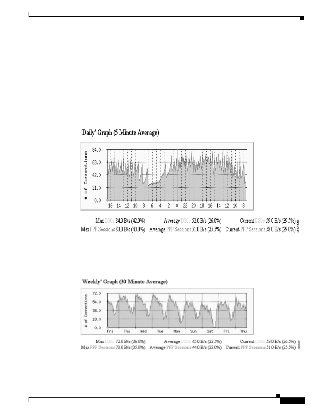
Task 3Using MRTG to Monitor and Graph Traffic Loads
The Connection Success Rate (CSR) is an important metric for tracking and measuring the stability of
a dial service. The CSR is defined by the number of modems t hat successf ully train up and go in to
connected state. In addition to the CSR, you must track and analyze additional areas. For example,
SNMP MIBs can be used to measure the success rate for items such as PPP, AAA, and IP negotiation.
To collect the CSR service level counters, inspect the connection success and failure rate by using
modem OIDs or the
show modem
preferred method to collect these counters. SNMP can scale to support large numbers of access servers.
The following graphs show the DS0s and PPP sessions in use for 70,000 modem users calling in to a
dial-up service at a large university. The graphs are taken from one Cisco AS5300 in a large dial-up
modem pool.
Figure 11 Daily Graph: DS0s and PPP Sessions in Use
How to Inspect and Interpret Data
Cisco IOS command. SNMP, rather than the Cisco IOS CLI, is the
The jagged saw-tooth pattern at the top of the graph indicates a telephone-switch hunt group for the dial
lines passing by the access servers. A “jump up” occ urs each time the hunt group passes by a d ifferent
T1 line. For a hunt group that rotates in a round-robi n fashion, a jag ged saw-tooth pa ttern is nor mal.
Figure 12 Weekly Graph: DS0s and PPP Sessions in Use
Basic Dial NMS Implementation Guide
#%
Page 58
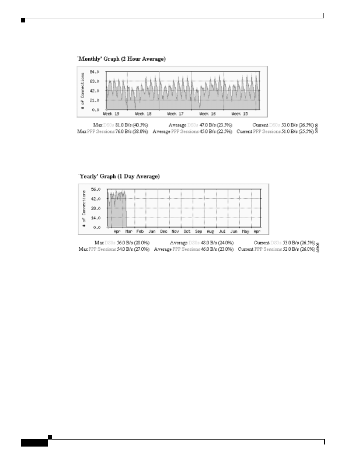
How to Inspect and Interpret Data
Figure 13 Monthly Graph: DS0s and PPP Sessions in Use
MRTG efficiently compresses and archives data to create graphs. For example, you can keep
information for an ent ire year on a se rver without using much disk spa ce.
Figure 14 Yearly Graph: DS0s and PPP Sessions in Use
Task 3Using MRTG to Monitor and Graph Traffic Loads
The configuration file used to crea te thes e grap hs is posted at
http://www.cisco.com/univercd/cc/td/doc/cisintwk/intsolns/dialnms/mrtg53.txt
Note the numeric OIDs in the configuration file.
#&
Basic Dial NMS Implementation Guide
Page 59

Task 3Using MRTG to Monitor and Graph Traffic Loads
Creating and Editing a Configuration File
Because dial interfaces normally go up and down as calls connect and disconnect, monitor counters
such as:
PPP sessions in use
DS0s in use
Modem calls that have been rejected
Depending on how the dial interfaces are used on a access server, different types of counters may not
be valuable to monitor, such as byte-packet counters on the interfaces in Table 17.
Table 17 Dial Interface Types on a Cisco AS5800
Interface Type Syntax Example
Asynchronous Asy nc1/ 2/00
B-channel serial Serial1/0/0:1
D-channel serial Ser ial1/0/0: 23
Group asynchrono us Group-Async0
T1/E1 controlle rs T1 1/0/0
How to Inspect and Interpret Data
Step 1
Step 2
Step 3
To enable MRTG to locate a device and poll it for network statistics, follow these steps:
Collect the hostname s, I P a ddress, and re ad only (RO) SNMP commu nity st rin gs fo r the d evices to be
monitored.
Download, compile, and install MRTG on to a Solaris workstation:
For the source code, go to http://ee-staff.ethz.ch/~oetiker/webtools/mrtg/pub/
For the documentation, see the section “Getting and Installing MRTG on a UNIX System” at
http://ee-staff.ethz.ch/~oetiker/webtools/mrtg/mrtg.html
Create a configuration file.
There are two basic ways to crea te the file:
Manually create it by using the MRTG files config.text and sample-mrtg.config. These files are in
the /mrtg/doc d ire ctor y.
or
Use the configurati on m aker ( cf gmaker ) i n t he /m rtg/ ru n d ire ctor y. MRTG creates a basic
configuration file for you. The default configuration file made with cfgmaker automatically polls
for a standard set of MIBs and pre -defined values.
Generic command sy ntax:
./cfgmaker communitystring@hostname-or-ipaddress >> outputfilename.cfg
Basic Dial NMS Implementation Guide
#'
Page 60

How to Inspect and Interpret Data
Example:
In the previous example:
Task 3Using MRTG to Monitor and Graph Traffic Loads
./cfgmaker 5urf5h0p@travis-nas-01 >> travis-nas-01.cfg
5urf5h0p
travis-nas-01
travis-nas-01.cfg
is the SNMP community string.
is the hostnam e of the m an aged device.
is the configuration file that MRTG reads each time it starts up.
Step 4
Note
If the domain n am e ser ver (D N S) is no t work ing, M RTG cannot use a host name .
You must use an IP a ddress instead .
By using a text editor, edit the configuration file (.cfg) to enable polling of dial variables and OIDs.
For a complete list of OIDs to poll, see the “About Selecting Dial OIDs” section on page 54.
The following configuration file is from a Cisco AS5 300. Thi s file can be used as a co nfiguration
template for your environment, but use yo ur own co mm unity st r ing, work dire cto ry, and device name.
The following defin itions are used in the example:
The RO community string is
The work direct or y is
The device name is
travis-nas-01
5urf5h0p
WorkDir: /export/home/www/mrtg/travis-nas-01/dial
An electronic copy of this template is available at
http://www.cisco.com/univercd/cc/td/doc/cisintwk/intsolns/dialnms/dialmrtg.txt
WorkDir: /export/home/www/mrtg/travis-nas-01/dial
# set defaults
Options[_]: growright
# make legends reflect these are call counters
YLegend[_]: Active Calls
ShortLegend[_]: calls
LegendI[_]: calls:
LegendO[_]: calls:
######################################################################
#----------------------------------------------------------------------------------------
-----# purpose: DS0s and PPP Sessions.
#----------------------------------------------------------------------------------------
-----Target[travis-nas-01_DS0PPP]:
1.3.6.1.4.1.9.10.19.1.1.4.0&1.3.6.1.4.1.9.10.19.1.1.5.0:5urf5h0p@travis-nas-01
MaxBytes1[travis-nas-01_DS0PPP]: 200
MaxBytes2[travis-nas-01_DS0PPP]: 200
Title[travis-nas-01_DS0PPP]: DS0s and PPP sessions in Use
PageTop[travis-nas-01_DS0PPP]: <H2>DS0s and PPP sessions in Use</H2>
<TABLE>
<TR><TD>Device:</TD><TD>travis-nas-01</TD></TR>
<TR><TD><a href="/mrtg/mrtg.html">HOME</a></TD></TR>
</TABLE>
Options[travis-nas-01_DS0PPP]: gauge
$
Basic Dial NMS Implementation Guide
Page 61

Task 3Using MRTG to Monitor and Graph Traffic Loads
#--------------------------------------------------------------------------------------# purpose: DS0s and Analog
#--------------------------------------------------------------------------------------Target[travis-nas-01_DS0ANALOG]:
1.3.6.1.4.1.9.10.19.1.1.4.0&1.3.6.1.4.1.9.10.19.1.1.2.0:5urf5h0p@travis-nas-01
MaxBytes1[travis-nas-01_DS0ANALOG]: 200
MaxBytes2[travis-nas-01_DS0ANALOG]: 200
Title[travis-nas-01_DS0ANALOG]: DS0s and Analog in Use
PageTop[travis-nas-01_DS0ANALOG]: <H2>DS0s and Analog in Use</H2>
<TABLE>
<TR><TD>Device:</TD><TD>travis-nas-01</TD></TR>
<TR><TD><a href="/mrtg/mrtg.html">HOME</a></TD></TR>
</TABLE>
Options[travis-nas-01_DS0ANALOG]: gauge
#----------------------------------------------------------------------------------------
-----# purpose: DS0s and SerialX:Y
#----------------------------------------------------------------------------------------
-----Target[travis-nas-01_DS0SERIAL]:
1.3.6.1.4.1.9.10.19.1.1.4.0&1.3.6.1.4.1.9.10.19.1.1.3.0:5urf5h0p@travis-nas-01
MaxBytes1[travis-nas-01_DS0SERIAL]: 200
MaxBytes2[travis-nas-01_DS0SERIAL]: 200
Title[travis-nas-01_DS0SERIAL]: DS0s and SerialX:Y in Use
PageTop[travis-nas-01_DS0SERIAL]: <H2>DS0s and SerialX:Y in Use</H2>
<TABLE>
<TR><TD>Device:</TD><TD>travis-nas-01</TD></TR>
<TR><TD><a href="/mrtg/mrtg.html">HOME</a></TD></TR>
</TABLE>
Options[travis-nas-01_DS0SERIAL]: gauge
How to Inspect and Interpret Data
#----------------------------------------------------------------------------------------
-----# purpose: DS0s and Sw56
#----------------------------------------------------------------------------------------
-----Target[travis-nas-01_DS0Sw56]:
1.3.6.1.4.1.9.10.19.1.1.4.0&1.3.6.1.4.1.9.10.19.1.1.10.0:5urf5h0p@travis-nas-01
MaxBytes1[travis-nas-01_DS0Sw56]: 200
MaxBytes2[travis-nas-01_DS0Sw56]: 200
Title[travis-nas-01_DS0Sw56]: DS0s and Sw56 in Use
PageTop[travis-nas-01_DS0Sw56]: <H2>DS0s and Sw56 in Use</H2>
<TABLE>
<TR><TD>Device:</TD><TD>travis-nas-01</TD></TR>
<TR><TD><a href="/mrtg/mrtg.html">HOME</a></TD></TR>
</TABLE>
Options[travis-nas-01_DS0Sw56]: gauge
#----------------------------------------------------------------------------------------
-----# purpose: cpmISDNCallsRejected and cpmModemCallsRejected
#----------------------------------------------------------------------------------------
-----Target[travis-nas-01_callrejects]:
1.3.6.1.4.1.9.10.19.1.2.1.0&1.3.6.1.4.1.9.10.19.1.2.2.0:5urf5h0p@travis-nas-01
MaxBytes1[travis-nas-01_callrejects]: 200
MaxBytes2[travis-nas-01_callrejects]: 200
Title[travis-nas-01_callrejects]: travis-nas-01 cpmISDNCallsRejected and
cpmModemCallsRejected
PageTop[travis-nas-01_callrejects]: <H2>cpmISDNCallsRejected and
cpmModemCallsRejected</H2>
<TABLE>
<TR><TD>Device:</TD><TD>travis-nas-01</TD></TR>
Basic Dial NMS Implementation Guide
$
Page 62

How to Inspect and Interpret Data
<TR><TD><a href="/mrtg/mrtg.html">HOME</a></TD></TR>
</TABLE>
#----------------------------------------------------------------------------------------
-----# purpose: cpmISDNCallsClearedAbnormally and cpmModemCallsClearedAbnormally
#----------------------------------------------------------------------------------------
-----Target[travis-nas-01_clearAbnormal]:
1.3.6.1.4.1.9.10.19.1.2.3.0&1.3.6.1.4.1.9.10.19.1.2.4.0:5urf5h0p@travis-nas-01
MaxBytes1[travis-nas-01_clearAbnormal]: 200
MaxBytes2[travis-nas-01_clearAbnormal]: 200
Title[travis-nas-01_clearAbnormal]: travis-nas-01 cpmISDNCallsClearedAbnormally and
cpmModemCallsClearedAbnormally
PageTop[travis-nas-01_clearAbnormal]: <H2>cpmISDNCallsClearedAbnormally and
cpmModemCallsClearedAbnormally</H2>
<TABLE>
<TR><TD>Device:</TD><TD>travis-nas-01</TD></TR>
<TR><TD><a href="/mrtg/mrtg.html">HOME</a></TD></TR>
</TABLE>
#----------------------------------------------------------------------------------------
-----# purpose: cpmISDNNoResource and cpmModemNoResource
#----------------------------------------------------------------------------------------
-----Target[travis-nas-01_callNoResource]:
1.3.6.1.4.1.9.10.19.1.2.5.0&1.3.6.1.4.1.9.10.19.1.2.6.0:5urf5h0p@travis-nas-01
MaxBytes1[travis-nas-01_callNoResource]: 200
MaxBytes2[travis-nas-01_callNoResource]: 200
Title[travis-nas-01_callNoResource]: travis-nas-01 cpmISDNNoResource and
cpmModemNoResource
PageTop[travis-nas-01_callNoResource]: <H2>cpmISDNNoResource and cpmModemNoResource</H2>
<TABLE>
<TR><TD>Device:</TD><TD>travis-nas-01</TD></TR>
<TR><TD><a href="/mrtg/mrtg.html">HOME</a></TD></TR>
</TABLE>
#----------------------------------------------------------------------------------------
-----# purpose: cmSystemModemsInUse and cmSystemModemsAvailable
#----------------------------------------------------------------------------------------
-----Target[travis-nas-01_modemcount]:
1.3.6.1.4.1.9.9.47.1.1.6.0&1.3.6.1.4.1.9.9.47.1.1.7.0:5urf5h0p@travis-nas-01
MaxBytes1[travis-nas-01_modemcount]: 200
MaxBytes2[travis-nas-01_modemcount]: 200
Title[travis-nas-01_modemcount]: cmSystemModemsInUse and cmSystemModemsAvailable
PageTop[travis-nas-01_modemcount]: <H2>cmSystemModemsInUse and
cmSystemModemsAvailable</H2>
<TABLE>
<TR><TD>Device:</TD><TD>travis-nas-01</TD></TR>
<TR><TD><a href="/mrtg/mrtg.html">HOME</a></TD></TR>
</TABLE>
Options[travis-nas-01_modemcount]: gauge
Task 3Using MRTG to Monitor and Graph Traffic Loads
$
#----------------------------------------------------------------------------------------
-----# purpose: cvpdnTunnelTotal and cvpdnDeniedUsersTotal
#----------------------------------------------------------------------------------------
-----Target[travis-nas-01_vpdn_tunnelanddenied]:
1.3.6.1.4.1.9.10.24.1.1.1.0&1.3.6.1.4.1.9.10.24.1.1.3.0:5urf5h0p@travis-nas-01
MaxBytes1[travis-nas-01_vpdn_tunnelanddenied]: 200
Basic Dial NMS Implementation Guide
Page 63

Task 3Using MRTG to Monitor and Graph Traffic Loads
MaxBytes2[travis-nas-01_vpdn_tunnelanddenied]: 200
Title[travis-nas-01_vpdn_tunnelanddenied]: cvpdnTunnelTotal and cvpdnDeniedUsersTotal
PageTop[travis-nas-01_vpdn_tunnelanddenied]: <H2>cvpdnTunnelTotal and
cvpdnDeniedUsersTotal</H2>
<TABLE>
<TR><TD>Device:</TD><TD>travis-nas-01</TD></TR>
<TR><TD><a href="/mrtg/mrtg.html">HOME</a></TD></TR>
</TABLE>
Options[travis-nas-01_vpdn_tunnelanddenied]: gauge
#----------------------------------------------------------------------------------------
-----# purpose: activeDS0s and cvpdnSessionTotal
#----------------------------------------------------------------------------------------
-----Target[travis-nas-01_activeDS0vpdnSession]:
1.3.6.1.4.1.9.10.19.1.1.4.0&1.3.6.1.4.1.9.10.24.1.1.2.0:5urf5h0p@travis-nas-01
MaxBytes1[travis-nas-01_activeDS0vpdnSession]: 200
MaxBytes2[travis-nas-01_activeDS0vpdnSession]: 200
Title[travis-nas-01_activeDS0vpdnSession]: activeDS0s and cvpdnSessionTotal
PageTop[travis-nas-01_activeDS0vpdnSession]: <H2>activeDS0s and cvpdnSessionTotal</H2>
<TABLE>
<TR><TD>Device:</TD><TD>travis-nas-01</TD></TR>
<TR><TD><a href="/mrtg/mrtg.html">HOME</a></TD></TR>
</TABLE>
Options[travis-nas-01_activeDS0vpdnSession]: gauge
How to Inspect and Interpret Data
Step 5
Caution
Step 6
Open the crontab file in your system by enteri ng
crontab -e
. The
enables edit mode . You can run
-e
crontab from any director y.
igloo:/ ->crontab -e
"/tmp/crontabmMaqZd" 14 lines, 610 characters
#ident "@(#)root 1.19 98/07/06 SMI" /* SVr4.0 1.1.3.1 */
#
# The root crontab should be used to perform accounting data collection.
#
# The rtc command is run to adjust the real time clock if and when
# daylight savings time changes.
#
10 3 * * 0,4 /etc/cron.d/logchecker
10 3 * * 0 /usr/lib/newsyslog
15 3 * * 0 /usr/lib/fs/nfs/nfsfind
1 2 * * * [ -x /usr/sbin/rtc ] && /usr/sbin/rtc -c > /dev/null 2>&1
30 3 * * * [ -x /usr/lib/gss/gsscred_clean ] && /usr/lib/gss/gsscred_clean
Although the cr ont ab file is a f lat text file, do no t m an uall y edi t i t by usi ng
vi crontab
.
vi can corrupt the crontab, which causes all cron jobs to stop working. You must use the
crontab -e
command, which synchron izes and up dates all the cr ontab da emons
accordingly.
Insert the directory path for the MRTG configuration file (.cfg) you created. At the bottom of the file,
enter a line similar to this one:
0,5,10,15,20,25,30,35,40,45,50,55 * * * * /opt/mrtg/run/mrtg
/opt/mrtg/run/conf/travis-nas-01.cfg
Note
Do not forget to include a space between
/mrtg
and
/opt
Basic Dial NMS Implementation Guide
$!
Page 64

How to Inspect and Interpret Data
"/tmp/crontabmMaqZd" 14 lines, 610 characters
#ident "@(#)root 1.19 98/07/06 SMI" /* SVr4.0 1.1.3.1 */
#
# The root crontab should be used to perform accounting data collection.
#
# The rtc command is run to adjust the real time clock if and when
# daylight savings time changes.
#
10 3 * * 0,4 /etc/cron.d/logchecker
10 3 * * 0 /usr/lib/newsyslog
15 3 * * 0 /usr/lib/fs/nfs/nfsfind
1 2 * * * [ -x /usr/sbin/rtc ] && /usr/sbin/rtc -c > /dev/null 2>&1
30 3 * * * [ -x /usr/lib/gss/gsscred_clean ] && /usr/lib/gss/gsscred_clean
0,5,10,15,20,25,30,35,40,45,50,55 * * * * /opt/downloads/mrtg/mrtg-2.8.8/run/mrtg
/opt/downloads/mrtg/mrtg-2.8.8/run/travis-nas-01.cfg
On a 5-minute time interval, MRTG will start up, read the configuration file, and re-generate
performance graphs .
Sending MRTG Graphs to a Web Server
Task 3Using MRTG to Monitor and Graph Traffic Loads
Step 1
Step 2
MRTG builds all the g ra phs a nd web page s.
To browse and view the graphs produce d by MRTG, make sure the web server is running. For
information on how to se t u p a w e b ser ver, go to htt p:/ /www.apache.org/
To send MRTG graphs to a web server, follow these steps:
Verify that the configuration file points to the correct working directory (WorkDir:) on your web server
by entering the
igloo:/opt/downloads/mrtg/mrtg-2.8.8/run ->more travis-nas-01.cfg
WorkDir: /export/home/www/mrtg/travis-nas-01/dial
# set defaults
Options[_]: growright
# make legends reflect these are call counters
YLegend[_]: Active Calls
ShortLegend[_]: calls
LegendI[_]: calls:
LegendO[_]: calls:
.
.
.
command. See WorkDir: in the foll owing exampl e.
more
To sen d the w eb pages an d graphs to th e web-se rver director y, enter the following command:
igloo:/opt/downloads/mrtg/mrtg-2.8.8/run ->./mrtg travis-nas-01.cfg
igloo:/opt/downloads/mrtg/mrtg-2.8.8/run ->
Now, the crontab will automatically perform this function every five minutes.
$"
Ignore any Rateup WARNING errors, which means that crontab is working in the background.
Rateup WARNING: .//rateup The backup log file for 172.21.101.20.178 was invalidl
Rateup WARNING: .//rateup Can't remove 172.21.101.20.178.old updating log file
Rateup WARNING: .//rateup Can't rename 172.21.101.20.178.log to 172.21.101.20.1e
Rateup WARNING: .//rateup could not read the primary log file for 172.21.101.209
Basic Dial NMS Implementation Guide
Page 65
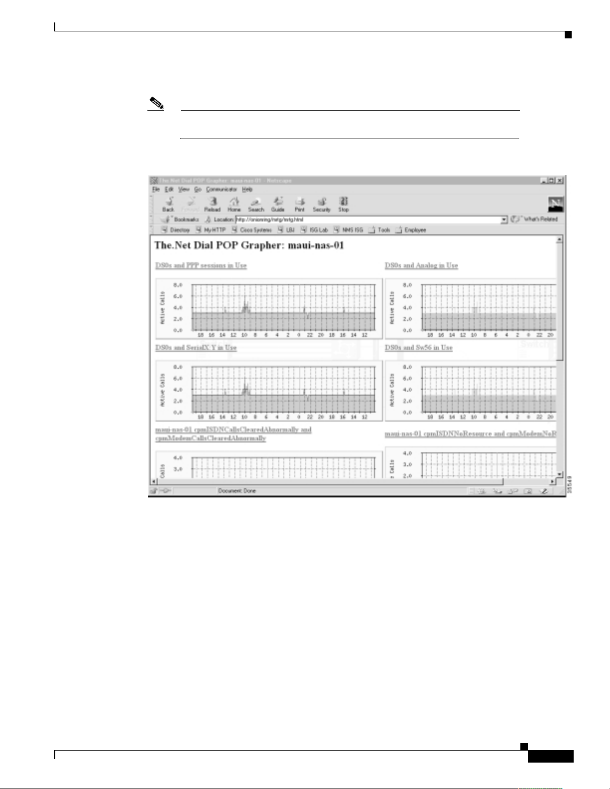
Task 3Using MRTG to Monitor and Graph Traffic Loads
How to Inspect and Interpret Data
Step 3
Use a web browser to view the MRTG output files in the web page directory.
Note
If the domain na me server (DN S) is not worki ng, a h ostna me ca nno t be use d by
MRTG. Use the IP address instead.
Figure 15 MRTG Graphs Viewed by Using a Web Browser
Basic Dial NMS Implementation Guide
$#
Page 66

How to Inspect and Interpret Data
Task 3Using MRTG to Monitor and Graph Traffic Loads
$$
Basic Dial NMS Implementation Guide
Page 67

Task 4Using Syslog, NTP, and Modem Call
Records to Isolate and Troubleshoot Faults
About Syslog
Syslog, Network Time Protoco l ( NT P), a nd mo dem ca ll re c ords wo rk toge the r to i sola te an d
troubleshoot faults in a dia l ac cess n etwork.
Syslog enables you to:
Figure 16 Cisco IOS Sending Syslog Messages to a Syslog Server
Centrally log and analyze configuration events and system error messages, such as router
configuration changes, interface up and down status, modem events, security alerts, environmental
conditions, trace ba cks, and CPU p roc ess overloads.
Capture client debug output sessi ons in a real- time sc enario .
Reserve telnet sessions f or maki ng c onfigura tions cha nges an d using
Telnet sessions that are cluttered with debug output interfere with troubleshooting procedures.
Reduce network downtime by knowing when the network has quality proble ms.
commands.
show
Syslog messages
Syslog server
Cisco IOS
Internal view
Syslog messages
written to
hard disk
You can enable syslog in any Cisco IOS device and send syslog messages to many different destinations
(host, buffer, console, history, and monitor).
Basic Dial NMS Implementation Guide
24528
$%
Page 68

About Syslog
Task 4Using Syslog, NTP, and Modem Call Records to Isolate and Troubleshoot Faults
By using the
travis-nas-01(config)#logging ?
Hostname or A.B.C.D IP address of the logging host
buffered Set buffered logging parameters
console Set console logging level
facility Facility parameter for syslog messages
history Configure syslog history table
monitor Set terminal line (monitor) logging level
on Enable logging to all supported destinations
rate-limit Set messages per second limit
source-interface Specify interface for source address in logging
transactions
trap Set syslog server logging level
logging ?
command, you can see the log settings for distinct destinations:
There are eight levels of syslog information in the Cisco IOS software. Monitor and manage logs
according to the severity level of the syslog message. By using the
logging trap ?
command, you can
see the logging severity levels:
travis-nas-01(config)#logging trap ?
<0-7> Logging severity level
alerts Immediate action needed (severity=1)
critical Critical conditions (severity=2)
debugging Debugging messages (severity=7)
emergencies System is unusable (severity=0)
errors Error conditions (severity=3)
informational Informational messages (severity=6)
notifications Normal but significant conditions (severity=5)
warnings Warning conditions (severity=4)
<cr>
Table 18 Logging Trap Severity Definitions
Message Type Description Syslog Message Severity Level
emergencies System unusable LOG_EMERG 0
alerts Immediate action needed LOG_ALERT 1
critical Critical conditions LOG_CRIT 2
errors Error condi tio ns LOG_ERR 3
warnings Warning conditions LOG_WARNING 4
notifications Normal but significant condition LOG_NOTICE 5
informational Informational messages only LOG_INFO 6
debugging Debugging messages LOG_DEBUG 7
In this case study, syslog is enabled on all Cisco access servers and backbone routers. Each device sends
syslog messages to the same log file on the sam e syslog server.
The terminology in the syslog messages can vary between different versions of Cisco IOS software.
To effectively manage syslog messages, ensure that wherever possible, the same version of Cisco IOS
software is running on al l ro uter s.
Note
For background info rmat ion on sy slog, go to
http://www.cert.org/security-improvement/practices/p041.html
$&
Basic Dial NMS Implementation Guide
Page 69

Task 4Using Syslog, NTP, and Modem Call Records to Isolate and Troubleshoot Faults
About NTP
The Network Time Protocol ( NTP ):
Provides a synchronized tim e base fo r networked rou ters, ser vers, and othe r devices.
Coordinates the tim e of ne twork events, which h elp s yo u under stand and trou bl eshoo t t he t ime
sequence of network events. For exampl e, c a ll re co rds f or spe cific use rs ca n be c or rel ate d wi thin
one millisecond.
Enables you to compare time logs fr om different network s, whi ch is essential for:
Tracking security inci dent s
`
Analyzing faults
`
Troubleshooting
`
Without precise time synchronization between all the various logging, debug output, management,
and AAA functions in the net work, you cannot make time compa rison s.
For a list of NTP clients, go to http://www.eecis.udel.edu/~ntp/software.html
About NTP
About Modem Call Records
A modem call record (MCR) is a type of syslog message that is:
Created when a user dials in and hangs up, but it is not generated until the end of the call.
Used to gather stati sti cs a nd modem -p erfor ma nce logs on a p er-call ba sis, s uc h as:
Modulation trends (V.9 0 verses V.34 ).
`
Call time durations (consist ent short co nnec tion times on a mo dem, regular Lost Carr ier
`
counts).
Unavailable user IDs.
`
PPP negotiation or authentication failures.
`
In this case study, the engineers filter modem call records ou t o f syslog and sto re th em in to fla t files on
a Unix host. The records are sorted by using cron jobs and pe rl scrip ts. A web-based MCR viewer
facility is used to:
Search the call records.
Extract historical an d statistic al info rmation about individual use rs and acce ss servers.
Basic Dial NMS Implementation Guide
$'
Page 70

About Modem Call Records
Figure 17 Web-Based MCR Viewer
Task 4Using Syslog, NTP, and Modem Call Records to Isolate and Troubleshoot Faults
You can view entire log files or portions of logs in the MCR vi ewer. In addition, you can parse for
specific users and other call attributes for a modem call (for example, modulation, error correction,
compression, disconne ct cause s, and ret rains).
Note
Modem call records are available in syslog starting with Cisco IOS
Releases 11.3AA and 12.0T.
%
Basic Dial NMS Implementation Guide
Page 71

Task 4Using Syslog, NTP, and Modem Call Records to Isolate and Troubleshoot Faults
Enabling NTP on a Cisco IOS Device
To enable NTP and related clocking services, follow these steps.
About Modem Call Records
Step 1
Step 2
Step 3
Step 4
From the Cisco IOS device , enter the foll owing comm ands. En able debug time stam ps and in clud e the
date, time, and milliseconds relative to the local time zone:
!
service timestamps debug datetime msec localtime show-timezone
service timestamps log datetime msec localtime show-timezone
!
Identify the local timezone and enable recurring time adjustments for daylight savings time by entering
the following commands:
!
clock timezone CST -6
clock summer-time CST recurring
!
Locate an NTP server that can be reached by the Cisco IOS device.
Specify the IP address for the NTP server and enable automatic-calendar updates by entering the
following commands:
!
ntp update-calendar
ntp server 172.22.255.1
!
Note
By default, the
ntp clock-period
command is enabled in so me Cisco IOS releases .
The Cisco IOS software appends an arbitrary number to the end of the command.
Step 5
Verify that the clock is synchronized with the NTP server by entering the following command:
travis-nas-01>show ntp status
Clock is synchronized, stratum 9, reference is 172.22.255.1
nominal freq is 250.0000 Hz, actual freq is 249.9987 Hz, precision is 2**24
reference time is BD123336.28CCF0C4 (18:09:42.159 CST Sat Jul 8 2000)
clock offset is 0.1183 msec, root delay is 61.84 msec
root dispersion is 0.93 msec, peer dispersion is 0.79 msec
travis-nas-01>
Inspect the status and time association. Clock sources are identified by their stratum levels. The
previous display shows a stratum level nine clock.
Note
If the NTP synchro niza tion doe s not ta ke pl ace , relo ad t he r oute r.
Basic Dial NMS Implementation Guide
%
Page 72

About Modem Call Records
Task 4Using Syslog, NTP, and Modem Call Records to Isolate and Troubleshoot Faults
Step 6
Verify that the router is rec eivi ng NTP packets from the NTP s erver b y entering the follo wing comman d:
travis-nas-01>show ntp association
address ref clock st when poll reach delay offset disp
*~172.22.255.1 127.127.7.1 8 984 1024 377 60.3 -0.89 0.8
* master (synced), # master (unsynced), + selected, - candidate, ~ configured
travis-nas-01>
The tilde (~) nex t to the IP a ddress of the NT P server means the NTP service is conf igured. Th e asterisk
(*) indicates succ essful s ynchro ni zat ion wi th the m aster c lock .
Setting Up an NTP Client
To set up an NTP client on a Sol aris v2. 6 workstatio n, follow these steps.
Step 1
Note
Locate an NTP serv e r tha t can b e rea ched b y the w ork sta tion. There a re man y available NTP servers on
the Internet. If your workstation cannot reach the Internet, locate an NTP server within your network.
Additional software is not required to set up NTP on the workstation if it is
running Solaris v2.6 (or later).
Step 2
Step 3
Note
A common practice is to configure an area border router as an NTP server for a
particular subnet. The area border router then points to an external NTP server.
Other equipment on that subnet uses the loopback 0 IP address on the area border
router as an NTP server.
Go to the /etc/inet directory and inspect the template file called ntp.client:
onionring:~$ cd /etc/inet
onionring:/etc/inet$ more ntp.client
# @(#)ntp.client 1.2 96/11/06 SMI
#
# /etc/inet/ntp.client
#
# An example file that could be copied over to /etc/inet/ntp.conf; it
# provides a configuration for a host that passively waits for a server
# to provide NTP packets on the ntp multicast net.
#
multicastclient 224.0.1.1
Copy ntp.client and creat e the ntp.c onf con figuration file in the / etc/in et default directory :
onionring:/etc/inet$ cp ntp.client ntp.conf
onionring:/etc/inet$
The NTP daemon reads ntp.conf at startup to locate the NTP server.
Note
You must have root-level permissions to edit or copy any files in the /etc/inet/
directory.
%
Basic Dial NMS Implementation Guide
Page 73

Task 4Using Syslog, NTP, and Modem Call Records to Isolate and Troubleshoot Faults
About Modem Call Records
Step 4
Step 5
Step 6
Edit the ntp.conf file by changi n g
multicastclient
to
followed by the IP address of the target
server
NTP server:
# @(#)ntp.client 1.2 96/11/06 SMI
#
# /etc/inet/ntp.client
#
# An example file that could be copied over to /etc/inet/ntp.conf; it
# provides a configuration for a host that passively waits for a server
# to provide NTP packets on the ntp multicast net.
#
server 172.22.255.1
Go to the directory /usr/lib/inet/ and start the NTP daemon by entering the
xntpd
command.
The daemon sets and maintains the time-of-day of the operating system in agreement with the master
time server.
onionring:/etc/inet$ cd /usr/lib/inet/
onionring:/usr/lib/inet$ ls
in.dhcpd xntpd
onionring:/usr/lib/inet$ xntpd
onionring:/usr/lib/inet$
Verify tha t the N TP dae m on is ru nni n g by ent eri ng the
onionring:/usr/lib/inet$ ntpq -p
remote refid st t when poll reach delay offset disp
==============================================================================
*maui-rtr-01.mau CHU(1) 8 u 49 64 377 1.08 -0.131 0.08
onionring:/usr/lib/inet$
ntpq -p
command:
The following information appe ars:
The remote NTP server to which the workstation is connected.
The reference ID.
The stratum level of the server.
The type of NTP packet that was received by the client (local, unicast, multicast, or broadcast).
The polling interval in seconds.
The reachability register in octal.
The current de lay of the ser ver in secon ds.
The current offset of the server in second s and the disper sion of the server in second s.
The delay, offset, and displacement b etw een the c lien t a nd the server in sec onds .
When the daemon starts, most of the time values will be zeros until there is a sufficient number of
queries taken by the daemon to de termine the corre ct offset.
Basic Dial NMS Implementation Guide
%!
Page 74

About Modem Call Records
Troubleshooting the NTP Client
Table 19 NTP Problems and Solutions
Problem Solution
The ntp.client file or the xntpd
daemon cannot be fou nd in the
directories shown in the examples.
The error message “No Associations
IDs Returned” when you enter the
ntpq -p
command.
Task 4Using Syslog, NTP, and Modem Call Records to Isolate and Troubleshoot Faults
Verify that the workstatio n is running Solaris v2.6 or a lat er
version of Solaris. Enter the
uname -a
command to see th e
version.
Versions earlier than Solaris v2.6 do not support NTP and must
be supplemented with additional NTP software av a ilab le f rom
http://www.sunfreeware.com/
There are three possible solutions:
The network traffic is slow, and the workstation has not
had time to poll the NTP server. Allow the workstation
enough time to issue the poll (a few seconds); then, enter
the
ntpq -p
The mulitcastclient line in the ntp.conf file was not
command.
replaced with the server line.
The NTP server you h ave chosen is down, or it is not
configured correctly.
Enabling Syslog and Modem Call Records in the Cisco IOS Software
To enab le syslog messages in the Cisco IOS software and send them to a syslog server,
follow these steps:
Step 1
Step 2
Inspect the current logging status by entering the following command:
travis-nas-01#show logging
Syslog logging: enabled (0 messages dropped, 0 flushes, 0 overruns)
Console logging: level debugging, 42 messages logged
Monitor logging: level debugging, 93 messages logged
Buffer logging: level debugging, 3 messages logged
Trap logging: level informational, 121 message lines logged
Log Buffer (8192 bytes):
travis-nas-01#
Set up a basic syslo g con figuratio n by e nte ring the f ollowing com ma nds . Se e Table 20 for comm an d
descriptions.
!
logging buffered 10000 debugging
no logging console guaranteed
logging console informational
!
!
logging trap debugging
logging facility local0
logging 172.21.100.100
!
%"
Basic Dial NMS Implementation Guide
Page 75

Task 4Using Syslog, NTP, and Modem Call Records to Isolate and Troubleshoot Faults
Table 20 Logging Command Descriptions
Command Purpose
logging buffered 10000 debugging
Sets the internal log buffer to 10000 bytes for debug output.
New messages overwrite old messages.
You can tun e buffered-logging pa ram ete rs for c oll ecti ng logs
on a NAS when yo u are a t a remo te locatio n. For e xam ple, turn
on debugs and start logging them in the history buffer. Make
your test call; then, re-connect in shell mode and inspect the
debugs.
logging console informational
no logging console guaranteed
Sends the most urgent informational logs to the console port in
the event the IP network or syslog server fails. Alternatively,
send messages to the console by using the commands
console er rors
or
logging console warnings
About Modem Call Records
logging
.
Step 3
Caution
Logging console c an caus e the r oute r to
intermittently freeze up as soon as the
console port overloads with lo g
messages. Debugs and modem call
records sent to the console port are
potentially destructive to the Cisco IOS
software.
logging trap debugging
logging 172.21.100.100
logging facility local0
Enables logging up to the debug level (all eight levels).
Specifies the IP address of the syslog server.
Assigns a logging-facility tag (local0) to the syslog m essages
for this device. The tag must match the facility number
configured in the syslog.conf file on the Unix host. See Step 1
in “Configuring the Syslog Daemon” sect ion on page 76.
In this case study, each device sends syslog messages to the
same log file on the same syslog server.
Enable modem call re cords i n the Ci sco IO S by enter ing th e foll owing comm and:
!
modem call-record terse
!
A modem call record, which is a syslog message, looks like this:
May 26 22:04:23.346 CST: %CALLRECORD-3-MICA_TERSE_CALL_REC: DS0 slot/contr/chan=
0/0/0, slot/port=2/14, call_id=26, userid=(n/a), ip=0.0.0.0, calling=4082322078,
called=3241933, std=V.34+, prot=LAP-M, comp=V.42bis both, init-rx/tx b-rate=264
00/24000, finl-rx/tx b-rate=28800/24000, rbs=0, d-pad=None, retr=1, sq=4, snr=27
, rx/tx chars=136/6470, bad=2, rx/tx ec=134/184, bad=0, time=594, finl-state=Ste
ady, disc(radius)=(n/a)/(n/a), disc(modem)=DF03 Tx (host to line) data flushing
- OK/Requested by host/DTR dropped
Basic Dial NMS Implementation Guide
%#
Page 76

About Modem Call Records
Task 4Using Syslog, NTP, and Modem Call Records to Isolate and Troubleshoot Faults
Step 4
(Optional) To disable syslog messages and SNMP traps when dia l interfaces go up and down, use the
commands
no logging event link-status
are legitimate events on dial interfaces, these events should not cause alarms as LAN and WAN
interfaces would.
!
interface Serial1/0/0:4:23
no logging event link-status
no snmp trap link-status
!
interface Group-Async0
no logging event link-status
no snmp trap link-status
!
In this example, on ly the four th T 1 of a T 3 card is sh own.
Note
In some Cisco IOS images , the
default.
Configuring the Syslog Daemon
In this case study, all the syslog messages from the access servers are sent to a single log file. The syslog
messages from the backbone routers are sent to a different log file.
and
no snmp trap link-status
logging event link-status
. Although up and down events
command is disa bled b y
Step 1
To configure the syslog daemon on a Solaris syslog server, follow these steps:
On the syslog server, edit the file syslog.conf in the /etc/ directory by using a text editor. To get syslog
working, you must add the following line to the file:
|
local0.debug /var/log/router.log
|
The local facility number is
Cisco IOS device. See t he
The log file path name is
One tab exists between the facility number and the path name. Spaces are not permitted.
local0.debug
logging facility
/var/log/router.log
. It must match the facility num ber co nfigured in the
command in Table 20.
You can de fine any directory loc ation/p ath for th e .txt log file.
In the following example, the new line is in
"syslog.conf" 53 lines, 1861 characters
#ident "@(#)syslog.conf 1.3 93/12/09 SMI" /* SunOS 5.0 */
#
# Copyright (c) 1991-1993, by Sun Microsystems, Inc.
#
# syslog configuration file.
#
# This file is processed by m4 so be careful to quote (`') names
# that match m4 reserved words. Also, within ifdef's, arguments
# containing commas must be quoted.
#
#
#
#
bold
:
%$
Basic Dial NMS Implementation Guide
Page 77

Task 4Using Syslog, NTP, and Modem Call Records to Isolate and Troubleshoot Faults
#Following is the new line. It adds a logging facility number and direcory path for the
#log file (router.log).
local0.debug /var/log/router.log
About Modem Call Records
Step 2
Step 3
Step 4
Note
The previous syslog.conf example has been ab breviated to fit this docume nt. The
actual file size is m uch lar g er tha n the e xample. Add th e new line to the end of the
file.
Create the log file and check the read/write privileg es by entering the following commands:
aurora:/etc ->touch /var/log/router.log
aurora:/etc ->ls -l /var/log/router.log
-rw-r--r-- 1 root other 27110 Jul 8 19:56 /var/log/router.log
aurora:/etc ->
Verify the syslog da emon is run ning by entering the
ps -elf | grep syslog
command from the
/etc directory . If the daemon is ru nning, a pr ocess ID is re turned b y the system (for exa mple, 169). I f the
daemon is not r unn ing, no I D i s r etur ned .
aurora:/etc ->ps -elf | grep syslog
8 S root 169 1 0 41 20 60756cc8 187 604e3156 Jun 19 ? d
aurora:/etc ->
Activate the configuration changes you made in syslog.conf by restarting the syslog daemon. Enter the
start/stop S74syslog scripts from the /etc/rc2.d directory.
aurora:/etc ->rc2.d/S74syslog stop
Stopping the syslog service.
aurora:/etc ->rc2.d/S74syslog start
syslog service starting.
aurora:/etc ->ps -elf | grep syslog
8 S root 4405 1 0 44 20 6042d320 187 604e3156 09:16:35 ? d
aurora:/etc ->
Confirm that a new syslog process ID was assigned (for example , 4405) aft er the start/st op process .
Note
You must have root-level permissions to run system scripts, such as the files in
/etc/rc2.d
Basic Dial NMS Implementation Guide
%%
Page 78
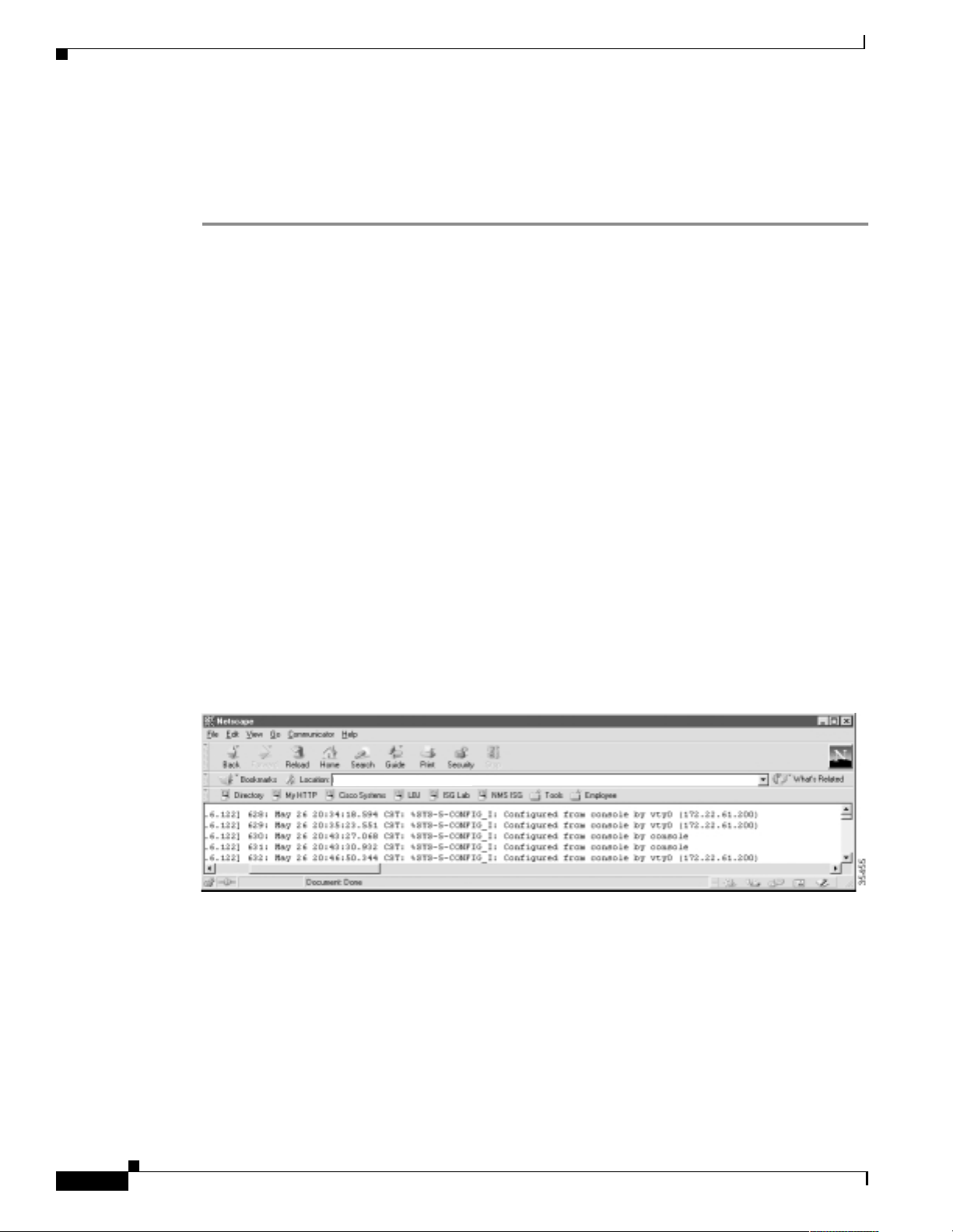
Task 4Using Syslog, NTP, and Modem Call Records to Isolate and Troubleshoot Faults
About Modem Call Records
Inspecting Syslog Messages in t he Log File
To inspect syslog messages by using Cisco IOS commands, Unix commands, FTP, and a web browser,
follow these steps:
Step 1
Step 2
Step 3
From the Cisco IOS device, create basic syslog messages by entering these commands:
travis-nas-01#configure terminal
Enter configuration commands, one per line. End with CNTL/Z.
travis-nas-01(config)#^Z
travis-nas-01#configure terminal
Enter configuration commands, one per line. End with CNTL/Z.
travis-nas-01(config)#^Z
travis-nas-01#
From the syslog server , ve rify that the syslog messages went in to the log f ile. Enter the
to monitor the last 10 lines of an active log file. To exit tail -f mode, press
aurora:/etc ->tail -f /var/log/router.log
May 26 17:43:12 [172.21.101.20.6.122] 629: May 26 20:35:23.551 CST: %SYS-5-CONFIG_I:
Configured from console by vty0 (172.22.61.200)
May 26 17:51:15 [172.21.101.20.6.122] 630: May 26 20:43:27.068 CST: %SYS-5-CONFIG_I:
Configured from console by console
May 26 17:51:19 [172.21.101.20.6.122] 631: May 26 20:43:30.932 CST: %SYS-5-CONFIG_I:
Configured from console by console
May 26 17:54:38 [172.21.101.20.6.122] 632: May 26 20:46:50.344 CST: %SYS-5-CONFIG_I:
Configured from console by vty0 (172.22.61.200)
^C
aurora:/etc ->
Ctrl-C
.
tail -f
command
View the syslog messages in a web browser. Notice the wide horizontal scroll bar, which is helpful for
viewing debug messages and modem call records.
Figure 18 Syslog Messages that Appear by Using FTP and a Web Browser
%&
ftp://sam@172.23.84.22/var/log/router.log
Basic Dial NMS Implementation Guide
Page 79

Task 4Using Syslog, NTP, and Modem Call Records to Isolate and Troubleshoot Faults
Ta ble 21 shows the generic URL syntax to use. Be sure to repla ce the variables with you r own
information. The FTP ser ver automatically pro mpts you for a l ogin password.
Table 21 URL Syntax Descriptions and Examples
Generic URL Syntax Description Example
ftp://
username@host/directory-path
Uses FTP to view
logs from a remote
location.
file://
directory-path
Views l ogs on a
local host.
About Modem Call Records
ftp://sam@172.2 3.84. 22/var/log/ro ut er.l
og
file://var/log/router.log
Basic Dial NMS Implementation Guide
%'
Page 80

About Modem Call Records
Task 4Using Syslog, NTP, and Modem Call Records to Isolate and Troubleshoot Faults
&
Basic Dial NMS Implementation Guide
Page 81

Task 5Setting Up a Web Portal for the
Dial NMS
About a Web Portal
A web portal for the dial NMS i s a comb in atio n of CG I scr ipts and HTML lin ks use d to suppo rt a di al
Internet access servic e.
As the number o f devices and a ppli cati ons i n a network inc rease , t he o pe ratio ns s uppo rt te am may
become inundat ed w it h a myr i ad of m an ag emen t pr odu cts. To support a dial s ervi ce, a we b p orta l
provides easy access to:
Product manuals, design gui des, white papers, and t roublesh ooting guides.
Light-weight tools and sc ripts.
Network policies, proced ures, a nd reports .
Periodic and just-in-time reporting.
The help desk can access operational information
`
(for example, current connected caller status).
The operations staff can report on current service levels.
`
Tip s
For more information on building a mana gement intran et, go to
http://www.cisco.com/warp/public/cc/serv/mkt/nmps/ent/tech/bmi_wi.htm
Table 22 Utilities Provided by the Web Portal for the Dial NMS
Utility Function
Documentation Center A web server used as an online-documentation hub to share
network operations in forma ti on.
Device Linker A web page used for boo kmark ing URLs for quick d evice telnet
and out of band (console) acc ess.
See the “Building a Device Linker Web Page” section on page 83.
Basic Dial NMS Implementation Guide
&
Page 82

About a Web Portal
Task 5Setting Up a Web Portal for the Dial NMS
Table 22 Utilities Provided by the Web Portal for the Dial NMS (continued)
Utility Function
Cisco IOS CLI Command Center A web page that provides HTTP access to frequently used
Cisco IOS CLI commands. The operations team and help desk can
use this utility to troubleshoot connectivity problems.
See the “Using HTTP to Access CLI Commands” section on
page 86.
IP Tracker A web page that uses two scripts to keep track of IP address block
assignments by using DNS reverse lookup z ones.
See the “Creating an IP Tracker Web Page” section on page 96.
SNMP Comma nder A script that aids the MIB research task by enabling engi neers to
build web-based object identif ication (OIDs) bookmarks. You can
poll for network statistics by using OID bookmarks and a w eb
browser. No keyboard is required.
See the “About SNMP Commander” sect ion o n page 49.
Syslog Viewer A utility that use s FTP to access a syslog serv er and a web browser
to view syslog messages. Migration to HTTP is strai ghtforward
after security issues are add resse d. The us e of non-w rappi ng text
is useful when v iewing d ebug messa ges a nd mode m cal l r ecor ds.
See the “Inspecting Syslog Messages in the Log File” section on
page 78.
Modem Call R ecor d Viewer Light -we ight scri pts used to p ars e and v iew modem call recor ds.
See the “About Syslog” section on page 67.
CiscoWorks 2000 Resource
Manager Essentials
A utility used to remotely monitor and maintain devices through
a web-based br owser inte rfac e.
See the “Task 8—Using CiscoWorks 2000 Resource Manager
Essentials” section on page 117.
&
Basic Dial NMS Implementation Guide
Page 83

Task 5Setting Up a Web Portal for the Dial NMS
Line 1
RS-232
cable
Device Linker
Cisco AS5800
Cisco 2511 terminal server
Telnet access
telnet://172.21.10.10
HTTP access to the CLI
http://172.21.10.10
35192
OOB console access
telnet://172.21.10.1:2001
Building a Device Linker Web Page
A device linker web page:
Simplifies access to the many device-management interfaces in the network.
Provides links to the te lne t, con sol e, an d HT TP por t s of C isco IO S devices.
Figure 19 Device Linker Used to Access Devices
About a Web Portal
Step 1
Step 2
Step 3
By using a Cisco terminal server for out-of-band console access, such as a Cisco 2511, the consoles are
available at TCP port 20xx on a terminal server. The target line number replaces xx. For example to get
to line 1, telne t t o po rt 2 001 . The equ ivalent URL is t e lne t://1 72.2 1. 101. 25 0:200 1
To build a device linker web page, foll ow these steps:
Collect the IP addresses for the Cisco IOS devices.
Collect the device con sole out -of- ba nd ( OOB) pa ths f or the t erm i nal ser ver an d the li nes conne ct ed to
Cisco IOS devices.
Create a basic HT ML table and enter the inf ormation f or each dev ice. The telnet a nd HTTP inf ormati on
is in bold in the following HTML code fragment. Step 4 shows what the table looks like in a web
browser.
<html>
<head>
<title>Dial The.Net Device Linker</title>
</head>
<body>
<h2>Dial The.Net Device Linker</h2>
<table border="1">
<tr>
<td>Name</td>
<td>IP</td>
<td>Console</td>
<td>Hardware Type</td>
<td>Comments</td>
</tr>
<tr>
Basic Dial NMS Implementation Guide
&!
Page 84

About a Web Portal
Task 5Setting Up a Web Portal for the Dial NMS
<td><a href="http://172.21.10.1">travis-nas-01</a></td>
<td><a href="telnet://172.21.10.1">172.21.10.1</a></td>
<td><a href="telnet://172.21.101.250:2001">travis-oob-01:2001</a></td>
<td>5800</td>
<td>Dial POP #1</td>
</tr>
</table>
</body>
</html>
Table 23 Functions and Parameters for Designing a Device Linker Web Page
Function Formula Example
OOB console access telnet://termserver-ip:20XX telnet://172.21.101.250:2001
Basic IP access telnet://ip-address telnet://172.21.10.1
IOS HTTP access http://ip-address http://172.21.10.1
Step 4
Post the device linker web page to a WWW server in the NOC.
Figure 20 A Device Linker Management Page
&"
Basic Dial NMS Implementation Guide
Page 85
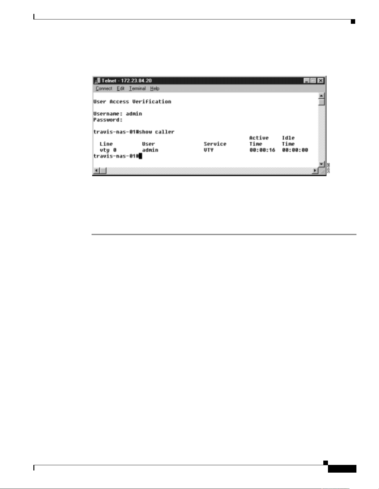
Task 5Setting Up a Web Portal for the Dial NMS
About a Web Portal
Step 5
Click on an active device link. After a telnet session opens, log in.
Figure 21 Console Port Login
Troubleshooting a Cisco 2511 Console Connection
If you cannot access the console of a device, follow these steps:
Step 1
Step 2
Verify that the configuration on the terminal server is correct. Telnet is the only service that must be
supported to access the lines . The foll owing configuration fragm ent shows you how to configure
16 TTY lines on a Cisco 2511 terminal server.
!
line 1 16
no exec
transport input telnet
!
If the console port is blocke d, you may need to telnet to the termi nal serv er and clear the line. Ent er the
show users
c2511-oob#show users
Line User Host(s) Idle Location
0 con 0 admin idle
4 tty 4 admin incoming 0 dhcp-172-71-218-198.guessme.com
* 10 vty 0 admin incoming 0 dhcp-172-71-218-198.guessme.com
c2511-oob#clear line tty 4
[confirm]
[OK]
c2511-oob#show users
Line User Host(s) Idle Location
0 con 0 admin idle
* 10 vty 0 admin incoming 0 dhcp-172-71-218-198.guessme.com
EXEC command followed by the
clear line
type number
command.
Basic Dial NMS Implementation Guide
&#
Page 86

About HTTP Access to the CLI
Task 5Setting Up a Web Portal for the Dial NMS
Step 3
(Optional) Sometimes administrators inadvertently leave lines in use. To make idle telnet sessions end
after 30 minutes, enter the
!
line 1 16
no exec
exec-timeout 30 0
transport input telnet
!
exec-timeout 30 0
About HTTP Access to the CLI
Using web-based a cce ss to the C LI re du ces the ne ed for t elnet sessi ons t o moni tor or verify net work
operations. Telnet sessions can be reser ved for ac tions suc h as ma king c onfiguration c hang es.
Additionally, sending syslog to a syslo g server prevents telnet sessions fr om be co ming cl utt ered w it h
debug output.
HTTP access to the CLI is:
Very difficu lt to s ecure. On e way of secur ing a ro uter is to use a ccess-con trol lists o n all VT Y lines.
Enable only devices in the NOC to access the VTY lines.
Not recommende d for servi ce pro vider s. If used, y ou s hould wei gh the perc ei ved ease o f use v ers us
the additional security issues involved with HTTP access to a network device.
The Cisco IOS CLI Command Center is a web page utility that pro vides HTTP acc ess to CLI commands
on a router. HTTP access to the CLI simplifies the troubleshooting tasks for a help desk.
command on all the lines.
Using HTTP to Access CLI Commands
To manage a dial Internet access service by using HTTP access to CLI commands, follow these steps:
Step 1
Enable HTTP services on the Cisco IOS device by entering th e following comm ands:
!
ip http server
ip http authentication aaa
!
Table 24 Command Descriptions
Command Purpose
ip http server
ip http authentication aaa
Enables the router to function as an HTTP server.
Uses the AAA facility as an authentication method
for HTTP server users.
&$
Basic Dial NMS Implementation Guide
Page 87

Task 5Setting Up a Web Portal for the Dial NMS
About HTTP Access to the CLI
Step 2
Create a table i n an HT ML w eb page and en ter you r li st of fr eq uent ly use d Cisco IO S CLI co mma nds.
Note
To create the link for a CLI command, specify the IP address of the Cisco IOS
device followed by the command. Remember to include the forwar d slashes (/)
between each command mode and key word.
Table 25 Formula and Example for Linking a CLI Command
Formula Example
http://ip-address/exec/ios-key-word/.../cr http:/172.23.84.20/exec/sh/caller/cr
The web page can in c l ud e many types of co mmands useful fo r managing a dial In ter n et a ccess service,
including:
System commands (Table 26)
Interface comma nds (Table 27)
Call state commands (Table 28)
Debug commands (Table 29)
Table 26 System Commands
show running configuration show file systems show ip route
show version dir show ip route static
show modem version show flash show ip route connected
Table 27 Interface Commands
show controller t1 show ip interface brief show interface Fast
Ethernet0/0/0
show isdn service show interface show line
show isdn status
Basic Dial NMS Implementation Guide
&%
Page 88

About HTTP Access to the CLI
Table 28 Call State Commands
show modem show caller show users
show modem call-stats show caller ip show dialer
show modem ? show caller timeout show dialer map
Table 29 Debugging Commands
show logging debug isdn q931 debug aaa
clear counters debug modem debug aaa
clear logging debug ppp negotiation debug aaa accounting
show debug debug ppp authentication debug aaa per-user
undebug all debug dialer debug vtemplate
Task 5Setting Up a Web Portal for the Dial NMS
show caller ?
authentication
authorization
debug dialerpacket debug vprofile
Step 3
Post the HTML page that you created in Step 2 to a web server.
&&
Basic Dial NMS Implementation Guide
Page 89

Task 5Setting Up a Web Portal for the Dial NMS
Figure 22 Cisco IOS CLI Commander
About HTTP Access to the CLI
For the source code that created the Cisco IOS CLI Commander in Figure 22, go to
http://www.cisco.com/univercd/cc/td/doc/cisintwk/intsolns/dialnms/httpcli.txt
Basic Dial NMS Implementation Guide
&'
Page 90
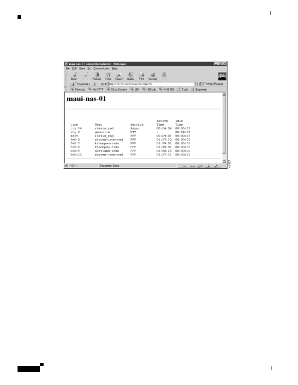
About HTTP Access to the CLI
Task 5Setting Up a Web Portal for the Dial NMS
Step 4
Click on a CLI comm a nd an d v i ew the com mand ou t put in a we b p age.
Figure 23 Output for the Show Caller Command
'
Basic Dial NMS Implementation Guide
Page 91

Task 6Managing IP Addresses by Using DNS
About Managing IP Addresses
Managing IP addre sses is a p rimary n etwork a dm inist rat ion f un ction. Assign i ng an d r e moving
IP addresses can be tediou s and error pro ne. Regardless— you must manag e IP addresse s to avoid
duplicate IP subnets and addre sses.
Domain Name System ( D NS) se rvers pr ovide two kinds of funda m ental l oo kup se rv ices:
Forward lookups
common kind of loo kup perf or med.
Reverse lookups
reverse-lookup zones are important tools used for tracking IP address assignments.
In this case study, the dial engineers at THEnet:
Have received a block of IP addresses from the NOC with DNS adm inistra tive rights and
instructions for setting up IP address space .
Track IP address assignments by using DNS reverse lookup zones within the existing DNS service.
Use the application Cisco Network Registrar (CNR) and its CLI to manage the IP address database.
CNR is a full-featured IP address management solution for both enterprise and service provider
networks. It includes ad vanced DNS an d Dy na mic Host C onfigurati on Pr otoc ol ( DHCP) se rvers.
—Used for looking up the IP address of a provided device name. This is the most
—Used for looking up a device name of a provided IP address. Administratively,
Note
This section assumes you ar e familia r with the basic s of DNS. F or mo re information ab out
DNS, see
is 1565925122.
Table 30 Related References and Documents
Reference URL
Internet Software Consortiu m for BIND
Name Daemon)—Descr ibes the DNS protocols.
Cisco Network Registrar
user guides and reference manuals.
DNS and Bind
, Third Edition, by Paul Albitz a nd Cricket Liu. The ISBN number
(Berkeley Internet
—A collection of DNS/DHCP
http://www.isc.org/products/BIND/
http://www.cisco.com/univercd/cc/td/doc
/product/rtrmgmt/ciscoasu/nr/index.htm
Basic Dial NMS Implementation Guide
'
Page 92

About Managing IP Addresses
Using Cisco Network Registrar CLI Command s
Database locking prevents multiple users from writing to the same database records concurrently.
However, an a dm inist rato r ma y occa siona ll y not exit a se ssion prope rly, and the databa se ma y be l eft
locked. To release the lock on the database, use the
Network registrar comma nds sent f rom t he U n ix sh ell loc k t he da ta base onl y w hil e c omm an ds ar e
running.
The name for a reverse zone is the inverse of your Internet network number, added to the special domain
in-addr.arpa. For example if the network number is 1.2.3.0, the reverse zone name is 3.2.1.in-addr.arpa.
A second example i s the n etwork num be r 1.2 .0. 0 w ith the reverse zone of 2.1.i n- addr.arpa.
For a description of the network registrar CL I command s, go to
http://www.cisco.com/univercd/cc/td/doc/product/rtrmgmt/ciscoasu/nr/nr30t/cliref/cli01.htm#68483
To qui ckly perf orm admin istrative tasks by using CNR CLI commands , follow these steps:
force-lock
Task 6Managing IP Addresses by Using DNS
network registrar command.
Step 1
Step 2
Step 3
Step 4
Log in to the Cisco Network Registrar application by entering the following directory path:
/opt/nwreg2/usrbin/nrcmd
nrcmd>
After logging in, the command mode is accessed and the prompt “nrcmd>” appears.
To create an account for an administrator, enter the
nrcmd> admin bob create password=xyz
In this example, the administrator name is
To see a list of existing administrators, enter the
nrcmd> admin list
bob: password=********;
omar: password=********;
padma: password=********;
Note
Inspect a reverse zone by entering the
nrcmd> zone 101.21.172.in-addr.arpa. listRR
100 Ok
Static Resource Records
@ IN SOA onionring.the.net. netadmin.the.net 1997121601
3600 1800 86400 86400
@ IN NS onionring.the.net.com.
205 IN PTR unused-205.the.net.
203 IN PTR unused-203.the.net.
210 IN PTR unused-210.the.net.
204 IN PTR unused-204.the.net.
1 IN PTR unused-1.the.net.
10 IN PTR unused-10.the.net.
101 IN PTR unused-101.the.net.
102 IN PTR unused-102.the.net.
103 IN PTR unused-103.the.net.
104 IN PTR unused-104.the.net.
(truncated for brevity)
The
admin list
command is a r ead -onl y co mman d.
zone
. The password is
bob
admin list
command and
command and an associated password:
admin
.
xyz
command:
option:
listRR
'
Basic Dial NMS Implementation Guide
Page 93

Task 6Managing IP Addresses by Using DNS
About Managing IP Addresses
Step 5
Step 6
Step 7
Step 8
When working with a re vers e zone, you can map an IP address to a ro uter by ente ring the
and the
nrcmd> zone 101.21.172.in-addr.arpa. addRR 7 PTR bobslake-nas-01.the.net
addRR
Remove a resource record by entering the
nrcmd> zone 101.21.172.in-addr.arpa. removeRR 7 PTR unused-07.the.net
resource record (RR) option:
zone
command and
removeRR
option:
zone
command
T o minimize the lock-time on the database, enter the following CNR command from the Unix command
line. Use q uotat ions (“ ”) to con tain the c omman d and pass it to the she ll.
/opt/nwreg2/usrbin/nrcmd "zone 101.21.172.in-addr.arpa. listRR"
Note
The NRCMD command mode is not used.
Sort the records and parse the output by entering the following CNR command from the Unix command
line:
/opt/nwreg2/usrbin/nrcmd "zone 101.21.172.in-addr.arpa. listRR" | sort -n | more
username: password:
0 IN PTR broadcast-0.the.net.
@ IN NS onionring.the.net.
@ IN SOA onionring.the.net. netadmin.the.net.101.
21.172.in-addr.arpa. 1997121606 3600 1800 86400 86400
Dynamic Resource Records
Static Resource Records
1 IN PTR unused-1.the.net.
2 IN PTR unused-2.the.net.
3 IN PTR unused-3.the.net.
4 IN PTR unused-4.the.net.
5 IN PTR unused-5.the.net.
6 IN PTR unused-6.the.net.
7 IN PTR unused-7.the.net.
8 IN PTR unused-8.the.net.
9 IN PTR unused-9.the.net.
10 IN PTR unused-10.the.net.
(truncated for brevity)
Basic Dial NMS Implementation Guide
'!
Page 94

About Managing IP Addresses
Task 6Managing IP Addresses by Using DNS
Step 9
Step 10
To add an “A” Resource Record (RR) to a forward zone (domain) and map a name to an IP address,
enter the
nrcmd> zone the.net. addRR bobslake-nas-02 A 172.21.10.18
@ IN NS onionring.the.net.
@ IN SOA onionring.the.net. netadmin.the.net. 56 10800
3600 604800 86400
Dynamic Resource Records
Static Resource Records
aurora IN A 172.21.100.100
bobslake-nas-01 IN A 172.21.10.10
bobslake-nas-02 IN A 172.21.10.18
doc-2610-01 IN A 172.21.10.13
doc-3810a-01 IN A 172.21.10.14
doc-3810d-01 IN A 172.21.10.15
doc-AS5850-01 IN A 172.21.10.11
doc-core-01 IN A 172.21.10.5
doc-core-02 IN A 172.21.10.6
doc-core-03 IN A 172.21.10.7
(truncated for brevity)
In the previous example, the
Creates an A r ecor d for t he. ne t
Assigns the IP address 172.21.1 0.18 to the route r bobslake- nas-0 2
zone
command:
zone
command:
To reload the server to make all IP assignments or changes take effect, enter the following command:
nrcmd> server dns reload
Note
Reload all cha nges i n to th e D NS da taba se, so th at th e ch ange s ca n b e re solved
upon lookup.
'"
Basic Dial NMS Implementation Guide
Page 95

Task 6Managing IP Addresses by Using DNS
Using a Batch File to Make Changes to a DNS Configuration
CNR can use batch files to make large and small-scale changes to the DNS configuration within your
network.
To use the batch-file facility to add and remove entries, follow these steps:
About Managing IP Addresses
Step 1
Step 2
Define the batch file by entering
zone the.net. addRR doc-core-02 A 172.21.10.6
zone the.net. addRR doc-core-03 A 172.21.10.7
zone 10.21.172.in-addr.arpa. removeRR 6 PTR unused-6.the.net.
zone 10.21.172.in-addr.arpa. removeRR 7 PTR unused-7.the.net.
zone 10.21.172.in-addr.arpa. addRR 6 PTR doc-core-02.the.net.
zone 10.21.172.in-addr.arpa. addRR 7 PTR doc-core-03.the.net.
server dns reload
commands:
zone
The previous batch-file example sh ows how to add t wo new device/IP addresses. In addition to adding
two “A” records (lines 1 and 2), remove the “unused” PTR records from the reverse zone (lines 3 and
4) before adding the new “PTR” records, in place of the unused records, to the reverse zone (lines 5 and
6). See line 7 to reload the DNS server.
Run the script by using the -b option:
nrcmd> -b < 172.21.10.batch
The following output appears:
nrcmd>
zone the.net. addRR doc-core-02 A 172.21.10.6
100 Ok
doc-core-02 IN A 172.21.10.6
nrcmd>
zone the.net. addRR doc-core-03 A 172.21.10.7
100 Ok
doc-core-03 IN A 172.21.10.7
nrcmd>
zone 10.21.172.in-addr.arpa. removeRR 6 PTR unused-6.the.net.
100 Ok
removing 6 IN PTR unused-6.the.net.
nrcmd>
zone 10.21.172.in-addr.arpa. removeRR 7 PTR unused-7.the.net.
100 Ok
removing 7 IN PTR unused-7.the.net.
nrcmd>
zone 10.21.172.in-addr.arpa. addRR 6 PTR doc-core-02.the.net.
100 Ok
6 IN PTR doc-core-02.the.net.
nrcmd>
zone 10.21.172.in-addr.arpa. addRR 7 PTR doc-core-03.the.net.
100 Ok
7 IN PTR doc-core-03.the.net.
nrcmd>
server dns reload
100 Ok
Basic Dial NMS Implementation Guide
'#
Page 96

About Managing IP Addresses
Creating a Primary Forwar d Zone
T o create a domain (or forward zone) and include all forward mapping (the “ A” records) for the domain,
follow these steps:
Task 6Managing IP Addresses by Using DNS
Step 1
Step 2
Create a domain a nd inc lude all for ward mappin g (the “A” records) by en tering the
the
nrcmd> zone the.net create primary file=the.net.zone.txt
create
option:
command with
zone
To cr eate new subnets by using the CLI, import a BIN D zone definition file, whi ch can be edi ted by
using an ASCI text editor. The following example shows an edited BIND file.
@ IN SOA onionring.the.net. netadmin.the.net. (
2000071600 ; serial number
3600 ; Refresh 1 hours
1800 ; Retry 30 minutes
86400 ; Expire 24 hours
86400 ; TTL 24 hours
)
IN NS onionring.the.net.
doc-rtr58-01 IN A 172.21.101.20
doc-rtr54-01 IN A 172.21.101.21
doc-rtr53-01 IN A 172.21.101.22
doc-rtr53-05 IN A 172.21.101.23
doc-3810a-01 IN A 172.21.10.14
doc-3810d-01 IN A 172.21.10.15
doc-ubr7246-01 IN A 172.21.10.16
doc-switch-02 IN A 172.21.10.17
Verify that the primary zone was created by entering the
nrcmd> zone the.net listRR
100 Ok
Static Resource Records
@ IN SOA onionring.the.net.
netadmin.the.net.0
@ IN NS onionring.the.net.
doc-rtr58-01 IN A 172.21.101.20
doc-rtr54-01 IN A 172.21.101.21
doc-rtr53-01 IN A 172.21.101.22
doc-rtr53-05 IN A 172.21.101.23
(Truncated for brevity)
Dynamic Resource Records
command with the
zone
listRR
option:
Creating an IP Tracker Web Page
An IP tracker web page :
Provides web access to the IP database that is managed by Cisco Network Registrar.
Retrieves current IP address bloc k as signm ents fr om a D NS server.
Uses two CGI scripts to provide a web-enabled look into DNS for each zone.
Basic Dial NMS Implementation Guide
'$
Page 97
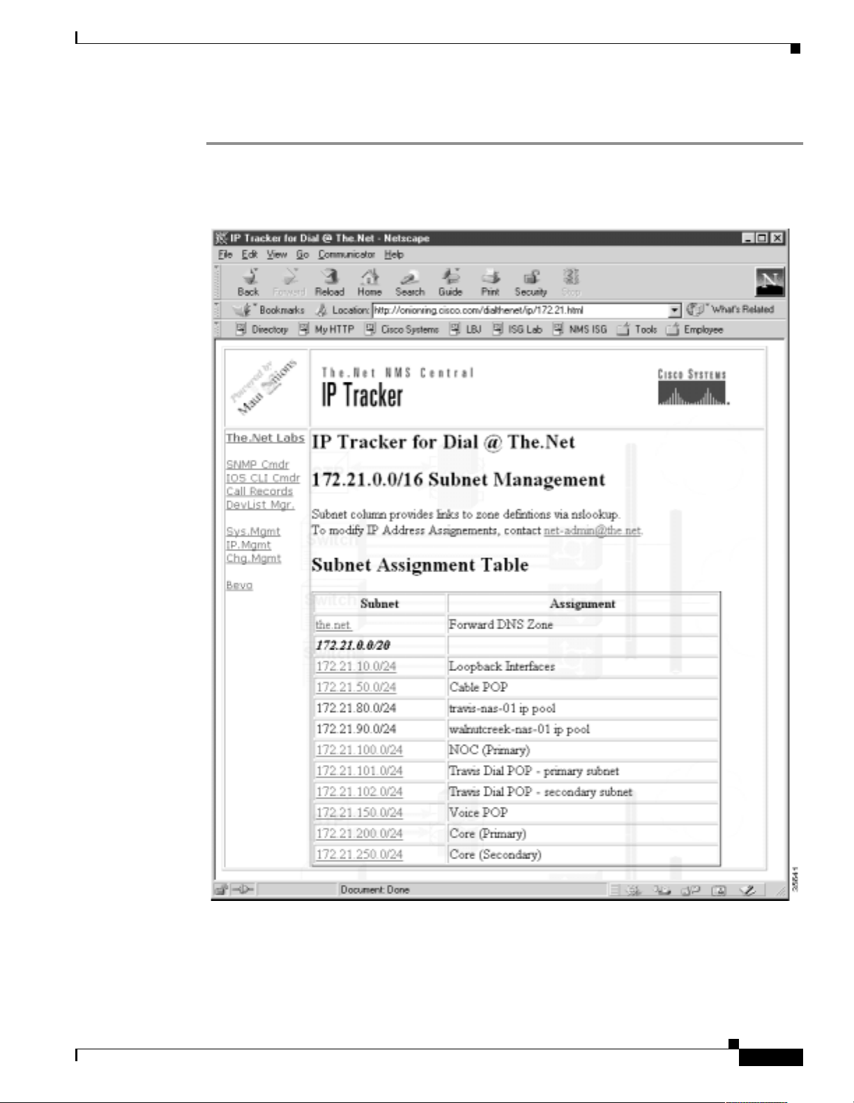
Task 6Managing IP Addresses by Using DNS
To create an IP trac ker web page, foll ow these s teps :
About Managing IP Addresses
Step 1
Become familiar with the la yout of an IP trac ker web page. I n Figure 24, the subnet column sho ws a l ist
of all managed zones. The assign ment column describes the purpose of ea ch zone.
Figure 24 IP Tracker Web Page
Basic Dial NMS Implementation Guide
'%
Page 98

About Managing IP Addresses
Task 6Managing IP Addresses by Using DNS
Step 2
Understand how the CGI scripts function.
There are two scripts th at w o rk to geth er to return an NSLOOKUP list query (ls) for a sp eci fied zone in
a CGI link.
dnszone.pl
—Runs the CGI process. In the subnet column in Figure 24, the entry 172.21.10.0/24 is
an active link that calls the dn szone .pl scri pt.
The active link is coded as:
<td><a href=" /c gi-lwt /dnsz one .pl ?zon e= 10.21 .17 2.i n -addr.arpa.">172 .21.1 0. 0/ 24</ a>< /td >
Once invoked, dnszone.pl calls the second script,
dnszone_dump—
An expect script that steps through the NSLOOKUP in teract i v e mode and re turns
dnszone_dump
.
the output of a “ls [ZONE]” command to the dnszone.pl script. The zone list, returned to the
requesting web-based mana gement browser, appears:
ls 10.21.172.in-addr.arpa.
[www.the.net]
0 host = broadcast-0.the.net
1 host = unused-1.the.net
2 host = unused-2.the.net
3 host = unused-3.the.net
4 host = unused-4.the.net
5 host = doc-core-01.the.net
6 host = doc-core-02.the.net
7 host = doc-core-03.the.net
8 host = doc-ls1010-01.the.net
9 host = doc-switch-01.the.net
10 host = doc-pix-01.the.net
10.21.172.in-addr.arpa. server = onionring.the.net
11 host = doc-AS5850-01.the.net
12 host = doc-oob-03.the.net
13 host = doc-2610-01.the.net
14 host = doc-3810a-01.the.net
15 host = doc-3810d-01.the.net
16 host = doc-ubr7246-01.the.net
17 host = doc-switch-02.the.net
'&
Step 3
Download the source code for the scripts and customize them for your environment.
Go to http://www.cisco.com/univercd/cc/td/doc/cisintwk/intsolns/dialnms/dnszone.txt
Basic Dial NMS Implementation Guide
Page 99

Task 6Managing IP Addresses by Using DNS
How to Create a Reverse DNS Zone
By creating reverse lookup zones for each IP subnet, you gain a robust database that can be used to track
assignments within an IP add ress s pac e. Reverse lookups c an d eterm i ne the a lloc ation stat u s of a ny
address from any DNS client.
Network operators must accou nt for used an d unused IP addre sses. It is rec ommende d that ea ch IP
address be gi v en a DNS PTR Res ource Reco rd, e ven if th e address is unused. For e xample, y ou can look
up and resolve an IP address as “unused-XXX.the.net.”
How to Create a Reverse DNS Zone
See the following example to create a zone from a BIND file by entering the
nrcmd> zone 101.21.172.in-addr.arpa. create primary file=the.net_rev_zone.txt
zone
command:
The following edited BIND definition file is for “the.net_r ev_zone.txt .”
@ IN SOA onionring.the.net
esupport-austin.the.net. (
2000071600 ; serial number
3600 ; Refresh 1 hours
1800 ; Retry 30 minutes
86400 ; Expire 24 hours
86400 ; TTL 24 hours
)
;
IN NS onionring.the.net.
;
0 IN PTR broadcast-0.the.net.
1 IN PTR unused-1.the.net.
2 IN PTR unused-2.the.net.
3 IN PTR unused-3.the.net.
4 IN PTR unused-4.the.net.
5 IN PTR unused-5.the.net.
6 IN PTR unused-6.the.net.
7 IN PTR unused-7.the.net.
8 IN PTR unused-8.the.net.
9 IN PTR unused-9.the.net.
10 IN PTR unused-10.the.net.
11 IN PTR unused-11.the.net.
12 IN PTR unused-12.the.net.
13 IN PTR unused-13.the.net.
14 IN PTR unused-14.the.net.
15 IN PTR unused-15.the.net.
16 IN PTR unused-16.the.net.
17 IN PTR unused-17.the.net.
18 IN PTR unused-18.the.net.
19 IN PTR unused-19.the.net.
20 IN PTR doc-rtr58-01.the.net.
21 IN PTR doc-rtr54-01.the.net.
22 IN PTR doc-rtr53-01.the.net.
23 IN PTR doc-rtr53-01.the.net.
(Truncated for brevity..)
253 IN PTR unused-253.the.net.
254 IN PTR unused-254.the.net.
255 IN PTR broadcast-255.the.net.
For a sample BIND file that can be used as a template and edited for your environment, go to
http://www.cisco.com/univercd/cc/td/doc/cisintwk/intsolns/dialnms/bindtemp.txt
Basic Dial NMS Implementation Guide
''
Page 100

How to Create a Reverse DNS Zone
Task 6Managing IP Addresses by Using DNS
Basic Dial NMS Implementation Guide
 Loading...