

Page 1
Catalyst 6500 Series DFC3A, DFC3B, and DFC3BXL
Installation Note
Product numbers: WS-F6700-DFC3A(=), WS-F6700-DFC3B(=), WS-F6700-DFC3BXL(=)
This publication contains the procedures for installing the Distributed Forwarding Card 3 (DFC3) on
Ethernet modules. The three versions of the DFC daughter card: DFC3A, DFC3B, or DFC3BXL can be
installed on the following Catalyst 6500 series modules:
• WS-X6704-10GE
• WS-X6724-SFP
• WS-X6748-SFP
• WS-X6748-GE-TX
Note Throughout this publication, unless otherwise noted, the term DFC3 daughter card refers to the DFC3A,
DFC3B, and DFC3BXL daughter cards.
Caution Some WS-X6748-GE-TX Ethernet modules are equipped with a stiffener bracket that extends across the
top of the front row of chips on the module. Alternate procedures are provided in this document that
cover the removal and the replacement of the DFC daughter card on modules equipped with the stiffener
bracket. You must follow these alternate procedures when upgrading a WS-X6748-GE-TX equipped
with a stiffener bracket; otherwise, you can seriously damage the DFC daughter card.
Corporate Headquarters:
Cisco Systems, Inc., 170 West Tasman Drive, San Jose, CA 95134-1706 USA
© 2003–2006 Cisco Systems, Inc. All rights reserved.
Page 2

Contents
Contents
This publication contains these sections:
• Installation Requirements and Guidelines, page 2
• Safety Overview, page 3
• Required Tools and Parts, page 9
• Removing a CFC or DFC Daughter Card, page 10
• Removing the DFC3 Daughter Card, page 12
• Upgrading the DFC3BXL Daughter Card Memory, page 19
• Installing the DFC3 Daughter Card, page 23
• Removing and Installing Modules in the Chassis, page 32
• Attaching Your ESD Grounding Strap, page 40
• Related Documentation, page 43
• Obtaining Documentation, page 43
• Documentation Feedback, page 44
• Cisco Product Security Overview, page 44
• Obtaining Technical Assistance, page 45
• Obtaining Additional Publications and Information, page 47
Installation Requirements and Guidelines
To install and use the DFC3 daughter card, you need the following:
• Catalyst 6500 series switch or Cisco 7600 series router
• Supervisor Engine 720 with an MSFC3 running Cisco IOS software on both the Supervisor
Engine 720 and the MSFC3
• The WS-F6700-DFC3A, WS-F6700-DFC3B, and WS-F6700-DFC3BXL daughter cards can be
installed only on the following Catalyst 6500 series modules:
–
WS-X6704-10GE
–
WS-X6724-SFP
–
WS-X6748-SFP
–
WS-X6748-GE-TX
• Observe the restrictions listed in Tab le 1 for PFC3/DFC3 mismatch.
Catalyst 6500 Series DFC3A, DFC3B, and DFC3BXL Installation Note
2
78-15893-06
Page 3
Safety Overview
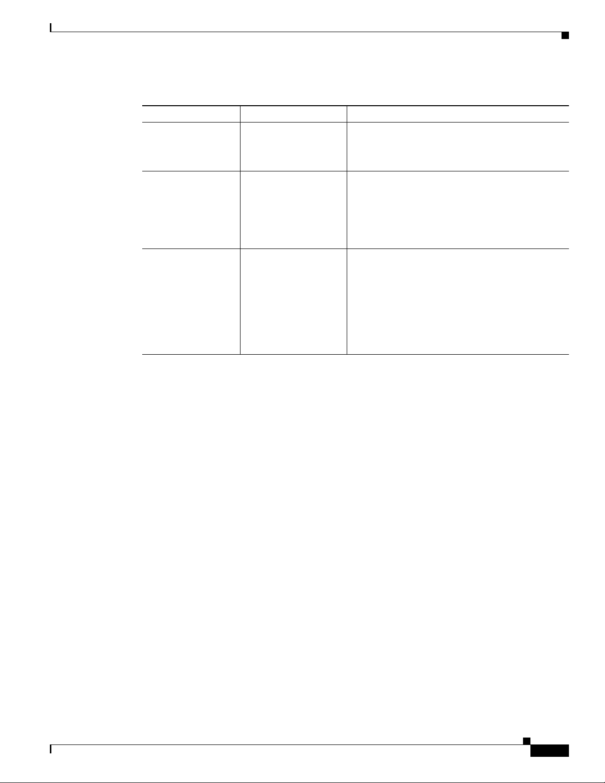
Table 1 PFC3/DFC3 Operating Restrictions
PFC Version DFC Version Restrictions
PFC3A DFC3A No restrictions.
DFC3B The DFC3B functions as a DFC3A.
DFC3BXL The DFC3BXL functions as a DFC3A.
PFC3B DFC3A You must reset the system after installing a
DFC3A-equipped module.
The PFC3B functions as a PFC3A.
DFC3B No restrictions.
DFC3BXL The DFC3BXL functions as a DFC3B.
PFC3BXL DFC3A You must reset the system after installing a
DFC3A-equipped module.
The PFC3BXL functions as a PFC3A.
DFC3B You must reset the system after installing a
DFC3B-equipped module.
The PFC3BXL functions as a PFC3B.
DFC3BXL No restrictions.
Safety Overview
Safety warnings appear throughout this publication in procedures that, if performed incorrectly, may
harm you. A warning symbol precedes each warning statement.
78-15893-06
Catalyst 6500 Series DFC3A, DFC3B, and DFC3BXL Installation Note
3
Page 4

Safety Overview
Statement 1071—Warning Definition
Warning
Waarschuwing
Varoitus
IMPORTANT SAFETY INSTRUCTIONS
This warning symbol means danger. You are in a situation that could cause bodily injury. Before you
work on any equipment, be aware of the hazards involved with electrical circuitry and be familiar
with standard practices for preventing accidents. Use the statement number provided at the end of
each warning to locate its translation in the translated safety warnings that accompanied this
device.
SAVE THESE INSTRUCTIONS
BELANGRIJKE VEILIGHEIDSINSTRUCTIES
Dit waarschuwingssymbool betekent gevaar. U verkeert in een situatie die lichamelijk letsel kan
veroorzaken. Voordat u aan enige apparatuur gaat werken, dient u zich bewust te zijn van de bij
elektrische schakelingen betrokken risico's en dient u op de hoogte te zijn van de standaard
praktijken om ongelukken te voorkomen. Gebruik het nummer van de verklaring onderaan de
waarschuwing als u een vertaling van de waarschuwing die bij het apparaat wordt geleverd, wilt
raadplegen.
BEWAAR DEZE INSTRUCTIES
TÄRKEITÄ TURVALLISUUSOHJEITA
Tämä varoitusmerkki merkitsee vaaraa. Tilanne voi aiheuttaa ruumiillisia vammoja. Ennen kuin
käsittelet laitteistoa, huomioi sähköpiirien käsittelemiseen liittyvät riskit ja tutustu
onnettomuuksien yleisiin ehkäisytapoihin. Turvallisuusvaroitusten käännökset löytyvät laitteen
mukana toimitettujen käännettyjen turvallisuusvaroitusten joukosta varoitusten lopussa näkyvien
lausuntonumeroiden avulla.
4
SÄILYTÄ NÄMÄ OHJEET
Attention
Catalyst 6500 Series DFC3A, DFC3B, and DFC3BXL Installation Note
IMPORTANTES INFORMATIONS DE SÉCURITÉ
Ce symbole d'avertissement indique un danger. Vous vous trouvez dans une situation pouvant
entraîner des blessures ou des dommages corporels. Avant de travailler sur un équipement, soyez
conscient des dangers liés aux circuits électriques et familiarisez-vous avec les procédures
couramment utilisées pour éviter les accidents. Pour prendre connaissance des traductions des
avertissements figurant dans les consignes de sécurité traduites qui accompagnent cet appareil,
référez-vous au numéro de l'instruction situé à la fin de chaque avertissement.
CONSERVEZ CES INFORMATIONS
78-15893-06
Page 5

Safety Overview
Warnung
Avvertenza
Advarsel
WICHTIGE SICHERHEITSHINWEISE
Dieses Warnsymbol bedeutet Gefahr. Sie befinden sich in einer Situation, die zu Verletzungen führen
kann. Machen Sie sich vor der Arbeit mit Geräten mit den Gefahren elektrischer Schaltungen und
den üblichen Verfahren zur Vorbeugung vor Unfällen vertraut. Suchen Sie mit der am Ende jeder
Warnung angegebenen Anweisungsnummer nach der jeweiligen Übersetzung in den übersetzten
Sicherheitshinweisen, die zusammen mit diesem Gerät ausgeliefert wurden.
BEWAHREN SIE DIESE HINWEISE GUT AUF.
IMPORTANTI ISTRUZIONI SULLA SICUREZZA
Questo simbolo di avvertenza indica un pericolo. La situazione potrebbe causare infortuni alle
persone. Prima di intervenire su qualsiasi apparecchiatura, occorre essere al corrente dei pericoli
relativi ai circuiti elettrici e conoscere le procedure standard per la prevenzione di incidenti.
Utilizzare il numero di istruzione presente alla fine di ciascuna avvertenza per individuare le
traduzioni delle avvertenze riportate in questo documento.
CONSERVARE QUESTE ISTRUZIONI
VIKTIGE SIKKERHETSINSTRUKSJONER
Dette advarselssymbolet betyr fare. Du er i en situasjon som kan føre til skade på person. Før du
begynner å arbeide med noe av utstyret, må du være oppmerksom på farene forbundet med
elektriske kretser, og kjenne til standardprosedyrer for å forhindre ulykker. Bruk nummeret i slutten
av hver advarsel for å finne oversettelsen i de oversatte sikkerhetsadvarslene som fulgte med denne
enheten.
Aviso
¡Advertencia!
TA VARE PÅ DISSE INSTRUKSJONENE
INSTRUÇÕES IMPORTANTES DE SEGURANÇA
Este símbolo de aviso significa perigo. Você está em uma situação que poderá ser causadora de
lesões corporais. Antes de iniciar a utilização de qualquer equipamento, tenha conhecimento dos
perigos envolvidos no manuseio de circuitos elétricos e familiarize-se com as práticas habituais de
prevenção de acidentes. Utilize o número da instrução fornecido ao final de cada aviso para
localizar sua tradução nos avisos de segurança traduzidos que acompanham este dispositivo.
GUARDE ESTAS INSTRUÇÕES
INSTRUCCIONES IMPORTANTES DE SEGURIDAD
Este símbolo de aviso indica peligro. Existe riesgo para su integridad física. Antes de manipular
cualquier equipo, considere los riesgos de la corriente eléctrica y familiarícese con los
procedimientos estándar de prevención de accidentes. Al final de cada advertencia encontrará el
número que le ayudará a encontrar el texto traducido en el apartado de traducciones que acompaña
a este dispositivo.
GUARDE ESTAS INSTRUCCIONES
78-15893-06
Catalyst 6500 Series DFC3A, DFC3B, and DFC3BXL Installation Note
5
Page 6
Safety Overview
Varning!
VIKTIGA SÄKERHETSANVISNINGAR
Denna varningssignal signalerar fara. Du befinner dig i en situation som kan leda till personskada.
Innan du utför arbete på någon utrustning måste du vara medveten om farorna med elkretsar och
känna till vanliga förfaranden för att förebygga olyckor. Använd det nummer som finns i slutet av
varje varning för att hitta dess översättning i de översatta säkerhetsvarningar som medföljer denna
anordning.
SPARA DESSA ANVISNINGAR
Catalyst 6500 Series DFC3A, DFC3B, and DFC3BXL Installation Note
6
78-15893-06
Page 7
Safety Overview
Aviso
Advarsel
INSTRUÇÕES IMPORTANTES DE SEGURANÇA
Este símbolo de aviso significa perigo. Você se encontra em uma situação em que há risco de lesões
corporais. Antes de trabalhar com qualquer equipamento, esteja ciente dos riscos que envolvem os
circuitos elétricos e familiarize-se com as práticas padrão de prevenção de acidentes. Use o
número da declaração fornecido ao final de cada aviso para localizar sua tradução nos avisos de
segurança traduzidos que acompanham o dispositivo.
GUARDE ESTAS INSTRUÇÕES
VIGTIGE SIKKERHEDSANVISNINGER
Dette advarselssymbol betyder fare. Du befinder dig i en situation med risiko for
legemesbeskadigelse. Før du begynder arbejde på udstyr, skal du være opmærksom på de
involverede risici, der er ved elektriske kredsløb, og du skal sætte dig ind i standardprocedurer til
undgåelse af ulykker. Brug erklæringsnummeret efter hver advarsel for at finde oversættelsen i de
oversatte advarsler, der fulgte med denne enhed.
GEM DISSE ANVISNINGER
78-15893-06
Catalyst 6500 Series DFC3A, DFC3B, and DFC3BXL Installation Note
7
Page 8
Safety Overview
Catalyst 6500 Series DFC3A, DFC3B, and DFC3BXL Installation Note
8
78-15893-06
Page 9
Required Tools and Parts
Warning
Warning
Only trained and qualified personnel should be allowed to install, replace, or service this equipment.
Statement 1030
Hazardous voltage or energy is present on the backplane when the system is operating. Use caution
when servicing.
Statement 1034
Required Tools and Parts
These parts are included in the DFC3 daughter card upgrade kit:
• The DFC3A, DFC3B, or DFC3BXL daughter card
• Installation bracket and mounting hardware (mounts over the male standoffs at the rear of the DFC
daughter card)
• One disposable grounding wrist strap
• One MEM-XCEF720-1GB memory upgrade
Note The MEM-XCEF720-1GB memory upgrade is required for the DFC3BXL upgrade only and is included
as part of the DFC3BXL daughter card kit only.
78-15893-06
Catalyst 6500 Series DFC3A, DFC3B, and DFC3BXL Installation Note
9
Page 10

Removing a CFC or DFC Daughter Card
These tools and supplies are required to remove and install the DFC3 daughter card:
• Antistatic mat or foam pad to support the removed module and an antistatic bag to store the removed
Central Forwarding Card (CFC) or DFC daughter card
• Your own ESD-prevention equipment or the disposable grounding wrist strap included in the
upgrade kit
• Number 1 Phillips-head screwdriver for the DFC daughter card installation hardware
Removing a CFC or DFC Daughter Card
If your module has either a CFC or a DFC daughter card installed, you must remove the daughter card
before installing the new DFC daughter card. Two procedures are provided: See either the “Removing
the CFC Daughter Card” section on page 10 or “Removing the DFC3 Daughter Card from Modules
Without Stiffener Brackets” section on page 13.
Removing the CFC Daughter Card
To remove a CFC daughter card, follow these steps:
Warning
Step 1 Attach an ESD grounding strap to your wrist and to ground. (If you are unsure about the correct way to
Step 2 Remove the Ethernet module from the Catalyst 6500 series switch. (If you are unsure about the correct
Step 3 Place the Ethernet module on an antistatic mat with the front of the module facing toward you.
Step 4 Use a Phillips-head screwdriver to remove the three securing screws and the two cap nuts.
During this procedure, wear grounding wrist straps to avoid ESD damage to the card. Do not directly
touch the backplane with your hand or any metal tool, or you could shock yourself.
attach an ESD grounding strap, refer to the “Attaching Your ESD Grounding Strap” section on page 40
for instructions.)
procedure for removing a module from the switch chassis, refer to the “Removing and Installing
Modules in the Chassis” section on page 32 for removal instructions.)
(See Figure 1.)
Statement 94
10
Catalyst 6500 Series DFC3A, DFC3B, and DFC3BXL Installation Note
78-15893-06
Page 11
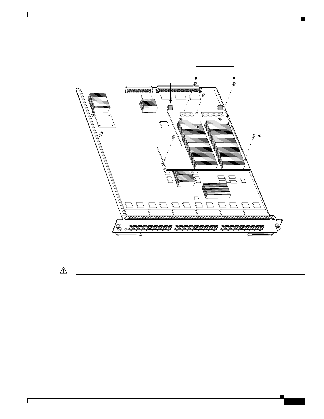
Figure 1 CFC Daughter Card Securing Screws and Cap Nuts
Cap nuts (2)
Card removal
tabs (2)
Removing a CFC or DFC Daughter Card
CFC daughter card
Heat sinks
Screws (3)
WS-X5530
O
24P
P
F
-S
6724
-X
S
W
S
U
T
A
T
S
123
IG
G
T
R
N
R
E
TH
IT E
B
A
FP
T - S
E
45678
9101112131415
16
71181920212223
24
99714
Step 5
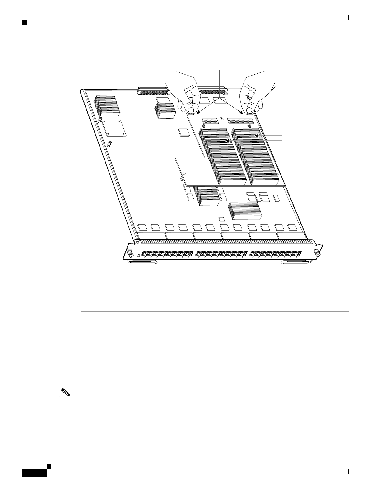
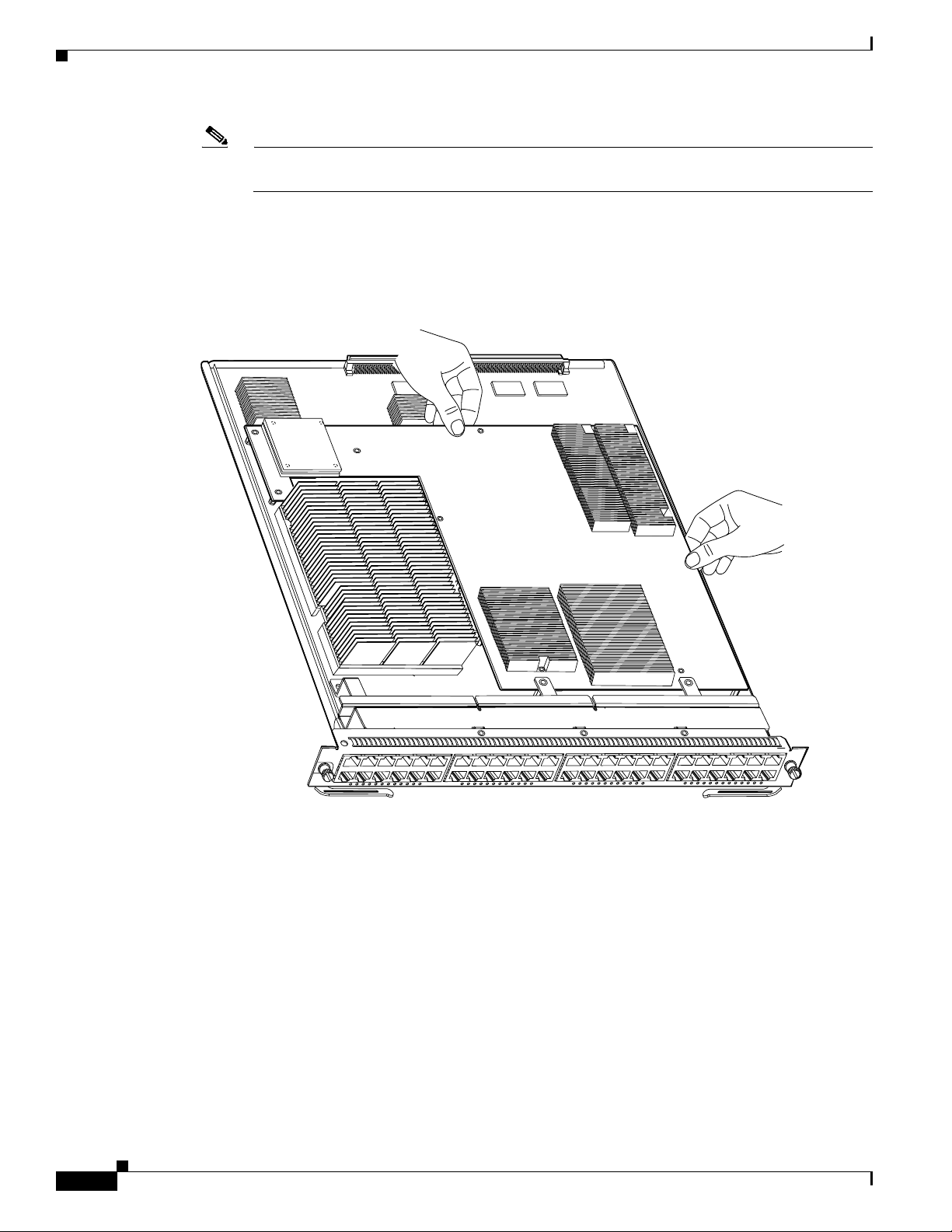
To unseat the CFC daughter card from the Ethernet module, hold each tab at the rear of the CFC daughter
card between your thumb and index finger, and gently press down on both tabs until the connectors are
unseated. (See Figure 2.)
Caution Do not apply too much pressure on the tabs. Applying too much pressure on the tabs can cause damage
to the module.
78-15893-06
Catalyst 6500 Series DFC3A, DFC3B, and DFC3BXL Installation Note
11
Page 12
Removing the DFC3 Daughter Card
Figure 2 Unseating the CFC Daughter Card Connectors
Heat sinks
Step 6
WS-X5530
O
24P
P
F
4-S
672
-X
S
W
S
U
T
TA
S
1234567
Gently lift the CFC daughter card with both hands and remove the CFC daughter card from the module.
FP
- S
T
E
N
R
E
TH
E
IT
B
A
IG
G
T
R
8
Step 7 Place the CFC daughter card on an antistatic mat, antistatic foam pad, or in an antistatic bag.
Step 8 Proceed to the “Installing the DFC3 Daughter Card” section on page 23.
Removing the DFC3 Daughter Card
This section contains two DFC3 daughter card removal procedures. One procedure covers how to remove
the DFC3 daughter card from modules that are not equipped with a stiffener bracket. A second procedure
is included that covers how to remove the DFC daughter card from early versions of the
WS-X6748-GE-TX Ethernet module that are equipped with a stiffener bracket.
Note Only the WS-X6748-GE-TX Ethernet module might be equipped with a stiffener bracket.
9
101112131415
1671
1819202122
2324
120046
12
Catalyst 6500 Series DFC3A, DFC3B, and DFC3BXL Installation Note
78-15893-06
Page 13
Removing the DFC3 Daughter Card
Removing the DFC3 Daughter Card from Modules Without Stiffener Brackets
To remove the DFC3 daughter card from modules that are not equipped with a stiffener bracket, follow
these steps:
Warning
During this procedure, wear grounding wrist straps to avoid ESD damage to the card. Do not directly
touch the backplane with your hand or any metal tool, or you could shock yourself.
Statement 94
Step 1 Attach an ESD grounding strap to your wrist and to ground. (If you are unsure about the correct way to
attach an ESD grounding strap, refer tothe “Attaching Your ESD Grounding Strap” section on page 40
for instructions.)
Step 2 Remove the Ethernet module from the Catalyst 6500 series switch. (If you are unsure about the correct
procedure for removing a module from the switch chassis, refer to the “Removing and Installing
Modules in the Chassis” section on page 32 for removal instructions.)
Step 3 Place the Ethernet module on an antistatic mat with the front of the module facing toward you.
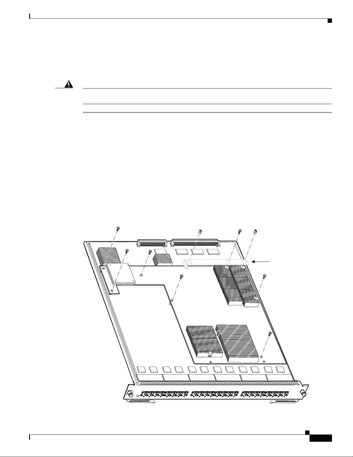
Step 4 If your DFC daughter card has a small metal installation bracket as shown in Figure 3, use a No.1
Phillips-head screwdriver to remove the two cap nuts and the one screw securing the bracket. Set them
aside with the bracket. If there is no bracket, just remove the two cap nuts and the one screw.
Step 5 Remove the remaining securing screws. (See Figure 3.)
Figure 3 Removing the DFC Daughter Card Securing Screws and Cap Nuts
WS-X5530
Installation
bracket. May
or may not
be present.
FP
T - S
E
N
R
E
H
T
E
IT
B
A
IG
G
T
R
O
24P
P
F
6724-S
-X
S
W
S
U
T
A
T
S
123
45678
9101112131415
1671181920
212223
24
154456
78-15893-06
Catalyst 6500 Series DFC3A, DFC3B, and DFC3BXL Installation Note
13
Page 14
Removing the DFC3 Daughter Card
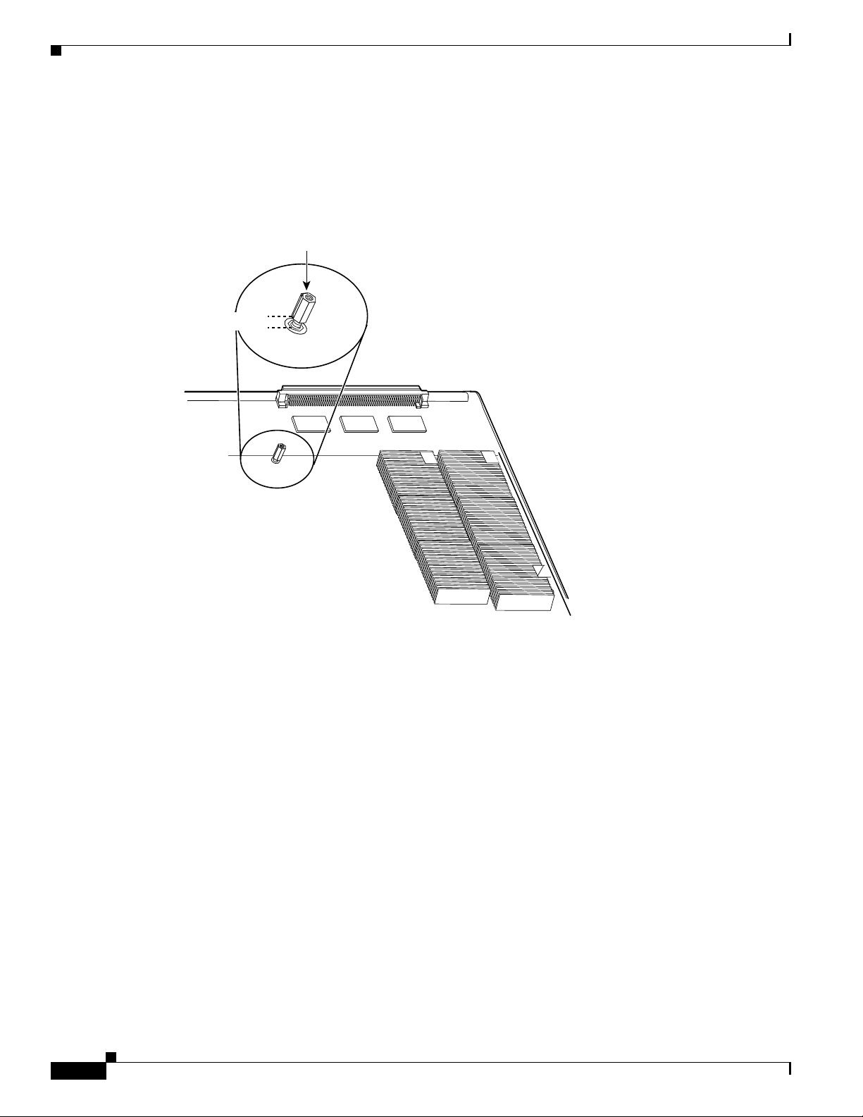
Step 6 Partially reinstall the cap nut, as shown in Figure 4, about 3 turns so that there is a space of about 1/8
inch (3 mm) between the bottom of the cap nut and the top of the DFC3 daughter card. The cap nut acts
as a stop when you unseat the daughter card connector so that the DFC3 daughter card does not move
horizontally and cause damage to the base board.
Figure 4 Partially Installing the Cap Nut
Appx 1/8 inch
Cap nut
120047
Step 7 With your left hand, lift slightly at the location shown in Figure 5. While lifting with your left hand, rock
the DFC3 daughter card up and down with your right hand, no more than half an inch in either direction,
to unseat the DFC3 daughter card from the module.
14
Catalyst 6500 Series DFC3A, DFC3B, and DFC3BXL Installation Note
78-15893-06
Page 15
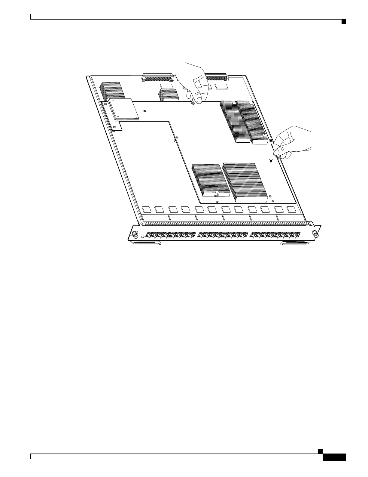
Figure 5 Unseat the DFC3 Daughter Card from the Module
Lift here
Rock up
and down
Removing the DFC3 Daughter Card
Step 8
WS-X5530
24P
P
F
6724-S
-X
S
W
S
TU
TA
S
Remove the one cap nut.
O
123
IG
G
T
R
N
R
E
H
T
E
IT
B
A
FP
- S
T
E
45678
910111213
1415
16
711819
2021
2223
24
120048
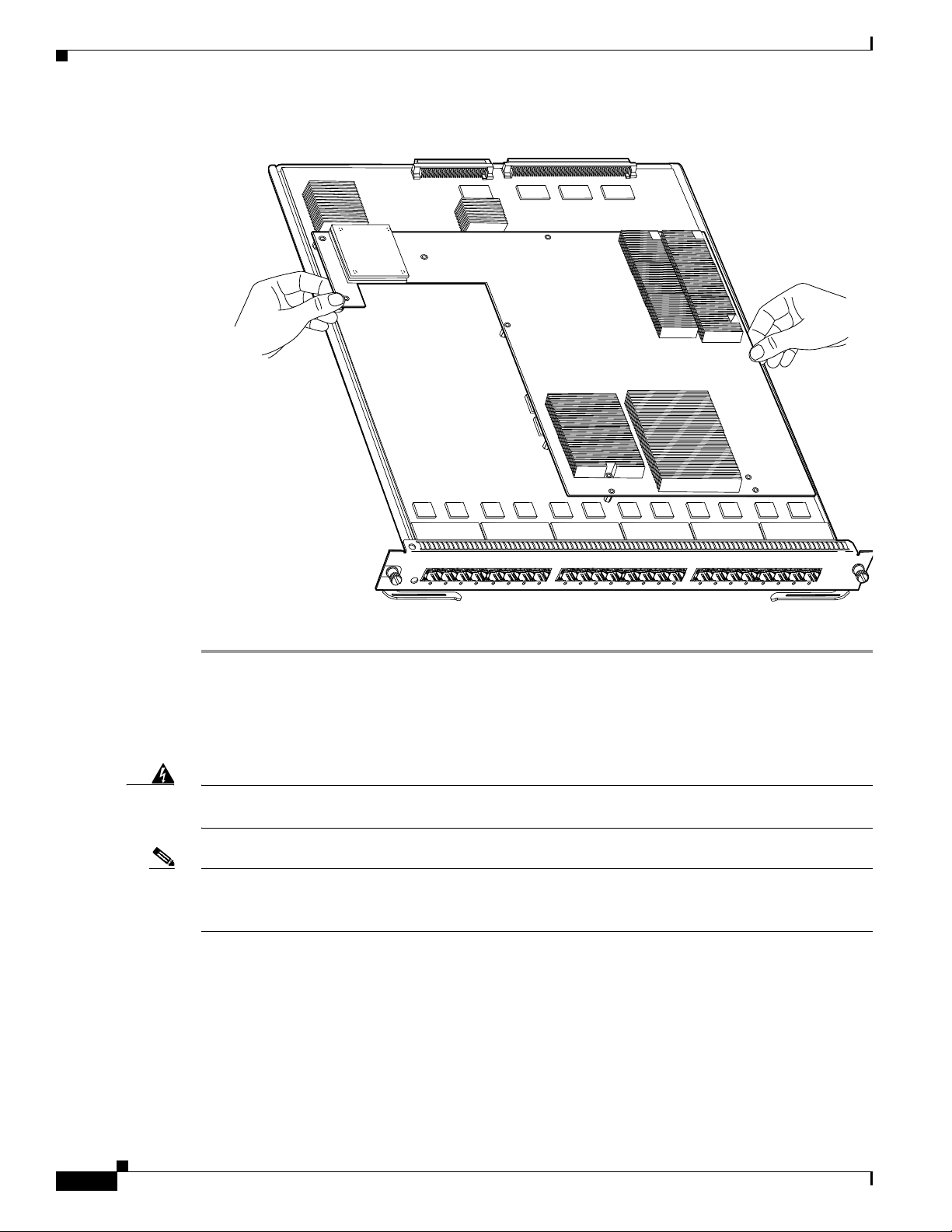
Step 9 Holding the DFC3 daughter card with both hands, gently lift it straight up from the module. (See
Figure 6.) Immediately place the DFC3 daughter card on an antistatic mat, antistatic foam pad, or in an
antistatic bag.
78-15893-06
Catalyst 6500 Series DFC3A, DFC3B, and DFC3BXL Installation Note
15
Page 16
Removing the DFC3 Daughter Card
Figure 6 Removing the DFC3 Daughter Card from the Module
Unseat the
DFC power
connector
Lift here
Lift here
WS-X5530
24P
FP
6724-S
-X
S
W
S
U
T
TA
S
IT E
B
A
IG
G
T
R
O
123
FP
- S
T
E
N
R
E
TH
45678
9101112131415
167118
1920
21222324
Removing the DFC3 Daughter Card from Modules Equipped with
a Stiffener Bracket
Warning
Note Some early versions of the WS-X6748-GE-TX Ethernet modules have a stiffener bracket mounted across
During this procedure, wear grounding wrist straps to avoid ESD damage to the card. Do not directly
touch the backplane with your hand or any metal tool, or you could shock yourself.
Statement 94
the top front part of the module. A modified procedure to remove the DFC daughter card from
WS-X6748-GE-TX Ethernet modules equipped with a stiffener bracket is included.
16
Catalyst 6500 Series DFC3A, DFC3B, and DFC3BXL Installation Note
78-15893-06
Page 17

Removing the DFC3 Daughter Card
To remove a DFC3 daughter card from a WS-X6748-GE-TX Ethernet module equipped with a stiffener
bracket, follow these steps:
Step 1 Attach an ESD grounding strap to your wrist and to ground. (If you are unsure about the correct way to
attach an ESD grounding strap, refer to the “Attaching Your ESD Grounding Strap” section on page 40
for instructions.)
Step 2 Remove the WS-X6748-GE-TX Ethernet module from the Catalyst 6500 series switch. (If you are
unsure about the correct procedure for removing a module from the switch chassis, refer to the
“Removing and Installing Modules in the Chassis” section on page 32 for removal instructions.)
Step 3 Place the module on an antistatic mat or foam with the front of the module facing toward you.
Step 4 If your DFC daughter card has a small metal installation bracket as shown in Figure 7, use a No.1
Phillips-head screwdriver to remove the two cap nuts and the one screw securing the bracket. Set them
aside with the bracket. If there is no installation bracket, remove the two cap nuts and the one screw.
Step 5 Use a Phillips-head screwdriver to remove the remaining securing screws. (See Figure 7.)
Figure 7 Removing the Securing Screws and Cap Nuts (WS-X6748-GE-TX Equipped with a
Front Stiffener Bracket)
Stiffener
bracket
WS-X5530
WS-X6748-GE-TX 48 PORT ETHERNET
Installation
bracket. May
or may not
be present
130149
Stiffener bracket tabs, DFC
daughter card mounted
underneath tabs.
78-15893-06
Catalyst 6500 Series DFC3A, DFC3B, and DFC3BXL Installation Note
17
Page 18
Removing the DFC3 Daughter Card
Note The two screws securing the DFC3 daughter card that pass through the front stiffener bracket
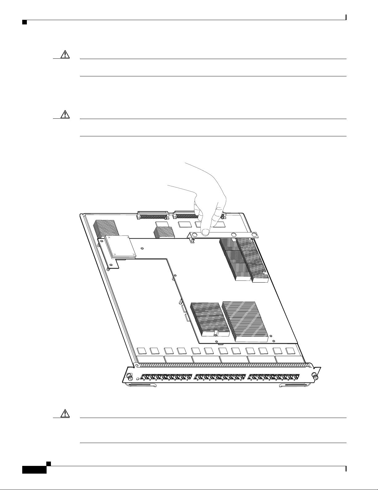
Step 6 With your left hand, lift slightly at the location shown in Figure 8, and gently rock the DFC3 daughter
card up and down to unseat the daughter card from the module connectors.
Figure 8 Unseating the DFC Connectors (WS-X6748-GE-TX Equipped with a Front Stiffener
tabs are longer than the remaining DFC installation screws.
Bracket)
Lift here
Step 7
Lift
here
WS-X5530
WS-X6748-GE-TX 48 PORT ETHERNET
130150
Holding the DFC3 daughter card with both hands, carefully lift the back end of the DFC3 daughter card
up slightly to clear the module connectors, and then carefully slide the DFC3 daughter card out from
under the two front stiffener bracket tabs. Lift the DFC3 daughter card straight up from the module (see
Figure 9) and immediately place the removed DFC3 daughter card on an antistatic mat, antistatic foam
pad, or in an antistatic bag.
18
Catalyst 6500 Series DFC3A, DFC3B, and DFC3BXL Installation Note
78-15893-06
Page 19

Upgrading the DFC3BXL Daughter Card Memory
Figure 9 Removing the DFC3 Daughter Card (WS-X6748-GE-TX Equipped with a Front Stiffener
Bracket)
Lift here to
unseat DFC
power connector
Stiffener
bracket
WS-X5530
WS-X6748-GE-TX 48 PORT ETHERNET
Stiffener bracket tabs
Upgrading the DFC3BXL Daughter Card Memory
Upgrading your module with a DFC3BXL daughter card requires that you also install a 1-GB memory
upgrade (part number MEM-XCEF720-1GB) that comes with your DFC3BXL upgrade kit. This
memory upgrade is installed on the module in a small outline dual inline memory module (SODIMM)
chip socket located underneath the DFC daughter card. You should install the memory upgrade while the
CFC or the DFC daughter card is removed from the module and before you install the DFC3BXL
daughter card upgrade.
130151
78-15893-06
Catalyst 6500 Series DFC3A, DFC3B, and DFC3BXL Installation Note
19
Page 20

Upgrading the DFC3BXL Daughter Card Memory
Removing the SODIMM
Warning
During this procedure, wear grounding wrist straps to avoid ESD damage to the card. Do not directly
touch the backplane with your hand or any metal tool, or you could shock yourself.
Statement 94
To remove the existing SODIMM, follow these steps:
Step 1 Attach an ESD grounding strap to your wrist and to ground. (If you are unsure about the correct way to
attach an ESD grounding strap, refer to the “Attaching Your ESD Grounding Strap” section on page 40
for instructions.)
Step 2 Locate the SODIMM on the module. (See Figure 10.)
Figure 10 Location of SODIMM on a WS-X67xx Module
WS-X5530
T G
R
O
24P
FP
6724-S
-X
S
W
S
U
T
TA
S
1234567
DDR SDRAM
SODIMM
FP
- S
T
E
N
R
E
TH
IT E
B
A
IG
8
9101112131415
16
71181920212223
24
113340
20
Catalyst 6500 Series DFC3A, DFC3B, and DFC3BXL Installation Note
78-15893-06
Page 21

Upgrading the DFC3BXL Daughter Card Memory
Step 3 Release the spring clips from the SODIMM, and release the SODIMM from the socket. (See Figure 11.)
Figure 11 Releasing the SODIMM Spring Clips
Pull the tabs away with
your thumbs, bracing your
forefingers against the
rails. The memory module
will be released. Then raise
the memory module to
a vertical position.
Memory module
51543
Step 4 When both ends of the SODIMM are released from the socket, grasp the ends of the SODIMM with your
thumb and forefinger, and pull the SODIMM completely out of the socket.
Caution SODIMMs are sensitive components that are susceptible to ESD damage. To prevent ESD damage,
handle SODIMMs by the edges only; avoid touching the memory modules, pins, or traces (the metal
fingers along the connector edge of the SODIMM). (See Figure 12.)
78-15893-06
Catalyst 6500 Series DFC3A, DFC3B, and DFC3BXL Installation Note
21
Page 22

Upgrading the DFC3BXL Daughter Card Memory
Figure 12 Handling a SODIMM
Step 5 Immediately place the old SODIMM in an antistatic bag to protect it from ESD damage.
Installing the SODIMM
51544
Caution SODIMMs are sensitive components that are susceptible to ESD damage. To prevent ESD damage,
handle SODIMMs by the edges only; avoid touching the memory modules, pins, or traces (the metal
fingers along the connector edge of the SODIMM). (See Figure 12.)
To install the 1-GB SODIMM, follow these steps:
Step 1 Remove a new SODIMM from the antistatic shipping bag.
Step 2 Hold the SODIMM with the component side up and with the connector edge (the metal fingers) away
from you.
Step 3 Hold the sides of the SODIMM between your thumbs and forefingers. (See Figure 12.)
Step 4 Tilt the SODIMM to approximately the same angle as the socket, and insert the connector edge into the
socket.
Caution When inserting SODIMMs, use firm but not excessive pressure. If you damage a socket, you will have
to return the DFC to the factory for repair.
Step 5 Press the SODIMM down until it is secured by the spring clips. (See Figure 13.)
22
Catalyst 6500 Series DFC3A, DFC3B, and DFC3BXL Installation Note
78-15893-06
Page 23

Figure 13 Installing the SODIMM
28736
Installing the DFC3 Daughter Card
Step 6
When the SODIMM is installed, check the two alignment holes, and ensure that the spring retainer is
visible. If it is not, the SODIMM is not seated properly. If any SODIMM appears misaligned, carefully
remove it and reseat it in the socket. Push the SODIMM firmly back into the socket until the retainer
springs snap into place.
Installing the DFC3 Daughter Card
This section contains two DFC3 installation procedures. One procedure covers installing the DFC3
daughter card on modules that are not equipped with stiffener brackets. A second procedure is included
that covers installing the DFC daughter cards on WS-X6748-GE-TX modules that are equipped with
stiffener brackets.
Installing the DFC3 Daughter Card on Modules Without Stiffener Brackets
To install the DFC3 on modules that do not have stiffener brackets, follow these steps:
Warning
During this procedure, wear grounding wrist straps to avoid ESD damage to the card. Do not directly
touch the backplane with your hand or any metal tool, or you could shock yourself.
Statement 94
78-15893-06
Step 1 Attach an ESD grounding strap to your wrist and to ground. (If you are unsure about the correct way to
attach an ESD grounding strap, refer to the “Attaching Your ESD Grounding Strap” section on page 40
for instructions.)
Step 2 Remove the new DFC3 from the antistatic bag and the installation hardware from the bag.
Note The DFC3 daughter card is designed to be installed on different modules; therefore, there may
be more mounting holes on the DFC3 daughter card than there are standoffs on the module. Not
all mounting holes on the DFC3 daughter card will be used in all installations. Visually verify
that there are standoffs beneath the mounting holes before installing the securing screws.
Step 3 Align the mounting holes on the DFC3 daughter card (see Figure 14) with the male standoffs on the
module. (See Figure 15.) Make sure that the remaining mounting holes on the DFC3 daughter card are
aligned with the remaining standoffs on the module.
Catalyst 6500 Series DFC3A, DFC3B, and DFC3BXL Installation Note
23
Page 24

Installing the DFC3 Daughter Card
Figure 14 Mounting Holes on the DFC3 Daughter Card
Align with the male standoffs
on the module
99361
99361
Figure 15 Male Standoff Locations on the WS-X67xx Modules
Male standoffs
24
WS-X5530
24P
FP
6724-S
-X
S
W
S
U
T
A
T
S
123
T G
R
O
E
TH
IT E
B
A
IG
FP
- S
T
E
N
R
45678
Catalyst 6500 Series DFC3A, DFC3B, and DFC3BXL Installation Note
9101112131415
16
71181920212223
24
99716
78-15893-06
Page 25

Installing the DFC3 Daughter Card
Step 4 Ensure that the connectors on the DFC3 are aligned with the connectors on the module. Figure 16 shows
the connectors on the underside of the DFC3.
Figure 16 DFC3 Daughter Card Connectors (Underside of DFC Daughter Card Shown)
Connectors
99363
Step 5
Apply pressure to the area shown in Figure 17 to seat the power connector.
Figure 17 Seating the Power Connector
Apply pressure here to seat power connector
78-15893-06
WS-X5530
P
F
- S
T
E
N
R
E
H
T
E
IT
B
A
IG
G
T
R
O
24P
P
F
6724-S
-X
S
W
S
TU
A
T
S
123
45678
9101112131415
16
71181920212223
24
99718
Catalyst 6500 Series DFC3A, DFC3B, and DFC3BXL Installation Note
25
Page 26
Installing the DFC3 Daughter Card
Caution Use care not to damage the connectors on the module. If you damage a connector, it will be necessary
to return the module to Cisco for repair.
Step 6 Position the installation bracket over the two male standoffs at the back of the DFC daughter card. Apply
pressure to the top of the bracket, as shown in Figure 18 to fully seat the DFC3 daughter card on the
module.
Caution When seating the DFC daughter card, do not apply pressure to any other location on the DFC daughter
card, especially the heat sinks.
Figure 18 Seating the DFC3 Daughter Card on the Module
Apply pressure to bracket.
to seat DFC connectors.
Do not press on heat sinks.
26
Step 7
WS-X5530
R
O
24P
P
F
6724-S
-X
S
W
S
TU
TA
S
123
Use a Phillips-head screwdriver to install the securing screws and the two cap nuts. (See Figure 19.)
IT
B
A
IG
G
T
P
F
T - S
E
N
R
E
TH
E
45678
9101112131415
16
71181920212223
24
99717
Caution Yo u must install screws in all available standoffs. The screws provide grounding between the DFC3
daughter card and the module. Failure to install all of the screws will invalidate the safety approvals and
pose a risk of fire and electrical hazard.
Catalyst 6500 Series DFC3A, DFC3B, and DFC3BXL Installation Note
78-15893-06
Page 27

Installing the DFC3 Daughter Card
Note You should visually verify that there are standoffs beneath the mounting holes before installing the
securing screws.
Figure 19 Installing the Securing Screws and Cap Nuts
Step 8
WS-X5530
O
24P
FP
6724-S
-X
S
W
S
U
AT
T
S
1234567
FP
- S
T
E
N
R
E
H
T
IT E
B
A
IG
G
T
R
8
9101112131415
16
71181920212223
24
99719
Reinstall the Ethernet module in the chassis. (If you are unsure on the correct procedure for installing a
module in the switch chassis, refer to the “Removing and Installing Modules in the Chassis” section on
page 32 for installation instructions.)
78-15893-06
Catalyst 6500 Series DFC3A, DFC3B, and DFC3BXL Installation Note
27
Page 28

Installing the DFC3 Daughter Card
Installing the DFC3 Daughter Card on Modules Equipped with a Stiffener Bracket
Note Some early versions of the WS-X6748-GE-TX Ethernet modules have a stiffener bracket mounted across
the top front part of the module, which requires a modified procedure to install the DFC daughter card.
Warning
During this procedure, wear grounding wrist straps to avoid ESD damage to the card. Do not directly
touch the backplane with your hand or any metal tool, or you could shock yourself.
Statement 94
To install the DFC daughter card on a WS-X6748-GE-TX Ethernet module that is equipped with a
stiffener bracket, follow these steps:
Step 1 Attach an ESD grounding strap to your wrist and to ground. (If you are unsure about the correct way to
attach an ESD grounding strap, refer to “Attaching Your ESD Grounding Strap” section on page 40 for
instructions.)
Step 2 Remove the new DFC3 daughter card from the antistatic bag and the installation hardware from the bag.
Note The DFC3 daughter card is designed to be installed on different modules; therefore, there may
be more mounting holes on the DFC3 daughter card than there are standoffs on the module. Not
all mounting holes on the DFC3 daughter card will be used in all installations. Visually verify
that there are standoffs beneath the mounting holes before installing the securing screws.
Step 3 Position the DFC3 daughter card over the module, and slightly tilt the DFC3 daughter card so that the
back end will clear the module connectors.
Step 4 Carefully slide the DFC3 under the two stiffener bracket tabs. (See Figure 20.) Verify that the DFC
daughter card is under the two stiffener bracket tabs.
28
Caution You must position the DFC daughter card under the two stiffener bracket tabs. If you install the DFC
daughter card above the two stiffener bracket tabs, you can permanently damage the DFC daughter card.
Step 5 Align the mounting holes on the DFC3 daughter card with the male standoffs on the module. (See
Figure 20.) Make sure that the remaining mounting holes on the DFC3 daughter card are aligned with
the remaining standoffs.
Note You should visually verify that there are standoffs beneath the mounting holes before installing
the securing screws.
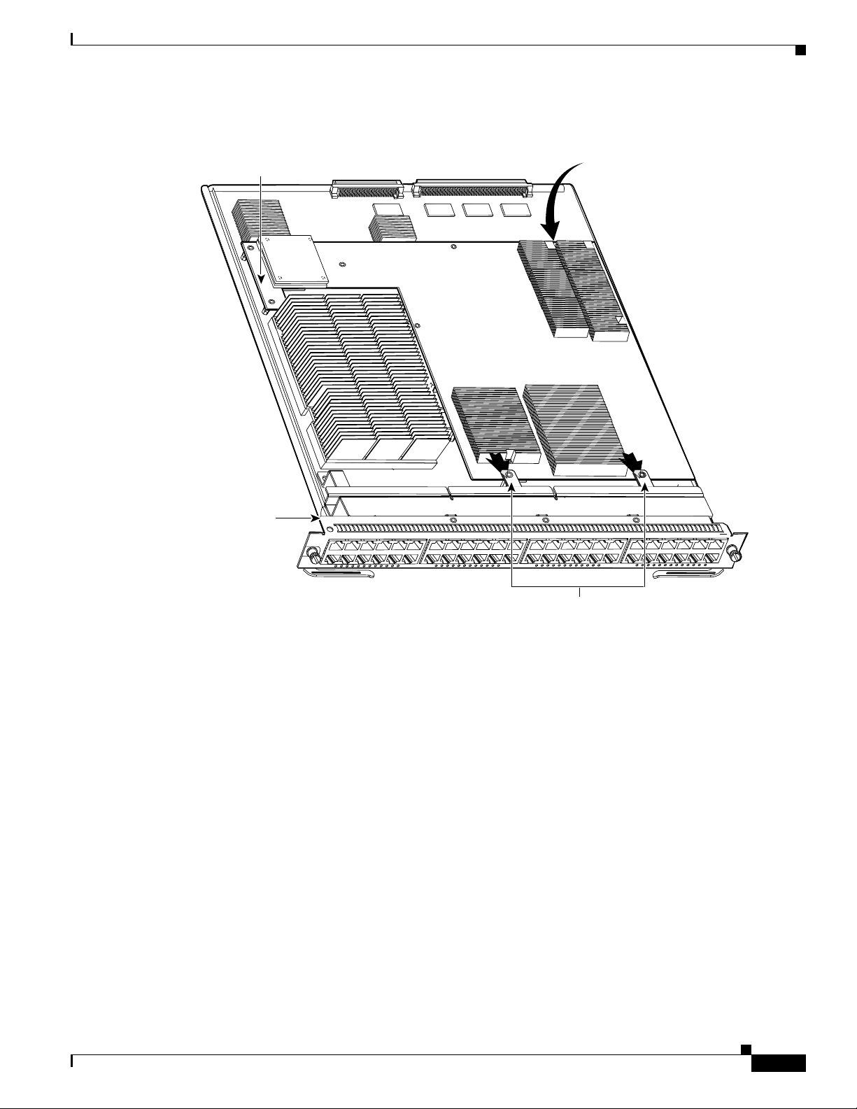
Step 6 Press down on the edge of the DFC3 daughter card (see Figure 20) to seat the DFC3 daughter card power
connector to the module power connector.
Catalyst 6500 Series DFC3A, DFC3B, and DFC3BXL Installation Note
78-15893-06
Page 29
Installing the DFC3 Daughter Card
Figure 20 Seating the DFC Daughter Card Power Connector (WS-X6748-GE-TX Equipped with a
Front Stiffener Bracket)
Apply pressure to seat DFC daughter card power connector
Stiffener
bracket
WS-X5530
WS-X6748-GE-TX 48 PORT ETHERNET
130152
Stiffener bracket tabs. DFC
daughter card slides
underneath tabs.
78-15893-06
Catalyst 6500 Series DFC3A, DFC3B, and DFC3BXL Installation Note
29
Page 30

Installing the DFC3 Daughter Card
Step 7 Position the installation bracket over the two standoffs and press down on the top of the bracket to seat
the DFC3 daughter card connectors on the module connectors. (See Figure 21.)
Caution When seating the DFC3 daughter card on the module connectors, DO NOT touch or apply any pressure
to the heat sinks. Press down on the installation bracket only.
Figure 21 Seating the DFC3 on the Module (WS-X6748-GE-TX Equipped with a Front Stiffener
Bracket)
Apply pressure to seat
DFC connectors. Do
not press on heat sinks
30
WS-X5530
WS-X6748-GE-TX 48 PORT ETHERNET
130153
Step 8
Secure the DFC3 daughter card to the module through the stiffener bracket with the two long screws that
you previously removed.
Step 9 Continue installing the remainder of the screws and the cap nuts to fully attach the DFC3 daughter card
to the module. (See Figure 22.)
Caution Do not overtighten the screws and the cap nuts because you will damage the board.
Catalyst 6500 Series DFC3A, DFC3B, and DFC3BXL Installation Note
78-15893-06
Page 31

Installing the DFC3 Daughter Card
Figure 22 Installing the Screws and Cap Nuts (WS-X6748-GE-TX Equipped with a Front Stiffener
Bracket)
Installation
bracket
Stiffener
bracket
WS-X5530
WS-X6748-GE-TX 48 PORT ETHERNET
154457
Stiffener bracket tabs. DFC
daughter card must be installed
underneath tabs.
Caution Yo u must install screws in all available standoffs. The screws provide grounding between the DFC3
daughter card and the module. Failure to install all screws will invalidate the safety approvals and pose
a risk of fire and electrical hazard.
Step 10 Reinstall the Ethernet module in the chassis. (If you are unsure about the correct procedure for installing
a module in the switch chassis, refer to the “Removing and Installing Modules in the Chassis” section
on page 32 for installation instructions.)
78-15893-06
Catalyst 6500 Series DFC3A, DFC3B, and DFC3BXL Installation Note
31
Page 32

Removing and Installing Modules in the Chassis
Removing and Installing Modules in the Chassis
This section describes how to correctly remove and install a module in a Catalyst 6500 series switch
chassis slot.
Caution During this procedure, wear grounding wrist straps to avoid ESD damage to the card.
Warning
Invisible laser radiation may be emitted from disconnected fibers or connectors. Do not stare into
beams or view directly with optical instruments.
Removing a Module from the Chassis
To remove a module from the chassis, perform these steps:
Step 1 Disconnect any network interface cables or console port cables attached to the module.
Step 2 Attach an ESD grounding strap to your wrist and to ground. (If you are unsure about the correct way to
attach an ESD grounding strap, refer to the “Attaching Your ESD Grounding Strap” section on page 40
for instructions.)
Step 3 Verify that the captive installation screws on all of the modules in the chassis are tight. This step assures
that the space created by the removed module is maintained.
Note If the captive installation screws are loose, the electromagnetic interference (EMI) gaskets on
the installed modules will push the modules toward the open slot, reducing the opening size and
making it difficult to reinstall the module.
Step 4 Loosen the two captive installation screws on the module.
Statement 272
32
Catalyst 6500 Series DFC3A, DFC3B, and DFC3BXL Installation Note
78-15893-06
Page 33

Removing and Installing Modules in the Chassis
Step 5 Depending on the orientation of the slots in the chassis (horizontal or vertical), perform one of the
following two sets of substeps:
Horizontal slots
a. Place your thumbs on the left and right ejector levers, and simultaneously rotate the levers outward
to unseat the module from the backplane connector.
b. Grasp the front edge of the module and slide the module part of the way out of the slot. Place your
other hand under the module to support the weight of the module. Do not touch the module circuitry.
Vertical slots
a. Place your thumbs on the ejector levers located at the top and bottom of the module, and
simultaneously rotate the levers outward to unseat the module from the backplane connector.
b. Grasp the edges of the module, and slide the module straight out of the slot. Do not touch the module
circuitry.
Step 6 Place the module on an antistatic mat or antistatic foam.
Installing a Module in the Chassis
Caution To prevent ESD damage, handle modules by the carrier edges only and wear grounding wrist straps.
Warning
Step 1 Attach an ESD grounding strap to your wrist and to ground. (If you are unsure about the correct way to
Step 2 Verify that the captive installation screws are tightened on all modules installed in the chassis. This
Invisible laser radiation may be emitted from disconnected fibers or connectors. Do not stare into
beams or view directly with optical instruments.
To install a module in the chassis, perform these steps:
attach an ESD grounding strap, refer to the “Attaching Your ESD Grounding Strap” section on page 40
for instructions.)
assures that the EMI gaskets on all modules are fully compressed in order to maximize the opening space
for the new module or the replacement module.
Note If the captive installation screws are loose, the EMI gaskets on the installed modules will push
adjacent modules toward the open slot, reducing the opening size and making it difficult to
reinstall the module.
Statement 1051
78-15893-06
Step 3 Fully open both ejector levers on the module. (See Figure 23.)
Catalyst 6500 Series DFC3A, DFC3B, and DFC3BXL Installation Note
33
Page 34

Removing and Installing Modules in the Chassis
Step 4 Depending on the orientation of the slots in the chassis (horizontal or vertical), perform one of the
following two sets of substeps:
Horizontal slots
a. Position the module in the slot. (See Figure 23.) Make sure that you align the sides of the module
carrier with the slot guides on each side of the slot.
b. Carefully slide the module into the slot until the EMI gasket along the top edge of the module makes
contact with the module in the slot above it and both ejector levers have closed to approximately 45
degrees with respect to the module faceplate. (See Figure 24.)
c. Using the thumb and forefinger of each hand, grasp the two ejector levers and press down to create
a small (0.040 inch [1 mm]) gap between the module’s EMI gasket and the module above it. (See
Figure 24.)
Caution Do not press down too hard on the levers. They will bend and be damaged.
d. While gently pressing down, simultaneously close the left and right ejector levers to fully seat the
module in the backplane connector. The ejector levers are fully closed when they are flush with the
module faceplate. (See Figure 25.)
Note Failure to fully seat the module in the backplane connector can result in error messages.
e. Tighten the two captive installation screws on the module.
Note Make sure that the ejector levers are fully closed before tightening the captive installation
screws.
f. Verify that the module STATUS LED is lit. Check the STATUS LED periodically. If the STATUS
LED changes from orange to green, the module has successfully completed the boot process and is
now online. If the STATUS LED remains orange or turns red, the module has not successfully
completed the boot process and may have encountered an error.
34
Catalyst 6500 Series DFC3A, DFC3B, and DFC3BXL Installation Note
78-15893-06
Page 35

Removing and Installing Modules in the Chassis
4
3
5
5
4
6
6
Figure 23 Positioning the Module in a Horizontal Slot Chassis
Insert module
between slot guides
FAN
STATUS
EMI gasket
1
2
3
4
5
6
EMI gasket
WS-X6748-GE-TX 48 PORT ETHERNET
o
INPUT
FAN
OUTPUT
OK
OK
FAIL
o
INPUT
FAN
OUTPUT
OK
OK
FAIL
154230
Ejector lever fully
extended
78-15893-06
Catalyst 6500 Series DFC3A, DFC3B, and DFC3BXL Installation Note
35
Page 36

Removing and Installing Modules in the Chassis
4
3
5
5
4
6
6
Figure 24 Clearing the EMI Gasket in a Horizontal Slot Chassis
1
2
3
Press down
4
W
S-X6224
FAN
STATUS
5
24
P
O
6
Press down
R
T
1
00
F
X
WS-X6748-GE-TX 48 PORT ETHERNET
1 mm
Gap between the module
EMI gasket and the
module above it
Figure 25 Ejector Lever Closure in a Horizontal Slot Chassis
1
2
3
4
FAN
STATUS
5
6
Ejector levers flush
with module faceplate
154231
154232
36
Catalyst 6500 Series DFC3A, DFC3B, and DFC3BXL Installation Note
78-15893-06
Page 37

Removing and Installing Modules in the Chassis
Vertical slots
a. Position the module in the slot. (See Figure 26.) Make sure that you align the sides of the module
carrier with the slot guides on the top and bottom of the slot.
b. Carefully slide the module into the slot until the EMI gasket along the right edge of the module
makes contact with the module in the slot adjacent to it and both ejector levers have closed to
approximately 45 degrees with respect to the module faceplate. (See Figure 27.)
c. Using the thumb and forefinger of each hand, grasp the two ejector levers and exert a slight pressure
to the left, deflecting the module approximately 0.040 inches (1 mm) to create a small gap between
the module’s EMI gasket and the module adjacent to it. (See Figure 27.)
Caution Do not exert too much pressure on the ejector levers. They will bend and be damaged.
d. While gently pressing on the ejector levers, simultaneously close them to fully seat the module in
the backplane connector. The ejector levers are fully closed when they are flush with the module
faceplate. (See Figure 28.)
e. Tighten the two captive installation screws on the module.
Note Make sure that the ejector levers are fully closed before tightening the captive installation
screws.
f. Verify that the module STATUS LED is lit. Check the STATUS LED periodically. If the STATUS
LED changes from orange to green, the module has successfully completed the boot process and is
now online. If the STATUS LED remains orange or turns red, the module has not successfully
completed the boot process and may have encountered an error.
78-15893-06
Catalyst 6500 Series DFC3A, DFC3B, and DFC3BXL Installation Note
37
Page 38

Removing and Installing Modules in the Chassis
4
3
6
Figure 26 Positioning the Module in a Vertical Slot Chassis
Ejector lever fully
extended
FAN
STATUS
WS-X6748-GE-TX 48 PORT ETHERNET
EMI
gasket
EMI
gasket
o
INPUT
o
FAN
OUTPUT
OK
OK
FAIL
INPUT
FAN
OUTPUT
OK
OK
FAIL
Insert module
between slot guides
154233
38
Catalyst 6500 Series DFC3A, DFC3B, and DFC3BXL Installation Note
78-15893-06
Page 39

Removing and Installing Modules in the Chassis
Figure 27 Clearing the EMI Gasket in a Vertical Slot Chassis
Gap between the module
EMI gasket and the
module above it
FAN
STATUS
Press left
1 mm
WS-X6748-G
E-TX 48 PO
RT ETHERNET
Press left
o
INPUT
o
FAN
OUTPUT
OK
OK
FAIL
INPUT
FAN
OUTPUT
OK
OK
FAIL
154234
78-15893-06
Catalyst 6500 Series DFC3A, DFC3B, and DFC3BXL Installation Note
39
Page 40

Attaching Your ESD Grounding Strap
Figure 28 Ejector Lever Closure in a Vertical Slot Chassis
F
AN
S
TA
T
US
All ejector levers flush
with module faceplate
Attaching Your ESD Grounding Strap
Electrostatic discharge (ESD) damage, which can occur when modules or other FRUs are improperly
handled, results in intermittent or complete failures. Modules consist of printed circuit boards that are
fixed in metal carriers. Electromagnetic interference (EMI) shielding and connectors are integral
components of the carrier. Although the metal carrier helps to protect the board from ESD, always use
an ESD grounding strap when handling modules.
Follow these guidelines for preventing ESD damage:
• Always use an ESD wrist strap and ensure that it makes maximum contact with bare skin. ESD
grounding straps are available with banana plugs, metal spring clips, or alligator clips. All
Catalyst 6500 series chassis are equipped with a banana plug connector (identified by the ground
symbol next to the connector) somewhere on the front panel. If you have an older Catalyst 6500
series chassis equipped with a plastic banana plug connector, we recommend that you use either the
supplied ESD grounding wrist strap (with a metal clip) or an ESD grounding wrist strap equipped
with an alligator clip. If you have a newer Catalyst 6500 series chassis that has a bare metal hole as
the banana plug connector (also identified by the ground symbol next to the connector), we
recommend that you use a personal ESD grounding strap equipped with a banana plug.
• If you choose to use the disposable ESD wrist strap supplied with most FRUs or an ESD wrist strap
equipped with an alligator clip, you must attach the system ground lug to the chassis in order to
provide a proper grounding point for the ESD wrist strap.
154235
40
Note This system ground is also referred to as the network equipment building system (NEBS)
ground.
Catalyst 6500 Series DFC3A, DFC3B, and DFC3BXL Installation Note
78-15893-06
Page 41

Attaching Your ESD Grounding Strap
• If your chassis does not have the system ground attached, you must install the system ground lug.
Refer to the online Catalyst 6500 Series Switches Installation Guide for the procedure.
Note You do not need to attach a supplemental system ground wire to the system ground lug; the
lug provides a direct path to the bare metal of the chassis
After you install the system ground lug, follow these steps to correctly attach the ESD wrist strap:
Step 1 Attach the ESD wrist strap to bare skin as follows:
a. If you are using the ESD wrist strap supplied with the FRUs, open the wrist strap package and
unwrap the ESD wrist strap. Place the black conductive loop over your wrist and tighten the strap
so that it makes good contact with your bare skin.
b. If you are using an ESD wrist strap equipped with an alligator clip, open the package and remove
the ESD wrist strap. Locate the end of the wrist strap that attaches to your body and secure it to your
bare skin.
Step 2 Grasp the spring or alligator clip on the ESD wrist strap and momentarily touch the clip to a bare metal
spot (unpainted surface) on the rack. We recommend that you touch the clip to an unpainted rack rail so
that any built-up static charge is then safely dissipated to the entire rack.
Step 3 Attach either the spring clip or the alligator clip to the ground lug screw as follows (See Figure 29):
a. If you are using the ESD wrist strap that is supplied with the FRUs, squeeze the spring clip jaws
open, position the spring clip to one side of the system ground lug screw head, and slide the spring
clip over the lug screw head so that the spring clip jaws close behind the lug screw head.
Note The spring clip jaws do not open wide enough to fit directly over the head of the lug screw
or the lug barrel.
b. If you are using an ESD wrist strap that is equipped with an alligator clip, attach the alligator clip
directly over the head of the system ground lug screw or to the system ground lug barrel.
78-15893-06
Catalyst 6500 Series DFC3A, DFC3B, and DFC3BXL Installation Note
41
Page 42

Attaching Your ESD Grounding Strap
Figure 29 Attaching the ESD Wrist Strap Clip to the System Ground Lug Screw
Clip
ESD ground
strap
W
S
-X
6K
-S
U
P
T
S
S
U
P
E
R
V
IS
O
R
O
S
M
-4
O
4
P
O
R
T
O
O
S
M
-
4
O
4
P
O
R
T
O
Grounding lug
Screw
CT
E
V
I
T
C
R
A
X
T
X
R
R
E
I
M
R
R
R
A
A
L
C
A
E
V
I
T
C
R
A
X
T
X
R
R
E
I
M
R
R
R
A
A
L
C
A
Side view of
grounding lug
S
witch Load
100%
1%
E
X
X
IV
T
T
X
C
R
A
X
T
X
R
2
T
R
E
R
I
O
M
R
P
R
R
A
A
O
L
C
P
A
E
X
V
X
I
T
T
X
C
R
A
X
T
X
R
2
T
R
E
R
I
O
M
R
P
R
R
A
A
O
L
C
P
A
System ground
connector
P
O
R
T 1
P
O
RT
K
IN
L
X
T
3
T
R
E
R
I
R
R
A
A
L
C
A
X
T
3
T
R
E
R
I
R
R
A
A
L
C
A
2
K
IN
L
E
IV
T
X
C
X
R
A
T
X
T
X
R
4
M
T
R
R
O
P
E
V
I
T
X
C
X
R
A
T
X
T
X
R
4
M
T
R
R
O
P
144607
Slide clip
behind screw
Clip installed
behind screw
2
-2
G
E
T
E
M
S
L
M
G
U
O
E
T
T
T
S
M
A
E
S
N
R
S
Y
O
W
E
S
C
P
R
C
O
N
SO
LE
P
O
RT
M
O
D
E
C
O
N
SO
LE
2
C
1
2
P
O
S
-S
I
1
S
U
T
A
T
S
C
-1
2
P
O
C
1
2
P
O
S
-S
S
U
T
A
T
S
C
-1
2
P
O
3
2
4
S
S
M
IR
K
K
N
I
K
N
L
I
1
2
L
IN
L
I
1
2
S
S
M
IR
3
3
4
K
K
N
I
K
N
L
I
1
N
2
L
I
L
3
P
CM
C
IA E
JE
E
V
I
T
X
C
X
R
A
T
X
T
X
T
R
E
S
E
R
R
E
1
I
M
R
T
R
R
R
A
A
O
L
C
P
A
K
N
I
4
L
E
V
I
T
X
C
X
R
A
T
X
T
X
T
R
E
S
E
R
R
E
1
I
M
R
T
R
R
R
A
A
O
L
C
P
A
K
N
I
4
L
42
In addition, follow these guidelines when handling modules:
• Handle carriers by available handles or edges only; avoid touching the printed circuit boards or
connectors.
• Place a removed component board-side-up on an antistatic surface or in a static shielding container.
If you plan to return the component to the factory, immediately place it in a static shielding
container.
• Never attempt to remove the printed circuit board from the metal carrier.
Caution For safety, periodically check the resistance value of the antistatic strap. The measurement should be
between 1 and 10 megohm (Mohm).
Catalyst 6500 Series DFC3A, DFC3B, and DFC3BXL Installation Note
78-15893-06
Page 43

Related Documentation
These documents are available for the Catalyst 6500 series switches:
• Regulatory Compliance and Safety Information for the Catalyst 6500 Series Switches
• Catalyst 6500 Series Switch Installation Guide
• Catalyst 6500 Series Switch Cisco IOS Software Configuration Guide
• Catalyst 6500 Series Switch Cisco IOS Command Reference
• Catalyst 6500 Series DFC Memory Installation Note
• Release Notes for Catalyst 6500 Series Switches
Obtaining Documentation
Cisco documentation and additional literature are available on Cisco.com. Cisco also provides several
ways to obtain technical assistance and other technical resources. These sections explain how to obtain
technical information from Cisco Systems.
Related Documentation
Cisco.com
You can access the most current Cisco documentation at this URL:
http://www.cisco.com/techsupport
You can access the Cisco website at this URL:
http://www.cisco.com
You can access international Cisco websites at this URL:
http://www.cisco.com/public/countries_languages.shtml
Product Documentation DVD
The Product Documentation DVD is a comprehensive library of technical product documentation on a
portable medium. The DVD enables you to access multiple versions of installation, configuration, and
command guides for Cisco hardware and software products. With the DVD, you have access to the same
HTML documentation that is found on the Cisco website without being connected to the Internet.
Certain products also have .PDF versions of the documentation available.
The Product Documentation DVD is available as a single unit or as a subscription. Registered Cisco.com
users (Cisco direct customers) can order a Product Documentation DVD (product number
DOC-DOCDVD= or DOC-DOCDVD=SUB) from Cisco Marketplace at this URL:
http://www.cisco.com/go/marketplace/
78-15893-06
Catalyst 6500 Series DFC3A, DFC3B, and DFC3BXL Installation Note
43
Page 44

Documentation Feedback
Ordering Documentation
Registered Cisco.com users may order Cisco documentation at the Product Documentation Store in the
Cisco Marketplace at this URL:
http://www.cisco.com/go/marketplace/
Nonregistered Cisco.com users can order technical documentation from 8:00 a.m. to 5:00 p.m.
(0800 to 1700) PDT by calling 1 866 463-3487 in the United States and Canada, or elsewhere by
calling 011 408 519-5055. You can also order documentation by e-mail at
tech-doc-store-mkpl@external.cisco.com or by fax at 1 408 519-5001 in the United States and Canada,
or elsewhere at 011 408 519-5001.
Documentation Feedback
You can rate and provide feedback about Cisco technical documents by completing the online feedback
form that appears with the technical documents on Cisco.com.
You can submit comments about Cisco documentation by using the response card (if present) behind the
front cover of your document or by writing to the following address:
Cisco Systems
Attn: Customer Document Ordering
170 West Tasman Drive
San Jose, CA 95134-9883
We appreciate your comments.
Cisco Product Security Overview
Cisco provides a free online Security Vulnerability Policy portal at this URL:
http://www.cisco.com/en/US/products/products_security_vulnerability_policy.html
From this site, you will find information about how to:
• Report security vulnerabilities in Cisco products.
• Obtain assistance with security incidents that involve Cisco products.
• Register to receive security information from Cisco.
A current list of security advisories, security notices, and security responses for Cisco products is
available at this URL:
http://www.cisco.com/go/psirt
To see security advisories, security notices, and security responses as they are updated in real time, you
can subscribe to the Product Security Incident Response Team Really Simple Syndication (PSIRT RSS)
feed. Information about how to subscribe to the PSIRT RSS feed is found at this URL:
http://www.cisco.com/en/US/products/products_psirt_rss_feed.html
44
Catalyst 6500 Series DFC3A, DFC3B, and DFC3BXL Installation Note
78-15893-06
Page 45

Reporting Security Problems in Cisco Products
Cisco is committed to delivering secure products. We test our products internally before we release them,
and we strive to correct all vulnerabilities quickly. If you think that you have identified a vulnerability
in a Cisco product, contact PSIRT:
• For Emergencies only— security-alert@cisco.com
An emergency is either a condition in which a system is under active attack or a condition for which
a severe and urgent security vulnerability should be reported. All other conditions are considered
nonemergencies.
• For Nonemergencies —psirt@cisco.com
In an emergency, you can also reach PSIRT by telephone:
• 1 877 228-7302
• 1 408 525-6532
Tip We encourage you to use Pretty Good Privacy (PGP) or a compatible product (for example, GnuPG) to
encrypt any sensitive information that you send to Cisco. PSIRT c a n work wi t h information that has been
encrypted with PGP versions 2.x through 9.x.
Obtaining Technical Assistance
Never use a revoked or an expired encryption key. The correct public key to use in your correspondence
with PSIRT is the one linked in the Contact Summary section of the Security Vulnerability Policy page
at this URL:
http://www.cisco.com/en/US/products/products_security_vulnerability_policy.html
The link on this page has the current PGP key ID in use.
If you do not have or use PGP, contact PSIRT at the aforementioned e-mail addresses or phone numbers
before sending any sensitive material to find other means of encrypting the data.
Obtaining Technical Assistance
Cisco Technical Support provides 24-hour-a-day award-winning technical assistance. The Cisco
Technical Support & Documentation website on Cisco.com features extensive online support resources.
In addition, if you have a valid Cisco service contract, Cisco Technical Assistance Center (TAC)
engineers provide telephone support. If you do not have a valid Cisco service contract, contact your
reseller.
78-15893-06
Catalyst 6500 Series DFC3A, DFC3B, and DFC3BXL Installation Note
45
Page 46

Obtaining Technical Assistance
Cisco Technical Support & Documentation Website
The Cisco Technical Support & Documentation website provides online documents and tools for
troubleshooting and resolving technical issues with Cisco products and technologies. The website is
available 24 hours a day, at this URL:
http://www.cisco.com/techsupport
Access to all tools on the Cisco Technical Support & Documentation website requires a Cisco.com user
ID and password. If you have a valid service contract but do not have a user ID or password, you can
register at this URL:
http://tools.cisco.com/RPF/register/register.do
Note Use the Cisco Product Identification (CPI) tool to locate your product serial number before submitting
a web or phone request for service. You can access the CPI tool from the Cisco Technical Support &
Documentation website by clicking the Tools & Resources link under Documentation & Tools. Choose
Cisco Product Identification Tool from the Alphabetical Index drop-down list, or click the Cisco
Product Identification Tool link under Alerts & RMAs. The CPI tool offers three search options: by
product ID or model name; by tree view; or for certain products, by copying and pasting show command
output. Search results show an illustration of your product with the serial number label location
highlighted. Locate the serial number label on your product and record the information before placing a
service call.
Submitting a Service Request
Using the online TAC Service Request Tool is the fastest way to open S3 and S4 service requests. (S3
and S4 service requests are those in which your network is minimally impaired or for which you require
product information.) After you describe your situation, the TAC Service Request Tool provides
recommended solutions. If your issue is not resolved using the recommended resources, your service
request is assigned to a Cisco engineer. The TAC Service Request Tool is located at this URL:
http://www.cisco.com/techsupport/servicerequest
For S1 or S2 service requests, or if you do not have Internet access, contact the Cisco TAC by telephone.
(S1 or S2 service requests are those in which your production network is down or severely degraded.)
Cisco engineers are assigned immediately to S1 and S2 service requests to help keep your business
operations running smoothly.
To open a service request by telephone, use one of the following numbers:
Asia-Pacific: +61 2 8446 7411 (Australia: 1 800 805 227)
EMEA: +32 2 704 55 55
USA: 1 800 553-2447
For a complete list of Cisco TAC contacts, go to this URL:
http://www.cisco.com/techsupport/contacts
46
Catalyst 6500 Series DFC3A, DFC3B, and DFC3BXL Installation Note
78-15893-06
Page 47

Obtaining Additional Publications and Information
Definitions of Service Request Severity
To ensure that all service requests are reported in a standard format, Cisco has established severity
definitions.
Severity 1 (S1)—An existing network is down, or there is a critical impact to your business operations.
You and Cisco will commit all necessary resources around the clock to resolve the situation.
Severity 2 (S2)—Operation of an existing network is severely degraded, or significant aspects of your
business operations are negatively affected by inadequate performance of Cisco products. You and Cisco
will commit full-time resources during normal business hours to resolve the situation.
Severity 3 (S3)—Operational performance of the network is impaired, while most business operations
remain functional. You and Cisco will commit resources during normal business hours to restore service
to satisfactory levels.
Severity 4 (S4)—You require information or assistance with Cisco product capabilities, installation, or
configuration. There is little or no effect on your business operations.
Obtaining Additional Publications and Information
Information about Cisco products, technologies, and network solutions is available from various online
and printed sources.
• The Cisco Product Quick Reference Guide is a handy, compact reference tool that includes brief
product overviews, key features, sample part numbers, and abbreviated technical specifications for
many Cisco products that are sold through channel partners. It is updated twice a year and includes
the latest Cisco offerings. To order and find out more about the Cisco Product Quick Reference
Guide, go to this URL:
http://www.cisco.com/go/guide
• Cisco Marketplace provides a variety of Cisco books, reference guides, documentation, and logo
merchandise. Visit Cisco Marketplace, the company store, at this URL:
http://www.cisco.com/go/marketplace/
• Cisco Press publishes a wide range of general networking, training and certification titles. Both new
and experienced users will benefit from these publications. For current Cisco Press titles and other
information, go to Cisco Press at this URL:
http://www.ciscopress.com
• Pack et magazine is the Cisco Systems technical user magazine for maximizing Internet and
networking investments. Each quarter, Packet delivers coverage of the latest industry trends,
technology breakthroughs, and Cisco products and solutions, as well as network deployment and
troubleshooting tips, configuration examples, customer case studies, certification and training
information, and links to scores of in-depth online resources. You can access Packet magazine at
this URL:
http://www.cisco.com/packet
78-15893-06
Catalyst 6500 Series DFC3A, DFC3B, and DFC3BXL Installation Note
47
Page 48

Obtaining Additional Publications and Information
• iQ Magazine is the quarterly publication from Cisco Systems designed to help growing companies
learn how they can use technology to increase revenue, streamline their business, and expand
services. The publication identifies the challenges facing these companies and the technologies to
help solve them, using real-world case studies and business strategies to help readers make sound
technology investment decisions. You can access iQ Magazine at this URL:
http://www.cisco.com/go/iqmagazine
or view the digital edition at this URL:
http://ciscoiq.texterity.com/ciscoiq/sample/
• Internet Protocol Journal is a quarterly journal published by Cisco Systems for engineering
professionals involved in designing, developing, and operating public and private internets and
intranets. You can access the Internet Protocol Journal at this URL:
http://www.cisco.com/ipj
• Networking products offered by Cisco Systems, as well as customer support services, can be
obtained at this URL:
http://www.cisco.com/en/US/products/index.html
• Networking Professionals Connection is an interactive website for networking professionals to share
questions, suggestions, and information about networking products and technologies with Cisco
experts and other networking professionals. Join a discussion at this URL:
http://www.cisco.com/discuss/networking
• World-class networking training is available from Cisco. You can view current offerings at
this URL:
http://www.cisco.com/en/US/learning/index.html
This document is to be used in conjunction with the documents listed in the “Related Documentation” section.
CCSP, CCVP, the Cisco Square Bridge logo, Follow Me Browsing, and StackWise are trademarks of Cisco Systems, Inc.; Changing the Way We
Work, Live, Play, and Learn, and iQuick Study are service marks of Cisco Systems, Inc.; and Access Registrar, Aironet, BPX, Catalyst, CCDA, CCDP,
CCIE, CCIP, CCNA, CCNP, Cisco, the Cisco Certified Internetwork Expert logo, Cisco IOS, Cisco Press, Cisco Systems, Cisco Systems Capital, the
Cisco Systems logo, Cisco Unity, Enterprise/Solver, EtherChannel, EtherFast, EtherSwitch, Fast Step, FormShare, GigaDrive, GigaStack, HomeLink,
Internet Quotient, IOS, IP/TV, iQ Expertise, the iQ logo, iQ Net Readiness Scorecard, LightStream, Linksys, MeetingPlace, MGX, the Networkers
logo, Networking Academy, Network Registrar, Pa cke t, PIX, Post-Routing, Pre-Routing, ProConnect, RateMUX, ScriptShare, SlideCast,
SMARTnet, The Fastest Way to Increase Your Internet Quotient, and TransPath are registered trademarks of Cisco Systems, Inc. and/or its affiliates
in the United States and certain other countries.
All other trademarks mentioned in this document or Website are the property of their respective owners. The use of the word partner does not imply
a partnership relationship between Cisco and any other company. (0601R)
© 2003–2006 Cisco Systems, Inc. All rights reserved.
48
Catalyst 6500 Series DFC3A, DFC3B, and DFC3BXL Installation Note
78-15893-06
 Loading...