

Page 1

4036168 Rev B
DDR2200 Series
Residential Gateway
Installation and Operation Guide
Page 2

Page 3

Please Read
Important
Please read this entire guide. If this guide provides installation or operation
instructions, give particular attention to all safety statements included in this guide.
Page 4

Notices
Tr ademark Acknowledgments
Cisco and the Cisco logo are trademarks or registered trademarks of Cisco and/or its
affiliates in the U.S. and other countries. A listing of Cisco's trademarks can be found
at www.cisco.com/go/trademarks.
HPNA is a trademark of the Home Phoneline Networking Alliance.
The Wi-Fi Protected Setup mark is a mark of the Wi-Fi Alliance. Wi-Fi Protected
Setup is a trademark of the Wi-Fi Alliance.
Other third party trademarks mentioned are the property of their respective owners.
The use of the word partner does not imply a partnership relationship between
Cisco and any other company. (1009R)
Disclaimer
The maximum performance for wireless is derived from IEEE Standard 802.11
specifications. Actual performance can vary, including lower wireless network
capacity, data throughput rate, range and coverage. Performance depends on many
factors, conditions and variables, including distance from the access point, volume of
network traffic, building materials and construction, operating system used, mix of
wireless products used, interference and other adverse conditions.
Publication Disclaimer
Cisco Systems, Inc. assumes no responsibility for errors or omissions that may
appear in this publication. We reserve the right to change this publication at any
time without notice. This document is not to be construed as conferring by
implication, estoppel, or otherwise any license or right under any copyright or
patent, whether or not the use of any information in this document employs an
invention claimed in any existing or later issued patent.
Copyright
© 2010, 2012 Cisco and/or its affiliates. All rights reserved. Printed in the United States of
America.
Information in this publication is subject to change without notice. No part of this
publication may be reproduced or transmitted in any form, by photocopy,
microfilm, xerography, or any other means, or incorporated into any information
retrieval system, electronic or mechanical, for any purpose, without the express
permission of Cisco Systems, Inc.
Page 5
Notice to Installers
The servicing instructions in this notice are for use by qualified service personnel only. To reduce the
risk of electric shock, do not perform any servicing other than that contained in the operating
instructions, unless you are qualified to do so.
Notice à l’attention des installateurs de réseaux câblés
Les instructions relatives aux interventions d’entretien, fournies dans la présente notice, s’adressent
exclusivement au personnel technique qualifié. Pour réduire les risques de chocs électriques, n’effectuer
aucune intervention autre que celles décrites dans le mode d'emploi et les instructions relatives au
fonctionnement, à moins que vous ne soyez qualifié pour ce faire.
Page 6
Mitteilung für CATV-Techniker
Die in dieser Mitteilung aufgeführten Wartungsanweisungen sind ausschließlich für qualifiziertes
Fachpersonal bestimmt. Um die Gefahr eines elektrischen Schlags zu reduzieren, sollten Sie keine
Wartungsarbeiten durchführen, die nicht ausdrücklich in der Bedienungsanleitung aufgeführt sind,
außer Sie sind zur Durchführung solcher Arbeiten qualifiziert.
Aviso a los instaladores de sistemas CATV
Las instrucciones de reparación contenidas en el presente aviso son para uso exclusivo por parte de
personal de mantenimiento cualificado. Con el fin de reducir el riesgo de descarga eléctrica, no realice
ninguna otra operación de reparación distinta a las contenidas en las instrucciones de funcionamiento, a
menos que posea la cualificación necesaria para hacerlo.
20080814_Installer800_Intl
Page 7

4036168 Rev B iii
Contents
IMPORTANT SAFETY INSTRUCTIONS vii
United States FCC Compliance x
CE Compliance xiii
About This Guide xvii
Chapter 1 Introducing the DDR2200 Series Residential Gateway 1
Benefits and Features .............................................................................................................. 2
What's On the Front Panel? .................................................................................................... 4
What's On the Back Panel? ..................................................................................................... 6
Chapter 2 Installing the Residential Gateway 9
Mounting the Residential Gateway Vertically ................................................................... 10
Mounting the Residential Gateway to the Wall ................................................................ 11
Connecting Your Computer to the Residential Gateway ................................................. 12
Connecting the DSL Interface .............................................................................................. 14
Connecting an IP Set-Top to the Gateway.......................................................................... 15
Chapter 3 Configuration and Operation 17
Logging In to the Residential Gateway .............................................................................. 19
System Summary ................................................................................................................... 21
Setting Up Your System with the Setup Wizard ............................................................... 22
Setting System Date and Time ............................................................................................. 26
Setting Password .................................................................................................................... 27
DHCP Leases .......................................................................................................................... 28
WAN Information .................................................................................................................. 29
Route Information .................................................................................................................. 30
ARP Information .................................................................................................................... 31
CPU Information .................................................................................................................... 32
Memory Information ............................................................................................................. 33
LAN Statistics ......................................................................................................................... 34
WAN Statistics ....................................................................................................................... 35
ATM Statistics ......................................................................................................................... 36
Page 8

Contents
iv 4036168 Rev B
Tools - Update Software ....................................................................................................... 37
Updating Software ................................................................................................................. 38
Settings Backup ...................................................................................................................... 40
Update Settings ...................................................................................................................... 42
Customer Configuration File ............................................................................................... 44
Restore Default Settings ........................................................................................................ 46
Saving the Configuration for the Residential Gateway .................................................... 48
Time Settings .......................................................................................................................... 50
Service Control ....................................................................................................................... 53
IP Access Control ................................................................................................................... 55
Password Access to the Residential Gateway .................................................................... 58
HTTP Server Port ................................................................................................................... 61
ALG Settings ........................................................................................................................... 63
System Log Configuration .................................................................................................... 65
System Logs ............................................................................................................................ 71
Print Server Settings .............................................................................................................. 73
Clone MAC Addresses .......................................................................................................... 76
Voice SIP Basic Configuration .............................................................................................. 79
Voice SIP Advanced Configuration .................................................................................... 84
USB File List ............................................................................................................................ 88
Chapter 4 DSL Configuration 91
DSL Summary ........................................................................................................................ 92
DSL Statistics .......................................................................................................................... 93
DSL Diagnostics ..................................................................................................................... 95
DSL Settings ............................................................................................................................ 98
ADSL Tone Settings ............................................................................................................. 104
Chapter 5 Home Network Configuration 107
Client Summary ................................................................................................................... 108
WAN Quick Setup ............................................................................................................... 112
LAN Setup ............................................................................................................................ 125
Wireless Summary ............................................................................................................... 130
Wireless Basic ....................................................................................................................... 131
Wireless Security .................................................................................................................. 140
Wireless MAC Filtering ...................................................................................................... 149
Wireless Bridge .................................................................................................................... 153
Wireless Station List ............................................................................................................ 155
Wi-Fi Protected Setup .......................................................................................................... 157
HPNA Information .............................................................................................................. 159
Page 9

Contents
4036168 Rev B v
Chapter 6 Security Configuration 165
MAC Filtering Setup ........................................................................................................... 166
Incoming IP Filtering ........................................................................................................... 174
Outgoing IP Filtering ........................................................................................................... 180
Parental Control Setup - Filtering Function ..................................................................... 185
URL Filtering Function ....................................................................................................... 191
Stateful Packet Inspection ................................................................................................... 196
Local Certificates .................................................................................................................. 199
Trusted CA Certificates ....................................................................................................... 204
Chapter 7 Advanced Configuration 207
Upstream Quality of Service .............................................................................................. 208
Remote Management ........................................................................................................... 212
Port Mapping ........................................................................................................................ 214
Virtual Servers Setup ........................................................................................................... 218
Port Triggering Setup .......................................................................................................... 222
DMZ Host Setup .................................................................................................................. 226
DNS Server Configuration .................................................................................................. 227
DNS Entries .......................................................................................................................... 228
Dynamic DNS ....................................................................................................................... 229
Nslookup ............................................................................................................................... 232
Default Gateway Routing ................................................................................................... 233
Static Route ........................................................................................................................... 235
Ping ........................................................................................................................................ 236
DHCP Server Probing ......................................................................................................... 238
Internet Group Management Protocol .............................................................................. 240
IPSec Settings ........................................................................................................................ 242
Chapter 8 Customer Information 245
Index 247
Page 10

Page 11

IMPORTANT SAFETY INSTRUCTIONS
4036168 Rev B vii
IMPORTANT SAFETY INSTRUCTIONS
Do not block any ventilation openings. Install in accordance with the manufacturer's
1) Read these instructions.
2) Keep these instructions.
3) Heed all warnings.
4) Follow all instructions.
5) Do not use this apparatus near water.
6) Clean only with dry cloth.
7)
instructions.
Do not install near any heat sources such as radiators, heat registers, stoves, or other
8)
apparatus (including amplifiers) that produce heat.
Do not defeat the safety purpose of the polarized or grounding-type plug. A
9)
polarized plug has two blades with one wider than the other. A grounding-type
plug has two blades and a third grounding prong. The wide blade or the third
prong are provided for your safety. If the provided plug does not fit into your
outlet, consult an electrician for replacement of the obsolete outlet.
Protect the power cord from being walked on or pinched particularly at plugs,
10)
convenience receptacles, and the point where they exit from the apparatus.
11) Only use attachments/accessories specified by the manufacturer.
12)
Unplug this apparatus during lightning storms or when unused for long periods of
13)
time.
Refer all servicing to qualified service personnel. Servicing is required when the
14)
apparatus has been damaged in any way, such as a power-supply cord or plug is
damaged, liquid has been spilled or objects have fallen into the apparatus, the
apparatus has been exposed to rain or moisture, does not operate normally, or has
been dropped.
Use only with the cart, stand, tripod, bracket, or table specified by the
manufacturer, or sold with the apparatus. When a cart is used, use caution
when moving the cart/apparatus combination to avoid injury from
tip-over.
Power Source W arning
A label on this product indicates the correct power source for this product. Operate this product only
from an electrical outlet with the voltage and frequency indicated on the product label. If you are
uncertain of the type of power supply to your home or business, consult your service provider or your
local power company.
The AC inlet on the unit must remain accessible and operable at all times.
Ground the Product
WARNING: Avoid electric shock and fire hazard! If this product connects to coaxial
cable wiring, be sure the cable system is grounded (earthed). Grounding provides
some protection against voltage surges and built-up static charges.
Page 12

IMPORTANT SAFETY INSTRUCTIONS
viii 4036168 Rev B
Protect the Product from Lightning
In addition to disconnecting the AC power from the wall outlet, disconnect the signal inputs.
V erify the Power Source from the On/Off Power Light
When the on/off power light is not illuminated, the apparatus may still be connected to the power
source. The light may go out when the apparatus is turned off, regardless of whether it is still plugged
into an AC power source.
Eliminate AC Mains Overloads
WARNING: Avoid electric shock and fire hazard! Do not overload AC mains, outlets,
extension cords, or integral convenience receptacles. For products that require battery
power or other power sources to operate them, refer to the operating instructions for
those products.
Provide Ventilation and Select a Location
Remove all packaging material before applying power to the product.
Do not place this apparatus on a bed, sofa, rug, or similar surface.
Do not place this apparatus on an unstable surface.
Do not install this apparatus in an enclosure, such as a bookcase or rack, unless the installation
provides proper ventilation.
Do not place entertainment devices (such as VCRs or DVDs), lamps, books, vases with liquids, or
other objects on top of this product.
Do not block ventilation openings.
Protect from Exposure to Moisture and Foreign Objects
WARNING: Avoid electric shock and fire hazard! Do not expose this product to
dripping or splashing liquids, rain, or moisture. Objects filled with liquids, such as
vases, should not be placed on this apparatus.
WARNING: Avoid electric shock and fire hazard! Unplug this product before cleaning.
Do not use a liquid cleaner or an aerosol cleaner. Do not use a magnetic/static cleaning
device (dust remover) to clean this product.
WARNING: Avoid electric shock and fire hazard! Never push objects through the
openings in this product. Foreign objects can cause electrical shorts that can result in
electric shock or fire.
Service Warnings
WARNING: Avoid electric shock! Do not open the cover of this product. Opening or
removing the cover may expose you to dangerous voltages. If you open the cover, your
warranty will be void. This product contains no user-serviceable parts.
Page 13

IMPORTANT SAFETY INSTRUCTIONS
4036168 Rev B ix
Check Product Safety
Upon completion of any service or repairs to this product, the service technician must perform safety
checks to determine that this product is in proper operating condition.
Protect the Product When Moving It
Always disconnect the power source when moving the apparatus or connecting or disconnecting
cables.
T elephone Equipment Notice
When using your telephone equipment, basic safety precautions should always be followed to reduce
the risk of fire, electric stock and injury to persons, including the following:
1. Do not use this product near water, for example, near a bath tub, wash bowl, kitchen sink or laundry
tub, in a wet basement or near a swimming pool.
2. Avoid using a telephone (other than a cordless type) during an electrical storm. There may be a
remote risk of electric shock from lightning.
3. Do not use the telephone to report a gas leak in the vicinity of the leak.
CAUTION: To reduce the risk of fire, use only No. 26 AWG or larger
telecommunication line cord.
SAVE THESE INSTRUCTIONS
20090915_Modem No Battery_Safety
Page 14

United States FCC Compliance
x 4036168 Rev B
United States FCC Compliance
This device has been tested and found to comply with the limits for a Class B digital device,
pursuant to part 15 of the FCC Rules. These limits are designed to provide reasonable
protection against such interference in a residential installation. This equipment generates,
uses, and can radiate radio frequency energy. If not installed and used in accordance with the
instructions, it may cause harmful interference to radio communications. However, there is
no guarantee that interference will not occur in a particular installation. If this equipment
does cause harmful interference to radio or television reception, which can be determined by
turning the equipment OFF and ON, the user is encouraged to try to correct the interference
by one or more of the following measures:
Reorient or relocate the receiving antenna.
Increase the separation between the equipment and receiver.
Connect the equipment into an outlet on a circuit different from that to which the
receiver is connected.
Consult the service provider or an experienced radio/television technician for help.
Any changes or modifications not expressly approved by Cisco Systems, Inc., could void the
user's authority to operate the equipment.
The information shown in the FCC Declaration of Conformity paragraph below is a
requirement of the FCC and is intended to supply you with information regarding the FCC
approval of this device. The phone numbers listed are for FCC-related questions only and not
intended for questions regarding the connection or operation for this device. Please contact your
service provider for any questions you may have regarding the operation or installation of this device.
Declaration of Conformity
This device complies with Part 15 of FCC
Rules. Operation is subject to the following
two conditions: 1) the device may not cause
harmful interference, and 2) the device must
accept any interference received, including
interference that may cause undesired
operation.
Canada EMI Regulation
This Class B digital apparatus complies with Canadian ICES-003.
Cet appareil numérique de la class B est conforme à la norme NMB-003 du Canada.
FCC Part 68
The Federal Communications Commission (FCC) of the United States restricts specific uses of
modems, and places registration responsibilities on both the manufacturer and the individual
user.
DDR2200 Residential Gateway
Model(s): DDR2200
Manufactured by:
Cisco Systems, Inc.
5030 Sugarloaf Parkway
Lawrenceville, Georgia 30044 USA
Telephone: 678-277-1120
Page 15

United States FCC Compliance
4036168 Rev B xi
1 The modem may not be connected to a party line or to a coin-operated telephone.
2 Notification to the telephone company is no longer required prior to connecting
registered equipment, but upon request from the telephone company, the user shall tell
the telephone company which line the equipment is connected to as well as the
registration number and ringer equivalence number of the registered protective circuitry.
FCC information is printed on a label on the bottom of the modem.
This equipment complies with Part 68 of FCC Rules and the requirements adopted by the
ACTA. On the base unit of this equipment is a label that contains, among other information,
a product identifier in the format US: US:GEMDL01BDDR2200. If requested, this number
must be provided to the telephone company.
The REN is useful to determine the quantity of devices you may connect to your telephone
line and still have those devices ring when your telephone number is called. In most, but not
all areas, the sum of the REN of all devices connected to one line should not exceed five (5.0).
To be certain of the number of devices you may connect to your line, as determined by the
REN, you should contact your local telephone company to determine the maximum REN for
your calling area.
If your equipment causes harm to the telephone network, the telephone company may
discontinue your service temporarily. If possible, they will notify you in advance. If advance
notice is not practical, you will be notified as soon as possible. You will be informed of your
right to file a complaint with the FCC. Your telephone company may make changes in its
facilities, equipment, operations or procedures that could affect the proper functioning of
your equipment. If they do, you will be notified in advance to give you an opportunity to
maintain uninterrupted telephone service.
If you experience trouble with this telephone equipment, please contact the service provider
for information on obtaining service or repairs.
The telephone company may ask that you disconnect this equipment from the network until
the problem has been corrected or until you are sure that the equipment is not
malfunctioning.
This equipment may not be used on coin service provided by the telephone company.
Connection to party lines is subject to state tariffs.
IC (Industry Canada) Notice
Notice: The Industry Canada (formerly Canadian Department of Communications) label
identifies certified equipment. This certification means that the equipment meets certain
telecommunications network protective, operational, and safety requirements. The
department does not guarantee the equipment will operate to the user's satisfaction.
Before installing this equipment, users should ensure that it is permissible to be connected to
the facilities of the local telecommunications company. The equipment must also be installed
using an acceptable method of connection. In some cases, the company's inside wiring
associated with a single-line individual service may be extended by means of a certified
connector assembly (telephone extension cord). The customer should be aware that
compliance with the above conditions may not prevent degradation of service in some
situations.
Page 16

United States FCC Compliance
xii 4036168 Rev B
Repairs to certified equipment should be made by an authorized Canadian maintenance
facility designated by the supplier. Any repairs or alterations made by the user may give the
telecommunications company cause to request the user to disconnect the equipment. Users
should ensure for their own protection that the electrical ground connections of the power
utility, telephone lines and internal metallic water pipe system, if present, are connected
together. This precaution may be particularly important in rural areas.
CAUTION:
Users should not attempt to make such connections themselves, but should
contact the appropriate electric inspection authority, or electrician, as
appropriate.
RF Exposure Statements
Note: This transmitter must not be co-located or operated in conjunction with any other
antenna or transmitter. This equipment should be installed and operated with a minimum
distance of 7.9 inches (20 cm) between the radiator and your body.
US
This system has been evaluated for RF exposure for humans in reference to ANSI C 95.1
(American National Standards Institute) limits. The evaluation was based in accordance with
FCC OET Bulletin 65C rev 01.01 in compliance with Part 2.1091 and Part 15.27. The minimum
separation distance from the antenna to general bystander is 7.9 inches (20 cm) to maintain
compliance.
Canada
This system has been evaluated for RF exposure for humans in reference to Canada Health
Code 6 (2009) limits. The evaluation was based on evaluation per RSS-102 Rev 4. The
minimum separation distance from the antenna to general bystander is 7.9 inches (20 cm) to
maintain compliance.
EU
This system has been evaluated for RF exposure for humans in reference to the ICNIRP
(International Commission on Non-Ionizing Radiation Protection) limits. The evaluation was
based on the EN 50385 Product Standard to Demonstrate Compliance of Radio Base Stations
and Fixed Terminals for Wireless Telecommunications Systems with basic restrictions or
reference levels related to Human Exposure to Radio Frequency Electromagnetic Fields from
300 MHz to 40 GHz. The minimum separation distance from the antenna to general
bystander is 20 cm (7.9 inches).
Australia
This system has been evaluated for RF exposure for humans as referenced in the Australian
Radiation Protection standard and has been evaluated to the ICNIRP (International
Commission on Non-Ionizing Radiation Protection) limits. The minimum separation distance
from the antenna to general bystander is 20 cm (7.9 inches).
20091016 FCC DSL_Dom and Intl
Page 17
CE Compliance
4036168 Rev B xiii
CE Compliance
Declaration of Conformity with Regard to the EU Directive 1999/5/EC (R&TTE Directive)
This declaration is only valid for configurations (combinations of software, firmware and
hardware) supported or provided by Cisco Systems for use within the EU. The use of
software or firmware not supported or provided by Cisco Systems may result in the
equipment no longer being compliant with the regulatory requirements.
Page 18

CE Compliance
xiv 4036168 Rev B
Note: The full declaration of conformity for this product can be found in the Declarations of
Conformity and Regulatory Information section of the appropriate product hardware
installation guide, which is available on Cisco.com.
The following standards were applied during the assessment of the product against the
requirements of the Directive 1999/5/EC:
Radio: EN 300 328
EMC: EN 301 489-1 and EN 301 489-17
Safety: EN 60950 and EN 50385
The CE mark and class-2 identifier are affixed to the product and its packaging. This product
conforms to the following European directives:
National Restrictions
This product is for indoor use only.
France
For 2.4 GHz, the output power is restricted to 10 mW EIRP when the product is used
outdoors in the band 2454 - 2483,5 MHz. There are no restrictions when used in other parts of
the 2,4 GHz band. Check http://www.arcep.fr/ for more details.
-1999/5/EC
Pour la bande 2,4 GHz, la puissance est limitée à 10 mW en p.i.r.e. pour les équipements
utilisés en extérieur dans la bande 2454 - 2483,5 MHz. Il n'y a pas de restrictions pour des
utilisations dans d'autres parties de la bande 2,4 GHz. Consultez http://www.arcep.fr/ pour
de plus amples détails.
Italy
This product meets the National Radio Interface and the requirements specified in the
National Frequency Allocation Table for Italy. Unless this wireless LAN product is operating
within the boundaries of the owner's property, its use requires a “general authorization.”
Please check http://www.comunicazioni.it/it/ for more details.
Questo prodotto è conforme alla specifiche di Interfaccia Radio Nazionali e rispetta il Piano
Nazionale di ripartizione delle frequenze in Italia. Se non viene installato all 'interno del
proprio fondo, l'utilizzo di prodotti Wireless LAN richiede una “Autorizzazione Generale”.
Consultare http://www.comunicazioni.it/it/ per maggiori dettagli.
Latvia
The outdoor usage of the 2.4 GHz band requires an authorization from the Electronic
Communications Office. Please check http://www.esd.lv for more details.
2,4 GHz frekvenču joslas izmantošanai ārpus telpām nepieciešama atļauja no Elektronisko
sakaru direkcijas. Vairāk informācijas: http://www.esd.lv.
Note: The regulatory limits for maximum output power are specified in EIRP. The EIRP level
of a device can be calculated by adding the gain of the antenna used (specified in dBi) to the
output power available at the connector (specified in dBm).
Page 19

CE Compliance
4036168 Rev B xv
Antennas
Use only the antenna supplied with the product.
20090312 CE_Gateway
Page 20

Page 21

About This Guide
4036168 Rev B xvii
About This Guide
Introduction
This installation and operation guide applies to the DDR2200 series residential
gateway. The DDR2200 series residential gateway connects to the DSL network in
your home to deliver data, video, voice, and wired (Ethernet) or wireless gateway
capabilities all from one device. Use this guide to install the residential gateway in
your home.
Purpose
This document provides the information you need to install and operate the
DDR2200 series residential gateway.
Audience
This guide is written for two audiences. Subscribers who have purchased a
residential gateway and want to experience high-speed Internet and high-quality
digital telephone service can use this guide for background information and basic
operation. This guide is also written for the service provider's installers who initially
set up and configure residential gateway in the subscriber's home. Most subscribers
will not want to use the more advanced functionality, and future releases of this
software will prevent subscriber access to these screens.
Document Version
This is the first formal release of this document.
Page 22

Page 23

4036168 Rev B 1
1 Chapter 1
Introducing the DDR2200
Series Residential Gateway
What's On the Back Panel? .................................................................... 6
Introduction
Imagine walking through your home and accessing the Internet from
nearly any room. The DDR2200 series residential gateway connects to
the DSL line in your home and to your home network to deliver data,
video, voice, and wired (Ethernet) or wireless gateway capabilities all
from one device. You can use your residential gateway to connect to a
variety of devices in the home or small office. The residential gateway
supports high-speed data access, VoIP services, and features that
support Internet Protocol TV (IPTV) deployment. Use this chapter to
learn about your residential gateway.
In This Chapter
Benefits and Features ............................................................................. 2
What's On the Front Panel? ................................................................... 4
Page 24

Chapter 1 Introducing the DDR2200 Series Residential Gateway
2 4036168 Rev B
Benefits and Features
Your residential gateway offers the following benefits and features:
Full routing functionality. The gateway router provides broadband transfer
speeds available between your home network and the service provider's network
for multi-user sharing. The high-performance router distributes data seamlessly
to all devices in the network without a noticeable effect to performance or speed.
True firewall capability. The gateway firewall includes both standard
NAT/PAT security and Stateful Packet inspection to defend against external
attacks.
High-quality data, voice, and IPTV services. The gateway combines an ADSL2+
bonded modem, 4-port Ethernet switch, Home Phoneline Networking Alliance
(HPNA™) 3.0 bridge and router functionality with optional VoIP and Wi-Fi into
one integrated platform.
Compact design. The gateway is compact enough to sit on a desktop and
versatile enough to be wall mounted in an out of the way location. The
residential gateway can also stand vertically.
Flexible networking. The gateway combines a variety of home networking
technologies in one box: Ethernet, USB, 802.11g wireless, and HPNA.
- Ethernet. Ethernet is a network standard for data transmission using either
coaxial or twisted pair cable over a LAN (local area network). The
information can be transmitted at speeds of 10 to 100 Mbps. If the home or
office is wired for Ethernet, use one of the four LAN interfaces on the
gateway to create a broadband network.
- USB. The USB port allows you to directly connect a computer or other
network capable device.
- 802.11g Wireless. The gateway includes an integrated wireless access point
that allows you to roam wirelessly throughout your home or office. With the
high-power wireless technology of the DDR2200, wireless "coldspots" are
virtually eliminated in the home.
- HPNA. The HPNA interface allows you to easily share digital services
throughout the home using the existing coaxial cable to distribute content
such as video, music, and games. HPNA offers the following benefits:
Multi-room DVR. Subscribers can record and share digital services
simultaneously in every room.
Multi-room gaming. Subscribers can access games from various locations
in the home and play simultaneously.
PC to TV. Subscribers can access data and video services over the HPNA
coaxial network throughout the home.
Page 25

Benefits and Features
4036168 Rev B 3
ADSL2+. Asymmetric Digital Subscriber Line (ADSL) provides high-access
transmission speeds for delivery of video, voice, and data services to homes over
ordinary copper telephone wire.
Page 26
Chapter 1 Introducing the DDR2200 Series Residential Gateway
4 4036168 Rev B
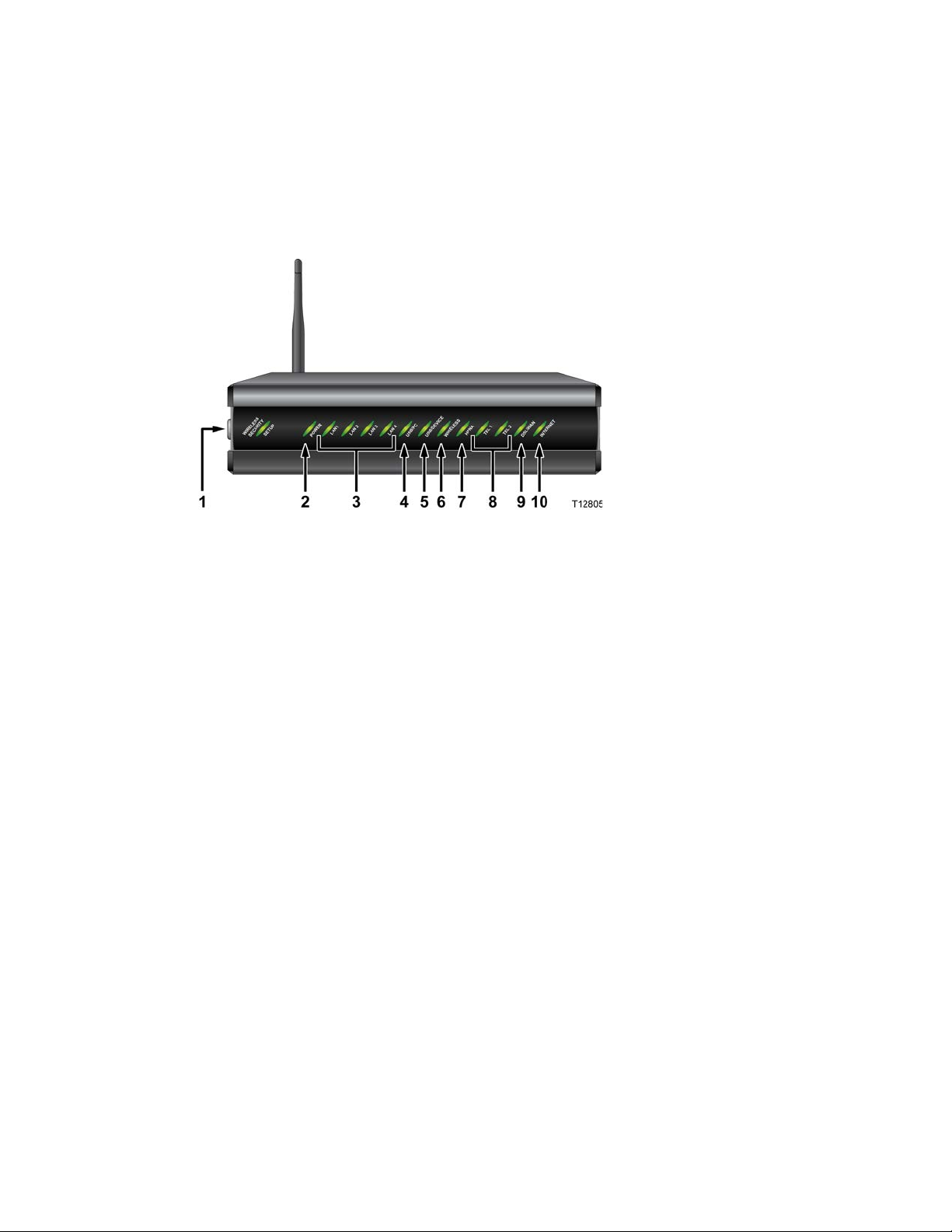
What's On the Front Panel?
The front panel of your residential gateway provides LED status indicators that
indicate the operational state of your gateway. Refer to the following diagram for a
description of the front panel.
1 wifi-sec—Allows you to automatically configure the wireless device in the
home. The WIRELESS SECURITY SETUP LED shows whether automatic
wireless security is on or off
2 POWER—Illuminates solid green to indicate that AC power is being applied to
the residential gateway
3 LAN1 - LAN4—Illuminates solid green to indicate that an Ethernet carrier is
present and blinks to indicate that Ethernet data is being transferred between the
PC and the residential gateway
4 USB/PC—Illuminates solid green to indicate that a USB carrier is present and
blinks to indicate that USB data is being transferred between the PC and the
residential gateway
5 USB/DEVICE—Illuminates solid green to indicate that a USB carrier is present
and blinks to indicate that USB data is being transferred between the connected
USB device and the residential gateway
6 WIRELESS—Illuminates solid green when the wireless access point is enabled
and operational and blinks to indicate that wireless data is being transferred
between the PC and the residential gateway. The LED is off when the wireless
access point is disabled by the user
7 HPNA—Illuminates solid when linked to another HPNA device and blinks
when HPNA activity occurs
8 TEL 1 and TEL 2—TEL 1 illuminates solid green when telephony service is in
use. TEL2 illuminates solid green when telephony service is in use.
Page 27

What's On the Front Panel?
4036168 Rev B 5
9 DSL/WAN—Indicates whether a DSL signal is acquired (or trained). The LED
indicators mean the following status:
Off. Not trained.
Blinking. In training.
Solid. Trained.
In addition, once the DSL/WAN LED is solid, if any pair drops, the DSL/WAN
LED will blink differently to provide additional status as follows:
If the outer pair drops, the LED blinks slowly (about 1 blink every second).
When the inner pair drops, the LED blinks faster (about 4 blinks every
second).
10 INTERNET—Indicates wide area network (WAN) traffic. The LED indicators
mean the following status:
Solid. IP is connected.
Blinking. WAN interface has activity.
Off. No Internet connection.
Page 28
Chapter 1 Introducing the DDR2200 Series Residential Gateway
6 4036168 Rev B
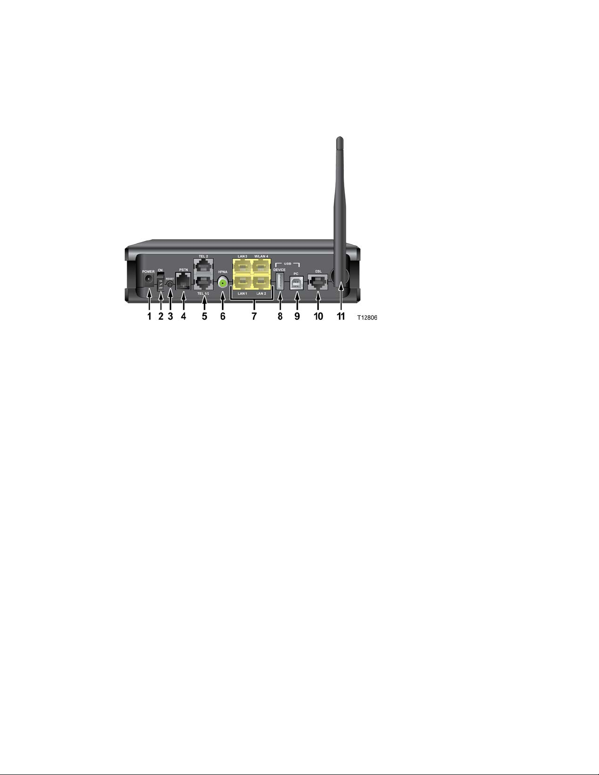
What's On the Back Panel?
Refer to the following diagram for a description of the back panel components.
Important! Do not connect your PC to both the Ethernet and USB ports at the same
time. Your gateway will not function properly if both the Ethernet and USB ports are
connected to your PC at the same time.
1 POWER—Connects the residential gateway to the AC power plug that is
provided with your residential gateway
2 On and Off Switch—Powers the residential gateway on and off
3 RESET—Activating this switch resets the residential gateway. Pressing this
switch for more than 10 seconds resets the device to factory default values and
resets the residential gateway
4 PSTN—Connects to the home telephone wiring and is used as a backup to voice
over IP (VoIP) service in the event of a power outage to the residential gateway
5 TEL 1 and TEL 2—RJ-11 telephone ports connect to home telephone wiring to
conventional telephones or fax machines
6 HPNA—Connects to the coaxial cable wiring in the house for data and video
distribution
7 LAN 1-LAN 3 W/LAN 4—Four RJ-45 Ethernet ports connect as follows:
LAN 1 through 3 connect to the Ethernet port on your PC or your home
network
W/LAN 4 connects to the Ethernet port on your PC if used as a LAN port or
optionally as an Ethernet wide area network (WAN) port that connects to the
service provider network
8 USB DEVICE—12 Mbps USB port connects to the USB port on your device such
as a flash drive or digital camera
Page 29

What's On the Back Panel?
4036168 Rev B 7
9 USB PC—12 Mbps USB port connects to the USB port on your PC
10 DSL—RJ-11 port connects to the DSL line from the service provider
11 ANTENNA—Receives and transmits data packets to wireless devices
Page 30

Page 31

4036168 Rev B 9
2 Chapter 2
Installing the Residential
Gateway
You can install the residential gateway in your home office and access
the Internet from your kitchen computer to get your favorite recipe.
Use this chapter to properly install your residential gateway and to
connect the residential gateway to your computer and other devices in
your home.
In This Chapter
Mounting the Residential Gateway Vertically ................................. 10
Mounting the Residential Gateway to the Wall ............................... 11
Connecting Your Computer to the Residential Gateway................ 12
Connecting the DSL Interface ............................................................. 14
Connecting an IP Set-Top to the Gateway ........................................ 15
Page 32

Chapter 2 Installing the Residential Gateway
10 4036168 Rev B
Mounting the Residential Gateway Vertically
Some installations may require that you place the residential gateway in a vertical
position. Use proper care when installing the residential gateway in a vertical
position. Be sure that the housing of the residential gateway is vertical and that the
stand is extended as shown in the following illustration:
Page 33

Mounting the Residential Gateway to the Wall
4036168 Rev B 11
Mounting the Residential Gateway to the Wall
The following illustration shows the location and dimensions of the wall-mounting
slots on the bottom of the residential gateway. Use the information on this page as a
guide for mounting your residential gateway to the wall.
Page 34

Chapter 2 Installing the Residential Gateway
12 4036168 Rev B
Connecting Your Computer to the Residential Gateway
You can connect a computer to the residential gateway using one of the following
methods:
Ethernet Connection
Wireless Connection
Note: These instructions describe a PC connection. You could also connect another
type of device with a wireless interface. See the owner's manual that came with the
device for instructions.
Connecting the Computer with an Ethernet Connection
Complete these steps to connect the computer with an Ethernet connection.
1 Connect the power adapter that came with the residential gateway to the
POWER port on the residential gateway and to an electrical outlet.
2 Power on the residential gateway. After the residential gateway has completed
its startup process, the POWER LED on the front panel of the residential gateway
should be green.
3 Connect the Ethernet cable provided with the residential gateway from any
available Ethernet port (LAN 1 through LAN 4) on the gateway to the Ethernet
port on the computer.
4 Connect the gray cable provided with the residential gateway from the DSL port
on the gateway to a telephone wall jack. See Connecting the DSL Interface (on
page 14) for more information.
Page 35

Connecting Your Computer to the Residential Gateway
4036168 Rev B 13
Connecting the Computer with a Wireless Connection
A wireless connection requires a wireless-enabled notebook or a computer with an
802.11b/g wireless network adapter installed.
Complete these steps to connect the computer with a wireless connection.
1 Connect the power adapter that came with the residential gateway to the
POWER port on the residential gateway and to an electrical outlet.
2 Power on the residential gateway. After the residential gateway has completed
its startup process, the POWER light on the front panel of the residential
gateway should be green.
3 Connect the gray cable provided with the residential gateway from the DSL port
on the residential gateway to a telephone wall jack. See Connecting the DSL
Interface (on page 14) for more information.
4 Follow the instructions in your owner's manual for your PC or laptop to activate
the wireless connection.
Page 36

Chapter 2 Installing the Residential Gateway
14 4036168 Rev B
Connecting the DSL Interface
Now that you have connected the gateway to power and you have made the LAN
connections, you can connect the DSL interface (connection to the wall jack) as
shown in the following illustration. This illustration shows all of the attached
devices connected to the residential gateway.
Page 37

Connecting an IP Set-Top to th e Gate wa y
4036168 Rev B 15
Connecting an IP Set-Top to the Gateway
For IPTV service, you must connect the residential gateway to an IP set-top. You can
connect to an IP set-top using an Ethernet or coaxial connection.
Ethernet Connection
Complete the following steps to connect the residential gateway to an IP set-top
through Ethernet for IPTV service.
1 Ensure that the residential gateway is powered on.
2 Connect an Ethernet cable from the Ethernet port (LAN 1 through LAN 4) on the
gateway to the Network port on the set-top.
3 Power on the IP set-top.
Page 38

Chapter 2 Installing the Residential Gateway
16 4036168 Rev B
Coaxial Connection
Complete the following steps to connect the residential gateway to an IP set-top with
coaxial cable for IPTV service.
1 Ensure that the residential gateway is powered on.
2 Connect a coaxial cable from the HPNA port on the gateway to the TO WALL
(Video In) port on the set-top.
3 Power on the IP set-top.
Page 39

4036168 Rev B 17
The DDR2200 residential gateway contains web pages that show the
3 Chapter 3
Configuration and Operation
current status of the residential gateway and that allow you to
configure the device. Advanced users can configure parameters such
as DHCP (Dynamic Host Configuration Protocol), wireless network
settings, port forwarding, parental control, and so forth. This section
provides information that you can use to configure and interact with
the residential gateway through the user interface. The screens shown
in this guide represent the default values for the device.
Use this chapter to help you check the status of the residential gateway
and to configure the device.
Page 40

Chapter 3 Configuration and Operation
18 4036168 Rev B
In This Chapter
Logging In to the Residential Gateway ............................................. 19
System Summary .................................................................................. 21
Setting Up Your System with the Setup Wizard .............................. 22
Setting System Date and Time ............................................................ 26
Setting Password ................................................................................... 27
DHCP Leases ......................................................................................... 28
WAN Information ................................................................................. 29
Route Information ................................................................................. 30
ARP Information ................................................................................... 31
CPU Information ................................................................................... 32
Memory Information ............................................................................ 33
LAN Statistics ........................................................................................ 34
WAN Statistics ...................................................................................... 35
ATM Statistics ....................................................................................... 36
Tools - Update Software ...................................................................... 37
Updating Software ................................................................................ 38
Settings Backup ..................................................................................... 40
Update Settings ..................................................................................... 42
Customer Configuration File .............................................................. 44
Restore Default Settings ....................................................................... 46
Saving the Configuration for the Residential Gateway ................... 48
Time Settings ......................................................................................... 50
Service Control ...................................................................................... 53
IP Access Control .................................................................................. 55
Password Access to the Residential Gateway .................................. 58
HTTP Server Port .................................................................................. 61
ALG Settings .......................................................................................... 63
System Log Configuration ................................................................... 65
System Logs ........................................................................................... 71
Print Server Settings ............................................................................. 73
Clone MAC Addresses ......................................................................... 76
Voice SIP Basic Configuration ............................................................ 79
Voice SIP Advanced Configuration ................................................... 84
USB File List ........................................................................................... 88
Page 41

4036168 Rev B 19
Logging In to the Residential Gateway
The default configuration of the residential gateway uses IP address 192.168.1.254. If
you have connected the residential gateway correctly and you have properly
configured your computer, use the following steps to log in to the residential
gateway as an administrator.
Note: A non-administrative user may need a different user name and password for
logging in to the residential gateway. These users can access non-privileged
information.
1 On your PC, open the web browser that you prefer to use.
2 In the address field, enter the following IP address: 192.168.1.254. The system
prompts you to enter your user name and password.
Page 42

Chapter 3 Configuration and Operation
20 4036168 Rev B
3 Enter admin for the user name and admin for the password. The residential
gateway opens with the System Summary page in the forefront.
You can use this web interface to check the status of the residential gateway and
to configure parameters.
Note: The screens shown in this guide represent the default values for the
device.
Page 43

System Summary
4036168 Rev B 21
System Summary
The System Summary screen provides a summary of the software used by the
residential gateway and indicates the current status of the DSL connection. You can
use this screen to find hardware and software information as well as physical and IP
layer information.
This screen also provides a link to the Setup Wizard. The Setup Wizard is a step-bystep sequence to set up your residential gateway for the first time to ensure proper
operation.
The Log Out button on this screen allows you to quickly log out and log back in
without opening a browser.
Path: System > Summary
Page 44

Chapter 3 Configuration and Operation
22 4036168 Rev B
Setting Up Your System with the Setup Wizard
The Setup Wizard is a step-by-step sequence to set up your residential gateway for
the first time to ensure proper operation. The wizard combines the various tasks into
one convenient tool to reduce configuration time. The wizard requires that you make
a few selections within this process. Your selections will depend on your service
provider.
To set up your system with the Setup Wizard, complete the following steps.
1 Click System on the main screen. The System Summary window opens.
2 Click Setup Wizard at the top of the screen. The (Setup Wizard 1/4) ------ Clone
MAC screen opens.
Page 45

Setting Up Your System with the Setup Wizard
4036168 Rev B 23
3 Do you want to enable the clone MAC function? MAC cloning enables you to
change the MAC address of the residential gateway to match the MAC address
of your PC or any service provider supplied MAC address. If you do not enable
MAC cloning, the default MAC address of the residential gateway is used.
If yes, select the Enable clone MAC address check box. A field appears for
you to enter the MAC address you want to clone. Go to step 4.
If no, clear the Enable clone MAC address check box. Go to step 5.
4 In the MAC address field, type in a MAC address or click Load client PCMAC to
load your PC's MAC address.
5 Click Next. The (Setup Wizard 2/4 ------- Time Settings) screen opens. This
screen lets you synchronize the time on the residential gateway with an Internet
time server. If you do not synchronize the time with an Internet time server, the
residential gateway will use its default time.
6 Do you want to automatically synchronize the time on the residential gateway
with an Internet Time server?
If yes, check the Automatically synchronize with Internet time servers check
box. Go to step 7.
If no, clear the Automatically synchronize with Internet time servers check
box. The residential gateway will get its time from its own internal clock. Go
to step 9.
7 In the First NTP time server field, select the Network Time Protocol (NTP) time
server from the drop-down list that you want the residential gateway to check
first to get its time.
Page 46

Chapter 3 Configuration and Operation
24 4036168 Rev B
8 In the Second NTP time server field, select the time server from the drop-down
list that you want to use as a backup server for the residential gateway to get its
time.
9 In the Time zone offset field, select your time zone from the drop-down list.
10 Click Next. The (Setup Wizard 3/4) ------- Wireless Basic Settings screen opens.
The residential gateway offers wireless capability by default. This screen allows
you to configure the wireless settings to work with the devices in your
environment.
11 Do you want to enable wireless?
If yes, check the Enable Wireless check box.
If no, clear the Enable Wireless check box. The wireless capability of the
residential gateway is disabled, and all devices communicating with the
residential gateway will have to be hard wired.
12 Do you want to prevent other wireless devices from communicating over the
wireless network with the residential gateway?
If yes, select the Hide Access Point check box.
If no, clear the Hide Access Point check box. No devices will be locked out
from communicating with the residential gateway over the wireless network.
13 In the SSID field, enter the service set identifier (SSID).
14 In the Channel field, select the channel from the drop-down list to select the
frequency that you will use for wireless communication. Values are auto and
channels 1 through 11.
Page 47

Setting Up Your System with the Setup Wizard
4036168 Rev B 25
15 In the Wireless Mode field, select one of the following modes:
802.11g & 802.11b
802.11g only
802.11b only
16 In the 54g Protection field, select Auto to enable 54g protection or Off to disable
the function. The Auto option will use RTS/CTS to improve 802.11g performance
in mixed 802.11g/802.11b networks. Turning the protection off maximizes
802.11g throughput under most conditions.
17 Click Next. The (Setup Wizard 4/4) ----- Wireless Security Settings screen opens.
18 In the Select SSID field, select the SSID from the drop-down list that you want to
use.
19 In the Network Authentication field, select one of the following authentication
methods from the drop-down list:
Open. All devices may access the wireless network (preferred option).
Shared. Only devices configured with the 64-bit or 128-bit Key may access
the wireless network.
WPA-PSK (Wi-Fi Protected Access Pre-Shared Key). Your network is secured
by encryption of all traffic using a pre-shared dynamic key.
20 Do you want to enable WEP Encryption?
If yes, in the WEP Encryption field, select Enabled from the drop-down list.
If no, in the WEP Encryption field, select Disabled from the drop-down list.
21 Click Save/Reboot to save the changes you made. You must reboot the gateway
for the changes to take effect.
Page 48

Chapter 3 Configuration and Operation
26 4036168 Rev B
Setting System Date and Time
When you first set up your system with the wizard, you set your system's date and
time. At a later time, you may need to reset the date and time, and you can use the
following procedure.
To set the system date and time, complete the following steps.
1 Click System on the main screen. The System Summary window opens.
2 Under the Admin section on the screen, click NTP Server Setting. The Time
Settings screen opens.
3 Make sure the Automatically synchronize with Internet time servers check box is
checked.
4 In the First NTP time server field, select clock.fmt.he.net from the drop-down
list.
5 In the Second NTP time server field, select time.nist.gov from the drop-down
list.
6 In the Time zone offset field, select the time zone that you want to use from the
drop-down list.
7 Click Save/Apply to save your settings.
Page 49

Setting Password
4036168 Rev B 27
Setting Password
To set the password for the residential gateway, complete the following steps.
1 Click System on the main screen. The System Summary window opens.
2 Under the Admin section on the screen, click Password Setting. The Access
Control -- Password screen opens.
3 In the Username field, select one of the following options for the user name:
admin. Allows unrestricted access to change and view the configuration of
the residential gateway. This login allows access to privileged information.
The default password for this user name is admin.
support. Allows an ISP technician to access your residential gateway for
maintenance and to run diagnostics. The default password for this user name
is support.
user. Allows access to view configuration settings and statistics, as well as, to
update the residential gateway's software. The default password is user.
4 In the Old Password field, enter the old password you have been using.
5 In the New Password field, enter the new password.
6 In the Confirm Password field, enter the new password again to confirm it.
7 Click Save/Apply to save your user name and password.
Page 50

Chapter 3 Configuration and Operation
28 4036168 Rev B
DHCP Leases
The DHCP Leases screen displays the Dynamic Host Configuration Protocol (DHCP)
table. This screen shows a mapping of hosts (shown by their MAC addresses) and
their assigned IP addresses. The DHCP server for the residential gateway assigns
these IP addresses to the devices. The screen also shows when the lease for the IP
address expires.
Path: System > Details > LAN DHCP
Page 51

WAN Information
4036168 Rev B 29
WAN Information
The WAN Info screen provides information about the ADSL2+ wide area network
(WAN) parameters and status. You can use this screen to check the ADSL2+
connection.
Path: System > Details > WAN
In MER protocol (as shown here), press Release or Renew to release your current
WAN IP address and obtain a new DHCP lease. In PPPoE or PPPoA protocol, press
Connect to activate a new WAN connection, or press Disconnect to disable the
connection as shown in the following illustration.
Page 52

Chapter 3 Configuration and Operation
30 4036168 Rev B
Route Information
The Route Info screen shows the routing table for the residential gateway. This
screen provides the gateway address for specific destination IP addresses.
Path: System > Details > Route
Page 53

ARP Information
4036168 Rev B 31
ARP Information
The ARP Info screen displays the Address Resolution Protocol (ARP) table. This
table shows the IP address to MAC address mapping.
Path: System > Details > ARP
Page 54

Chapter 3 Configuration and Operation
32 4036168 Rev B
CPU Information
The CPU Info screen shows detailed information about the CPU utilization and the
active processes running on the residential gateway.
Path: System > Details > CPU Info
Page 55

Memory Information
4036168 Rev B 33
Memory Information
The Memory Info screen shows the detailed memory availability of the residential
gateway.
Path: System > Details > Memory Info
Page 56

Chapter 3 Configuration and Operation
34 4036168 Rev B
LAN Statistics
The Statistics -- LAN screen displays statistics for the local area network (LAN). This
screen shows the number of transmitted and received packets on the LAN interface
for Ethernet, USB, and wireless devices.
Path: System > Statistics > LAN
Reset Statistics
To reset the statistics, click Reset Statistics on the screen. This action clears the
counters and sets them to zero for the packets received and transmitted on the LAN
interface.
Page 57

WAN Statistics
4036168 Rev B 35
WAN Statistics
The Statistics -- WAN screen displays statistics for the devices and interfaces on the
wide area network (WAN). This screen shows the number of transmitted and
received packets for the DSL WAN interface.
Path: System > Statistics > WAN
Reset Statistics
To reset the statistics, click Reset Statistics on the screen. This action clears the
counters and sets them to zero for the packets received and transmitted on the WAN
interface.
Page 58

Chapter 3 Configuration and Operation
36 4036168 Rev B
ATM Statistics
The Statistics -- ATM screen displays statistics on the ATM interface. This screen
shows the ATM Layer-2 statistics such as the number of ATM cells transmitted and
received over the ATM interface.
Path: System > Statistics > ATM
Reset Statistics
To reset the statistics, click Reset on the screen. This action clears the counters and
sets them to zero for the packets received and transmitted on the ATM interface.
Page 59

Tools - Update Software
4036168 Rev B 37
Tools - Update Software
The Tools -- Update Software screen allows you to update the software for the
residential gateway with a new version.
Path: System > Management > Configuration > Update Software
Page 60

Chapter 3 Configuration and Operation
38 4036168 Rev B
Updating Software
To update the software for the residential gateway, complete the following steps.
1 Click System on the main screen.
2 Click Management. The Configuration screen opens with the Configuration tab
in the forefront.
3 Click Update Software. The Tools Update Software screen opens.
Note: This screen also gives you the option of uploading the bonding master
image or the dual image (master and slave firmware together).
4 In the Software File Name field, click Browse to locate the software image file.
Then:
To restore the residential gateway to factory defaults following the update,
check the Restore to default settings after update software image option.
To retain the current residential configuration following the update, leave
this option unchecked.
Page 61

Updating Software
4036168 Rev B 39
5 Click Update Software to update the software of your residential gateway with
the new version. The residential gateway loads the new software and reboots
when the software update is complete.
Page 62

Chapter 3 Configuration and Operation
40 4036168 Rev B
Settings Backup
The Settings - Backup screen allows you to back up the residential gateway
configuration and save it to disk.
Path: System > Management > Configuration > Back Up Config File
Backing Up Configuration Settings
To back up the configuration settings for the residential gateway, complete the
following steps.
1 Click System on the main screen.
2 Click Management. The Configuration screen opens with the Configuration tab
in the forefront.
Page 63

Settings Backup
4036168 Rev B 41
3 Click Backup Config file. The Settings - Backup screen opens.
4 Click Back Up Settings. The following screen is displayed.
5 Click Save. The system prompts you to select a location to store the backup.
6 Select a location and type in a file name.
7 Click Save to save a backup of the configuration. The system displays a message
when the download of the file is complete.
Page 64

Chapter 3 Configuration and Operation
42 4036168 Rev B
Update Settings
The Update Settings screen allows you to update the settings for the residential
gateway from a source file. We recommend that you use this feature if you want to
set up multiple residential gateways with a similar configuration.
Path: System > Management > Configuration > Update Config File
Updating Configuration Settings
To update the configuration settings for the residential gateway, complete the
following steps.
1 Click System on the main screen.
2 Click Management. The Configuration screen opens with the Configuration tab
in the forefront.
Page 65

Update Settings
4036168 Rev B 43
3 Click Update Config file. The Update Settings screen opens.
4 In the Settings File Name field, enter the name of the configuration file that you
want to use to update your settings. You can click Browse to locate the file.
5 Click Update Settings to update the configuration of the residential gateway.
6 Wait a few minutes while the system reboots the residential gateway. The new
configuration takes effect after the residential gateway reboots.
Page 66

Chapter 3 Configuration and Operation
44 4036168 Rev B
Customer Configuration File
This feature lets you create your own "factory default" configuration so that, when a
user presses the Reset button or performs Restore Default Settings from the web UI,
the user's device resets to your default settings rather than to the device's original
factory default configuration.
You can use this feature to upload your customized configuration file and make this
your own factory default configuration. You also have the option to delete the file.
Note: If you need to revert to the factory default settings, you can press the Restore
Default Settings button on the screen or the Reset button on the device. For more
information, see Restore Default Settings (on page 46).
Path: System > Management > Configuration > Update Config File
1 Click System on the main screen.
2 Click Management. The Configuration screen opens with the Configuration tab
in the forefront.
3 Click Customer Config file. The Customer Settings screen opens.
4 Click Browse to select the configuration file that you have previously saved.
5 Click Upload to upload your configuration file. You may also delete your
uploaded configuration file by pressing the Erase button on the screen.
Page 67

Customer Configuration File
4036168 Rev B 45
Notes:
When you delete your uploaded customer config file by clicking Erase, the
system reverts to the device's original factory default settings.
If the uploaded customer config file exists, the system will reset to the new
settings when you click Restore Default Settings in the web UI or press the
Reset button on the device.
Page 68

Chapter 3 Configuration and Operation
46 4036168 Rev B
Restore Default Settings
The Restore Default Settings screen allows you to restore the residential gateway
configuration to the default settings.
Note: You can also reset the device by inserting a sharp instrument, such as a paper
clip, in the reset area on the back of the residential gateway.
Path: System > Management > Configuration > Restore Default Settings
Restoring the Configuration to the Default Settings
To restore the configuration to the default settings, complete the following steps.
1 Click System on the main screen.
2 Click Management. The Configuration screen opens with the Configuration tab
in the forefront.
Page 69

Restore Default Settings
4036168 Rev B 47
3 Click Restore Default Settings. The Tools Restore Default Settings screen opens.
4 Click Restore Default Settings. The system displays the following prompt:
5 Click OK. The system displays the following message:
6 Follow the on-screen instructions to restore the default settings.
Page 70

Chapter 3 Configuration and Operation
48 4036168 Rev B
Saving the Configuration for the Residential Gateway
The Reboot the Residential Gateway screen allows you to save any configuration
changes and to reboot the router to make the changes take effect.
Path: System > Management > Configuration > Restore Default Settings >
Save/Reboot
Saving the Configuration and Rebooting the Residential Gateway
To save any configuration changes and to reboot the router to make the changes take
effect, complete the following steps.
1 Click System on the main screen.
2 Click Management. The Configuration screen opens with the Configuration tab
in the forefront.
Page 71

Saving the Configuration for the Residential Gateway
4036168 Rev B 49
3 Click Save/Reboot. The system displays the following message:
4 Follow the instructions on the screen to save the configuration and to reboot the
router. The residential gateway displays the following message shown below.
The System Summary screen opens when the residential gateway has finished
rebooting. The new settings are displayed.
Page 72

Chapter 3 Configuration and Operation
50 4036168 Rev B
Time Settings
The Time Settings screen allows you to synchronize the time for the residential
gateway with a network-based time server.
Path: System > Management > Settings > Internet Time
Synchronize with Internet Time
To synchronize the time for the residential gateway with the Internet time, complete
the following steps.
1 Click System on the main screen.
2 Click Management. The Configuration screen opens with the Configuration tab
in the forefront.
Page 73

Time Settings
4036168 Rev B 51
3 Click the Settings tab. The Settings screen opens.
4 Click Internet Time. The Time Settings screen opens.
5 Check the box Automatically synchronize with Internet time servers. The Time
Settings screen opens with populated fields.
6 In the First NTP time server field, select a time server from the drop-down list. If
you select Other, enter the name of the server in the blank field.
Page 74

Chapter 3 Configuration and Operation
52 4036168 Rev B
7 In the Second NTP time server field, select a time server from the drop-down list.
If you select Other, enter the name of the server in the blank field.
8 In the Time zone offset field, select the time zone specific to your area.
9 Click Save/Apply.
Page 75

Service Control
4036168 Rev B 53
Service Control
The Service Control screen allows you to enable or disable services such as FTP,
HTTP, and ICMP on the residential gateway.
Path: System > Management > Settings > Service Control List
Enabling or Disabling Services
To enable or disable services on the residential gateway, complete the following
steps.
1 Click System on the main screen.
2 Click Management. The Configuration screen opens with the Configuration tab
in the forefront.
Page 76

Chapter 3 Configuration and Operation
54 4036168 Rev B
3 Click the Settings tab. The Settings screen opens.
4 Click Service Control List. The Service Control screen opens.
5 To enable or disable a service, do the following:
To enable a service, select the check box next to the service you want to
enable. A check box with a check indicates that the service is enabled.
To disable a service, de-select the check box next to the service you want to
disable. A check box without a check indicates that the service is disabled.
6 Click Save/Apply to enable or disable the selected services.
Page 77

IP Access Control
4036168 Rev B 55
IP Access Control
The IP Address Access Control mode, if enabled, permits access to local
management services from IP addresses contained in the Access Control List. If the
Access Control mode is disabled, you cannot configure the residential gateway from
non-local IP addresses. For example, you can use this feature to prevent a remote site
from configuring the residential gateway. The services are the system applications
listed in the Service Control List.
Path: System > Management > Settings > IP Access Control
Page 78

Chapter 3 Configuration and Operation
56 4036168 Rev B
Adding IP Address Access Control
To add IP address access control, complete the following steps.
1 Click System on the main screen. The System Summary screen opens by default.
2 Click Management. The Configuration screen opens with the Configuration tab
in the forefront.
3 Click the Settings tab. The Settings screen opens.
4 Click IP Access Control. The Access Control -- IP Address screen opens.
Page 79

IP Access Control
4036168 Rev B 57
5 Click Add. The Access Control screen opens. In the IP Address field, enter the IP
address of the management station that you want to allow access to the local
management services.
6 In the IP Address field, enter the IP address of the management station that you
want to allow access to the local management services.
7 Click Save/Apply to allow access for the IP address you entered.
8 Enable the Access Control Mode as shown in the following screen.
Page 80

Chapter 3 Configuration and Operation
58 4036168 Rev B
Password Access to the Residential Gateway
Access to the residential gateway is controlled through three user accounts:
admin. Allows unrestricted access to change and view the configuration of the
residential gateway. This login allows access to privileged information.
support. Allows an ISP technician to access your residential gateway for
maintenance and to run diagnostics
user. Allows access to view configuration settings and statistics, as well as, to
update the residential gateway's software.
The admin login provides access to all screens (including privileged information) for
the residential gateway. The support login and user login provide access to only a
subset of the screens provided to the admin login.
Path: System > Management > Settings > Passwords
Page 81

Password Access to the Residential Gateway
4036168 Rev B 59
Creating Password s
To create passwords for the residential gateway, complete the following steps.
1 Click System on the main screen.
2 Click Management. The Configuration screen opens with the Configuration tab
in the forefront.
3 Click the Settings tab. The Settings screen opens.
Page 82

Chapter 3 Configuration and Operation
60 4036168 Rev B
4 Click Passwords. The Access Control -- Passwords screen opens.
5 In the Username field from the drop-down list, select the type of password you
are creating: admin, support, or user. The default user name is admin.
6 In the Old Password field, enter the old password. The maximum character
length is 16 characters, and passwords cannot contain a space. The default
password is admin.
7 In the New Password field, enter the new password. The maximum character
length is 16 characters, and passwords cannot contain a space.
8 In the Confirm Password field, enter the new password again to confirm your
entry.
9 Click Save/Apply to save the password.
Tip: Another quick way to change passwords is to go to the System (home) page.
Scroll down to the last option and click Password Setting. A popup screen opens
as shown below. Use this screen to enter your new passwords.
Page 83

HTTP Server Port
4036168 Rev B 61
HTTP Server Port
The HTTP Server Port screen allows you to specify the TCP port for the HTTP server
on both the LAN and WAN interfaces.
Path: System > Management > Settings > HttpServer
Modifying the Http Server Ports
To modify the Http Server ports, complete the following steps.
1 Click System on the main screen.
2 Click Management. The Configuration screen opens with the Configuration tab
in the forefront.
Page 84

Chapter 3 Configuration and Operation
62 4036168 Rev B
3 Click the Settings tab. The Settings screen opens.
4 Click HttpServer. The Http Server Port opens.
5 In the LAN Http Server Port field, enter the port number for the HTTP server
from the LAN side.
6 In WAN Http Server Port field, enter the port number for the HTTP server from
the WAN side.
Page 85

ALG Settings
4036168 Rev B 63
ALG Settings
The ALG settings allow you to enable or disable the SIP ALG based on the
customer's requirement.
Path: System > Management > Settings > ALG Settings
Modifying the ALG Settings
To modify the ALG settings, complete the following steps.
1 Click System on the main screen.
2 Click Management. The Configuration screen opens with the Configuration tab
in the forefront.
Page 86

Chapter 3 Configuration and Operation
64 4036168 Rev B
3 Click the Settings tab. The Settings screen opens.
4 Click the last option, ALG Settings. The ALG Settings page opens.
5 Set or clear the SIP Enabled check box, depending on your customer's
requirement.
Page 87

System Log Configuration
4036168 Rev B 65
System Log Configuration
The System Log -- Configuration screen allows you to log all the selected events on
the residential gateway. For example, a failed login is an event that you can select.
Path: System > Management > Local Management > System Log Configuration
Logging Events
To log selected events, complete the following steps.
1 Click System on the main screen.
2 Click Management. The Configuration screen opens with the Configuration tab
in the forefront.
Page 88

Chapter 3 Configuration and Operation
66 4036168 Rev B
3 Click the Local Management tab. The Local Management screen opens.
4 Click System Log Configuration. The System Log Configuration screen opens.
5 Do you want to enable the logging of events?
If yes, in the Log field select Enable and go to step 6.
If no, in the Log field, select Disable and click Save/Apply to turn off
logging. You have completed this procedure.
Page 89

System Log Configuration
4036168 Rev B 67
6 In the Log Level field, select the level of events that you want to log from the
following options. All events above or equal to the selected level will be logged.
Emergency
Alert
Critical
Error
Warning
Notice
Informational
Debugging
7 In the Display Level field, select the level of the logged events that you want to
display from the following options. All logged events above or equal to the
selected level will be displayed.
Emergency
Alert
Critical
Error
Warning
Notice
Informational
Debugging
8 Select the mode for the logging from the following options. If the selected mode
is "remote" or "both," events are sent to the specified IP address and UDP port of
the remote syslog server. If the selected mode is "local" or "both," events are
recorded in the local memory.
Local. Events are logged in memory. You must log in to the device to display
the events.
Remote. Events log is sent to a remote server (syslog server).
Both. Events are logged in memory and are sent to the remote server.
9 Click Save/Apply to start logging events.
Page 90

Chapter 3 Configuration and Operation
68 4036168 Rev B
Disabling Logging
To disable the logging function, complete the following steps.
1 Click System on the main screen.
2 Click Management. The Configuration screen opens with the Configuration tab
in the forefront.
3 Click the Local Management tab. The Local Management screen opens.
Page 91

System Log Configuration
4036168 Rev B 69
4 Click System Log Configuration. The System Log Configuration screen opens.
5 In the Log field, click Disable.
6 In the Log Level field, select from the following options to indicate the level of
alarms to be logged:
Emergency
Alert
Optical
Error
Warning
Notice
Informational
Debugging
7 In the Display Level field, select from the following options to indicate the level
of alarms that you want displayed:
Emergency
Alert
Optical
Error
Warning
Notice
Informational
Debugging
Page 92

Chapter 3 Configuration and Operation
70 4036168 Rev B
8 In the Mode field, select from the following options to indicate the location to
store the logs.
Local. Store on the residential gateway.
Remote. Store on a remote log server.
Both. Store on the residential gateway and on the remote log server.
9 Click Save/Apply. The following prompt appears alerting you that you will lose
any information captured by the residential gateway:
10 Are you sure you want to disable logging and lose the captured data?
If yes, click OK to turn off logging.
If no, click Cancel.
Page 93

System Logs
4036168 Rev B 71
System Logs
The System Log screen allows you to view the logs of activity for the residential
gateway.
Path: System > Management > Local Management > View System Log
Viewing System Logs
To view the system log for the residential gateway, complete the following steps.
1 Click System on the main screen.
2 Click Management. The Configuration screen opens with the Configuration tab
in the forefront.
Page 94

Chapter 3 Configuration and Operation
72 4036168 Rev B
3 Click the Local Management tab. The Local Management screen opens.
4 Click View System Log. The System Log screen opens.
5 Review the log entries on the screen.
6 Click Refresh to refresh the system log.
Page 95

Print Server Settings
4036168 Rev B 73
Print Server Settings
The Print Server Setting screen allows you to enable or disable printer support from
the USB connection.
Path: System > Advanced > Print Server
Enabling the Print Server
To enable the print server, complete the following steps.
1 Click System on the main screen.
2 Click the Advanced tab. The Print Server settings screen opens with the Print
Server tab in the forefront.
Page 96

Chapter 3 Configuration and Operation
74 4036168 Rev B
3 Check the Enable on-board print server check box. The screen populates with
more fields.
4 In the Print server name field, enter the name of the print server you want to
enable.
5 In the Make and model field, enter the make and model of the printer.
6 Click Save/Apply to enable the print server.
Disabling the Print Server
To disable the print server, complete the following steps.
1 Click System on the main screen.
2 Click the Advanced tab. The Print Server settings screen opens with the Print
Server tab in the forefront.
Page 97

Print Server Settings
4036168 Rev B 75
3 Clear the Enable on-board print server check box. The screen refreshes and the
fields for entering print server name, make, and mode are removed from the
screen.
4 Click Save/Apply to disable the print server.
Page 98

Chapter 3 Configuration and Operation
76 4036168 Rev B
Clone MAC Addresses
The Clone MAC screen allows you to enable or disable the clone MAC function. The
Clone MAC function allows you to clone MAC addresses so that the residential
gateway assumes the MAC address of an attached device or a user-specified MAC
address.
Path: System > Advanced > Clone MAC
Enabling the Clone MAC Function
To enable the Clone MAC function, complete the following steps.
1 Click System on the main screen.
2 Click the Advanced tab. The Print Server settings screen opens with the Print
Server tab in the forefront.
Page 99

Clone MAC Addresses
4036168 Rev B 77
3 Click the Clone MAC tab.
4 Select the Enable clone MAC address check box. The screen populates with
more fields.
5 In the MAC Address field, enter the MAC address that you want to clone. You
can also click Load client PC MAC to locate an address you want to clone.
6 Click Apply/Reboot to clone the MAC address. The residential gateway reboots
and assumes the MAC address you have specified.
Page 100

Chapter 3 Configuration and Operation
78 4036168 Rev B
Disabling the Clone MAC Function
To disable the Clone MAC function, complete the following steps.
1 Click System on the main screen.
2 Click the Advanced tab. The Print Server settings screen opens with the Print
Server tab in the forefront.
3 Click the Clone MAC tab.
4 Uncheck the Enable clone MAC address check box. The screen refreshes and the
field for entering the MAC address is removed from the screen.
5 Click Apply/Reboot to disable the Clone MAC function.
 Loading...