

Page 1

78-4043743-01 Rev A
Cisco D9887B HDTV Modular
Receiver Software Version 7.7
Installation and Configuration Guide
Page 2

Notices
Trademark Acknowledgments
Cisco and the Cisco logo are trademarks or registered trademarks of Cisco and/or its
affiliates in the U.S. and other countries. To view a list of Cisco trademarks, go to this
URL: www.cisco.com/go/trademarks.
Manufactured under license from Dolby Laboratories. Dolby and the double-D
symbol are trademarks of Dolby Laboratories.
The DVB logo is a registered trademark of the DVB Project.
Other third party trademarks mentioned are the property of their respective owners.
The use of the word partner does not imply a partnership relationship between
Cisco and any other company. (1110R)
Publication Disclaimer
Cisco Systems, Inc. assumes no responsibility for errors or omissions that may
appear in this publication. We reserve the right to change this publication at any
time without notice. This document is not to be construed as conferring by
implication, estoppel, or otherwise any license or right under any copyright or
patent, whether or not the use of any information in this document employs an
invention claimed in any existing or later issued patent.
Copyright
© 2009-2013 Cisco and/or its affiliates. All rights reserved. Printed in the United States of
America.
Information in this publication is subject to change without notice. No part of this
publication may be reproduced or transmitted in any form, by photocopy,
microfilm, xerography, or any other means, or incorporated into any information
retrieval system, electronic or mechanical, for any purpose, without the express
permission of Cisco Systems, Inc.
Page 3

Please Read This Entire Guide
Veuillez lire entièrement ce guide
Bitte das gesamte Handbuch durchlesen
Sírvase leer completamente la presente guía
Si prega di leggere completamente questa guida
Important
Please read this entire guide before you install or operate this product. Give
particular attention to all safety statements.
Important
Veuillez lire entièrement ce guide avant d'installer ou d'utiliser ce produit. Prêtez
une attention particulière à toutes les règles de sécurité.
Zu beachten
Bitte lesen Sie vor Aufstellen oder Inbetriebnahme des Gerätes dieses Handbuch in
seiner Gesamtheit durch. Achten Sie dabei besonders auf die Sicherheitshinweise.
Importante
Sírvase leer la presente guía antes de instalar o emplear este producto. Preste
especial atención a todos los avisos de seguridad.
Importante
Prima di installare o usare questo prodotto si prega di leggere completamente questa
guida, facendo particolare attenzione a tutte le dichiarazioni di sicurezza.
Page 4

Page 5
Safety Precautions
78-4043743-01 Rev A v
Safety Precautions
1 Read these instructions.
2 Keep these instructions.
3 Heed all warnings.
4 Follow all instructions.
5 Do not use this apparatus near water.
6 Clean only with dry cloth.
7 Do not block any ventilation openings. Install in accordance with the
manufacturer's instructions.
8 Do not install near any heat sources such as radiators, heat registers, stoves, or
other apparatus (including amplifiers) that produce heat.
9 Do not defeat the safety purpose of the polarized or grounding-type plug. A
polarized plug has two blades with one wider than the other. A grounding type
plug has two blades and a third grounding prong. The wide blade or the third
prong is provided for your safety. If the provided plug does not fit into your
outlet, consult an electrician for replacement of the obsolete outlet.
10 Protect the power cord from being walked on or pinched particularly at plugs,
convenience receptacles, and the point where they exit from the apparatus.
Page 6

Safety Precautions
vi 78-4043743-01 Rev A
11 Only use attachments/accessories specified by the manufacturer.
12 Use only with the cart, stand, tripod, bracket, or table specified by the
manufacturer, or sold with the apparatus. When a cart is used, use caution when
moving the cart/apparatus combination to avoid injury from tip-over.
13 Unplug this apparatus during lightning storms or when unused for long periods
of time.
14 Refer all servicing to qualified service personnel. Servicing is required when the
apparatus has been damaged in any way, such as power-supply cord or plug is
damaged, liquid has been spilled or objects have fallen into the apparatus, the
apparatus has been exposed to rain or moisture, does not operate normally, or
has been dropped.
15 Do not expose this apparatus to dripping or splashing and ensure that no objects
filled with liquids, such as vases, are placed on the apparatus.
16 To completely disconnect this apparatus from the AC Mains, disconnect the
power supply cord plug from the AC receptacle.
17 The mains plug of the power supply cord shall remain readily operable.
18 Damage Requiring Service: Unplug this product from the wall outlet and refer
servicing to qualified service personnel under the following conditions:
a When the power-supply cord or plug is damaged.If liquid has been spilled,
or objects have fallen into the product.
b If the product has been exposed to rain or water.
c If the product does not operate normally by following the operating
instructions. Adjust only those controls that are covered by the operating
instructions as an improper adjustment of the controls may result in damage
and will often require extensive work by a qualified technician to restore the
product to its normal operation.
d If the product has been dropped or damaged in any way.
e The product exhibits a distinct change in performance.
19 Replacement Parts: When replacement parts are required, be sure the service
technician uses replacement parts specified by Cisco, or parts having the same
operating characteristics as the original parts. Unauthorized part substitutions
made may result in fire, electric shock or other hazards.
Page 7
Safety Precautions
78-4043743-01 Rev A vii
20 Safety Check: Upon completion of any service or repairs made to this product,
ask the service technician to perform safety checks to determine that the product
is in safe operating condition.
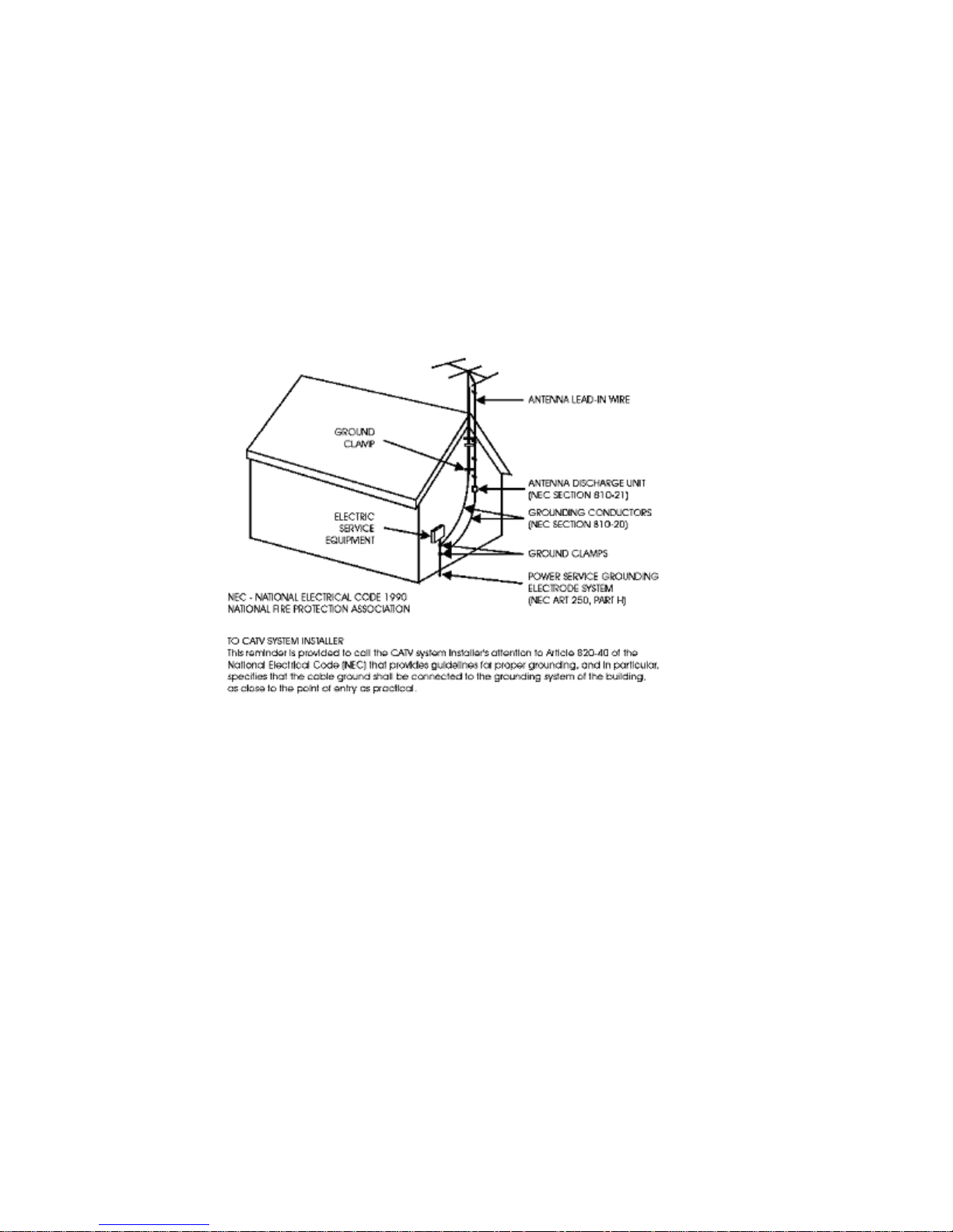
21 Outdoor Antenna Grounding: If an outside antenna or cable system is
connected to this product, ensure that the antenna or cable system is properly
grounded to provide protection against voltage surges and built-up static
charges. Appropriate sections of the National Electrical Code (NFPA 1990)
provide information with respect to proper grounding of the mast and
supporting structure, grounding of the lead-in wire to an antenna discharge unit,
connection to grounding electrodes, and requirements for the grounding
electrode.
Page 8

Safety Precautions
viii 78-4043743-01 Rev A
Safety Precautions
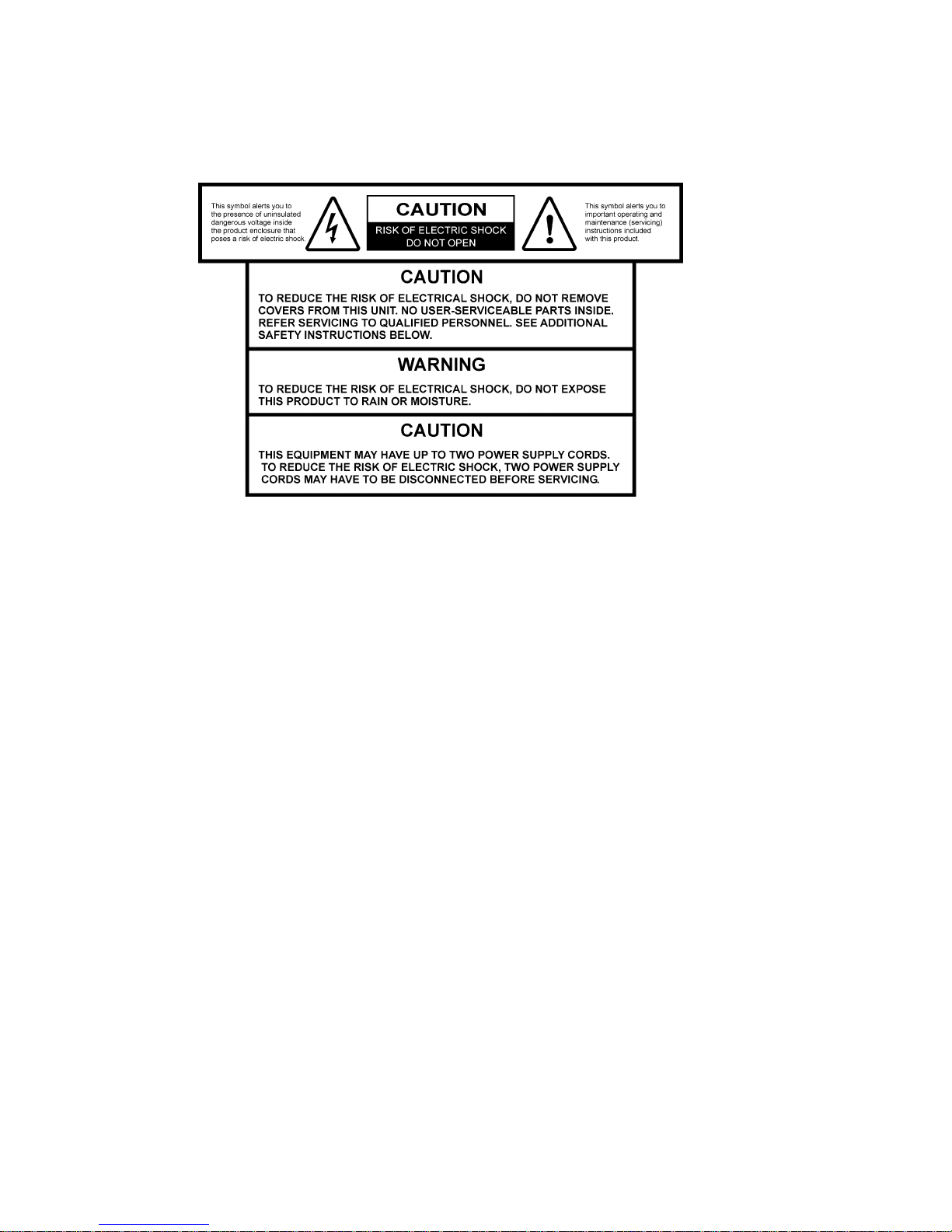
Protect yourself from electric shock and your system from damage!
This product complies with international safety and design standards. Observe
all safety procedures that appear throughout this guide, and the safety symbols
that are affixed to this product.
If circumstances impair the safe operation of this product, stop operation and
secure this product against further operation.
Avoid personal injury and product damage! Do not proceed beyond any symbol
until you fully understand the indicated conditions!
You will find this symbol on the product and/or in the literature that
accompanies this product.
It indicates important operating or maintenance instructions.
You may find this symbol on the product and/or in the literature that
accompanies this product.
It indicates a live terminal; the symbol pointing to the terminal device.
You may find this symbol on the product and/or in the literature that
accompanies this product.
It indicates a protective earth terminal.
You may find this symbol on the product and/or in the literature that
accompanies this product.
It indicates excessive or dangerous heat.
Power
Important! This is a Class I product. You must earth this product.
This product plugs into a socket-outlet. The socket-outlet must be near this product,
and must be easily accessible. Connect this product only to the power source that is
indicated on the back panel of this product. If this product does not have a mains
power switch, the power cord serves this purpose.
Enclosure
Do not allow moisture to enter this product. Do not open the enclosure of this
product unless otherwise specified. Do not push objects through openings in the
enclosure of this product.
Cables
Always pull on the plug or the connector to disconnect a cable. Never pull on the
cable itself. Do not walk on or place stress on cables or plugs.
Page 9

Safety Precautions
78-4043743-01 Rev A ix
Factory service
Refer service only to service personnel who are authorized by the factory.
Règles de sécurité
Protégez-vous des risques d'électrocution et protégez votre système contre les
endommagements éventuels.
Ce produit respecte les standards internationaux de sécurité et de conception.
Veuillez observer toutes les procédures de sécurité qui apparaissent dans ce
guide, ainsi que les symboles de sécurité qui figurent sur le produit.
Si, du fait des circonstances, ce produit cesse de fonctionner normalement, cessez
de l'utiliser et empêchez-en l'utilisation future.
Évitez le risque de blessures et de dommages aux produits! Ne procédez à aucune
tâche tant que vous n'aurez pas entièrement assimilé les conditions indiquées par un
symbole!
Ce symbole figure dans la documentation accompagnant ce produit. Il indique
d'importantes instructions de fonctionnement ou d'entretien.
Ce symbole peut être attaché à ce produit. Il indique une borne sous tension;
la direction indique la borne.
Ce symbole peut être attaché à ce produit. Il indique une borne de terre de
protection.
Ce symbole peut être attaché à ce produit. Il indique une température
excessive ou dangereuse.
Alimentation
Important! Ce produit fait partie de la classe I. Vous devez le mettre à la terre.
Ce produit se branche dans une prise murale. Cette dernière doit être placée à
proximité du produit et doit être facilement accessible.
Ne branchez ce produit qu'à la source d'alimentation indiquée sur son panneau
arrière.
Si ce produit n'a pas d'interrupteur d'alimentation générale, le cordon d'alimentation
remplit ce rôle.
Enceinte
Ne laissez pas l'humidité pénétrer dans ce produit.
N'ouvrez pas l'enceinte de ce produit, sauf instructions contraires.
Ne forcez pas d'objets dans les ouvertures du boîtier.
Page 10

Safety Precautions
x 78-4043743-01 Rev A
Câbles
Tirez toujours sur la prise ou le connecteur pour débrancher un câble, Ne tirez
jamais directement sur le câble.
Ne marchez pas sur les câbles ou les prises et n'y exercez aucune pression.
Réparations effectuées à l'usine
Ne confiez les travaux de réparations qu'au personnel autorisé par l'usine.
Sicherheitsvorkehrungen
Schützen Sie sich gegen elektrischen Schlag, und Ihr Gerät gegen Beschädigung!
Dieses Gerät entspricht internationalen Sicherheits-und Ausführungsnormen.
Beachten Sie alle in diesem Handbuch enthaltenen Sicherheitshinweise sowie die
am Gerät angebrachten Warnzeichen.
Sollten örtliche Umstände den sicheren Betrieb dieses Gerätes beeinträchtigen,
schalten Sie es ab und sichern es gegen weitere Benutzung.
Vermeiden Sie Verletzungen sowie Beschädigung des Gerätes! Wenn Sie zu einem
der folgenden Warnzeichen gelangen, nicht weiterarbeiten, bis Sie seine Bedeutung
voll verstanden haben!
Dieses Symbol erscheint auf dem Gerät und/oder in der ihm beiliegenden
Literatur. Es bedeutet wichtige, zu beachtende Betriebs-oder
Wartungsanweisungen.
Wenn dieses Zeichen am Gerät angebracht ist, warnt es vor einer
spannungsführenden Stelle.
Dieses Symbol kennzeichnet auf dem Gerät die Anschlußstelle der
Sicherheitserde.
Wenn dieses Zeichen am Gerät angebracht ist, warnt es vor heißen Stellen, die
zu Verbrennungen führen können.
Netzspannung
Wichtig! Dieses Gerät ist ein Produkt der Schutzklasse I. Es muß geerdet werden.
Das Gerät ist an einer Steckdose anzuschließen. Diese muß sich leicht zugänglich
in unmittelbarer Nähe des Gerätes befinden.
Die Netzversorgung muß den auf der Rückwand des Gerätes angegebenen
Werten entsprechen.
Falls sich kein Hauptschalter am Gerät befindet, dient das Netzkabel diesem
Zweck.
Page 11

Safety Precautions
78-4043743-01 Rev A xi
Gehäuse
Das Innere des Gerätes ist vor Feuchtigkeit zu schützen.
Das Gehäuse ist nicht zu öffnen.
Niemals einen Gegenstand durch die Gehäuseöffnungen einführen!
Kabel
Vor jeglicher Wartung des Gerätes sind alle Kabel zu entfernen.
Hierzu grundsätzlich am Stecker oder Verbindungsstück und niemals am Kabel
selber ziehen.
Nicht auf die Kabel oder Stecker treten oder diese einer Zugbelastung aussetzen.
Hersteller-Wartung
Wartungsarbeiten sind nur durch vom Hersteller autorisierte Techniker
vorzunehmen.
Precauciones de seguridad
¡Protéjase contra la electrocución y proteja su sistema contra los daños!
Este producto cumple con los criterios internacionales de seguridad y diseño.
Observe todas los procedimientos de seguridad que aparecen en esta guía, y los
símbolos de seguridad adheridos a este producto.
Si las circunstancias impiden la operación segura de este producto, suspenda la
operación y asegure este producto para que no siga funcionando.
¡Evite lastimarse y evite dañar el producto! No avance más allá de cualquier símbolo
hasta comprender completamente las condiciones indicadas!
Encontrará este símbolo en el impreso que acompaña a este producto. Este símbolo
indica instrucciones importantes de funcionamiento o mantenimiento.
Es posible que este símbolo esté pegado al producto. Este símbolo indica un
terminal vivo, la flecha apunta hacia el aparato terminal.
Podría encontrar este símbolo pegado al producto. Este símbolo indica un terminal
de protección de tierra.
Podría encontrar este símbolo pegado al producto. Este símbolo indica calor
excesivo o peligroso.
Alimentación
Importante! Este es un producto de Clase I. Tiene que estar conectado a tierra.
Este producto se conecta a un enchufe. El enchufe necesita estar cerca del
producto y ser fácilmente accesible.
Page 12

Safety Precautions
xii 78-4043743-01 Rev A
Conecte este producto únicamente a la fuente de suministro eléctrico indicada en
el panel posterior del producto.
Si el producto no tiene interruptor para la linea principal, utilice el cordón toma
de corriente para este propósito.
Cubierta
No permita que la humedad penetre en este producto.
No abra la cubierta del producto a menos que se indique lo contrario.
No introduzca objetos a través de las aberturas de la cubierta del producto.
Cables
Tire siempre del enchufe o del conector para desconectar un cable. Nunca tire del
cable mismo.
No camine ni aplique presión sobre los cables o enchufes..
Revisión y reparación de fábrica
Solo personal aprobado por la fábrica puede darle servicio al producto.
Precauzioni di sicurezza
Proteggetevi da scosse elettriche e proteggete il vostro sistema da possibili danni!
Questo prodotto soddisfa le norme internazionali per la sicurezza ed il design.
Seguite tutte le procedure di sicurezza contenute in questa guida e i simboli di
sicurezza applicati al prodotto.
Se circostanze avverse compromettono la sicurezza d'uso di questo prodotto,
interrompetene l'uso e assicuratevi che il prodotto non venga più utilizzato.
Evitare infortuni alla persona e danni al prodotto! Non procedere oltre a qualunque
simbolo fino a quando non si siano comprese pienamente le condizioni indicate!
Questo simbolo, che appare nella letteratura di accompagnamento del
prodotto, indica importanti istruzioni d'uso e di manutenzione.
Sul prodotto potete vedere questo simbolo che indica un dispositivo terminale
sotto tensione; la freccia punta verso il dispositivo.
Potrete trovare il presente simbolo applicato a questo prodotto. Questo
simbolo indica un terminale protettivo di messa a terra.
Potrete trovare il presente simbolo attaccato a questo prodotto. Questo
simbolo indica un calore eccessivo o pericoloso.
Alimentazione
Importante! Questo prodotto è di Classe I. Va messo a terra.
Page 13

Safety Precautions
78-4043743-01 Rev A xiii
Questo prodotto si inserisce in una presa di corrente. La presa di corrente deve
essere in prossimità del prodotto, e deve essere facilmente accessibile.
Collegare questo prodotto solamente alla fonte di alimentazione indicata sul
pannello posteriore di questo prodotto.
Se questo prodotto non è dotato di un interruttore principale, il cavo di
alimentazione funge a questo scopo.
Chiusura
Proteggete da umidità questo prodotto.
Non aprire la chiusura di questo prodotto a meno che non sia specificato
diversamente. Non inserire oggetti attraverso le fessure della chiusura.
Cavi
Per scollegare un cavo tirate la spina o il connettore, non tirare mai il cavo stesso.
Non calpestare o sottoporre a sollecitazioni i cavi o le prese.
Riparazionoi di fabbrica
Per le riparazioni contattate solamente personale tecnico autoizzato dalla
fabbrica.
Page 14
Safety Precautions
xiv 78-4043743-01 Rev A
Important Notices for Customers in the United
Kingdom
Important
This notice is applicable only if this apparatus has a three-pin power plug.
Warning
This apparatus must be earthed.
Mains lead colours
The following is applicable to Class I apparatus supplied with a flexible cord having
cores coloured green-and-yellow, brown, and blue.
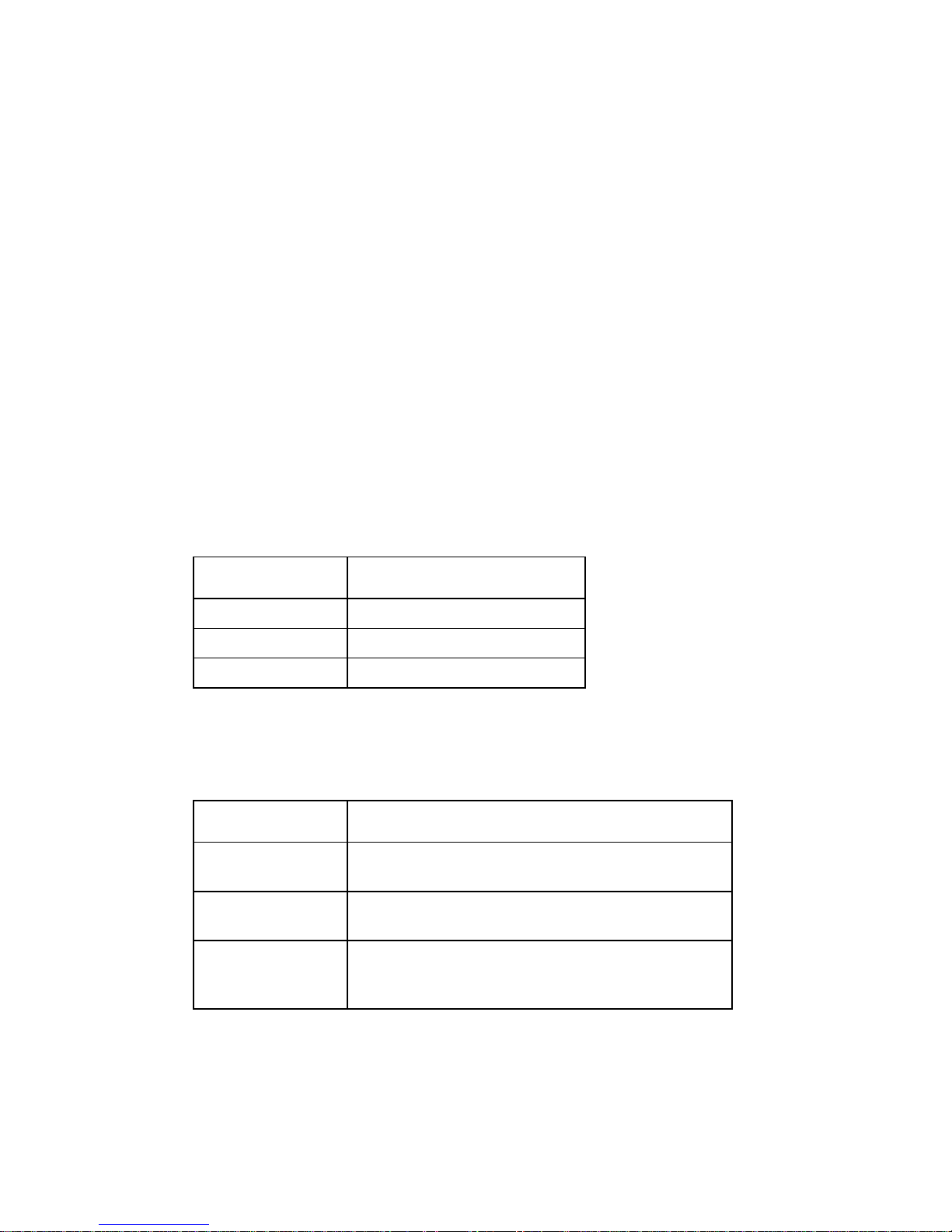
Important! The wires in this mains lead are coloured in accordance with the
following code.
Colour
Mains lead wire
Green and yellow
Earth
Blue
Neutral
Brown
Live
Connecting the mains lead
Mains lead wire colours may not correspond with the colour markings of the
terminals in your plug.
IF wire colour is
Connect it to…
Blue
Neutral terminal. Note: The Neutral terminal is
typically marked N or coloured black.
Brown
Live terminalNote: The Live terminal is typically
marked L or coloured red.
Green and yellow
Earth terminal. Note: The Earth terminal is typically
marked E (or marked with the safety earth symbol ( ),
or coloured green and yellow.
Page 15

Contents
Safety Precautions v
Safety Precautions ................................................................................................................ viii
Important Notices for Customers in the United Kingdom ............................................. xiv
About This Manual xxiii
Objective ................................................................................................................. xxiii
Audience ................................................................................................................ xxiii
Required Knowledge ............................................................................................ xxiii
Chapter 1 Getting Started 1
Installation ................................................................................................................................ 2
Cooling ......................................................................................................................... 2
Rack Information ........................................................................................................ 2
Power Connection ....................................................................................................... 3
AC Power Connection ................................................................................................ 3
DC Power Connection (if equipped) ........................................................................ 4
Quick Start Guide .................................................................................................................... 5
Maintenance.............................................................................................................................. 6
Chapter 2 Controls and Configuration 7
D9887B Receiver ....................................................................................................................... 8
Front of Unit ................................................................................................................ 8
Rear of Unit .................................................................................................................. 8
Front Panel Display Layout .................................................................................................... 9
Front Panel Indicators ................................................................................................ 9
Error Logic .............................................................................................................................. 11
Input Error Logic ...................................................................................................... 11
Decoder Error Logic ................................................................................................. 11
Temperature Error Logic ......................................................................................... 11
Fan Error Logic .......................................................................................................... 12
SNMP Traps ............................................................................................................................ 13
Input/Output Slot Organization ......................................................................................... 14
Chapter 3 Option Cards Overview 15
Overview of the Option Cards ............................................................................................. 16
VSB/QAM Receiver Option .................................................................................... 17
Serial Transport Stream I/O (DVB-ASI/SMPTE 310M) Option ........................ 17
Page 16

xvi 78-4043743-01 Rev A
Video Output (1 RGBHV/YPbPr, 1 Composite) Option..................................... 17
Audio Output (Dolby E, AES Digital, Analog) Option ....................................... 17
Video Output (2 HD/SD-SDI, 1 RGBHV/YPbPr/Composite) Option ............ 18
Dual Input DVB-S/DVB-S2 Receiver Option ....................................................... 18
Dual Input ASM Receiver Option .......................................................................... 18
Video Output (2 HD/SD-SDI, 1 RGBHV/YPbPr/Comp) Option .................... 18
Dual Input COFDM Receiver Option .................................................................... 19
Quad Input DVB-S/DVB-S2 with LNB Power Option ....................................... 19
CAM Decryption Option ......................................................................................... 19
Dual MPEG over IP Input/UDP Output Option ................................................. 19
Chapter 4 Using the Front Panel to Configure the D9887B HDTV
Modular Receiver 21
Input Option – Active Input and Backup Configuration Selection ................................ 23
General Information ................................................................................................. 23
Supported Option Cards .......................................................................................... 23
Description ................................................................................................................. 23
Changing the Active Input ...................................................................................... 23
Configuring Input Backup Settings ........................................................................ 24
8VSB/QAM Receiver Option ............................................................................................... 26
General Information ................................................................................................. 26
To Edit the Option Card Input Settings ................................................................. 26
Channel ...................................................................................................................... 27
Modulation ................................................................................................................ 27
Channel Bands ........................................................................................................... 27
Set Low Signal and MER Error Levels ................................................................... 28
Reset FEC Error Counters ........................................................................................ 28
Serial Transport Stream Input/Output (DVB-ASI/SMPTE 310M) Option ................... 29
General Information ................................................................................................. 29
To Edit the Input Option .......................................................................................... 29
Input Type.................................................................................................................. 30
Video Output (1 RGBHV/YPbPr, 1 Composite) Option .................................................. 31
General Information ................................................................................................. 31
Output Control .......................................................................................................... 31
Video Settings ............................................................................................................ 31
Composite VBI Assignment .................................................................................... 35
Overlay Settings ........................................................................................................ 36
Overlay (Closed Caption) ........................................................................................ 37
Overlay (Table) .......................................................................................................... 38
Overlay (Service) ....................................................................................................... 39
Overlay (Subtitle) ...................................................................................................... 39
Genlock Offset ........................................................................................................... 39
Small Format Display ............................................................................................... 41
Audio Output (Dolby E, AES Digital, Analog) Option .................................................... 43
General Information ................................................................................................. 43
Output Control .......................................................................................................... 43
Page 17

Digital Audio Settings .............................................................................................. 44
Analog Audio Settings ............................................................................................. 44
Output Level .............................................................................................................. 45
Dual Video Output (2 SDI, 1 RGBHV/YPbPr/Composite) Option ............................... 46
General Information ................................................................................................. 46
Output Control .......................................................................................................... 46
Video Settings ............................................................................................................ 46
HD Settings ................................................................................................................ 49
SD Settings ................................................................................................................. 52
Genlock Offset ........................................................................................................... 56
Overlay Settings ........................................................................................................ 58
Overlay (Table) .......................................................................................................... 59
Overlay (Service) ....................................................................................................... 60
Overlay (Subtitle) ...................................................................................................... 61
Small Format Display ............................................................................................... 61
Dual Input DVB-S/DVB-S2 Receiver Option .................................................................... 63
General Information ................................................................................................. 63
To Edit the Option Card Input Settings ................................................................. 63
Source ......................................................................................................................... 64
Input A ....................................................................................................................... 64
Input B ........................................................................................................................ 65
Dual Input ASM Receiver Option ....................................................................................... 67
General Information ................................................................................................. 67
To Edit the Option Card Input Settings ................................................................. 67
Source ......................................................................................................................... 68
Input A ....................................................................................................................... 68
Input B ........................................................................................................................ 70
Video Output (2 HD/SD-SDI, 1 RGBHV/YPbPr/Comp) Option.................................. 72
General Information ................................................................................................. 72
Output Control .......................................................................................................... 72
Video Settings ............................................................................................................ 72
HD SDI VANC Embedding ..................................................................................... 76
SD SDI VANC Embedding ...................................................................................... 77
Composite VBI Assignment .................................................................................... 78
HD/SD Genlock Offset ............................................................................................ 79
Vertical........................................................................................................................ 79
Horizontal .................................................................................................................. 80
Dual Input COFDM Receiver Option ................................................................................. 81
General Information ................................................................................................. 81
To Edit the Option Card Input Settings ................................................................. 81
Source ......................................................................................................................... 82
Input A ....................................................................................................................... 82
Input B ........................................................................................................................ 83
Quad Input DVB-S/DVB-S2 Receiver with LNB Power Option .................................... 85
General Information ................................................................................................. 85
To Edit the Option Card Input Settings ................................................................. 85
Source ......................................................................................................................... 86
Page 18

xviii 78-4043743-01 Rev A
Source Settings .......................................................................................................... 86
DVB Mode .................................................................................................................. 87
Enabling Advanced DVB-S2 Capabilities.............................................................. 87
LNB Power ................................................................................................................. 89
22 kHz Tone ............................................................................................................... 89
Tuning Frequency ..................................................................................................... 89
Symbol Rate ............................................................................................................... 91
CA Decryption Option .......................................................................................................... 92
General Information ................................................................................................. 92
CAM Decryption Setup ............................................................................................ 92
BISS Setup .................................................................................................................. 95
Dual MPEG over IP Input/ UDP Output Option ............................................................. 98
General Information ................................................................................................. 98
Menu Control ............................................................................................................ 98
To Edit the Option Card Input Settings ............................................................... 100
Group Selection Settings ........................................................................................ 100
Receive 1 ................................................................................................................... 102
Receive 2 ................................................................................................................... 107
Reset Counters ......................................................................................................... 110
Output Control ........................................................................................................ 111
MPEG-2/MPEG-4 4:2:0 Decoder (1 Video, 2 Audio) Option ........................................ 116
General Information ............................................................................................... 116
Decoder Setup ......................................................................................................... 116
Tune Mode ............................................................................................................... 117
PID Lock Mode ........................................................................................................ 117
Priority Mode .......................................................................................................... 119
No PSI Mode ............................................................................................................ 121
Auto Mode ............................................................................................................... 125
SDI Audio Embedding ........................................................................................... 125
Audio 1 Setup .......................................................................................................... 126
Source ID Setup ....................................................................................................... 128
Buffer Mode Video Latency................................................................................... 129
MPEG-2 Decoder 4:2:2 with Genlock (1 Video, 4 Audio) Option ................................. 131
General Information ............................................................................................... 131
Decoder Setup ......................................................................................................... 131
Tune Mode ............................................................................................................... 132
SDI Audio Embedding ........................................................................................... 139
Audio 1 Setup .......................................................................................................... 140
Active Errors ......................................................................................................................... 142
Active Errors Display ............................................................................................. 142
Event Log .............................................................................................................................. 143
Event Logging Setup .............................................................................................. 143
Event Log Display................................................................................................... 143
Clear Error List ........................................................................................................ 144
Password Strength ............................................................................................................... 146
Character Type ........................................................................................................ 146
Repeats ..................................................................................................................... 146
Page 19

Not User ID .............................................................................................................. 147
Not In List ................................................................................................................ 147
Network Security ................................................................................................................. 149
HTTP ......................................................................................................................... 149
HTTPS ....................................................................................................................... 149
SNMP ........................................................................................................................ 150
SSH ............................................................................................................................ 150
ICMP ......................................................................................................................... 150
Network Setup ..................................................................................................................... 152
Static IP Address ..................................................................................................... 152
IP Address/Subnet Mask/Gateway .................................................................... 153
DHCP ........................................................................................................................ 154
Panel Lock ............................................................................................................................. 155
Locking ..................................................................................................................... 155
Unlocking ................................................................................................................. 156
SNMP Configuration ........................................................................................................... 157
RO Community Setup ............................................................................................ 157
RW Community Setup ........................................................................................... 159
Genlock Reference ............................................................................................................... 161
Setting Genlock Format .......................................................................................... 161
SMPTE 333M Configuration .............................................................................................. 162
System Information ............................................................................................................. 163
Versions .................................................................................................................... 163
Profiles ...................................................................................................................... 164
Hardware ................................................................................................................. 165
Temperature ............................................................................................................ 166
Time .......................................................................................................................... 166
Feature Licensing ................................................................................................................. 168
To View the Current Licensing ............................................................................. 168
To Enter the License Key ....................................................................................... 168
Chapter 5 Using the Web Client to Configure the D9887B
Receiver 169
Login ...................................................................................................................................... 170
Status Indicators ................................................................................................................... 171
Configuration ....................................................................................................................... 172
Input Setup .............................................................................................................. 172
Services Setup .......................................................................................................... 173
Output Setup ........................................................................................................... 176
PSIP Information ..................................................................................................... 176
Unit ........................................................................................................................................ 178
Active Errors ............................................................................................................ 178
Event Logging ......................................................................................................... 178
Unit Date/Time ....................................................................................................... 179
SNMP MIB Modules ............................................................................................... 180
SNMP Settings ......................................................................................................... 180
Page 20

xx 78-4043743-01 Rev A
SMPTE-333M ........................................................................................................... 181
Profiles ................................................................................................................................... 182
Saving a Profile........................................................................................................ 182
Deleting a Profile..................................................................................................... 183
Renaming a Profile ................................................................................................. 184
Applying a Saved Profile ....................................................................................... 185
Viewing a Saved Profile ......................................................................................... 185
Downloading a Saved Profile................................................................................ 186
Uploading a Saved Profile ..................................................................................... 187
Web Passwords .................................................................................................................... 188
Password Strength ............................................................................................................... 189
Network Services ................................................................................................................. 190
Reset Unit .............................................................................................................................. 191
Software Updates ................................................................................................................. 192
Diagnostics ............................................................................................................................ 193
Processes .................................................................................................................. 193
Network Interface Information ............................................................................. 193
About ..................................................................................................................................... 195
Feature Licensing ................................................................................................................. 196
Follow these steps to upgrade ............................................................................... 196
Chapter 6 Customer Information 199
Appendix A Error/Event List 201
Error or Event List ............................................................................................................... 202
General ..................................................................................................................... 202
Video ......................................................................................................................... 203
Audio ........................................................................................................................ 204
System....................................................................................................................... 204
Page 21

Appendix B Specifications 205
D9887B receiver – base unit ................................................................................................ 206
8VSB/QAM Receiver Option ............................................................................................. 208
Serial TS Input/Output (DVB-ASI /SMPTE 310M) Option .......................................... 209
Video Output (1 RGBHV/YPbPr, 1 Composite) Option ................................................ 210
Audio Output (Dolby E, AES Digital, Analog) Option .................................................. 212
Video Output (2 SDI, 1 RGBHV/YPbPr/Composite) Option ....................................... 214
Dual Input DVB-S2 Receiver Option ................................................................................ 216
Dual Input ASM Receiver Option ..................................................................................... 218
Video Output (2 SDI, 1 RGBHV/YPbPr/Composite) Option ....................................... 219
Dual Input COFDM Receiver Option ............................................................................... 222
Quad Input DVB-S/DVB-S2 Receiver with LNB Power Option .................................. 223
CAM Decryption Option .................................................................................................... 225
Dual Input MPEG over IP Receiver/UDP Output Option ............................................ 226
MPEG-2/MPEG-4 Decoder (1 Video, 2 Audio) Option ................................................. 227
MPEG-2 Decoder with Genlock (1 Video, 4 Audio) Option .......................................... 229
MPEG-2/MPEG-4 Decoder (1 Video, 2 Audio) Option ................................................. 230
Appendix C Pinout Information 233
Pinout Information .............................................................................................................. 234
Audio Output (Dolby E, AES Digital, Analog) Option ..................................... 234
Video Output (2 HD/SD-SDI, 1 RGBHV/YPbPr/Composite) Option
and Video Output (2 HD/SD-SDI, 1 RGBHV/YPbPr/Comp) Option ........ 234
Appendix D Coordinated Universal Time 237
Coordinated Universal Time .............................................................................................. 238
Appendix E D9887B Receiver Audio Explanation 241
Audio Setup .......................................................................................................................... 242
Audio Output Settings ........................................................................................................ 244
Digital Audio Measurements ............................................................................................. 245
Analog Audio Measurements ............................................................................... 245
General Audio Setup for Measurements ............................................................. 246
Appendix F Compliance 247
Compliance ........................................................................................................................... 248
FCC Notices ............................................................................................................. 248
Industry Canada Notice ......................................................................................... 248
Unauthorized Modifications ................................................................................. 248
Page 22

xxii 78-4043743-01 Rev A
Declaration of Conformity .................................................................................................. 249
Glossary 251
Index 259
Page 23

About This Manual
78-4043743-01 Rev A xxiii
About This Manual
Objective
This manual describes how to install, use, and maintain the Cisco® D9887B HDTV
Modular Receiver.
Note: The manual describes all available options for the D9887B receiver. Your
D9887B receiver may only have some of the features described in this manual.
Audience
The audience includes users (operators) and service personnel who are responsible
for the installation, configuration, operation, monitoring, and service of the D9887B
receiver.
Required Knowledge
To use this documentation, the user should have a basic knowledge of the
technology used in relation to this product. Service personnel should have
additional skills and be familiar with cabling, electronic circuitry, and wiring
practices.
This manual is intended for operators who are responsible for the configuration,
remote operation, and maintenance of the D9887B receiver.
Page 24

Page 25

78-4043743-01 Rev A 1
Overview
This chapter provides installation and a quick setup for your D9887B
receiver.
1 Chapter 1
Getting Started
In This Chapter
Installation ............................................................................................... 2
Quick Start Guide ................................................................................... 5
Maintenance ............................................................................................ 6
Page 26
Chapter 1 Getting Started
2 78-4043743-01 Rev A
Installation
Cooling
The D9887B receiver is cooled via forced induction through the front of the unit and
exhausted through the vents on either side. The D9887B receiver is equipped with a
temperature controlled status indicator. If the temperature inside the unit exceeds
70° C, the red “Error” LED will illuminate and a description of the error will appear
in the “Error List.”
Rack Information
The D9887B receiver is intended to be mounted in a standard 19" rack. It occupies 1U
of rack space and the connections are all on the rear of the unit.
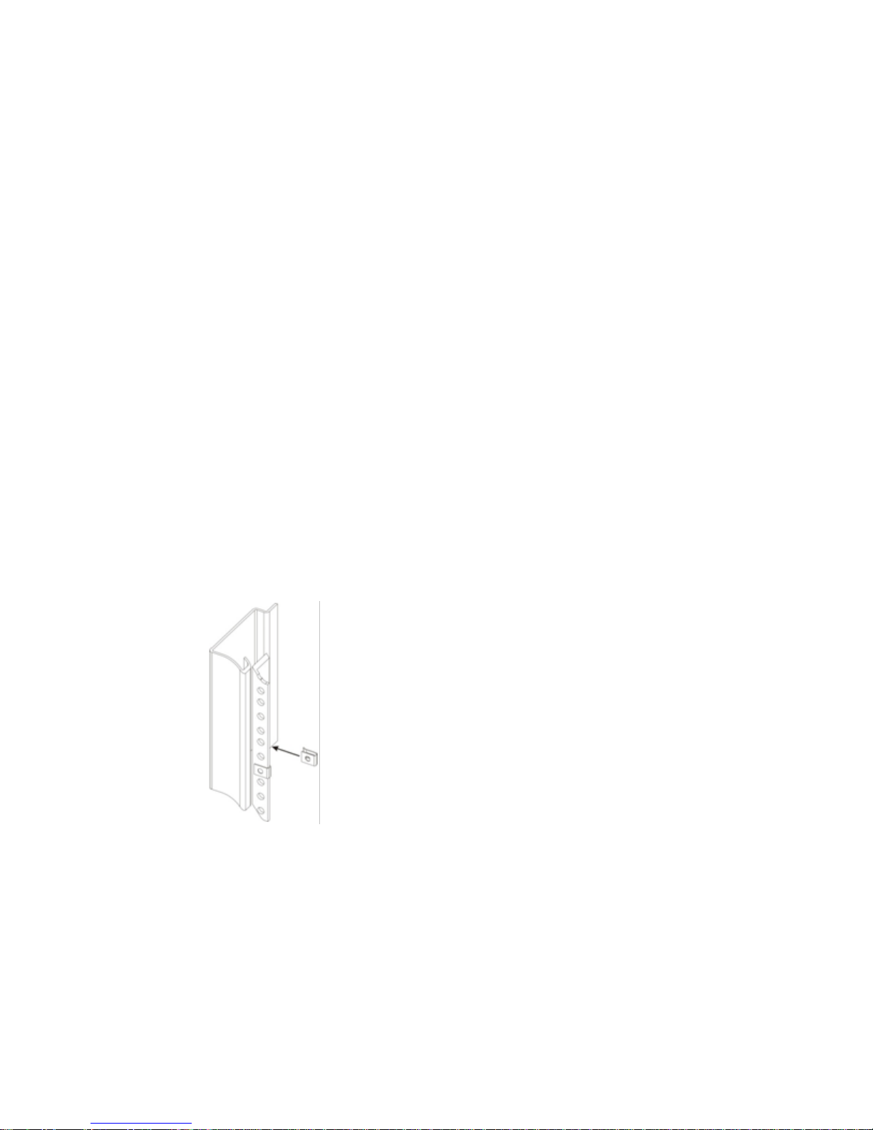
Rack Installation
To install the D9887B receiver into a rack, use the following steps:
1 Determine the desired position in the rack for the D9887B receiver, making sure
that the air intake on the front of the unit and the exhausts on the sides of the
unit will not be obstructed.
2 Insert the rack mount clips into place over the mounting holes in the rack.
3 Slide the D9887B receiver into position in the rack.
Page 27
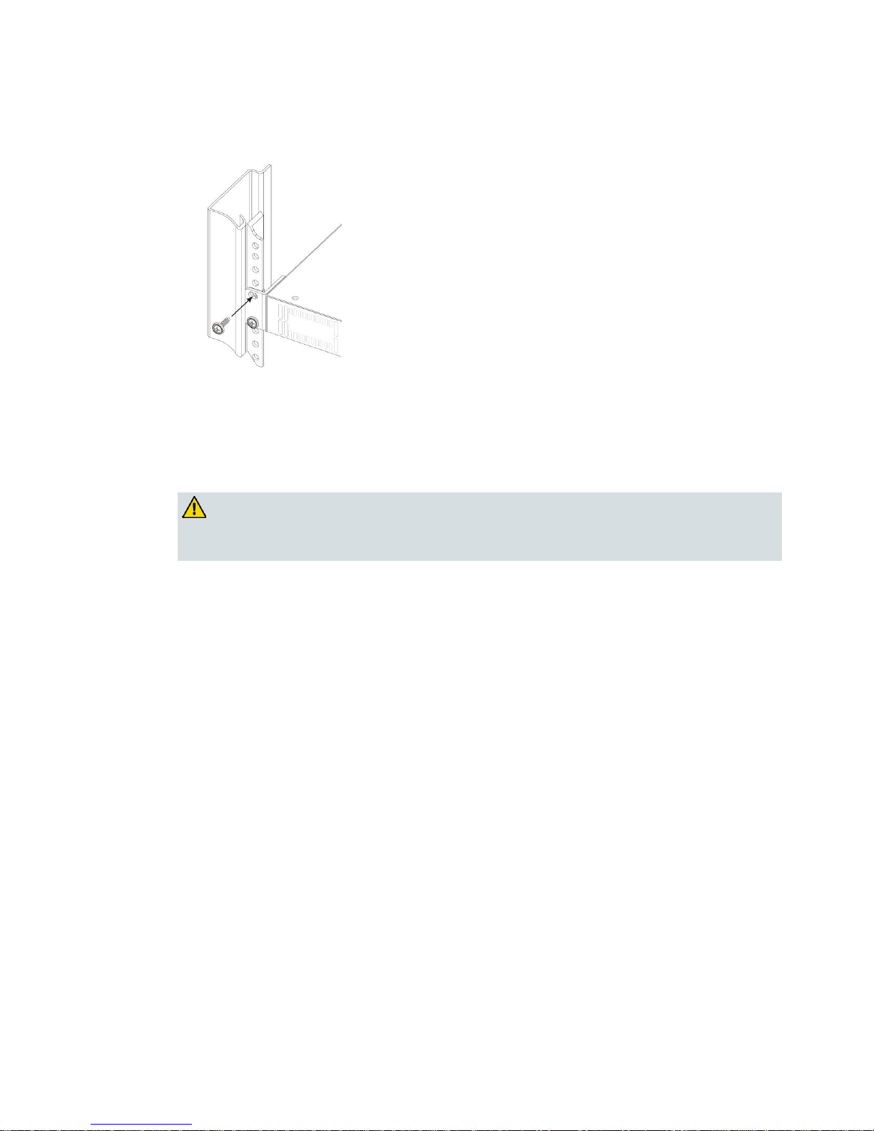
Installation
78-4043743-01 Rev A 3
4 Secure the D9887B receiver to the rack by installing the four supplied screws
through the front mounting holes and tightening.
Power Connection
Using the proper power connections is vital to the safe operation of the D9887B
receiver. Only use the supplied 3-prong power connector or one with equal
specifications.
WARNING:
NEVER tamper with or remove the third prong grounding pin. This could cause
damage to the D9887B receiver, personnel, or property.
AC Power Connection
The D9887B receiver is intended for use on either 120V or 240V systems. The power
supply will automatically detect the system it is connected to. To hook up the power,
use the following steps:
1 Locate the AC power cord included with the D9887B receiver.
2 Plug the female end of the power cord (end with no prongs) into the back of the
unit.
3 Locate a protected outlet (usually inside of the rack) to plug the male end of the
power cable into.
Page 28

Chapter 1 Getting Started
4 78-4043743-01 Rev A
DC Power Connection (if equipped)
Using the proper power connections is vital to the safe operation of the D9887B
receiver. The D9887B receiver is intended for use in 40-65 VDC systems. The power
supply will automatically detect the system it is connected to. When installing the
D9887B receiver, the power supply MUST be used in conjunction with an overcurrent protective device rated at 50 V, 5 A, type: Slow-blo, as part of batterysupply circuit.
WARNING:
Failure to include an over-current protective device could cause damage to the
D9887B receiver, personnel, or property.
Page 29

Quick Start Guide
78-4043743-01 Rev A 5
Quick Start Guide
To get the D9887B receiver up and running there is a few things that need to be
done.
1 Select the desired input as active.
2 Setup the decoder with the proper PIDs.
3 Setup the desired output(s).
The easiest way to set these options up is to refer to Using the Front Panel to
Configure the D9887B HDTV Modular Receiver (on page 21).
Page 30

Chapter 1 Getting Started
6 78-4043743-01 Rev A
Maintenance
The D9887B receiver is virtually a maintenance-free piece of equipment. There are no
user serviceable parts on the inside of the unit, however it is recommended that the
user cleans the intake filter on the front right side of the unit on a regular basis to
ensure an unobstructed cool air intake. To remove the filter, open the door on the
front side of the unit and remove.
Page 31

78-4043743-01 Rev A 7
Overview
This chapter describes the controls in the D9887B HDTV Modular
Receiver. It describes the most common applications and interfaces of
the receiver.
2 Chapter 2
Controls and Configuration
In This Chapter
D9887B Receiver ...................................................................................... 8
Front Panel Display Layout ................................................................... 9
Error Logic ............................................................................................. 11
SNMP Traps ........................................................................................... 13
Input/Output Slot Organization ........................................................ 14
Page 32

Chapter 2 Controls and Configuration
8 78-4043743-01 Rev A
D9887B Receiver
Front of Unit
Rear of Unit
Page 33

Front Panel Display Layout
78-4043743-01 Rev A 9
Front Panel Display Layout
The following figure shows a typical screen on the front panel. Several important
features have been circled and noted below. These features are common to all
screens and assist when navigating, viewing, and editing unit information. The
Home button will return the user to the home level while in any screen. To edit a
selected parameter, press the Enter button. Once a parameter has been changed,
press the Enter button again in order for the change to take effect on the unit. Press
the Exit button to leave the edit mode without changes taking effect.
1 Icons indicate which control buttons are currently valid for entry.
2 Screen title.
3 Cursor shows which line is active.
4 When editing, active character or item is highlighted.
Front Panel Indicators
The D9887B receiver has four internal error parameters: INPUT, DECODER, FAN,
and TEMPERATURE. These parameters can be monitored locally or remotely.
Locally, the unit’s status can be checked by visually looking at the INPUT LED and
the ERROR LED on the front panel, then use the "Error List" under the Menu button
to pinpoint the error. Remotely, the unit’s status can be checked by using the web
client and looking at the status icons on the top of the main window. To see a
detailed list of errors, click on the Unit tab from the web client.
Page 34

Chapter 2 Controls and Configuration
10 78-4043743-01 Rev A
The INPUT LED indicates the presence of a stream at the user-selected input.
“Stream present” is represented by a green INPUT LED while “stream NOT
present” is represented by a dark INPUT LED.
The ERROR LED represents the combined status of the unit’s error indicators. If
INPUT, DECODER, TEMP, or FAN status is in the error state, the LED will be red. If
all error indicators are good, the LED will be dark.
Page 35

Error Logic
78-4043743-01 Rev A 11
Error Logic
Input Error Logic
The input status is based on the selected input card’s status and the transport error
indicator bit in the transport stream being decoded. For example, if the current input
is VSB, the input status is based on: VSB receiver lock, RF channel level, and the
MER level. The RF channel and MER thresholds can be set by the user. If the unit
detects the presence of the transport error bit in a transport packet header, the input
status will be an error for 0.5 seconds each time the TS error bit is set. The system
must detect a constant cadence of sync bytes (0x47h) every 188 bytes and detect a
valid PAT at least every 500 ms in order for the INPUT LED to illuminate.
Decoder Error Logic
The decoder error indicator is based on the decoder’s ability to decode what the user
has requested. The input status will be alarmed differently depending on the current
decoding mode:
In "Auto Mode," the decoder status will be good unless the Video or Audio
decoders cannot decode a stream. For example: a stream defines program 4 to
have video on PID 52. If PID 52 is not actually present in the stream, or is undecodable, the decoder status will be in the error state. This is true for all modes.
In "PID Lock Mode," the decoder status will be good if all of the PIDs entered by
the user, for video and audio, are being decoded by the unit. If the user wants
nothing to be decoded, the PID should be set to 0. If the user enters a PID which
is not present or cannot be decoded, the decoder status will be in the error state.
In "Program Priority Mode," the decoder status will be good if any priority is
currently active and the Audio and Video represented by that priority are being
decoded. If the PMT for a selected program lists a video or audio PID, but the
decoder cannot decode that PID, the indicator will be in the error state. If the
user enters an index for a priority that does not exist in the PMT, the indicator
will still be good because the decoder will be set to decode nothing on that audio
output.
Temperature Error Logic
The temperature error indicator is based on the correct operation of the unit. If the
unit’s internal temperature exceeds 70 °C, the temperature status will be in the error
state.
Page 36

Chapter 2 Controls and Configuration
12 78-4043743-01 Rev A
Fan Error Logic
If the fan in the unit fails, the fan status will be in the error state. The fan status will
be good as long as the fan is spinning at the proper RPM.
Page 37

SNMP Traps
78-4043743-01 Rev A 13
SNMP Traps
The unit contains separate SNMP Traps for Fan Status, Temperature Status, Decoder
Status, Input Status, and IP Receive Group. Whenever any item changes state, a trap
is sent to the configured host.
Page 38

Chapter 2 Controls and Configuration
14 78-4043743-01 Rev A
Input/Output Slot Organization
The D9887B receiver’s modular design allows many different input/output
configurations. An indexing system is used to identify module slots for
configuration and monitoring reference. The bottom row of slots is numbered 1-1
through 1-4 (left to right). The top row is numbered 2-1 through 2-4 as shown.
Page 39

78-4043743-01 Rev A 15
Overview
This chapter includes a brief overview of the different option cards
that are available for the D9887B receiver. There are descriptions of
each card as well as pictures of the various inputs and outputs for each
card.
3 Chapter 3
Option Cards Overview
In This Chapter
Overview of the Option Cards ............................................................ 16
Page 40

Chapter 3 Option Cards Overview
16 78-4043743-01 Rev A
Overview of the Option Cards
The following is a list of the option cards available for the D9887B receiver:
Option Card Image
Option Card Type
8VSB/QAM Receiver Option
Serial Transport Stream I/O (DVB-ASI/SMPTE
310M) Option
Video Output (1 RGBHV/YPbPr, 1 Composite)
Option
Audio Output (Dolby® E, AES Digital, Analog)
Option
Video Output (2 HD/SD-SDI, 1
RGBHV/YPbPr/Composite) Option
Dual Input DVB-S/DVB-S2 Receiver Option
Dual Input ASM Receiver Option
Video Output (2 HD/SD-SDI, 1
RGBHV/YPbPr/Comp) Option
Dual Input COFDM Receiver Option
Quad Input DVB-S/DVB-S2 with LNB Option
CAM Decryption Option
Dual MPEG over IP Input/UDP Output Option
Page 41

Overview of the Option Cards
78-4043743-01 Rev A 17
VSB/QAM Receiver Option
This card will receive a TS that is demodulated from an 8 VSB signal or it will
demodulate a QAM 64B or QAM 256B RF input. With an 8 VSB input, the card will
tune to channels 2 – 69. With a QAM input, the card will tune to channels 2 – 134 in
three cable frequency bands (FCC, IRC, and HRC). The D9887B receiver will show a
valid input if the following conditions are met: the receiver equalizer and the FEC
are locked. If the RF level is lower than the "Low Warning Setting" or the MER is
lower than the "Low MER Warning Setting," the red "Error" LED will illuminate on
the front panel and there will be an error recorded in the Error List.
Serial Transport Stream I/O (DVB-ASI/SMPTE 310M) Option
This card will receive a TS from either a DVB-ASI input or a SMPTE-310M input.
Only one format may be selected at a time. For an ASI input, the bitrate of the TS
must be between 1.5 Mb/s and 160 Mb/s. For a SMPTE-310M input, the bitrate of
the TS must be 19.392658 Mb/s. The selected input format will also be the output
format. It can also be used as a TS output for any of the other input cards.
Video Output (1 RGBHV/YPbPr, 1 Composite) Option
An analog only video output card that can output either high definition or standard
definition formats. Two outputs are on the card: one BNC for composite (NTSC &
PAL) and one 15-pin D-sub for component (RGBHV or YPbPr). The card outputs an
SD or HD signal, one at a time. Closed caption (NTSC), detected in the transport
stream, can be inserted on line 21 of the composite (NTSC video) output.
Audio Output (Dolby E, AES Digital, Analog) Option
This card allows the output of both Digital-AES and analog audio. Each digital audio
output can be set to either Raw or PCM. In Raw, the compressed audio for the
selected PID is passed through to the digital output. Typically, this setting is used to
pass-through the Dolby AC-3 compressed digital signal. When the digital audio
output is set to PCM, two-channel linear coded PCM AES/EBU audio is output to
the digital output. The analog output provides two-channel (L, R) decoded analog
audio from the selected audio processor. The two audio processors on the decoder
board, feeding the two digital outputs, can process or decode Dolby AC-3, MPEG
Layer 1, or MPEG Layer 2 formats. The audio processor will self-sense which type of
audio is in the TS. It also has a Dolby E parsing feature.
Page 42

Chapter 3 Option Cards Overview
18 78-4043743-01 Rev A
Video Output (2 HD/SD-SDI, 1 RGBHV/YPbPr/Composite) Option
A versatile video output card. It provides two user selectable serial digital (SMPTE259M, or SMPTE-292M) outputs and one component RGBHV or YPbPr/Composite
NTSC & PAL output. Four pairs of audio can be embedded into the serial output on
group 1, and 2. Closed captioning found within the transport (608/708B) can be
embedded into the serial video output. NTSC closed caption, detected in the
transport stream, can be inserted on line 21.
Dual Input DVB-S/DVB-S2 Receiver Option
This card will input a satellite L-band (950 MHz – 2150 MHz) signal for
demodulation of KU-band or C-band DVB-S QPSK signals or DVB-S2 QPSK/8PSK
signals. The symbol rate ranges from 1 MSym/s to 45 MSym/s for DVB-S and 1-30
MSym/s for DVB-S2. This card does not provide any power to the dish LNB. The
"Input" LED will only illuminate if the card detects frequency, symbol rate, FEC lock
(Carrier Lock), and TS sync (Sync Lock). The card provides A and B inputs, which
may be independently configured, but only one may be active at a time.
Dual Input ASM Receiver Option
This card will input a satellite L-band (950 MHz – 2150 MHz) signal for
demodulation of KU-band, C-band, or X-band DVB-QPSK, 8PSK, or Adv-QPSK
signals. All these modes are available using Turbo Coded forward error correction.
The DVB-QPSK mode also supports legacy DVB FEC. The symbol rate ranges from
0.256 MSym/s to 30 MSym/s for all modulation types. This card does not provide
any power to the dish LNB. The "Input" LED will only illuminate if the card detects
frequency, symbol rate, FEC lock (Carrier Lock), and TS sync (Sync Lock). The card
provides A and B inputs, which may be independently configured, but only one may
be active at a time.
Video Output (2 HD/SD-SDI, 1 RGBHV/YPbPr/Comp) Option
A versatile video output card. It provides two user selectable serial digital (SMPTE
259M, or SMPTE 292M) outputs and one component RGBHV or YPbPr/Composite
NTSC & PAL output. Eight pairs of audio can be embedded into the serial output on
group 1, 2, 3 and 4. Closed captioning found within the transport (608/708B) can be
embedded into the serial video output. NTSC closed caption, detected in the
transport stream, can be inserted on line 21.
Note: This card requires the MPEG Decoder with Genlock (1 Video, 4 Audio) board.
Page 43

Overview of the Option Cards
78-4043743-01 Rev A 19
Dual Input COFDM Receiver Option
This card will input a (49 – 861 MHz) COFDM signal for use in electronic news
gathering (U.S.) or any COFDM Terrestrial Broadcast (DVB-T, European)
applications. The card provides A and B inputs, which may be independently
configured, but only one may be active at a time.
Quad Input DVB-S/DVB-S2 with LNB Power Option
This card will input a satellite L-band (950 MHz – 2150 MHz) signal for
demodulation of KU-band or C-band DVB-S QPSK signals or DVB-S2 QPSK/8PSK
signals. The symbol rate ranges from 1 MSym/s to 45 MSym/s for both DVB-S and
DVB-S2. This card provides LNB power and 22 kHz control tone to the active input.
This card has advanced feature options of multistream input, support for VCM, and
support for 16APSK and 32APSK modulation. The "Input" LED will only illuminate
if the card detects frequency, symbol rate, FEC lock (Carrier Lock), and TS sync
(Sync Lock). The card provides A, B, C and D inputs, which may be independently
configured, but only one may be active at a time.
CAM Decryption Option
This is a factory installed slot that will allow for up to two CAM cards to be installed
at a time, providing the D9887B receiver the ability to decrypt Conditional Access
transport streams.
Dual MPEG over IP Input/UDP Output Option
This card is a dual purpose card in that it can receive and/or transmit from the
internal TS bus, MPEG over IP. It has two physical connectors that can be configured
independently. Up to two multicasts can be subscribed to, allowing for a backup
multicast to be chosen and two UDP mirrored unicasts or multicasts can be
transmitted to allow for redundancy.
Example Configurations
IP Address Selection
"Leave" IGMP V2 & V3
Multicast/Unicast
Unicast: X.X.X.X – 223.255.255.255
Filter Mode: Include
Multicast: 224.X.X.X – 239.255.255.255
IP list: empty
Suggested Multicast Range: 239.192.X.X
"Join" IGMP V2 & V3
Multicast/Unicast
Suggested Port Selection
Filter Mode: Exclude
Choose a port number of 5000 or more
IP list: empty
Choose even numbered ports
Page 44

Chapter 3 Option Cards Overview
20 78-4043743-01 Rev A
If using FEC the following example
applies
"Join Filtered" IGMP V3
Multicast/Unicast
– Destination port = 5000
Filter Mode: Include
– Column FEC = 5002
IP: X.X.X.X Or
– Row REC = 5004
Filter Mode: Exclude
IP: X.X.X.X
– Next available multicast port =
5006
Page 45

78-4043743-01 Rev A 21
Overview
This chapter describes how to navigate through the configuration
menus on the front panel of the D9887B receiver.
Note: All instructions in this manual are based on the unit software
version 7.3.X. Newer versions of software, when released, may
operate slightly different in regards to menus and configuration.
4 Chapter 4
Using the Front Panel to
Configure the D9887B HDTV
Modular Receiver
Page 46

Chapter 4 Using the Front Panel to Configure the D9887B HDTV Modular Receiver
22 78-4043743-01 Rev A
In This Chapter
Input Option – Active Input and Backup Configuration
Selection ................................................................................................. 23
8VSB/QAM Receiver Option .............................................................. 26
Serial Transport Stream Input/Output (DVB-ASI/SMPTE
310M) Option ......................................................................................... 29
Video Output (1 RGBHV/YPbPr, 1 Composite) Option ................ 31
Audio Output (Dolby E, AES Digital, Analog) Option ................... 43
Dual Video Output (2 SDI, 1 RGBHV/YPbPr/Composite)
Option ..................................................................................................... 46
Dual Input DVB-S/DVB-S2 Receiver Option ................................... 63
Dual Input ASM Receiver Option ...................................................... 67
Video Output (2 HD/SD-SDI, 1 RGBHV/YPbPr/Comp)
Option ..................................................................................................... 72
Dual Input COFDM Receiver Option ................................................ 81
Quad Input DVB-S/DVB-S2 Receiver with LNB Power Option ... 85
CA Decryption Option ......................................................................... 92
Dual MPEG over IP Input/ UDP Output Option ............................ 98
MPEG-2/MPEG-4 4:2:0 Decoder (1 Video, 2 Audio) Option ....... 116
MPEG-2 Decoder 4:2:2 with Genlock (1 Video, 4 Audio)
Option ................................................................................................... 131
Active Errors ........................................................................................ 142
Event Log ............................................................................................. 143
Password Strength .............................................................................. 146
Network Security ................................................................................ 149
Network Setup .................................................................................... 152
Panel Lock ............................................................................................ 155
SNMP Configuration .......................................................................... 157
Genlock Reference .............................................................................. 161
SMPTE 333M Configuration ............................................................. 162
System Information ............................................................................ 163
Feature Licensing ................................................................................ 168
Page 47

Input Option – Active Input and Backup Configuration Selection
78-4043743-01 Rev A 23
Input Option – Active Input and Backup
Configuration Selection
General Information
The selection of the Active input and configuration of the Backup input are
described in this section.
Supported Option Cards
8VSB/QAM Receiver option, Serial Transport Stream I/O (DVB-ASI/SMPTE-310M)
option, High Bit Rate ASI Input option, Dual Input DVB-S/DVB S2 Receiver option,
Dual Input ASM Receiver option, Dual Input COFDM Receiver option, Quad Input
DVB-S/DVB-S2 with LNB option, MPEG over IP Input/Output option, and Dual
MPEG over IP Input/UDP Output option.
Description
The Active input specifies the card that is being used as the input option. The
Backup configuration enables/disables the switching to a backup input, defines the
Primary Input and Backup Input, when to restore to the Primary Input and a
timeout before switching to the Backup Input, or restoring to the Primary Input.
Changing the Active Input
To set an Active Input, use the following steps:
1 Press the Input button.
Note: For Configuration 2 units, select RDS1 or RDS2, then press Enter.
2 Press the Enter button to edit the Active Input. The current Active Input is
displayed along with a "(P)" for Primary or "(B)" for Backup if the Backup Mode
in enabled.
Page 48

Chapter 4 Using the Front Panel to Configure the D9887B HDTV Modular Receiver
24 78-4043743-01 Rev A
3 Press the Enter button again to edit the Active Input.
4 Press the Enter button again to use the Up and Down buttons to change the
Active Input selection, then press the Enter button to save the selection.
Note: When Backup Mode is enabled, only the Primary or Backup input option
can be made the active input. If Backup Mode is disabled, any installed input
option can be made the active input.
Configuring Input Backup Settings
1 Press the Input button.
2 Use the Up and Down buttons to move the cursor to "Backup Mode," then press
the Enter button.
3 Press the Enter button again to edit the Backup settings.
Setting the Backup Mode
1 Use the Up and Down buttons to move the cursor to "Backup," then press the
Enter button.
2 Use the Up and Down buttons to select "Enabled" or Disabled," and then press
the Enter button to save the selection.
Setting the Primary Input
1 Use the Up and Down buttons to move the cursor to the input shown as the
Primary Input, then press the Enter button.
2 Use the Up and Down buttons to select the input option to use as the Primary,
and then press the Enter button to save the selection.
Page 49

Input Option – Active Input and Backup Configuration Selection
78-4043743-01 Rev A 25
Setting the Backup Input
1 Use the Up and Down buttons to move the cursor to the input shown as the
Backup Input, then press the Enter button.
2 Use the Up and Down buttons to select the input option to use as the Backup,
and then press the Enter button to save the selection.
Setting the Primary Restore Setting
1 Use the Up and Down buttons to move the cursor to the "Primary Restore"
setting, then press the Enter button.
2 Use the Up and Down buttons to select "Never", "When Primary Rtns", or "On
Backup Failure", and then press the Enter button to save the selection.
Setting the Backup Timeout Setting
1 Use the Up and Down buttons to move the cursor to the "Switchover" setting,
then press the Enter button.
2 Use the Left and Right buttons to select the column to edit and use the Up and
Down buttons to set the value of the timeout (3 – 45 seconds), then press the
Enter button to save the selection.
Page 50

Chapter 4 Using the Front Panel to Configure the D9887B HDTV Modular Receiver
26 78-4043743-01 Rev A
8VSB/QAM Receiver Option
General Information
Install Location: Any slot except 1-1 and 2-1.
I/O: (1) 75 ohm Female F Connector
Supported Formats: 8VSB, QAM-64B, QAM-256B
Description: This card provides demodulation of 8 VSB or QAM. For 8 VSB, the card
is able to tune to channels 2 - 69 on UHF/VHF and channels 2 - 134 on the cable
channel bands of FCC cable, IRC, and HRC. For QAM, the card is able to receive
both QAM-64B and QAM-256B and is able to tune to channels 2 - 134 in the cable
bands of FCC cable, IRC, and HRC.
To Edit the Option Card Input Settings
To edit this input card, use the following steps:
1 Press the Input button.
Note: For Configuration 2 units, select RDS1 or RDS2, then press Enter.
2 Use the Up and Down buttons to select "Input Modules," and press the Enter
button.
3 Use the Up and Down buttons to move the cursor to the "VSB/QAM" card of the
specific slot (e.g. 1-4). Notice the location diagram in the upper right corner of the
screen changes as the cursor moves by each card.
4 Press the Enter button once to display the Status screen for the VSB/QAM card.
5 Press the Enter button again to display the Edit screen for the VSB/QAM card.
Page 51

8VSB/QAM Receiver Option
78-4043743-01 Rev A 27
Channel
1 Use the Up and Down buttons to move the cursor to "Chan," then press the
Enter button.
2 Use the Up and Down buttons to tune to the specific RF channel of interest, then
press the Enter button to save the selection.
Note: The Channel selection is (2 – 69) for "Air/CATV," set to "OffAir," and (2 –
134) for the other "AirCATV" settings.
Modulation
1 Use the Up and Down buttons to move the cursor to "Modulation," then press
the Enter button.
2 Use the Up and Down buttons to choose the appropriate modulation type
("8VSB", "QAM64B", "QAM256B"), then press the Enter button to save the
selection.
Channel Bands
1 Use the Up and Down buttons to move the cursor to "Air/CATV," then press the
Enter button.
2 Use the Up and Down buttons to choose the appropriate channel band ("OffAir",
"Cable-FCC", "Cable-HRC", "Cable-IRC"), then press the Enter button to save the
selection.
Page 52

Chapter 4 Using the Front Panel to Configure the D9887B HDTV Modular Receiver
28 78-4043743-01 Rev A
Set Low Signal and MER Error Levels
These two values are user-defined threshold levels for the signal level and MER
level. Once these values are set, if the input levels drops below the defined value, an
error will be triggered which will cause the red "Error" LED to illuminate on the
front panel. A description of the error will be shown in the "Active Errors" menu
under the Menu button, and an entry will be logged in the event log.
1 Use the Up and Down buttons to move the cursor to "Low," then press the Enter
button.
2 Use the Left and Down buttons to select the column to edit and use the Up and
Down buttons to set the value of the low signal alarm threshold (-30 dBmV - +40
dBmV), then press the Enter button to save the selection.
3 Use the Up and Down buttons to move the cursor to "MER," then press the Enter
button.
4 Use the Left and Right buttons to select the column to edit and use the Up and
Down buttons to set the value of the low MER alarm threshold (0 dB – 40 dB),
then press the Enter button to save the selection.
Reset FEC Error Counters
The D9887B receiver counts the FEC errors on the input. These counters can be reset
to "0" so that monitoring of the counts can beginning from a known reference point.
1 Use the Up and Down buttons to move the cursor to "Reset Counters," then
press the Enter button.
2 Press the Enter button again to reset the FEC error counters.
Page 53

Serial Transport Stream Input/Output (DVB-ASI/SMPTE 310M) Option
78-4043743-01 Rev A 29
Serial Transport Stream Input/Output (DVBASI/SMPTE 310M) Option
General Information
Install Location: Any slot except 1-1 and 2-1.
I/O: (1) 75Ω Female BNC Input, (1) 75Ω Female BNC Output
Supported Formats: DVB-ASI, 310M
Description: This card provides either DVB-ASI or 310M input and output. The card
will provide 310M output only if the input TS is 19.39 Mb/sec. When the card is in
ASI mode, the TS bitrate for both the input and output is from 1.5 Mb/sec – 160
Mb/sec. When the card is in SMPTE-310M mode, the bitrate for both input and
output must be 19.39 Mb/sec. The output jack on this card is an active loop-through
(i.e. a re-serialized TS). The output will be the same type that the input is set for (e.g.
310M or ASI). The card can be used to provide an ASI TS output from another type
of input on the unit (e.g. 8VSB).
To Edit the Input Option
To edit this input card, use the following steps:
1 Press the Input button.
Note: For Configuration 2 units, select RDS1 or RDS2, then press Enter.
2 Select "Input Modules," and press the Enter button.
3 Use the Up and Down buttons to move the cursor to the "ASI/310M" card of the
specific slot (e.g. 2-3). Notice the location diagram in the upper right corner of the
screen changes as the cursor moves by each card.
4 Press the Enter button once to display the Status screen for the ASI/310M card.
5 Press the Enter button again to display the Edit screen for the ASI/310M card.
Page 54

Chapter 4 Using the Front Panel to Configure the D9887B HDTV Modular Receiver
30 78-4043743-01 Rev A
Input Type
1 Use the Up and Down buttons to move the cursor to "Type," then press the Enter
button.
2 Use the Up and Down buttons to select the appropriate input ("ASI", "310M"),
then press the Enter button to save the selection.
Page 55

Video Output (1 RGBHV/YPbPr, 1 Composite) Option
78-4043743-01 Rev A 31
Video Output (1 RGBHV/YPbPr, 1 Composite)
Option
General Information
Install Location: 1-1 or (2-1 only on Configuration 2 units)
I/O: (1) 75Ω Female BNC NTSC/PAL Composite output, (1) 15-pin D-sub Female
analog output
Supported Formats: NTSC/PAL Composite, YPbPr, RGBHV
Description: Analog only, video output card that can output either high definition
or standard definition formats. There are two outputs on the card. One BNC for
composite and one 15-pin D-sub for composite.
Output Control
1 Press the Output button.
Note: For Configuration 2 units, select RDS1 or RDS2, then press Enter.
2 Use the Up and Down buttons to move the cursor to the "Anlg Video" card of the
specific slot (e.g. 1-1), then press the Enter button. Notice the location diagram in
the upper right corner of the screen changes as the cursor moves by each card.
Video Settings
1 Use the Up and Down buttons to move the cursor to "Video," then press the
Enter button to display the Video status screen for the video output card.
2 Press the Enter button again to display the Edit screen for the video output card.
Page 56

Chapter 4 Using the Front Panel to Configure the D9887B HDTV Modular Receiver
32 78-4043743-01 Rev A
Select Format Setting
When in "Auto" mode, the unit will automatically pick the format which is closest to
the native format of the decoded video in the elementary stream. When in "Manual"
mode, the format may be selected from the list of available output formats listed
under "Video Format" below.
1 Use the Up and Down buttons to move the cursor to "Select Format," then press
the Enter button.
2 Use the Up and Down buttons to select either "Auto" or "Manual" mode, then
press the Enter button to save the selection.
Video Format
Note: This menu is only available if the "Select Format" option is set to "Manual."
1 Use the Up and Down buttons to move the cursor to "Format," then press the
Enter button.
2 Use the Up and Down buttons to select the appropriate output format, then
press the Enter button to save the selection.
720x480i
16x9
29.97
1280x720p
16x9
59.94
720x480i
4x3
29.97
1280x720p
16x9
60.00
720x576i
16x9
25.00
1920x1080i
16x9
25.00
720x576i
4x3
25.00
1920x1080i
16x9
29.97
1280x720p
16x9
50.00
1920x1080i
16x9
30.00
Page 57

Video Output (1 RGBHV/YPbPr, 1 Composite) Option
78-4043743-01 Rev A 33
Analog Output Format
Note: If this setting is set incorrectly when using an RGB monitor, the image will
appear green. If this setting is set incorrectly when using a Component monitor,
there will be no video on the monitor.
1 Use the Up and Down buttons to move the cursor to "Anlg Out," then press the
Enter button.
2 Use the Up and Down buttons to select the desired output format ("RGBHV",
"YPbPr"), then press the Enter button to save the selection.
NTSC Ped
When the NTSC Ped is enabled it applies a 7.5 IRE offset to the black level of the
Composite video output.
1 Use the Up and Down buttons to move the cursor to "Format," then press the
Enter button.
2 Use the Up and Down buttons to select "Enabled" or "Disabled," then press the
Enter button to save the selection.
Display Mode
1 Use the Up and Down buttons to move the cursor to "Disp Mode," then press the
Enter button.
2 Use the Up and Down buttons to select either "Letterbox" or "Cropped," then
press the Enter button to save the selection.
Page 58

Chapter 4 Using the Front Panel to Configure the D9887B HDTV Modular Receiver
34 78-4043743-01 Rev A
Auto AFD
The Active Format Description (AFD) is a standard set of codes that if sent in the
MPEG transport stream, it is interpreted by the D9887B receiver into a certain aspect
ratio and active picture characteristics.
1 Use Up the Down and buttons to move the cursor to "Auto AFD," then press the
Enter button.
2 Use Up the Down and buttons to select the appropriate mode ("Enabled" or
"Disabled"), then press the Enter button to save the selection.
Video Shift
Video Shift provides a horizontal and vertical shift of the video output.
1 Use the Up and Down buttons to move the cursor to "H-shift," then press the
Enter button.
2 Use the Left and Right buttons to select the column to edit and use the Up and
Down buttons to change the horizontal step (-50 – +50 steps, where the minus
direction moves the video down), then press the Enter button to save the
selection.
3 Use the Up and Down buttons to move the cursor to "V-shift," then press the
Enter button.
4 Use the Left and Right buttons to select the column to edit and use the Up and
Down buttons to change the vertical step (-50 – +50 steps, where the minus
direction moves the video to the left), then press the Enter button to save the
selection.
Page 59

Video Output (1 RGBHV/YPbPr, 1 Composite) Option
78-4043743-01 Rev A 35
Raster Color
1 Use the Up and Down buttons to move the cursor to "Raster Color," then press
the Enter button.
2 Use the Up and Down buttons to select the desired raster color ("Black", "White",
"Yellow", "Cyan", "Green", "Magenta", "Red", "Blue"), then press the Enter button
to save the selection.
Composite VBI Assignment
To edit the Composite VBI Assignment, use the following steps.
1 Use the Up and Down buttons to move the cursor to "Cmpst VBI Assignment,"
then press the Enter button to display the status screen for the VBI.
2 Press the Enter button once more to enter the Edit screen.
NTSC Waveforms
To enable NTSC items, use the following steps:
1 Use the Up and Down buttons to move the cursor to "Line21 CC," then press the
Enter button.
2 Use the Up and Down buttons to select "Enabled" or "Disabled," then press the
Enter button to save the selection.
Note: Repeat steps 1-2 above to change AMOL and TVG2x.
Page 60

Chapter 4 Using the Front Panel to Configure the D9887B HDTV Modular Receiver
36 78-4043743-01 Rev A
PAL Waveforms
To enable PAL items, use the following steps.
1 Use the Up and Down buttons to move the cursor to "TTX," then press the Enter
button.
2 Use the Up and Down buttons to select "Enabled" or "Disabled," then press the
Enter button to save the selection.
Note: Repeat steps 1-2 above to change VPS and WSS.
Overlay Settings
CAUTION: If Info (PSI/PSIP) data is turned on, the overlay will appear on
downstream video. The same is true if Closed Caption overlay is turned on.
Use the Up and Down buttons to move the cursor to "Overlay," then press the Enter
button.
Type of Overlay
1 Use the Up and Down buttons to move the cursor to "Type," then press the Enter
button.
2 Use the Up and Down buttons to select which overlay to display ("Off", "Closed
Caption", "Service", "Table", "Subtitle"), then press the Enter button to save the
selection.
Note: The "1" in "Overlay 1" refers to the RDS.
Page 61

Video Output (1 RGBHV/YPbPr, 1 Composite) Option
78-4043743-01 Rev A 37
Overlay (Closed Caption)
Note: This menu changes depending on which overlay is set in "Type of Overlay"
above.
1 Use the Up and Down buttons to move the cursor to "Overlay," then press the
Enter button.
2 Use the Up and Down buttons to select the appropriate type of overlay ("NTSC"
or "DTVCC"), then press the Enter button to save the selection.
NTSC Closed Captions
Note: This option will only be available if the TYPE of overlay is set to "Closed
Caption" and the "Overlay" is set to "NTSC."
1 Use the Up and Down buttons to move the cursor to "NTSC Srvc," then press the
Enter button.
2 Use the Up and Down buttons to select the desired number of closed caption to
view (1-4), then press the Enter button to save the selection.
DTVCC Closed Captions
Note: This option will only be available if the TYPE of overlay is set to "Closed
Caption" and the "Overlay" is set to "DTVCC."
1 Use the Up and Down buttons to move the cursor to "DTVCC Srvc," then press
the Enter button.
2 Use the Up and Down buttons to select the desired number of closed caption to
view (1-7), then press the Enter button to save the selection.
Page 62

Chapter 4 Using the Front Panel to Configure the D9887B HDTV Modular Receiver
38 78-4043743-01 Rev A
Overlay (Table)
Note: This menu changes depending on which overlay is set in "Overlay."
1 Use the Up and Down buttons to move the cursor to "Overlay," then press the
Enter button.
2 Use the Up and Down buttons to select the appropriate type of overlay ("PSI
PAT", "PSI PMT", "ATSC MGT", "ATSC STT", "ATSC TVCT", "ATSC EIT", "ATSC
EPG"), then press the Enter button to save the selection.
Screen Interaction
This mode allows the user to page through the on-screen PSI/ATSC tables.
Note: This option is only available if the type of overlay is set to "Table."
1 Use the Up and Down buttons to move the cursor to "Screen Interaction," then
press the Enter button.
2 While this mode is enabled, the Up, Down, Left, and Right buttons will control
the on-screen PSI/ATSC tables. To exit the "Screen Interaction" mode, press the
Exit button.
Coordinated Universal Time Offset
1 Use the Up and Down buttons to move the cursor to "Utc Offset," then press the
Enter button.
2 Use the Up and Down buttons to change to the appropriate offset, then press the
Enter button to save the selection.
Note: The UTC values and their offsets are listed in Appendix D - Coordinated
Universal Time (on page 237).
Page 63

Video Output (1 RGBHV/YPbPr, 1 Composite) Option
78-4043743-01 Rev A 39
Overlay (Service)
Note: This option only displays the Service Info.
Overlay (Subtitle)
This overlays the DVB Subtitles. The subtitle is selected by choosing the language to
display. Only the available languages that are present can be selected. When an
input without DVB Subtitles is used, no language can be selected.
Note: This menu changes depending on which overlay is set in "Overlay."
1 Use the Up and Down buttons to move the cursor to "Lang," then press the Enter
button.
2 Use the Up and Down buttons to select the language from those that are present,
then press the Enter button to save the selection.
Genlock Offset
The Video output (1 RGBHV/YPbPr, 1 Composite) option card can be Genlocked to
a standard "black and burst" signal applied to the Genlock input on the back panel.
The frame rate of the "black and burst" signal must be the same as the frame rate of
the video output. The "Genlock Reference," under the Menu button, must be set to
the type of Genlock signal being used as well. If the Genlock input source is lost, the
red "Error" LED will illuminate on the front panel, a description of the error will be
shown in the "Active Errors" menu under the Menu button, and an entry will be
logged in the event log. The video will restore but will not be Genlocked until the
Genlock signal is restored.
Note: When the "Genlock Reference" is set to an SD source of NTSC or PAL, the
"Genlock Offset" includes a "Color Ref" setting.
Page 64

Chapter 4 Using the Front Panel to Configure the D9887B HDTV Modular Receiver
40 78-4043743-01 Rev A
Use the Up and Down buttons to move the cursor to "Genlock Offset," then press the
Enter button.
Vertical
1 Use the Up and Down buttons to move the cursor to "Vert," then press the Enter
button.
2 Use the Left and Right buttons to select the column to edit and use the Up and
Down buttons to change the number of lines, then press the Enter button to save
the selection.
Note: The maximum amount of offset is determined by the format of the video
set.
Horizontal
1 Use the Up and Down buttons to move the cursor to "Horiz," then press the
Enter button.
2 Use the Left and Right buttons to select the column to edit and use the Up and
Down buttons to change the number of pixels, then press the Enter button to
save the selection.
Note: The maximum amount of offset is determined by the format of the video
set.
Page 65

Video Output (1 RGBHV/YPbPr, 1 Composite) Option
78-4043743-01 Rev A 41
Color Reference
Note: The Color Reference is only available when the Genlock reference is SD.
1 Use the Up and Down buttons to move the cursor to "Color ref," then press the
Enter button.
2 Use the Left and Right buttons to select the column to edit and use the LUp and
Down buttons to change the number of degrees (-180 – +180), then press the
Enter button to save the selection.
Small Format Display
To setup the D9887B receiver to output a "Small Format Display," use the following
steps:
1 Use the Up and Down buttons to move the cursor to "Small Format Disp," then
press the Enter button.
2 Press the Enter button again to change the settings.
Format
1 While the cursor is on "Format," press the Enter button to change the display
format.
2 Use the Up and Down buttons to change from any of the format settings.
3 Press the Enter button to save the settings.
720x480i
16x9
29.97
1280x720p
16x9
59.94
720x480i
4x3
29.97
1280x720p
16x9
60.00
720x576i
16x9
25.00
1920x1080i
16x9
25.00
720x576i
4x3
25.00
1920x1080i
16x9
29.97
1280x720p
16x9
50.00
1920x1080i
16x9
30.00
Page 66

Chapter 4 Using the Front Panel to Configure the D9887B HDTV Modular Receiver
42 78-4043743-01 Rev A
SFD Location
1 Use the Up and Down button to move the cursor to "SFD Location," and then
press the Enter button.
2 Use the Up and Down buttons to select "Top-Lt", "Mid-Lt", "Btm-Lt", Top-Rt",
"Mid-Rt", "Btm-Rt", Top-Ctr", "Mid-Ctr", or "Btm-Ctr."
3 Press the Enter button to save the settings.
Page 67

Audio Output (Dolby E, AES Digital, Analog) Option
78-4043743-01 Rev A 43
Audio Output (Dolby E, AES Digital, Analog)
Option
General Information
Install Location: Any slot except 1-1 and 2-1.
I/O: (2) 75Ω Female BNC digital outputs, (1) 15-pin D-sub Male analog output
Supported Formats: Raw, PCM, Dolby E
Description: This card provides two digital audio outputs, and two analog audio
pair outputs. The 8707A also adds the ability to parsed Dolby E compressed audio. It
provides the audio from two audio decoder processors. Two cards can be installed to
provide Raw and PCM digital audio outputs from four audio decoder processors
(Only in Configuration 2 or Configuration 1 Dual Decoder units).
Output Control
1 Press the Output button.
Note: For Configuration 2 units, select RDS1 or RDS2, then press Enter.
2 Use the Up and Down buttons to move the cursor to the "Audio" card of the
specific slot (e.g. 2-2), then press the Enter button. Notice the location diagram in
the upper right corner of the screen changes as the cursor moves by each card.
3 Press the Enter button one more time to move from the Status screen to the Edit
screen.
Page 68

Chapter 4 Using the Front Panel to Configure the D9887B HDTV Modular Receiver
44 78-4043743-01 Rev A
Digital Audio Settings
1 Use the Up and Down buttons to move the cursor to "Out1," then press the Enter
button.
2 Use the Up and Down buttons to select the audio decoder and output format
desired ("Audio 1 – PCM", "Audio 1 – Raw", "Audio 2 – PCM", "Audio 2 - Raw",
"Off"), then press the Enter button to save the selection.
Note: The above steps apply to "Out2" as well.
Note: The above formats apply to a Configuration 1 Single Decoder unit or any
Configuration 2 unit. For a Configuration 1 Dual Decoder unit, the additional
values of "Audio 3 – PCM", "Audio 3 – Raw", "Audio 4 – PCM", "Audio 4 - Raw"
are available.
Analog Audio Settings
1 Use the Up and Down buttons to move the cursor to "Ch1," then press the Enter
button.
2 Use the Up and Down buttons to select the desired audio to output ("Audio 1",
"Audio 2", "Off"), then press the Enter button to save the selection.
Note: The above steps apply to "Ch2" as well.
Note: The above formats apply to a Configuration 1 Single Decoder unit or any
Configuration 2 unit. For a Configuration 1 Dual Decoder unit, the additional
values of "Audio 3" and "Audio 4" are available.
Page 69

Audio Output (Dolby E, AES Digital, Analog) Option
78-4043743-01 Rev A 45
Output Level
Note: This setting is only available on the Audio Output (Dolby E AES Digital,
Analog) option card.
1 Use the Up and Down buttons to move the cursor to "Level," then press the
Enter button.
2 Use the Up and Down buttons to select the desired level (1-9), then press Enter
to save the selection.
Note: The level 7 is approximately 0 dB (when using a -20 dBFS reference level,
see Appendix E - D9887B Receiver Audio Explanation (on page 241)) and each
number increment is approx. 2.5 dB. Level 9 is approximately +4 dB (when using
a -20 dBFS reference level, see Appendix E - D9887B Receiver Audio Explanation
(on page 241)).
Page 70

Chapter 4 Using the Front Panel to Configure the D9887B HDTV Modular Receiver
46 78-4043743-01 Rev A
Dual Video Output (2 SDI, 1
RGBHV/YPbPr/Composite) Option
General Information
Install Location: 1-1 or (2-1 only on Configuration 2 units or Configuration 1 units
with dual decoders)
I/O: (2) 75Ω HD-SDI Female BNC outputs, (1) 15-pin D-sub Female analog output
Supported Formats: HD-SDI, SD-SDI, YPbPr, RGBHV, and Composite
Description: This card provides three mirrored outputs from any of the available
input option cards. Two of the outputs are any combination of HD-SDI or SD-SDI
and one is analog YPbPr/RGBHV/Composite.
Output Control
1 Press the Output button.
2 Use the Up and Down buttons to move the cursor to the "HD/SD SDI Anlg
Video" card of the specific slot (e.g. 2-1). Notice the location diagram in the upper
right corner of the screen changes as the cursor moves by each card.
Video Settings
1 Use the Up and Down buttons to move the cursor to "Video," then press the
Enter button to display the Video Status screen for the video output card.
2 Press the Enter button again to display the Edit screen for the video output card.
Page 71

Dual Video Output (2 SDI, 1 RGBHV/YPbPr/Composite) Option
78-4043743-01 Rev A 47
Select Format Setting
When in "Auto" mode, the unit will automatically pick the format which is closest to
the native format of the decoded video in the elementary stream. When in "Manual"
mode, the format may be selected from the list of available output formats listed
under "Video Format" below.
1 Use the Up and Down buttons to move the cursor to "Select Format," then press
the Enter button.
2 Use the Up and Down buttons to select either "Auto" or "Manual" mode, then
press the Enter button to save the selection.
Video Format
Note: This menu is only available if the "Select Format" option is set to "Manual."
1 Use the Up and Down button to move the cursor to "Format," then press the
Enter button.
2 Use the Up and Down buttons to select the desired output format, then press the
Enter button to save the selection.
720 x 480i
16x9
29.97
1920 x 1080i
16x9
30.00
720 x 480i
4x3
29.97
1920 x 1080PsF
16x9
23.98
720 x 576i
4x3
25.00
1920 x 1080PsF
16x9
24.00
720 x 576i
16x9
25.00
1920 x 1080p
16x9
23.98
1280 x 720p
16x9
60.00
1920 x 1080p
16x9
24.00
1280 x 720p
16x9
59.94
1920 x 1080p
16x9
25.00
1280 x 720p
16x9
50.00
1920 x 1080p
16x9
29.97
1920 x 1080i
16x9
25.00
1920 x 1080p
16x9
30.00
1920 x 1080i
16x9
29.97
Page 72

Chapter 4 Using the Front Panel to Configure the D9887B HDTV Modular Receiver
48 78-4043743-01 Rev A
SDI Output Setup
Follow the steps in this section to set the outputs to SD-SDI and HD-SDI.
1 Use the Up and Down button to move the cursor to "Output A," then press the
Enter button.
2 Use the Up and Down buttons to select the desired output format ("Auto", "SD",
"HD"), then press the Enter button to save the selection.
Note: Repeat the steps above to change to the desired output setting for "Output
B."
Analog Output Format
Note: If this setting is set incorrectly when using an RGB monitor, the image will
appear green. If this setting is set incorrectly when using a Component monitor,
there will be no video on the monitor.
1 Use the Up and Down buttons to move the cursor to "Anlg Out," then press the
Enter button.
2 Use the Up and Down buttons to select the desired output format ("RGBHV",
"YPbPr", "RGB SoG"), then press the Enter button to save the selection.
3 Use the Up and Down buttons to move the cursor to "NTSC Ped," then press the
Enter button.
4 Use the Up and Down buttons to change the "NTSC Ped" to either "Black 0" or
"Black 7.5", then press the Enter button to save the selection.
Page 73

Dual Video Output (2 SDI, 1 RGBHV/YPbPr/Composite) Option
78-4043743-01 Rev A 49
Raster Color
This setting determines the color of the raster that is output by the decoder when
input is lost.
1 Use the Up and Down buttons to move the cursor to "Raster Color," then press
the Enter button.
2 Use the Up and Down buttons to select the desired raster color ("Black", "White",
"Yellow", "Cyan", "Green", "Magenta", "Red", "Blue"), then press the Enter button
to save the selection.
HD Settings
1 Use the Up and Down buttons to move the cursor to "HD Settings," then press
the Enter button to display the Status screen for the HD video output settings.
2 Press the Enter button again to display the Edit screen for the HD video output
settings.
Display Mode
1 Use the Up and Down buttons to move the cursor to "Disp Mode," then press the
Enter button.
2 Use the Up and Down buttons to select the desired output size ("Pillarbars",
"Cropped"), then press the Enter button to save the selection.
Page 74

Chapter 4 Using the Front Panel to Configure the D9887B HDTV Modular Receiver
50 78-4043743-01 Rev A
Video Loss Mode
1 Use the Up and Down buttons to move the cursor to "Video Loss Mode," then
press the Enter button.
2 Use the Up and Down buttons to choose between ("Display Raster", "Disable
Output"), then press the Enter button to save the selection.
Auto AFD
1 Use the Up and Down buttons to move the cursor to "Auto AFD," then press the
Enter button.
2 Use the Up and Down buttons to set "Enabled" or "Disabled," then press the
Enter button to save the selection.
Video Shift
Video Shift provides a horizontal and vertical shift of the video output.
1 Use the Up and Down buttons to move the cursor to "H-shift," then press the
Enter button.
2 Use the Left and Right buttons to select the column to edit and use the Up and
Down buttons to change the horizontal step (-50 – +50 steps, where the minus
direction moves the video down), then press the Enter button to save the
selection.
3 Use the Up and Down buttons to move the cursor to "V-shift," then press the
Enter button.
Page 75

Dual Video Output (2 SDI, 1 RGBHV/YPbPr/Composite) Option
78-4043743-01 Rev A 51
4 Use the Left and Right buttons to select the column to edit and use the Up and
Down buttons to change the vertical step (-50 – +50 steps, where the minus
direction moves the video to the left), then press the Enter button to save the
selection.
SDI VANC Assignment
To edit the SDI VANC Assignment, use the following steps.
1 Use the Up and Down buttons to move the cursor to "SDI VANC Assign," then
press the Enter button to display the status screen for the VANC.
2 Press the Enter button once more to enter the Edit screen.
Ancillary Data Packets
This controls the embedding to the Ancillary Data Packets (ADP) into the VANC of
the SDI output.
1 Use the Up and Down buttons to move the cursor to the desired type of
Ancillary Data Packet ("EIA-608CC", "EIA-708CC", "TTX S2031M", "Source ID",
or "SCTE 127", "AFD"), then press the Enter button.
2 Use the Up and Down buttons to choose "Enabled" or "Disabled," then press the
Enter button to save the selection.
3 Use the Up and Down buttons to select "Line" for the ADP and press the Enter
button.
4 Use the Up and Down buttons to change the line number (4 – 15) in which the
ancillary data will be located.
Note: Repeat steps 1-4 above to change EIA-708CC, TTX S2031M, Source ID,
SCTE-127 and AFD.
Page 76

Chapter 4 Using the Front Panel to Configure the D9887B HDTV Modular Receiver
52 78-4043743-01 Rev A
SD Settings
1 Use the Up and Down buttons to move the cursor to "SD Settings," then press
the Enter button to display the Status screen for the SD video output settings.
2 Press the Enter button again to display the Edit screen for the SD video output
settings.
Display Mode
1 Use the Up and Down buttons to move the cursor to "Disp Mode," then press the
Enter button.
2 Use the Up and Down buttons to select the desired output size ("Letterbox",
"Anamorph", or "Cropped"), then press the Enter button to save the selection.
Video Loss Mode
1 Use the Up and Down buttons to move the cursor to "Video Loss Mode," then
press the Enter button.
2 Use the Up and Down buttons to choose between ("Display Raster", "Disable
Output"), then press the Enter button to save the selection.
Auto AFD
1 Use the Up and Down buttons to move the cursor to "Auto AFD," then press the
Enter button.
2 Use the Up and Down buttons to enable or disable AFD, then press the Enter
button to save the selection.
Page 77

Dual Video Output (2 SDI, 1 RGBHV/YPbPr/Composite) Option
78-4043743-01 Rev A 53
Video Shift
Video Shift provides a horizontal and vertical shift of the video output.
1 Use the Up and Down buttons to move the cursor to "H-shift," then press the
Enter button.
2 Use the Left and Right buttons to select the column to edit and use the Up and
Down buttons to change the horizontal step (-50 – +50 steps, where the minus
direction moves the video down), then press the Enter button to save the
selection.
3 Use the Up and Down buttons to move the cursor to "V-shift," then press the
Enter button.
4 Use the Left and Right buttons to select the column to edit and use the Up and
Down buttons to change the vertical step (-50 – +50 steps, where the minus
direction moves the video to the left), then press the Enter button to save the
selection.
SDI VANC Assignment
To edit the SDI VANC Assignment, use the following steps.
1 Use the Up and Down buttons to move the cursor to "SDI VANC Assign," then
press the Enter button to display the status screen for the VANC.
2 Press the Enter button once more to enter the Edit screen.
Page 78

Chapter 4 Using the Front Panel to Configure the D9887B HDTV Modular Receiver
54 78-4043743-01 Rev A
Ancillary Data Packets
This controls the embedding of the Ancillary Data Packets (ADP) into the VANC of
the SDI output.
1 Use the Up and Down buttons to move the cursor to the desired type of
Ancillary Data Packet ("EIA-608CC", "EIA-708CC", "TTX S2031M", "Source ID",
or "SCTE 127", "AFD"), then press the Enter button.
2 Use the Up and Down buttons to choose "Enabled" or "Disabled," then press the
Enter button to save the selection.
3 Use the Up and Down buttons to select "Line" for the ADP and press the Enter
button.
4 Use the Up and Down buttons to change the line number (4 – 15) in which the
ancillary data will be located, then press the Enter button.
Note: Repeat steps 1-4 above to change EIA-708CC, TTX S2031M, Source ID,
SCTE-127 and AFD.
NTSC Waveforms
To enable NTSC items, use the following steps.
1 Use the Up and Down buttons to move the cursor to "Line 21CC," then press the
Enter button.
2 Use the Up and Down buttons to select "Enabled" or "Disabled," then press the
Enter button to save the selection.
Note: Repeat steps 1-2 above to change AMOL and TVG2x.
Page 79

Dual Video Output (2 SDI, 1 RGBHV/YPbPr/Composite) Option
78-4043743-01 Rev A 55
PAL Waveforms
To enable PAL items, use the following steps.
1 Use the Up and Down buttons to move the cursor to "TTX," then press the Enter
button.
2 Use the Up and Down buttons to select "Enabled" or "Disabled," then press the
Enter button to save the selection.
Note: Repeat steps 1-2 above to change VPS and WSS.
Composite VBI Assignment
To edit the Composite VBI Assignment, use the following steps.
1 Use the Up and Down buttons to move the cursor to "Cmpst VBI Assignment,"
then press the Enter button to display the status screen for the VBI.
2 Press the Enter button once more to enter the Edit screen.
NTSC Waveforms
To enable NTSC items, use the following steps.
1 Use the Up and Down buttons to move the cursor to "Line21 CC," then press the
Enter button.
2 Use the Up and Down buttons to select "Enabled" or "Disabled," then press the
Enter button to save the selection.
Note: Repeat steps 1-2 above to change AMOL and TVG2x.
Page 80

Chapter 4 Using the Front Panel to Configure the D9887B HDTV Modular Receiver
56 78-4043743-01 Rev A
PAL Waveforms
To enable PAL items, use the following steps.
1 Use the Up and Down buttons to move the cursor to "TTX," then press the Enter
button.
2 Use the Down buttons to select "Enabled" or "Disabled," then press the Enter
button to save the selection.
Note: Repeat steps 1-2 above to change VPS and WSS.
Genlock Offset
The Dual Video output (2 SDI, 1 RGBHV/YPbPr/Composite) option can be
Genlocked to a standard "black and burst" signal applied to the Genlock input on the
back panel. The frame rate of the "black and burst" signal must be the same as the
frame rate of the video output. The "Genlock Reference," under the Menu button,
must be set to the type of Genlock signal being used as well. If the Genlock input
source is lost, the red "Error" LED will illuminate on the front panel, a description of
the error will be shown in the "Active Errors" menu under the Menu button, and an
entry will be logged in the event log. The video will restore but will not be
Genlocked until the Genlock signal is restored.
When the "Genlock Reference" is set to an SD source of NTSC or PAL, the "Genlock
Offset" includes a "Color Ref" setting.
Use the Up and Down buttons to move the cursor to "Genlock Offset," then press the
Enter button.
Page 81

Dual Video Output (2 SDI, 1 RGBHV/YPbPr/Composite) Option
78-4043743-01 Rev A 57
Vertical
1 Use the Up and Down buttons to move the cursor to "Vert," then press the Enter
button.
2 Use the Left and Right buttons to select the column to edit and use the Up and
Down buttons to change the number of lines, then press the Enter button to save
the selection.
Note: The maximum amount of offset is determined by the format of the video
set.
Horizontal
1 Use the Up and Down buttons to move the cursor to "Horiz," then press the
Enter button.
2 Use the Left and Right buttons to select the column to edit and use the Up and
Down buttons to change the number of pixels, then press the Enter button to
save the selection.
Note: The maximum amount of offset is determined by the format of the video
set.
Color Reference
Note: The Color Reference is only available when the Genlock reference is SD.
1 Use the Up and Down buttons to move the cursor to "Color ref," then press the
Enter button.
2 Use the Left and Right buttons to select the column to edit and use the Up and
Down buttons to change the number of degrees (-180 – +180), then press the
Enter button to save the selection.
Page 82

Chapter 4 Using the Front Panel to Configure the D9887B HDTV Modular Receiver
58 78-4043743-01 Rev A
Overlay Settings
Overlays provide an easy way to help troubleshoot problems, monitor stream
characteristics, or decode closed captioning.
CAUTION: All overlays will appear on the downstream video.
Use the Up and Down buttons to move the cursor to "Overlay," then press the Enter
button.
Type of Overlay
1 Use the Up and Down buttons to move the cursor to "Type," then press the Enter
button.
2 Use the Up and Down buttons to select which overlay to display ("Off", "Closed
Caption", "Service", "Table", "Subtitle"), then press the Enter button to save the
selection.
Note: The "1" in "Overlay 1" refers to the RDS.
Overlay (Closed Caption)
Note: This menu changes depending on which overlay is set in "Type of Overlay"
above.
1 Use the Up and Down buttons to move the cursor to "Overlay," then press the
Enter button.
2 Use the Up and Down buttons to select the appropriate type of overlay ("NTSC"
or "DTVCC"), then press the Enter button to save the selection.
Page 83

Dual Video Output (2 SDI, 1 RGBHV/YPbPr/Composite) Option
78-4043743-01 Rev A 59
NTSC Closed Captions
Note: This option will only be available if the TYPE of overlay is set to "Closed
Caption" and the "Overlay" is set to "NTSC."
1 Use the Up and Down buttons to move the cursor to "NTSC Srvc," then press the
Enter button.
2 Use the Up and Down buttons to select the desired number of closed caption to
view (1-4), then press the Enter button to save the selection.
DTVCC Closed Captions
Note: This option will only be available if the TYPE of overlay is set to "Closed
Caption" and the "Overlay" is set to "DTVCC."
1 Use the Up and Down buttons to move the cursor to "DTVCC Srvc," then press
the Enter button.
2 Use the Up and Down buttons to select the desired number of closed caption to
view (1-7), then press the Enter button to save the selection.
Overlay (Table)
Note: This menu changes depending on which overlay is set in "Overlay."
1 Use the Up and Down buttons to move the cursor to "Overlay," then press the
Enter button.
2 Use the Up and Down buttons to select the appropriate type of overlay ("PSI
PAT", "PSI PMT", "ATSC MGT", "ATSC STT", "ATSC TVCT", "ATSC EIT", "ATSC
EPG"), then press the Enter button to save the selection.
Page 84

Chapter 4 Using the Front Panel to Configure the D9887B HDTV Modular Receiver
60 78-4043743-01 Rev A
Screen Interaction
This mode allows the user to page through the on-screen PSI/ATSC tables.
Note: This option is only available if the type of overlay is set to "Table."
1 Use the Up and Down buttons to move the cursor to "Screen Interaction," then
press the Enter button.
2 While this mode is enabled, the Up, Down, Left, and Right buttons will control
the on-screen PSI/ATSC tables. To exit the "Screen Interaction" mode, press the
Exit button.
Coordinated Universal Time Offset
1 Use the Up and Down buttons to move the cursor to "Utc Offset," then press the
Enter button.
2 Use the Up and Down buttons to change to the appropriate offset, then press the
Enter button to save the selection.
Note: The UTC values and their offsets are listed in Appendix D - Coordinated
Universal Time (on page 237).
Overlay (Service)
This option only displays the Service Info.
Page 85

Dual Video Output (2 SDI, 1 RGBHV/YPbPr/Composite) Option
78-4043743-01 Rev A 61
Overlay (Subtitle)
This overlays the DVB Subtitles. The subtitle is selected by choosing the language to
display. Only the available languages that are present can be selected. When an
input without DVB Subtitles is used, no language can be selected.
Note: This menu changes depending on which overlay is set in "Overlay."
1 Use the Up and Down buttons to move the cursor to "Lang," then press the Enter
button.
2 Use the Up and Down buttons to select the language from those that are present,
then press the Enter button to save the selection.
Small Format Display
To setup the D9887B receiver to output a "Small Format Display," use the following
steps:
1 Use the Up and Down buttons to move the cursor to "Small Format Disp," then
press the Enter button.
2 Press the Enter button again to change the settings.
Format
This output format is used whenever a small format (less than 720x480 or 720x567) is
received. The small format video is placed in the output format specified here in the
position defined by the "SFD Location" setting.
1 While the cursor is on "Output Format," press the Enter button to change the
display format.
2 Use the Up and Down buttons to change from any of the format settings.
Page 86

Chapter 4 Using the Front Panel to Configure the D9887B HDTV Modular Receiver
62 78-4043743-01 Rev A
3 Press the Enter button to save the settings.
720 x 480i
16x9
29.97
1920 x 1080i
16x9
30.00
720 x 480i
4x3
29.97
1920 x 1080PsF
16x9
23.98
720 x 576i
4x3
25.00
1920 x 1080PsF
16x9
24.00
720 x 576i
16x9
25.00
1920 x 1080p
16x9
23.98
1280 x 720p
16x9
60.00
1920 x 1080p
16x9
24.00
1280 x 720p
16x9
59.94
1920 x 1080p
16x9
25.00
1280 x 720p
16x9
50.00
1920 x 1080p
16x9
29.97
1920 x 1080i
16x9
25.00
1920 x 1080p
16x9
30.00
1920 x 1080i
16x9
29.97
SFD Location
1 Use the Up and Down button to move the cursor to "SFD Location," and then
press the Enter button.
2 Use the Up and Down buttons to select one "Top-Lt", "Mid-Lt", "Btm-Lt", "Top-
Rt", "Mid-Rt", "Btm-Rt", "Top-Ctr", "Mid-Ctr", "Btm-Ctr", then press the Enter
button to save the settings.
Page 87

Dual Input DVB-S/DVB-S2 Receiver Option
78-4043743-01 Rev A 63
Dual Input DVB-S/DVB-S2 Receiver Option
General Information
Install Location: Any slot except 1-1 or 2-1.
I/O: (2) 75Ω Female F Connectors
Supported Formats: DVB-S/DVB-S2
Description: This card will input a satellite L-band (950 MHz – 2150 MHz) signal for
demodulation of KU-band or C-band DVB-S QPSK signals or DVB-S2 QPSK/8PSK
signals. The symbol rate ranges from 1 MSym/s to 45 MSym/s for DVB-S and 1-30
MSym/s for DVB-S2. This card does not provide any power to the dish LNB. The
"Input" LED will only illuminate if the card detects frequency, symbol rate, FEC lock
(Carrier Lock), and TS sync (Sync Lock). The card provides A and B inputs, which
may be independently configured, but only one may be used at a time.
Note: This card does not provide power to the dish LNB.
To Edit the Option Card Input Settings
To edit this input card, use the following steps:
1 Press the Input button.
Note: For Configuration 2 units, select RDS1 or RDS2, then press Enter.
2 Use the Up and Down buttons to select "Input Modules," and press the Enter
button.
Page 88

Chapter 4 Using the Front Panel to Configure the D9887B HDTV Modular Receiver
64 78-4043743-01 Rev A
3 Use the Up and Down buttons to move the cursor to the "DVB-S/S2" card of the
specific slot (e.g. 2-2). Notice the location diagram in the upper right corner of the
screen changes as the cursor moves by each card.
4 Press the Enter button once to display the Status screen for the DVB-S/S2 card.
5 Press the Enter button again to display the Edit screen for the DVB-S/S2 card.
Source
This option will select which input, on the back of the card, will be active.
1 Use the Up and Down buttons to move the cursor to "Source," then press the
Enter button.
2 Use the Up and Down buttons to select which input to be active ("A", "B"), then
press the Enter button to save the selection.
Input A
These settings correspond to the input on "Source A."
DVB Mode
The DVB-S/S2 card can receive either DVB-S or DVB-S2 transmission.
1 Use the Up and Down buttons to move the cursor to "DVB Mode," then press the
Enter button.
2 Use the Up and Down buttons to select either "DVB-S" or "DVB-S2," then press
the Enter button to save the selection.
Page 89

Dual Input DVB-S/DVB-S2 Receiver Option
78-4043743-01 Rev A 65
Frequency A
The DVB-S/S2 card tunes by the L-band frequency rather than the transponder
frequency or local oscillator value. The L-band frequency is the difference between
the downlink transponder frequency and the LNB local oscillator frequency.
1 Use the Up and Down buttons to move the cursor to "Freq," then press the Enter
button.
2 Use the Left and Right buttons to select the column to edit and use the Up and
Down buttons to change the frequency (950 MHz – 2150 MHz), then press the
Enter button to save the selection.
Symbol Rate A
1 Use the Up and Down buttons to move the cursor to "Sym Rt," then press the
Enter button.
2 Use the Left and Right buttons to select the column to edit and use the Up and
Down buttons to change the symbol rate (1 – 30 MSymbols/s).
3 Press the Enter button to save the selection.
Input B
These settings correspond to the input on "Source B."
DVB Mode
The DVB-S/S2 card can receive either DVB-S or DVB-S2 transmission.
1 Use the Up and Down buttons to move the cursor to "DVB Mode," then press the
Enter button.
2 Use the Up and Down buttons to select either "DVB-S" or "DVB-S2," then press
the Enter button to save the selection.
Page 90

Chapter 4 Using the Front Panel to Configure the D9887B HDTV Modular Receiver
66 78-4043743-01 Rev A
Frequency B
The DVB-S/S2 card tunes by the L-band frequency rather than the transponder
frequency or local oscillator value. The L-band frequency is the difference between
the downlink transponder frequency and the LNB local oscillator frequency.
1 Use the Up and Down buttons to move the cursor to "Freq," then press the Enter
button.
2 Use the Left and Right buttons to select the column to edit and use the Up and
Down buttons to change the frequency (950 MHz – 2150 MHz), then press the
Enter button to save the selection.
Symbol Rate B
1 Use the Up and Down buttons to move the cursor to "Sym Rate," then press the
Enter button.
2 Use the Left and Right buttons to select the column to edit, and use the Up and
Down buttons to change the symbol rate (1 – 30 MSymbols/s).
3 Press the Enter button to save the selection.
Page 91

Dual Input ASM Receiver Option
78-4043743-01 Rev A 67
Dual Input ASM Receiver Option
General Information
Install Location: Any slot except 1-1 or 2-1.
I/O: (2) 75Ω Female F Connectors
Supported Formats: DVB-S/DVB-S2
Description: This card will input a satellite L-band (950 MHz – 2150 MHz) signal for
demodulation of KU-band, C-band, or X-band DVB-QPSK, 8PSK, or Adv-QPSK
signals. All these modes are available using Turbo Coded forward error correction.
The DVB-QPSK mode also supports legacy DVB FEC. The symbol rate ranges from
0.256 MSym/s to 30 MSym/s for all modulation types. This card does not provide
any power to the dish LNB. The "Input" LED will only illuminate if the card detects
frequency, symbol rate, FEC lock (Carrier Lock), and TS sync (Sync Lock). The card
provides A and B inputs, which may be independently configured, but only one may
be active at a time.
Note: This card does not provide power to the dish LNB.
To Edit the Option Card Input Settings
To edit this input card, use the following steps:
1 Press the Input button.
Note: For Configuration 2 units, select RDS1 or RDS2, then press Enter.
2 Use the Up and Down buttons to select "Input Modules," and press the Enter
button.
Page 92

Chapter 4 Using the Front Panel to Configure the D9887B HDTV Modular Receiver
68 78-4043743-01 Rev A
3 Use the Up and Down buttons to move the cursor to the "AdvPSK" card of the
specific slot (e.g. 2-2). Notice the location diagram in the upper right corner of the
screen changes as the cursor moves by each card.
4 Press the Enter button once to display the Status screen for the Adv-PSK card.
5 Press the Enter button again to display the Edit screen for the Adv-PSK card.
Source
This option will select which input, on the back of the card, will be active.
1 Use the Up and Down buttons to move the cursor to "Source," then press the
Enter button.
2 Use the Up and Down buttons to select which input to be active ("A", "B"), then
press the Enter button to save the selection.
Input A
These settings correspond to the input on "Source A."
Modulation Type A
1 Use the Up and Down buttons to move the cursor to "Mod," then press the Enter
button.
2 Use the Up and Down buttons to select the Modulation type, then press the
Enter button to save the selection.
Note: The following Modulation types are settable:
DVB-QPSK
Adv QPSK
8-PSK
DVB-QPSK 1/2
Adv QPSK 1/2
8-PSK 2/3
DVB-QPSK 2/3
Adv QPSK 2/3
8-PSK 3/4 (2.05)
Page 93

Dual Input ASM Receiver Option
78-4043743-01 Rev A 69
DVB-QPSK 3/4
Adv QPSK 3/4
8-PSK 3/4 (2.10)
DVB-QPSK 5/6
Adv QPSK 5/6
8-PSK 3/4 (2.20)
DVB-QPSK 7/8
Adv QPSK 7/8
8-PSK 5/6
8-PSK 8/9
Frequency A
The ASM card tunes by the L-band frequency rather than the transponder frequency
or local oscillator value. The L-band frequency (950 – 2150 MHz) is the difference
between the downlink transponder frequency and the LNB local oscillator
frequency.
Note: If the values of "Freq" and "LO Off" result in a frequency that is out of the LBand, an active error ("Band Freq Error") will be present while the tuning setting is
outside of the L-Band.
1 Use the Up and Down buttons to move the cursor to "Freq," then press the Enter
button.
2 Use the Left and Right buttons to select the column to edit and use the Up and
Down buttons to change the frequency (950 MHz – 14500 MHz), then press the
Enter button to save the selection.
Local Oscillator Offset A
The ASM card offers an offset for the Local Oscillator frequency. This means that the
D9887B receiver will calculate the actual frequency in which the card tunes; saving
the user time and possible miscalculation errors. Follow the steps below to change
the offset or set to zero for manual calculation.
1 Use the Up and Down buttons to move the cursor to "LO Off," then press the
Enter button.
2 Use the Left and Right buttons to select the column to edit and use the Up and
Down buttons to change the Local Oscillator Offset (0 – 12000 MHz), then press
the Enter button to save the selection.
Page 94

Chapter 4 Using the Front Panel to Configure the D9887B HDTV Modular Receiver
70 78-4043743-01 Rev A
Symbol Rate A
1 Use the Up and Down buttons to move the cursor to "SymRt," then press the
Enter button.
2 Use the Left and Right buttons to select the column to edit, and use the Up and
Down buttons to change the symbol rate (0.256 – 30 MSps).
3 Press the Enter button to save the selection.
Input B
These settings correspond to the input on "Source B."
Modulation Type B
1 Use the Up and Down buttons to move the cursor to "Mod," then press the Enter
button.
2 Use the Up and Down buttons to select Modulation type, then press the Enter
button to save the selection.
Note: The following Modulation types are settable:
DVB-QPSK
Adv QPSK
8-PSK
DVB-QPSK 1/2
Adv QPSK 1/2
8-PSK 2/3
DVB-QPSK 2/3
Adv QPSK 2/3
8-PSK 3/4 (2.05)
DVB-QPSK 3/4
Adv QPSK 3/4
8-PSK 3/4 (2.10)
DVB-QPSK 5/6
Adv QPSK 5/6
8-PSK 3/4 (2.20)
DVB-QPSK 7/8
Adv QPSK 7/8
8-PSK 5/6
8-PSK 8/9
Frequency B
The ASM card tunes by the L-band frequency rather than the transponder frequency
or local oscillator value. The L-band frequency (950 – 2150 MHz) is the difference
between the downlink transponder frequency and the LNB local oscillator
frequency.
Page 95

Dual Input ASM Receiver Option
78-4043743-01 Rev A 71
Note: If the values of "Freq" and "LO Off" result in a frequency that is out of the LBand, an active error ("Band Freq Error") will be present while the tuning setting is
outside of the L-Band.
1 Use the Up and Down buttons to move the cursor to "Freq," then press the Enter
button.
2 Use the Left and Right buttons to select the column to edit and use the Up and
Down buttons to change the frequency (950 MHz – 14500 MHz), then press the
Enter button to save the selection.
Local Oscillator Offset B
The ASM card offers an offset for the Local Oscillator frequency. This means that the
D9887B receiver will calculate the actual frequency in which the card tunes; saving
the user time and possible miscalculation errors. Follow the steps below to change
the offset or set to zero for manual calculation.
1 Use the Up and Down buttons to move the cursor to "LO Off," then press the
Enter button.
2 Use the Left and Right buttons to select the column to edit and use the Up and
Down buttons to change the Local Oscillator Offset (0 – 12000 MHz), then press
the Enter button to save the selection.
Symbol Rate B
1 Use the Up and Down buttons to move the cursor to "SymRt," then press the
Enter button.
2 Use the Left and Right buttons to select the column to edit and use the Up and
Down buttons to change the symbol rate (0.256 – 30 MSps).
3 Press the Enter button to save the selection.
Page 96

Chapter 4 Using the Front Panel to Configure the D9887B HDTV Modular Receiver
72 78-4043743-01 Rev A
Video Output (2 HD/SD-SDI, 1
RGBHV/YPbPr/Comp) Option
General Information
Install Location: This card can only be installed in location 2-1.
I/O: (2) 75Ω HD-SDI Female BNC outputs, (1) 15-pin D-sub Female analog output
Supported Formats: HD-SDI, SD-SDI, YPbPr, RGBHV, and Composite
Description: This card provides three mirrored outputs from any of the available
input option cards. Two of the outputs are any combination of HD-SDI or SD-SDI
and one is analog YPbPr/RGBHV/Composite.
Note: This output card option is only used with the MPEG-2 Decoder 4:2:2 with
Genlock (1 Video, 4 Audio) option.
Output Control
1 Press the Output button.
2 Use the Up and Down buttons to move the cursor to the "HD Video" card of the
specific slot (e.g. 2-1). Notice the location diagram in the upper right corner of the
screen changes as the cursor moves by each card.
Video Settings
1 Use the Up and Down buttons to move the cursor to "Video," then press the
Enter button to display the Video Status screen for the video output card.
2 Press the Enter button again to display the Edit screen for the video output card.
Page 97

Video Output (2 HD/SD-SDI, 1 RGBHV/YPbPr/Comp) Option
78-4043743-01 Rev A 73
Select Format Setting
When in "Auto" mode, the unit will automatically pick the format which is closest to
the native format of the decoded video in the elementary stream. When in "Manual"
mode, the format may be selected from the list of available output formats listed
under "Video Format" below.
1 Use the Up and Down buttons to move the cursor to "Select Format," then press
the Enter button.
2 Use the Up and Down buttons to select either "Auto" or "Manual" mode, then
press the Enter button to save the selection.
Video Format
Note: This menu is only available if the "Select Format" option is set to "Manual".
1 Use the Up and Down button to move the cursor to "Format," then press the
Enter button.
2 Use the Up and Down buttons to select the desired output format, then press the
Enter button to save the selection.
These are the available manual set output formats:
1280x720p
16x9
50.00
1920x1080i
16x9
30.00
1280x720p
16x9
59.94
1920x1080i
16x9
29.97
1280x720p
16x9
60.00
1920x1080i
16x9
25.00
HD Display Mode Setup
This sets the video frame conversion when the HD output video format has a
different aspect ratio from the input video. "Letterbox" provides bars to fill the
screen, either top and bottom (letterbox) or on each side (pillarbox). The "Cropped"
setting expands (without distortion) the video so that it fills the video frame and
deletes the parts that extend beyond the frame.
Page 98

Chapter 4 Using the Front Panel to Configure the D9887B HDTV Modular Receiver
74 78-4043743-01 Rev A
1 Use the Up and Down button to move the cursor to "Disp Mode," then press the
Enter button.
2 Use the Up and Down buttons to select either "Letterbox" or "Cropped," then
press the Enter button to save the selection.
SD Mode Setup
This sets the video frame conversion when the SD output video format has a
different aspect ratio form the input video. "Letterbox" provides bars to fill the
screen, either top and bottom (letterbox) or on each side (pillarbox). The "Cropped"
setting expands (without distortion) the video so that it fills the video frame and
deletes the parts that extend beyond the frame. The "Anamorph" setting stretches the
video to fit the full screen.
1 Use the Up and Down button to move the cursor to "SD Mode," then press the
Enter button.
2 Use the Up and Down buttons to select either "Letterbox", "Cropped", or
"Anamorph", then press the Enter button to save the selection.
SD Output Setup
Follow the steps in this section to set the outputs to SD-SDI and HD-SDI.
1 Use the Up and Down button to move the cursor to "Output 1," then press the
Enter button.
2 Use the Up and Down buttons to select the desired output format ("SD" or
"HD"), then press the Enter button to save the selection.
Note: Repeat the steps above to change to the desired output setting for "Output
2."
Note: The frame rate of the SD output follows the setting that is set for the
"Format:" entry in the "Video" settings.
Page 99

Video Output (2 HD/SD-SDI, 1 RGBHV/YPbPr/Comp) Option
78-4043743-01 Rev A 75
Note: When set to "SD," the NTSC formatted output will be used when the
output video frame rate is 29.95 or 59.94. The PAL formatted output will be used
when the frame rate is 25 or 50. Other frame rates will not produce an SD SDI
output.
SDI Output Squelch
The SDI clock is used to disable the output when a video decoding error is
encountered. When the SDI clock is set to "Squelch," there is no SDI output signal
during the decoding failure. When the SDI clock is set to "Pass," the Raster color is
output during decoding failure.
1 Use the Up and Down button to move the cursor to "SDI Clk," then press the
Enter button.
2 Use the Up and Down buttons to select the desired SDI Clk ("Pass" or "Squelch"),
then press the Enter button to save the selection.
Analog Output Format
Note: If this setting is set incorrectly when using an RGB monitor, the image will
appear green. If this setting is set incorrectly when using a Component monitor,
there will be no video on the monitor.
1 Use the Up and Down buttons to move the cursor to "Anlg Out," then press the
Enter button.
2 Use the Up and Down buttons to select the desired output format (‘RGBHV" or
"YPbPr"), then press the Enter button to save the selection.
3 Use the Up and Down buttons to move the cursor to "NTSC Ped," then press the
Enter button.
4 Use the Up and Down buttons to select "Enabled" or "Disabled," then press the
Enter button to save the selection.
Page 100

Chapter 4 Using the Front Panel to Configure the D9887B HDTV Modular Receiver
76 78-4043743-01 Rev A
Display Mode
1 Use the Up and Down buttons to move the cursor to "Disp Mode," then press the
Enter button.
2 Use the Up and Down buttons to select the desired output size ("Letterbox",
"Cropped"), then press the Enter button to save the selection.
SD Mode
1 Use the Up and Down buttons to move the cursor to "SD Mode," then press the
Enter button.
2 Use the Up and Down buttons to select the desired output size ("Letterbox",
"Cropped", "Anamorph"), then press the Enter button to save the selection.
Raster Color
This setting determines the color of the raster that is output by the decoder when
input is lost.
1 Use the Up and Down buttons to move the cursor to "Raster Color," then press
the Enter button.
2 Use the Up and Down buttons to select the desired raster color ("Black", "White",
"Yellow", "Cyan", "Green", "Magenta", "Red", "Blue"), then press the Enter button
to save the selection.
HD SDI VANC Embedding
1 Use the Up and Down buttons to move the cursor to "HD SDI VANC Assign,"
then press the Enter button to view the Status screen.
 Loading...