

Page 1

OL-31980-01
Cisco D9859 Advanced Receiver
Transcoder Software Version 1.10
Installation and Configuration Guide
Page 2

Please Read This Entire Guide
Veuillez lire entièrement ce guide
Bitte das gesamte Handbuch durchlesen
Sírvase leer completamente la presente guía
Si prega di leggere completamente questa guida
Im portant
Please read this entire guide before you install or operate this product. Give
particular attention to all safety statements.
Im portant
Veuillez lire entièrement ce guide avant d'installer ou d'utiliser ce produit. Prêtez
une attention particulière à toutes les règles de sécurité.
Zu beachten
Bitte lesen Sie vor Aufstellen oder Inbetriebnahme des Gerätes dieses Handbuch in
seiner Gesamtheit durch. Achten Sie dabei besonders auf die Sicherheitshinweise.
Im portante
Sírvase leer la presente guía antes de instalar o emplear este producto. Preste
especial atención a todos los avisos de seguridad.
Im portante
Prima di installare o usare questo prodotto si prega di leggere completamente questa
guida, facendo particolare attenzione a tutte le dichiarazioni di sicurezza.
Page 3

Notices
THE SPECIFICATIONS AND INFORMATION REGARDING THE PRODUCTS IN
THIS MANUAL ARE SUBJECT TO CHANGE WITHOUT NOTICE. ALL
STATEMENTS, INFORMATION, AND RECOMMENDATIONS IN THIS MANUAL
ARE BELIEVED TO BE ACCURATE BUT ARE PRESENTED WITHOUT
WARRANTY OF ANY KIND, EXPRESS OR IMPLIED. USERS MUST TAKE FULL
RESPONSIBILITY FOR THEIR APPLICATION OF ANY PRODUCTS.
THE SOFTWARE LICENSE AND LIMITED WARRANTY FOR THE
ACCOMPANYING PRODUCT ARE SET FORTH IN THE INFORMATION
PACKET THAT SHIPPED WITH THE PRODUCT AND ARE INCORPORATED
HEREIN BY THIS REFERENCE. IF YOU ARE UNABLE TO LOCATE THE
SOFTWARE LICENSE OR LIMITED WARRANTY, CONTACT YOUR CISCO
REPRESENTATIVE FOR A COPY.
The following information is for FCC compliance of Class A devices: This equipment
has been tested and found to comply with the limits for a Class A digital device,
pursuant to part 15 of the FCC rules. These limits are designed to provide reasonable
protection against harmful interference when the equipment is operated in a
commercial environment. This equipment generates, uses, and can radiate radiofrequency energy and, if not installed and used in accordance with the instruction
manual, may cause harmful interference to radio communications. Operation of this
equipment in a residential area is likely to cause harmful interference, in which case
users will be required to correct the interference at their own expense.
The following information is for FCC compliance of Class B devices: This equipment
has been tested and found to comply with the limits for a Class B digital device,
pursuant to part 15 of the FCC rules. These limits are designed to provide reasonable
protection against harmful interference in a residential installation. This equipment
generates, uses and can radiate radio frequency energy and, if not installed and used
in accordance with the instructions, may cause harmful interference to radio
communications. However, there is no guarantee that interference will not occur in a
particular installation. If the equipment causes interference to radio or television
reception, which can be determined by turning the equipment off and on, users are
encouraged to try to correct the interference by using one or more of the following
measures:
Reorient or relocate the receiving antenna.
Increase the separation between the equipment and receiver.
Connect the equipment into an outlet on a circuit different from that to which the
receiver is connected.
Consult the dealer or an experienced radio/TV technician for help.
Modifications to this product not authorized by Cisco could void the FCC approval
and negate your authority to operate the product.
Page 4

The Cisco implementation of TCP header compression is an adaptation of a program
developed by the University of California, Berkeley (UCB) as part of UCB’s public
domain version of the UNIX operating system. All rights reserved. Copyright ©
1981, Regents of the University of California.
NOTWITHSTANDING ANY OTHER WARRANTY HEREIN, ALL DOCUMENT
FILES AND SOFTWARE OF THESE SUPPLIERS ARE PROVIDED “AS IS” WITH
ALL FAULTS. CISCO AND THE ABOVE-NAMED SUPPLIERS DISCLAIM ALL
WARRANTIES, EXPRESSED OR IMPLIED, INCLUDING, WITHOUT
LIMITATION, THOSE OF MERCHANTABILITY, FITNESS FOR A PARTICULAR
PURPOSE AND NONINFRINGEMENT OR ARISING FROM A COURSE OF
DEALING, USAGE, OR TRADE PRACTICE.
IN NO EVENT SHALL CISCO OR ITS SUPPLIERS BE LIABLE FOR ANY
INDIRECT, SPECIAL, CONSEQUENTIAL, OR INCIDENTAL DAMAGES,
INCLUDING, WITHOUT LIMITATION, LOST PROFITS OR LOSS OR DAMAGE
TO DATA ARISING OUT OF THE USE OR INABILITY TO USE THIS MANUAL,
EVEN IF CISCO OR ITS SUPPLIERS HAVE BEEN ADVISED OF THE POSSIBILITY
OF SUCH DAMAGES.
Cisco and the Cisco logo are trademarks or registered trademarks of Cisco and/or its
affiliates in the U.S. and other countries. To view a list of Cisco trademarks, go to this
URL: www.cisco.com/go/trademarks. Third-party trademarks mentioned are the
property of their respective owners. The use of the word partner does not imply a
partnership relationship between Cisco and any other company. (1110R)
Any Internet Protocol (IP) addresses and phone numbers used in this document are
not intended to be actual addresses and phone numbers. Any examples, command
display output, network topology diagrams, and other figures included in the
document are shown for illustrative purposes only. Any use of actual IP addresses
or phone numbers in illustrative content is unintentional and coincidental.
© 2014 Cisco Systems, Inc. All rights reserved.
Page 5

AVC/MPEG-4/H.264 Products
With respect to each AVC/MPEG-4/H.264 product, Cisco is obligated to provide the
following notice:
THIS PRODUCT IS LICENSED UNDER THE AVC PATENT PORTFOLIO LICENSE
FOR THE PERSONAL AND NON-COMMERCIAL USE OF A CONSUMER TO (i)
ENCODE VIDEO IN COMPLIANCE WITH THE AVC STANDARD ("AVC VIDEO")
AND/OR (ii) DECODE AVC VIDEO THAT WAS ENCODED BY A CONSUMER
ENGAGED IN A PERSONAL AND NON-COMMERCIAL ACTIVITY AND/OR
WAS OBTAINED FROM A VIDEO PROVIDER LICENSED TO PROVIDE AVC
VIDEO. NO LICENSE IS GRANTED OR SHALL BE IMPLIED FOR ANY OTHER
USE. ADDITIONAL INFORMATION MAY BE OBTAINED FROM MPEG LA,
L.L.C. SEE HTTP://WWW.MPEGLA.COM.
Accordingly, please be advised that service providers, content providers and
broadcasters are required to obtain a separate use license from MPEG LA prior to
any use of AVC/MPEG-4/H.264 encoders and/or decoders.
Page 6

Page 7
Safety Precautions
OL-31980-01 vii
Safety Precautions
1 Read Instructions – All the safety and operating instructions should be read
before the product is operated.
2 Retain Instructions – The safety and operating instructions should be retained for
future reference.
3 Heed Warnings – All warnings on the product and in the operating instructions
should be adhered to.
4 Follow Instructions – All operating and use instructions should be followed.
5 Cleaning – Unplug this product from the wall outlet before cleaning. Do not use
liquid cleaners or aerosol cleaners. Use a damp cloth for cleaning.
Exception: A product that is meant for uninterrupted service and that, for some
specific reason, such as the possibility of the loss of an authorization code f or a
CATV converter, is not intended to be unplugged by the user for cleaning or any
other purpose, may exclude the reference to unplugging the product in the
cleaning description above.
6 Attachments – Do not use attachments not recommended by the product
manufacturer as they may cause hazards.
7 Water and Moisture – Do not use this product near water – for example, near a
bath tub, wash bowl, kitchen sink, or laundry tub; in a wet basement; or near a
swimming pool; and the like.
Accessories – Do not place this product on an unstable cart, stand, tripod,
bracket, or table.
The product may fall, causing serious injury to a child or adult, and serious
damage to the product.
Page 8

Safety Precautions
viii OL-31980-01
Use only with a cart, stand, tripod, bracket, or table recommended by the
manufacturer, or sold with the product. Any mounting of the product should
follow the manufacturer’s instructions, and should use a mounting accessory
recommended by the manufacturer.
8 A product and cart combination should be moved with care. Quick stops,
excessive force, and uneven surfaces may cause the product and cart
combination to overturn.
9 Ventilation – Slots and openings in the cabinet are provided for ventilation and
to ensure reliable operation of the product and to protect it from overheating,
and these openings must not be blocked or covered. The openings should never
be blocked by placing the product on a bed, sofa, rug, or other similar surface.
This product should not be placed in a built-in installation such as a bookcase or
rack unless proper ventilation is provided or the manufacturer’s instructions
have been adhered to.
10 Power Sources – This product should be operated only from the type of power
source indicated on the marking label. If you are not sure of the type of power
supply to your home, consult your product dealer or local power company. For
products intended to operate from battery power, or other sources, refer to the
operating instructions.
11 Grounding or Polarization – This product may be equipped with a polarized
alternating-current line plug (a plug having one blade wider than the other). This
plug will fit into the power outlet only one way. This is a safety feature. If you
are unable to insert the plug fully into the outlet, try reversing the plug. If the
plug should still fail to fit, contact your electrician to replace your obsolete outlet.
Do not defeat the safety purpose of the polarized plug. Alternate Warnings –
This product is equipped with a three-wire grounding-type plug, a plug having a
third (grounding) pin. This plug will only fit into a grounding-type power outlet.
This is a safety feature. If you are unable to insert the plug into the outlet, contact
your electrician to replace your obsolete outlet. Do not defeat the safety purpose
of the grounding-type plug.
12 Power-Cord Protection – Power-supply cords should be routed so that they are
not likely to be walked on or pinched by items placed upon or against them,
paying particular attention to cords at plugs, convenience receptacles, and the
point where they exit from the product.
Page 9
Safety Precautions
OL-31980-01 ix
13 Protective Attachment Plug – The product is equipped with an attachment plug
having overload protection. This is a safety feature. See Instruction Manual for
replacement or resetting of protective device. If replacement of the plug is
required, be sure the service technician has used a replacement plug specified by
the manufacturer that has the same overload protection as the original plug.
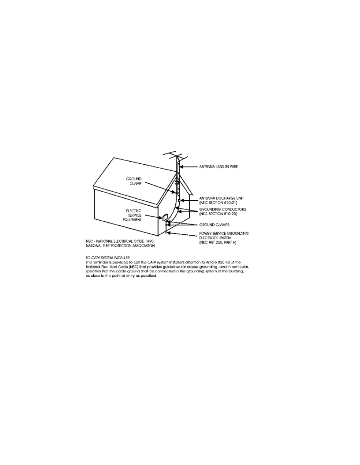
14 Outdoor Antenna Grounding – If an outside antenna or cable system is
connected to the product, be sure the antenna or cable system is grounded so as
to provide some protection against voltage surges and built-up static charges.
Article 810 of the National Electrical Code, ANSI/NFPA 70, provides
information with regard to proper grounding of the mast and supporting
structure, grounding of the lead-in wire to an antenna discharge unit, size of
grounding conductors, location of antenna-discharge unit, connection to
grounding electrodes, and requirements for the grounding electrode.
15 Lightning – For added protection for this product during a lightning storm, or
when it is left unattended and unused for long periods of time, unplug it from
the wall outlet and disconnect the antenna or cable system. This will prevent
damage to the product due to lightning and power-line surges.
16 Power Lines – An outside antenna system should not be located in the vicinity of
overhead power lines or other electric light or power circuits, or where it can fall
into such power lines or circuits. When installing an outside antenna system,
extreme care should be taken to keep from touching such power lines or circuits
as contact with them might be fatal.
17 Overloading – Do not overload wall outlets, extension cords, or integral
convenience receptacles as this can result in a risk of fire or electric shock.
18 Object and Liquid Entry – Never push objects of any kind into this product
through openings as they may touch dangerous voltage points or short-out parts
that could result in a fire or electric shock. Never spill liquid of any kind on the
product.
Page 10

Safety Precautions
x OL-31980-01
19 Servicing – Do not attempt to service this product yourself as opening or
You will find this symbol on the product and/or in the literature that
accompanies this product.
It indicates important operating or maintenance instructions.
removing covers may expose you to dangerous voltage or other hazards. Refer
all servicing to qualified service personnel.
20 Damage Requiring Service – Unplug this product from the wall outlet and refer
servicing to qualified service personnel under the following conditions:
a When the power-supply cord or plug is damaged,
b If liquid has been spilled, or objects have fallen into the product,
c If the product has been exposed to rain or water,
d If the product does not operate normally by following the operating
instructions. Adjust only those controls that are covered by the operating
instructions as an improper adjustment of other controls may result in
damage and will often require extensive work by a qualified technician to
restore the product to its normal operation,
e If the product has been dropped or damaged in any way, and
f When the product exhibits a distinct change in performance – this indicates a
need for service.
21 Replacement Parts – When replacement parts are required, be sure the service
technician has used replacement parts specified by the manufacturer or have the
same characteristics as the original part. Unauthorized substitutions may result
in fire, electric shock, or other hazards.
22 Safety Check – Upon completion of any service or repairs to this product, ask the
service technician to perform safety checks to determine that the product is in
proper operating condition.
23 Wall or Ceiling Mounting – The product should be mounted to a wall or ceiling
only as recommended by the manufacturer.
24 Heat – The product should be situated away from heat sources such as radiators,
heat registers, stoves, or other products (including amplifiers) that produce heat.
Protect yourself from electric shock and your system from damage!
This product complies with international safety and design standards. Observe
all safety procedures that appear throughout this guide, and the safety symbols
that are affixed to this product.
If circumstances impair the safe operation of this product, stop operation and
secure this product against further operation.
Avoid personal injury and product damage! Do not proceed beyond any symbol
until you fully understand the indicated conditions!
Page 11

Safety Precautions
OL-31980-01 xi
You may find this symbol on the product and/or in the literature that
accompanies this product.
It indicates a live terminal; the symbol pointing to the terminal device.
You may find this symbol on the product and/or in the literature that
accompanies this product.
It indicates a protective earth terminal.
You may find this symbol on the product and/or in the literature that
accompanies this product.
It indicates excessive or dangerous heat.
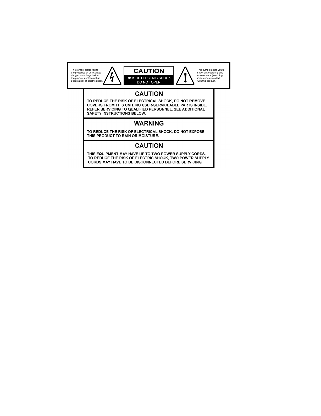
Power
Important! This is a Class I product. You must earth this product. This
equipment may have up to two power supply cords. To reduce the risk of
electric shock, two power supply cords may have to be disconnected before
servicing.
This product plugs into a socket-outlet. The socket-outlet must be near this
product, and must be easily accessible.
Connect this product only to the power source that is indicated on the rear panel
of this product.
If this product does not have a mains power switch, the power cord serves this
purpose
Enclosure
Do not allow moisture to enter this product.
Do not open the enclosure of this product unless otherwise specified.
Do not push objects through openings in the enclosure of this product.
Cables
Always disconnect all power cables before servicing this product.
Always pull on the plug or the connector to disconnect a cable. Never pull on the
cable itself.
Do not walk on or place stress on cables or plugs.
Factory service
Refer service only to service personnel who are authorized by the factory.
Page 12

Safety Precautions
x ii OL-31980-01
Règles de sécurité
Ce symbole figure dans la documentation accompagnant ce produit. Il indique
d'importantes instructions de fonctionnement ou d'entretien.
Ce symbole peut être attaché à ce produit. Il indique une borne sous tension;
la direction indique la borne.
Ce symbole peut être attaché à ce produit. Il indique une borne de terre de
protection.
Ce symbole peut être attaché à ce produit. Il indique une température
excessive ou dangereuse.
Protégez-vous des risques d'électrocution et protégez votre système contre les
endommagements éventuels.
Ce produit respecte les standards internationaux de sécurité et de conception.
Veuillez observer toutes les procédures de sécurité qui apparaissent dans ce guide,
ainsi que les symboles de sécurité qui figurent sur le produit.
Si, du fait des circonstances, ce produit cesse de fonctionner normalement, cessez de
l'utiliser et empêchez-en l'utilisation future.
Évitez le risque de blessures et de dommages aux produits! Ne procédez à aucune
tâche tant que vous n'aurez pas entièrement assimilé les conditions indiquées par un
symbole!
Alim entation
Important! Ce produit fait partie de la classe I. Vous devez le mettre à la terre.
Ce produit se branche dans une prise murale. Cette dernière doit être placée à
proximité du produit et doit être facilement accessible.
Ne branchez ce produit qu'à la source d'alimentation indiquée sur son panneau
arrière.
Si ce produit n'a pas d'interrupteur d'alimentation générale, le cordon
d'alimentation remplit ce rôle.
Enceinte
Ne laissez pas l'humidité pénétrer dans ce produit.
N'ouvrez pas l'enceinte de ce produit, sauf instructions contraires.
Ne forcez pas d'objets dans les ouvertures du boîtier.
Câbles
Débranchez toujours tous les cordons d'alimentation avant de réparer ce produit.
Tirez toujours sur la prise ou le connecteur pour débrancher un câble. Ne tirez
jamais directement sur le câble.
Page 13

Safety Precautions
OL-31980-01 x iii
Ne marchez pas sur les câbles ou les prises et n'y exercez aucune pression.
Dieses Symbol erscheint auf dem Gerät und/oder in der ihm beiliegenden
Literatur. Es bedeutet wichtige, zu beachtende Betriebs-oder
Wartungsanweisungen.
Wenn dieses Zeichen am Gerät angebracht ist, warnt es vor einer
spannungsführenden Stelle.
Dieses Symbol kennzeichnet auf dem Ger ät die Anschlußstelle der
Sicherheitserde.
Wenn dieses Zeichen am Gerät angebracht ist, warnt es vor heißen Stellen, die
zu Verbrennungen führen können.
Réparations effectuées à l'usine
Ne confiez les travaux de réparations qu'au personnel autorisé par l'usine.
Sicherheitsvorkehrungen
Schützen Sie sich gegen elektrischen Schlag, und Ihr Gerät gegen Beschädigung!
Dieses Gerät entspricht internationalen Sicherheits-und Ausführungsnormen.
Beachten Sie alle in diesem Handbuch enthaltenen Sicherheitshinweise sowie die
am Gerät angebrachten Warnzeichen.
Sollten örtliche Umstände den sicheren Betrieb dieses Gerätes beeinträchtigen,
schalten Sie es ab und sichern es gegen weitere Benutzung.
Vermeiden Sie Verletzungen sowie Beschädigung des Gerätes! Wenn Sie zu einem
der folgenden Warnzeichen gelangen, nicht weiterarbeiten, bis Sie seine Bedeutung
voll verstanden haben!
Netzspannung
Wichtig! Dieses Gerät ist ein Produkt der Schutzklasse I. Es muß geerdet werden.
Das Gerät ist an einer Steckdose anzuschließen. Diese muß sich leicht zugänglich
in unmittelbarer Nähe des Gerätes befinden.
Die Netzversorgung muß den auf der Rückwand des Gerätes angegebenen
Werten entsprechen.
Falls sich kein Hauptschalter am Gerät befindet, dient das Netzkabel diesem
Zweck.
Gehäuse
Das Innere des Gerätes ist vor Feuchtigkeit zu schützen.
Das Gehäuse ist nicht zu öffnen.
Niemals einen Gegenstand durch die Gehäuseöffnungen einführen!
Page 14

Safety Precautions
x iv OL-31980-01
Kabel
Encontrará este símbolo en el impreso que acompaña a este producto. Este símbolo
indica instrucciones importantes de funcionamiento o m antenimiento.
Es posible que este símbolo esté pegado al producto. Este símbolo indica un
terminal vivo, la flecha apunta hacia el aparato terminal.
Podría encontrar este símbolo pegado al producto. Este símbolo indica un terminal
de protección de tierra.
Podría encontrar este símbolo pegado al producto. Este símbolo indica calor
excesivo o peligroso.
Vor jeglicher Wartung des Gerätes sind alle Kabel zu entfernen.
Hierzu grundsätzlich am Stecker oder Verbindungsstück und niemals am Kabel
selber ziehen.
Nicht auf die Kabel oder Stecker treten oder diese einer Zugbelastung aussetzen.
Hersteller-Wartung
Wartungsarbeiten sind nur durch vom Hersteller autorisierte Techniker
vorzunehmen.
Precauciones de seguridad
¡Protéjase contra la electrocución y proteja su sistema contra los daños!
Este producto cumple con los criterios internacionales de seguridad y diseño.
Observe todas los procedimientos de seguridad que aparecen en esta guía, y los
símbolos de seguridad adheridos a este producto.
Si las circunstancias impiden la operación segura de este producto, suspenda la
operación y asegure este producto para que no siga funcionando.
¡Evite lastimarse y evite dañar el producto! No avance más allá de cualquier símbolo
hasta comprender completamente las condiciones indicadas!
Alim entación
Importante! Este es un producto de Clase I. Tiene que estar conectado a tierra.
Este producto se conecta a un enchufe. El enchufe necesita estar cerca del
producto y ser fácilmente accesible.
Conecte este producto únicamente a la fuente de suministro eléctrico indicada en
el panel posterior del producto.
Si el producto no tiene interruptor para la linea principal, utilice el cordón to ma
de corriente para este propósito.
Page 15

Safety Precautions
OL-31980-01 xv
Cubierta
Questo simbolo, che appare nella letteratura di accompagna mento del
prodotto, indica importanti istr uzioni d'uso e di manutenzione.
Sul prodotto potete vedere questo simbolo che indica un dispositivo terminale
sotto tensione; la freccia punta verso il dispositivo.
Potrete trovare il presente simbolo applicato a questo prodotto. Questo
simbolo indica un terminale protettivo di messa a ter ra.
Potrete trovare il presente simbolo attaccato a questo prodotto. Questo
simbolo indica un calore eccessivo o pericoloso.
No permita que la humedad penetre en este producto.
No abra la cubierta del producto a menos que se indique lo contrario.
No introduzca objetos a través de las aberturas de la cubierta del producto.
Cables
Siempre desconectar todos los cables eléctricos antes de revisar o reparar el
producto.
Tire siempre del enchufe o del conector para desconectar un cable. Nunca tire del
cable mismo.
No camine ni aplique presión sobre los cables o enchufes..
Revisión y reparación de fábrica
Solo personal aprobado por la fábrica puede darle servicio al producto.
Precauzioni di sicurezza
Proteggetevi da scosse elettriche e proteggete il vostro sistema da possibili danni!
Questo prodotto soddisfa le norme internazionali per la sicurezza ed il design.
Seguite tutte le procedure di sicurezza contenute in questa guida e i simboli di
sicurezza applicati al prodotto.
Se circostanze avverse compromettono la sicurezza d'uso di questo prodotto,
interrompetene l'uso e assicuratevi che il prodotto non venga più utilizzato.
Evitare infortuni alla persona e danni al prodotto! Non procedere oltre a qualunque
simbolo fino a quando non si siano comprese pienamente le condizioni indicate!
Alim entazione
Importante! Questo prodotto è di Classe I. Va messo a terra.
Questo prodotto si inserisce in una presa di corrente. La presa di corrente deve
essere in prossimità del prodotto, e deve essere facilmente accessibile.
Page 16

Safety Precautions
x vi OL-31980-01
Collegare questo prodotto solamente alla fonte di alimentazione indicata sul
pannello posteriore di questo prodotto.
Se questo prodotto non è dotato di un interruttore principale, il cavo di
alimentazione funge a questo scopo.
Chiusura
Proteggete da umidità questo prodotto.
Non aprire la chiusura di questo prodotto a meno che non sia specificato
diversamente. Non inserire oggetti attraverso le fessure della chiusura.
Cavi
Staccare sempre tutti i cavi di alimentazione prima di svolgere l'assistenza
tecnica al prodotto.
Per scollegare un cavo tirate la spina o il connettore, non tirare mai il cavo stesso.
Non calpestare o sottoporre a sollecitazioni i cavi o le prese.
Riparazionoi di fabbrica
Per le riparazioni contattate solamente personale tecnico autoizzato dalla
fabbrica.
Page 17

Contents
Safety Precautions vii
About This Manual xxiii
Objective............................................................................................................. xxiii
Audience ............................................................................................................ xxiii
Required Knowledge......................................................................................... xxiii
Chapter 1 Introduction 1
D9859 Advanced Receiver Transcoder .............................................................................. 2
Digital Program Distribution................................................................................. 2
Key Features............................................................................................................ 2
Software Update ..................................................................................................... 3
Transport Stream Outputs.................................................................................................. 4
DVB-ASI Outputs ................................................................................................... 4
MPEGoIP Output ................................................................................................... 4
MPE Output ............................................................................................................ 5
Disaster Recovery................................................................................................................ 6
Chapter 2 Quick Setup - Read Me First! 9
Maintenance of EMC Compliance ................................................................................... 10
Connecting the Transcod er to Other Equipment ............................................................ 11
Setting up for Network Connection................................................................................. 12
Quick Setup Instructions for RF Acquisition .................................................................. 13
Assigning a Program Channel to a PE (Program E ntry) ................................................ 15
Setting up the ASI Output ................................................................................................ 16
Setting the DP M Mode...................................................................................................... 17
Chapter 3 Installation 19
Power Connection ............................................................................................................. 20
Installing the D9859 Transcoder....................................................................................... 21
Rack Mounted....................................................................................................... 21
Cooling .................................................................................................................. 21
Grounding ............................................................................................................. 21
Mounting the D9859 Transcoder to a Rack ......................................................... 21
Connecting the AC Power to the D9859 Transcoder ......................................... 22
Page 18

x viii OL-31980-01
Rear Connector Panel........................................................................................................ 23
Connecting the Input/Output Signals............................................................................. 25
Connecting the RF Inputs .................................................................................... 25
Connecting the ASI Input .................................................................................... 25
Connecting the Video Outputs ............................................................................ 25
Connecting the Balanced Audio Output............................................................. 25
Connecting the Ethernet Management Interface................................................ 26
Connecting the IP TS Output............................................................................... 26
Connecting the ASI Outputs................................................................................ 27
Connecting an External Alarm System ............................................................... 27
Connecting the RS-232 Data Interface................................................................. 28
Connecting the Cue T one/Cue T rigger Interface .............................................. 28
Configuring Open-collector Outputs .................................................................. 29
Setting Admin User Privileges via a Telnet/SSH Connection ....................................... 30
Administrator User Privileges ............................................................................. 30
Starting a Telnet/SSH Session ............................................................................. 30
Adding a New User.............................................................................................. 31
Deleting a User...................................................................................................... 31
Changing a Username .......................................................................................... 32
Changing a Password (allowed by all Users) ..................................................... 32
Printing the List of Users...................................................................................... 32
Resetting the Login Credentials .......................................................................... 32
Chapter 4 Front Panel Operation 33
About the Front Panel ....................................................................................................... 34
LCD........................................................................................................................ 34
Keypad .................................................................................................................. 34
Front Panel LEDs .................................................................................................. 34
Navigation/S election Keypad ............................................................................. 35
Locking/Unlocking the Front Panel ................................................................................ 38
Startup Screen.................................................................................................................... 39
Main Structure ...................................................................................................... 39
Channel Authorization Status ............................................................................. 39
LCD Panel ............................................................................................................. 39
LCD Symbol .......................................................................................................... 40
Assigning Program to the Program Entry .......................................................... 41
Deleting a Program from the Program Entry ..................................................... 42
Main Menu......................................................................................................................... 43
Status Menu ....................................................................................................................... 44
Structure ................................................................................................................ 44
Status Menu - IP.................................................................................................... 52
Status Menu - DR.................................................................................................. 53
Setup Menu ........................................................................................................................ 56
Setup Menu: Admin ............................................................................................. 57
Setup Menu: TS Input........................................................................................... 62
Setup Menu: IP...................................................................................................... 68
Page 19

Setup Menu: Services ........................................................................................... 76
Setup Menu: Outputs ........................................................................................... 88
Setup Menu: CA ................................................................................................. 115
Setup Menu: Alarm/Wa rning ........................................................................... 117
Setup Menu: Noise Cutoffs ................................................................................ 119
Setup Menu: DR.................................................................................................. 121
About Menu..................................................................................................................... 124
General ................................................................................................................ 124
Licenses ............................................................................................................... 125
Versions Menu................................................................................................................. 126
Main Versions ..................................................................................................... 126
Transcoder Softwa re Versions ........................................................................... 128
Transcoder Hardware Versions......................................................................... 128
Diagnostics Menu............................................................................................................ 129
Alarms/Warnings .............................................................................................. 129
Logs...................................................................................................................... 129
PSI - Frequency Plan........................................................................................... 130
PSI - Channels ..................................................................................................... 130
PSI - Tables .......................................................................................................... 131
Power On............................................................................................................. 131
Health Monitor ................................................................................................... 132
Chapter 5 Web GUI Setup and Monitoring 133
Logging On to the Web GUI ........................................................................................... 134
D9859 Summary Overview ............................................................................................ 135
Shortcuts .............................................................................................................. 135
Modules............................................................................................................... 136
Alarms/Warnings .............................................................................................. 137
D9859 Menus ................................................................................................................... 138
D9859 Web GUI Environment........................................................................................ 140
Window Buttons ................................................................................................. 140
Setting up Input Information ......................................................................................... 141
Setting up the RF Input ...................................................................................... 141
Setting up the ASI Input..................................................................................... 146
Setting up SI Receive Parameters ...................................................................... 148
Setting up Muting Threshold Controls ............................................................. 151
Viewing the Input Status.................................................................................... 153
Configuring t he Disaster Recovery Settings ..................................................... 154
Viewing the Disaster Recovery Status .............................................................. 157
Setting up the Channel Selections ..................................................................... 159
Viewing the Channel Status............................................................................... 160
Viewing the CA Status ....................................................................................... 162
Setting up the BISS Mode................................................................................... 163
Viewing the PSI Tables....................................................................................... 164
Viewing PSI Frequency Information................................................................. 165
Viewing the PSI Channels.................................................................................. 166
Page 20

xx OL-31980-01
Viewing the PID Input Status ............................................................................ 167
Setting up Audio and Video Information...................................................................... 168
Setting up the Video Parameters ....................................................................... 168
Setting up Captions ............................................................................................ 170
Setting up Subtitles............................................................................................. 171
Setting up VBI ..................................................................................................... 173
Setting up Audio Param eters............................................................................. 174
Setting up Cueing Parameters ........................................................................... 177
Setting up Cue Tone Test ................................................................................... 179
Setting up Cue Tones.......................................................................................... 180
Setting up Services .............................................................................................. 181
Configuring Transport Stream Information.................................................................. 182
Configuring t he ASI Output .............................................................................. 182
Configuring t he DP M ASI Details ..................................................................... 188
Viewing the ASI Output Transport Status........................................................ 194
Configuring t he MPEGoIP Output.................................................................... 195
Configuring t he DPM MPEGoIP Output Details ............................................. 203
Viewing the MPEG Output Transport Status................................................... 210
Typical set up for Digital Program Mapping (DPM) ....................................... 210
Setting up Default Settings for the Transcoder ................................................ 213
Configuring System Settings .......................................................................................... 218
Viewing the System Identification .................................................................... 218
Viewing Hardware Features and Base License Information ........................... 219
Setting up IP Information................................................................................... 220
Setting up IP Routing Information .................................................................... 224
Configuring t he MPE Settings ........................................................................... 226
Setting up SNMP I nformation and Trap Destinations .................................... 228
Configuring Time/Clock S ettings ..................................................................... 230
Viewing the Alarm/Warning Status................................................................. 231
Setting up Alarms a nd Warnings ...................................................................... 232
Viewing Alarm/ Warning History .................................................................... 235
Viewing Version I nformation ............................................................................ 236
Viewing Transcoder Version Information ........................................................ 239
Setting up Import/Export File Information ..................................................... 241
Setting up Import/Export FTP Information ..................................................... 243
Managing D9859 Web GUI Accounts ............................................................... 245
Configuring Lock Level Settings ....................................................................... 249
Configuring Front Panel Settings ...................................................................... 251
Viewing Support Information ........................................................................................ 252
Viewing Contact Information ............................................................................ 252
Viewing Diagnostic Logs ................................................................................... 253
Viewing the Usage Cou nters ............................................................................. 254
Viewing Operating Fan Speeds and Board T emperatures .............................. 255
Viewing Alarm/ Warning History .................................................................... 256
Loading a Software Version and L icense.......................................................... 257
Page 21

Chapter 6 Service and Maintenance 259
D9859 Transcoder Alarm Messages............................................................................... 260
Alarms ................................................................................................................. 260
Warnings ............................................................................................................. 299
Power Supply Replacement............................................................................................ 317
Chapter 7 Customer Information 319
Appendix A Technical Specifications 321
L-Band Input and Processing ......................................................................................... 322
General ................................................................................................................ 322
LNB LO Stability................................................................................................. 322
LNB Power and Control..................................................................................... 323
DVB-S/DVB-S2................................................................................................... 323
Video Inputs/Outputs and Processing.......................................................................... 326
General ................................................................................................................ 326
Video Inputs........................................................................................................ 326
Video Outputs..................................................................................................... 326
Audio Inputs/Outputs....................................................................................... 329
VBI Data Input/Output ..................................................................................... 330
Transport Stream Outputs.............................................................................................. 331
ASI Output .......................................................................................................... 331
MPEGoIP Output ............................................................................................... 331
MPE Output ........................................................................................................ 331
Control, Management and Data Interfaces ................................................................... 333
Ethernet Management Interface ........................................................................ 333
Ethernet Data Interface....................................................................................... 333
RS-232 Data Interface ......................................................................................... 333
Alarm Interface ................................................................................................... 333
Contact Closure Interface ................................................................................... 334
Power and General Specifications.................................................................................. 335
General ................................................................................................................ 335
Power................................................................................................................... 335
Mechanical .......................................................................................................... 336
Environment ....................................................................................................... 336
Appendix B Default Settings and Lock Levels 337
Factory Default Settings and Lock Levels ..................................................................... 338
Administration.................................................................................................... 338
ASI Input ............................................................................................................. 339
RF Input ............................................................................................................... 339
Tune Mode .......................................................................................................... 340
Disaster Recovery ............................................................................................... 340
Page 22

xxii OL-31980-01
IP .......................................................................................................................... 341
Trap Destinations ............................................................................................... 342
Protocols .............................................................................................................. 342
Video.................................................................................................................... 342
Audio ................................................................................................................... 343
Captions .............................................................................................................. 343
VBI ....................................................................................................................... 343
Subtitles ............................................................................................................... 343
Decode ................................................................................................................. 344
Cueing ................................................................................................................. 344
TS Out - ASI ........................................................................................................ 345
TS Out - MOIP .................................................................................................... 345
DPM - ASI/MOIP ............................................................................................... 346
Transcode ............................................................................................................ 347
Inband.................................................................................................................. 348
Options ................................................................................................................ 348
Alarm/Warning.................................................................................................. 349
Noise Cutoff ........................................................................................................ 349
Import/Export (Web GUI only) ........................................................................ 350
DPM Default Settings for Different Output Modes...................................................... 351
Appendix C Compliance 355
Applicable Standards and Notices ................................................................................. 356
Safety ................................................................................................................... 356
ESD ...................................................................................................................... 356
Electromagnetic Compatibility Regulatory Requirements .............................. 356
FCC Notices ........................................................................................................ 357
Industry Canada Notice ..................................................................................... 357
Unauthorized Modifications.............................................................................. 357
Declaration of Conformity.............................................................................................. 358
Index 361
Page 23

About This Manual
OL-31980-01 x x iii
About This Manual
Objective
This manual describes how to install, use and maintain the Cisco D9859 Advanced
Receiver Transcoder.
Note: The manual describes all available options for the D9859 transcoder. Your
D9859 transcoder may only have some of the features described in this manual.
Audience
The audience of this manual includes users (operators) and service personnel who
are responsible for the installation, configuration, operation, monitoring and service
of the D9859 transcoder.
Required Knowledge
To use this documentation, the user should have a basic knowledge of the
technology used in relation to this product. Service personnel should have
additional skills and be familiar with cabling, electronic circuitry, and wiring
practices.
This manual is intended for operators who are responsible for the configuration,
remote operation and maintenance of the D9859 transcoder.
Page 24

Page 25

OL-31980-01 1
Overview
This chapter is a general introduction to the Cisco D985 9 Advanced
Receiver Transcoder. It describes the most common applications and
interfaces of the transcoder.
1 Chapter 1
Introduction
In This Chapter
D9859 Advanced Receiver Transcoder ...............................................2
Transport Stream Outputs...................................................................4
Disaster Recovery.................................................................................6
Page 26

Chapter 1 Intr oduction
2 OL-31980-01
D9859 Advanced Receiver Transcoder
The Cisco D9859 Advanced Receiver Transcoder extends the distribution options for
MPEG-4 Advanced Video Coding (AVC) high definition from solely MPEG-4
environments to existing MPEG-2 networks. Support for up to eight simultaneous
high-definition or standard-definition (SD) channels of decryption and transcoding
provides the advantage of density for locations requiring more than just a single
channel. The D9859 can provide up to 8 down-converted MPEG-2 standard
definition programs or MPEG-2 high-definition transcoded programs. Video and
two audio outputs are available for analog down-conversion for one of the
decrypted incoming MPEG-4 high-definition programs.
Digital Program Distribution
The Asynchronous Serial Interface (ASI) and MPEG over IP (MPEGoIP) transport
outputs are individually configurable and provide the capability of carrying up to
eight decrypted transcoded programs for digital tier distribution. This helps the
compressed video programs to be efficiently distributed to subscribers equipped
with digital set-top boxes. Digital audio passthrough is synchronized to the
transcoded program output. Compliant program-specific information and service
information (PSI/SI) regeneration provides integration into a digital tier distribution
network for eight transcoded programs.
Key Features
The D9859 Advanced Receiver Transcoder provides the following key features:
Four L-Band inputs
DVB-S Demodulation for QPSK
DVB-S2 Demodulation for QPSK and 8PSK
Cisco PowerVu
descrambling
Supports Basic Interoperable Scrambling System (BISS) conditional access
Decryption and transcoding of up to eight programs for digital transport output
Two digital transport outputs available (ASI and MPEGoIP)
Support for up to eight simultaneous high-definition or standard-definition
channels of decryption and transcoding and passthrough of the original channel.
Total of 16 regenerated outputs (8 transcode + 8 passthrough)
Program transcoding to support down-conversion of a MPEG-4 HD program to
a MPEG-2 SD program
®
conditional access with Data Encryption Standard (DES) or DVB
Page 27

D9859 Advanced Receiver Transcoder
OL-31980-01 3
PSI/SI regeneration support on all licensed outputs (up to eight programs
transcoded + up to 8 original content pass through)
4:2:0 high-definition 1080i and 720p video decoding
AFD support for down-conversion of a decoded HD program with aspect ratio
conversion
Dolby Digital (AC-3) and Dolby Digital Plus (E-AC-3) audio decoding
Closed captioning passthrough of EIA-608 and EIA-708 for transcoded programs
Audio passthrough synchronization for transcoded programs
Additional ASI outputs for redundancy
MPEGoIP output for network connectivity
DVB subtitle passthrough with transcode programs
Contact closure terminals for simple alarm monitoring
Simple Network Management Protocol (SNMP) for setup, control, and
monitoring
Field-upgradeable software
Field-upgradable additional transcoder channel licenses
Front panel LCD for control and monitoring
Web browser interface for easy setup, control, and monitoring
Uplink addressable decoder output control (vertical blanking interval [VBI],
audio routing, DPI, and ASI output)
Dual-tone multifrequency (DTMF) cue tone and cue trigger outputs for ad
insertion
Digital Program Mapping that provides uplink control for service replacements
in blackout areas
Advanced Disaster Recovery capabilities
Software Update
All software in the D9859 transcoder is stored in non-volatile memory that can be
electrically programmed. New software releases for the D9859 transcoder can be
downloaded via the Ethernet 10/100/1000BASE-T Management interface.
Page 28
Chapter 1 Intr oduction
4 OL-31980-01
Transport Stream Outputs
DVB-ASI Outputs
The D9859 transcoder has three DVB-ASI outputs. These outputs can be used as
inputs for multiplexers, groomers or other types of DVB-ASI reception equipment.
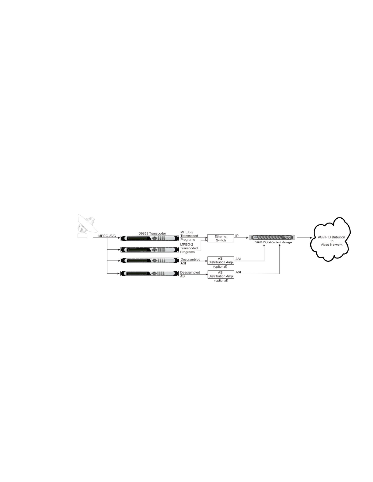
MPEGoIP Output
The MPEGoIP output provides a number of output modes including the capability
of carrying a decrypted program for digital tier distribution. This helps ensure that
compressed video programs are efficiently distributed to households equipped with
digital set-top boxes. Digital Program Insertion (DPI) information will also be
available along with the video and audio PIDs (Packet Identifiers) for external adinsertion in compressed digital format.
The diagram below shows an example of the D9859 transcoder used in an ASI or
MPEGoIP application.
Page 29
Transport Stream Outputs
OL-31980-01 5
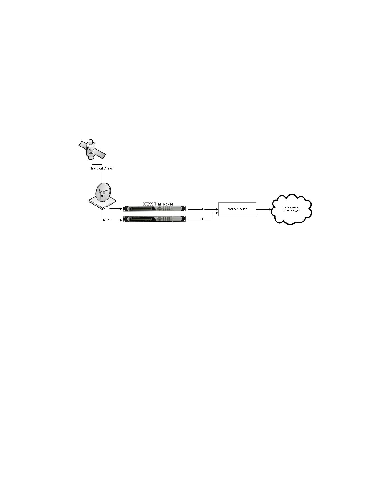
MPE Output
The Multiprotocol Encapsulation (MPE) output provides a means to carry packet
oriented IP protocols on top of a transport stream. The MPE output receives IP
packets from the transport stream and the IP data can be sent through an Ethernet
switch to an IP router or directly to a receiving device.
The diagram below shows an example of the D9859 transcoder used in an MPE
application.
Page 30

Chapter 1 Intr oduction
6 OL-31980-01
Disaster Recovery
Program
Entry
Origin Transport
Channel Number
Backup 1
Transport
Channel
Number
Backup 2
Transport
Channel
Number
Backup 3
Transport
Channel
Number
PE1
101
11
101
801
PE2 2 12 1005
In the event of a transmission failure on the primary feed, the disaster recovery
allows for continued programming, with limited to no downtime. The failure
condition could be triggered by one of the following events:
RF Lock Loss
Unstable RF signal
Transport Loss (RF locked, but no transport stream packets and NULL packets
received)
Once the receiver detects a failure after the configured timeout, it will initiate a
disaster recovery search based on the search path determined by the disaster
recovery configuration. A DR symbol is displayed on the front panel, and the D9859
web GUI displays a D/R in progress status. During a disaster, the receiver will
attempt to tune to a different backup transport, based on the search path configured.
The origin transport consists of origin transport tuning parameters and PE service
IDs, configured in the Input menus. For more information on the Input parameters,
see RF1, RF2, RF3, RF4 (RFx) Input (on page 63) for the front panel, and Setting up
the RF Input (on page 141) for the web GUI.
Note: If you perform a master PE channel change during a disaster recovery search,
the search will end, the current tuning parameters will be locked, and the current
channel will become the origin channel. If you perform a tuning change during a
disaster recovery search, the search will end, the current user tuning parameters will
become the origin tuning parameters, and the origin may be updated by any of the
NIT updates that follow.
For example, the disaster recovery is configured as follows:
When disaster occurs, the receiver will tune to channel 11, as defined on the Backup
1 transport.
If the acquisition is successful on the Backup 1 transport (PAT is received), the
receiver will set PE 1 to channel 11 and PE2 to channel 12 and declare that the
disaster is over.
Page 31

Disaster Recover y
OL-31980 -01 7
If the acquisition fails or there is no signal lock on the Backup 1 transport, the
receiver will continue to search for the next backup transport for PE1 (Backup 2
transport). If the acquisition is successful on the Backup 2 transport, the receiver will
set PE1 to channel 101, but leave PE2 to channel 2 because PE2 is not specified for
Backup 2 transport.
If the acquisition fails or there is no signal lock on the Backup 2 transport, it will
continue the search path and set PE1 to channel 801 and PE2 to channel 1005 if the
acquisition is successful on the Backup 3 transport. However, if the acquisition fails
or there is no signal lock on the Backup 3 transport, the search path will continue to
the origin transport. The search path will cycle through origin, Backup 1, Backup 2,
and Backup 3 infinitely.
The search path is shown in the Disaster Recovery Status information on the front
panel and web GUI.
By default, the disaster recovery is enabled. To set up and view the disaster recovery
parameters using the front panel, see Setup Menu: DR (on page 121) and Status
Menu - DR (on page 53). To set up and view the disaster recovery parameters using
the web GUI, see Configuring the Disaster Recovery Settings (on page 154) and
Viewing the Disaster Recovery Status (on page 157).
Page 32

Page 33

OL-31980-01 9
Overview
This chapter provides a quick setup for the Cisco D9859 Advanced
Receiver Transcoder. If you are unsure about which receiver settings
to use, contact your local service provider for assistance.
2 Chapter 2
Quick Setup - Read Me First!
In This Chapter
Maintenance of EMC Comp liance ....................................................10
Connecting the Transcoder to Other Equipment.............................11
Setting up for Network Connection..................................................12
Quick Setup Instructions for RF Acquisition ...................................13
Assigning a Program Channel to a PE (Program E ntry) .................15
Setting up the ASI Output .................................................................16
Setting the DPM Mode.......................................................................17
Page 34

Chapter 2 Quick Setup - Read Me First!
10 OL-31980-01
Maintenance of EMC Compliance
Double-shielded (braid/foil or braid/braid) cables should be used for all ASI I/O
and RF inputs. Single-shield cables are acceptable for all other inputs and outputs.
For terminal block (Alarms) I/O, no shielding is required.
Page 35

Connecting the Transcoder to Other Equipment
OL-31980-01 11
Connecting the Transcoder to Other Equipment
The following displays the rear panel of the D9859 transcoder:
1 Connect the L-Band signal to RF1. 13V or 18V LNB power is only available on
the RF1 port. The factory default setting for LNB power is OFF.
2 Connect the ASI OUT port to an ASI device for digital tier applications.
Note: A double-shielded coaxial cable is required to connect to the ASI OUT
and/or the ASI IN port in order to meet EMC requirements.
3 Connect the Composite Video Outputs to a video monitor.
4 Using a multi-conductor, pluggable cable, connect the balanced audio outputs,
terminal blocks AUDIO 1 and AUDIO 2 to monitoring equipment.
5 Apply power by connecting the transcoder to a power outlet. The message
“Application Starting” will appear on the front panel. The boot-up process will
take approximately 1 minute for the unit to initialize. When ready, the front
panel display shows the start-up screen.
The power cord (consisting of appliance coupler, flexible cord, and plug)
supplied with this product meets the requirements for use in the country for
which this product was purchased. In general, the power cord must be approved
by an acceptable, accredited agency responsible for evaluation in the country
where the product will be used.
Page 36

Chapter 2 Quick Setup - Read Me First!
12 OL-31980-01
Setting up for Network Connection
1 Press MENU to display the Main menu.
2 If the Advanced Receiver Transcoder is to be connected to a network, press to
move to the Setup menu. Press SELECT. Press twice to select the IP menu.
Press SELECT twice to go to the IP menu.
3 Use the arrow keys to navigate up and down the IP menu, and the arrow
keys to move across the IP menu to set the IP Address, Mask and Gateway
parameters. Use the number keys to directly enter numbers in the fields. For
more information on keypad operation, see Keypad (on page 34).
4 Press SELECT each time to save the changes. Press MENU four times to return
to the startup screen.
Page 37

Quick Setup Instr uctions for RF Acquisition
OL-31980-01 13
Quick Setup Instructions for RF Acquisition
1 Press MENU to display the Main menu.
2 Press to go to the Setup menu. Press SELECT. Press to move to the TS Input
menu. Press SELECT.
3 To setup the ASI input port, go to step 4. To setup the RF1 input port, go to step
5.
4 Press SELECT three times. Press to set the ASI port to Act (Activate). Press
SELECT. Go to step 11.
5 Press SELECT. Press to go to RF1. Press SELECT twice. Use to set the RF1
port parameter to Act (Activate). Press SELECT.
6 Press to move to the LO1, LO2, Crossover menu. Verify these parameters for
your application. If no change is needed, go to Step 7. If required, you may
modify these settings. Use to move to the parameter that you want to modify.
Press SELECT. Use the numerical keypad to enter new frequencies. Press
SELECT.
7 Press five times to move to the Modulation and Rolloff menu. Press SELECT.
Use to choose DVB-S or DVB-S2. Press SELECT. If DVB-S2 is used, press to
choose Rolloff. Press SELECT. Use to choose the value. Press SELECT.
8 Press to move to the Freq., Sym Rate, and FEC menu. Press SELECT. Enter the
RF frequency. Press SELECT. Press to move to the Sym. Rate menu. Press
SELECT. Enter the symbol rate. Press SELECT. If DVB-S2 is used, proceed to
step 9. If DVB-S is used, press to set up the FEC. Press SELECT. Use to
select AUTO. Press SELECT.
9 Press twice to move to the Net ID menu. Press to choose Net ID. Press
SELECT. Enter the value. Press SELECT.
10 Press . Press SELECT. Use to change the LNB power, if needed. Only the
RF1 port is capable of providing 13V or 18V. Press SELECT.
11 Press MENU three times. Press to move to Save & Exit. Press SELECT. Save &
Exit will return you to the Main: Setup menu; Abandon & Exit will go back to the
last menu accessed with the original parameters; Cancel will go back to the last
menu accessed with changes saved.
12 The transcoder will search for the signal and display “Acquisition Successful." It
will find the first available channel on the network. Press MENU twice to return
to the start-up menu.
Page 38

Chapter 2 Quick Setup - Read Me First!
14 OL-31980-01
13 If the front LED is solid green, the unit is authorized. Proceed with Assigning a
Program Channel to a PE (Program Entry) (on page 15)). If the front LED is
flashing green, the unit is unauthorized. Please contact your service provider and
provide the Tracking ID number for authorization. The Tracking ID can be found
on the ABOUT menu. To locate the Tracking ID, press MENU, press twice, and
then press SELECT twice. Make a note of the Tracking ID number. Press MENU
three times to return to the startup screen.
Page 39

Assigning a Program Channel to a PE (Program Entry)
OL-31980-01 15
Assigning a Program Channel to a PE (Program
s
PE1 1 Channel Name
RF1 Freq:12.658 Lvl:<-50 Marg:11.6
PE Ch #
Entry)
1 At the start-up screen, PE1 is initially displayed.
2 Press ADV and use the keys to scroll through the available program entries.
Note: The D9859 is available in an eight channel configuration.
3 Press ADV again to select the channel number.
4 Use the keys to scroll through the available program channels or directly
enter the channel number using the 0 to 9 keys; press SELECT to save the
channel selection.
Note: Enter 0 to remove the program channel from the Program Entry.
5 Repeat steps 2 to 4 to select another authorized program to decode.
Page 40

Chapter 2 Quick Setup - Read Me First!
16 OL-31980-01
Setting up the ASI Output
1 Press MENU to move to the Main Menu.
2 Press to move to the Setup menu. Press SELECT.
3 Press to move to the Outputs menu. Press SELECT.
4 Press to move to the TS Out menu. Press SELECT.
5 Press SELECT to access the ASI menu. Press . Press SELECT. Use to select
the output mode. The factory default is "No Output". It is recommended to set
the Output Mode to Transcoding.
6 Press SELECT. Press to select "YES" if requested to "RESYNC ALL?". Press
SELECT.
7 Press to move to Descramble Mode menu. Press SELECT. Use to select the
scrambling mode. Press SELECT.
8 Press to move to Insert Null Packet. Press SELECT. Use to change the
mode to Yes. Press SELECT.
9 Press APPLY. Press SELECT.
10 Press MENU five times to return to the startup menu.
Page 41

Setting the DPM Mode
OL-31980-01 17
Setting the DPM Mode
LCD Setting
Description
Drop
Removes the service and its associated PMT reference
from the transport output.
Pass
Permits the source content and PMT reference to appear
in the transport output with the same references unless
the source material is mapped on another PE.
Map
Provides the flexibility to define all the outgoing PID
numbers for a PE, including those not currently on
transmission.
Xcode
Provides the flexibility to define all the outgoing PID
numbers for a PE, including those not currently on
transmission, as in Map mode, plus the video PID is
transcoded to output at the rate and settings defined for
the transcode channel.
A program can be set to one of four Digital Program Mapp ing (DPM) modes, either
Drop, Pass, Map, or Xcode. For more information, see TS Out - DPM (on page 99).
1 Press MENU to display the Main Menu.
2 Press to move to the Setup menu. Press SELECT.
3 Press four times to move to the Outputs menu. Press SELECT.
4 Press to move to the TS Out menu. Press SELECT.
5 Press twice to move to the DPM menu. Press SELECT.
6 Press SELECT to access the Global menu.
7 Press SELECT to choose ASI for Resync All. Press and then press SELECT to
continue.
8 Press MENU. Press to move to the ASI menu. Press SELECT. Verify the PE1
”InCh” and ”OutCh” programs.
9 Press three times to choose Act. Press SELECT. Use to select the DPM
mode. Xcode (Transcode) is the most common mode. Press SELECT. Press
APPLY. Press SELECT to save the changes.
10 Press three times to choose PE1. Press SELECT. Use to select PE2. Press
SELECT. Verify the PE2 “InCh” and “OutCh” programs.
11 Press three times to choose Act. Press SELECT. Use to select the DPM
mode. Xcode (Transcode) is the most common mode. Press SELECT. Press
APPLY.
12 Press MENU six times to return to the startup screen.
Page 42

Page 43

OL-31980-01 19
Introduction
This chapter contains the information for technicians installing the
Cisco D9859 Advanced Receiver Transcoder.
Qualified Personnel
Only appropriately qualified and trained service personnel should
attempt to install, operate, or maintain the D9859 transcoder.
WARNING:
Allow only authorized and qualified service personnel to install,
operate, maintain, and service this product. Otherwise, personal
injury or equipment damage may occur.
3 Chapter 3
Installation
In This Chapter
Power Connection ..............................................................................20
Installing the D9859 Transcoder........................................................21
Rear Connector Panel.........................................................................23
Connecting the Input/Output Signals..............................................25
Setting Adm in User Privileges via a Telnet/SSH Connection........30
Page 44

Chapter 3 Instal lation
20 OL-31980-01
Power Connection
WARNING:
Make sure that at least one end of the power cable(s) remains
easily accessible for unplugging, if you need to switch off the unit.
For example, ensure that the socket outlet is installed near the
product.
WARNING:
To avoid electrical shock, connect the three-prong plug on this
product to an earth-grounded three-pin socket outlet only.
To operate the transcoder, you must connect it to an AC power source. For
information about connecting the chassis to AC power, see Appendix A - Technical
Specifications (on page 321).
As Cisco units are designed for continuous operation, some products do not have a
power switch. In this case the mains cord and/or DC power supply cable serve(s) as
the mains disconnect device.
Page 45

Installing the D9859 Tr anscoder
OL-31980-01 21
Installing the D9859 Transcoder
CAUTION:
The inlet air temperature must not exceed 50°C/122°F at any time.
Rack Mounted
The D9859 transcoder is a 1U unit with connector access at the rear panel. The
transcoder is intended for mounting in a standard 19" rack with minimum 1U
spacing between units to allow adequate ventilation/air flow.
The D9859 transcoder is vented from front to back. Multiple units can be stacked in a
rack, provided that adequate cooling is available.
Cooling
The D9859 transcoder is cooled by the use of internal fans. The air intake is from the
front and the air outlet is on the rear.
Note: Adequate cooling must be provided equaling 110 W (maximum) at 25°C per
unit to avoid overheating.
Grounding
You must ensure that the unit is properly connected to ground in order to meet
safety and EMC requirements. Before any other connection is made, the unit must be
connected to a protected ground terminal as described below:
Via the three wire power cord of the AC power supply. This connection is
mandatory.
In addition, via the protective ground terminal on the rear panel of the unit. This
connection provides additional protection of the equipment.
Mounting the D9859 Transcoder to a Rack
1 Mount L-brackets in the rack to support each D9859 transcoder to be installed.
2 Place the transcoder in its position in the rack.
3 Mount the transcoder securely to the rack by securing the mounting flanges to
the rack using the four screws provided.
4 Make sure the air outlet holes on the back of the transcoder are not obstructed to
allow air flow from the front to the back of the chassis.
Page 46

Chapter 3 Instal lation
22 OL-31980-01
Connecting the AC Power to the D9859 Transcoder
1 Connect the power cord (supplied with the D9859 transcoder) between the rear
panel power receptacle and a 100 to 120/200 to 240 V AC power outlet.
2 Make sure that the power cable is connected to protective ground. See for
Grounding (on page 21) more information.
The D9859 transcoder is equipped with one power supply located in the rear of the
chassis. Note the location of the power supply in the event of alarms/warnings
resulting in replacement of a power supply. Alarm messages appear in the Message
Log.
Page 47

Rear Connector Panel
OL-31980-01 23
Rear Connector Panel
Connector
Description
Type
RF Inputs
Each input accepts an LNB signal input.
RF1 provides LNB power for use when no
external LNB power source is available. RF2
to RF4 require an external LNB power
source.
F
Reference Input
For future use.
BNC
ASI Input
Asynchronous Serial Interface Input.
BNC
ASI Outputs
Three Asynchronous Serial Interface
Outputs.
BNC
TS Output (Data)
This is for the MPEGoIP and MPE outputs.
The MPEGoIP output of the transport
stream is encapsulated in the IP packets to a
groomer for distribution. The MPE output
receives IP packets from the transport
stream.
RJ-45
Management
For accessing the web GUI and upgrading
the D9859 software application (code
downloading).
RJ-45
Cue Tone/Cue Trigger
Relay Outputs
Program relay provides programmed
responses for alarms, cue trigger states for
ad-insertion equipment, or a cue tone
output for connection to ad-insertion
equipment.
15-pin sub-D female
RS-232 Data
RS-232 data output: 7 bits, even parity, 1
stop bit, up to 38.4 kbps. These outputs are
user-configurable via the Setup menu on
the front panel
9-pin sub-D female
The following diagram show the rear connector panel of the D9859 transcoder:
The following table describes the function and type of the various connectors.
Page 48

Chapter 3 Instal lation
24 OL-31980-01
Connector
Description
Type
Composite Video
Outputs
CVBS 1 and CVBS 2 provide two identical
SD composite video outputs for monitoring
applications.
BNC
Balanced Audio Outputs
Audio 1 and Audio 2 provide two stereo
pairs or four mono channels.
Terminal Blocks
Ground
Screw
Grounding point for
the transcoder
Power
AC power
IEC 60320 Sheet 14
Page 49

Connecting the Input/Output Signals
OL-31980-01 25
Connecting the Input/Output Signals
Connector
Connector type
Terminal Block
Connecting the RF Inputs
Connect up to four LNB RF cables to the RF connectors labeled RF1 through RF4 on
the rear of the unit.
Use 75-ohm (braid/foil or braid/braid), low insertion loss coaxial cable.
Each input accepts an LNB signal input. RF2 to RF4 require an external LNB power
source.
Connecting the ASI Input
If desired, connect to the ASI IN port to an asynchronous serial interface for uplink
monitoring.
Connecting the Video Outputs
Connector for the Video Output
The video output connectors are of the BNC type.
Connecting the Composite Video Output
Connect a video monitor to the CVSB 1 and CVSB 2 connectors. The two outputs are
identical. Use a 75-ohm double-braided coax cable.
Connecting the Balanced Audio Output
1 Connect the AUDIO 1 and AUDIO 2 balanced audio outputs to monitoring
equipment. Use a multi-conductor, pluggable cable from the transcoder's
AUDIO 1 and AUDIO 2 (Left and Right) terminals to your equipment, as shown
in the following illustration.
Page 50

Chapter 3 Instal lation
26 OL-31980-01
2 Feed the stripped ends of the positive, negative and ground wires into the
appropriate terminals as labeled, and then screw the terminal screws (located on
the top of the terminal block) finger tight to each wire.
Connecting the Ethernet Management Interface
The RJ-45 interface for 10/100/1000BASE-T Ethernet is currently intended for
upgrading/downloading the software application.
Hint: If you experience problems with the 10BASE-T Ethernet it is advised that you
change it to a 100BASE-T connection.
You must set up the IP address, the default gateway and the subnet mask to match
the network connection. This is done through the front panel menu. For more
information, see IP (on page 69).
Proper cables are required for reliable Ethernet operation; to run over a maximum
segment length of 100 m the cable has to comply with the EIA/TIA Category 6 wire
specifications.
1 Connect a crossed RJ-45 cable between the Ethernet connector on the D9859
transcoder and the Ethernet port of your PC.
Note: You need a crossover cable if you want to connect the Ethernet interface of
the D9859 transcoder directly to another Ethernet device without using a hub or
switch.
2 Set up the IP address on the D9859 transcoder (via the front panel display). For
information on setting up the IP address via the front panel, see IP (on page 69).
Connecting the IP TS Output
The RJ-45 interface IP TS OUT is 10/100/1000BASE-T Ethernet. It is intended for
both MPEGoIP and MPE outputs. The MPEGoIP output of the transport stream is
encapsulated in the IP packets to a groomer (for example, Cisco D9900 Digital
Content Manager) for distribution. The MPE output receives IP packets from the
transport stream.
Note: For reliable Ethernet operation up to the maximum segment length of 100 m,
ensure that the cable complies with the EIA/TIA Category 6 wire specifications.
Connect a crossed RJ-45 cable between the Ethernet connector (DATA port only) on
the D9859 transcoder and the Ethernet port of the equipment after the D9859
transcoder. The equipment after the D9859 transcoder could be an IP router or a
switch.
Page 51

Connecting the Input/Output Signals
OL-31980-01 27
Connector
Normally
closed pin
Common pin
Normally open
pin
Relay Mode
1
15
10
11
10
15
Trigger
15
10
11
Alarm (default)
Connecting the ASI Outputs
Proceed as follows to connect to the ASI outputs:
1 Connect the output signal from the D9859 transcoder ASI OUT connectors. All
three outputs, ASI OUT 1, 2 and 3 are identical.
2 Use a Belden “Brilliance” cable with foil/braid construction. The shield must
provide 99% or better shielding effectiveness.
The equipment after the D9859 transcoder could be a Cisco D9887 HDTV
Modular Receiver or Cisco D9854 Advanced Program Receiver.
Connecting an External Alarm System
The D9859 transcoder is equipped with a connector labeled Cue Tone/Relay which
provides alarm relay outputs for remote alarm signaling. This connector provides
Cue Tone, Cue Trigger and Alarm relay functionality. See Connecting the Cue
Tone/Cue Trigger Interface (on page 28) for more information on Cue Tone and Cue
Trigger equipment connections. These contact closure outputs are user-configurable
via the Setup Menu on the front panel.
The Alarm output connector is a 15-pin sub-D female connector. The diagram below
shows the connector and the pin allocation table for the Alarm output pins.
The connector pin states depend on the selected Relay Mode. The Relay Mode is set
on the front panel. For more information, see Cueing (on page 89).
Changing the Relay Mode for Alarm Monitoring
The Alarm relay is a program relay that can be configured to provide programmed
responses for alarms, warnings, cue trigger states for ad-insertion equipment, or a
cue tone output for connection to ad-insertion equipment. As a default, the Alarm
Relay is configured for Trigger mode.
1 On the front panel menu, go the Main: Setup: Outputs, and select Cueing.
2 Use the down arrow key to scroll through the Cueing menu to Relay Mode.
3 Select Relay Mode, change the state to Alarm and press the Select key to save
the new setting. As a result, the rear panel connector pin states will change to
that shown in the table below for Alarm mode.
Page 52

Chapter 3 Instal lation
28 OL-31980-01
Note: A Normally closed state implies the state when power is applied to the relay
Connector
Normally
closed pin
Common pin
1
9
1
Not connected
2
TxD
3
RxD
4
Not connected
5
Ground
6
Not connected
7
Not connected
8
Not connected
9
Not connected
in a normal operating state, without a trigger or alarm condition present.
Connecting the RS-232 Data Interface
The DCE DB-9 female connector is intended for low-speed data: 7 bits, even parity, 1
stop bit, up to 38.4 kbps (default). These outputs are user-configurable via the Setup
Menu on the front panel.
The interconnect cable from the D9859 transcoder to a PC should be straight through
(for example, no handshaking), shielded and equipped with a DB-9 male connector
at one end to mate with the rear panel RS-232 Data interface, and a female DB-9
connector to connect to the PC.
RS-232 Data Connector Pin Allocatio n
The table shows the RS-232 Data connector and the pin allocation:
Connecting the Cue Tone/Cue Trigger Interface
The D9859 transcoder is equipped with a connector labeled Cue Tone/Relay for
alarm relay outputs for remote alarm signaling. This connector provides Cue Tone,
Cue Trigger and Alarm relay functionality. These outputs are user-configurable via
the Setup Menu on the front panel.
The connector is a 15-pin sub-D female connector. The following diagram shows the
connector and the pin allocation table for Cue Tone, Cue Trigger and Alarm relay
connections.
Page 53

Connecting the Input/Output Signals
OL-31980-01 29
Connector
Pin
Pin allocation
1
Cue Trig 1
2
Cue Trig 2
3
Cue Trig 3
4
Cue Trig 4
5
Cue Trig 5
6
Cue Trig 6
7
Cue Trig 7
8
Cue Trig 8
9
Not connected
10
Alarm - Ground
11
Alarm - Normally open
12
Chassis ground
13
Cue Tone -
14
Cue Tone +
15
Alarm - Normally closed
Connecting the Cue Tone Interface
Connect the Cue Tone pins, 13 and 14 to a device to facilitate ad-insertion using
DTMF Analog Cue Tones.
Connecting the Cue Trigger Interface
Connect the Cue Trigger pins (1 to 8) to up to 8 serial control devices or a device to
control ad-insertion. These outputs are user-configurable on the front panel menu.
Configuring Open-collector Outputs
The D9859 supports decoding of SCTE-35 messages with DTMF descriptor. The
D9859 outputs tones or sets the open collector contacts according to the content of
the DTMF descriptor in the Cisco D9054 HDTV Encoder and the Cisco D9036
Modular Encoding Platform. For information on the open-collector output settings,
see the Cisco D9054 HDTV Encoder Installation and Operation Guide and Cisco D9036
Modular Encoding Platform Installation and Configuration Guide.
Page 54

Chapter 3 Instal lation
30 OL-31980-01
Setting Admin User Privileges via a Telnet/SSH Connection
Administrator User Privileges
Up to 10 usernames/passwords can be defined for login use via a telnet, SSH, or
Web GUI (for example, http) session on the D9859 transcoder.
When a user tries to login via a telnet, SSH, or http connection, the user is required
to provide a username and a password. The user is granted access only if this
username/password pair exists in the authentication table.
The factory preset "Admin" account has Admin privileges and is allowed to add new
users, delete users, change usernames, and modify its own passwords. Users with
non-Admin privileges (for example, User and Guest) are only allowed to modify
their own passwords.
Starting a Telnet/SSH Session
To start a communication session with the transcoder, use a utility such as Tera
Term Pro or PuTTY.
Proceed as follows to log into a new connection using Tera Term:
1 In the New Connection window, enter the IP address in the Host field.
2 If you want to start a telnet session, select Telnet and enter 23 in the TCP Port#
field.
3 If you want to start an SSH session, select SSH and enter 22 in the TCP Port#
field.
4 Click OK.
5 If you started a Telnet session:
a At the Login prompt, type the username and press Enter.
b At the Password prompt, type the password and press Enter.
Note: The username and password are case-sensitive. The default username
is admin and the default password is localadmin.
c Type lr and press Enter .
6 If you started an SSH session:
a A Security Warning message is displayed (first time only). Select Add this
machine and its key to the known hosts list and click Continue. The SSH
Authentication window is displayed.
b In the User name field, type the username, admin.
Page 55

Setting Admin User Privileges via a Telnet/SSH Connection
OL-31980-01 31
c In the Passphrase field, type the password, localadmin. Wait a few seconds,
Account Type
Enter
Access
Guest
3
View settings only.
User
2
View and edit settings.
Admin
1
View, edit settings, and add/delete user accounts.
until the Use rhosts to log in is disabled.
Note: The username and password are case-sensitive. The default username
is admin and the default password is localadmin.
d Click OK.
7 Type lr and press Enter.
Adding a New User
1 At the admin prompt, type pwd add_user and press Enter.
2 At the NEW USERNAME prompt, type a new username and press Enter.
3 At the NEW PASSWORD prompt, type a new password and press Enter.
Note: The new password must follow the rules configured in the Password
Complexity parameter. For more information, see To Change the User Login
Passwords (on page 245) for the web GUI or Setup Menu: IP (on page 68) for the
Front Panel.
4 At the CONFIRM NEW PASSWORD prompt, type the new password again and
press Enter.
Note: The New Password and Confirm New Password should be identical.
5 At the NEW USER PRIVILEGES prompt, enter the type of account you want to
assign the user. The following table illustrates the different login types:
6 At the ADMINISTRATOR PASSWORD prompt, type the administrator's
password and press Enter.
Deleting a User
1 At the admin prompt, type pwd del_user and press Enter.
2 At the USERNAME prompt, type the username you want to remove and press
Enter.
3 At the ADMINISTRATOR PASSWORD prompt, type in the administrator's
password and press Enter.
Page 56

Chapter 3 Instal lation
32 OL-31980-01
Changing a Username
1 At the admin prompt, type pwd username_change and press Enter.
2 At the CURRENT USERNAME prompt, type the username you want to edit and
press Enter.
3 At the NEW USERNAME prompt, type the new username and press Enter.
Note: Ensure that the new username does not match any of the usernames
already defined in the authentication table.
4 At the ADMINISTRATOR PASSWORD prompt, type the administrator's
password and press Enter.
Changing a Password (allowed by all Users)
Passwords can be changed by all users.
1 At the admin prompt, type pwd password_change and press Enter.
2 At the CURRENT PASSWORD prompt, type the current login password you
want to change and press Enter.
3 At the NEW PASSWORD prompt, type a new login password and press Enter.
4 At the CONFIRM NEW PASSWORD prompt, type the new login password
again to confirm and press Enter.
Note: The new password and the confirm new password should be identical.
Each user, including the admin user, can modify only his own password.
Printing the List of Users
At the admin prompt, type pwd list_users and press Enter.
Note: Only usernames will be printed. Passwords will not be visible.
Resetting the Login Credentials
At any time, the user authentication table can be reset from the front panel. This
option is under the Setup: IP: IP menu. Scroll down to Reset Credentials and press
SELECT. Press and then press SELECT to confirm the operation. A new login
username and randomly generated password will be displayed on the front panel
display for approximately 30 seconds. The new account will have Admin privileges.
We recommend that this account be replaced by a login username and password
chosen by the administrator. To change the username and password, you must be an
Admin user. Refer to To Change the User Login Passwords (on page 245).
Note: After this recovery procedure, all existing user accounts will be lost.
Page 57

OL-31980-01 33
Overview
This chapter describes how to set up the Cisco D9859 Advanced
Receiver Transcoder using the front panel keys and display. This
information is primarily applicable for standalone operations.
4 Chapter 4
Front Panel Operation
In This Chapter
About the Front Panel ........................................................................34
Locking/U nlocking the Front Panel .................................................38
Startup Screen.....................................................................................39
Main Menu..........................................................................................43
Status Menu ........................................................................................44
Setup Menu.........................................................................................56
About Menu......................................................................................124
Versions Menu ..................................................................................126
Diagnostics Menu .............................................................................129
Page 58

Chapter 4 Fr ont Panel Oper ation
34 OL-31980-01
About the Front Panel
LED
Signal
State/Color
Explanation
ALARM
Red
Solid for five seconds indicates a Warning.
Red
Flashing indicates an Alarm.
SIGNAL
Green
Solid indicates all of the following conditions:
active RF inputs are enabled, locked to a
signal, and are not muted.
all outputs are operating without an error.
The D9859 transcoder is operated using controls and indicators on the front panel.
These include the numeric keypad, the Navigation/Selection keypad, the LCD, the
Alarm and Signal indicators. These are shown in the following illustration.
LCD
The LCD provides information on the selections available at any menu level, current
settings for parameters, and certain status and alarm indications. This is a 2x40,
backlit LCD display. The top line may be status data or identifier information. It can
also display optional functions available for tuning operations. The bottom line will
show selections or parameter values available using the navigation/selection
keypad. The items are selected by pressing the SELECT (center key) or the (down
arrow) key on the navigation/selection keypad.
Keypad
The numeric keypad is used to enter alphanumeric values. The MENU key sets the
software to the initial menu and returns to the previous menu. The MENU key can
also be used to cancel a numeric entry at any point during the entry sequence, and
the (left arrow) key allows backspacing through the entry.
Front Panel LEDs
The functions of the LEDs are described in the table below.
Page 59

About the Front Panel
OL-31980-01 35
LED
Signal
State/Color
Explanation
Green
Flashing indicates one of the following
conditions:
difficulty with an input, route or output.
one or more RF inputs, or the ASI input are
not synchronized.
one or more outputs are routed, but muted
by a fault condition.
no RF signal is present or detected, or it is
muted.
transcoder is not authorized to receive the
program.
Off
Off indicates all of the following conditions:
no RF input signal is available, enabled or
detected, or the input is muted.
no ASI input is present
no valid inputs are available.
Navigation/Selection Keypad
Throughout this manual, there are references to pa rts of a keypad on the front of the
receiver. The navigation keys (LEFT, RIGHT, UP and DOWN) and the SELECT key
are the primary controllers. Each navigation key performs various functions,
depending on the current state of the menu system (i.e., sometimes the left
navigation key backspaces over an entry and sometimes moves the cursor to a
different menu item). Once the cursor is over the desired function, pressing the
SELECT (center key) key selects the current item. Pressing the SELECT key stores
any entered values.
The following is the Navigation/Selection keypad, which changes its function,
depending on the current state of the menu:
The following table shows which parts of this integral interface are being referenced
by which term.
Page 60

Chapter 4 Fr ont Panel Oper ation
36 OL-31980-01
Button
Function
LEFT Arrow key
When moving through menus,
it highlights the menu item to
the left. When entering data, it
moves the cursor to the left. In
some menus, it backspaces
over the data entry.
RIGHT Arrow
key
When moving through menus,
it highlights the menu item to
the right. When entering data,
it moves the cursor to the
right.
UP Arrow key
Highlights the menu item
above.
DOWN Arrow
key
Highlights the menu item
below.
SELECT key
Runs the highlighted
command or opens the
highlighted menu.
INFO key
Press the key on the lower left
of the numeric keypad for
context-sensitive help
messages, when available.
When entering characters in
numeric or alphanumeric
fields, this key can be used to
toggle between upper and
lower case.
MENU key
Press the key on the lower
right of the numeric keypad.
Starts the on-screen display.
Also functions as the Escape
key so you can back out of
menus and data entry fields.
Page 61

About the Front Panel
OL-31980-01 37
Button
Function
Alphanumeric
Entry
Pressing the numeric keys 2-9
once will enter the respective
digit into a data entry field.
Pressing these buttons again
will enter the first of the letters
displayed beside the number.
Repeatedly pressing the
button will toggle through all
of the key's possible choices.
When entering text, the 1
button can be used to insert
spaces (press twice).
To delete a character, press 0
twice.
ADV
Toggles between Program
Entry and Channel number.
MAP
Edit, insert, and delete Digital
Program Mapping (DPM)
Modes on Program Entries or
on PIDS within Program
Entries.
APPLY
Activates current changes
without having to exit the
menu.
NAV
For future use.
Page 62

Chapter 4 Fr ont Panel Oper ation
38 OL-31980-01
Locking/Unlocking the Front Panel
Depending on the customer’s default settings, the receiver is shipped with a locked
or unlocked front panel. You can lock or unlock the front panel using the front panel
keypad.
Proceed as follows to unlock the front panel using the front panel keypad:
1 From the Startup screen, press SELECT and then INFO. This will unlock the
front panel keypad and allow you to make changes to all the operating
parameters; however, if the keypad remains untouched for the duration of the
set timeout period (default is 60 seconds), the keypad will change back to the
Lock state unless you change the keypad state on the Admin Menu. Likewise
you can toggle the keypad lock state back using SELECT and INFO at any time,
provided the KB Lock state on the Admin Menu is Enabled. For more
information on front panel keypad buttons, see Keypad (on page 34).
Note: If the lock level is 3 or 4, you must enter a password to unlock the front
panel. For more information on lock level password, see Setup Menu: Admin (on
page 57).
2 To disable Lock completely, navigate to Setup, Admin, KB Lock in the LCD
display and press the SELECT key.
3 Change the KB Lock state from Enabled to Disabled.
4 The front panel will now be unlocked, allowing you to change any of the
operating parameters.
To lock the front panel, perform the same procedure, except use to change
the state. In this case, you will not be prompted to confirm the operation.
Page 63

Startup Screen
OL-31980-01 39
Startup Screen
Auth Status
Description
Y
Indicates the channel is authorized.
N
Indicates the channel is not authorized.
LCD Setting
Description
PE
Program Entry.
The transcoder supports eight Program Entries (PE1 to
PE8). PE1 is the decode channel and is available at the
analog outputs. PE2 to PE8 are available for the
transcoded channels on the ASI and MPEG over IP
outputs.
12345
Channel for program monitoring.
Channel name
Name of the monitored program.
RF
Active RF input port.
Note: ASI will be shown if the ASI input port is active.
Main Structure
On power-up and initialization, the startup screen is displayed similar to that shown
below. The screen also indicates the signal status.
Channel Authorization Status
From the startup screen, press the right or left arrow keys on the front panel keypad
to move to the PE entry authorization status screen. This screen indicates whether
the selected channel is authorized.
LCD Panel
The LCD panel displays basic signal and program information in the LCD display,
as described in the following illustration:
Page 64

Chapter 4 Fr ont Panel Oper ation
40 OL-31980-01
LCD Setting
Description
Freq:
Downlink frequency of the tuned signal in GHz.
Lvl:
Signal level in dBm.
Marg:
Carrier-to-noise (C/N) margin in dB.
DEGD
The Degraded indicator only appears if there is
degraded tuning information in use. This occurs if the
SI tables are not consistent on the incoming stream. The
receiver will attempt to identify the service list based
on the information available. Check the SI acquisition
and stream information to ensure that the channels,
network, and tuning information are operating as
expected.
LCD Symbol
Description
The Hourglass indicates that parameters are being
saved in the background. You can continue to perform
any operation desired.
Note: If a power-cycle/interruption occurs while the
hourglass is displayed, some parameters may not be
saved. Refrain from powering off the unit while the
hourglass is displayed.
The Info symbol indicates that the INFO key is active.
In most cases, this will display contextual information
on the LCD screen.
The Select symbol indicates that the SELECT key is
active.
The Left/Right symbol indicates that the
RIGHT/LEFT arrow key is active; e.g., pressing the
RIGHT/LEFT arrow key will have an affect, such as
moving the cursor to the right/left.
LCD Symbol
Various symbols will periodically appear in the top right-hand corner of the LCD
panel, indicating which user actions are currently acceptable. The following displays
the location of the symbol:
The following table describes the various symbols:
Page 65

Startup Screen
OL-31980-01 41
LCD Symbol
Description
The up/down symbol indicates that the UP/DOWN
arrow key is active.
The Download In Progress (DL) symbol indicates that
the transcoder is currently downloading a software
update and storing it into memory in the background.
Note: Service interruption occurs during a reboot,
which is always required when the transcoder's
software is updated.
The Download Trigger (DT) symbol indicates new
software is ready for download, but a download
trigger by the transcoder is required before it will be
downloaded.
Note: Service interruption occurs during a reboot,
which is always required when the transcoder's
software is updated.
The Download symbol indicates that a software
download for a version of software already in memory
has been detected.
The Disaster Recovery (DR) symbol indicates that a
disaster is declared on the current transcoder.
o
The Session Open symbol indicates that you are
changing a group of related items.
s
PE1 706 Channel Name
RF1 Freq:12.658 Lvl:-50 Marg:11.6
Ch #PE #
Assigning Program to the Program Entry
To assign a program to the PE:
1 Press MENU until you display the startup screen.
The PE (Program Entry) channel is initially displayed.
Note: PE1 is the default.
Page 66

Chapter 4 Fr ont Panel Oper ation
42 OL-31980-01
2 Press the ADV key to select PE1.
s
PE1 1 Channel Name
RF1 Freq:12.658 Lvl:-50 Marg:11.6
PE
s
PE1 1 Channel Name
RF1 Freq:12.658 Lvl:-50 Marg:11.6
Ch #
s
PE1 706 Channel Name
RF1 Freq:12.658 Lvl:-50 Marg:11.6
Ch #PE #
s
PE1 1 Channel Name
RF1 Freq:12.658 Lvl:-50 Marg:11.6
PE
3 Press to scroll through the available program entries.
4 Press ADV again to select the channel number.
5 Directly enter the channel number using the 0 to 9 keys and press SELECT to
apply the channel number, or press to scroll through the available channels.
Deleting a Program from the Program Entry
To delete a program from the PE:
1 Press MENU until the startup screen appears.
The PE channel is displayed.
Note: PE1 is the default.
2 Press the ADV key to select PE1.
3 Press the to scroll through the available program entries.
4 Press ADV again to select the channel number.
5 Enter the channel number 0 with the numeric keys and press SELECT to apply
and delete the program.
Page 67

Main Menu
OL-31980-01 43
Main Menu
Main Menu 1/2
Status Setup About Versions
i
s
Main Menu 2/2
Diagnostics
i
s
Operation of the D9859 Advanced Receiver Transcoder begins at the Main menu.
From the startup screen, press the MENU key to view the Main menu.
Select the desired function by moving the cursor left or right by pressing the LEFT or
RIGHT arrow key. Once a selection is made by pressing the SELECT key, the LCD
presents the second menu level for the selected function. Succeeding levels for each
function include all the hierarchical levels for the function in the front panel LCD.
Page 68

Chapter 4 Fr ont Panel Oper ation
44 OL-31980-01
Status Menu
Structure
To view the Status menu from the Main menu, press the SELECT key. The Status
menu indicates the status of the input and output signals, the video and audio
services, and allows you to browse and/or configure the alarms and warnings.
The Status menu is split into four parts; General, Services, TS Input, TS Output, and
IP. Each parameter is described in this section. For instructions on how to select and
store settings, see About the Front Panel (on page 34).
The Status menu has the following structure:
Page 69

Status Menu
OL-31980-01 45
Status Menu: General
Menu Item
Description
Parameters
Input
Indicates the currently selected input
source.
RF1 to RF4, or ASI
Status
Indicates whether the input signal is
locked.
Locked - Indicates the receiver is
locked to a carrier with no valid
content.
Lock+Sig - Indicates the receiver
is locked to a carrier with valid
content.
No Lock - Indicates the receiver
is not locked to a carrier.
Rate (Mbps)
Indicates the bit rate of the input transport
stream, in Mbps.
Level (dBm)
Indicates the strength of the received
signal level, in dBm.
PE
Select the Program Entry to view.
PE1 to PE8
Mode
Indicates how the program is scrambled.
Unkn, DES, DVB, BISS1, BISS2,
or BISS3
Auth
Indicates whether the receiver is
authorized to receive the program.
Yes or No
Enc
Indicates whether the received program is
encrypted.
Yes or No
Scr
Indicates whether the received program is
scrambled.
Yes or No
CA System
Indicates the type of Conditional Access
(CA) system used by the program.
SA, BISS, or FTA (Free To Air)
Video
Indicates the video encoding, format, and
resolution of the received program.
MPEG1, MPEG2, or H264 format
with a resolution of:
SD480i/2997, SD480i/3000,
SD576i/2500, HD720p/5000,
HD720p/5994, HD720p/6000,
HD1080i/2500, HD1080i/2997,
or HD1080i/3000
Unknown or Unsupported
Rate (Mbps)
Indicates the bit rate of the received video
stream, in Mbps.
Alarms
Displays the number of active alarms.
Warnings
Indicates the number of active warnings.
Page 70

Chapter 4 Fr ont Panel Oper ation
46 OL-31980-01
Menu Item
Description
Parameters
Browse
Select to view the current active alarms
and warnings, including additional details.
Clear All
Select to clear all the active alarms and
warnings. You will be prompted to verify
whether you want to clear all the alarms
and warnings.
Abort, Continue. Select Abort to
cancel the operation or Continue
to clear all the warnings and
alarms.
Current Date and
Time
Displays the current SNTP date and time,
if available. Otherwise, the current TDT
date and time is displayed.
Note: This is displayed as local time.
Current TDT Date
and Time
Displays the current TDT (Time and Date
Table) date and time received from the
DVB stream.
Note: This is displayed as local time.
Current SNTP Date
and Time
Displays the current SNTP (Simple
Networking Time Protocol) date and time
if IRD receives a valid reply from the NTP
server.
Note: This is displayed as local time.
Menu Item
Description
Parameters
Video
Indicates the video encoding, format,
and resolution of the received
program.
MPEG1, MPEG2, or H264 format
with a resolution of: SD480i/2997,
SD480i/3000, SD576i/2500,
HD720p/5000, HD720p/5994,
HD720p/6000, HD1080i/2500,
HD1080i/2997, or HD1080i/3000
Unknown, or Unsupported
Rate (Mbps)
Indicates the bit rate of the received
video stream, in Mbps.
3:2 Pulldown
Indicates whether the 3:2 pulldown is
detected, was recently detected, or
not detected in the input video
stream.
Yes, No or Recent
FPS
Indicates the frame rate of the input
video stream.
Typically 25.0, 29.97, 30.0, 50.0,
59.94, 60.0, unknown or
unsupported
Status Menu: Services
Video
Page 71

Status Menu
OL-31980-01 47
Menu Item
Description
Parameters
Stream AR
Indicates the aspect ratio of the
incoming video stream.
4:3, 14:9 or 16:9
Act Conv
Displays the actual applied aspect
ratio conversion.
None, 4:3 L/B, 4:3 P/B, 14:9, 14:9,
4:3 F/H or 16:9 F/W
Audio
Menu Item
Description
Parameters
AUD
Indicates the current audio decoder
status.
AUD1 for audio channel Aud1.
AUD2 for audio channel Aud2.
AUD1 to AUD4 for two stereo
audio channels.
Format
Indicates the format of the audio
input stream.
None, Sine, Pink, Beep, MPEG1L1,
MPEG1L2, MPEG2L1, MPEG2L2,
AC3, LOAS AAC, ADTS AAC,
LOAS HEAAC, ADTS HEAAC, or
DDP
BR (Kbps)
Indicates the bit rate of the audio
input stream, in kbps.
Buffer
Indicates the buffer level of the input
audio stream, in bytes.
SFR (KHz)
Indicates the sample rate of the input
audio stream, in kHz.
32.0, 44.1, or 48.0 kHz
DDP IND
Indicates the presence of Dolby®
Digital Plus frames within a Dolby
Digital Plus audio stream.
OFF or ON
DUAL-MONO IND
Indicates the presence of dual mono
audio outputs in the audio stream. If
the dual mono indicator is set to ON,
the left and right outputs will
correspond to mono channel 1 and
mono channel 2 respectively.
OFF or ON
Menu Item
Description
Parameters
Input
Indicates the active input port receiving
the signal.
RF1, RF2, RF3, RF4, or ASI
Status Menu: TS Input
Input
Page 72

Chapter 4 Fr ont Panel Oper ation
48 OL-31980-01
Menu Item
Description
Parameters
Status
Indicates the current signal lock status
for the input.
Locked - Indicates the receiver is
locked to a carrier with no valid
content.
Lock+Sig - Indicates the receiver is
locked to a carrier with valid
content.
No Lock - Indicates the receiver is
not locked to a carrier.
Rate (Mbps)
Indicates the bit rate of the received
input signal.
in Mbps
Level (dBm)
Indicates the signal level of the received
signal.
in dBm
SymRate
Indicates the Symbol Rate of the
received signal.
in Msymbols/second
FEC
Indicates the FEC (Forward Error
Correction) rate of the received signal.
N/A, 1/2, 3/5, 2/3, 3/4, 4/5, 5/6,
7/8, 8/9 or 9/10
Modulation
Indicates the modulation type for the
received signal.
N/A, QPSK, 8PSK, DVB-S, DVBS2 or 16QAM
Pol
Indicates the signal polarization setting.
This setting is only applicable when
LNB Power is set to H-NIT or V-NIT.
The selected setting must match the
polarization of the transmitted signal.
Horiz (Horizontal), Vert (Vertical)
or Auto
IQ Tuner
Indicates the IQ (Input Signal Inversion)
for the received signal.
Inv or NonInv
IQ Status
Indicates the input signal spectrum
inversion setting (IQ), which allows the
operator to track and select inverted
and non-inverted digital signals.
Auto, Opposite, or Normal
Dnlk Freq (GHz)
Indicates the current downlink
frequency.
in GHz
L-Band
Indicates the current L-Band frequency.
in MHz
Pilot Present
Indicates whether a Pilot is present for
the received signal. The Pilot is set on
the modulator for input signal
synchronization purposes.
Yes, No, or N/A
C/N (dB)
Indicates the current Carrier-to-Noise
ratio.
in dB
Page 73

Status Menu
OL-31980-01 49
Menu Item
Description
Parameters
C/N Margin (dB)
Indicates the current Carrier-to-Noise
Margin for the received signal. The
Carrier-to-Noise margin is the actual
distance that C/N is from the noise
threshold.
Values can be displayed in the
range of -32.0 to +30.0 dB.
PER
Indicates the current PER (Packet Error
Rate) of the received signal (DVB-S2).
PVBER
Indicates the PV (Post-Viterbi) BER for
the received signal (DVB-S).
LDPCBER
Indicates the LDPC (Low Density Parity
Check) error rate for the received signal
(DVB-S2).
AFC (MHz)
Indicates the current Automatic
Frequency Control count.
in MHz
UEC
Indicates the current Uncorrected Error
Count for the received signal.
CEC
Indicates the current Corrected Error
Count for the received signal (DVB-S).
Clear Counts
Select this option to clear the error
counters.
ASI Link
Indicates whether there is a transport
stream link error.
Error, Ok, or N/A
Transport
Indicates the current transport
synchronization status.
Error, Ok, or N/A
Packet Size
Indicates the packet size (in bytes) for
the ASI input.
188, 204, or N/A
Net Name
Indicates the name assigned to the
network.
Up to 12 alphanumeric characters.
NetID
Indicates the Network ID of the uplink
signal the receiver is to receive when
using the selected preset. The receiver’s
Network ID must match the Network
ID associated with the transmitted
signal that identifies the NIT to be used.
Note: Each network must be assigned a
unique ID (number).
1 to 65535
TxID
Indicates the Transport ID.
1 to 65535
LNB Stat
Indicates the current Low Noise Block
(LNB) connection status.
No Load, Over Loaded, Over
Temperature, Short Circuit,
Disabled, Normal or N/A
Page 74

Chapter 4 Fr ont Panel Oper ation
50 OL-31980-01
Menu Item
Description
Parameters
Polar
Indicates the polarity of the LNB Power
supply.
Off, 13V, or 18V
LO Select
Indicates whether a 22 kHz tone is
available on input port RF1. This is
applicable for dual-band applications.
On or Off
Menu Item
Description
Parameters
PE
Select the Program Entry to view.
PE1 to PE8
Stream
Indicates the name assigned to the
Program Entry.
Up to 4 alphanumeric
characters
Detail
Indicates any detail associated with
the program PID (e.g., MPG2 PID).
MPG1 VID, MPG2 VID, 422
VID, H264 VID, HD VID, MPG4
VID, MPG AUD, MPG2 AUD,
DVB AC3, DVB DDP, AAC
AUD, HEAAC, AUD, MPG4
AUD, DBE AUD, DTS AUD,
DVB TXT, DVB VBI, DVB
SUBT, DVB ASYN, DVB SYNS,
DVB SYND, DVB MPE, DVB
DCAR, DVB OCAR, SA VBI,
ATSC AC3, ATSC DDP, SA
UTLD, SCTE DPI, SA HSD, SA
CDDL, SA WBD, SA SUBT,
ECM, EMM, PCR, or
UNKNOWN
PID
Indicates the program PID number.
1 to 8192
Present
Indicates whether the PID is present
in the incoming stream.
Yes or No
Menu Item
Description
Parameters
PE
Indicates the Program Entry
number.
PE1 to PE8
Program PIDs
Program Status
Page 75

Status Menu
OL-31980-01 51
Menu Item
Description
Parameters
SR Status
This displays the status of an
alternate authorized
program/service from the same
transport stream when the receiver
is not authorized to view the
primary program. This is an uplink
initiated function that maps the
alternate service to the original
(primary) service PIDs, replacing
the original service with the
alternate service at the digital
transport output. No local
intervention is required by the
receiver operator for provision of
this service replacement feature.
Not Started - Indicates that an event has
not started.
Primary - Indicates that a service
replacement event is active, but the
primary program is being displayed.
Alternate - Indicates that a service
replacement event is active, and that the
receiver has tuned to and is displaying
the alternate program/event as it is not
authorized to view the scheduled event.
SR Event Type
Indicates the type of service
replacement event.
None - Indicates that no service
replacement event is scheduled.
Scheduled - Indicates that all
transcoders will tune to the alternate
program at the scheduled time. This
status applies to PE1 to PE8.
CA - Indicates that only transcoders
unauthorized to view the scheduled
program will tune to the alternate
program according to the selected
authorization tier bits. This status
applies to PE1 to PE8.
Cue Trigger - Indicates that only
transcoders authorized by the Cue
Trigger mask will tune to the scheduled
program/event.
Note: The Cue Trigger service
replacement event type is not
supported in the current release.
SR Event Start
Displays the start time of the
service replacement event when
one is scheduled; otherwise, the
default start time is displayed. The
default start time is 2007/09/01
00:00:00.
SR Event End
Displays the end time of the service
replacement event when one is
scheduled; otherwise, the default
end time is displayed. The default
end time is 2007/09/01 00:00:00.
Page 76

Chapter 4 Fr ont Panel Oper ation
52 OL-31980-01
Menu Item
Description
Parameters
Output
Indicates the output type.
ASI or MPEGoIP
Rate (Mbps)
Indicates the current output bit rate.
0 to 213 Mbps
Free (Mbps)
Indicates the available bandwidth, in Mbps
(without stuffing).
Menu Item
Description
Parameters
Engine Error
This is not supported.
Status Menu: TS Output
Output Status
Status Menu - IP
To view the IP menu from the Status menu, press the RIGHT arrow key four times.
The IP menu provides Link, Redundancy, and MOIP status information.
The IP menu has the following structure:
Link Status
The Link Status parameters display the port information, such as the status, speed, duplex
and crossover. Port 1 is the management port and port 2 is the data port.
Redundancy Status
The Redundancy Status is not supported.
Global Status
Page 77

Status Menu
OL-31980-01 53
Menu Item
Description
Parameters
Stream Overflow
Indicates the MPEG over IP transport stream
overflow status.
Yes or No
Combined User
Rate
Displays the configured output bit rate.
Actual Rate Port
1/2
Displays the current output bit rates for the control
port (Port 1) and data port (Port 2).
0 to 206 Mbps
Menu Item
Description
Parameters
PE ID
Displays the program entry channel.
1
Stream Port1/Port2
Indicates the stream status of the control port (Port
1) and data port (Port 2).
Stopped, Suspended,
Active, or Muted
Content Overflow
Indicates if the incoming transport stream rate is
higher than the configured output bit rate.
Yes or No
Link Overflow
Indicates if the configured output bit rate is close
or higher than the current Ethernet link speed for
the Ethernet port used for MPEGoIP output.
Yes or No
Stream Status
Status Menu - DR
To view the DR (Disaster Recovery) menu from the Status menu, press the RIGHT
arrow key five times. The DR menu provides the current disaster recovery status
information. For more information on disaster recovery, see Disaster Recovery (on
page 6).
The DR menu has the following structure:
Page 78

Chapter 4 Fr ont Panel Oper ation
54 OL-31980-01
Global Status
Menu Item
Description
Parameters
State
Displays the current disaster recovery status. The
three statuses are:
No Disaster - The unit is in a normal state.
D/R In Progress - The unit has detected a loss
of input and it is searching for a backup
transport using the configured search path.
The configured search path is displayed in the
Transport Status menu.
D/R Disabled - The disaster recovery feature is
temporarily disabled. To enable disaster
recover, see Setup Menu: DR (on page 121).
No Disaster, D/R In
Progress, D/R Disabled
Signal Loss Timer
Indicates the time, in seconds, the unit must wait
(after detecting a signal loss) before declaring a
disaster.
5 to 2160000
Signal Lock Timer
Indicates the time, in seconds, the unit must wait
for a signal lock before declaring that the signal is
not usable and move on to the next search location
in the search path.
5 to 255
Verify Timer
Indicates the time, in seconds, the unit must wait
for the PAT table to verify the signal has a valid
transport.
10 to 255
Menu Item
Description
Parameters
PE
Displays the program entry.
PE1 to PE8
Backup Channel
Displays the channel number assigned to the
selected backup transport.
–
Transport #
Displays the backup transport number for the
program entry selected.
1, 2, or 3
Menu Item
Description
Parameters
Backup
Indicates the configured backup transport entry
number.
1, 2, or 3
Backup Channel Status
Backup Transport Status
Page 79

Status Menu
OL-31980-01 55
Menu Item
Description
Parameters
Input, NetId, Freq
(GHz), SymRate,
FEC, OrbPos, E/W,
Pol, Modulation,
Rolloff, Config by
For information on the tuning parameters, see
Status Menu: TS Input (on page 47).
Note: The RF input must be configured to match
the bandwidth of the backup parameters.
–
Page 80

Chapter 4 Fr ont Panel Oper ation
56 OL-31980-01
Setup Menu
To view the Setup menu from the Main menu, press the RIGHT arrow key once and
the SELECT key. The Setup menu is split into eight sections: Administration, TS
Input, IP, Services, Outputs, CA, Alarms/Warnings, and Noise Cutoff. For
instructions on how to select and store settings, see About the Front Panel (on page
34).
The Setup menu allows you to set all the parameters associated with the following:
Administration - lock level, password, factory reset, keypad lock, download
mode and date and time
TS Input - frequency parameters for acquiring and locking on to an RF signal, or
receiving an ASI input
IP - parameters for setting up the Ethernet ports
Services - audio video, captions, and VBI
Outputs - alarm relays, cue tone/cue trigger setup, parameters for setting up the
transport stream out, which includes DPM and transcoding
CA - conditional access
Alarms/Warnings - enables alarms/warnings traps and relays
Noise Cutoff - muting thresholds
DR - global, backup channel, and backup transport parameters for disaster
recovery
The Setup menu has the following structure:
Page 81

Setup Menu
OL-31980-01 57
Setup Menu: Admin
Menu Item
Description
Parameters
Lock Level
Sets the front panel interface lock
level.
For information on each of the lock
levels, see D9859 Transcoder Lock
Levels.
0, 1, 2, 3, or 4
To view the Admin menu from the Setup menu, press the SELECT key.
For instructions on how to select and store settings, see About the Front Panel (on
page 34).
The Admin menu has the following structure:
Page 82

Chapter 4 Fr ont Panel Oper ation
58 OL-31980-01
Menu Item
Description
Parameters
Password
Enter the password to successfully
set the current lock level.
Depending on the unit, the default
password for all lock levels is 1234.
For more information on the
default password, contact Cisco
customer support.
Old Pwd, New Pwd,
Confirm Pwd
To change the password, enter the
old password (Old Pwd). Next,
enter the new password (New
Pwd, four digits in the range from
0000 to 9999) and re-enter the new
password for confirmation
(Confirm Pwd). To change the
password, the receiver must be in
Lock Level 0. Depending on the
unit, the default password is 1234.
For more information on the
default password, contact Cisco
customer support.
Factory Reset
Select this option to perform a
reset of receiver settings back to
the factory set (default) values. A
warning message prompts you to
confirm the operation.
Reboots Unit - you are
prompted to verify the
operation.
Abort or Continue
Clear FWD tables
Select to clear settings that are only
used in older applications.
Reverting back to an older
application will revet to the default
values of the cleared settings. A
warning message prompts you to
confirm the operation.
Abort or Continue
Reboot
Allows you to reboot the receiver.
You will be asked to confirm the
operation.
Select Continue to reboot the
receiver or Abort to cancel the
operation.
KB Lock
Select whether to lock the front
panel keypad after a time of
disuse.
Enabled or Disabled
KB Lock Timeout
If KB Lock is enabled, you can sets
the keypad lock timeout period, in
seconds. The keypad will lock after
the set period of disuse. Avoid
setting the period to a short
duration when the keypad is used
often.
5 to 1800 seconds. The default is
60 seconds.
Page 83

Setup Menu
OL-31980-01 59
Menu Item
Description
Parameters
LCD Contrast
Adjusts the contrast of the LCD
menu panel.
1 (lowest contrast) to 30 (highest
contrast)
DL Mode
Set the unforced over-the-air
download mode.
Always - Unforced download
will be accepted and saved in
memory.
Once - An unforced download
will be accepted, followed by a
reboot of the receiver, and the
DL Mode will change to Never.
Never - Unforced downloads
will not be accepted.
Note: Forced downloads
(initiated by the uplink) are
always accepted and always
result in a reboot of the receiver.
Service interruption will occur!
Limit Version
Indicates the oldest version of the
application that can be installed on
the current unit. Older
applications will not be installed.
Read-only alphanumeric value
DL Status
Indicates the current download
state.
Init - Download component is
being initialized. You cannot
perform a download while in
this state.
Ready - Download component
is ready to receive downloads.
Buffer - Download in progress.
The CDTs are being received.
Program - The application is
being written to flash.
Swap - The IRD is swapping to
a new application and it will
reboot.
Shutdown - The IRD is shutting
down and it will reboot.
App Erase - An application is
being erased from the flash.
FPGA Erase - A Field
Programmable Gate Array
(FPGA) code is being erased
from the flash.
Page 84

Chapter 4 Fr ont Panel Oper ation
60 OL-31980-01
Menu Item
Description
Parameters
Type
The type of download being
performed.
None - No download is being
performed.
HTTP - An HTTP download
from the web GUI is being
performed.
Over Air - An over-the-air
download is being performed.
Bank
The type of code being
downloaded.
App 5514 - Currently
downloading code for app5514
on the main board.
App 7109 - Currently
downloading code for app7109
on the main board.
FPGA 7109 - Currently
downloading FPGA code to the
main board.
Note: The FPGA download
does not occur over-the-air.
App PPC - Currently
downloading code to the
application in the PowerPC on
the transcoder board.
PowerPC - Currently
downloading code (such as
FPGA) to the PowerPC on
the transcoder board.
CDT#
Indicates the total number of
expected code tables in the current
download.
Read-only numeric value.
Recv
Displays the number of code tables
received since the last completed
or aborted download, or power-
cycle.
Read-only numeric value.
Reject
Displays the number of code tables
rejected. Tables are rejected
whenever validation fails due to
things like CRC failure or incorrect
code or receiver type.
Read-only numeric value.
Page 85

Setup Menu
OL-31980-01 61
Menu Item
Description
Parameters
Command
Select a command to issue to the
current download. This command
is for over-the-air downloads only.
It has no effect on the HTTP
download.
Abort - Stops a download that
is currently being received.
Restart - Restarts a previously
aborted download.
Note: The download does not
resume from where it was
aborted, but restarts from the
beginning.
None - No action is to be
performed.
Date Format
Select the date format.
YYYY_MM_DD,
DD_MM_YYYY, or
MM_DD_YYYY
Time Format
Select the time format.
24Hr, 24Hr SuspendZero, 12Hr,
12Hr SuspendZero. The
SuspendZero options omit the
leading zero.
GMT Off
Select the local time zone offset
relative to the GMT time. The time
information in the transmitted
stream is broadcast as GMT time
and changing this setting will
allow the unit to correctly display
the local time.
+13:00, +12:00, +11:00, +10:00,
+09:30, +09:00, +08:00, +07:00,
+06:30, +06:00, +05:45, +05:30,
+05:00, +04:30, +04:00, +03:30,
+03:00, +02:00, +01:00, GMT,
-01:00, -02:00, -03:30, -04:00,
-05:00, -06:00, -07:00, -08:00,
-09:00, -10:00, -11:00, -12:00
Page 86

Chapter 4 Fr ont Panel Oper ation
62 OL-31980-01
Setup Menu: TS Input
Menu Item
Description
Parameters
ASI Active
Select whether to tune to the ASI input.
Note: Setting a new input to be active
will deactivate the currently active
input.
Act or No
To view the TS (Transport Stream) Input menu from the Main menu, press the
RIGHT arrow key once and then the SELECT key to reach the Setup menu. Then
press the RIGHT arrow key once and the SELECT key to view the TS Input menu.
For instructions on how to select and store settings, see About the Front Panel (on
page 34).
The TS Input menu has the following structure:
ASI Input
Page 87

Setup Menu
OL-31980-01 63
Menu Item
Description
Parameters
Tune Mode
Select the tables required for the service
list creation and signal acquisition.
Basic - Requires NIT to be present.
Auto - Uses all the service list
tables and it will acquire if any
service list tables are present.
Custom - Uses the Custom Tuning
parameters, specified by the user.
The default is Basic.
CA Ctl
Sets how the conditional access will
attempt to descramble the scrambled
programs.
Std - In standard mode, if a
program is not authorized, even if
some services are not scrambled,
the whole program will not be
authorized.
Open - In open mode, if a program
is not authorized, services in the
program that are not scrambled
will still be available.
Menu Item
Description
Parameters
RFx Active (RF1,
RF2, RF3, RF4)
Select the input to be active.
Note: Setting a new input to be active will
deactivate the currently active input.
Act or No
Tune Mode
Select which tables are required for the service
list creation and signal acquisition.
Note: When editing the tuning, the device is in
a transient state while acquiring tuning
information and channel lists, etc. The receiver
reverts to the previous set of tuning
settings/information and channels until these
changes are either saved or abandoned.
Basic - Requires NIT to be
present.
Auto - Uses all the service
list tables and it will
acquire if any service list
tables are present.
Custom - Uses the Custom
Tuning parameters,
specified by the user.
The default is Basic.
RF1, RF2, RF3, RF4 (RFx) Input
Page 88

Chapter 4 Fr ont Panel Oper ation
64 OL-31980-01
Menu Item
Description
Parameters
CA Ctl
Sets how the conditional access will attempt to
descramble the scrambled programs.
Std - In standard mode, if
a program is not
authorized, even if some
services are not scrambled,
the whole program will
not be authorized.
Open - In open mode, if a
program is not authorized,
any services in the
program that are not
scrambled will still be
available.
Select
Sets the method used by the RF tuner to
determine which input to use when switching
transports.
UserCfg - User
configuration will only use
the active RF input.
SW Map - Software map
uses the orbital position
settings from each input
and map it to those in the
NIT.
LO1 (GHz)
Sets the lower oscillator frequency, in GHz, of
the LNB. In a single band oscillator, set its
frequency, in GHz.
0.0 to 15.0 GHz. Must be
lower than the value for
LO2.
LO2 (GHz)
Sets the higher oscillator frequency, in GHz, of
the LNB. In a single band oscillator, set this
value to 0.0.
0.0 to 15.0 GHz. Must be
higher than the value for
LO1.
Crossover (GHz)
This is the crossover frequency, which is an
internal threshold frequency used for selecting
the LO1 or LO2 frequency, depending on the
current Downlink frequency settings. This
option is only used in dual-band LNB
applications.
0.0 to 15.0 GHz. In singleband LNB applications, set
this value to 0.0.
Satellite
This is the name of the satellite currently
selected. Choose the satellite you want to use
to receive the signal from the list of satellites
available. When you select a satellite, the
orbital position (OrbPos) is displayed. This is
important for automatic switching from one RF
input to another in the event of loss of the
signal, allowing the receiver to acquire an
alternate signal.
When the satellite is not
listed, enter the known
orbital position (OrbPos)
of the satellite you want to
use to receive the signal.
Page 89

Setup Menu
OL-31980-01 65
Menu Item
Description
Parameters
OrbPos
This is the location in orbit of the satellite
currently being used. The satellite position (in
degrees) in combination with the direction
(either E (East) or W (West)) denotes the
satellite position the dish connected to the
current RF Input should point to. This is used
when the satellite is not available in the lookup menu list.
For manual configuration, enter the location of
the satellite using the numerical keypad. The
receiver will not recognize the satellite name
and identify it as Unknown. This setting is
required to resolve any ambiguity between RF
inputs during automatic disaster recovery.
Degrees
E/W
Denotes the satellite position the dish
connected to the current RF Input should point
to. This is used when the satellite is not
available in the look-up menu list.
E, W or NA
Pol
Marks the polarity of the signal connected to
this RF input.
H (horizontal), Vert
(vertical), A (Auto). Auto
is only applicable when
LNB Power is set to H-NIT
or V-NIT.
Validate Orbital
Position
This option validates the RF inputs to match
those expected by the network. The transcoder
will check to see if all the frequencies in the
Network Information Table (NIT) can be tuned
to.
Orbital Position
Validation Date
This displays the last date that the ‘Validate
Orbital Position’ operation was performed.
N/A
Freq (GHz)
This is the current Downlink operating
frequency used by the receiver for tuning the
received digital signal.
0.0 to 15.0 GHz
SymRate
This is the symbol rate. The symbol rate must
match that of the transmitted signal.
1.0 to 45.0 Ms/s for DVBS.
1.0 to 30.0 Ms/s for DVBS2 if Pilot Present is set to
Yes.
5.0 to 30.0 Ms/s for DVBS2 if Pilot Present is set to
No.
Page 90

Chapter 4 Fr ont Panel Oper ation
66 OL-31980-01
Menu Item
Description
Parameters
FEC
Select the Forward Error Correction inner code
rate. The FEC must match the FEC of the
transmitted signal.
1/2, 2/3, 3/4, 5/6, 7/8, or
Auto
L-Band
This is the L-Band operating frequency used by
the receiver. This value is determined by the
values set in the Freq and LO options.
950 to 2150 MHz
RF Lock
Indicate whether the tuner has locked onto the
Radio Frequency signal with the current
settings.
Lock or NoLock
Modulation
Sets the modulation type for the received
signal.
DVB-S or DVB-S2
Rolloff
Sets the rolloff factor of the incoming signal.
.20, .25, .35. Use .20 or .35
when DVB-S modulation
is used, and either of the
three when DVB-S2 is
used. Use a small number
to reject or filter carriers
close to the same
frequency.
InputIQ
Select the Input signal spectrum inversion
setting, which allows the operator to track and
select inverted and non-inverted digital
signals. This is normally used to automatically
reject or filter out unwanted signals.
Auto, Normal, or
Opposite.
Auto - The signal is
tracked and inverted for
correct selection, as
required.
Opposite - The signal is
always inverted.
Normal - The signal is not
inverted.
NetID
Select the Network ID of the uplink signal the
receiver is to receive. The transcoder's Network
ID must match the Network ID associated with
the transmitted signal.
1 to 65535. The default
value is 1.
LNB Power
Set the power output of RF1 to the external
LNB.
Off, 13V, 18V, V-NIT, or
H-NIT.
V-NIT and H-NIT will use
vertical and horizontal
polarity until it is
automatically read from
the NIT.
Note: Power will not be
applied to the LNB when
set to Off.
Page 91

Setup Menu
OL-31980-01 67
Menu Item
Description
Parameters
22kHz
For dual band applications, select whether to
transmit the 22 kHz tone Local Oscillator
control signal of RF1.
On, Off, or Auto.
Auto uses the crossover
frequency to determine if
the tone is transmitted.
Menu Item
Description
Parameters
Services List Mode
If using custom tune mode,
select which tables are required
for tuning.
Rigorous - Requires all service list tables
to be present to acquire the signal.
Degraded - Requires any service list
table to be present to acquire the signal.
BAT
This is not supported in the
current release.
No
NIT
If using custom tune mode,
select whether to use the
Network Information Table
(NIT) when creating the service
list.
Yes or No
SDT
If using custom tune mode,
select whether to use the Service
Description Table (SDT) when
creating the service list.
Yes or No
PAT
If using custom tune mode,
select whether to use the
Program Association Table
when creating the service list.
Yes or No
Frequency Tuning
If using custom tune mode,
select whether to use the NIT to
tune to other transports, or to
force the tuning to user
configuration settings.
NIT - The transcoder can change tuning
parameters to use all transports available
in the NIT.
User Cfg - The transcoder is forced to
use the user selected tuning parameters.
Tune Mode
Custom
This menu is where you set up your custom properties. Select the channel to set up
and then edit it.
Page 92

Chapter 4 Fr ont Panel Oper ation
68 OL-31980-01
Status
Menu Item
Description
Parameters
Service List Mode
Indicates if all the expected
service list tables are present
(Rigorous) or only some of the
service list tables are present
(Degraded)
Degraded or Rigorous
BAT
This is not supported in the
current release.
No
NIT
Indicates whether the Network
Information Table (NIT) is being
used to create the service list.
Yes or No
SDT
Indicates whether the Service
Description Table (SDT) is being
used to create the service list.
Yes or No
PAT
Indicates whether the Program
Association Table (PAT) is being
used to create the service list.
Yes or No
Frequency Tuning
Indicates whether tuning is
using the NIT to tune to other
transports, or whether tuning is
forced to use the user selected
parameters.
NIT or User Cfg
Menu Item
Description
Parameters
Re-Acquire
Re-acquires the signal using the
tuning parameters from user
settings.
Abort or Continue. Select Abort to
cancel the operation or choose Continue
to complete the operation.
Re-Acquire
Setup Menu: IP
To view the IP menu from the Main menu, press the RIGHT arrow key once and
then the SELECT key to reach the Setup menu. Then, press the RIGHT arrow key
twice and the SELECT key to view the IP menu.
The IP menu allows you to set the parameters for communicating with other
equipment via the Ethernet Data and Management ports for MPEGoIP and MPE
applications and upgrading application software.
For instructions on how to select and store settings, see About the Front Panel (on
page 34).
Page 93

Setup Menu
OL-31980-01 69
The IP menu has the following structure:
Menu Item
Description
Parameters
Port ID
Select the Ethernet interface to
configure.
1, 2, or 3. Interface 1 is the control and
management interface and interface 2
and interface 3 are data interfaces.
Description
Sets the description or name for the
Ethernet interface.
Up to 20 alphanumeric characters in
length.
V4/V6
Select the IP protocol.
Only IPv4 is currently supported.
IP Address
Sets the IPv4 IP address for the
interface.
12 digits in length (###.###.###.###)
Mask
Sets the number of CIDR (Classless
Inter-Domain Routing) bits in the
network mask.
8 to 30
IP
Page 94

Chapter 4 Fr ont Panel Oper ation
70 OL-31980-01
Menu Item
Description
Parameters
Gateway
Sets the Network Gateway Address
on the Network, used to expose the
receiver to a WAN.
The IP Address/Mask and Gateway
Address should be changed together,
i.e., as a group. The following table
shows the most commonly used
Subnet mask values to enter for a
chosen IP address mask, which will
depend on the size of your network.
Mask
Subnet Mask
8
255.0.0.0
16
255.255.0.0
24
255.255.255.0
Phy Mode
Set the speed and duplex type of the
interface. Select Auto for PHY to
negotiate speed and duplex with
other devices on the network, or
select 10 HD (half-duplex), 10 FD
(full-duplex), 100 HD, 100 FD, or 1000
FD to lock into a fixed mode.
Auto (default), 1000FD (full duplex),
100HD (half duplex), 10FD, 100FD, or
10HD
MAC Address
Displays the MAC address of the
interface. It is set at the factory and is
a read-only value.
N/A
SNMP Read Only
Community String
Sets the password to read data from a
device and to display diagnostics
traps/alarms.
This is used when communicating
with a device within an SNMP
environment.
Up to 31 alphanumeric characters in
length. This string is case-sensitive.
The default community string is:
public.
SNMP Read Write
Community String
Sets the password to write data to a
device.
This is used when communicating
with a device within an SNMP
environment.
Up to 31 alphanumeric characters in
length. This string is case-sensitive.
The default community string is:
public.
Page 95

Setup Menu
OL-31980-01 71
Menu Item
Description
Parameters
Reset Credentials
If for some reason, you cannot access
the decoder (due to a forgotten
password, corrupted data, etc.), the
recovery procedure for the decoder is
as follows:
Using the keypad, choose this field on
the front panel menu. A default login
username and randomly generated
password will be displayed on the
front panel display for approximately
30 seconds. The new account will
have Admin privileges. It is
recommended that this account be
replaced by a login
username/password chosen by the
administrator. To change the
username and password, you must be
an Admin user. Refer to Setting
Admin User Privileges via a Telnet
Connection (see "Setting Admin User
Privileges via a Telnet/SSH
Connection" on page 30).
Note: After this recovery procedure,
all existing user accounts will be lost.
Password Complexity
Sets the password complexity for all
users. The complexity level changes
will only affect the new user accounts
and password changes. It will not
affect existing accounts.
No Checking, Minimal Checking, or
Full Complexity Checking
For more information, see the
Password Complexity table below.
SNTP Server
Sets the NTP server address. If the
NTP server address is not set (0.0.0.0),
the IRD will not attempt to connect to
the server.
12 digits in length (###.###.###.###)
SNTP Enable
Periodically request NTP timestamps
from the NTP server and to
synchronize its system (i.e., non-DVB
related) time with the NTP server.
Yes or No
Password Complexity
Description
No Checking
There are no restrictions on passwords.
Note: A minimum of one character is required.
Passw ord Complex ity
Page 96

Chapter 4 Fr ont Panel Oper ation
72 OL-31980-01
Password Complexity
Description
Minimal Checking
The passwords must comply with the following requirements:
It cannot contain username or reversed username.
It cannot contain any of the following strings: cisco, sciatl, ocsic,
Itaics, atlsci, icslta, or any string achieved by full or partial
capitalization of letters.
No letter is repeated more than three times in a row.
Must contain a minimum of four characters.
Full Complexity Checking
The passwords must comply with the following requirements:
It cannot contain username or reversed username.
It cannot contain any of the following strings: cisco, sciatl, ocsic,
Itaics, atlsci, icslta,or any string achieved by full or partial
capitalization of letters.
No letter is repeated more than three times in a row.
Must contain a minimum of eight characters.
Must contain a minimum of three of the following types of
characters: capital letters, small letters, digits, and special
characters.
Menu Item
Description
Parameters
Trap IP Address
Sets the destination IP address for SNMP
trap messages for system events (i.e., fault
messages).
Up to 12 digits in length, e.g.,
155.128.100.200
Ins, Del
You can choose to Insert or Delete entries.
Up to 25 entries can be assigned to the Trap
IP Address and Community String fields.
To add a new entry, press Ins and enter the
new entry in the IP Address or Community
String field. To delete an existing entry,
scroll to the IP address or community string
you want to delete and press Del.
Trap Community
String
Sets the Community string for the Trap IP
Address.
Public or custom string. Up to
35 characters. The default is:
public.
Traps
Page 97

Setup Menu
OL-31980-01 73
Menu Item
Description
Port Number
Parameters
Telnet
Controls Telnet access to the
IRD.
TCP port #23
Enable (default) - Allow
Telnet connections.
Disable - Disables the listener
for the Telnet port.
SSH
Controls SSH access to the IRD.
TCP port #22
Enable (default) - Allow
secure shell connections.
Disable - Disables the listener
for the SSH port.
HTTP
Controls HTTP access to the
IRD.
TCP port #80
for HTTP.
TCP port #443
for HTTPS.
Disable - Disables the listener
for the HTTP port.
Enable (default) - Allow web
connections.
Secure - Encrypted access to
the webserver (HTTPS). For
more information, see
Protocol Control Settings (on
page 221).
SNMP
Controls SNMP access to the
IRD.
UDP port
#161
Enable (default) - Allow
SNMP connections.
Disable - Disables the listener
for the SNMP port.
MPE
Sets whether the MPE data is
forwarded to the network.
Note: The transcoder supports
up to a maximum of 10 Mbps
throughput when forwarding
1500 byte packets.
N/A
Fwd None - The MPE data is
not forwarded to the
network.
Fwd All - All the MPE data is
forwarded to the network.
Fwd Filtered - Only the MPE
data from the defined Static
Multicast Filtering table is
forwarded to the network.
For more information on
configuring the Static
Multicast Filtering table, see
To Add a Static Multicast
Filtering (on page 227).
Protocols
The Protocols menu allows you to control remote access protocols (Telnet, SSH, HTTP, and
SNMP) to the IRD.
Page 98

Chapter 4 Fr ont Panel Oper ation
74 OL-31980-01
Menu Item
Description
Port Number
Parameters
Syslog
Select the logging protocol to
use. The Legacy option is used
by Cisco customer support only.
It is highly recommended that
you use the following syslog
servers:
Syslog-ng - Balabit for Linux
Syslog Watcher - SnmpSoft for
Windows
For more information, see
System Logs (on page 222).
Default port
#514 for TCP
and UDP
Syslog TCP, Disable, Legacy,
Syslog UDP
Syslog Server
If Syslog TCP or Syslog UDP is
selected as the Syslog, set the IP
address of the server.
N/A
12 digits in length
(###.###.###.###)
Port
This sets the TCP or UDP port
number of the server.
N/A
1 to 65535
By enabling or disabling the protocols, dynamic hardware and software firewalls are
created for the D9859 transcoder.
Accessing TCP and UDP Serv ices
The following describes the commands used to access port information for all the supported
protocols. The examples of TCP-based services are: Telnet, SSH, and HTTP. The examples of
UDP-based services are: SNTP and SNMP.
Proceed as follows to obtain TCP or UDP information:
1 Start a new communication session with the receiver using a utility, such as Tera
Term Pro or PuTTY. For more information on starting a new connection, see
Starting a Telnet/SSH Session (on page 30).
Page 99

Setup Menu
OL-31980-01 75
2 In the admin command prompt, type ipal tcp_list for a list of TCP connections
or ipal udp_list for a list of UDP connections and press Enter. The following is
an example of the results:
3 All other connections that are not specifically requested by remote access
protocol selection or triggered by user actions, such as an FTP transfer, do not
have active listeners and the corresponding TCP/UDP ports are closed. To
strengthen security, the hardware firewall drops all incoming packets for the
closed ports.
Note: The hardware firewall may impose different rules for the Management
and Data ports. For example, remote access protocols, such as SSH or HTTP, are
only enabled on the Management port.
Redundancy
The D9859 transcoder is a single-port unit. The redundancy settings are not
supported.
Page 100

Chapter 4 Fr ont Panel Oper ation
76 OL-31980-01
Setup Menu: Services
To view the Services menu from the Main menu, press the RIGHT arrow key once
and then the SELECT key to reach the Setup menu. Then press the RIGHT arrow
key three times and the SELECT key to view the Services menu.
The Services menu allows you to set up all the operating parameters associated with
audio, video and captions services.
Each parameter is described below. The menu has the following structure:
 Loading...