

Page 1
Getting Started
This section describes how to use the D9800 Network Transport Receiver front panel and web GUI, as well
as how to initially set up the D9800 receiver. There are two ways to configure the D9800 unit: front panel
and web GUI. For example, changes made through the front panel is reflected on the web GUI, and vice
versa.
About the Front Panel, page 1
•
Logging on to the D9800 Web GUI, page 7
•
Basic Vs. Advanced Mode, page 10
•
Quick Setup, page 10
•
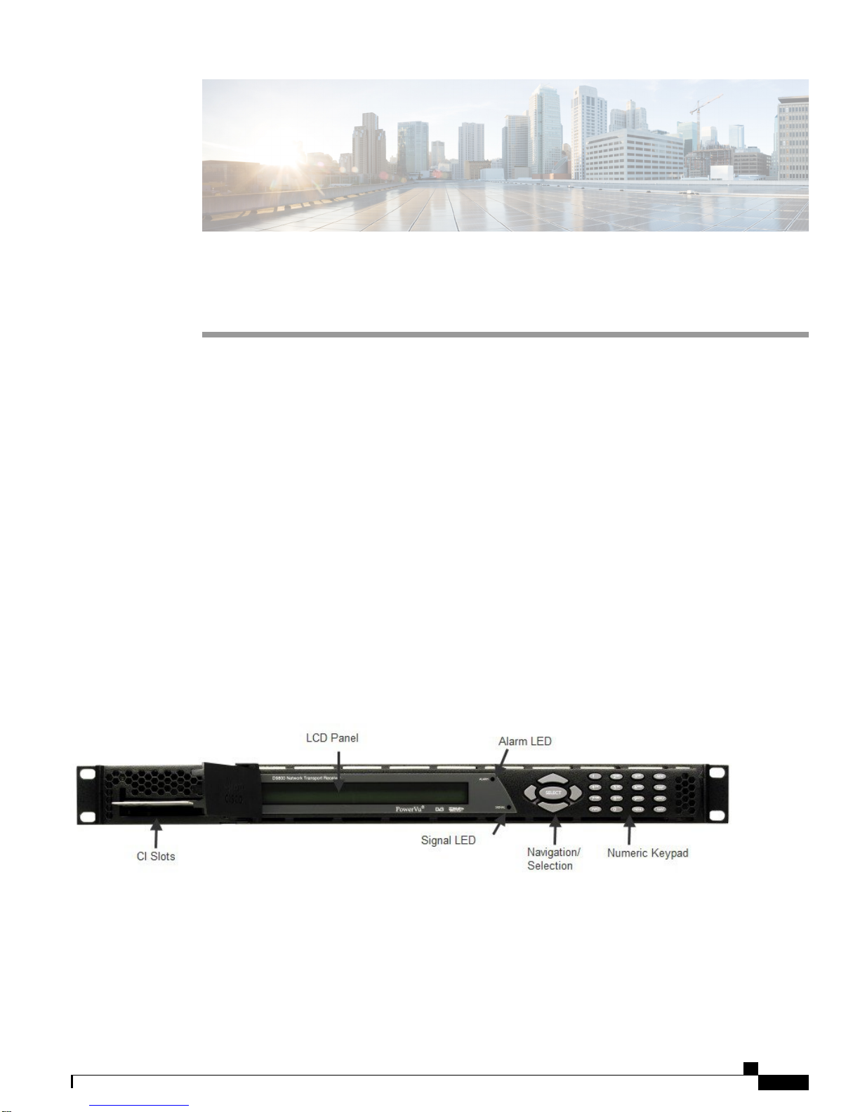
About the Front Panel
You can use the controls and indicators on the front panel to operate the D9800 receiver. These include the
numeric keypad, the navigation or selection keypad, the LCD, the alarm and signal indicators. These are
shown in the following illustration.
Figure 1: D9800 Front Panel
LCD
The LCD provides information on the selections available at any menu level, current settings for parameters,
and certain status and alarm indications. This is a 2x40, backlit LCD display. The top line may be status data
Cisco D9800 Network Transport Receiver Version 3.11 Installation and Configuration Guide
1
Page 2

Front Panel LEDs
or identifier information. It can also display optional functions available for tuning operations. The bottom
line will show selections or parameter values available using the navigation/selection keypad. The items are
selected by pressing the SELECT key or the down arrow key on the navigation/selection keypad.
Front Panel LEDs
The functions of the LEDs are described in the table below.
Getting Started
DescriptionSignal State/ColorLED
Solid for five seconds indicates a Warning.RedAlarm
Flashing indicates an Alarm.Red
GreenSignal
Green
Off
Solid indicates all of the following conditions:
active RF, ASI, and IP inputs are enabled, locked
•
to a signal, and are not muted.
all outputs are operating without an error.
•
Flashing indicates one of the following conditions:
difficulty with an input, route, or output.
•
one or more of the inputs are not synchronized.
•
one or more ASI outputs are routed, but muted
•
by a fault condition.
receiver is not authorized to receive the program.
•
Off indicates all of the following conditions:
no RF input signal is available, enabled or
•
detected, or the input is muted.
no ASI input present.
•
no IP input present.
•
no valid inputs are available.
•
CI Slots
The CI slots allow the use of CAM (Conditional Access Module) Smart Card to decrypt purchased
programming.
Cisco D9800 Network Transport Receiver Version 3.11 Installation and Configuration Guide
2
Page 3

Getting Started
Navigation/Selection Keypad
The navigation keys on the front panel (LEFT, RIGHT, UP, and DOWN) and the SELECT key are the primary
controllers. Each navigation key performs various functions, depending on the current state of the menu system
(that is, sometimes the left navigation key backspaces over an entry and sometimes moves the cursor to a
different menu item). Once the cursor is over the desired function, pressing the SELECT (center key) key
selects the current item. Pressing the SELECT key stores any entered values.
The table below describes the front panel keys.
Navigation/Selection Keypad
FunctionFront Panel Key
Left arrow
Right arrow
INFO
MENU
MAP
When moving through menus, it highlights the menu item to the left. When
entering data, it moves the cursor to the left. In some menus, it backspaces
over the data entry.
When moving through menus, it highlights the menu item to the right. When
entering data, it moves the cursor to the right.
Highlights the menu item above.Up arrow
Highlights the menu item below.Down arrow
Runs the highlighted command or opens the highlighted menu.SELECT
Displays context-sensitive help messages, when available.
When entering characters in numeric or alphanumeric fields, this key is used
to toggle between uppercase and lowercase.
Starts the on-screen display, and it also functions as an Escape key, allowing
you to back out of menus and data entry fields.
Toggles between program entry and channel number.ADV
Allows you to edit, insert, and delete the Digital Program Mapping (DPM)
modes on program entries or PIDs within program entries.
Numeric Keypad
The numeric keypad is used to enter alphanumeric values. The MENU key sets the software to the initial
menu and returns to the previous menu. The MENU key can also be used to cancel a numeric entry at any
point during the entry sequence, and the left arrow key allows backspacing through the entry.
Saves and applies the setting changes to the receiver.APPLY
For future use.NAV
Cisco D9800 Network Transport Receiver Version 3.11 Installation and Configuration Guide
3
Page 4
Locking or Unlocking the Front Panel
Pressing the numeric keys 2 to 9 once will enter the respective digit into a data entry field. Pressing these
buttons again will enter the first of the letters displayed beside the number. Repeatedly pressing the button
will toggle through all of the possible choices.
When entering text, press the 1 key twice to insert a space.
To delete a character, press 0 twice.
Locking or Unlocking the Front Panel
Depending on the default settings, the receiver is shipped with a locked or unlocked front panel. You can lock
or unlock the front panel using the front panel keypad or the web GUI.
Getting Started
Step 1
Step 2
Step 3
Step 4
Step 5
From the D9800 web GUI, choose System Settings > Front Panel. Or, from the Main Menu of the D9800 front panel,
choose Setup > Admin > KB Lock.
Check the Enable Automatic Front Panel Keyboard Lock check box or choose the Enable front panel menu to lock
the front panel. To permanently unlock the front panel, change the KB Lock state to Disabled or uncheck the check box.
In the Keyboard Lock Timeout field, enter the keypad lock timeout period. The lock timeout period takes effect when
the keypad has not been touched (for example, a key has not been pressed) when on the Main Menu for the set period.
Avoid setting the period to a short duration when the keypad is used often. Enter a value in the range from 5 to 1800
seconds. The default is 60 seconds.
Press MENU until the Startup screen is displayed.
From the Startup screen, press SELECT, and then INFO.
Note
If the lock level is 3 or 4, you must enter a password to unlock the front
panel.
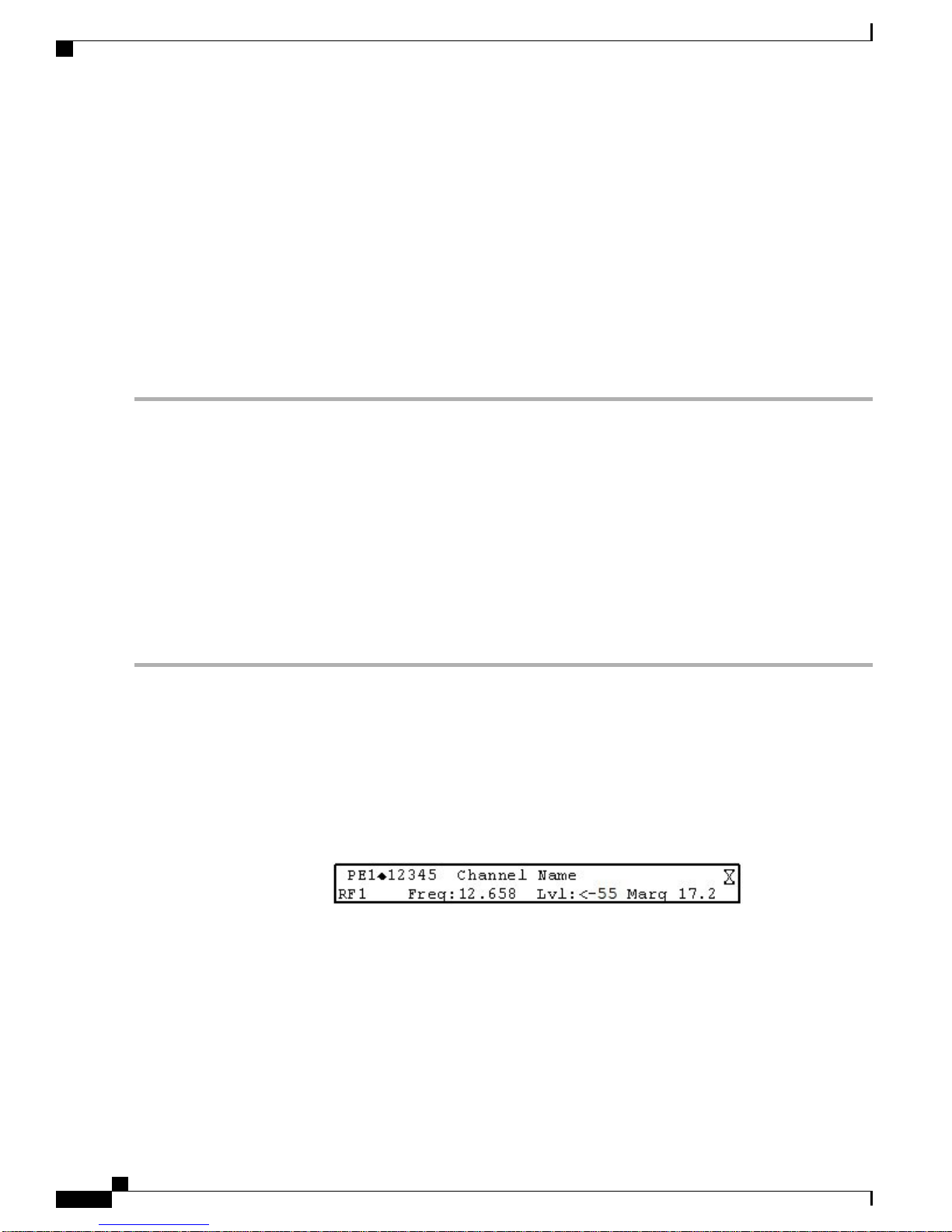
Startup Screen
The Startup screen on the D9800 front panel displays basic signal and program information. The following
is an example of the Startup screen:
Figure 2: D9800 Startup Screen
The table below describes the parameters displayed on the Startup screen.
Cisco D9800 Network Transport Receiver Version 3.11 Installation and Configuration Guide
4
Page 5

Getting Started
Startup Screen
DescriptionParameter
PE
RF
DEGD
Displays the program entry. The receiver supports up to 32 program entries.
Single-Stream unit: Only PE1 supports PowerVu descrambling. Do not assign
PowerVu channels to PE2 to PE32. If any PowerVu channels are assigned to
PE2 to PE32, all Service PIDs associated with these channels will be dropped
from the transport output.
Multi-Stream unit: All 32 PEs support PowerVu descrambling. You may need
the appropriate licenses to permit configuration of channels to the PEs.
All 32 program entries can use the Conditional Access Modules (CAMs).
Displays the channel number for program monitoring.12345
Indicates the name of the monitored program.Channel Name
Displays the active RF input port. ASI or IP is shown if the ASI or IP port is
active.
Displays the downlink frequency of the tuned signal, in GHz.Freq
Displays the signal level, in dBm.Lvl
Indicates the carrier-to-noise (C/N) margin, in dB.Marg
The Degraded indicator only appears if there is degraded tuning information
in use. This occurs if the SI tables are not consistent on the incoming stream.
The receiver will attempt to identify the service list based on the information
available. Check the SI acquisition and stream information to ensure that the
channels, network, and tuning information are operating as expected.
Viewing the Channel Authorization Status
From the Startup screen of the D9800 front panel, press the right or left arrow keys on the keypad to move to
the PE entry authorization status screen. This screen displays all the available channels and whether the
channels are authorized (Y or N).
LCD Symbol
Various symbols will periodically appear in the top right-hand corner of the LCD panel, indicating which
user actions are currently acceptable. The following displays an example of the location of the symbol:
Cisco D9800 Network Transport Receiver Version 3.11 Installation and Configuration Guide
5
Page 6

Startup Screen
The table below describes the symbols.
DescriptionLCD Symbol
Indicates that parameters are being saved in the background. You can
continue to perform any operation desired.
Note
Indicates that the INFO key is active. In most cases, this will display
contextual information on the LCD screen.
Indicates that the SELECT key is active.
The Download In Progress (DL) symbol indicates that the receiver is
currently downloading a software update and storing it into memory in the
background.
Note
Getting Started
If a power-cycle/interruption occurs while the hourglass is
displayed, some parameters may not be saved. Refrain from
powering off the unit while the hourglass is displayed.
Service interruption occurs during a reboot, which is always
required during a software update.
The Download Trigger (DT) symbol indicates that a new software is ready
for download, but a download trigger by the receiver is required before it
is downloaded.
Note
Service interruption occurs during a reboot, which is always
required during a software update.
The Download symbol indicates that a software download for a version of
software already in memory has been detected.
The Disaster Recovery (DR) symbol indicates that a disaster is declared on
the current receiver.
The NIT Retune (NR) symbol indicates that a NIT retune recovery is in
progress on the current receiver.
o
The Session Open symbol indicates that you are changing a group of related
items.
Cisco D9800 Network Transport Receiver Version 3.11 Installation and Configuration Guide
6
Page 7

Getting Started
Adjusting the LCD Contrast
Adjusting the LCD Contrast
Step 1
Step 2
Step 3
From the Main Menu of the D9800 front panel, choose Setup > Admin > LCD Contrast.
Choose the contrast of the LCD menu panel. The range is from 1 (lowest contrast) to 30 (highest contrast).
Save the settings.
Logging on to the D9800 Web GUI
Step 1
Step 2
Step 3
Step 4
Step 5
Open a web browser.
Type the IP address of the D9800 Network Transport Receiver in the address bar and press Enter. You can view and
configure the IP address in the following front panel menu: Setup > IP > IP > IP Address.
By default, the remote access is set up for a secure HTTPS connection. An untrusted warning message is displayed for
you to add the current address as an exception. You must add the current IP address as an exception to access the web
GUI. For more information on the HTTP setting, see Configuring the Remote Access Protocols.
In the Username and Password fields, enter the username and password. The default username is admin, and the default
password is localadmin.
Click Log In.
Note
If you check the Remember username check box, the user name will be remembered the next time you log
into the web GUI.
Changing the Login Password
Each user, including the admin user, can only modify their own password. The password complexity feature
is only available to users with administrative privileges. For more information, see Changing the Password
Complexity.
Step 1
Step 2
Step 3
Step 4
Step 5
From the D9800 web GUI, choose System Settings > Account Management.
In the Enter Current Password field, type the current login password.
In the Enter New Password field, type the new login password.
In the Re-enter New Password field, type the new login password again to confirm. Once the password change is
successful, the user will be directed to the login screen to re-enter their username and password.
Click Apply.
Cisco D9800 Network Transport Receiver Version 3.11 Installation and Configuration Guide
7
Page 8

D9800 Web GUI Environment
D9800 Web GUI Environment
The following is an example of the D9800 web GUI page:
Figure 3: D9800 Web GUI
Getting Started
The following table displays the general buttons on the D9800 web GUI.
Refresh
Cisco D9800 Network Transport Receiver Version 3.11 Installation and Configuration Guide
8
DescriptionButton
Saves and applies the settings to the receiver.Apply
Reads existing data from the unit. If edits were made in a setup page, then
unsaved changes are discarded.
Discards any changes made and sets data to default values.Reset Defaults
Resets counters on the displayed page.Clear Counters
Page 9

Getting Started
Alarms/Warnings
The top right corner of the D9800 web GUI displays the total number of active alarms ( ), active warnings
( ), and clear messages ( ). Clear messages is calculated as follows: total number of alarms + total
number of warnings - total number of active alarms - total number of active warnings.
To view a detailed list of alarms and warnings, click the Alarms or Warnings link and a pop-up window is
displayed with a list of all the active alarms or active warnings. Click an alarm or warning to open the Status
page for more information.
Viewing the Summary Overview
The Summary Dashboard page displays the main settings of the D9800 Network Transport Receiver. To view
the Summary Dashboard page, choose Summary from the D9800 web GUI.
You can customize the Summary Dashboard by clicking Add/Remove Module or by clicking x at the top
right corner of each module. Each module has a maximize and minimize button, allowing you to view or hide
various modules. The refresh button for each module allows you to refresh the data for the selected module
only.
The table below describes the available modules.
D9800 Web GUI Environment
Current Input Status
Tuner Performance
Channel Status
FEC Decoder Status
DescriptionModule
Displays channel and service information.Decoded Program Status
Displays the current RF Tuning Status information,
including the downlink frequency and signal status.
Displays the satellite dish status, such as the C/N
Margin and Signal Level.
Displays the current video information.Video Status
Displays the channel status information, such as the
type of CA used and whether the receiver is
authorized to receive the signal.
Displays the PIDs associated with the channels.PID Information
Displays the CAM card information.CI Status
Displays the currently active alarms and warnings.Most Recent Alarm/Warning
Displays the Forward Error Correction (FEC) status,
such as number of FEC columns and overhead
percentage.
Cisco D9800 Network Transport Receiver Version 3.11 Installation and Configuration Guide
9
Page 10

Basic Vs. Advanced Mode
Auto-Refresh
The system automatically refreshes the Summary Dashboard page every minute. Click Auto Refresh: On/Off
to toggle between enabling or disabling the automatic refresh feature.
Basic Vs. Advanced Mode
All the D9800 features are available in the Advanced mode (default). However, you have the option of limiting
the features available by switching to the Basic mode. The mode option is available at the top right-hand
corner of the D9800 web GUI.
Getting Started
The switch affects all pages, not only the current page.Note
The following is a list of features that are NOT included in the Basic mode:
Quick Setup
The following table provides the most common tasks to initially configure the D9800 Network Transport
Receiver.
AFC Limit, Input Selection, Polarisation, Orbital Posn, and East/West Flag options in RF Input Selection
•
area of the RF Input Setup page.
Orbital Validation Status and Orbital Validation Date status fields in the Tuner Performance area of
•
the RF Input Setup page.
Muting Threshold, Disaster Recovery, Disaster Recovery Status, Channel Selection, Cue Tone
•
(single-stream only), and Decode Enable (single-stream only) menu options.
CI Component Setup in CI Setup page.
•
DescriptionTask
Set up the network connection.Setting up the Network Connection
Tuning to an RF Input, Tuning to the ASI Input,
Tuning to the MPEGoIP Input, or Tuning to the ABR
Input
Acquire and configure one of the following inputs:
RF, ASI, IP, or ABR.
Cisco D9800 Network Transport Receiver Version 3.11 Installation and Configuration Guide
10
Page 11

Getting Started
Quick Setup
DescriptionTask
Assign a program channel to a program entry.Assigning a Channel to a Program Entry
Configuring the ASI or MPEGoIP Output General
Settings and Configuring the ASI or MPEGoIP Output
Mode
Configuring the SDI Outputs
Configuring the ASI or MPEGoIP Output General
Settings and Configuring MPEG over IP or IP Data
Streams
Set the following ASI output parameters:
Output Mode - We recommend to set it to MAP
•
Service Channels Only. Select Yes if requested
to Resync All.
Descramble Mode
•
Insert Null Packet - Set to Yes.
•
Choose the SDI1 and SDI2 outputs. The SDI outputs
are only available on units with the SDI option
installed (D9800-3G-SDI).
Configure the MPEG over IP output and stream
settings. The MPEGOIP outputs are only available
on units with the MPEGOIP input/output option
installed (D9800-SS-MPEGOIP).
For multi-stream units (D9800-MS-MPEGOIP),
configure the IP data output and stream settings.
Set the DPM mode.Typical Digital Program Mapping Setup
Cisco D9800 Network Transport Receiver Version 3.11 Installation and Configuration Guide
11
Page 12

Quick Setup
Getting Started
Cisco D9800 Network Transport Receiver Version 3.11 Installation and Configuration Guide
12
 Loading...