

Page 1

Cisco D9054
HDTV Encoder
Installation and Operation Guide
Software Version 4.2
Page 2

Please Read This Entire Guide
Veuillez lire entièrement ce guide
Bitte das gesamte Handbuch durchlesen
Sírvase leer completamente la presente guía
Si prega di leggere completamente questa guida
Important:
Please read this entire guide before you install or operate this product. Give
particular attention to all safety statements.
Important:
Veuillez lire entièrement ce guide avant d'installer ou d'utiliser ce produit. Prêtez
une attention particulière à toutes les règles de sécurité.
Zu beachten:
Bitte lesen Sie vor Aufstellen oder Inbetriebnahme des Gerätes dieses Handbuch in
seiner Gesamtheit durch. Achten Sie dabei besonders auf die Sicherheitshinweise.
Importante:
Sírvase leer la presente guía antes de instalar o emplear este producto. Preste
especial atención a todos los avisos de seguridad.
Importante:
Prima di installare o usare questo prodotto si prega di leggere completamente
questa guida, facendo particolare attenzione a tutte le dichiarazioni di sicurezza.
Page 3

Notices
Trademark Acknowledgements
Cisco and the Cisco logo are trademarks or registered trademarks of Cisco and/or its
affiliates in the U.S. and other countries. A listing of Cisco's trademarks can be found at
www.cisco.com/go/trademarks
Manufactured under license from Dolby Laboratories. Dolby and the double-D symbol
are trademarks of Dolby Laboratories.
Other third party trademarks mentioned are the property of their respective owners.
The use of the word partner does not imply a partnership relationship between Cisco
and any other company. (1009R).
Publication Disclaimer
Cisco Systems, Inc. assumes no responsibility for errors or omissions that may appear in
this publication. We reserve the right to change this publication at any time without
notice. This document is not to be construed as conferring by implication, estoppel, or
otherwise any license or right under any copyright or patent, whether or not the use of
any information in this document employs an invention claimed in any existing or later
issued patent.
Copyright
.
© 2011 Cisco Systems, Inc. All rights reserved. Printed in the United States of America.
Information in this publication is subject to change without notice. No part of this
publication may be reproduced or transmitted in any form, by photocopy, microfilm,
xerography, or any other means, or incorporated into any information retrieval system,
electronic or mechanical, for any purpose, without the express permission of Cisco
Systems, Inc.
AVC/MPEG-4/H.264 Products
With respect to each AVC/MPEG-4/H.264 product, Cisco is obligated to provide the
following notice:
THIS PRODUCT IS LICENSED UNDER THE AVC PATENT PORTFOLIO LICENSE
FOR THE PERSONAL AND NON-COMMERCIAL USE OF A CONSUMER TO (i)
ENCODE VIDEO IN COMPLIANCE WITH THE AVC STANDARD ("AVC VIDEO")
AND/OR (ii) DECODE AVC VIDEO THAT WAS ENCODED BY A CONSUMER
ENGAGED IN A PERSONAL AND NON-COMMERCIAL ACTIVITY AND/OR WAS
OBTAINED FROM A VIDEO PROVIDER LICENSED TO PROVIDE AVC VIDEO. NO
LICENSE IS GRANTED OR SHALL BE IMPLIED FOR ANY OTHER USE.
ADDITIONAL INFORMATION MAY BE OBTAINED FROM MPEG LA, L.L.C. SEE
HTTP://WWW.MPEGLA.COM.
Accordingly, please be advised that service providers, content providers and
broadcasters are required to obtain a separate use license from MPEG LA prior to any
use of AVC/MPEG-4/H.264 encoders and/or decoders.
Page 4

Page 5
Safety Precautions
Protect yourself from electric shock and your system from damage!
• This product complies with international safety and design standards. Observe all safety
procedures that appear throughout this guide, and the safety symbols that are affixed to
this product.
• If circumstances impair the safe operation of this product, stop operation and secure this
product against further operation.
Avoid personal injury and product damage! Do not proceed beyond any symbol until
you fully understand the indicated conditions!
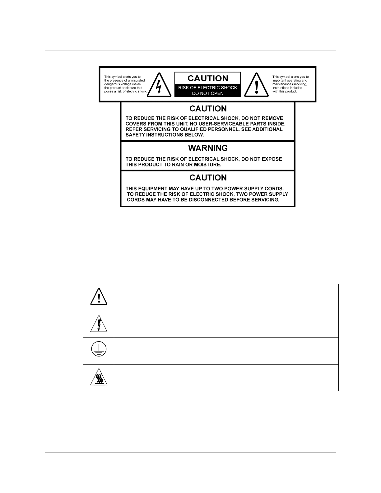
You will find this symbol on the product and/or in the literature that
accompanies this product.
It indicates important operating or maintenance instructions.
You may find this symbol on the product and/or in the literature that
accompanies this product.
It indicates a live terminal; the symbol pointing to the terminal device.
You may find this symbol on the product and/or in the literature that
accompanies this product.
It indicates a protective earth terminal.
You may find this symbol on the product and/or in the literature that
accompanies this product.
It indicates excessive or dangerous heat.
Power
• Important! This is a Class I product. You must earth this product.
This equipment may have up to two power supply cords. To reduce the risk of electric
shock, two power supply cords may have to be disconnected before servicing.
• This product plugs into a socket-outlet. The socket-outlet must be near this product, and
must be easily accessible.
4038938 Rev A D9054 HDTV Encoder Installation and Operation Guide v
Page 6

Safety Precautions, Continued
• Connect this product only to the power source that is indicated on the rear panel of this
product.
• If this product does not have a mains power switch, the power cord serves this purpose.
Enclosure
• Do not allow moisture to enter this product.
• Do not open the enclosure of this product unless otherwise specified.
• Do not push objects through openings in the enclosure of this product.
Cables
• Always disconnect all power cables before servicing this product.
• Always pull on the plug or the connector to disconnect a cable. Never pull on the cable
itself.
• Do not walk on or place stress on cables or plugs.
Factory service
• Refer service only to service personnel who are authorized by the factory.
vi D9054 HDTV Encoder Installation and Operation Guide 4038938 Rev A
Page 7

Règles de sécurité
Protégez-vous des risques d'électrocution et protégez votre système contre les
endommagements éventuels.
• Ce produit respecte les standards internationaux de sécurité et de conception. Veuillez
observer toutes les procédures de sécurité qui apparaissent dans ce guide, ainsi que les
symboles de sécurité qui figurent sur le produit.
• Si, du fait des circonstances, ce produit cesse de fonctionner normalement, cessez de
l'utiliser et empêchez-en l'utilisation future.
Évitez le risque de blessures et de dommages aux produits! Ne procédez à aucune tâche
tant que vous n'aurez pas entièrement assimilé les conditions indiquées par un symbole!
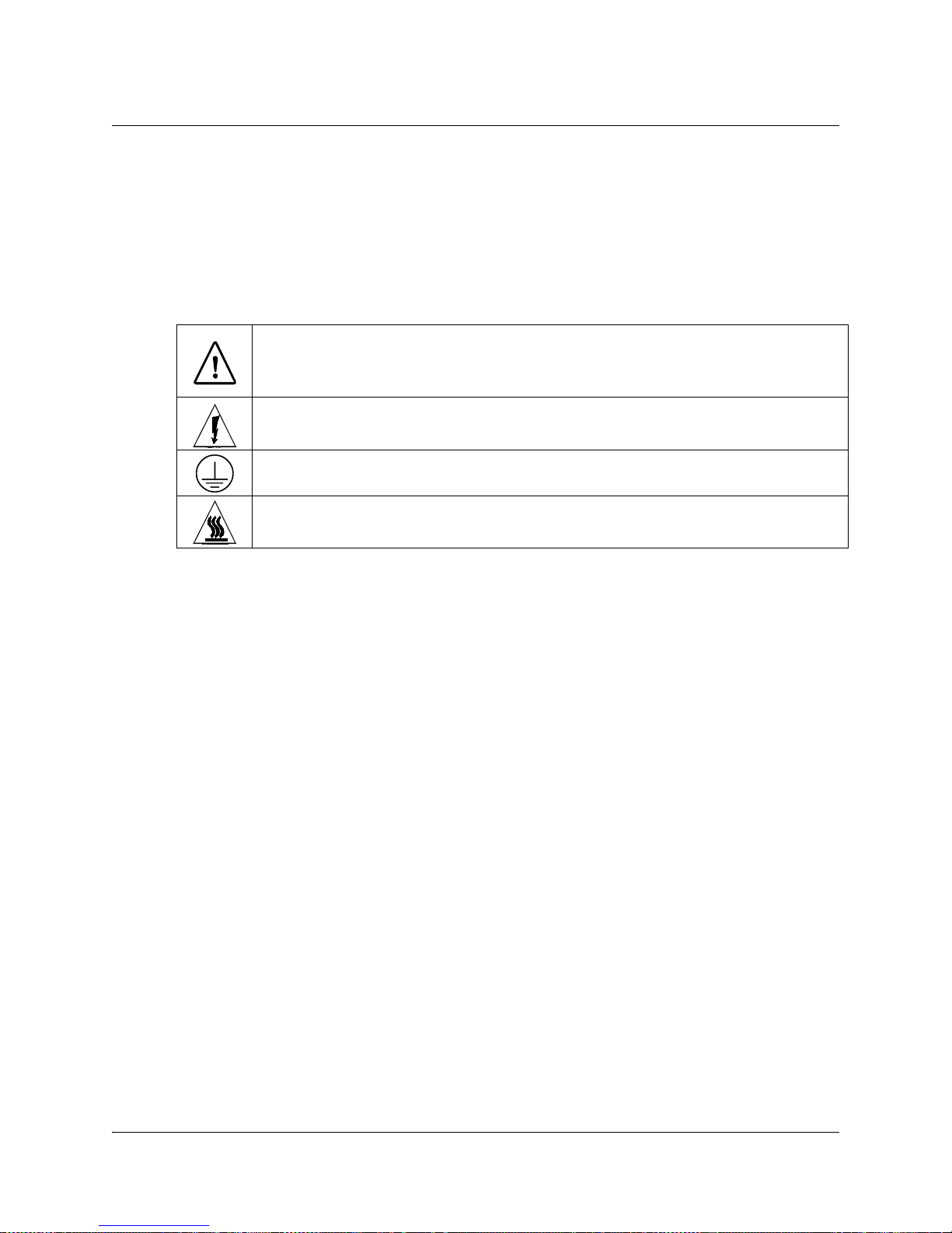
Ce symbole figure dans la documentation accompagnant ce produit. Il indique
d'importantes instructions de fonctionnement ou d'entretien.
Ce symbole peut être attaché à ce produit. Il indique une borne sous tension; la
direction indique la borne.
Ce symbole peut être attaché à ce produit. Il indique une borne de terre de
protection.
Ce symbole peut être attaché à ce produit. Il indique une température excessive ou
dangereuse.
Alimentation
• Important! Ce produit fait partie de la classe I. Vous devez le mettre à la terre.
• Ce produit se branche dans une prise murale. Cette dernière doit être placée à proximité
du produit et doit être facilement accessible.
• Ne branchez ce produit qu'à la source d'alimentation indiquée sur son panneau arrière.
• Si ce produit n'a pas d'interrupteur d'alimentation générale, le cordon d'alimentation
remplit ce rôle.
Enceinte
• Ne laissez pas l'humidité pénétrer dans ce produit.
• N'ouvrez pas l'enceinte de ce produit, sauf instructions contraires.
• Ne forcez pas d'objets dans les ouvertures du boîtier.
Câbles
• Débranchez toujours tous les cordons d'alimentation avant de réparer ce produit.
• Tirez toujours sur la prise ou le connecteur pour débrancher un câble. Ne tirez jamais
directement sur le câble.
• Ne marchez pas sur les câbles ou les prises et n'y exercez aucune pression.
Réparations effectuées à l'usine
• Ne confiez les travaux de réparations qu'au personnel autorisé par l'usine.
4038938 Rev A D9054 HDTV Encoder Installation and Operation Guide vii
Page 8

Sicherheitsvorkehrungen
Schützen Sie sich gegen elektrischen Schlag, und Ihr Gerät gegen Beschädigung!
• Dieses Gerät entspricht internationalen Sicherheits-und Ausführungsnormen. Beachten
Sie alle in diesem Handbuch enthaltenen Sicherheitshinweise sowie die am Gerät
angebrachten Warnzeichen.
• Sollten örtliche Umstände den sicheren Betrieb dieses Gerätes beeinträchtigen, schalten
Sie es ab und sichern es gegen weitere Benutzung.
Vermeiden Sie Verletzungen sowie Beschädigung des Gerätes! Wenn Sie zu einem der
folgenden Warnzeichen gelangen, nicht weiterarbeiten, bis Sie seine Bedeutung voll
verstanden haben!
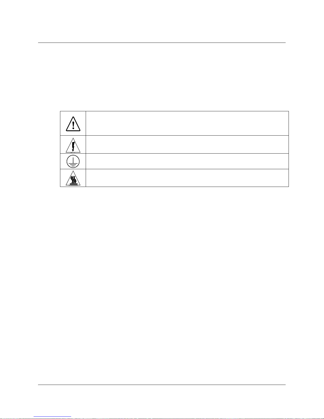
Dieses Symbol erscheint auf dem Gerät und/oder in der ihm beiliegenden Literatur.
Es bedeutet wichtige, zu beachtende Betriebs-oder Wartungsanweisungen.
Wenn dieses Zeichen am Gerät angebracht ist, warnt es vor einer
spannungsführenden Stelle.
Dieses Symbol kennzeichnet auf dem Gerät die Anschlußstelle der Sicherheitserde.
Wenn dieses Zeichen am Gerät angebracht ist, warnt es vor heißen Stellen, die zu
Verbrennungen führen können.
Netzspannung
• Wichtig! Dieses Gerät ist ein Produkt der Schutzklasse I. Es muß geerdet werden.
• Das Gerät ist an einer Steckdose anzuschließen. Diese muß sich leicht zugänglich in
unmittelbarer Nähe des Gerätes befinden.
• Die Netzversorgung muß den auf der Rückwand des Gerätes angegebenen Werten
entsprechen.
• Falls sich kein Hauptschalter am Gerät befindet, dient das Netzkabel diesem Zweck.
Gehäuse
• Das Innere des Gerätes ist vor Feuchtigkeit zu schützen.
• Das Gehäuse ist nicht zu öffnen.
• Niemals einen Gegenstand durch die Gehäuseöffnungen einführen!
Kabel
• Vor jeglicher Wartung des Gerätes sind alle Kabel zu entfernen.
• Hierzu grundsätzlich am Stecker oder Verbindungsstück und niemals am Kabel selber
ziehen.
• Nicht auf die Kabel oder Stecker treten oder diese einer Zugbelastung aussetzen.
Hersteller-Wartung
Wartungsarbeiten sind nur durch vom Hersteller autorisierte Techniker vorzunehmen.
viii D9054 HDTV Encoder Installation and Operation Guide 4038938 Rev A
Page 9
Precauciones de seguridad
¡Protéjase contra la electrocución y proteja su sistema contra los daños!
• Este producto cumple con los criterios internacionales de seguridad y diseño. Observe
todas los procedimientos de seguridad que aparecen en esta guía, y los símbolos de
seguridad adheridos a este producto.
• Si las circunstancias impiden la operación segura de este producto, suspenda la operación
y asegure este producto para que no siga funcionando.
¡Evite lastimarse y evite dañar el producto! No avance más allá de cualquier símbolo
hasta comprender completamente las condiciones indicadas!
Encontrará este símbolo en el impreso que acompaña a este producto. Este símbolo
indica instrucciones importantes de funcionamiento o mantenimiento.
Es posible que este símbolo esté pegado al producto. Este símbolo indica un terminal
vivo, la flecha apunta hacia el aparato terminal
Podría encontrar este símbolo pegado al producto. Este símbolo indica un terminal
de protección de tierra.
Podría encontrar este símbolo pegado al producto. Este símbolo indica calor
excesivo o peligroso.
Power
• Importante! Este es un producto de Clase I. Tiene que estar conectado a tierra.
• Este producto se conecta a un enchufe. El enchufe necesita estar cerca del producto y ser
fácilmente accesible.
• Conecte este producto únicamente a la fuente de suministro eléctrico indicada en el panel
posterior del producto.
• Si el producto no tiene interruptor para la linea principal, utilice el cordón toma de
corriente para este propósito.
Cubierta
• No permita que la humedad penetre en este producto.
• No abra la cubierta del producto a menos que se indique lo contrario.
• No introduzca objetos a través de las aberturas de la cubierta del producto.
Cables
• Siempre desconectar todos los cables eléctricos antes de revisar o reparar el producto.
• Tire siempre del enchufe o del conector para desconectar un cable. Nunca tire del cable
mismo.
• No camine ni aplique presión sobre los cables o enchufes..
Revisión y reparación de fábrica
Solo personal aprobado por la fábrica puede darle servicio al producto.
4038938 Rev A D9054 HDTV Encoder Installation and Operation Guide ix
Page 10
Precauzioni di sicurezza
Proteggetevi da scosse elettriche e proteggete il vostro sistema da possibili danni!
• Questo prodotto soddisfa le norme internazionali per la sicurezza ed il design. Seguite
tutte le procedure di sicurezza contenute in questa guida e i simboli di sicurezza applicati
al prodotto.
• Se circostanze avverse compromettono la sicurezza d'uso di questo prodotto,
interrompetene l'uso e assicuratevi che il prodotto non venga più utilizzato.
Evitare infortuni alla persona e danni al prodotto! Non procedere oltre a qualunque
simbolo fino a quando non si siano comprese pienamente le condizioni indicate!
Questo simbolo, che appare nella letteratura di accompagnamento del prodotto,
indica importanti istruzioni d'uso e di manutenzione.
Sul prodotto potete vedere questo simbolo che indica un dispositivo terminale sotto
tensione; la freccia punta verso il dispositivo.
Potrete trovare il presente simbolo applicato a questo prodotto. Questo simbolo
indica un terminale protettivo di messa a terra.
Potrete trovare il presente simbolo attaccato a questo prodotto. Questo simbolo
indica un calore eccessivo o pericoloso.
Alimentazione
• Importante! Questo prodotto è di Classe I. Va messo a terra.
• Questo prodotto si inserisce in una presa di corrente. La presa di corrente deve essere in
prossimità del prodotto, e deve essere facilmente accessibile.
• Collegare questo prodotto solamente alla fonte di alimentazione indicata sul pannello
posteriore di questo prodotto.
• Se questo prodotto non è dotato di un interruttore principale, il cavo di alimentazione
funge a questo scopo.
Chiusura
• Proteggete da umidità questo prodotto.
• Non aprire la chiusura di questo prodotto a meno che non sia specificato diversamente.
Non inserire oggetti attraverso le fessure della chiusura.
Cavi
• Staccare sempre tutti i cavi di alimentazione prima di svolgere l'assistenza tecnica al
prodotto.
• Per scollegare un cavo tirate la spina o il connettore, non tirare mai il cavo stesso.
• Non calpestare o sottoporre a sollecitazioni i cavi o le prese.
Riparazionoi di fabbrica
• Per le riparazioni contattate solamente personale tecnico autoizzato dalla fabbrica.
x D9054 HDTV Encoder Installation and Operation Guide 4038938 Rev A
Page 11

Important Safety Instructions
WARNING:
Read and Retain Instructions
Carefully read all safety and operating instructions before operating this equipment, and
retain them for future reference.
Follow Instructions and Heed Warnings
Follow all operating and use instructions. Pay attention to all warnings and cautions in the
operating instructions, as well as those that are affixed to this equipment.
Terminology
The terms defined below are used in this document. The definitions given are based on
those found in safety standards.
Service Personnel - The term service personnel applies to trained and qualified individuals
who are allowed to install, replace, or service electrical equipment. The service personnel
are expected to use their experience and technical skills to avoid possible injury to
themselves and others due to hazards that exist in service and restricted access areas.
User and Operator - The terms user and operator apply to persons other than service
personnel.
Ground(ing) and Earth(ing) - The terms ground(ing) and earth(ing) are synonymous. This
document uses ground(ing) for clarity, but it can be interpreted as having the same meaning
as earth(ing).
Electric Shock Hazard
This equipment meets applicable safety standards.
To reduce risk of electric shock, perform only the instructions that are included in the
operating instructions. Refer all servicing to qualified service personnel only.
Electric shock can cause personal injury or even death. Avoid direct contact with dangerous
voltages at all times. The protective ground connection is essential to safe operation and
must be verified before connecting the power supply.
Know the following safety warnings and guidelines:
• Dangerous Voltages
- Only qualified service personnel are allowed to perform equipment installation or
replacement.
- Only qualified service personnel are allowed to remove chassis covers and access any
of the components inside the chassis.
• Grounding
- Do not violate the protective grounding by using an extension cable, power cable, or
autotransformer without a protective ground conductor.
- Take care to maintain the protective grounding of this equipment during service or
repair and to re-establish the protective grounding before putting this equipment back
into operation.
4038938 Rev A D9054 HDTV Encoder Installation and Operation Guide xi
Page 12

Important Safety Instructions, Continued
WARNING:
WARNING:
Installation Site
When selecting the installation site, comply with the following:
• Protective Ground - The protective ground lead of the building's electrical installation
should comply with national and local requirements.
• Environmental Condition - The installation site should be dry, clean, and ventilated. Do
not use this equipment where it could be at risk of contact with water. Ensure that this
equipment is operated in an environment that meets the requirements as stated in this
equipment's technical specifications, which may be found on this equipment's data sheet.
Installation Requirements
Allow only qualified service personnel to install this equipment.
The installation must conform to all local codes and regulations.
Equipment Placement
Ventilation
Avoid personal injury and damage to this equipment. An unstable mounting surface
may cause this equipment to fall.
To protect against equipment damage or injury to personnel, comply with the following:
• Install this equipment in a restricted access location.
• Do not install near any heat sources such as radiators, heat registers, stoves, or other
equipment (including amplifiers) that produce heat.
• Place this equipment close enough to a mains AC outlet to accommodate the length of
this equipment's power cord.
• Route all power cords so that people cannot walk on, place objects on, or lean objects
against them. This may pinch or damage the power cords. Pay particular attention to
power cords at plugs, outlets, and the points where the power cords exit this equipment.
• Use only with a cart, stand, tripod, bracket, or table specified by the manufacturer, or sold
with this equipment.
• Make sure the mounting surface or rack is stable and can support the size and weight of
this equipment.
• The mounting surface or rack should be appropriately anchored according to
manufacturer's specifications. Ensure this equipment is securely fastened to the mounting
surface or rack where necessary to protect against damage due to any disturbance and
subsequent fall.
This equipment has openings for ventilation to protect it from overheating. To ensure
equipment reliability and safe operation, do not block or cover any of the ventilation
openings. Install the equipment in accordance with the manufacturer's instructions.
xii D9054 HDTV Encoder Installation and Operation Guide 4038938 Rev A
Page 13
Important Safety Instructions, Continued
WARNING:
CAUTION:
CAUTION:
WARNING:
Rack Mounting Safety Precautions
Mechanical Loading
Make sure that the rack is placed on a stable surface. If the rack has stabilizing devices,
install these stabilizing devices before mounting any equipment in the rack.
Avoid personal injury and damage to this equipment. Mounting this equipment in the
rack should be such that a hazardous condition is not caused due to uneven mechanical
loading.
Reduced Airflow
When mounting this equipment in the rack, do not obstruct the cooling airflow through the
rack. Be sure to mount the blanking plates to cover unused rack space. Additional
components such as combiners and net strips should be mounted at the back of the rack, so
that the free airflow is not restricted.
Installation of this equipment in a rack should be such that the amount of airflow
required for safe operation of this equipment is not compromised.
Elevated Operating Ambient Temperature
Only install this equipment in a humidity- and temperature-controlled environment that
meets the requirements given in this equipment's technical specifications.
If installed in a closed or multi-unit rack assembly, the operating ambient temperature
of the rack environment may be greater than room ambient temperature. Therefore,
install this equipment in an environment compatible with the manufacturer's
maximum rated ambient temperature.
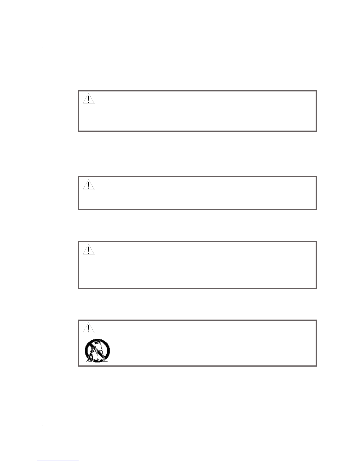
Handling Precautions
When moving a cart that contains this equipment, check for any of the following possible
hazards:
• Use caution when moving this equipment/cart combination to avoid injury from tipover.
• If the cart does not move easily, this condition may indicate obstructions or cables that
may need to be disconnected before moving this equipment to another location.
• Avoid quick stops and starts when moving the cart.
• Check for uneven floor surfaces such as cracks or cables and cords.
Avoid personal injury and damage to this equipment! Move any
equipment and cart combination with care. Quick stops, excessive force,
and uneven surfaces may cause this equipment and cart to overturn.
4038938 Rev A D9054 HDTV Encoder Installation and Operation Guide xiii
Page 14

Important Safety Instructions, Continued
Grounding
This section provides instructions for verifying that the equipment is properly grounded.
Safety Plugs (USA Only)
Equipment protection Class I - Cisco supplies a mains cord with a 3-terminal (groundingtype) safety plug. Do not defeat the safety purpose of the grounding-type or polarized
safety plug.
To properly ground this equipment, follow these safety guidelines:
• Grounding-Type Plug - For a 3-terminal plug (one terminal on this plug is a protective
grounding pin), insert the plug into a grounded mains, 3-terminal outlet.
Note: This plug fits only one way. If this plug cannot be fully inserted into the outlet,
contact an electrician to replace the obsolete 3-terminal outlet.
Safety Plugs (European Union)
• Class I Mains Powered Equipment - Provided with a 3-terminal AC inlet and requires
connection to a 3-terminal mains supply outlet via a 3-terminal power cord for proper
connection to the protective ground.
Note: The equipotential bonding terminal provided on some equipment is not designed
to function as a protective ground connection.
Equipotential Bonding
If this equipment is equipped with an external chassis terminal marked with the IEC 60417-
5020 chassis icon ( ), or 5017 ( ), the installer should refer to CENELEC standard EN
50083-1 or IEC standard IEC 60728-11 for correct equipotential bonding connection
instructions.
xiv D9054 HDTV Encoder Installation and Operation Guide 4038938 Rev A
Page 15
Important Safety Instructions, Continued
CAUTION:
WARNING:
AC Power
Important: This equipment is Class I equipment, it must be grounded.
• If this equipment plugs into an outlet, the outlet must be near this equipment, and must
be easily accessible.
• Connect this equipment only to the power sources that are identified on the equipmentrating label normally located close to the power inlet connector(s).
• If this equipment has two power sources be sure to disconnect all power sources before
working on this equipment.
• If this equipment does not have a main power switch, the power cord connector serves as
the disconnect device.
• Always pull on the plug or the connector to disconnect a cable. Never pull on the cable
itself.
• Unplug this equipment when unused for long periods of time.
Circuit Overload
Know the effects of circuit overloading before connecting this equipment to the power
supply.
Consider the connection of this equipment to the supply circuit and the effect that
overloading of circuits might have on overcurrent protection and supply wiring. Refer
to the information on the equipment-rating label when addressing this concern.
General Servicing Precautions
Avoid electric shock! Opening or removing this equipment's cover may expose you to
dangerous voltages.
Be aware of the following general precautions and guidelines:
• Servicing - Refer all servicing to qualified service personnel. Servicing is required when
this equipment has been damaged in any way, such as power supply cord or plug is
damaged, liquid has been spilled or objects have fallen into this equipment, this
equipment has been exposed to rain or moisture, does not operate normally, or has been
dropped.
• Wristwatch and Jewelry - For personal safety and to avoid damage of this equipment
during service and repair, do not wear electrically conducting objects such as a
wristwatch or jewelry.
• Lightning - Do not work on this equipment, or connect or disconnect cables, during
periods of lightning.
• Labels - Do not remove any warning labels. Replace damaged or illegible warning labels
with new ones.
• Covers - Do not open the cover of this equipment and attempt service unless instructed to
do so in the instructions. Refer all servicing to qualified service personnel only.
• Moisture - Do not allow moisture to enter this equipment.
• Cleaning - Use a damp cloth for cleaning.
4038938 Rev A D9054 HDTV Encoder Installation and Operation Guide xv
Page 16

Important Safety Instructions, Continued
Safety Checks - After service, assemble this equipment and perform safety checks
to ensure it is safe to use before putting it back into operation.
Accessories
Use only attachments or accessories specified by the manufacturer.
xvi D9054 HDTV Encoder Installation and Operation Guide 4038938 Rev A
Page 17

Contents
Safety Precautions.......................................................................................................................................v
Règles de sécurité......................................................................................................................................vii
Sicherheitsvorkehrungen........................................................................................................................ viii
Precauciones de seguridad........................................................................................................................ix
Precauzioni di sicurezza..............................................................................................................................x
Important Safety Instructions.....................................................................................................................xi
About This Manual................................................................................................................................. xxiii
Chapter 1 Quick Setup - Read Me First!
Connecting the Units........................................................................................................1-1
Front Panel Setup..............................................................................................................1-3
Chapter 2 Introduction
D9054 HD Encoder ...........................................................................................................2-2
Application Examples ......................................................................................................2-5
Video Interfaces.................................................................................................................2-6
Audio and Data Interfaces...............................................................................................2-7
Transport Stream Outputs...............................................................................................2-9
Control and Management Interfaces............................................................................2-10
Chapter 3 Installation
Section A - Rack Installation .................................................................................................3-2
General................................................................................................................................3-2
Installing the D9054 HD Encoder ...................................................................................3-3
Section B - Connector Panel .................................................................................................3-5
Overview............................................................................................................................3-5
Section C - Connecting the Input/Output Signals ..................................................................3-7
Connecting the Video Inputs...........................................................................................3-7
Connecting the Audio Inputs..........................................................................................3-8
Connecting to the Contact Closure Interface................................................................3-9
Connecting an External Alarm System........................................................................3-10
Connecting the Ethernet Management Interface........................................................3-11
Connecting the IP TS Outputs.......................................................................................3-12
Connecting the ASI Outputs and the ASI Monitor....................................................3-13
4038938 Rev A D9054 HDTV Encoder Installation and Operation Guide xvii
Page 18

Contents, Continued
Chapter 4 Front Panel Operation
About the Front Panel ......................................................................................................4-2
Keypad Convention..........................................................................................................4-4
Startup Screen....................................................................................................................4-5
Main Menu.........................................................................................................................4-6
PSI Menu ............................................................................................................................4-7
Video Menu .......................................................................................................................4-9
Audio Menu.....................................................................................................................4-13
Output Menu ...................................................................................................................4-22
System Menu ...................................................................................................................4-24
Chapter 5 Setup and Monitoring
Logging On to the Web Interface....................................................................................5-6
Changing the Password for the Web Interface.............................................................5-7
Web Interface - Summary Screen....................................................................................5-8
Tab Pages............................................................................................................................5-9
The Menu Bar and Buttons............................................................................................5-10
Context-Sensitive Online Help......................................................................................5-11
Section A - Setting Up Video...............................................................................................5-12
Setting Up the Video Input............................................................................................5-12
Setting Up the H.264 Video Encoder............................................................................5-13
3:2 Pulldown and 3:2 Pulldown Inversion ..................................................................5-16
Setting Up the H.264 Video Encoding Rate ................................................................5-18
Setting Up the H.264 Video Encoding Parameters ....................................................5-20
Setting Up the H.264 Video Encoder Delays ..............................................................5-21
Setting Up the H.264 Aspect Ratio ...............................................................................5-22
Setting Up Statistical Multiplexing...............................................................................5-25
Setting Up the Statistical Multiplexing Encoding Rate .............................................5-26
Determining the Default Video Rate............................................................................5-29
Setting Up the Statistical Multiplexing Pools .............................................................5-30
Setting Up the Statistical Multiplexing Clock.............................................................5-31
Setting Up Statistical Multiplexing Quality of Service..............................................5-32
Setting Up the Statistical Multiplexing Redundancy.................................................5-34
Monitoring Statistical Multiplexing .............................................................................5-35
Setting Up the H.264 PIP Video Channel....................................................................5-39
Setting Up the H.264 PIP Video Encoding Parameters .............................................5-40
Setting Up the Test Pattern............................................................................................5-41
xviii D9054 HDTV Encoder Installation and Operation Guide 4038938 Rev A
Page 19

Contents, Continued
Section B - Setting Up the Pre-processor............................................................................5-42
Setting Up the Pre-processor Parameters....................................................................5-42
Setting Up the Pre-processor, Custom Filtering.........................................................5-43
Section C - Setting Up the Audio.........................................................................................5-44
Setting Up the Layer II Audio Input ............................................................................5-45
Setting Up the Layer II Channel Information.............................................................5-50
Setting Up the Layer II Test Tones ...............................................................................5-51
Setting Up the Dolby Digital Audio Input..................................................................5-53
Setting Up Dolby Digital Processing............................................................................5-59
Setting Up the Dolby Digital Channels........................................................................5-62
Setting up the Dolby Digital Extended BSI.................................................................5-64
Setting Up Dolby Digital Passthrough.........................................................................5-65
Setting Up Dolby Digital Test Tones............................................................................5-66
Setting Up the AAC Audio Input.................................................................................5-68
Setting Up AAC Processing...........................................................................................5-74
Setting Up AAC Passthrough .......................................................................................5-77
Setting Up the AAC Test Tones ....................................................................................5-78
Setting Up the Linear/Dolby E Audio Input..............................................................5-80
Setting Up the Linear/Dolby E Processing.................................................................5-82
Setting Up the Linear Parameters.................................................................................5-83
Setting Up the Reference Output (MCA card only)...................................................5-84
Setting up the Dolby-E Decoder (MCA card only) ....................................................5-85
Section D - Setting Up the VBI.............................................................................................5-86
Testing and Enabling Closed Captions........................................................................5-86
Section E - Digital Program Insertion (DPI).........................................................................5-87
Setting Up the DPI ..........................................................................................................5-87
Section F - Setting Up the TS Output...................................................................................5-96
Setting Up the TS Output Parameters..........................................................................5-96
Setting Up the ASI Output Parameters........................................................................5-97
Setting Up the IP Streaming Output ............................................................................5-98
Section G - Setting Up the PSI...........................................................................................5-103
Enabling/Disabling the PSI/SI Information.............................................................5-103
Setting Up the Transport Stream ................................................................................5-104
Setting Up the Service Stream.....................................................................................5-105
Setting Up the Video Program....................................................................................5-106
Setting Up the Layer II Audio Program ....................................................................5-107
Selecting the Dolby Digital Audio Descriptor Mode...............................................5-109
4038938 Rev A D9054 HDTV Encoder Installation and Operation Guide xix
Page 20

Contents, Continued
Setting Up the Dolby Digital Audio Program ..........................................................5-110
Setting Up the AAC Audio Program .........................................................................5-112
Setting Up the Linear Audio Program.......................................................................5-114
Setting Up the NIT........................................................................................................5-116
Setting Up the Cable NIT.............................................................................................5-117
Setting Up the Satellite NIT.........................................................................................5-118
Setting Up the Terrestrial NIT.....................................................................................5-119
Section H - Working with the System ................................................................................5-120
Reading the System Information or Managing the System....................................5-120
Reading the D9054 HD Encoder Temperatures .......................................................5-122
Reading the Message Status ........................................................................................5-123
Setting Up the Message Parameters...........................................................................5-124
Viewing Messages.........................................................................................................5-126
Viewing the Message Log............................................................................................5-127
Setting Up the Trap Destinations................................................................................5-128
Removing a Trap Destination .....................................................................................5-130
Reading the Module Information ...............................................................................5-131
Setting the Date and Time Manually .........................................................................5-132
Setting the Clock Synchronization .............................................................................5-133
Installing and Enabling Software Options ................................................................5-135
Setting Up the IP Network ..........................................................................................5-137
Chapter 6 Service and Maintenance
Section A - Firmware Upload.................................................................................................6-2
Uploading Firmware to the D9054 HD Encoder using the Web Interface...............6-2
Section B - Front Panel LEDs ................................................................................................6-3
Introduction .......................................................................................................................6-3
Messages.............................................................................................................................6-4
Section C - Power Supply Replacement ..............................................................................6-24
Introduction .....................................................................................................................6-24
Section D - Filter and Fan Replacement...............................................................................6-25
Introduction .....................................................................................................................6-25
Chapter 7 Customer Information
Product Support................................................................................................................7-2
Returning Products...........................................................................................................7-4
xx D9054 HDTV Encoder Installation and Operation Guide 4038938 Rev A
Page 21

Contents, Continued
Appendix A Technical Specifications
Section A - Video Input and Processing...............................................................................A-2
MPEG-4 Encoder Specifications.....................................................................................A-2
HD-SDI Input ...................................................................................................................A-3
Embedded Data in SDI....................................................................................................A-4
Section B - Audio Input and Processing...............................................................................A-5
Audio Input ......................................................................................................................A-5
Section C - Transport Stream Output...................................................................................A-7
Section D - Control and Management Interfaces...................................................................A-8
Section E - Power and General Specifications......................................................................A-9
Power .................................................................................................................................A-9
General.............................................................................................................................A-11
Appendix B Transport Stream Rates
Introduction ...................................................................................................................... B-2
Transport Stream Rates for the Tributaries.................................................................. B-3
Available Rate on the Transmission Media ............................................................... B-10
Appendix C ISO 639-2 Language Codes
Language Codes - Sorted by Alpha 3-Letter Code (ISO 639-2).................................C-2
Appendix D Equipment and Accessories
Accessory Kits for the D9054 HD Encoder...................................................................D-2
Options and Upgrades ....................................................................................................D-3
Appendix E Compliance
Applicable Standards and Notices ................................................................................ E-1
Appendix F References
Applicable Documents.....................................................................................................F-1
Glossary .......................................................................................................................................Glossary-1
Index ..................................................................................................................................................Index-1
4038938 Rev A D9054 HDTV Encoder Installation and Operation Guide xxi
Page 22

Contents, Continued
xxii D9054 HDTV Encoder Installation and Operation Guide 4038938 Rev A
Page 23

About This Manual
Objective
This manual describes how to install, use and maintain the Cisco® D9054 HDTV
Encoder.
Note: The manual describes all available options for the D9054 HD Encoder. Your
D9054 HD Encoder may only have some of the features described in this manual.
Audience
The audience of this manual includes users (operators) and service personnel who
are responsible for the installation, configuration, operation, monitoring and service
of the D9054 HD Encoder.
Required Knowledge
To use this documentation, the user should have a basic knowledge of the
technology used in relation to this product. Service personnel should have
additional skills and be familiar with cabling, electronic circuitry, and wiring
practices.
This manual is intended for operators who are responsible for the configuration,
remote operation and maintenance of the D9054 HD Encoder.
4038938 Rev A D9054 HDTV Encoder Installation and Operation Guide xxiii
Page 24

xxiv D9054 HDTV Encoder Installation and Operation Guide 4038938 Rev A
Page 25
Connecting the Units
Management
Audio Inputs
Alarm
Contact Closure
292M In and Out
ASI Out 1 + 2
ASI Monitor
Data Outputs
Reference
Outputs
External
Reference
Not Used
Electrical Connection
Proceed as follows to connect the unit:
Chapter 1
Quick Setup - Read Me First!
1. Connect the HD-SDI video input signal to the connector for video - 292M IN.
There are 2 connectors to provide a loop-back possibility. For further
information, see Connecting the Video Inputs, page 3-7.
2. Connect the audio input signals to the CH1 and CH2 IN connectors.
Use a high-quality balanced audio cable. For further information, see
Connecting the Audio Inputs, page 3-8.
3. If relevant, connect the cable from the external alarm system to the alarm
connector. For further information, see Connecting an External Alarm System,
page 3-10.
4. If relevant, for synchronization, connect an external video source to REF IN.
5. Connect the external contact control equipment such as a DTMF decoder to the
contact closure connector. For further information, see Connecting to the
Contact Closure Interface, page 3-9.
4038938 Rev A D9054 HDTV Encoder Installation and Operation Guide 1-1
Page 26

Connecting the Units, Continued
6. Connect the MANAGMENT port on the D9054 HD Encoder to the Ethernet
LAN.
For further information, see Connecting the Ethernet Management Interface,
page 3-11.
7. Connect the DATA 1 and DATA 2 connectors from the equipment after the
D9054 HD Encoder to the IP TS OUT 1 and IP TS OUT 2 ports.
The equipment after the D9054 HD Encoder is typically an IP set top box.
8. Connect the output signal from the D9054 HD Encoder ASI MONITOR port to
an ASI monitor.
9. Connect the power sources of all the units.
For further information, see the specific product manuals in question. When
connecting the power source to the D9054 HD Encoder it takes less than a
minute for the unit to initialize. The front panel display shows the startup
display.
1-2 D9054 HDTV Encoder Intstallation and Operation Guide 4038938 Rev A
Page 27

Front Panel Setup
Locking/Unlocking the Front Panel
The front panel can be locked or unlocked using either the front panel keypad or the
Web interface.
Proceed as follows to unlock the front panel using the front panel keypad:
1. Press MENU.
2. Navigate to Lock in the LCD display and press the SELECT key.
3. If the front panel is presently locked, the cursor will flash on the first character of
‘Locked’.
4. Press the left arrow key to change the current state to ‘Unlocked’ and then press
the Select key.
5. You will be prompted to confirm your selection. Use the right arrow to display
‘Yes’ and then press the Select key.
6. The front panel will now be unlocked allowing you to change the IP address.
To lock the front panel, perform the same procedure, except use the right arrow key
to change the state. In this case you will not be prompted to confirm the operation.
Note: To control this feature using the Web Interface, refer to Reading the System
Information or Managing the System in Chapter 5.
Setting Up the IP Parameters of the D9054 HD Encoder
Follow the procedure below when a D9054 HD Encoder is added to or reinserted in
the installation.
Proceed as follows to set the IP parameters of the Management port of the D9054
HD Encoder:
1. Press the MENU key on the front panel of the D9054 HD Encoder.
The MENU key toggles between the start up display and the main menu.
2. From the main menu press the RIGHT arrow key and navigate over to the
System menu and press the SELECT key.
3. Press the RIGHT arrow key and navigate over to the IP sub-menu and press the
SELECT key.
You have now entered the IP menu.
4. Go to the required menu item and press SELECT to access the IP Address, Mask
and Gateway. Use the right and left arrow keys to navigate the IP sub-menu and
if necessary, change any of the values.
Use the right arrow key to navigate to the digits you want to change and press a
numeric key to enter a value. Press the SELECT key to store the entered value(s).
5. If necessary, change the other IP parameters as described in steps 3 and 4 above.
4038938 Rev A D9054 HDTV Encoder Intstallation and Operation Guide 1-3
Page 28

Front Panel Setup, Continued
6. Press the UP arrow to leave the IP menu.
Note: When you leave the IP menu by pressing the UP Arrow key the IP, Mask
and Gateway parameters are validated against each other and stored. Any
inconsistencies will be shown in the display.
Important: For the changes to take effect you must reset the D9054 HD Encoder
after you have finished setting or changing the IP address, subnet mask and
default gateway. Proceed as follows to reset the D9054 HD Encoder.
7. From the main menu press the RIGHT arrow to navigate to the System menu,
and then press the SELECT key.
8. Press the Right arrow to navigate to Reset and then press the SELECT key.
9. When are prompted to confirm that you want to reset the encoder, press the
SELECT key once more to confirm the reset. The encoder will reset.
1-4 D9054 HDTV Encoder Intstallation and Operation Guide 4038938 Rev A
Page 29

Overview
Introduction
This chapter is a general introduction to the D9054 HDTV Encoder. It describes the
most common applications and interfaces of the encoder.
In This Chapter
This chapter contains the following topics.
Chapter 2
Introduction
Topic See Page
D9054 HD Encoder 2-2
Application Examples 2-4
Video Interfaces 2-6
Audio and Data Interfaces 2-7
Transport Stream Outputs 2-9
Control and Management Interfaces 2-10
4038938 Rev A D9054 HDTV Encoder Installation and Operation Guide 2-1
Page 30

D9054 HD Encoder
General Description
The design of the D9054 HD Encoder is compact. It is a 2U encoder that fits into a
19-inch rack. It features single-channel High-Definition, high-quality SDI or
composite video processing. It is targeted at uplink applications and supports
MPEG-4 part 10 MP@L4 and MPEG-4 part 10 HP@L4, Dolby
AAC passthrough audio encoding.
The D9054 HD Encoder features advanced pre-processing for optimum
performance at low bit rates. It also features an Ethernet management interface and
supports communication with a third party control system. The Ethernet
management interface supports the open SNMP communication protocol for easy
integration into the ROSA™
party SNMP managers.
The HDTV encoder also includes Picture-in-Picture (PIP) functionality which
compresses, packetizes, and produces real-time MPEG-4/AVC video at a reduced
size for Picture-in-Picture applications. It works in conjunction with the MPEG-4
H.264 video encoding engine to provide a second low-resolution video channel in
Picture-in-Picture (PIP) mode.
®
Digital, Layer II and
control and management system from Cisco or into 3rd
ROSA Control and Management
ROSA enables full control and monitoring functionality of the D9054 HD Encoder
installations with redundancy switching, error reporting and remote control.
Using the ROSA Device Configuration shell you can configure the unit and set all
the necessary parameters.
Software Update
All software in the D9054 HD Encoder is stored in non-volatile memory that can be
electrically programmed. New software releases for the D9054 HD Encoder can be
downloaded via the Ethernet 10/100 Base-T Management interface.
2-2 D9054 HDTV Encoder Intstallation and Operation Guide 4038938 Rev A
Page 31

D9054 HD Encoder, Continued
Audio Channels
The D9054 HD Encoder is equipped with two or six stereo audio channels. The
audio channels may be part of the video or stand-alone audio channels.
Encoding Bit Rates
Video and audio data can be encoded at the following bit rates and coding
standards:
Input
Mode Bit rate Scan
Signal
Video
Signal
Capped
VBR
Up to 20 Mbit/s 1080i, 720p MPEG-4 part 10
Up to 25 Mbit/s 1080i, 720p MPEG-4 part 10
Audio
Signal
N/A 32 to 384 kbit/s N/A MPEG-1 Layer II
56 to 640 kbit/s Dolby Digital
14 to 640 kbit/s AAC
a. Dolby Digital is available as an order option.
b. Dolby Digital Plus is available as an order option.
c. AAC is available as an order option.
Range
Coding standard
MP@L4
HP@L4
a)
Dolby Digital
passthrough
Dolby Digital
b)
Plus
c)
AAC
Passthrough
VBI Signals
The D9054 HD Encoder supports closed captioning according to EIA 608/708
embedded in the video signal.
Pre-Processing
The pre-processing includes:
•PreSight
The PreSight noise reduction removes noise and details that stress the encoder at
low bit rates. It is possible to adjust the filter manually during operation without
service interruption, or to set the filter to adjust automatically to the encoding
complexity of the video contents.
4038938 Rev A D9054 HDTV Encoder Intstallation and Operation Guide 2-3
™
noise reduction (adaptive low-pass spatial filter.)
Page 32

D9054 HD Encoder, Continued
Subsampling
The D9054 HD Encoder supports subsambling. Subsampling decreases the
resolution of the source material in order to lower the amount of data to be
encoded.
1080i: supports full, 3/4, 2/3 and 1/2 resolution.
720p: supports full, 3/4 and 1/2 resolution.
Transport Stream
The encoded data, carrying the video and audio signals, is internally multiplexed
into the MPEG-4 and DVB compliant transport stream when the D9054 HD Encoder
is used in a stand-alone or ROSA controlled application. When the D9054 HD
Encoder is controlled by a PowerVu
(available in the future), a PowerVu multiplexer is expected to be used where
appropriate DVB tables are inserted for compliant transport. The three ASI outputs
always carry the transport stream (TS).
®
Network Centre (PNC) control system
2-4 D9054 HDTV Encoder Intstallation and Operation Guide 4038938 Rev A
Page 33

Application Examples
Video
WAN
Multicast Video
FAN
STATUS
1
2
3
4
5
6
7
8
9
Power Suppl y 1 Power Supply 2
Catalyst 6500
SERIES
200-240 V
23 A
60/50 Hz
INPUTOKFANOKOUTPUT
FAIL
RUN
INST
A
LL
RUN
INST
A
LL
INPUTOKFANOKOUTPUT
FAIL
SUPERVISOR 1
WS-X6K-S1A-MSFC2
STATUS
SYSTEM
ACTIVE
PWR MGMT
RESET
CONSOLE SWITCH LOAD
DTE/DCE
1%
100%
PCMCIA EJECT
PORT 1 PORT 2
LINK
L
I
NK
WS-X6608-T1
STATUS
8 PORT VOICE T1
LINK
1
LINK8LINK6LINK7LINK4LINK5LINK2LINK
3
STATUS
PHONE
WS-X6548-RJ-45
47484546434441423940373835363334313229302728252623242122192017181516131411129107856123
4
3738 39 40 4142 43 44 45 46 48473635333431322930272825262423212219 20171815161314121191078563412
STATUS
PHONE
WS-X6548-RJ-45
47484546434441423940373835363334313229302728252623242122192017181516131411129107856123
4
3738 39 40 4142 43 44 45 46 48473635333431322930272825262423212219 20171815161314121191078563412
STATUS
PHONE
WS-X6548-RJ-45
47484546434441423940373835363334313229302728252623242122192017181516131411129107856123
4
3738 39 40 4142 43 44 45 46 48473635333431322930272825262423212219 20171815161314121191078563412
STATUS
PHONE
WS-X6548-RJ-45
47484546434441423940373835363334313229302728252623242122192017181516131411129107856123
4
3738 39 40 4142 43 44 45 46 48473635333431 3229 3027 28252624232122192017 1815 1613 14121191078563412
STATUS
PHONE
WS-X6548-RJ-45
47484546434441423940373835363334313229302728252623242122192017181516131411129107856123
4
3738 39 40 4142 43 44 45 46 48473635333431 3229 3027 28252624232122192017 1815 1613 14121191078563412
STATUS
PHONE
WS-X6548-RJ-45
47484546434441423940373835363334313229302728252623242122192017181516131411129107856123
4
3738 39 40 4142 43 44 45 46 48473635333431 3229 3027 28252624232122192017 1815 1613 14121191078563412
STATUS
PHONE
WS-X6548-RJ-45
47484546434441423940373835363334313229302728252623242122192017181516131411129107856123
4
3738 39 40 4142 43 44 45 46 48473635333431 3229 3027 28252624232122192017 1815 1613 14121191078563412
IP Video
Aggregation
Switch
P 0 M
321
4 5 6
987
SELECT
HDTV Advanced Compression Encoder D9054
P 0 M
321
4 5 6
987
SELECT
HDTV Advanced Compression Encoder D9054
P 0 M
321
4 5 6
987
SELECT
HDTV Advanced Compression Encoder D9054
P 0 M
321
4 5 6
987
SELECT
HDTV Advanced Compression Encoder D9054
P 0 M
321
4 5 6
987
SELECT
HDTV Advanced Compression Encoder D9054
P 0 M
321
4 5 6
987
SELECT
HDTV Advanced Compression Encoder D9054
ALARM
MAIN PS
BACKUP PS
DCM
™
Digital Content Manager D9900
D9900 Digital Content Manager
ROSA ElementManager
POWER
RUN
ALARM
FAIL
TX
RX
RS232 DTE
TX
RX
TX
RX
TX
RX
RS232 DTE
RS232 DTE RS 232DTE
RS232 DTE
RS485 RCDS
RS485/RS422
TXRXTXRXTXRXTX
RX
RS232 DTE
RS485 RCDS
RS485/RS422
RS232 DTE
RS485 RCDS
RS485/RS422
RS232 DTE
RS485 RCDS
RS485/RS422
TX
RX
COM1 COM 3
COM2 COM4
COM5 COM6 COM7 COM8 CRAF T
D9054 HDTV MPEG-4
Encoders
ROSA Element & Network Manager
10 Mbit/s
10 Gbit/s
SD/HD-SDI Video
Matrix Switch
IP Distribution
The D9054 HD encoder is designed for compression of high-quality services,
including video, audio, data and ancillary services, over satellite. Users typically
need to control multiple encoders in an automatically redundant system to securely
transmit services to a large IP set-top box population. Typical solutions are targeted
at programmers, broadcasters, service providers and private networks who have a
particular interest in full turnkey solutions. See an example below of an IP multicast
video solution.
4038938 Rev A D9054 HDTV Encoder Intstallation and Operation Guide 2-5
Page 34

Video Interfaces
Video Interface
The D9054 HD Encoder can encode one HD-SDI video input signal.
Video Input
The HD-SDI input interface accepts a 1.485 Gbit/s or a 1.485/1.001 Gbit/s serial
digital component signal according to SMPTE-292M. The following input formats
are supported:
Input Format
1080i/25 Hz
1080i/29.97 Hz
720p/50 Hz
720p/59.94 Hz
Video Encoding
The input signal is encoded to a bit rate of up to 20 Mbits/s for video according to
MPEG-4 part 10 MP@L4, and up to 25 Mbit/s according to MPEG part 10 HP@L4.
The adjustable delay feature and the possibility of setting the GOP sequence in the
D9054 HD Encoder offer unique possibilities for optimizing the relations between
delay and picture quality.
Closed Captioning
The D9054 HD Encoder supports closed captioning embedded in the HD-SDI signal
as specified by SMPTE-292M.
2-6 D9054 HDTV Encoder Intstallation and Operation Guide 4038938 Rev A
Page 35

Audio and Data Interfaces
Audio Input
Four audio stereo channels can be input at the D9054 HD Encoder. Each of the
audio inputs accept digital AES/EBU or embedded audio. You can assign the
encoded audio channels, in multiples of two, to the video program or to
independent audio only programs.
Digital Audio Interface
The audio input interface accepts a digital input, formatted as an AES/EBU
encoded signal. Left and right channel samples are extracted from the input and
synchronized to the video signal.
Embedded Audio
The audio input interface can be configured to accept an input of embedded audio
from the HD-SDI video input interface.
Audio Encoding Formats
The supported audio encoding formats are MPEG-1 layer II, Dolby Digital, Dolby
Digital passthrough, AAC, or AAC passthrough.
Layer II Encoding
The audio inputs may be encoded in the following ways:
• a stereo program
• a joint stereo program
• two independent mono programs
• Dual channel
You can set the sampling frequency for the digitizing process to one of the
following values:
•32 kHz
• 44.1 kHz
•48 kHz.
For audio attached to the video the D9054 HD Encoder locks the audio sampling
frequency to the video. For AES/EBU digital input signals, the D9054 HD Encoder
automatically adapts the incoming rate by using sample rate conversion. Audio
only programs are locked to a free-running internal 27 MHz clock.
4038938 Rev A D9054 HDTV Encoder Intstallation and Operation Guide 2-7
Page 36

Audio and Data Interfaces, Continued
Dolby Digital Encoding
The audio inputs may be encoded in the following ways:
•Dual Mono 1+1
•Stereo 2/0
•Mono 1/0
• 3/2 (L,R,C,Ls,Rs)
You can set the sampling frequency for the digitizing process to one of the
following values:
•32 kHz
• 44.1 kHz
•48 kHz
The D9054 HD Encoder locks the audio sampling frequency to the video. For AES/
EBU digital input signals, the D9054 HD Encoder automatically adapts the
incoming rate by using sample rate conversion.
Dolby Digital Passthrough
The D9054 HD Encoder supports passthrough of up to six pre-encoded Dolby
Digital stereo channels.
AAC Internal Encoding or Passthrough
The D9054 HD Encoder supports internal AAC audio encoding or passthrough of
up to six pre-encoded AAC channels.
Linear Audio and Dolby E Passthrough
The D9054 HD Encoder supports passthrough of up to six pre-encoded Dolby E
channels. It also supports Linear audio.
Audio Only
The D9054 HD Encoder supports eight audio-only programs. One or more audio
sources can be combined to make up a program.
2-8 D9054 HDTV Encoder Intstallation and Operation Guide 4038938 Rev A
Page 37

Transport Stream Outputs
DVB-ASI Transport Stream Output
The D9054 HD Encoder has three DVB-ASI outputs. These outputs can be used as
an input for e.g. a satellite modem or a multiplexer. One of the outputs is an ASI
monitor output for monitoring of the outgoing data stream. Unlike the two other
ASI outputs, the monitor output cannot be muted.
The outputs support SI generation with standard tables compliant to MPEG-2 and
DVB.
IP Transport Stream Outputs
The D9054 HDTV Encoder has two IP TS outputs. These outputs can be used as
inputs to IP networks.
4038938 Rev A D9054 HDTV Encoder Intstallation and Operation Guide 2-9
Page 38

Control and Management Interfaces
Numeric Keypad
Alarm LED
LCD Panel
Navigation/Selection
Power LED
Ethernet Management
The D9054 HD Encoder features an Ethernet management interface which will
support communication with the PNC system in the future. For information on the
Ethernet management interface, see Connecting the Ethernet Management
Interface, page 3-11.
ROSA Management
The ROSA/Copernicus™ system is a multi-server/multi-client based system
enabling you to set up and manage a whole network of encoders. In the ROSA
Single-User system the server and client is located on the same PC. Consequently it
has only one simultaneous user. ROSA enables full control and monitoring
functionality of the D9054 HD Encoder installations with redundancy switching,
error reporting and remote control.
Front Panel Control
The front panel supports encoder setup and control of a subset of the parameters
available either via the Web GUI or ROSA control management system (IP address
is one example).
The following drawing shows the front panel with its different sections.
2-10 D9054 HDTV Encoder Intstallation and Operation Guide 4038938 Rev A
Page 39

Control and Management Interfaces, Continued
Ethernet
The main control interface for the D9054 HD Encoder is the 10/100 BaseT Ethernet
interface.
You can set up and control the D9054 HD Encoder via the Ethernet connection
using SNMP and a management system, for example the ROSA Network
Management system or the Web-based GUI.
From ROSA you can update the D9054 HD Encoder software using FTP (File
Transfer Protocol).
A MIB file is included in the delivery from Cisco for the D9054 HD Encoder to
rd
support 3
Alarm Relay Interface
During operation the condition of the D9054 HD Encoder can be monitored by three
relay contact outputs, accessible from the Alarm connector on the rear panel of the
D9054 HD Encoder. Furthermore, the alarm status is signalled by Alarm LEDs on
the front of the D9054 HD Encoder and by messages sent via the management
system.
party SNMP managers when the ROSA System is not utilized.
4038938 Rev A D9054 HDTV Encoder Intstallation and Operation Guide 2-11
Page 40

2-12 D9054 HDTV Encoder Intstallation and Operation Guide 4038938 Rev A
Page 41

Overview
WARNING:
Introduction
This chapter describes how to install the D9054 HD Encoder. Before installing the
D9054 HD Encoder, read all safety precautions and guidelines thoroughly.
Qualified Personnel
Only appropriately qualified and trained personnel should attempt to install,
operate or maintain the D9054 HD Encoder.
Allow only qualified personnel to install this product. Otherwise, personal
injury or equipment damage may occur.
In This Chapter
Chapter 3
Installation
This chapter contains the following topics.
Topic See Page
Section A - Rack Installation 3-2
General 3-2
Section B - Connector Panel 3-5
Installing the D9054 HD Encoder 3-5
Section C - Connecting the Input/Output Signals 3-7
Connecting the Video Inputs 3-7
Connecting the Audio Inputs 3-8
Connecting to the Contact Closure Interface 3-9
Connecting an External Alarm System 3-10
Connecting the Ethernet Management Interface 3-11
Connecting the IP TS Outputs 3-12
Connecting the ASI Outputs and the ASI Monitor 3-13
4038938 Rev A D9054 HDTV Encoder Installation and Operation Guide 3-1
Page 42

General
WARNING:
WARNING:
Introduction
The encoder is supplied with two power supplies that provide redundant power
with no single point of failure. Normal typical operation requires both supplies to
be powered up and switched on. Each power supply should be powered from a
separate mains branch circuit, in order to ensure redundancy.
The DC outputs from both power supplies are combined together in a currentsharing scheme so that the total load is shared.
Power Connection
To operate the encoder, you must connect it to an AC power source. For
information about connecting the chassis to AC power, see Appendix A - Technical
Specifications.
As Cisco units are designed for 24 hours’ operation, some products do not have a
power switch. In this case the mains cord and/or DC power supply cable serve(s) as
the mains disconnect device.
Section A - Rack Installation
Make sure that at least one end of the power cable(s) remains easily accessible
for unplugging, if you need to switch off the unit. For example: Ensure that the
socket outlet is installed near the product.
To avoid electrical shock, connect the three-prong plug on this product to an
earth-grounded three-pin socket outlet only.
3-2 D9054 HDTV Encoder Intstallation and Operation Guide 4038938 Rev A
Page 43

Installing the D9054 HD Encoder
CAUTION:
Rack Mounted
The D9054 HD Encoder is a 2U unit with connector access at the rear panel. The
D9054 HD Encoder is intended for mounting in a standard 19" rack with minimum
1U spacing between units to allow adequate ventilation/air flow.
Cooling
The D9054 HD Encoder is cooled by the use of internal fans. The air intake is from
the front and the air outlet is on the rear.
Note: Adequate cooling must be provided equalling 475 W per unit to avoid
overheating.
The inlet air temperature must not exceed 40°C/104°F at any time.
Grounding
You must ensure that the unit is properly connected to ground in order to meet
safety and EMC requirements. Before any other connection is made, the unit must
be connected to a protected ground terminal as described below:
• Via the three wire power cord of the AC power supply. This connection is
mandatory.
To Mount the D9054 HD Encoder
To mount the D9054 HD Encoder in a rack do the following:
1. Mount L-brackets in the rack to support each D9054 HD Encoder to be installed.
2. Place the D9054 HD Encoder in its position in the rack.
3. Pull the top of the front panel forward such that it is supported by the hinges at
the bottom of the front panel to gain access to the side mounting flanges.
4. Mount the D9054 HD Encoder securely to the rack by securing the mounting
flanges to the rack using the four screws provided.
5. Lift the hinged front panel back into place such that it is seated securely to the
front panel of the encoder chassis, and then fasten it to the mounting flanges
using the two PEM nuts provided.
6. Make sure the air outlet holes on the back of the D9054 HD Encoder are not
obstructed to allow air flow from the front to the back of the chassis.
4038938 Rev A D9054 HDTV Encoder Intstallation and Operation Guide 3-3
Page 44

Installing the D9054 HD Encoder, Continued
Power Supply #1
Power Supply #2
P/N 1004633
Power supply #2
Power supply #1
P/N 4013265
To Connect AC Power
To connect AC power to the D9054 HD Encoder do the following:
1. Connect the power cords (supplied with the D9054 HD Encoder) between the
rear panel power receptacles and a 100 to 120/200 to 240 V AC power outlet.
2. Make sure that the power cable is connected to protective ground.
See Grounding at the beginning of this section.
The D9054 HDTV Encoder could be equipped with either of two power supplies.
The following photograph shows the two different power supply face plates on the
chassis rear panel.
Note: Power supplies 1 and 2 are located in the rear of the chassis as shown in the
photograph below. Note their position in the event of a power supply alarm,
possibly resulting in replacement of a power supply. Alarm messages appear in the
Message Log. See Viewing the Message Log in Chapter 5 for more information.
3-4 D9054 HDTV Encoder Intstallation and Operation Guide 4038938 Rev A
Page 45

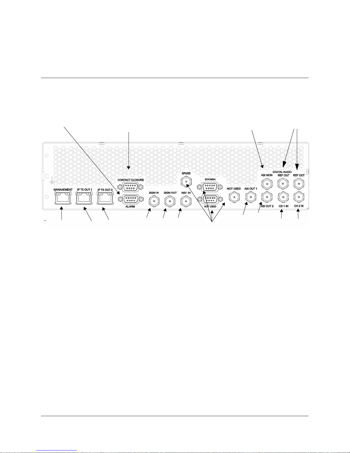
Section B - Connector Panel
Management
Audio Inputs
Alarm
Contact Closure
292M In and Out
ASI Out 1 + 2
ASI Monitor
Data Outputs
Reference
Outputs
External
Reference
Not Used
Management
Digital Audio
Alarm
Contact Closure
292M In and Out
ASI Out 1 + 2
ASI Monitor
Data Outputs
Digital Audio Inputs/
Reference Outputs
External
Reference
Not Used
Inputs
Overview
D9054 HD Encoder Connector Panel
The rear panel will appear different depending on the equipped audio
configuration; whether it is equipped with a Dual Channel Audio (DCA) card or
Multiple Channel Audio (MCA) card.
The following drawings show the two available rear connector panel
configurations:
4038938 Rev A D9054 HDTV Encoder Intstallation and Operation Guide 3-5
Dual Channel Audio (DCA) Rear Panel
Multiple Channel Audio (MCA) Rear Panel
Page 46

Rack Installation, Continued
Connectors
The following table describes the function and type of the various connectors:
Connector Function Connector Number
Power AC power. IEC 60320 Sheet 14
and Type
MANAGEMENT For control and management of local
RJ45
and remote D9054 HD Encoders.
IP TS OUT 1/IP TS
OUT 2
Data outputs for connection to an IP
distribution network.
RJ45
ALARM Alarm relays. 9-pin sub-D female
292M IN HD-SDI video input according to
BNC
SMPTE-292M.
292M OUT Active loop-through of HD-SDI
BNC
video input according to SMPTE292M.
REF IN Reference input for synchronization
BNC
to an external video source.
ASI OUT 1/ASI OUT 2 ASI output. Two identical outputs. BNC
ASI MON Monitoring of the ASI output signal.
BNC
This output signal cannot be muted.
Dual Channel Audio (with DCA card)
CH1 IN/CH2 IN Digital AES/EBU or embedded
BNC
audio inputs.
REF OUT Reference outputs to support
Multiple Channel Audio (with MCA card)
AES1/AES2 Digital AES/EBU or embedded
AES3/OUT, AES4/
OUT
3-6 D9054 HDTV Encoder Intstallation and Operation Guide 4038938 Rev A
external audio encoding. Supports
audio locked to internal video
according to SMPTE-276M.
audio inputs.
Digital AES/EBU or embedded
audio inputs, or reference outputs to
support external audio encoding.
Supports audio locked to internal
video according to SMPTE-276M.
BNC
BNC
BNC
Page 47

Section C - Connecting the Input/Output Signals
Connecting the Video Inputs
Connector for the Video Input
The video input connector is of the BNC type. The input signal is looped through to
the connector marked OUT.
The following video input signal is supported:
• 1.5 Gbit/s High Definition Serial Digital Interface (HD-SDI) according to SMPTE292M, with 1080i/25 Hz, 1080i/29.97 Hz, 720p/50 Hz or 720p/59.94 Hz.
Video Connector
The following table shows the video connector:
Connector Interface Type Connector Type
SMPTE-292M BNC female
To Connect the Video Input
1. Connect the video input signal to the connector for video, labeled 292M IN.
There are 2 connectors to provide active loop-through possibility.
2. If required, connect the 292M OUT connector to a video monitor.
To Connect the Reference Input
Do as follows to connect to the reference input:
1. Connect the reference input signal to the REF IN connector.
Use a 75-ohm double-braided coax cable.
4038938 Rev A D9054 HDTV Encoder Intstallation and Operation Guide 3-7
Page 48

Connecting the Audio Inputs
Connectors for the Audio Input
The configuration of the D9054 HD Encoder supports either two or four audio
inputs, depending on the equipped audio card. The DCA card supports two AES
inputs and two Reference outputs. The MCA card supports up to four AES inputs,
with the option to set AES3 and/or AES4 as Reference Outputs. From the GUI, you
set up the D9054 HD Encoder to use either digital AES/EBU or embedded stereo
inputs. The D9054 HD Encoder also supports encoding of audio embedded in the
HD-SDI video signal.
The following drawing shows the audio connector:
Connector Interface Type Connector Type
SMPTE-276M BNC female
Note: The digital audio output is always 75-ohm single-ended.
To Connect the Audio Inputs
Connect the audio inputs as follows:
1. Connect the audio input signals to the CH1 IN and CH2 IN BNC connectors
(with DCA configuration) or AES1 to AES4 BNC connectors (with MCA
configuration).
Use a high-quality double-shielded RJ6 coaxial cable.
3-8 D9054 HDTV Encoder Intstallation and Operation Guide 4038938 Rev A
Page 49

Connecting to the Contact Closure Interface
1
9
Contact Closure Connector
The D9054 encoder has a contact closure interface which can be used to trigger
digital program insertion (DPI). The contact closure interface has 8 inputs.
Pin Allocation
The connector labeled CONTACT CLOSURE is a 9-pin Sub-D connector (female).
The following table shows the connector and the pin allocation for the Contact
Closure connector.
Connector
Drawing
Note: Contact open = not connected (internal pull-up).
Contact closed = connected to ground.
Pin
Number
1Input 1
2Input 2
3Input 3
4Input 4
5Input 5
6Input 6
7Input 7
8Input 8
9Ground
To Connect to the Contact Closure Interface
Connect the external contact closure equipment to the contact closure interface.
Description
Configuring Open-collector outputs for the Advanced D98xx Series Receivers
The Advanced D98xx series receivers (for example, Cisco D9854 Advanced
Program Receiver and Cisco D9858 Advanced Receiver Transcoder) supports
decoding of SCTE-35 messages with DTMF descriptor.
The receiver outputs tones or sets the open collector contacts according to the
content of the DTMF descriptor. For more information on the open-collector output
settings, see Setting Up the DPI, page 5-87.
4038938 Rev A D9054 HDTV Encoder Intstallation and Operation Guide 3-9
Page 50

Connecting an External Alarm System
1
9
6 Normally Closed (Inactive)
2 Common
1 Normally Open (Active)
02-085
Connector for an External Alarm System
The D9054 HD Encoder is equipped with a connector for alarm relay outputs for
remote alarm signaling.
The Alarm output connector is a 9-pin Sub-D female connector. The following table
shows the connector and the pin allocation table for the Alarm output connector.
Connector Relay
1. Connect the cable from the external alarm system to the alarm connector.
Example, Alarm Relays
The following figure shows an example of how the alarm relays work.
For example, for an A-alarm under normal operational conditions (no alarm), pin 6
is closed, that is connected to pin 2 and pin 1 is open. However, should an alarm
condition occur pin 6 is open and pin 1 is closed, that is connected to pin 2. This
means that the A-alarm is active and the A-alarm LED lights on the front panel.
Name
Function Normally
Closed
Pin
Common
Pin
Normally
Open Pin
AA-Alarm 6 2 1
BB-Alarm 3 8 7
CC-Alarm 9 5 4
Note: The A-alarm relay is always activated when the power is off or the D9054 HD
Encoder is booting, whereas the other alarm relays maintain their status.
For example, if a B-alarm relay is inactive when the power is switched off, it stays
inactive. However, if it is active when the power is switched off, it stays active.
For information about the maximum relay load, see Alarm Interface, page A-8.
3-10 D9054 HDTV Encoder Intstallation and Operation Guide 4038938 Rev A
Page 51

Connecting the Ethernet Management Interface
18
00-052
The Ethernet Interface
The RJ-45 interface for 10/100 BASE-T Ethernet is intended for management via the
ROSA control management system.
Hint: If you experience problems with the 10 BASE-T Ethernet it is advised that
you change it to a 100 BASE-T connection.
Note: You must set up the IP address, the default gateway and the subnet mask to
match the network connection. This is done through the front panel menu. For
further information, see Front Panel Setup, page 1-3.
Pin Allocation, Ethernet Connector
The table shows the Ethernet connector and the pin allocation (MDI interface):
Connector Pin Pin Allocation
1Tx+
2Tx-
3Rx+
Informative Notes
Proper cables are required for reliable Ethernet operation; to run over a maximum
segment length of 100 m the cable has to comply with the EIA/TIA Category 5 wire
specifications. The cable must be shielded to ensure compliance with EMC
requirements.
To Connect the Ethernet Interface
1. Connect a crossed RJ-45 cable between the Ethernet connector on the D9054 HD
Encoder and the Ethernet port of your PC.
Note: You need a crossover cable if you want to connect the Ethernet interface of
the D9054 HD Encoder directly to another Ethernet device without using a hub or
switch.
4Not connected
5Not connected
6Rx-
7Not connected
8Not connected
You need to set up the IP address on both the D9054 HD Encoder (via the front
panel display) or the ROSA driver for D9054 HD Encoder. For information on
setting up the IP address via the front panel, see Front Panel Setup, page 1-3.
4038938 Rev A D9054 HDTV Encoder Intstallation and Operation Guide 3-11
Page 52

Connecting the IP TS Outputs
18
00-052
The Ethernet Interface
The RJ-45 interfaces IP TS OUT 1 and IP TS OUT 2 are 10/100 BASE-T Ethernet.
They are intended for output of the transport stream encapsulated in IP packets to
the main receiver.
Pin Allocation, Ethernet Connector
The table shows the Ethernet connector and the pin allocation (MDI interface):
Connector Pin Pin Allocation
1Tx+
2Tx-
3Rx+
4Not connected
5Not connected
6Rx-
Informative Notes
For reliable Ethernet operation; to run over a maximum segment length of 100 m
the cable has to comply with the EIA/TIA Category 5 wire specifications. The cable
must be shielded to ensure compliance with EMC requirements.
To Connect the Ethernet Interface
1. Connect a crossed RJ-45 cable between the Ethernet connector on the D9054 HD
Encoder and the Ethernet port of the equipment after the D9054 HDTV Encoder.
Note: You need a crossover cable if you want to connect the Ethernet interface of
the D9054 HD Encoder directly to another Ethernet device without using a hub or
switch.
The equipment after the D9054 HDTV Encoder could be an IP router or a switch.
7Not connected
8Not connected
3-12 D9054 HDTV Encoder Intstallation and Operation Guide 4038938 Rev A
Page 53

Connecting the ASI Outputs and the ASI Monitor
To Connect the ASI Outputs
Do as follows to connect to the ASI output:
1. Connect the output signals from the D9054 HD Encoder connectors ASI OUT 1
and/or ASI OUT2 to the ASI input connectors of the equipment after the D9054
HD Encoder.
Use a Belden “Brilliance” (or equivalent) cable with foil/braid construction. The
shield must provide 99% or better shielding effectiveness (i.e. high-quality
double-shielded RJ6 coaxial cable).
The equipment after the D9054 HD Encoder could be a Transport Stream
Multiplexer such as the Continuum DVP D9600 Re-multiplexer and Transport
Stream Processor.
Hint: The two outputs are identical and can be used for back-up purposes.
2. If you want to check the ASI output signal connect an ASI monitor to the ASI
monitor connector.
Note: The ASI monitor output cannot be muted but otherwise it works similar
to the two primary outputs.
4038938 Rev A D9054 HDTV Encoder Intstallation and Operation Guide 3-13
Page 54

3-14 D9054 HDTV Encoder Intstallation and Operation Guide 4038938 Rev A
Page 55

Overview
Introduction
This chapter describes how to set up the Cisco D9054 HDTV Encoder using the
front panel keys and display. This information is primarily applicable for
standalone operation. The only thing you need to set up via the front panel interface
is the IP address of the Cisco D9054 HDTV Encoder. In this case the rest of the
information in this chapter is for reference purposes only.
In This Chapter
This chapter contains the following topics.
Chapter 4
Front Panel Operation
Topic See Page
About the Front Panel 4-2
Keypad Convention 4-4
Startup Screen 4-5
Main Menu 4-6
PSI Menu 4-7
Video Menu 4-9
Audio Menu 4-13
Output Menu 4-22
System Menu 4-24
4038938 Rev A D9054 HDTV Encoder Installation and Operation Guide 4-1
Page 56

About the Front Panel
Numeric Keypad
Alarm LED
LCD Panel
Navigation/Selection
Power LED
Introduction
The D9054 HD Encoder is operated using controls and indicators on the front panel.
These include the numeric keypad, the Navigation/Selection keypad, the LCD, the
ALARM and POWER indicators. These are shown in the following illustration:
Keypad
LCD
The numeric keypad is used to enter alphanumeric values. The MENU key sets the
software to the initial menu and the PREV key or the UP arrow key returns to the
previous menu. The PREV key can also be used to cancel a numeric entry at any
point during the entry sequence, and the LEFT Arrow key allows backspacing
through the entry.
The LCD provides information on the selections available at any menu level,
current settings for parameters, and certain status and alarm indications. This is a
2x40, backlit LCD display. The top line may be status data or identifier information.
It can also display optional functions available for tuning operations. The bottom
line will show selections or parameter values available using the navigation/
selection keypad. The items are selected by pressing the SELECT (center key) or
DOWN Arrow key on the navigation/selection keypad.
4-2 D9054 HDTV Encoder Intstallation and Operation Guide 4038938 Rev A
Page 57

About the Front Panel, Continued
Front Panel LEDs
The function of the LEDs is described in the table below.
LED Signal Explanation Remedy
POWER Green The D9054 HD Encoder is
ALARM Red An A-alarm is active. Read the message in the GUI.
Navigation/Selection Keypad
The navigation keys (LEFT, RIGHT, UP and DOWN) and the SELECT key on this
keypad are the primary controllers. Each navigation key performs various
functions, depending on the current state of the menu system (i.e. sometimes the
left navigation key backspaces over an entry and sometimes moves the cursor to a
different menu item). Once the cursor is over the desired function, pressing the
SELECT (center key) or DOWN Arrow key selects the current item (this may go to
a different menu or change a setting). Pressing the SELECT key stores any entered
values.
N/A
correctly powered
Off There is no power present. Check the AC line supply.
Off No A-alarm is active. N/A
4038938 Rev A D9054 HDTV Encoder Intstallation and Operation Guide 4-3
Page 58

Keypad Convention
123
456
789
PREV
0
MENU
GHI
PQRS
ABC
JKL
TUV
DEF
MNO
WXYZ
F1
F2
F3
F4
Overview
Throughout this manual, there are references to parts of a keypad on
the front of the encoder. This is the Navigation/Selection keypad (see
diagram at right), which changes its function, depending on the
current state of the menu. For clarity, the following table shows which
parts of this integral interface are being referenced by which term.
When you see this… It means…
LEFT Arrow key Press the key on the left side of the
Navigation/Selection Keypad.
RIGHT Arrow key Press the key on the right side of
the Navigation/Selection Keypad.
UP Arrow key Press the key on the top of the
Navigation/Selection Keypad.
DOWN Arrow key Press the key on the bottom of the
Navigation/Selection Keypad.
SELECT key Press the key in the center of the
Navigation/Selection Keypad.
PREV key Press the key on the lower
left of the numeric
keypad
a)
.
MENU key Press the key on the lower
Alphanumeric Entry Pressing the numeric keys
F1 - F4 To be defined.
a. Numeric keypad keys are uniform. MENU and PREV have been enlarged here for effect.
4-4 D9054 HDTV Encoder Intstallation and Operation Guide 4038938 Rev A
right of the numeric
keypad
a)
.
0-9 once will enter the
respective digit into a
data entry field.
Page 59

Startup Screen
HD Encoder Model D9054
SysName ProgNo ProgName IP Addr.
Structure
On power up and initialization, an identifying startup screen displays the product
name, the system name, and the IP address of the unit.
The startup screen contains the following parameters:
SysName
Description: The Name of the system.
ProgNo
Description: The video program number. The program number is set up from
ProgName
Description: The video program name. The program name is set up from the
the GUI.
GUI.
IP Addr.
Description: The IP address of the D9054 HD Encoder. The IP address is set up
from the System menu, see IP, IP Address, page 4-24.
4038938 Rev A D9054 HDTV Encoder Intstallation and Operation Guide 4-5
Page 60

Main Menu
Main Menu
PSI Video Audio Output System Lock
04-052
Structure
Operation of the HD Encoder Model D9054 begins at the Main menu. From the
startup screen press the MENU or SELECT key to view the Main menu.
Menu Selection
Select the desired function by moving the cursor left or right by pressing the LEFT
or RIGHT key. Once a selection is made by pressing the SELECT or the DOWN key,
the LCD presents the second menu level for the selected function. Succeeding levels
for each function are described on the following pages.
4-6 D9054 HDTV Encoder Intstallation and Operation Guide 4038938 Rev A
Page 61

PSI Menu
PSI
PSI/SI Ctrl Services
Services
S1 S2 S3 S4 S5 S6 S7 S8
S1
Control Prog No PMT PID Prog Name
Structure
To see the PSI Menu, press the Menu key and then the SELECT key.
Each parameter is described below. All settings are selected and stored in the GUI.
The menu has the following structure:
PSI/SI Ctrl
Services
Services, <S1 to S8>, Control
Services, <S1 to S8>, Prog No
Services, <S1 to S8>, PMT PID
Parameters: DVB, MPEG, Disable.
Description: The status of the transmission of PSI/SI information.
Parameters: S1, S2, S3, S4, S5, S6, S7, S8.
Description: From this menu you select the audio program for which you want
to view.
Parameters: Enable, Disable.
Description: Indicates the status of the service.
Parameters: A figure between 1 and 65535.
Description: The program number of the service.
Parameters: A figure between 16 and 8190.
Description: The PMT PID assigned to the service. The default values for services
1 through 8 are 8021 to 8028 respectively.
4038938 Rev A D9054 HDTV Encoder Intstallation and Operation Guide 4-7
Page 62

PSI Menu, Continued
Services, <S1 to S8>, Prog Name
Parameters: Up to 30 alphanumeric characters.
Description: The name of the service. The supported character set is ASCII.
4-8 D9054 HDTV Encoder Intstallation and Operation Guide 4038938 Rev A
Page 63

Video Menu
Video
Input H.264 PIP/H.264 Closed Captio n
H.264
< Rate Mode CBR Rate VBR Rate >
H.264
Control Video PID GOP Chroma >
Closed Caption
Control
GOP
Dynamic GOP GOP Length B Pictures
PIP/H.264
< GOP Length Video Rate
PIP/H.264
Control Video PID Picture Size >
H.264
< SubSampling
Structure
To see the Video menu from the Main menu, press the RIGHT Arrow key and the
SELECT key.
Each parameter is described in this section. Settings are selected and stored from the
GUI.
The menu has the following structure:
Input
H.264, Control
H.264, Video PID
4038938 Rev A D9054 HDTV Encoder Intstallation and Operation Guide 4-9
Parameters: 1080i/25 Hz, 1080i/29.97 Hz, 720p/50 Hz, 720p/59.94 Hz.
Description: Indicates the video input format of the source to encode.
Parameters: Enable, Disable.
Description: Indicates the status of the video.
Parameters: A figure between 16 and 81901).
Description: The PID of the video. Observe that you may not use the same PID
for any other program element.
Page 64

Video Menu, Continued
H.264, GOP, Dynamic GOP
Parameters: Enable, Disable.
Description: Dynamic GOP should always be enabled for best video quality.
H.264, GOP, GOP Length
Parameters: A figure in the range from 1 to 255.
Description: The GOP length and the number of B-pictures influences the picture
H.264, GOP, B Pictures
Parameters: 0, 1, 2 or 3.
Dynamic GOP adds to end-to-end delay. If lower end-to-end delay
is more important than video quality, then Dynamic GOP should be
turned off (disabled).
When Dynamic GOP is on (the default is off), the encoder selects
between two hierarchical GOP structures, one with 3 B-pictures and
the other with 15 B-pictures. The selection is automatically based on
video content (scene’s spatio-temporal complexity).
When using Dynamic GOP, the GOP Length must be a multiple of
16 (i.e., 16, 32, 48, etc).
quality and delay.
Description: The GOP length and the number of B-pictures influences the picture
H.254, Chroma
Parameters: 4:2:0.
Description: You typically use 4:2:0 in distribution applications.
H.264, Rate Mode
Parameters: Variable, Fixed, Statmux.
Description: Fixed is used for constant bit rate support. Variable (Capped VBR)
quality and delay.
The following table shows example settings and their meaning:
GOP Length B Pictures Meaning
10I only
21IB
40IPPP
12 2 IBBPBBPBBPBB
is constrained to a maximum rate whereby Statmux allows you set
video bit rate (i.e., minimum and maximum) which the encoder can
operate within.
4-10 D9054 HDTV Encoder Intstallation and Operation Guide 4038938 Rev A
Page 65

Video Menu, Continued
H.264, CBR Rate
Parameters: 3,000,000 to 20,000,000 for H.264 MP@L4 for 4:2:0 chroma format.
Steps: 1 bit/s.
Description: The video bit rate for Fixed Rate Mode.
H.264, VBR Rate
Parameters: 3,000,000 to 20,000,000 for H.264 MP@L4 for 4:2:0 chroma format.
Steps: 1 bit/s.
Description: The capped video bit rate for Variable Rate Mode.
H.264, SubSampling
Parameters: Full, 3/4, 2/3 or 1/2. 2/3 horizontal resolution is not supported for
Capped variable bit rate encoding simply means that your video
channel is encoded at a variable bit rate which is capped at a specific
value. For further information, see H.264, VBR Rate, page 4-11.
3,000,000 to 25,000,000 for H.264 HP@L4 for 4:2:0 chroma format.
3,000,000 to 25,000,000 for H.264 HP@L4 for 4:2:0 chroma format.
720p.
Description: The subsampling rate.
The following table shows the lowest recommended minimum rates
with various GOP sequences at full and 3/4 horizontal
subsampling:
Video GOP
Sequence
130 22.5
220 15
315 11.25
≥4 10 7.5
The video bit rate must always be lower than the transport stream
(TS) bit rate. For further information, see Transport Stream Rates
for the Tributaries, page B-3.
Lowest Recommended Minimum
Bit Rate (Mbit/s) in Fixed Rate
Encoding
Full Horizontal
Subsampling
3/4 Horizontal
Subsampling
4038938 Rev A D9054 HDTV Encoder Intstallation and Operation Guide 4-11
Page 66

Video Menu, Continued
PIP/H.264, Control
Parameters: Off, On.
Description: Indicates the status of the video.
PIP/H.264, Video PID
Parameters: A figure between 16 and 81901).
Description: The PID of the PIP video channel. Observe that you may not use the
PIP/H.264, Picture Size
Parameters: 192x192, 128x96.
Description: Indicates the resolution of the PIP video channel.
PIP/H.264, GOP Length
Parameters: A figure in the range from 1 to 255.
Description: The GOP length and the number of B-pictures influences the picture
The following table shows example settings and their meaning:
same PID for any other program element.
quality and delay.
PIP/H.264, Video Rate
Parameters: 200,000 to 500,000, 192 x1926 resolution for 4:2:0 chroma format.
Steps: 1 bit/s.
Description: The capped video bit rate.
Closed Caption, Control
Parameters: Enable, Disable.
Description: The closed caption status.
GOP Length Meaning
1 I only
2IB
4IPPP
12 IBBPBBPBBPBB
150,000 to 500,000, 128 x 96 resolution for 4:2:0 chroma format.
4-12 D9054 HDTV Encoder Intstallation and Operation Guide 4038938 Rev A
Page 67

Audio Menu
Audio
< Linear/Dolby E AAC
Layer II
Ch1 Ch2 Ch3 Ch4 Ch5 Ch6 Ch7 Ch8
Ch1
Control Input Sample Rate Bit Rate >
Ch1
Control Input Sample Rate Data Rate >
Ch1
< Mode Audio PID
Ch1
< Mode Passthrough Audio P ID
Dolby Digital
Ch1 Ch2 Ch3 Ch4 Ch5 Ch6
AAC
Ch1 Ch2 Ch3 Ch4 Ch5 Ch6
Ch1
Control Input Sample Rate Data Rate >
Ch1
<
Mode Passthrough Audio PID
Audio
Layer II Dolby Digital >
Linear/Dolby E
Ch1 Ch2 Ch3 Ch4 Ch5 Ch6
Ch1
Control Input Mode Audio PID
Structure
To see the Audio menu from the Main menu press the RIGHT Arrow key twice and
the SELECT key.
Each parameter is described in the following. For instructions on how to select and
store settings, see About the Front Panel, page 4-2.
The menu has the following structure:
Audio
Parameters: Layer II, Dolby Digital, Linear/Dolby E, and AAC.
Description: The D9054 HD Encoder can encode the audio input according to the
4038938 Rev A D9054 HDTV Encoder Intstallation and Operation Guide 4-13
Layer II, Dolby Digital, Dolby E, and AAC standards. It also accepts
either a pre-encoded Dolby Digital input, Dolby E, or AAC input.
Page 68

Audio Menu, Continued
Layer II, <ch1 to ch12>
Parameters: Ch1 to Ch12.
Description: Select the channel you want to set up. Layer II channels Ch2 and
Layer II, <ch1 to ch12>, Control
Parameters: Enable, Disable.
Description: Enable or disable the channel in question.
Ch4 are only used in Single Mono mode, and in this case they
represent the right channels. In Single Mono mode channels Ch1,
and Ch3 represent the left mono channels.
In Stereo, Joint Stereo and Dual Channel mode, you only use
channels Ch1 and Ch3.
Note: The number of channels displayed depends on whether your
encoder is equipped with a Dual Channel Audio (DCA) card or a
Multiple Channel Audio (MCA) card. MCA cards provide six
configurable audio channels, allowing you to configure Ch 1
through Ch 12.
Layer II, <ch1 to ch12>, Input
Parameters: Digital, Embedded, Dolby-E Decoder.
Description: The D9054 HD Encoder inputs the signal from the digital input
connector in the selected format. If you select Embedded the D9054
HD Encoder extracts the audio embedded in the active SDI video
signal of the program. The packet and pair is set in the GUI.
Note: Dolby-E Decoder input type is only available if the D9054
Encoder has a Multiple Channel Audio (MCA) card that is
equipped with a Dolby Advanced Sub-Module (DASM).
Layer II, <ch1 to ch12>, Sample Rate
Parameters: 32000 Hz, 44100 Hz, 48000 Hz.
Description: The sample rate of the input signal. It doesn’t pay to increase the
encoding sample rate above that of the input sample rate.
For the lowest audio bit rates it's often recommendable to use the
lowest sample rate for best quality.
Layer II, <ch1, to ch12>, Bit Rate
Parameters: 32, 48, 56, 64, 80, 96, 112, 128, 160, 192, 224, 256, 320 or 384 (kbit/s).
Description: The bit rate must be ≤ 192 kbit/s if you set the Layer II mode to
Mono.
If you use Joint stereo it is recommended that you use bit rates up to
128 or 192 kbit/s. Joint Stereo with a bit rate of 256 or 384 kbit/s
reduces sound quality compared to stereo.
4-14 D9054 HDTV Encoder Intstallation and Operation Guide 4038938 Rev A
Page 69

Audio Menu, Continued
Layer II, <ch1 to ch12>, Mode
Parameters: Stereo, Joint Stereo, Dual Channel, Single Mono.
Description: Do not use Joint stereo audio coding if you want to transfer
matrixed sound (i.e., Dolby Surround). Use Stereo instead. If you
use Joint stereo, part of the phase information which is essential for
re-creating the surround channel information disappears.
Important: If you select the Single Mono mode, you get the setup which has been
enabled in the ROSA GUI.
Layer II, <ch1 to ch12>, Audio PID
Parameters: A figure between 16 to 8190
Description Observe that you may not use the same PID for any other program
element.
Dolby Digital, <ch1 to ch6>
Parameters: Ch1 to Ch6.
Description: Select the channel you want to set up.
Note: The number of channels displayed depends on whether your
encoder is equipped with a Dual Channel Audio (DCA) card or a
Multiple Channel Audio (MCA) card. MCA cards provide six
configurable audio channels, allowing you to configure Ch 1
through Ch 6.
1)
.
Dolby Digital, <ch1 to ch6>, Control
Parameters: Enable, Disable.
Description: Enable or disable the channel in question.
Dolby Digital, <ch1 to ch6>, Input
Parameters: Digital, Embedded, Dolby-E Decoder.
Description: The D9054 HD Encoder inputs the signal from the Digital input
connector in the selected format. If you select Embedded the D9054
HD Encoder extracts the audio embedded in the active SDI video
signal of the program. The packet and pair is set in the GUI.
Note: Dolby-E Decoder input type is only available if the D9054
Encoder has a Multiple Channel Audio (MCA) card that is
equipped with a Dolby Advanced Sub-Module (DASM).
1) Note that the DVB tables use the PIDs from 16 to 20.
4038938 Rev A D9054 HDTV Encoder Intstallation and Operation Guide 4-15
Page 70

Audio Menu, Continued
Dolby Digital, <ch1 to ch6>, Sample Rate
Parameters: 32000 Hz, 44100 Hz, 48000 Hz.
Description: The sample rate of the input signal. It doesn’t pay to increase the
encoding sample rate above that of the input sample rate.
For the lowest audio bit rates it's often recommendable to use the
lowest sample rate for best quality.
Dolby Digital, <ch1 to ch6>, Data Rate
Note: This menu will only be displayed if you have installed the
Dolby Digital audio option.
Parameters: 56, 64, 80, 96, 112, 128, 160, 192, 224, 256, 320, 384, 448, 512, 576, 640
(kbit/s).
Description: Settings for the compressed bit rate are available from 56 to 640
kbit/s. Increasing the number in this field increases the audio
bandwidth at the encoder, improving the quality of the audio
transmitted by the encoder. The default is 192 kbit/s. Use the
following data rate ranges for the selected audio mode.
Mode Data Rate Range
Stereo 2/0 96 – 640 kbit/s
Dual Mono 1+1 96 – 640 kbit/s
Mono (Center) 1/0 56 – 640 kbit/s
3/2 (L,R,C,Ls,Rs) 224 – 640 kbit/s
Note: The 3/2 (L,R,C,Ls,Rs) mode is only available for encoders
equipped with a Multiple Channel Audio (MCA) card.
4-16 D9054 HDTV Encoder Intstallation and Operation Guide 4038938 Rev A
Page 71

Audio Menu, Continued
Dolby Digital, <ch1 to ch6>, Mode
Note: This menu will only be displayed if you have installed the
Dolby Digital audio option.
Parameters: Stereo 2/0, Dual Mono 1+1, Mono 1/0, 3/2 (L,R,C,Ls,Rs).
Description: Use this setting to select the number of channels and the channel
format within the encoded bit stream.
The three available audio encoding modes are listed below. The
mode definition uses two numbers (
number of front channels, and
(surround) channels.
Stereo 2/0 Left, Right
Dual Mono 1+1 (Left – Channel 1, Right – Channel 2)
Mono (Center) 1/0 Center
3/2 (L,R,C,Ls,Rs) Left, Right, Center, Left surround, Right surround
m/n), with m indicating the
n indicating the number of rear
Mode Channel Format
The default setting is Stereo (
If the mode is set to Dual Mono (1+1), then two completely
independent program channels, referenced as Mono Channel 1 and
Mono Channel 2, are encoded into the bit stream. Dual-mono mode
is primarily intended for professional applications. Dual-mono
cannot be expected to work with consumer Dolby Digital (AC-3)
decoders.
Note: The 3/2 (L,R,C,Ls,Rs) mode is only available for encoders
equipped with a Multiple Channel Audio (MCA) card.
Note: The 3/2 (L,R,C,Ls,Rs) mode is only available for ch1 and ch4.
Dolby Digital, <ch1 to ch6>, Passthrough
Parameters: Enable, Disable.
Description From this menu you enable or disable passthrough of Dolby Digital.
The D9054 HD Encoder accepts a pre-encoded Dolby Digital audio
input. It is recommended that you set the maximum data rate to
that of the external Dolby Encoder. If the data rate of the Dolby
Encoder is lower than the setting in the D9054 HD Encoder the
audio will be passed through and only the actual bits in the data
stream will be used. The default rate is 192 kbit/s.
2/0).
4038938 Rev A D9054 HDTV Encoder Intstallation and Operation Guide 4-17
The external Dolby Encoder must be locked to the clock of the
D9054 HD Encoder. This can be achieved by connecting the Ref Out
(Reference Output) ports to the external encoder.
Page 72

Audio Menu, Continued
Dolby Digital, <ch1 to ch6>, Audio PID
Parameters: A figure between 16 to 8190
Description Observe that you may not use the same PID for any other program
element.
Linear/Dolby E, <ch1 to ch6>
Parameters: Ch1 to Ch6.
Description: Select the channel you want to set up.
Note: The number of channels displayed depends on whether your
encoder is equipped with a Dual Channel Audio (DCA) card or a
Multiple Channel Audio (MCA) card. MCA cards provide six
configurable audio channels, allowing you to configure Ch 1
through Ch 6.
Linear/Dolby E, <ch1 to ch6>, Control
Parameters: Enable, Disable.
Description: Enable or disable the selected channel.
Linear/Dolby E, <ch1 to ch6>, Input
Parameters: Digital, Embedded.
2)
.
Description: The D9054 HDTV Encoder inputs the signal from the Analog/
Digital input connector in the selected format. If you select
Embedded, the D9054 HDTV Encoder extracts the audio embedded
in the active SDI video signal of the program. The packet and pair is
set in the GUI.
Linear/Dolby E, <ch1 to ch6>, Mode
Parameters: Linear or Dolby E.
Description: Use this setting to select between Linear and Dolby E mode.
Linear/Dolby E, <ch1 to ch6>, Audio PID
Parameters: A figure between 16 to 8190.
Description Observe that you may not use the same PID for any other program
element.
2) Note that the DVB tables use the PIDs from 16 to 20.
4-18 D9054 HDTV Encoder Intstallation and Operation Guide 4038938 Rev A
Page 73

Audio Menu, Continued
AAC, <ch1 to ch6>
Parameters: Ch1 to Ch6.
Description: Select the channel you want to set up.
AAC, <ch1 to ch6>, Control
Parameters: Enable, Disable.
Description: Enable or disable the channel in question.
AAC, <ch1 to ch6>, Input
Parameters: Digital, Embedded, Dolby-E Decoder.
Description: The D9054 HD Encoder inputs the signal from the Digital input
Note: The number of channels displayed depends on whether your
encoder is equipped with a Dual Channel Audio (DCA) card or a
Multiple Channel Audio (MCA) card. MCA cards provide six
configurable audio channels, allowing you to configure Ch 1
through Ch 6.
connector in the selected format. If you select Embedded the D9054
HD Encoder extracts the audio embedded in the active SDI video
signal of the program. The packet and pair is set in the GUI.
Note: Dolby-E Decoder input type is only available if the D9054
Encoder has a Multiple Channel Audio (MCA) card that is
equipped with a Dolby Advanced Sub-Module (DASM).
AAC, <ch1 to ch6>, Sample Rate
Parameters: 32000 Hz, 44100 Hz, 48000 Hz.
Description: The sample rate of the input signal. There is no advantage to
increasing the encoding sample rate above that of the input sample
rate.
For the lowest audio bit rates it's often recommended to use the
lowest sample rate for best quality.
AAC, <ch1 to ch6>, Data Rate
Note: This menu will only be displayed if you have installed the
AAC option.
Parameters: 32, 40, 48, 56, 64, 72, 80, 96, 112, 128, 144, 160, 176, 192, 224, 256, 288,
320, 352, 382, 416, 448, 512, 576, 640 (kbit/s).
Description: Settings for the compressed bit rate are displayed in the range from
from 32 to 640 kbit/s. The default is 192 kbit/s.
4038938 Rev A D9054 HDTV Encoder Intstallation and Operation Guide 4-19
Page 74

Audio Menu, Continued
AAC, <ch1 to ch6>, Mode
Parameters: Dual Mono 1+1, Single Mono 1/0, Stereo 2/0, Joint Stereo 2/0,
Description: Do not use Joint stereo audio coding if you want to transfer
Note: This menu will only be displayed if you have installed the
AAC audio option.
Mono 1/0 LR, or 3/2 (L,C,R,Ls,Rs,LFE).
matrixed sound (i.e. Stereo Surround sound). Use Stereo instead. If
you use Joint stereo, part of the phase information which is essential
for re-creating the surround channel information disappears.
The default setting is Stereo (
If the mode is set to Dual Mono (1+1), then two completely
independent program channels, referenced as Mono Channel 1 and
Mono Channel 2, are encoded into the bit stream. Dual-mono mode
is primarily intended for professional applications. Dual-mono
cannot be expected to work with consumer AAC decoders.
Note: The 3/2 (L,C,R,Ls,Rs,LFE) mode is only available for
encoders equipped with a Multiple Channel Audio (MCA) card.
Note: The 3/2 (L,R,C,Ls,Rs) mode is only available for Ch 1 and Ch
4.
2/0).
4-20 D9054 HDTV Encoder Intstallation and Operation Guide 4038938 Rev A
Page 75

Audio Menu, Continued
AAC, <ch1 to ch6>, Passthrough
Parameters: Enable, Disable.
Description From this menu you enable or disable passthrough of AAC audio.
The D9054 HD Encoder accepts a pre-encoded AAC audio input. It
is recommended that you set the maximum data rate to that of the
external AAC Encoder. If the data rate of the AAC Encoder is lower
than the setting in the D9054 HD Encoder the audio will be passed
through and only the actual bits in the data stream will be used.
The default rate is 192 kbit/s.
The external AAC Encoder must be locked to the clock of the D9054
HD Encoder. This can be achieved by connecting the Ref Out
(Reference Output) ports to the external encoder.
AAC, <ch1 to ch6>, Audio PID
Parameters: A value between 16 to 8190
Description Observe that you may not use the same PID for any other program
element.
3)
.
3) Note that the DVB tables use the PIDs from 16 to 20.
4038938 Rev A D9054 HDTV Encoder Intstallation and Operation Guide 4-21
Page 76

Output Menu
Structure
To see the Output menu from the Main menu press the RIGHT Arrow key three
times and the SELECT key.
Each parameter is described below. The menu has the following structure:
Output Bit Rate
Parameters: 10M to 120M.
ASI Mode
Output Format
Steps: 1 bit/s.
Description: The ASI output bit rate (transport stream rate). For information
about how much the various tributaries (video, audio etc.) take up
of in the transport stream, see Transport Stream Rates for the
Tributaries, page B-3.
Parameters: Packet, Burst.
Description: In Packet mode you send a whole MPEG packet together (188/204
4)
bytes) and have stuffing in between packets. In Burst mode you
send 1 byte at a time with stuffing in between. Some non-Cisco
decoders specifically require Packet or Burst mode.
Parameters: 188, 204 RS Off.
Description: 188 means that the Reed Solomon Error Correction algorithm is not
applied on the IP TS output.
204 RS OFF. This setting only applies in a stand-alone or ROSA
controlled application. The setting means that the Reed Solomon
algorithm is not applied on the output. The 16 bytes overhead are 0
bytes which may later be used for Reed Solomon error correction.
4) 204 bytes mode is not applicable to the PNC Control System.
4-22 D9054 HDTV Encoder Intstallation and Operation Guide 4038938 Rev A
Page 77

Output Menu, Continued
IP Output
Parameters: Enable Main, Enable Backup, or IP Mode.
Description: Select Enable Main if you want to enable/disable IP data from the
IP Output, Enable Main
Parameters: Disable, Enable
Description: Select Enable to stream data to the main receiver from the IP TS
IP TS OUT 1 connector. Select Enable Backup if you want to enable/
disable IP data from the IP TS OUT 2 connector. Select IP Mode if
you want to set the mode for the eight services on the IP TS OUT 1
and IP TS OUT 2 connectors.
OUT 1 connector.
If you select Disable, there will be no output on the IP TS OUT 1
connector.
Note: You have to use the web GUI or the ROSA interface to set up
the MAC and IP addresses of the receiver of the IP streaming
packets.
IP Output, Enable Backup
Parameters: Disable, Enable.
Description: Select Enable to stream data to the backup receiver from the IP TS
IP Output, IP Mode
Parameters: S1, S2, S3, S4, S5, S6, S7, S8.
Description: Select the service.
IP Mode, <Sn>
Parameters: Disable, UDP, or RTP.
Description: For the service selected, select the IP streaming mode.
OUT 2 connector.
If you select Disable, there will be no output on the IP TS OUT 2
connector.
Note: You have to use the web GUI or the ROSA interface to set up
the MAC and IP addresses of the receiver of the IP streaming
packets.
Note: You have to use the web GUI or the ROSA interface to set up
the MAC and IP addresses of the receiver of the IP streaming
packets.
4038938 Rev A D9054 HDTV Encoder Intstallation and Operation Guide 4-23
Page 78

System Menu
System
Status IP Reset Default >
System
< Software Version Module Info >
Module Info
Main Audio1 Audio2
Option License
PNC Dolby Digital DPI PIP/H.264 >
IP
IP Address Mask Gateway Speed/Duplex
Dolby Digital
Ch1 Ch2
System
< Option License HTTP
Status
Alarms
Alarms
[A][3]LayerII: Digital Input loss
Alarms
No Alarms
HTTP
Reset Login
Option License
< AAC Statmux High Profile >
Option License
< Dolby Digital Plus Dolby-E Decoder
Structure
To see the System menu from the Main menu press the RIGHT Arrow key four
times and the SELECT key.
Each parameter is described in the following. For instructions on how to select and
store settings, see About the Front Panel, page 4-2.
The menu has the following structure:
Status, Alarms
IP, IP Address
Parameters: N/A.
Description: A list of alarms in the system. The most recent ones are displayed
first.
Parameters: <0 to 255>.<0 to 255>.<0 to 255>.<0 to 255>.
Description: The IP address of the management interface to the D9054 HD
Encoder. Contact your network administrator to obtain an IP
address.
Use the numeric keys to type the IP address.
Press the SELECT key to store the entered values.
Press the UP Arrow key to leave the menu.
When you leave the IP menu by pressing the UP Arrow once more
the IP, Mask and Gateway parameters are validated against each
other and stored. Any inconsistencies will be shown in the display.
Important: For the changes to take effect you must reset the encoder
after you have finished setting or changing the IP address, subnet
mask and default gateway. The encoder will display a reminder.
Note: The reset may take up to 90 seconds.
4-24 D9054 HDTV Encoder Intstallation and Operation Guide 4038938 Rev A
Note: The IP Address is not affected by the Default command.
Page 79

System Menu, Continued
IP, Mask
Parameters: <0 to 255>.<0 to 255>.<0 to 255>.<0 to 255>.
Description: The subnet mask of the management interface to the D9054 HD
IP, Gateway
Parameters: <0 to 255>.<0 to 255>.<0 to 255>.<0 to 255>.
Description: The default gateway of the management interface to D9054 HD
IP, Speed/Duplex
Parameters: Auto Negotiation (default), 10 Mbps Half/Full Duplex, or 100 Mbps
Encoder. Similar to the IP Address above.
Note: The subnet mask is not affected by the Default command.
Encoder. The D9054 HD Encoder uses this gateway to route IP
traffic across the network. Similar to the IP Address above.
Note: The default gateway setting is not affected by the Default
command.
Hint: The default gateway 0.0.0.0 means that no gateway is used.
Half/Full Duplex.
Reset
Description: Displays the speed/duplex of the management interface to the
D9054 HD Encoder.
Parameters: N/A.
Description: Resets (boots) the D9054 HD Encoder.
The D9054 HD Encoder displays a message asking you to confirm
the resetting of the unit. Press SELECT to reset and UP or PREV to
leave the menu without resetting.
Hint: You should reset the D9054 HD Encoder in the following
cases:
• If there has been a temperature alarm causing the D9054 HD
Encoder to disable functionality.
• If you have set or changed the IP address, subnet mask or
gateway of one of the IP interfaces of the D9054 HD Encoder via
the front panel display.
Note: The reset may take up to 90 seconds.
4038938 Rev A D9054 HDTV Encoder Intstallation and Operation Guide 4-25
Page 80

System Menu, Continued
Default
Parameters: N/A.
Description: The D9054 HD Encoder will display a message asking you to
Software Version
Parameters: N/A.
Description: The software version of the system controller.
Module Info, Main
Parameters: N/A.
Description: The hardware and the software part numbers of the main board.
Module Info, Audio1
Parameters: N/A.
Description: The hardware part number
confirm the defaulting of the unit. Press SELECT to default and UP
or PREV to leave the menu without defaulting.
Use the default settings if you have set up the D9054 HD Encoder
with illegal and incompatible settings to get the encoder back in a
functional state.
Note: The default may take up to 10 seconds.
5)
of the onboard audio module. The
audio module contains two stereo channels or 4 mono channels.
Module Info, Audio2
Parameters: N/A.
Description: The hardware part number
5) The audio module has no software part number and will show N/A in the software part
number field.
6) The audio module has no software part number and will show N/A in the software part
number field.
6)
of the optional add-on audio module.
The audio module contains two stereo channels or 4 mono
channels.
4-26 D9054 HDTV Encoder Intstallation and Operation Guide 4038938 Rev A
Page 81

System Menu, Continued
Option License, PNC
Parameters: Disabled.
Description: The status of the license signifies the following:
Option License, Dolby Digital
Parameters: Enabled, Disabled.
Description: You need an option license for each of the Dolby Digital audio
Status Explanation
Disabled The option is presently disabled (for future use).
channels. The status of the license signifies the following:
Status Explanation
Enabled The option is present and enabled.
Disabled The option is present but has been disabled. In this case
you have to enable the option to make it work.
Option License, DPI
Parameters: Enabled, Disabled.
Description: You need an option license for DPI. The status of the license
Please contact your local Cisco sales representative if you want to
buy an option.
signifies the following:
Status Explanation
Enabled The option is present and enabled.
Disabled The option is present but has been disabled. In this case
you have to enable the option to make it work.
Please contact your local Cisco sales representative if you want to
buy an option.
4038938 Rev A D9054 HDTV Encoder Intstallation and Operation Guide 4-27
Page 82

System Menu, Continued
Option License, PIP/H.264
Parameters: Enabled, Disabled.
Description: You need an option license for the PIP channel. The status of the
Option License, AAC
Parameters: Enabled, Disabled.
Description: You need an option license for each of the AAC audio channels. The
license signifies the following:
Status Explanation
Enabled The option is present and enabled.
Disabled The option is present but has been disabled. In this case
you have to enable the option to make it work.
Please contact your local Cisco sales representative if you want to
buy an option.
status of the license signifies the following:
Option License, Statmux
Parameters: Enabled, Disabled.
Description: You need an option license for Statmux. The status of the license
Status Explanation
Enabled The option is present and enabled.
Disabled The option is present but has been disabled. In this case
you have to enable the option to make it work.
Please contact your local Cisco sales representative if you want to
buy an option.
signifies the following:
Status Explanation
Enabled The option is present and enabled.
Disabled The option is present but has been disabled. In this case
you have to enable the option to make it work.
Please contact your local Cisco sales representative if you want to
buy an option.
4-28 D9054 HDTV Encoder Intstallation and Operation Guide 4038938 Rev A
Page 83

System Menu, Continued
Option License, High Profile
Parameters: Enabled, Disabled.
Description: You need an option license for High Profile. The status of the license
signifies the following:
Status Explanation
Enabled The option is present and enabled.
Disabled The option is present but has been disabled. In this case
Please contact your local Cisco sales representative if you want to
buy an option.
Option License, Dolby Digital Plus
Parameters: Enabled, Disabled.
Description: You need an option license for Dolby Digital Plus. The status of the
license signifies the following:
you have to enable the option to make it work.
Status Explanation
Enabled The option is present and enabled.
Disabled The option is present but has been disabled. In this case
Please contact your local Cisco sales representative if you want to
buy an option.
Option License, Dolby-E Decoder
Parameters: Enabled, Disabled.
Description: You need an option license for Dolby-E Decoder. The status of the
license signifies the following:
Status Explanation
Enabled The option is present and enabled.
Disabled The option is present but has been disabled. In this case
Please contact your local Cisco sales representative if you want to
buy an option.
you have to enable the option to make it work.
you have to enable the option to make it work.
4038938 Rev A D9054 HDTV Encoder Intstallation and Operation Guide 4-29
Page 84

System Menu, Continued
HTTP, Reset Login
Parameters: N/A.
Description: This resets the Web GUI password; i.e., no password will be
Note: You must reboot the encoder to enable this feature; otherwise the last
password used will be required to log on to the Web GUI.
required to log on to the Web GUI.
4-30 D9054 HDTV Encoder Intstallation and Operation Guide 4038938 Rev A
Page 85

Overview
Control Modes
You can set up and control the D9054 HDTV Encoder using the embedded Web
interface, or a PC and the ROSA management system.
Front Panel Keypad
The operation of the D9054 HDTV Encoder can be monitored using the front panel
keypad and LCD display. You can also change the IP address of the encoder using
the front panel keypad. For further information, see Front Panel Operation,
page 4-1.
Embedded Web Interface
The D9054 HDTV Encoder is delivered with an embedded web-based GUI enabling
you to set up and control the unit via an IP network.
ROSA Management
Chapter 5
Setup and Monitoring
The ROSA/Copernicus system is a multi-server/multi-client-based system
enabling you to set up and manage a complete network of encoders. In the ROSA
single-user system, the server and client are located on the same PC. Consequently
it has only one simultaneous user. ROSA enables full control and monitoring
functionality of D9054 Encoder installations and redundancy switching, error
reporting and remote control.
4038938 Rev A D9054 HDTV Encoder Installation and Operation Guide 5-1
Page 86

Overview, Continued
In This Chapter
This chapter describes how to set up and monitor the D9054 HD Encoder using the
embedded Web interface. This interface looks identical whether you are using the
embedded Web interface or the ROSA interface.
This chapter contains the following topics.
Logging On to the Web Interface 5-6
Changing the Password for the Web Interface 5-7
Web Interface - Summary Screen 5-8
Tab Pages 5-9
The Menu Bar and Buttons 5-10
Context-Sensitive Online Help 5-11
Section A - Setting Up Video 5-12
Topic See Page
Setting Up the Video Input 5-12
Setting Up the H.264 Video Encoder 5-13
3:2 Pulldown and 3:2 Pulldown Inversion 5-16
Setting Up the H.264 Video Encoding Rate 5-18
Setting Up the H.264 Video Encoding Parameters 5-18
Setting Up the H.264 PIP Video Channel 5-39
Setting Up the H.264 Video Encoder Delays 5-21
Setting Up the H.264 Aspect Ratio 5-22
Setting Up Statistical Multiplexing 5-25
Determining the Default Video Rate 5-29
Setting Up the Statistical Multiplexing Pools 5-30
Setting Up the Statistical Multiplexing Clock 5-31
Setting Up Statistical Multiplexing Quality of Service 5-32
Monitoring Statistical Multiplexing 5-35
Setting Up the H.264 PIP Video Channel 5-39
Setting Up the H.264 PIP Video Encoding Parameters 5-40
5-2 D9054 HDTV Encoder Intstallation and Operation Guide 4038938 Rev A
Page 87

Overview, Continued
Setting Up the Test Pattern 5-41
Section B - Setting Up the Pre-processor 5-42
Setting Up the Pre-processor Parameters 5-42
Setting Up the Pre-processor, Custom Filtering 5-43
Section C - Setting Up the Audio 5-44
Topic See Page
Setting Up the Layer II Audio Input
Setting Up the Layer II Channel Information
Setting Up the Layer II Test Tones
Setting Up the Dolby Digital Audio Input
Setting Up Dolby Digital Processing
Setting Up the Dolby Digital Channels
Setting Up Dolby Digital Passthrough
Setting Up Dolby Digital Test Tones
Setting Up the AAC Audio Input
Setting Up AAC Processing
Setting Up AAC Passthrough
Setting Up the AAC Test Tones
Setting Up the Linear/Dolby E Audio Input
Setting Up the Linear/Dolby E Processing
5-45
5-50
5-51
5-53
5-59
5-62
5-65
5-66
5-68
5-74
5-77
5-78
5-80
5-82
Setting Up the Linear Parameters
Setting Up the Reference Output (MCA card only)
Section E - Digital Program Insertion (DPI)
Setting Up the DPI
Section D - Setting Up the VBI 5-86
Testing and Enabling Closed Captions 5-86
Section F - Setting Up the TS Output 5-96
Setting Up the TS Output Parameters 5-96
4038938 Rev A D9054 HDTV Encoder Intstallation and Operation Guide 5-3
5-83
5-84
5-87
5-87
Page 88

Overview, Continued
Setting Up the ASI Output Parameters 5-97
Setting Up the IP Streaming Output 5-98
Section G - Setting Up the PSI 5-103
Enabling/Disabling the PSI/SI Information 5-103
Setting Up the Transport Stream 5-104
Setting Up the Service Stream 5-105
Setting Up the Video Program 5-106
Setting Up the Layer II Audio Program 5-107
Selecting the Dolby Digital Audio Descriptor Mode 5-109
Setting Up the Dolby Digital Audio Program 5-110
Setting Up the AAC Audio Program 5-112
Topic See Page
Setting Up the Linear Audio Program 5-114
Setting Up the NIT 5-116
Setting Up the Cable NIT 5-117
Setting Up the Satellite NIT 5-118
Setting Up the Terrestrial NIT 5-119
Section H - Working with the System 5-120
Reading the System Information or Managing the System 5-120
Reading the D9054 HD Encoder Temperatures 5-122
Reading the Message Status 5-123
Setting Up the Message Parameters 5-124
Viewing Messages 5-126
Viewing the Message Log 5-127
Setting Up the Trap Destinations 5-128
Removing a Trap Destination 5-130
Reading the Module Information 5-131
Setting the Date and Time Manually 5-132
5-4 D9054 HDTV Encoder Intstallation and Operation Guide 4038938 Rev A
Page 89

Overview, Continued
Setting the Clock Synchronization 5-133
Installing and Enabling Software Options 5-135
Setting Up the IP Network 5-137
Topic See Page
4038938 Rev A D9054 HDTV Encoder Intstallation and Operation Guide 5-5
Page 90

Logging On to the Web Interface
To Log on to the Web Interface
Proceed as follows to log on to the Web Interface:
1. Open MS Internet Explorer.
2. The encoder defaults to no login for the user interface.
Note: You can choose to configure the system for a user name and password
using the Logon button at the top. The new user name and password take affect
after resetting the encoder.
3. When the GUI is configured for a user name and password, type the IP address
of the D9054 HD Encoder to set up in the Address bar and press Enter.
4. Type the user name.
Hint: If you have forgotten your user name and password contact Cisco
Customer Support to have it reset.
5. Type the password.
5-6 D9054 HDTV Encoder Intstallation and Operation Guide 4038938 Rev A
Page 91

Changing the Password for the Web Interface
To Change the Password for the Web Interface
Proceed as follows to change the password for the Web Interface:
1. Log on to the Web Interface.
2. Click the Logon button at the top.
3. Type the user name and new password.
The password can be a maximum of eight ASCII characters.
Important: The password and user name will be remembered for the whole of
the web session. Close the web browser if you want to prevent others from
getting access to the settings of the D9054 HD Encoder.
Hint: If you have forgotten your Web GUI password, you can reset it from the
front panel user interface.
4. Type the new password once more.
5. Click OK.
6. Reset the D9054 HD Encoder.
You reset the D9054 HD Encoder by pressing the Reset button from the System
tab page.
4038938 Rev A D9054 HDTV Encoder Intstallation and Operation Guide 5-7
Page 92

Web Interface - Summary Screen
To get an Overview of the Main D9054 HD Encoder Settings
Proceed as follows to obtain an overview of the main D9054 HD Encoder settings:
1. Log on to the Web Interface.
2. Click the Summary tab.
The Summary shows the main settings of the D9054 HD Encoder.
5-8 D9054 HDTV Encoder Intstallation and Operation Guide 4038938 Rev A
Page 93

Tab Pages
Tab Pages
The GUI of the D9054 HD Encoder has a number of tab pages.
The function for the tab pages is as follows:
• Summary
From this page you can get an overview picture of the most important settings in
the D9054 HD Encoder.
•Video
From this page you can set up the
- video input type and resolution
- picture width, the GOP sequence, chroma format, video aspect ratio
- rate for fixed rate (CBR) encoding
- statistical multiplexing parameters such as encoding rate, statmux pools,
redundancy states and monitoring statistics
• Pre-processor
From this page you can set up the pre-analysis and noise reduction parameters.
• Audio
From this page you can set up the audio input parameters such as type,
impedance, sample rate, clipping level, audio encoding mode, bit rates.
•VBI
From this page you enable or disable the various VBI resources.
•DPI
From this page you set up the digital program insertion parameters.
•TS Output
From this page you can set up the output mode, format and bit rate. You can also
set up the parameters for the IP streaming output.
•PSI
From these tab pages you define the PIDs, program names and numbers for the
various program elements.
•System
From this tab page you an read various system parameters such as serial number,
software version number, system uptime, temperatures and slot information. You
can set up trap destinations, see messages and change message settings. You can
also install options and reboot or reset the system to the default settings.
4038938 Rev A D9054 HDTV Encoder Intstallation and Operation Guide 5-9
Page 94

The Menu Bar and Buttons
Applies All Settings in the GUI to the Encoder
Reloads All Settings into the Entire GUI
Displays the Context-Sensitive Online Help
The Help Button
The GUI of the D9054 HD Encoder has the following help button:
The Table of Contents for the online help file is displayed when you click the Help
button.
The About Button
The GUI of the D9054 HD Encoder has the following About button:
The current D9054 system version information is displayed when you click the
About button.
The Apply, Reload and Context-sensitive Help Buttons
The GUI of the D9054 HD Encoder has the following general buttons:
Note: Apply all values including the new ones are validated against each other.
Incompatible settings result in an error message telling you why the values couldn’t
be set.
5-10 D9054 HDTV Encoder Intstallation and Operation Guide 4038938 Rev A
Page 95

Context-Sensitive Online Help
Hyperlink
Table of Contents
Forwards
Backwards
Index
Table of Contents
Forwards
Backwards
Index
Online Help Features
The GUI of the D9054 HD Encoder has context-sensitive online help. Just press the
help button in the GUI and the help belonging to the current window will display.
Throughout the help system there are hypertext links to related topics.
From the help window you can:
• use the table of contents to navigate in the help system
• use the index to find specific topics
4038938 Rev A D9054 HDTV Encoder Intstallation and Operation Guide 5-11
Page 96

Section A - Setting Up Video
Setting Up the Video Input
To Set Up the Video Input
Proceed as follows to set up the Video Input:
1. From the user interface of the D9054 HD Encoder, click the Video tab.
2. Select the Video Format.
You may select 1080i/25 Hz, 1080i/29.97 Hz, 720p/50 Hz or 720p/59.94 Hz
formats.
3. Set the Frame Synchronization.
You may select Off, Internal Clock or External Reference. The default is Off.
When Off is selected, the internal frame synchronizer is bypassed. This provides
the best lip sync as the internal clock is locked to the incoming video signal.
When Internal Clock is selected, an internal reference is used as the encoding
reference. The internal clock should be used when the encoder is connected to
an unstable video source.
If the encoder is configured for an external reference, it will use an SD analog
video signal to reference its encoding reference. If the encoder is configured to
pass Dolby AC3, AAC or Dolby E/linear pre-encoded audio, it is mandatory
that the frame synchronizer be set to Off or that the external reference is locked
to the incoming video source.
4. Click Apply.
5-12 D9054 HDTV Encoder Intstallation and Operation Guide 4038938 Rev A
Page 97

Setting Up the H.264 Video Encoder
To Set Up the H.264 Video Encoder
Proceed as follows to set up the Video Encoder:
1. From the user interface of the D9054 HD Encoder, click the Video tab and then
the H.264 icon from the sub-pages.
2. Select Enable Encoder to enable the video encoder.
Disabling the video encoder means that the video program will not be encoded.
If you have defined an audio only program it will continue to be encoded.
3. Select the Chroma Format.
The chroma format is fixed at 4:2:0.
If you have problems with the video delay, see Setting Up the H.264 Video
Encoder Delays, page 5-21.
4. Select the Video Encoding Profile.
The default is Main. High Profile is also available if you purchased the High
Profile option license. High Profile provides a marginal reduction in the
required bit rate without degradation in the video quality.
4038938 Rev A D9054 HDTV Encoder Intstallation and Operation Guide 5-13
Page 98

Setting Up the H.264 Video Encoder, Continued
5. If the High Profile license is installed, and High Profile is selected as the Video
Encoding profile as shown below, all of the High Profile Features should be
enabled (checked) for optimal compression efficiency. Individual features
should only be disabled if the decoder(s) do not support the particular feature.
Note: For this application you must be using decoders downstream which
support High Profile functionality to make use of these features such as the
D9887 HDTV Modular Receiver.
Each of the High Profile settings are described below:
Intra 8x8 Prediction - selects Intra 8x8 prediction mode and 8x8 transform for
Intra-coded macroblocks in addition to Intra 16x16 and 4x4 prediction modes in
Main Profile. This increases compression efficiency.
Inter 8x8 Transform - selects 8x8 transform for Inter-coded macroblocks in
addition to 4x4 transform in Main Profile. This increases compression efficiency.
QP scaling - selects different quantization step sizes for each frequency. This
improves subjective quality at lower bit rates or for stressed content.
6. Select Full, 3/4, 2/3 or 1/2 Sub-sampling.
Subsampling decreases the resolution of the source material in order to lower
the amount of data to be encoded. 2/3 horizontal resolution is not supported for
720p.
7. Enable Dynamic GOP. Dynamic GOP should always be enabled for best video
quality.
Dynamic GOP adds to end-to-end delay. If lower end-to-end delay is more
important than video quality, then Dynamic GOP should be turned off
(disabled).
When Dynamic GOP is on (the default is off), the encoder selects between two
hierarchical GOP structures, one with 3 B-pictures and the other with 15 Bpictures. The selection is automatically based on video content (scene’s spatiotemporal complexity).
When using Dynamic GOP, the GOP Length must be a multiple of 16 (i.e., 16,
32, 48, etc).
8. Type the GOP Length.
The GOP length must be in the range from 1 to 255.
5-14 D9054 HDTV Encoder Intstallation and Operation Guide 4038938 Rev A
Page 99

Setting Up the H.264 Video Encoder, Continued
9. Type the Number of B-Pictures.
The number of B pictures must be 0, 1, 2, 3, 7 or 15.
For I-Frames only (i.e., IIII..) set GOP Length = 1 and Number of B-pictures = 0.
For IPIP..., set GOP Length = 2, Number of B-Pictures = 0.
For IPPIPP..., set GOP Length = 3, Number of B-Pictures = 0.
For typical MPEG-like GOP (i.e., IBBP...) set GOP Length = 15, Number of BPictures = 2.
10. Set the 3:2 Pulldown Inversion (abbreviated 3:2 PDI) to On if you are going to
encode 1080i/29.97 Hz material.
This improves the picture quality when encoding 1080i/29.97 Hz material that
originates from film.
Turn off the 3:2 PDI in the following instances:
Situation Reason
Your decoders are not fully MPEG2 compliant.
You need to encode all frames 3:2 PDI removes some of the frames and
The 3:2 PDI feature is only applicable for the 1080i/29.97 Hz format.
Note: Enabling 3:2 PDI increases the delay by 1 frame.
Important: Do not enable or disable 3:2 PDI during live operation. The D9054
HD Encoder restarts if you enable or disable 3:2 PDI.
11. Click Apply.
The decoders may not accept information
on picture repetition and cannot
regenerate a correct video sequence.
this means that you cannot provide full
picture-to-picture transparency from the
video input to the Transport Stream.
4038938 Rev A D9054 HDTV Encoder Intstallation and Operation Guide 5-15
Page 100

3:2 Pulldown and 3:2 Pulldown Inversion
1
1
3
2
6
5
4
7
9
8
10
1
2
2
2
3
3
4
4
4
5
5
6
6
6
7
7
8
8
8
9
9
10
10
10
1
2
23
34
4
5
6
76
87
8
9
10
1
1
2
2
3
3
4
4
5
5
6
6
7
7
8
8
9
9
10
10
Visual
appearance
Video frames
to be encoded
Source video
frames
Original film
frames
Overview
When 24 fps film is converted to 29.97 or 30 Hz HD video, the film frame rate needs
to be up-converted in order to be displayed on a TV set. This process is called 3:2
pulldown.
Basically 3:2 pulldown inversion brings back movie's original frame rate from HD’s
29.97 or 30 fps to 24 fps.
3:2 Pulldown
The 3:2 pulldown technique is used to generate video at HD frame rates from a 24
fps film source. With this technique, additional video frames are generated from the
film frames according to a characteristic, repetitive pattern.
An unwanted side-effect of this process is picture redundancy and higher load of an
encoder. The 3:2 pulldown inversion technique inverts the process and removes the
redundant frames thus increasing encoding efficiency.
3:2 Pulldown Inversion
The 3:2 PDI feature of the D9054 HD Encoder excludes the pictures of a 1080i/29.97
Hz video signal that have been duplicated through 3:2 pulldown, and allows the
D9054 HD Encoder to encode the original frames at film rate. The data in the
Transport Stream from the D9054 HD Encoder includes information on picture
repetition so that a standards-compliant decoder may output a video signal at
correct 29.97, 30, 59.94 or 60 Hz HD frame rates.
5-16 D9054 HDTV Encoder Intstallation and Operation Guide 4038938 Rev A
 Loading...