

Page 1

4020024 Rev B
Encoder Model D9040
User and Service Manual
Software Version 1.0
Page 2

Page 3

Notices
Trademark Acknowledgments
Cisco and the Cisco logo are trademarks or registered trademarks of Cisco and/or its
affiliates in the U.S. and other countries. A listing of Cisco's trademarks can be found
at www.cisco.com/go/trademarks.
Manufactured under license from Dolby Laboratories. Dolby is a registered
trademark of Dolby Laboratories.
DVB is a registered trademark of the DVB Project.
Other third party trademarks mentioned are the property of their respective owners.
The use of the word partner does not imply a partnership relationship between
Cisco and any other company. (1007R)
Publication Disclaimer
Cisco Systems, Inc. assumes no responsibility for errors or omissions that may
appear in this publication. We reserve the right to change this publication at any
time without notice. This document is not to be construed as conferring by
implication, estoppel, or otherwise any license or right under any copyright or
patent, whether or not the use of any information in this document employs an
invention claimed in any existing or later issued patent.
Copyright
© 2007-2011, 2012 Cisco and/or its affiliates. All rights reserved. Printed in the United States of
America.
Information in this publication is subject to change without notice. No part of this
publication may be reproduced or transmitted in any form, by photocopy,
microfilm, xerography, or any other means, or incorporated into any information
retrieval system, electronic or mechanical, for any purpose, without the express
permission of Cisco Systems, Inc.
AVC/MPEG-4/H.264 Products
With respect to each AVC/MPEG-4/H.264 product, Cisco is obligated to provide the
following notice:
Page 4

THIS PRODUCT IS LICENSED UNDER THE AVC PATENT PORTFOLIO LICENSE
FOR THE PERSONAL AND NON-COMMERCIAL USE OF A CONSUMER TO (i)
ENCODE VIDEO IN COMPLIANCE WITH THE AVC STANDARD ("AVC VIDEO")
AND/OR (ii) DECODE AVC VIDEO THAT WAS ENCODED BY A CONSUMER
ENGAGED IN A PERSONAL AND NON-COMMERCIAL ACTIVITY AND/OR
WAS OBTAINED FROM A VIDEO PROVIDER LICENSED TO PROVIDE AVC
VIDEO. NO LICENSE IS GRANTED OR SHALL BE IMPLIED FOR ANY OTHER
USE. ADDITIONAL INFORMATION MAY BE OBTAINED FROM MPEG LA,
L.L.C. SEE HTTP://WWW.MPEGLA.COM.
Accordingly, please be advised that service providers, content providers and
broadcasters are required to obtain a separate use license from MPEG LA prior to
any use of AVC/MPEG-4/H.264 encoders and/or decoders.
Page 5

Please Read This Entire Guide
Veuillez lire entièrement ce guide
Bitte das gesamte Handbuch durchlesen
Sírvase leer completamente la presente guía
Si prega di leggere completamente questa guida
Important:
Please read this entire guide before you install or operate this product. Give
particular attention to all safety statements.
Important:
Veuillez lire entièrement ce guide avant d'installer ou d'utiliser ce produit. Prêtez
une attention particulière à toutes les règles de sécurité.
Zu beachten:
Bitte lesen Sie vor Aufstellen oder Inbetriebnahme des Gerätes dieses Handbuch in
seiner Gesamtheit durch. Achten Sie dabei besonders auf die Sicherheitshinweise.
Importante:
Sírvase leer la presente guía antes de instalar o emplear este producto. Preste
especial atención a todos los avisos de seguridad.
Importante:
Prima di installare o usare questo prodotto si prega di leggere completamente
questa guida, facendo particolare attenzione a tutte le dichiarazioni di sicurezza.
Page 6

Page 7
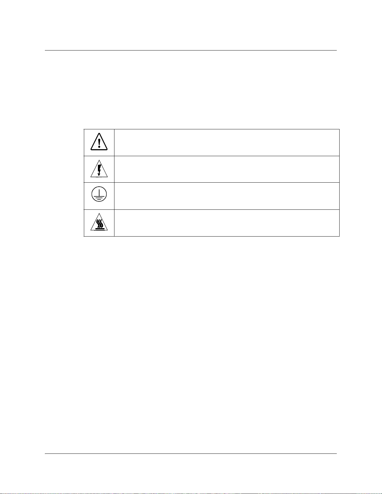
Safety Precautions
Protect yourself from electric shock and your system from damage!
• This product complies with international safety and design standards. Observe all safety
procedures that appear throughout this guide, and the safety symbols that are affixed to
this product.
• If circumstances impair the safe operation of this product, stop operation and secure this
product against further operation.
Avoid personal injury and product damage! Do not proceed beyond any symbol until
you fully understand the indicated conditions!
You may find this symbol on the product and/or in the literature that
accompanies this product.
It indicates important operating or maintenance instructions.
You may find this symbol on the product and/or in the literature that
accompanies this product.
It indicates a live terminal; the symbol pointing to the terminal device.
You may find this symbol on the product and/or in the literature that
accompanies this product.
It indicates a protective earth terminal.
You may find this symbol on the product and/or in the literature that
accompanies this product.
It indicates excessive or dangerous heat.
Power
• Important! This is a Class I product. You must earth this product.
• Connect this product only to the power source that is indicated on the back panel of this
• If this product does not have a mains power switch, the power cord serves this purpose.
Enclosure
• Do not allow moisture to enter this product.
• Do not open the enclosure of this product unless otherwise specified.
• Do not push objects through openings in the enclosure of this product.
Cables
• Always disconnect all power cables before servicing this product.
• Always pull on the plug or the connector to disconnect a cable. Never pull on the cable
• Do not walk on or place stress on cables or plugs.
Factory service
• Refer service only to service personnel who are authorized by the factory.
This product plugs into a socket-outlet. The socket-outlet must be near this product, and
must be easily accessible.
product.
itself.
4020024 Rev C iii
Page 8
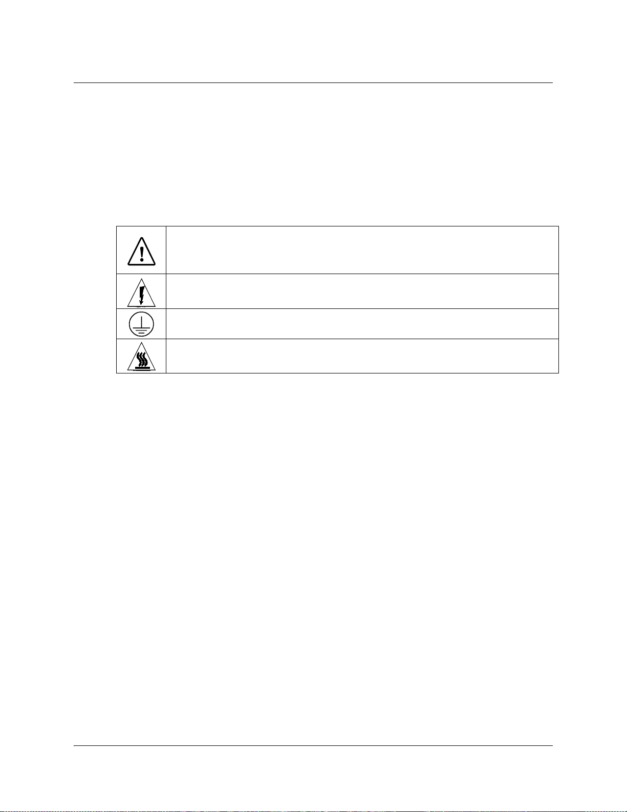
Règles de sécurité
Protégez-vous des risques d'électrocution et protégez votre système contre les
endommagements éventuels.
• Ce produit respecte les standards internationaux de sécurité et de conception. Veuillez
observer toutes les procédures de sécurité qui apparaissent dans ce guide, ainsi que les
symboles de sécurité qui figurent sur le produit.
• Si, du fait des circonstances, ce produit cesse de fonctionner normalement, cessez de
l'utiliser et empêchez-en l'utilisation future.
Évitez le risque de blessures et de dommages aux produits! Ne procédez à aucune tâche
tant que vous n'aurez pas entièrement assimilé les conditions indiquées par un symbole!
Ce symbole figure dans la documentation accompagnant ce produit. Il indique
d'importantes instructions de fonctionnement ou d'entretien.
Ce symbole peut être attaché à ce produit. Il indique une borne sous tension; la
direction indique la borne.
Ce symbole peut être attaché à ce produit. Il indique une borne de terre de
protection.
Ce symbole peut être attaché à ce produit. Il indique une température excessive ou
dangereuse.
Alimentation
• Important! Ce produit fait partie de la classe I. Vous devez le mettre à la terre.
• Ce produit se branche dans une prise murale. Cette dernière doit être placée à proximité
du produit et doit être facilement accessible.
• Ne branchez ce produit qu'à la source d'alimentation indiquée sur son panneau arrière.
• Si ce produit n'a pas d'interrupteur d'alimentation générale, le cordon d'alimentation
remplit ce rôle.
Enceinte
• Ne laissez pas l'humidité pénétrer dans ce produit.
• N'ouvrez pas l'enceinte de ce produit, sauf instructions contraires.
• Ne forcez pas d'objets dans les ouvertures du boîtier.
Câbles
• Débranchez toujours tous les cordons d'alimentation avant de réparer ce produit.
• Tirez toujours sur la prise ou le connecteur pour débrancher un câble. Ne tirez jamais
directement sur le câble.
• Ne marchez pas sur les câbles ou les prises et n'y exercez aucune pression.
Réparations effectuées à l'usine
• Ne confiez les travaux de réparations qu'au personnel autorisé par l'usine.
iv 4020024 Rev C
Page 9

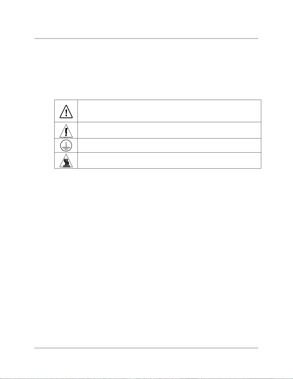
Sicherheitsvorkehrungen
Schützen Sie sich gegen elektrischen Schlag, und Ihr Gerät gegen Beschädigung!
• Dieses Gerät entspricht internationalen Sicherheits-und Ausführungsnormen. Beachten
Sie alle in diesem Handbuch enthaltenen Sicherheitshinweise sowie die am Gerät
angebrachten Warnzeichen.
• Sollten örtliche Umstände den sicheren Betrieb dieses Gerätes beeinträchtigen, schalten
Sie es ab und sichern es gegen weitere Benutzung.
Vermeiden Sie Verletzungen sowie Beschädigung des Gerätes! Wenn Sie zu einem der
folgenden Warnzeichen gelangen, nicht weiterarbeiten, bis Sie seine Bedeutung voll
verstanden haben!
Dieses Symbol erscheint auf dem Gerät und/oder in der ihm beiliegenden Literatur.
Es bedeutet wichtige, zu beachtende Betriebs-oder Wartungsanweisungen.
Wenn dieses Zeichen am Gerät angebracht ist, warnt es vor einer
spannungsführenden Stelle.
Dieses Symbol kennzeichnet auf dem Gerät die Anschlußstelle der Sicherheitserde.
Wenn dieses Zeichen am Gerät angebracht ist, warnt es vor heißen Stellen, die zu
Verbrennungen führen können.
Netzspannung
• Wichtig! Dieses Gerät ist ein Produkt der Schutzklasse I. Es muß geerdet werden.
• Das Gerät ist an einer Steckdose anzuschließen. Diese muß sich leicht zugänglich in
unmittelbarer Nähe des Gerätes befinden.
• Die Netzversorgung muß den auf der Rückwand des Gerätes angegebenen Werten
entsprechen.
• Falls sich kein Hauptschalter am Gerät befindet, dient das Netzkabel diesem Zweck.
Gehäuse
• Das Innere des Gerätes ist vor Feuchtigkeit zu schützen.
• Das Gehäuse ist nicht zu öffnen.
• Niemals einen Gegenstand durch die Gehäuseöffnungen einführen!
Kabel
• Vor jeglicher Wartung des Gerätes sind alle Kabel zu entfernen.
• Hierzu grundsätzlich am Stecker oder Verbindungsstück und niemals am Kabel selber
ziehen.
• Nicht auf die Kabel oder Stecker treten oder diese einer Zugbelastung aussetzen.
Hersteller-Wartung
Wartungsarbeiten sind nur durch vom Hersteller autorisierte Techniker vorzunehmen.
4020024 Rev C v
Page 10
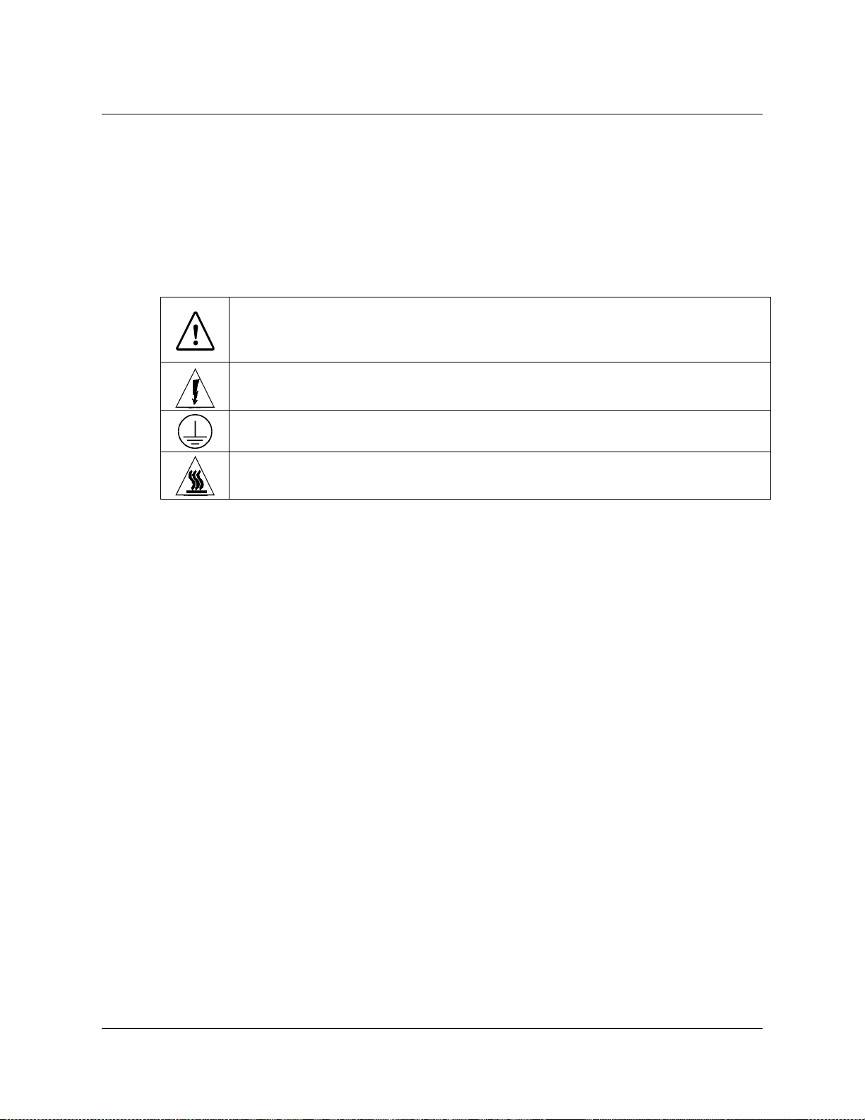
Precauciones de seguridad
¡Protéjase contra la electrocución y proteja su sistema contra los daños!
• Este producto cumple con los criterios internacionales de seguridad y diseño. Observe
todas los procedimientos de seguridad que aparecen en esta guía, y los símbolos de
seguridad adheridos a este producto.
• Si las circunstancias impiden la operación segura de este producto, suspenda la operación
y asegure este producto para que no siga funcionando.
¡Evite lastimarse y evite dañar el producto! No avance más allá de cualquier símbolo
hasta comprender completamente las condiciones indicadas!
Encontrará este símbolo en el impreso que acompaña a este producto. Este símbolo
indica instrucciones importantes de funcionamiento o mantenimiento.
Es posible que este símbolo esté pegado al producto. Este símbolo indica un terminal
vivo, la flecha apunta hacia el aparato terminal
Podría encontrar este símbolo pegado al producto. Este símbolo indica un terminal
de protección de tierra.
Podría encontrar este símbolo pegado al producto. Este símbolo indica calor
excesivo o peligroso.
Power
• Importante! Este es un producto de Clase I. Tiene que estar conectado a tierra.
• Este producto se conecta a un enchufe. El enchufe necesita estar cerca del producto y ser
fácilmente accesible.
• Conecte este producto únicamente a la fuente de suministro eléctrico indicada en el panel
posterior del producto.
• Si el producto no tiene interruptor para la linea principal, utilice el cordón toma de
corriente para este propósito.
Cubierta
• No permita que la humedad penetre en este producto.
• No abra la cubierta del producto a menos que se indique lo contrario.
• No introduzca objetos a través de las aberturas de la cubierta del producto.
Cables
• Siempre desconectar todos los cables eléctricos antes de revisar o reparar el producto.
• Tire siempre del enchufe o del conector para desconectar un cable. Nunca tire del cable
mismo.
• No camine ni aplique presión sobre los cables o enchufes.
Revisión y reparación de fábrica
Solo personal aprobado por la fábrica puede darle servicio al producto.
vi 4020024 Rev C
Page 11
Precauzioni di sicurezza
Proteggetevi da scosse elettriche e proteggete il vostro sistema da possibili danni!
• Questo prodotto soddisfa le norme internazionali per la sicurezza ed il design. Seguite
tutte le procedure di sicurezza contenute in questa guida e i simboli di sicurezza applicati
al prodotto.
• Se circostanze avverse compromettono la sicurezza d'uso di questo prodotto,
interrompetene l'uso e assicuratevi che il prodotto non venga più utilizzato.
Evitare infortuni alla persona e danni al prodotto! Non procedere oltre a qualunque
simbolo fino a quando non si siano comprese pienamente le condizioni indicate!
Questo simbolo, che appare nella letteratura di accompagnamento del prodotto,
indica importanti istruzioni d'uso e di manutenzione.
Sul prodotto potete vedere questo simbolo che indica un dispositivo terminale sotto
tensione; la freccia punta verso il dispositivo.
Potrete trovare il presente simbolo applicato a questo prodotto. Questo simbolo
indica un terminale protettivo di messa a terra.
Potrete trovare il presente simbolo attaccato a questo prodotto. Questo simbolo
indica un calore eccessivo o pericoloso.
Alimentazione
• Importante! Questo prodotto è di Classe I. Va messo a terra.
• Questo prodotto si inserisce in una presa di corrente. La presa di corrente deve essere in
prossimità del prodotto, e deve essere facilmente accessibile.
• Collegare questo prodotto solamente alla fonte di alimentazione indicata sul pannello
posteriore di questo prodotto.
• Se questo prodotto non è dotato di un interruttore principale, il cavo di alimentazione
funge a questo scopo.
Chiusura
• Proteggete da umidità questo prodotto.
• Non aprire la chiusura di questo prodotto a meno che non sia specificato diversamente.
Non inserire oggetti attraverso le fessure della chiusura.
Cavi
• Staccare sempre tutti i cavi di alimentazione prima di svolgere l'assistenza tecnica al
prodotto.
• Per scollegare un cavo tirate la spina o il connettore, non tirare mai il cavo stesso.
• Non calpestare o sottoporre a sollecitazioni i cavi o le prese.
Riparazionoi di fabbrica
• Per le riparazioni contattate solamente personale tecnico autoizzato dalla fabbrica.
4020024 Rev C vii
Page 12

Important Safety Instructions
Read and Retain Instructions
Carefully read all safety and operating instructions before operating this equipment, and
retain them for future reference.
Follow Instructions and Heed Warnings
Follow all operating and use instructions. Pay attention to all warnings and cautions in the
operating instructions, as well as those that are affixed to this equipment.
Terminology
The terms defined below are used in this document. The definitions given are based on
those found in safety standards.
Service Personnel - The term service personnel applies to trained and qualified individuals
who are allowed to install, replace, or service electrical equipment. The service personnel
are expected to use their experience and technical skills to avoid possible injury to
themselves and others due to hazards that exist in service and restricted access areas.
User and Operator - The terms user and operator apply to persons other than service
personnel, who operate this equipment..
Ground(ing) and Earth(ing) - The terms ground(ing) and earth(ing) are synonymous. This
document uses ground(ing) for clarity, but it can be interpreted as having the same meaning
as earth(ing).
Electric Shock Hazard
This equipment meets applicable safety standards.
To reduce risk of electric shock, perform only the instructions that are included in the
operating instructions. Refer all servicing to qualified service personnel only.
Electric shock can cause personal injury or even death. Avoid direct contact with dangerous
voltages at all times. The protective ground connection is essential to safe operation and
must be verified before connecting the power supply.
Know the following safety warnings and guidelines:
• Dangerous Voltages
- Only qualified service personnel are allowed to perform equipment installation or
replacement.
- Only qualified service personnel are allowed to remove chassis covers and access any
of the components inside the chassis.
• Grounding
- Do not violate the protective grounding by using an extension cable, power cable, or
autotransformer without a protective ground conductor.
- Take care to maintain the protective grounding of this equipment during service or
repair and to re-establish the protective grounding before putting this equipment back
into operation.
WARNING:
viii 4020024 Rev C
Page 13

Important Safety Instructions, Continued
Installation Site
When selecting the installation site, comply with the following:
• Protective Ground - The protective ground lead of the building's electrical installation
should comply with national and local requirements.
• Environmental Condition - The installation site should be dry, clean, and ventilated. Do
not use this equipment where it could be at risk of contact with water. Ensure that this
equipment is operated in an environment that meets the requirements as stated in this
equipment's technical specifications, which may be found on this equipment's data sheet.
Installation Requirements
WARNING:
Allow only qualified service personnel to install this equipment.
The installation must conform to all local codes and regulations.
Equipment Placement
WARNING:
Ventilation
Avoid personal injury and damage to this equipment. An unstable mounting surface
may cause this equipment to fall.
To protect against equipment damage or injury to personnel, comply with the following:
• Install this equipment in a restricted access location.
• Do not install near any heat sources such as radiators, heat registers, stoves, or other
equipment (including amplifiers) that produce heat.
• Place this equipment close enough to a mains AC outlet to accommodate the length of
this equipment's power cord.
• Route all power cords so that people cannot walk on, place objects on, or lean objects
against them. This may pinch or damage the power cords. Pay particular attention to
power cords at plugs, outlets, and the points where the power cords exit this equipment.
• Use only with a cart, stand, tripod, bracket, or table specified by the manufacturer, or sold
with this equipment.
• Make sure the mounting surface or rack is stable and can support the size and weight of
this equipment.
• The mounting surface or rack should be appropriately anchored according to
manufacturer's specifications. Ensure this equipment is securely fastened to the mounting
surface or rack where necessary to protect against damage due to any disturbance and
subsequent fall.
This equipment has openings for ventilation to protect it from overheating. To ensure
equipment reliability and safe operation, do not block or cover any of the ventilation
openings. Install the equipment in accordance with the manufacturer's instructions.
4020024 Rev C ix
Page 14
Important Safety Instructions, Continued
Rack Mounting Safety Precautions
Mechanical Loading
Make sure that the rack is placed on a stable surface. If the rack has stabilizing devices,
install these stabilizing devices before mounting any equipment in the rack.
WARNING:
Avoid personal injury and damage to this equipment. Mounting this equipment in the
rack should be such that a hazardous condition is not caused due to uneven mechanical
loading.
Reduced Airflow
When mounting this equipment in the rack, do not obstruct the cooling airflow through the
rack. Be sure to mount the blanking plates to cover unused rack space. Additional
components such as combiners and net strips should be mounted at the back of the rack, so
that the free airflow is not restricted.
CAUTION:
Installation of this equipment in a rack should be such that the amount of airflow
required for safe operation of this equipment is not compromised.
Elevated Operating Ambient Temperature
Only install this equipment in a humidity- and temperature-controlled environment that
meets the requirements given in this equipment's technical specifications.
If installed in a closed or multi-unit rack assembly, the operating ambient temperature
of the rack environment may be greater than room ambient temperature. Therefore,
install this equipment in an environment compatible with the manufacturer's
maximum rated ambient temperature.
Handling Precautions
When moving a cart that contains this equipment, check for any of the following possible
hazards:
• Use caution when moving this equipment/cart combination to avoid injury from tipover.
• If the cart does not move easily, this condition may indicate obstructions or cables that
may need to be disconnected before moving this equipment to another location.
• Avoid quick stops and starts when moving the cart.
• Check for uneven floor surfaces such as cracks or cables and cords.
CAUTION:
WARNING:
Avoid personal injury and damage to this equipment! Move any
equipment and cart combination with care. Quick stops, excessive force,
and uneven surfaces may cause this equipment and cart to overturn.
x 4020024 Rev C
Page 15

Important Safety Instructions, Continued
Grounding
This section provides instructions for verifying that the equipment is properly grounded.
Safety Plugs (USA Only)
Depending on the type and application of this equipment (Safety Class I or Safety Class II),
Cisco supplies a mains cord with either a 3-terminal (grounding-type) safety plug or a
2-terminal (polari
safety. Do not defeat the safety purpose of the grounding-type or polarized safety plug.
To properly ground this equipment, follow these safety guidelines:
• Grounding-Type Plug - For a three-terminal plug (one terminal on this plug is a
protective grounding pin), insert the plug into a grounded mains, three-terminal outlet.
Note: This plug fits only one way. If this plug cannot be fully inserted into the outlet,
contact an electrician to replace the obsolete three-terminal outlet.
• Polarized Plug - For a two-terminal plug (a polarized plug with one wide blade and one
narrow blade), insert the plug into a polarized mains, two-terminal outlet in which one
socket is wider than the other.
Note: If this plug cannot be fully inserted into the outlet, try reversing the plug. If the
plug still fails to fit, contact an electrician to replace the obsolete two-terminal outlet.
Grounding Terminal
zed) safety plug. The wide blade or the third terminal is provided for
If this equipment is equipped with an external grounding terminal, attach one end of an 18gauge wire (or larger) to the grounding terminal; then, attach the other end of the wire to a
ground, such as a grounded equipment rack.
Safety Plugs (European Union)
• Class I Mains Powered Equipment - Provided with a three-terminal AC inlet and
requires connection to a 3-terminal mains supply outlet via a three-terminal power cord
for proper connection to the protective ground.
Note: The equipotential bonding terminal provided on some equipment is not designed
to function as a protective ground connection.
• Class II Mains Powered Equipment - Provided with a two-terminal AC inlet that may be
connected by a two-terminal power cord to the mains supply outlet. No connection to the
protective ground is required as this class of equipment is provided with double or
reinforced and/or supplementary insulation in addition to the basic insulation provided
in Class I equipment.
Note: Class II equipment, which is subject to EN 50083-1, is provided with a chassis
mounted equipotential bonding terminal. See the section titled Equipotential Bonding
for connection instructions.
Equipotential Bonding
If this equipment is equipped with an external chassis terminal marked with the IEC 60417-
5020 chassis icon ( ), the installer should refer to CENELEC standard EN 50083-1 or IEC
standard IEC 60728-11 for correct equipotential bonding connection instructions.
4020024 Rev C xi
Page 16

Important Safety Instructions, Continued
AC Power
Important: If this equipment is a Class I equipment, it must be grounded.
• If this equipment plugs into an outlet, the outlet must be near this equipment, and must
be easily accessible.
• Connect this equipment only to the power sources that are identified on the equipmentrating label normally located close to the power inlet connector(s).
• If this equipment has two power sources be sure to disconnect all power sources before
working on this equipment.
• If this equipment does not have a main power switch, the power cord connector serves as
the disconnect device.
• Always pull on the plug or the connector to disconnect a cable. Never pull on the cable
itself.
• Unplug this equipment when unused for long periods of time.
Circuit Overload
Know the effects of circuit overloading before connecting this equipment to the power
supply.
CAUTION:
Consider the connection of this equipment to the supply circuit and the effect that
overloading of circuits might have on overcurrent protection and supply wiring. Refer
to the information on the equipment-rating label when addressing this concern.
General Servicing Precautions
WARNING:
Avoid electric shock! Opening or removing this equipment's cover may expose you to
dangerous voltages.
Be aware of the following general precautions and guidelines:
• Servicing - Refer all servicing to qualified service personnel. Servicing is required when
this equipment has been damaged in any way, such as power supply cord or plug is
damaged, liquid has been spilled or objects have fallen into this equipment, this
equipment has been exposed to rain or moisture, does not operate normally, or has been
dropped.
• Wristwatch and Jewelry - For personal safety and to avoid damage of this equipment
during service and repair, do not wear electrically conducting objects such as a
wristwatch or jewelry.
• Lightning - Do not work on this equipment, or connect or disconnect cables, during
periods of lightning.
• Labels - Do not remove any warning labels. Replace damaged or illegible warning labels
with new ones.
• Covers - Do not open the cover of this equipment and attempt service unless instructed to
do so in the instructions. Refer all servicing to qualified service personnel only.
• Moisture - Do not allow moisture to enter this equipment.
• Cleaning - Use a damp cloth for cleaning.
xii 4020024 Rev C
Page 17

Important Safety Instructions, Continued
• Safety Checks - After service, assemble this equipment and perform safety checks to
ensure it is safe to use before putting it back into operation.
Electrostatic Discharge
Electrostatic discharge (ESD) results from the static electricity buildup on the human body
and other objects. This static discharge can degrade components and cause failures.
Take the following precautions against electrostatic discharge:
• Use an anti-static bench mat and a wrist strap or ankle strap designed to safely ground
ESD potentials through a resistive element.
• Keep components in their anti-static packaging until installed.
• Avoid touching electronic components when installing a module.
Fuse Replacement
To replace a fuse, comply with the following:
• Disconnect the power before changing fuses.
• Identify and clear the condition that caused the original fuse failure.
• Always use a fuse of the correct type and rating. The correct type and rating are indicated
on this equipment.
Lithium Battery
For equipment with a lithium battery, observe the following rules:
• Do not dispose of used batteries through the regular garbage collection system, but follow
the local regulations. The batteries may contain substances that could be harmful to the
environment.
• Replace batteries with the same or equivalent type recommended by Cisco.
• Insert batteries correctly. There may be a risk of explosion if the batteries are incorrectly
inserted.
• When disposing of this equipment, remove the batteries and dispose of them separately
in accordance with local regulations.
• Do not recharge the batteries or expose them to temperatures above 100°C (212°F).
Electromagnetic Compatibility Regulatory Requirements
This equipment meets applicable electromagnetic compatibility (EMC) regulatory
requirements. EMC performance is dependent upon the use of correctly shielded cables of
good quality for all external connections, except the power source, when installing this
equipment.
• Ensure compliance with cable/connector specifications and associated installation
instructions where given elsewhere in this manual.
Otherwise, comply with the following good practices:
• Multi-conductor cables should be of single-braided, shielded type and have conductive
connector bodies and backshells with cable clamps that are conductively bonded to the
backshell and capable of making 360° connection to the cable shielding. Exceptions from
this general rule will be clearly stated in the connector description for the excepted
connector in question.
• Ethernet cables should be of single-shielded or double-shielded type.
• Coaxial cables should be of the double-braided shielded type.
4020024 Rev C xiii
Page 18

Important Safety Instructions, Continued
EMC
Where this equipment is subject to USA FCC and/or Industry Canada rules, the following
statements apply:
FCC Statement
This equipment has been tested and found to comply with the limits for a Class A digital
device according to Part 15 of FCC Rules. These limits are designed to provide reasonable
protection against harmful interference when this equipment is operated in a commercial
environment.
This equipment generates, uses, and can radiate radio frequency energy and, if not installed
and used in accordance with the instruction manual, may cause harmful interference to
radio communications. Operation of this equipment in a residential area is likely to cause
harmful interference in which case the user will be required to correct the interference at his
own expense.
Industry Canada - Industrie Canadienne Statement
Industry Canada ICES-003: This Class A digital apparatus meets all the requirements of the
Canadian Interference-Causing Equipment Regulations.
Industrie Canadienne ICES-003: Cet appareil numèrique de la Class A respecte toutes les
exigences du Règlement sur le matèriel brouilleur du Canada.
CENELEC/CISPR Statement with Respect to Class A Information Technology Equipment
Modifications
Accessories
This is a Class A equipment. In a domestic environment this equipment may cause radio
interference in which case the user may be required to take adequate measures.
This equipment has been designed and tested to comply with applicable safety, laser safety,
and EMC regulations, codes, and standards to ensure safe operation in its intended
environment. Refer to this equipment's data sheet for details about regulatory compliance
approvals.
Do not make modifications to this equipment. Any changes or modifications could void the
user's authority to operate this equipment.
Modifications have the potential to degrade the level of protection built into this equipment,
putting people and property at risk of injury or damage. Those persons making any
modifications expose themselves to the penalties arising from proven non-compliance with
regulatory requirements and to civil litigation for compensation in respect of consequential
damages or injury.
Use only attachments or accessories specified by the manufacturer.
xiv 4020024 Rev C
Page 19

Compliance
Electromagnetic Compatibility
FCC Part 15 Subpart B: This equipment has been tested and found to comply with the limits
for a Class A digital device, pursuant to Part 15 of the FCC Rules.
CE marked: according to EMC directive 89/336/EEC and 93/68/EEC
(European standards EN 55 022, EN 55 024, EN 61000-3-2 and EN 61000-3-3).
C-Tick marked: according to AS/NZS CISPR 22/2002.
Safety
UL listed: according to UL60950.
cUL listed: according to CSA C22.2 no. 60950.
CE marked: according to LVD directive 73/23/EEC and 93/68/EEC
(European standard EN 60950).
CB certification: according to IEC 60950.
4020024 Rev C xv
Page 20

Warranty and Disclaimer
The terms "we", "us", and "our" are used to refer to Cisco Systems, Inc. The term
"Item" is used to refer to our products (including software) provided hereunder. We
make no representations that our product is fully compatible with similarly
represented equipment from other vendors due to the wide range of
implementation possibilities of the applicable standards. We extend the following
warranty coverage to the original purchaser only, hereafter referred to as
"Purchaser". Items must be purchased from an authorized Cisco Systems, Inc.
representative or distributor.
We warrant good title to any hardware Item furnished hereunder. During the
Warranty Period (as defined below) we warrant that any hardware Item
manufactured by or for us will be free from material defects in workmanship and
materials and under ordinary use, conform in all material respects to its published
specifications current at the time the hardware Item was shipped. For a software
Item licensed by us, we warrant that we have the right to grant any software Item
license granted and that the software Item, as provided, shall substantially conform
to its published specifications current at the time the software Item was shipped.
Separately branded hardware and software Items ("Third-Party Products") are
warranted solely by the applicable manufacturer or licensor as provided below. We
will repair or replace, at our option, any Item (excluding Third-Party Products)
returned to us by Purchaser at its expense during the Warranty Period, which fails
to satisfy this Warranty, unless the failure was the result of shipping; improper
installation, maintenance or use; abnormal conditions of operation; attempted
modification or repair by the Purchaser; use of the Items in combination with other
items; or an act of God. If we elect to replace an Item, any duties, taxes, or expenses
related to the importation of the replacement Item shall be at Purchaser's expense.
The Warranty Period begins on the date the Item is originally delivered and extends
for (a) twelve (12) months for a new hardware Item manufactured by or for us, (b)
six (6) months for a remanufactured hardware Item that has been reworked by us
and is designated by us with "RMF" in the part number, and (c) ninety (90) days for
a software Item licensed by us and for parts. For Third-Party Products, we will pass
through, to the extent permitted, the manufacturer's and/or licensor's warranties
and Purchaser shall look solely to such manufacturer and/or licensor for warranty
repair. For any hardware Item that is returned to us during the Warranty Period
and which is repaired or replaced by us, the Warranty Period for such repaired or
replaced hardware Item shall be the longer of (i) the remainder of the Warranty
Period for the hardware Item, or (ii) ninety (90) days after repair or replacement of
such hardware Item by us.
xvi 4020024 Rev C
Page 21

Warranty and Disclaimer, Continued
THIS WARRANTY IS IN LIEU OF ALL OTHER WARRANTIES, EXPRESS,
IMPLIED OR STATUTORY, INCLUDING ANY WARRANTY OF
MERCHANTABILITY, FITNESS FOR A PARTICULAR PURPOSE OR
NONINFRINGEMENT. PURCHASER'S SOLE REMEDY FOR ANY BREACH OF
WARRANTY FOR HARDWARE ITEMS MANUFACTURED BY OR FOR US AND
SOFTWARE ITEMS LICENSED BY US IS THE REPAIR OR REPLACEMENT, AT
OUR OPTION, OF THE FAILED ITEM. PURCHASER'S SOLE REMEDY FOR ANY
BREACH OF WARRANTY FOR A THIRD-PARTY PRODUCT IS THE
MANUFACTURER'S WARRANTY FOR SUCH PRODUCT. WE SPECIFICALLY
DISCLAIM ANY AND ALL WARRANTIES, EXPRESS OR IMPLIED, TO
CUSTOMERS OF PURCHASER, AND ANY AND ALL WARRANTIES WITH
RESPECT TO THIRD-PARTY PRODUCTS. WE MAKE NO WARRANTY THAT
THE OPERATION OF ANY SOFTWARE ITEM WILL BE UNINTERRUPTED OR
ERROR FREE. IN ADDITION, DUE TO THE CONTINUAL DEVELOPMENT OF
NEW TECHNIQUES FOR INTRUDING UPON AND ATTACKING NETWORKS,
WE DO NOT WARRANT THAT ANY SOFTWARE ITEM OR ANY HARDWARE
ITEM ON WHICH THE SOFTWARE ITEM IS USED WILL BE FREE FROM
VULNERABILITY TO INTRUSION OR ATTACK.
EXCEPT FOR CLAIMS FOR PERSONAL INJURY CAUSED BY ITEMS OR
SERVICES FURNISHED HEREUNDER, WE SHALL NOT BE LIABLE TO
PURCHASER OR ANY OTHER PERSON OR ENTITY FOR INDIRECT, SPECIAL,
INCIDENTAL, CONSEQUENTIAL, PUNITIVE, OR EXEMPLARY DAMAGES OR
LOSS OF PROFITS ARISING OUT OF OR IN CONNECTION WITH THIS
TRANSACTION OR ANY ACTS OR OMISSIONS ASSOCIATED THEREWITH OR
RELATING TO THE SALE, LICENSE OR USE OF ANY ITEMS FURNISHED,
WHETHER SUCH CLAIM IS BASED ON BREACH OF WARRANTY,
CONTRACT, TORT OR OTHER LEGAL THEORY AND REGARDLESS OF THE
CAUSES OF SUCH LOSS OR DAMAGES, WHETHER WE WERE AWARE OF THE
POSSIBILITY OF SUCH DAMAGES, OR WHETHER ANY OTHER REMEDY
PROVIDED HEREIN FAILS. IN NO EVENT SHALL OUR TOTAL LIABILITY
HEREUNDER EXCEED AN AMOUNT EQUAL TO THE TOTAL AMOUNT PAID
FOR ITEMS PURCHASED HEREUNDER. IN NO EVENT SHALL WE BE LIABLE
TO PURCHASER FOR ANY DAMAGES RELATED TO A LICENSED SOFTWARE
ITEM IN EXCESS OF THE LESSER OF TEN THOUSAND UNITED STATES
DOLLARS (US$10,000) OR THE LICENSE FEE PAID BY PURCHASER TO US FOR
THE LICENSED SOFTWARE ITEM.
If the Purchaser returns an Item to us that is not defective under the Warranty or for
which the Warranty Period has expired, we will perform diagnostic tests on the
Item and repair the Item if it is defective. In such instances, we will be entitled to
charge the Purchaser reasonable charges for such diagnostic testing and/or repair
work.
4020024 Rev C xvii
Page 22

xviii 4020024 Rev C
Page 23

Contents
Safety Precautions ......................................................................................................................................iii
Règles de sécurité.......................................................................................................................................iv
Sicherheitsvorkehrungen ............................................................................................................................v
Precauciones de seguridad........................................................................................................................vi
Precauzioni di sicurezza............................................................................................................................vii
Important Safety Instructions.................................................................................................................. viii
Compliance.................................................................................................................................................xv
Warranty and Disclaimer ..........................................................................................................................xvi
About This Manual ................................................................................................................................. xxiii
Chapter 1 Quick Setup - Read Me First!
Connecting the Units........................................................................................................1-1
Front Panel Setup..............................................................................................................1-3
Chapter 2 Introduction
0Overview............................................................................................................................2-1
Encoder Model D9040 ......................................................................................................2-2
Application Example........................................................................................................2-6
Video Interfaces.................................................................................................................2-7
Audio and Data Interfaces...............................................................................................2-8
Transport Stream Outputs............................................................................................2-10
Control and Management Interfaces............................................................................2-11
Chapter 3 Installation
0Overview............................................................................................................................3-1
Section A - Rack Installation .................................................................................................3-2
General................................................................................................................................3-2
Installing the D9040 Encoder ..........................................................................................3-3
Section B - Connector Panel.................................................................................................3-5
Overview............................................................................................................................3-5
Section C - Connecting the Input/Output Signals ..................................................................3-7
Connecting the Video and Reference Signal Inputs ....................................................3-7
Connecting the Audio Inputs..........................................................................................3-8
4020024 Rev C xix
Page 24

Connecting to the Contact Closure or Cue Tone Interfaces......................................3-12
Connecting the Statmux Interface ................................................................................3-13
Connecting an External Alarm System........................................................................3-14
Connecting the Ethernet Management Interface........................................................3-15
Connecting the ASI Outputs and the ASI Monitor Decoder....................................3-16
Chapter 4 Front Panel Operation
0Overview............................................................................................................................4-1
About the Front Panel ......................................................................................................4-2
Keypad Convention..........................................................................................................4-4
Startup Screen....................................................................................................................4-5
Main Menu.........................................................................................................................4-6
System Menu .....................................................................................................................4-7
Lock Menu .......................................................................................................................4-14
Chapter 5 Service and Maintenance
0Overview............................................................................................................................5-1
Section A - Replacing Fans and Fuses ..................................................................................5-2
Introduction .......................................................................................................................5-2
Replacing the Fan..............................................................................................................5-3
Replacing an AC Fuse in the Power Supply .................................................................5-6
Section B - Status Signaling.................................................................................................5-7
Front Panel LEDs ..............................................................................................................5-7
Messages.............................................................................................................................5-8
Chapter 6 Customer Information
0For Information.................................................................................................................6-1
Appendix A Technical Specifications
0Overview...........................................................................................................................A-1
Section A - Video Input and Processing ...............................................................................A-2
MPEG-2 Encoder Specifications.....................................................................................A-2
Composite Video Input...................................................................................................A-3
VBI Specifications in Composite Video ........................................................................A-6
SDI Input ...........................................................................................................................A-8
Embedded Data in SDI....................................................................................................A-9
Section B - Audio Input and Processing.............................................................................A-12
Audio Input ....................................................................................................................A-12
Audio Processing ...........................................................................................................A-14
xx 4020024 Rev C
Page 25

Section C - Data Interfaces.................................................................................................A-16
Section D - Transport Stream Output .................................................................................A-17
Section E - Control and Management Interfaces.................................................................A-18
Section F - Power and General Specifications....................................................................A-20
Power ...............................................................................................................................A-20
Appendix B Equipment and Accessories
0Overview........................................................................................................................... B-1
Accessory Kits for the D9040 Encoder .......................................................................... B-2
Options and Accessories................................................................................................. B-3
Appendix C References
Applicable Documents.................................................................................................... C-1
Glossary .......................................................................................................................................Glossary-1
Index .................................................................................................................................................. Index-1
4020024 Rev C xxi
Page 26

xxii 4020024 Rev C
Page 27

About This Manual
Objective
This manual describes how to install, use and maintain the Encoder Model D9040.
Note: The manual describes all available options for the D9040 Encoder. Your
D9040 Encoder may only have some of the features described in this manual.
Audience
The audience of this manual includes users (operators) and service personnel who
are responsible for the installation, operation and service of the D9040 Encoder. For
further information about the definition of operator and service personnel, see also
the section about Service Personnel and Users and Operators in Terminology,
page viii.
Required Knowledge
To use this documentation, the user should have a basic knowledge of the
technology used in relation to this product. Service personnel should have
additional skills and be familiar with cabling, electronic circuitry, and wiring
practices.
This manual is intended for operators who are responsible for the configuration,
remote operation and maintenance of the D9040 Encoder. The operator is required
to have a basic knowledge of the PowerVu Network Centre control system.
ISO 9001
Cisco products and documentation are developed and manufactured
under the ISO 9001 Certified Quality Management System.
Related Documentation
Further helpful information is available in the following documents:
PowerVu Network Centre Control System v8.0 User’s Guide 4018881
Regulus™, Statistical Multiplex Controller User and Service
manual
Title Part No.
4006277
4020024 Rev C xxiii
Page 28

xxiv 4020024 Rev C
Page 29
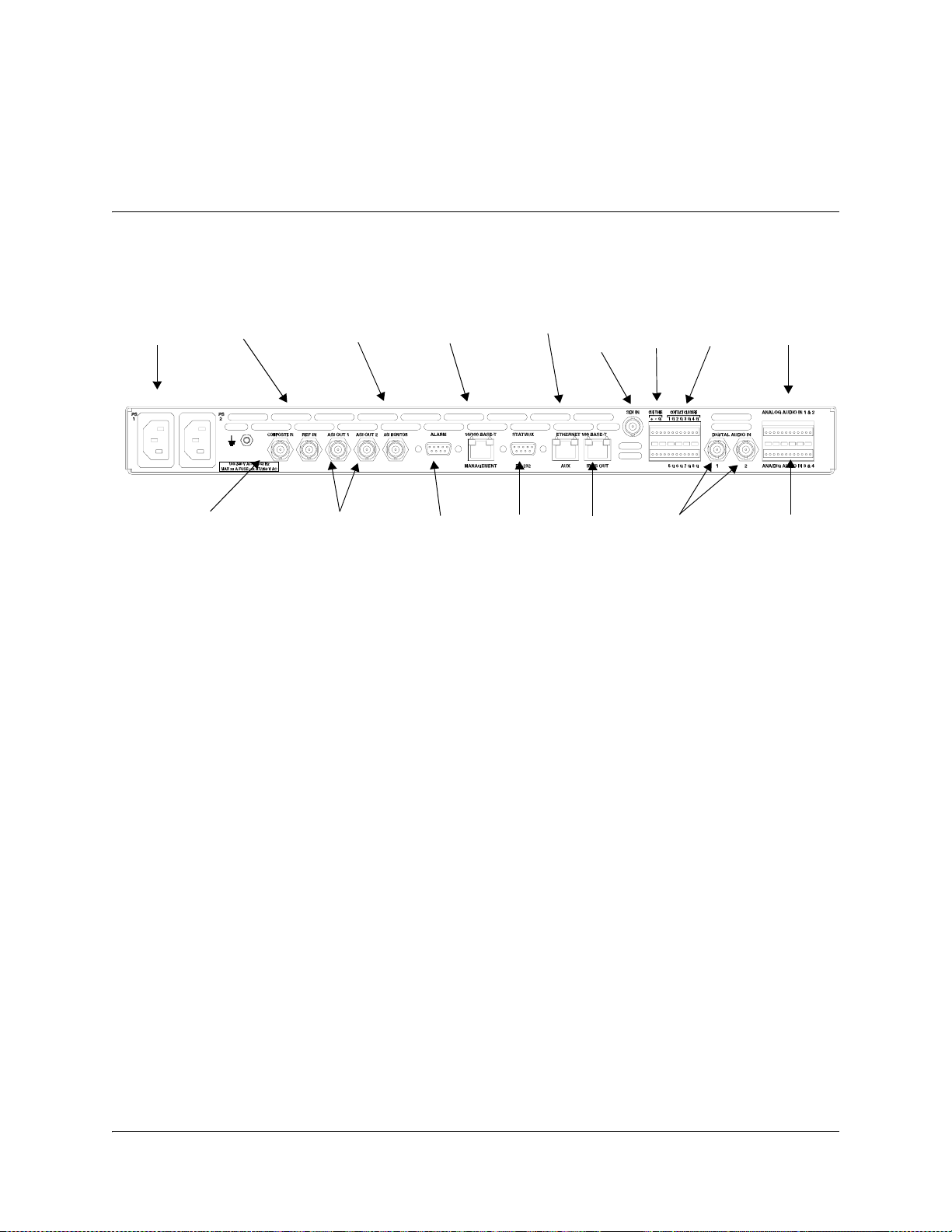
Connecting the Units
Electrical Connection
Proceed as follows to connect the units:
Chapter 1
Quick Setup - Read Me First!
AC Power
Composite Input
Reference
Input
ASI Monitor
ASI Output 1 +2
Management
Alarm
Statmux
Unused
SDI In
Unused
Cue
Tone
Digital
Audio In,
1 + 2
Contact
Closure
Analog Audio
In, 1 + 2
Analog/Digital
Audio In, 3 + 4
04-032
1. Connect the video input signal to the SDI IN and COMPOSITE IN connector.
For further information, see Connecting the Video and Reference Signal
Inputs, page 3-7.
2. If relevant, connect the reference input signal to the REF IN connector.
For further information, see To Connect the Reference Input, page 3-7.
3. Connect the audio input signals for channels 1 and 2 to the DIGITAL AUDIO IN
(2 BNC connectors) or ANALOG AUDIO IN 1+2.
Use a high-quality shielded balanced audio cable for the analog inputs or a
single-ended cable for the digital inputs. For further information, see
Connecting the Audio Inputs, page 3-8.
4. Connect the statmux interface connector of each of the D9040 Encoders to one of
the 16 statmux channel connectors of the Regulus Controller.
Use a one-to-one RS-232 cable. For further information, see Connecting the
Statmux Interface, page 3-13.
5. If relevant, connect the audio input signals for channels 3 and 4 to the terminal
block connector labelled ANA/DIG AUDIO IN 3 & 4. For further information,
see Connecting the Audio Inputs, page 3-8.
6. If relevant, connect the cable from the external alarm system to the ALARM
connector.
For further information, see Connecting an External Alarm System, page 3-14.
4020024 Rev C Quick Setup - Read Me First! 1-1
Page 30

Connecting the Units, Continued
7. If relevant, connect the external contact closure equipment or cue tone
equipment to the contact closure interface of the D9040 Encoder. For further
information, see Connecting to the Contact Closure or Cue Tone Interfaces,
page 3-12.
8. Connect the ETHERNET 10/100 BASE-T MANAGEMENT connector of the
D9040 Encoders to the Ethernet LAN of the PNC control system.
Use a shielded Cat. 5 (or better) ethernet cable. For further information, see
Connecting the Ethernet Management Interface, page 3-15.
9. Connect the output signals from the D9040 Encoder connectors ASI OUT 1 and/
or ASI OUT2 to the ASI input connectors of the equipment after the D9040
Encoder.
The equipment after the D9040 Encoder will typically be a PowerVu Model
D9140 Advanced Multiplexer.
10. If relevant, connect the output signals from the D9040 Encoder connectors ASI
MONITOR to an ASI monitor decoder.
11. Connect the power sources of all the units.
For further information, see the specific product manuals in question. When
connecting the power source to the D9040 Encoder it takes up to 120 seconds for
the unit to initialize. The front panel display shows the startup display.
1-2 Quick Setup - Read Me First! 4020024 Rev C
Page 31

Front Panel Setup
Setting Up the IP Parameters of the D9040 Encoder
Always verify that the IP parameters of the D9040 Encoder are correct before you
try to control the unit for the first time from the PNC control system. Also do as
follows when a D9040 Encoder is added to or reinserted in the installation.
Proceed as follows to set the IP settings of the D9040 Encoder, and if necessary
change them:
1. Press the MENU key on the front panel of the D9040 Encoder.
The MENU key toggles between the start up display and the main menu.
2. From the main menu press the SELECT key. You have now entered the System
menu.
3. From the System menu, press the RIGHT arrow once and the SELECT. You have
now entered the IP menu.
4. Go to the desired menu item and press the SELECT.
You use the right and left arrow keys to navigate to the desired menu item.
5. If necessary change the value.
Use the right arrow key to navigate to the digit to change and press one of the
numeric keys to enter a value. Press the SELECT key to store the entered
value(s).
6. If necessary, change the other IP parameters as described in steps 3 and 4 above.
7. Press the UP arrow to leave the IP menu.
Note: When you leave the IP menu by pressing the UP Arrow key the IP, Mask
and Gateway parameters are validated against each other and stored. Any
inconsistencies will be shown in the display.
Important: For the changes to take effect you must reset the D9040 Encoder
after you have finished setting or changing the IP address, subnet mask and
default gateway. Proceed as follows to reset the D9040 Encoder.
8. From the main menu, press the SELECT key to naviage to the System menu. You
have now entered the System menu.
9. Press the RIGHT arrow key eight times to reach the Reset menu. Press SELECT
and SELECT once more to confirm the reset.
Note: The reset make take up to 120 seconds.
4020024 Rev C Quick Setup - Read Me First! 1-3
Page 32

1-4 Quick Setup - Read Me First! 4020024 Rev C
Page 33

Overview
Introduction
This chapter is a general introduction to the Encoder Model D9040. It describes the
most common applications and interfaces of the D9040 Encoder.
In This Chapter
This chapter contains the following topics.
Chapter 2
Introduction
Topic See Page
Encoder Model D9040 2-2
Video Interfaces 2-7
Audio and Data Interfaces 2-8
Transport Stream Outputs 2-10
Control and Management Interfaces 2-11
4020024 Rev C Introduction 2-1
Page 34

Encoder Model D9040
General Description
The design of the Encoder Model D9040 is compact. The D9040 Encoder is a 1U
encoder that fits into a 19-inch rack. It features single-channel High-Definition
high-quality SDI and/or composite video processing. It is targeted at uplink
distribution and contribution applications and supports MPEG-1 Layer II audio
encoding, Dolby
audio and passthrough of AAC audio.
The D9040 Encoder features advanced pre-processing for optimum performance at
low bit rates.
PreSightPlus™ combined with the Regulus™ Statistical Multiplex Controller is one
of the industry’s leading solutions for bandwidth saving encoding.
The D9040 Encoder offers built-in support for SCTE35 digital program insertion
(DPI), which will be used for ad-insertion applications in the digital domain.
Transport output is provided via ASI outputs.
The D9040 Encoder has redundant power supplies which helps ensure
uninterrupted operation if one power supply should fail.
®
Digital (AC-3) audio, passthrough of Dolby Digital audio,AAC
Software Update
All software in the D9040 Encoder is stored in non-volatile memory that can be
electrically programmed. New software releases for the D9040 Encoder can be
downloaded via the Ethernet 10/100 Base-T Management interface.
2-2 Introduction 4020024 Rev C
Page 35

Encoder Model D9040, Continued
Software Options
The table lists the various software options which can be installed by the use of a
license key. As can be seen from the list, some of the options are pre-installed.
PNC Management
Pre-analysis
1)
VBI
1)
4:2:2
1)
DPI signalling
Statistical Multiplexing
Closed Caption
Noise Reduction
1)
1)
1)
1)
1)
Description
1. Pre-installed in all versions of the product
2. Available when ordered with 4 stereo pairs of audio (Dolby Digital or AAC
Note: All purchased options are installed and enabled at the factory.
Audio Channels
The D9040 Encoder is equipped with an SDI input and two composite inputs.
Dolby® Digital Channel 1
Dolby Digital Channel 2
Dolby Digital Channel 3
Dolby Digital Channel 4
2)
2)
Advanced Audio Coding Channel 1
Advanced Audio Coding Channel
Advanced Audio Coding Channel 3
Advanced Audio Coding Channel 4
Auto-concatenation
respectively)
1)
2)
2)
You may order the D9040 Encoder with either two or four stereo audio channels.
The audio channels may be part of the video service.
4020024 Rev C Introduction 2-3
Page 36

Encoder Model D9040, Continued
Encoding Bit Rates
Video and audio data can be encoded at the following bit rates and coding
standards:
Input signal Bit rate Coding standard
Video signal 0.5 to 15 Mbit/s MPEG-2 Main Profile at Main
Audio signal 32 to 384 kbit/s MPEG-1 Layer II
56 to 640 kbit/s Dolby Digital
1. Requires a liccnse.
VBI Signals
Level (MP@ML)
1)
Dolby Digital passthrough
1)
AAC
AAC passthrough
The following line standards are supported in three different VBI modes:
Reference Input
The D9040 Encoder provides a reference input for internal frame synchronization of
the video input to an external studio reference.
PowerVu Mode DVB-VBI Mode DVB-WST Mode
525 Lines 625 Lines 525 Lines 625 Lines 525 Lines 625 Lines
VITC VITC VITC VITC VITC
NABTS WST WST
Neilsen/
VPS
AMOL
Gemstar WSS
Transparent
2-4 Introduction 4020024 Rev C
Page 37

Encoder Model D9040, Continued
Pre-Processing
The pre-processing includes:
•PreSightPlus pre-analysis with look-ahead for improved statistical multiplexing
and normal fixed rate encoding. The PreSightPlus pre-analysis option includes
adaptive quantization m atrices which have a positive impact on both PQR values
and the subjective visual impression. The pre-analysis includes a feature to
dynamically change MPEG-2 quantization matrices and the possibility to enable
3:2 pulldown inversion for 525 lines material.
• PreSight noise reduction (low-pass spatial filter.)
The PreSight video noise reduction removes noise and details that stress the
encoder at low bit rates. It is possible to adjust the filter manually during operation
without service interruption.
The PreSightPlus video noise reduction and pre-analysis features are options that
may be ordered with the D9040 Encoder or added later.
Sub-sampling
The D9040 Encoder supports subsambling. Sub-sampling decreases the resolution
of the source material in order to lower the amount of data to be encoded.
Transport Stream
The encoded data, carrying the video and audio signals, is internally multiplexed
into the MPEG-2 and DVB compliant transport stream by the D9140 Advanced
Multiplexer. The three ASI outputs always carry the transport stream (TS).
4020024 Rev C Introduction 2-5
Page 38

Application Example
Content Distribution
The DVB-S compliant PowerVu system is designed for content distribution of high
quality services, including video, audio, data and ancillary services, over satellite.
PowerVu system users typically need to control multiple encoders in an
automatically redundant system to securely transmit services to a large receiver
population. PowerVu solutions are targeted at programmers, broadcasters, service
providers and private networks who have a particular interest in comprehensive
solutions with a focus on security. PowerVu commercial Conditional Access is an
integral part of the PowerVu offering and is controlled through the all-in-one
PowerVu Network Centre (PNC). The highly reliable PNC is a sophisticated, yet
easy-to-use system that can provide network management, security, decoder
management, and advanced revenue protection. In addition to the PNC, a PowerVu
system can also support a number of IRDs to meet specific customer needs.
The Regulus™ Statistical Multiplex Controller is an add-on unit for the D9040
Encoder. You may connect the Regulus Controller to a number of encoders so that
they together may participate in statistical multiplexing.
ideo
ideo
ideo
ideo
REGULUS Statistical Multiplex Controller
1 2 3 5 6 87 9
Regulus Controller
D9040 Encoder
D9040 Encoder
D9050 Encoder
D9050 Encoder
CHANNEL STATUS
4
POWER
ALARM
1110 12 1413 15
16
FAILURE
Power Vu®
HD Encoder
Power Vu®
HD Encoder
TS output
TS output
Power Vu®
Power Vu®
HD Encoder
HD Encoder
Power Vu®
Power Vu®
HD Encoder
HD Encoder
D9140 Advanced Multiplexer
D9140 Advanced Multiplexer
PowerVu
Networ k
Centre
(PNC)
Ethernet Hub
Satellite
Satellite Dish
1 2 3
TM
PowerVu
ALARM
4 5 6
SELECT
7 8 9
POWER
PREV 0 MENU
D9390,
D9390,
1 2 3
TM
PowerVu
4 5 6
ALARM
SELECT
7 8 9
POWER
PREV0MENU
TM
BitMizer
TM
BitMizer
D9390 Advanced
Standalone Modulator
D9390 Advanced
Standalone Modulator
Satellite Dish
1 2 3
4 5 6
ALARM
SELECT
7 8 9
POWER
DVB
PREV0MENU
D9850 Program Receiver
1 2 3
ALARM
4 5 6
SELECT
7 8 9
POWER
DVB
PREV0MENU
D9850 Program Receiver
1 2 3
4 5 6
ALARM
SELECT
7 8 9
POWER
DVB
PREV0MENU
TM
PowerVu
Program Receiver
D9850
TM
PowerVu
Program Receiver
D9850
TM
PowerVu
Program Receiver
D9850
D9850 Program Receiver
1 2 3
TM
PowerVu
ALARM
4 5 6
Program Receiver
SELECT
D9850
7 8 9
POWER
DVB
PREV0MENU
D9850 Program Receiver
2-6 Introduction 4020024 Rev C
Page 39

Video Interfaces
Composite Video Input
The composite video input interface accepts a 625-line PAL (B, D, G, H, I, K, M and
N) or 525-line NTSC (M)or J-NTSC (for Japan) formatted input signal.
SDI Video Input
The SDI input interface accepts a 270 Mbit/s SDI formatted video input (D-1). The
SDI module extracts embedded audio for further processing by an audio encoder
module.
VBI and Related Signals
The D9040 Encoder supports teletext B, DVB-VBI Teletext, Transparent Lines, VPS,
WSS, VII and Closed Captioning.
Encoding
The video encoding includes:
• Multiple resolutions
• High quality also at very low bit rates
The AFD feature requires that you have installed the VBI option.
Auto-concatenation
The D9040 Encoder optionally supports auto-concatenation of previously encoded
picture material. Auto-concatenation makes it possible to align I-frames of encoded
pictures with I-frames of previously encoded input material. By detecting the
position of I-frames in the incoming video and making proper adjustments to the
GOP, the I-frames of the encoded material can be aligned to the input. The GOP
adjustments are performed seamlessly.
This feature decreases the degradation of video quality usually seen when two or
more encoders are cascaded (concatenated).
4020024 Rev C Introduction 2-7
Page 40

Audio and Data Interfaces
Audio Input
Four audio stereo channels can be input at the D9040 Encoder. Each of the audio
channels can be sourced from analog, digital AES-3id or embedded SDI audio
sources. You can assign the encoded audio channels to the video program or to
independent audio only programs.
Digital Audio Interface
The audio input interface accepts a digital input, formatted as an AES/EBU
encoded signal. Left and right channel samples are extracted from the input and
synchronized to the video signal.
Analog Audio Interface
The audio input interface features balanced left and right analog inputs. For each
analog audio input you can set the input impedance and the clipping level.
Embedded Audio
The audio input interface can be configured to accept an input of embedded audio
from the SDI video input interface.
Audio Encoding Formats
The supported audio encoding formats are MPEG-1 layer II, Dolby Digital,
passthrough of Dolby Digital, andAAC.
Layer II Encoding
The audio inputs may be encoded in the following ways:
• a stereo program
• a joint stereo program
• two independent mono programs
• Dual channel
You can set the sampling frequency for the digitizing process to one of the
following values:
•32 kHz
• 44.1 kHz
•48 kHz.
For audio attached to the video the D9040 Encoder locks the audio sampling
frequency to the video. For AES/EBU digital input signals, the D9040 Encoder
automatically adapts the incoming rate by using sample rate conversion.
2-8 Introduction 4020024 Rev C
Page 41

Audio and Data Interfaces, Continued
Dolby Digital Encoding
The audio inputs may be encoded in the following ways:
•Dual Mono 1+1
•Stereo 2/0
•Mono 1/0
You can set the sampling frequency for the digitizing process to one of the
following values:
•32 kHz
• 44.1 kHz
•48 kHz.
The D9040 Encoder locks the audio sampling frequency to the video. For AES/EBU
digital input signals, the D9040 Encoder automatically adapts the incoming rate by
using sample rate conversion.
Dolby Digital Passthrough
The D9040 Encoder supports passthrough of up to four pre-encoded Dolby Digital
stereo channels.
AAC Encoding
The audio inputs may be encoded in the following ways:
•Dual Mono 1+1,
• Single Mono 1/0,
•Stereo 2/0,
• Joint Stereo 2/0,
•Mono 1/0 LR
You can set the sampling frequency for the digitizing process to one of the
following values:
•32 kHz
• 44.1 kHz
•48 kHz.
The D9040 Encoder locks the audio sampling frequency to the video. For AES/EBU
digital input signals, the D9040 Encoder automatically adapts the incoming rate by
using sample rate conversion.
AAC Passthrough.
The D9040 Encoder supports passthrough of up to four pre-encoded AAC channels.
Audio Only
The D9040 Encoder supports up to eight mono or four stereo audio only programs.
One or more audio sources can be combined to make up a program.
4020024 Rev C Introduction 2-9
Page 42

Transport Stream Outputs
DVB-ASI Transport Stream Output
The D9040 Encoder has three DVB-ASI outputs. These outputs can be used as an
input for a satellite modem or a multiplexer. One of the outputs is an ASI monitor
output for monitoring of the outgoing data stream. Unlike the two other ASI
outputs the monitor output cannot be muted.
The outputs support SI generation with standard tables compliant to MPEG-2 and
DVB.
2-10 Introduction 4020024 Rev C
Page 43

Control and Management Interfaces
PNC Control System Management
The PNC is a single-server/multi-client based system enabling you to set up and
manage a whole network of encoders. In the PNC multi-user system, the server and
client are located on separate PCs. The PNC enables full control and monitoring
functionality of the D9040 Encoder installations with redundancy switching, error
reporting and remote control. Refer to the PowerVu Network Centre Control
System v8.0 User’s Guide (part number 4018881 Rev A) for more information.
Front Panel Control
There is limited control available via the front panel. You can only set or change the
encoder IP address, lock or unlock the front panel, and monitor the alarm status.
The following drawing shows the front panel with its different sections.
Ethernet
LCD Panel
Alarm LED
Power LED
Navigation/
Selection Keypad
Numeric Keypad
The main control interface for the D9040 Encoder is the 10/100 BaseT Ethernet
interface.
You can set up and control the D9040 Encoder via the Ethernet connection using
SNMP and the PNC control system.
4020024 Rev C Introduction 2-11
Page 44

Control and Management Interfaces, Continued
Alarm Relay Interface
During operation the condition of the D9040 Encoder can be monitored by three
relay contact outputs, accessible from the Alarm connector on the rear panel of the
D9040 Encoder. Furthermore, the alarm status is signalled by Alarm LEDs on the
front of the D9040 Encoder and by messages sent via the PNC control system. Refer
to Connecting an External Alarm System, page 3-14 for more information.
DPI and Cue Trigger Interfaces
The contact closure and cue trigger interfaces are used to signal cue triggers and
trigger Digital Program Insertion (DPI). DPI allows for the insertion of
advertisements into program content in the digital domain. The DPI messages are
in accordance with the SCTE 35 specification.
Redundancy
Encoder redundancy is controlled by the PNC.
2-12 Introduction 4020024 Rev C
Page 45

Overview
Introduction
This chapter describes how to install the Encoder Model D9040. Before installing the
D9040 Encoder, read all safety precautions and guidelines thoroughly.
Qualified Personnel
Only appropriately qualified and trained service personnel or operators should
attempt to install, operate or maintain the D9040 Encoder.
Allow only qualified service personnel to install this product. Otherwise,
personal injury or equipment damage may occur.
In This Chapter
Chapter 3
Installation
WARNING:
This chapter contains the following topics.
Topic See Page
Section A - Rack Installation 3-2
General 3-2
Section B - Connector Panel 3-5
Overview 3-5
Section C - Connecting the Input/Output Signals 3-7
Connecting the Video and Reference Signal Inputs 3-7
Connecting the Audio Inputs 3-8
Connecting to the Contact Closure or Cue Tone Interfaces 3-12
Connecting the Statmux Interface 3-13
Connecting an External Alarm System 3-14
Connecting the Ethernet Management Interface 3-15
Connecting the ASI Outputs and the ASI Monitor Decoder 3-16
4020024 Rev C Installation 3-1
Page 46

General
Power Connection
As Cisco units are designed for 24-hour operation, some products do not have a
power switch. In this case, the mains cord serves as the mains disconnect
device.
Make sure that at least one end of the power cables remains easily accessible
for unplugging, if you need to switch off the unit. For example: Ensure that the
socket outlet is installed near the product.
Section A - Rack Installation
WARNING:
3-2 Installation 4020024 Rev C
Page 47

Installing the D9040 Encoder
Rack Mounted
The D9040 Encoder is a 1U unit with connector access at the rear panel. The D9040
Encoder is intended for mounting in a standard 19" rack.
Cooling
The D9040 Encoder is cooled by the use of fans. The air intake is from the front
panel and the air outlet is on the rear.
CAUTION:
The inlet air temperature must not exceed 50 °C/122 °F at any time.
Grounding
You must ensure that the unit is properly connected to ground in order to meet
safety and EMC requirements. Before any other connection is made, the unit must
be connected to a protected ground terminal as described below:
• Via the three wire power cord of the AC power supply. This connection is
mandatory.
• In addition, via the protective ground terminal on the rear panel of the unit. This
connection provides additional protection of the equipment.
To Mount the D9040 Encoder
To mount the D9040 Encoder in a rack do the following:
1. Mount rails in the rack to support each D9040 Encoder to be installed.
For further information, contact your rack supplier.
2. Place the D9040 Encoder in its position in the rack.
3. Mount the D9040 Encoder securely to the rack by securing four screws in the
holes in the front panel mounting flanges.
4. Make sure that air can circulate freely from the front of D9040 Encoder.
5. Do not block the air outlet holes on the back of the D9040 Encoder.
4020024 Rev C Installation 3-3
Page 48

Installing the D9040 Encoder, Continued
To Connect AC Power
To connect AC power to the D9040 Encoder do the following:
1. Connect the power cords(supplied with the D9040 Encoder) between the rear
panel power receptacles and an 100 to 240 V AC power outlet.
2. Make sure that the power cables are connected to protective ground.
See Grounding at the beginning of this section.
3-4 Installation 4020024 Rev C
Page 49

Section B - Connector Panel
Overview
D9040 Encoder Connector Panel
The following drawing shows the rear connector panel of the D9040 Encoder.
AC Power
Composite Input
Reference
Input
ASI Monitor
ASI Output 1 +2
Management
Alarm
Statmux
Unused
SDI In
Unused
Cue
Tone
Digital
Audio In,
1 + 2
Contact
Closure
Analog Audio
In, 1 + 2
Analog/Digital
Audio In, 3 + 4
04-032
4020024 Rev C Installation 3-5
Page 50

Overview, Continued
Connectors
The following table describes the function and type of the various connectors:
Connector Function Connector Number
Power AC power IEC 60320 Sheet 14
COMPOSITE IN Composite input (PAL/NTSC) BNC
and Type
REF IN Reference input for synchronization
to an external video source.
ASI OUT 1
ASI OUT 2
ASI Monitor ASI output. This output cannot be
ALARM Alarm relays 9-pin sub-D female
10/100 BASE-T
MANAGEMENT
STATMUX Connection to the Regulus Statistical
ETHERNET 100
BASE-T AUX
ETHERNET 100
BASE-T IP TS OUT
SDI IN SDI input BNC
ASI output. Two identical outputs.
Outputs can be muted.
muted.
For control and management of local
and remote D9040 Encoder units.
Multiplex Controller
Transport stream encapsulated in IP
packets. Used for Backup IP output
or PCR synchronization
Transport stream encapsulated in IP
packets. Used for Main IP output
BNC
BNC
BNC
RJ45
9-pin sub-D female
RJ45
RJ45
CUE TONE
CONTACT
CLOSURE
DIGITAL AUDIO IN
(1 + 2)
ANALOG AUDIO
IN 1 & 2
ANA/DIG AUDIO
IN 3 + 4
3-6 Installation 4020024 Rev C
Cue tones for DPI triggering (not
supported in this release)
Contact closure for DPI triggering
Audio mode changes
Digital audio input for channels 1
and 2
Analog audio input for channels 1
and 2
Analog and digital audio input for
channels 3 and 4
Terminal block
75 ohm
Terminal block
Terminal block - 75
ohm or 110 ohm
Page 51

Section C - Connecting the Input/Output Signals
Connecting the Video and Reference Signal Inputs
Connectors for the Video and Reference Signal Inputs
Both the SDI, composite video input and reference input connectors are of the BNC
type and are internally terminated.
The following video and reference input signals are supported:
• 270 Mbit/s digital 525 and 625 lines SDI, or
• Analog composite PAL (B, D, G, H, I , K, M, N) , NTSC system M and J-NTSC
• Composite reference input
To Connect to the Video Input
Do as follows to connect to the video input:
1. Connect the video input signal to the SDI In or Composite In connector.
Use a 75-ohm double-braided coax cable.
To Connect the Reference Input
Do as follows to connect to the reference input:
1. Connect the reference input signal to the REF IN connector.
Use a 75-ohm double-braided coax cable.
4020024 Rev C Installation 3-7
Page 52

Connecting the Audio Inputs
Connectors for the Audio Input
The basic configuration of the D9040 Encoder supports two stereo channels.
Optionally it supports two additional stereo channels.
Digital audio for channels 1 and 2 is input at the BNC connector called Digital
Audio In.
The following drawing shows the two BNC connectors:
The connector label Analog Audio In 1 & 2 denotes that analog audio for channels 1
and 2 is input at the top row of pins on the terminal block connector.
The connector label Ana/Dig Audio In 3 & 4 denotes that analog or digital audio for
channels 3 and 4 is input at the bottom row of pins on the terminal block connector.
On the PNC, you can set up the D9040 Encoder to use either the analog or the
digital stereo channels. The D9040 Encoder also supports encoding of audio
embedded in the SDI video signal.
The following drawing shows the pin positions of the terminal block connector:
3-8 Installation 4020024 Rev C
Page 53

Connecting the Audio Inputs, Continued
The pinout for the analog part of the terminal block connector is as follows:
Channel
Numbering
Pin
Number
Layer IIDolby
Digital
111
Analog
Type Signal
Analog InLeft +
2
3
421
Analog InRight +
5
6
732
Analog InLeft +
8
9
10 4 2
Analog InRight +
11
Left -
Shield
Right -
Shield
Left -
Shield
Right -
12
13 5 3
14
15
16 6 3
17
18
19 7 4
20
21
22 8 4
23
24
Shield
Analog InLeft +
Left -
Shield
Analog Right +
Right -
Shield
Analog Left +
Left -
Shield
Analog Right +
Right -
Shield
4020024 Rev C Installation 3-9
Page 54
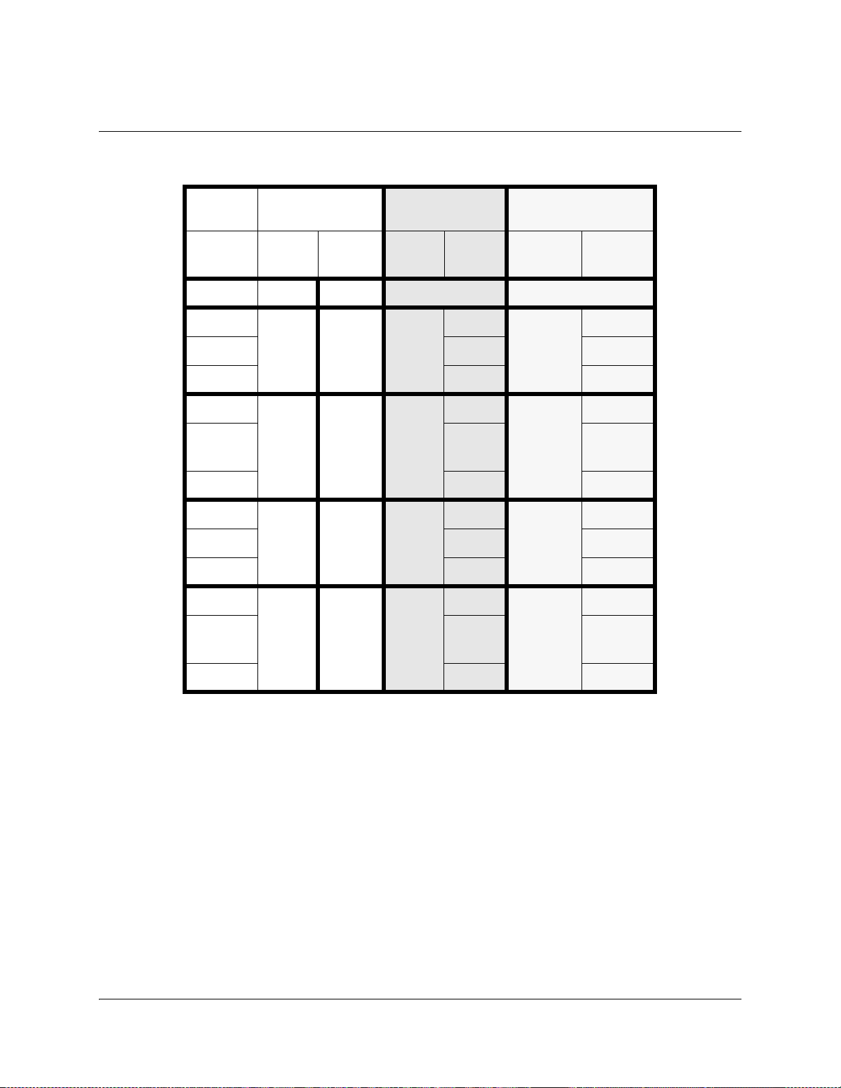
Connecting the Audio Inputs, Continued
The pinout for the digital part of the terminal block connector is as follows:
Channel
Numbering
Pin
Number
Layer IIDolby
Digital
1 to 12
13 5 & 6 3
14
15
16
17 Groun
AES/EBU AES-3id
Type Signal Type Signal
N/A N/A
Digital In+ Digital In Signal
- Ground
Shield Shield
Digital
Out
Signal Digital
Out
Signal
Ground
d
18
Shield Shield
19 7 & 8 4 Digital In+ Digital In Signal
20 - Ground
21 Shield Shield
22
23 Groun
Digital
Out
Signal Digital
Out
Signal
Ground
d
24
Shield Shield
Note: The digital audio output is always 75-ohm single-ended.
Note: The digital output on pin 16 corresponds settings-wise to the layer II
channels 5&6 and the Dolby Digital channel 3. Likewise the digital output on pin 22
corresponds settings-wise to the layer II channels 7&8 and the Dolby Digital
channel 4.
3-10 Installation 4020024 Rev C
Page 55

Connecting the Audio Inputs, Continued
To Connect the Audio Inputs
Do as follows to connect the audio inputs:
1. For digital channels 1 and 2 connect the audio input to the Digital Audio In
connector.
Hint: For digital audio connections, use a coaxial cable designed for 75-ohm
AES-3id.
2. For analog channels 1 and 2 do as follows:
Spring Cage Plug
Connector
3. For channels 3 and 4 connect the analog or digital audio input to the Ana/Dig
Audio In 3 & 4 part of the terminal block connector. The input type of channels 3
and 4 is set up in the GUI.
Hint: For digital audio connections, use a balanced cable designed for 110-ohm
AES/EBU digital audio or a coaxial cable designed for 75-ohm AES-3id. Use a
high-quality balanced audio cable for the analog inputs.
If you have many or heavy audio cables connected to the D9040 Encoder, you
may need to suspend the cables in your rack to prevent unnecessary mechanical
stress on the audio connector.
Step Action
1 Connect the analog audio input cable to the
spring cage plug connector.
Use a flat-blades screwdriver with a width of
2 mm and a maximum thickness of 0.4 mm to
press in the spring representing the pin to be
connected.
Push the wire in the hole above the spring
and release the spring.
2 Connect the spring cage plug connector to
the Analog Audio In 1 & 2 part of the
terminal block connector.
4. If relevant, use the Digital Out pins of channels 3 and/or 4 to synchronize
external equipment to a reference clock. The reference clock is locked to the
video.
4020024 Rev C Installation 3-11
Page 56

Connecting to the Contact Closure or Cue Tone Interfaces
Contact Closure and Cue Tone Connector
The D9040 Encoder has a contact closure and a cue tone interface (not used), which
can be used to trigger digital program insertion (DPI). The contact closure interface
has 8 inputs. The cue tone interface has two inputs.
Pin Allocation
The connector labeled CUE CON CLO is a 24-pin terminal block connector.
The following table shows the connector and the pin allocation.
Connector Drawing Pin
Number
1 Cue Tone In + 13 NC
2 Cue Tone In - 14 NC
3Ground15NC
4NC 16INC
5 Contact 1 17 Contact 5
6 Ground 18 Ground
7 Contact 2 19 Contact 6
8 Ground 20 Ground
9 Contact 3 21 Contact 7
10 Ground 22 Ground
11 Contact 4 23 Contact 8
12 Ground 24 Ground
Description Pin
Number
Description
Note: Contact open = not connected (internal pull-up).
Contact closed = connected to ground.
To Connect to the Contact Closure Interface
Connect the external contact closure equipment to the contact closure interface.
External contact closure equipment could be a Monroe DTMF decoder.
To Connect to the Cue Tone Interface (not used)
Connect the external cue tone equipment to the cue tone interface. External cue tone
®
equipment could be a PowerVu
3-12 Installation 4020024 Rev C
D9850 Program Receiver.
Page 57
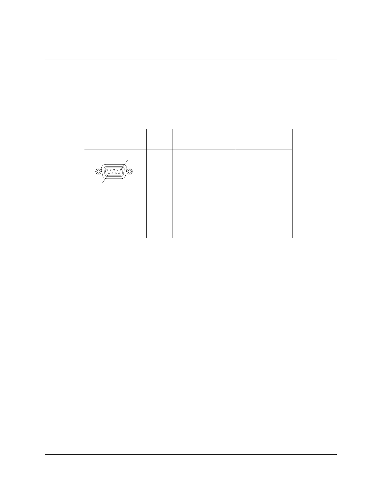
Connecting the Statmux Interface
Connector for the Statmux Input
The D9040 Encoder has one bidirectional RS-232 data channel for connection to the
Regulus Statistical Multiplex Controller.
The following table shows the female Statmux connector and the pin allocation for
the RS-232 input.
.
Connector Pin
1
9
To Connect the Statmux Interface
Do as follows to connect to the Statmux interface:
1. Connect the one-to-one RS-232 cable to the Statmux Interface connector.
Note: Use a shielded cable.
2. Connect the other end of the RS-232 cable to the Regulus Statistical Multiplex
Controller.
The D9040 Encoder automatically sets up the RS-232 communication
parameters when choosing statistical multiplexing.
number
1
2
3
4
5
6
7
8
9
RS-232 Connector
Pin allocation
Not connected
RxD (output)
TxD (input)
DTR (input)
GND
DSR (output)
RTS (input)
CTS (output)
Not connected
Signal
RS 232-E data
channel, at a bit
rate of
38,400 baud
Connector type:
9-pin sub-D
female
4020024 Rev C Installation 3-13
Page 58

Connecting an External Alarm System
Connector for an External Alarm System
The D9040 Encoder is equipped with a connector for alarm relay outputs for remote
alarm signaling.
The Alarm output connector is a 9-pin Sub-D female connector. The following
drawing shows the connector and the pin allocation table for the Alarm output
connector.
Connector Relay
9
1. Connect the cable from the external alarm system to the alarm connector.
Example, Alarm Relays
The following figure shows an example of how the alarm relays work.
For example, for an A-alarm under normal operational conditions (no alarm), pin 6
is closed, that is connected to pin 2 and pin 1 is open. However, should an alarm
condition occur pin 6 is open and pin 1 is closed, that is connected to pin 2. This
means that the A-alarm is active and the A-alarm LED lights on the front panel.
Function Normally
name
1
AA-Alarm 6 2 1
closed pin
Common
pin
Normally
open pin
BB-Alarm 7 8 3
CC-Alarm 4 5 9
6 Normally Closed (Inactive)
2 Common
1 Normally Open (Active)
02-085
Note: The A-alarm relay is always activated when the power is off or the D9040
Encoder is booting, whereas the other alarm relays maintain their status.
For example, if a B-alarm relay is inactive when the power is switched off, it stays
inactive. However, if it is active when the power is switched off, it stays active.
For information about the maximum relay load, see Alarm Interface, page A-18.
3-14 Installation 4020024 Rev C
Page 59

Connecting the Ethernet Management Interface
The Ethernet Interface
The RJ-45 interface for 10/100 BASE-T Ethernet is intended for PNC management.
Hint: If you experience problems with the 10 BASE-T Ethernet it is recommended
that you change it to a 100 BASE-T connection.
Note: You must set up the IP address, the default gateway and the subnet mask to
match the network connection. This is done through the front panel menu. For
further information, see Front Panel Setup, page 1-3.
Pin Allocation, Ethernet Connector
The table shows the Ethernet connector and the pin allocation (MDI interface):
Connector Pin Pin allocation
1Tx+
2Tx-
3Rx+
4Not connected
18
Informative Notes
Proper cables are required for reliable Ethernet operation; to run over a maximum
segment length of 100 m the cable has to comply with the EIA/TIA Category 5 wire
specifications.
To Connect the Ethernet Interface
1. Connect a crossed RJ-45 cable between the Ethernet connector on the D9040
Encoder and the Ethernet port of your PC.
Note: You need a crossover cable if you want to connect the Ethernet interface of
the D9040 Encoder directly to another Ethernet device without using a hub or
switch.
You need to set up the IP address on both the D9040 Encoder (via the front panel
display). For information on setting up the IP address via the front panel, see Front
Panel Setup, page 1-3.
00-052
5Not connected
6Rx-
7Not connected
8Not connected
4020024 Rev C Installation 3-15
Page 60

Connecting the ASI Outputs and the ASI Monitor Decoder
To Connect the ASI Outputs
Do as follows to connect to the ASI output:
1. Connect the output signals from the D9040 Encoder connectors ASI OUT 1 and/
or ASI OUT2 to the ASI input connectors of the equipment after the D9040
Encoder.
Use a 75-ohm double-braided cable.
The equipment after the D9040 Encoder could be a Transport Stream
Multiplexer such as the PowerVu Model D9140 Advanced Multilplexer.
Hint: The two outputs are identical and can be used for backup purposes.
2. If you want to check the ASI output signal connect an ASI monitor to the ASI
monitor connector.
Note: The ASI monitor output cannot be muted but otherwise it works just like
the two primary outputs.
3-16 Installation 4020024 Rev C
Page 61

Overview
Introduction
This chapter describes how to set up the D9040 Encoder using the front panel keys
and display.
In This Chapter
This chapter contains the following topics.
Chapter 4
Front Panel Operation
Topic See Page
About the Front Panel 4-2
Keypad Convention 4-4
Startup Screen 4-5
Main Menu 4-6
System Menu 4-7
4020024 Rev C Front Panel Operation 4-1
Page 62

About the Front Panel
Introduction
The D9040 Encoder is operated using controls and indicators on the front panel.
These include the numeric keypad, the Navigation/Selection keypad, the LCD, the
ALARM and POWER indicators. These are shown in the following
illustration:
Keypad
LCD
LCD Panel
The numeric keypad is used to enter alphanumeric values. The MENU key sets the
software to the initial menu and the PREV key or the UP arrow key returns to the
previous menu. The PREV key can also be used to cancel a numeric entry at any
point during the entry sequence, and the LEFT Arrow key allows backspacing
through the entry.
The LCD provides information on the selections available at any menu level,
current settings for parameters, and certain status and alarm indications. This is a
2x40, backlit LCD panel. The top line may be status data or identifier information. It
can also display optional functions available for tuning operations. The bottom line
will show selections or parameter values available using the navigation/selection
keypad. The items are selected by pressing the SELECT (center key) or DOWN
Arrow key on the navigation/selection keypad.
Alarm LED
Power LED
Navigation/
Selection Keypad
Numeric Keypad
Front Panel LEDs
For further information about the status signaling of the front panel LEDs, see Front
Panel LEDs, page 5-7.
4-2 Front Panel Operation 4020024 Rev C
Page 63

About the Front Panel, Continued
Navigation/Selection Keypad
The navigation keys (LEFT, RIGHT, UP and DOWN) and the SELECT key on this
keypad are the primary controllers. Each navigation key performs various
functions, depending on the current state of the menu system (i.e. sometimes the
left navigation key backspaces over an entry and sometimes moves the cursor to a
different menu item). Once the cursor is over the desired function, pressing the
SELECT (center key) or DOWN Arrow key selects the current item (this may go to
a different menu or change a setting). Pressing the SELECT key stores any entered
values.
4020024 Rev C Front Panel Operation 4-3
Page 64

Keypad Convention
Overview
Throughout this manual, there are references to parts of a keypad on
the front of the encoder. This is the Navigation/Selection keypad (see
diagram at right), which changes its function, depending on the
current state of the menu. For clarity, the following table shows which
parts of this integral interface are being referenced by which term.
When you see
It means…
this…
LEFT Arrow key Press the key on the left side of the
Navigation/Selection Keypad.
RIGHT Arrow key Press the key on the right side of the
Navigation/Selection Keypad.
UP Arrow key Press the key on the top of the
Navigation/Selection Keypad.
DOWN Arrow key Press the key on the bottom of the
Navigation/Selection Keypad.
SELECT key Press the key in the center of the
Navigation/Selection Keypad.
PREV key Press the key on the lower left of
the numeric keypad
1)
.
MENU key Press the key on the lower right of
a)
.
Alphanumeric
Entry
the numeric keypad
Pressing the numeric keys 0-9 once
will enter the respective digit into a
data entry field.
1. Numeric keypad keys are uniform. MENU and PREV have been enlarged here for effect.
4-4 Front Panel Operation 4020024 Rev C
Page 65

Startup Screen
Structure
On power up and initialization, an identifying startup screen displays the system
name and the IP address of the unit.
The startup screen contains the following parameters:
IP Address
System Name
Description: The system name as set in the PNC GUI. The system name is
IP Addr.
Description: The IP address of the D9040 Encoder. The IP address is set up from
D9040
centered on the top line of the Startup screen and is not displayed
on sub-pages. It is used for uniquely identifying the D9040 Encoder.
the System menu, see IP, Management, IP Address, page 4-7.
4020024 Rev C Front Panel Operation 4-5
Page 66

Main Menu
Structure
Operation of the Encoder Model D9040 begins at the Main menu. From the startup
screen press the MENU or SELECT key to view the Main menu.
Menu Selection
Select the desired function by moving the cursor left or right by pressing the LEFT
or RIGHT key. Once a selection is made by pressing the SELECT or the DOWN key,
the LCD presents the second menu level for the selected function. Succeeding levels
for each function are described in the following pages.
Main Menu
System Lock
4-6 Front Panel Operation 4020024 Rev C
Page 67

System Menu
Structure
To see the System menu from the Main menu, press the SELECT key.
Each parameter is described in the following. For instructions on how to select and
store settings, see About the Front Panel, page 4-2.
The menu has the following structure:
Status, Alarms
Parameters: N/A
Description: A list of active alarms in the system.
IP, Management, IP Address
Parameters: <0 to 255>.<0 to 255>.<0 to 255>.<0 to 255>
Description: The IP address of the management interface to the D9040 Encoder.
Contact your local network administrator to obtain an IP address.
Use the numeric keys to type the IP address.
Press the SELECT key to store the entered values.
Press the UP Arrow key to leave the menu.
When you leave the IP menu by pressing the UP Arrow once more
the IP, Mask and Gateway parameters are validated against each
other and stored. Any inconsistencies will be shown in the display.
Important: For the changes to take effect, you must reset the D9040 Encoder
IP, Management, Mask
Parameters: <0 to 255>.<0 to 255>.<0 to 255>.<0 to 255>
Description: The subnet mask of the management interface to the D9040
after you have finished setting or changing the IP address, subnet
mask and default gateway. The D9040 Encoder will display a
reminder.
Note: The reset may take up to 120 seconds.
Note: The IP Address is not affected by the Default command.
Encoder. Setup similar to IP, Management, IP Address, page 4-7,
above.
Note: The subnet mask is not affected by the Default command.
4020024 Rev C Front Panel Operation 4-7
Page 68

System Menu, Continued
IP, Management, Gateway
Parameters: <0 to 255>.<0 to 255>.<0 to 255>.<0 to 255>
Description: The default gateway of the management interface to D9040
Software Version
Parameters: N/A
Description: The software version of the system controller.
Module Info, Main
Parameters: N/A
Description: The hardware and the software part numbers of the main board.
Module Info, H.264
Parameters: N/A
Encoder. The D9040 Encoder uses this gateway to route IP traffic
across the network. Setup similar to IP, Management, IP Address,
page 4-7, above.
Note: The default gateway setting is not affected by the Default
command.
Hint: The default gateway 0.0.0.0 means that no gateway is used.
Description: The hardware and the software part numbers of the H.264 (VE6)
Module Info, Adv. Video Input
Parameters: N/A
Description: The hardware and the software part numbers of the Advanced
Module Info, Dual Audio
Parameters: N/A
Description: The hardware part number
board.
Video Input module.
1)
of the optional audio module. The
audio module contains two stereo channels or 4 mono channels.
1)The audio module has no software part number and will show N/A in the software part
number field.
4-8 Front Panel Operation 4020024 Rev C
Page 69

System Menu, Continued
Option License, PNC Management
Parameters: Enabled, Disabled
Description: The status of the license signifies the following:
Status Explanation
Enabled The option is present and enabled.
Disabled The option is either disabled or uninstalled. In
Note! This option is always pre-installed and enabled at delivery.
Option License, Statmux
Parameters: Enabled, Disabled
Description: The status of the license signifies the following:
Status Explanation
this case you have to enable or install the
option to make it work.
Note! This option is always pre-installed and enabled at delivery.
Option License, Closed Caption
Parameters: Enabled, Disabled
Description: The status of the license signifies the following:
Note! This option is always pre-installed and enabled at delivery.
Enabled The option is present and enabled.
Disabled The option is either disabled or uninstalled. In
this case you have to enable or install the
option to make it work.
Status Explanation
Enabled The option is present and enabled.
Disabled The option is either disabled or uninstalled. In
this case you have to enable or install the
option to make it work.
4020024 Rev C Front Panel Operation 4-9
Page 70

System Menu, Continued
Option License, Noise Reduction
Parameters: Enabled, Disabled
Description: The status of the license signifies the following:
Status Explanation
Enabled The option is present and enabled.
Disabled The option is either disabled or uninstalled. In
Note! This option is always pre-installed and enabled at delivery.
Option License, Pre-Analysis
Parameters: Enabled, Disabled
Description: The status of the license signifies the following:
Status Explanation
this case you have to enable or install the
option to make it work.
Enabled The option is present and enabled.
Disabled The option is either disabled or uninstalled. In
this case you have to enable or install the
option to make it work.
Note! This option is always pre-installed and enabled at delivery.
Option License, Dolby Digital, Channel 1, Channel 2, Channel 3 or Channel 4
Parameters: Enabled, Disabled
Description: You need an option license for each of the Dolby Digital channels.
The status of the license signifies the following:
Status Explanation
Enabled The option is present and enabled.
Disabled The option is either disabled or uninstalled. In this case
you have to enable or install the option to make it
work.
Please contact your local Cisco sales representative if
you want to buy an option.
4-10 Front Panel Operation 4020024 Rev C
Page 71

System Menu, Continued
Option License, DPI
Parameters: Enabled, Disabled
Description: The status of the license signifies the following:
Option License, VBI
Parameters: Enabled, Disabled
Note: VITC data in the incoming signal will automatically be transferred
Status Explanation
Enabled The option is present and enabled.
Disabled The option is either disabled or uninstalled. In
this case you have to enable or install the
option to make it work.
Please contact your local Cisco sales representative if
you want to buy an option.
to the transport stream output independently of the VBI option.
Description: The status of the license signifies the following:
Note! This option is always pre-installed and enabled at delivery.
Option License, Profile422
Parameters: Enabled, Disabled
Description: The status of the license signifies the following:
Status Explanation
Enabled The option is present and enabled.
Disabled The option is either disabled or uninstalled. In
this case you have to enable or install the
option to make it work.
Status Explanation
Enabled The option is present and enabled.
Disabled The option is either disabled or uninstalled. In
this case you have to enable or install the
option to make it work.
Please contact your local Cisco sales representative if
you want to buy an option.
4020024 Rev C Front Panel Operation 4-11
Page 72

System Menu, Continued
Option License, Auto Concatenation
Parameters: Enabled, Disabled
Description: The status of the license signifies the following:
Status Explanation
Enabled The option is present and enabled.
Disabled The option is either disabled or uninstalled. In this case
you have to enable or install the option to make it
work.
Please contact your local Cisco sales representative if
you want to buy an option.
Option License, AAC, Channel 1, Channel 3, Channel 5 or Channel 7
Parameters: Enabled, Disabled
Description: You need an option license for each of the AAC channels. The status
of the license signifies the following:
Reset
Status Explanation
Enabled The option is present and enabled.
Disabled The option is either disabled or uninstalled. In this case
you have to enable or install the option to make it
work.
Please contact your local Cisco sales representative if
you want to buy an option.
Parameters: N/A
Description: Resets (boots) the D9040 Encoder.
The D9040 Encoder displays a message asking you to confirm the
resetting of the unit. Press SELECT to reset the encoder, or press UP
or PREV to leave the menu without making any changes.
Hint: You should reset the D9040 Encoder if:
• there has been a temperature alarm causing the D9040 Encoder
to disable functionality.
• you have set or changed the IP address, subnet mask or gateway
of one of the IP interfaces of the D9040 Encoder via the front
panel display.
Note: The reset may take up to 120 seconds.
4-12 Front Panel Operation 4020024 Rev C
Page 73

System Menu, Continued
Default
Parameters: N/A
Description: The D9040 Encoder will display a message asking you to confirm
Reset Passwords
Parameters: N/A
Description: Use this feature if you want to reset the login for the telnet, FTP and
setting the unit to the default values. Press SELECT to set the unit to
the default values, or press UP or PREV to leave the menu without
making any changes.
Use the default settings if you have set up the D9040 Encoder with
illegal and incompatible settings to get the encoder back in a
functional state.
Note: The default may take up to 120 seconds.
web-based user interfaces. The D9040 Encoder will display a
message asking you to confirm resetting the passwords to their
default values.
Note: The Web GUI is used for diagnostics/troubleshooting
purposes only.
Press SELECT to reset the passwords, or press UP or PREV to leave
the menu without making any changes.
4020024 Rev C Front Panel Operation 4-13
Page 74

Lock Menu
Structure
Lock
To see the Lock menu from the Main menu press the RIGHT Arrow key five times
and the SELECT key.
Each parameter is described in the following. For instructions on how to select and
store settings, see About the Front Panel, page 4-2.
The menu has the following structure:
Lock
Unlocked
Locked
04-058
Parameters: Unlocked, Locked
Description: From this menu you may lock or unlock the front panel. When the
front panel is locked you can only see settings but not change them
from the front panel menus.
4-14 Front Panel Operation 4020024 Rev C
Page 75

Overview
Introduction
This chapter gives information to assist you in replacing the fan and fuses. It also
describes how the status of the D9040 Encoder is communicated via front panel
LEDs and messages.
In This Chapter
This chapter contains the following topics.
Chapter 5
Service and Maintenance
Topic See Page
Section A - Replacing Fans and Fuses 5-2
Introduction 5-2
Replacing the Fan 5-3
Replacing an AC Fuse in the Power Supply 5-6
Section B - Status Signaling 5-7
Front Panel LEDs 5-7
Messages 5-8
4020024 Rev C Service and Maintenance 5-1
Page 76

Section A - Replacing Fans and Fuses
Introduction
General Service Information
This section gives general service guidelines. Furthermore you find some
troubleshooting information.
Adjustment and Calibration
The D9040 Encoder does not require regular adjustments or calibrations, however
to ensure proper cooling it is recommended that the fan be replaced every four
years. In addition the fan can be replaced if the installed fan is not functioning
correctly.
5-2 Service and Maintenance 4020024 Rev C
Page 77

Replacing the Fan
General
To ensure proper cooling of the D9040 Encoder replace the fan every fourth year.
WARNING:
Allow only qualified service personnel to open the unit. Otherwise,
personal injury or equipment damage may occur.
Before You Start
You need the following tools and accessory:
Screwdriver, PH-1 N/A
Flat-bladed screwdriver N/A
Internal hex 5.5 mm screwdriver N/A
Fan kit 4008940
Item Part Number
To Replace the Fan
Do as follows to replace the fan:
1. Switch off the power to the D9040 Encoder, remove the power cord and
dismount the D9040 Encoder from the rack.
Pull on the connector to disconnect the cable. Never pull on the cable itself.
2. Unscrew the 8 screws holding the top plate.
Use a PH-1 screwdriver.
4020024 Rev C Service and Maintenance 5-3
Page 78

Replacing the Fan, Continued
3. Unscrew and remove the nuts and washers. Two in front of the fan unit,
and one at each side. Use an internal hex 5 mm screwdriver.
4. Unplug the fan connector at the main board.
5-4 Service and Maintenance 4020024 Rev C
Page 79

Replacing the Fan, Continued
5. Unplug the front panel connector from the main board.
6. Pull out the cable through the opening in the fan unit.
7. Replace the fan.
8. Mount in reverse order.
Important: Make sure that the cable with the front panel connector goes
through the opening in the fan unit and not below it.
9. Dispose of the old fan.
Do not dispose of the old fan through the household garbage collection system,
but follow your local regulations.
4020024 Rev C Service and Maintenance 5-5
Page 80

Replacing an AC Fuse in the Power Supply
To Replace an AC Fuse
To replace an AC fuse do the following:
1. Turn off the power to the D9040 Encoder.
2. Remove the power cord from the D9040 Encoder.
3. Open the lid holding the fuses.
Use a flat bladed screwdriver.
Note: There is a fuse in both phase conductors.
4. Pull out the lid.
98-017
5. Remove the blown fuse(s).
6. Insert a new fuse with the same rating.
The fuse rating for the D9040 Encoder is 2 AT.
CAUTION:
For continued protection against risk of fire replace only with same type and
rating of fuse.
7. Reinsert the lid.
5-6 Service and Maintenance 4020024 Rev C
Page 81

Front Panel LEDs
Overview
To help signal the status of operation or the presence of an alarm the D9040 Encoder
makes use of front panel LEDs.
The drawing below shows the LEDs on the front panel of the D9040 Encoder.
LED Function
The function of the LEDs is described in the table below.
Section B - Status Signaling
ALARM
SELECT
POWER
LED Signal Explanation Remedy
POWER Green The D9040 Encoder is
correctly powered
Off There is no power present. Check the AC line supply.
ALARM Red An A-alarm is active. See the explanation/remedy
Off No A-alarm is active. N/A
N/A
in Messages, page 5-8.
4020024 Rev C Service and Maintenance 5-7
Page 82

Messages
General
The status of the D9040 Encoder and its immediate surroundings is reported to the
PNC in the form of messages and alarms. In the PNC, you can enable or disable
messages and attach an alarm category to each message.
Before You Start
Messages from the D9040 Encoder are shown in the PNC alarm log. For information
on how to view the messages, see the PowerVu Network Centre 8.0 (or later) User’s
Guide.
D9040 Encoder Message List
The following shows an alphabetical list of examples of the the available messages,
their default status and an explanation of the messages that can be displayed on the
front panel LCD. For a complete of the available messages, see the PowerVu
Network Centre 8.0 (or later) User’s Guide. However, note that the messages may
appear slightly different in the PNC alarm log compared to the D9040 Encoder front
panel LCD.
Message Description and Remedy Severity Default
alarm
category
A general
hardware error
has occurred.
A general
software error has
occurred.
All settings were
defaulted.
An option has
expired.
Description: A general hardware error
has occurred. Remedy: When persistent,
contact your Cisco technical support
center for repair.
Description: A general software error has
occurred. Remedy: If problems are
observed, reset the encoder. When
persistent, contact your Cisco
technical support center for further
assistance.
Description: All settings were set to
default as a result of a default command.
Remedy: Not applicable.
Description: An installed option license
expired. Remedy: Order the needed
license through your local Cisco
technical support center.
Critical A On
Major B On
Information None On
Information None On
Enable
5-8 Service and Maintenance 4020024 Rev C
Page 83

Message Description and Remedy Severity Default
alarm
category
Enable
Application file
downloaded.
Description: An application code has
been downloaded to the encoder. The
system will reboot. Remedy: Wait for the
unit to reboot.
Backup required. Description: Backup is required. One of
the events configured to trigger a backup
event has occurred. Remedy: Look at the
other messages to find the cause of this
event.
Can’t enable
option as it is not
installed.
Description: The installed license file
doesn’t contain information about the
enabled license. Remedy: Order the
needed license through your local
Cisco technical support
center.
Clock
synchronization
failed.
Description: The device failed to fetch the
clock from the time server. Remedy:
Check the IP address for the clock server
and the IP routing. Also check that the
time server uses the RFC 867 (Day Time
Protocol).
Information None On
Critical None On
Information None On
Warning None On
Composite input
loss.
Composite
picture sync loss.
Dolby Digital:
AES/EBU audio
input error.
Dolby Digital:
Audio delay
error.
Description: There is no video source on
the composite video input. Remedy:
Examine the video input selection in the
GUI and check the video source.
Description: The composite video signal
does not comply with the specifications.
Remedy: Check the input signal
(frequency offset, jitter, etc.).
Description: The encoder failed to lock to
the audio frame or the audio sample
frequency is out of range. Remedy: Check
the cable and the incoming signal.
Description: It is not possible to
implement the requested audio delay.
Remedy: Decrease the audio data rate or
change video settings to decrease end-toend delay. Check relative and external
delay settings.
Major A On
Major B On
Major B On
Major B On
4020024 Rev C Service and Maintenance 5-9
Page 84

Message Description and Remedy Severity Default
alarm
category
Enable
Dolby Digital:
DSP Delay high
error.
Dolby Digital:
DSP Delay low
error.
Dolby Digital:
Embedded audio
not locked.
Dolby Digital:
Overload on the
audio input
signal.
Dolby Digital:
Passthrough
FRMSZCOD
lower and
changed.
Description: The audio delay setup on the
Audio DSP is too high. Remedy: Decrease
the audio delay.
Description: The audio delay setup on the
Audio DSP is too low. Remedy: Increase
the audio delay
Description: The encoder failed to lock to
the embedded audio. Remedy: Check that
the audio channels are embedded where
required. Check the sources of the
embedded audio.
Description: The audio input signal is
overloaded. The audio input level is too
high and close to the clipping level.
Remedy: Increase the clipping level or
reduce the input level.
Description: The frame size code field is
lower than expected and has changed.
Remedy: Lower the bit rate on the Dolby
Encoder.
Minor None On
Major B On
Major B On
Minor B On
Minor None On
Dolby Digital:
Passthrough
FRMSZCOD not
valid.
Dolby Digital:
Passthrough
FSCOD does not
match.
Dolby Digital:
Passthrough
FSCOD not valid.
Dolby Digital:
Passthrough no
sync.
Description: The frame size code field is
not valid. Remedy: Use a valid bit rate on
the Dolby Encoder.
Description: Sampling frequency code
field does not match. Remedy: Set the
sampling frequencies on the Dolby
Encoder and the passthrough encoder to
the same.
Description: The sampling frequency
code field is not valid. Remedy: Set the
sampling frequency on the Dolby
Encoder to a legal value.
Description: Passthrough input is
missing. Remedy: Apply Passthrough
signal.
Major B On
Major B On
Major B On
Major B On
5-10 Service and Maintenance 4020024 Rev C
Page 85

Message Description and Remedy Severity Default
alarm
category
Enable
Dolby Digital:
Passthrough rate
low.
Dolby Digital:
Passthrough rate
too high.
Dolby Digital:
PCR Rate error.
Dolby Digital: TS
rate/audio rate
mismatch.
DPI Cancel
triggered without
associated Start.
Description: The incoming bit rate on
passthrough is lower than the setting.
Remedy: Increase the selected bit rate.
Description: The incoming bit rate on
passthrough is too high. Remedy: No
action needed.
Description: The requested PCR rate can
non be achieved Remedy: No action
possible.
Description: The encoding rate is too high
compared to the TS rate, or the encoding
rate is too low. The encoding will restart.
Remedy: Check the settings. Change the
audio encoding rate or increase the TS
rate. If a FIFO error occurs recurrently,
contact your Cisco technical support
center.
Description: An external control signal
occurred out of sequence. A Start
command must be triggered before it can
be canceled. Remedy: Setup of
automation system may need to be
corrected.
Minor None On
Major B On
Minor None On
Major B On
Minor None On
DPI Message
trigger ignored
due to debounce
delay.
Description: The general purpose input
detected multiple triggers too close
together in time. Remedy: Reduce the
debounce delay setting, or increase the
Minor None On
time between triggers or provide
debounce protection to the general
purpose input.
DPI PTS delay
invalid.
Description: The relative delay setting has
made the splice_time() PTS value to
Major None On
reference a point in time that has already
occurred. Remedy: Change relative delay
parameters.
DPI Stop
triggered without
associated Start.
Description: An external control signal
occurred out of sequence. A Start
command must be triggered before it can
Minor None On
be stopped. Remedy: Setup of automation
system may need to be corrected.
4020024 Rev C Service and Maintenance 5-11
Page 86

Message Description and Remedy Severity Default
alarm
category
Enable
DPI Transport
packet overflow.
Description: Data were lost when
attempting to load a DPI message to the
buffer. Remedy: Increase the DPI bit rate.
EDH error: EDH
flag activated in
encoder.
Description: The EDH (Error Detected
Here) flag was activated in the encoder
for one of the three groups (ANC/AP/
FF). Remedy: Check your SDI source and
the equipment that generates EDH.
EDH input loss. Description: The EDH signal has
disappeared. The encoder receives no
EDH data. Remedy: Check your SDI
source and the equipment that generates
EDH.
Encoding
processing error.
Description: The internal MPEG
processing of the encoder failed. The
encoding will restart. Remedy: Check
your settings for parameter violations.
Observe the limitations in the manual. If
persistent, contact your Cisco
technical support center for further
assistance.
Major None On
Minor None Off
Major None Off
Major B On
Fan malfunction. Description: The system has detected a
fan malfunction. Remedy: Replace the fan
if it is not working correctly.
Front panel
unlocked.
Description: Settings in the device can
now be changed via the front panel.
Remedy: Not applicable.
Invalid system
type detected.
Description: The detected system type
does not comply with the system type
setting in the encoder. Remedy: Apply a
correct system type (525 or 625 lines) or
change the Video Input Type in the
encoder.
IP streaming
buffer full.
Description: Internal buffer for IP
streaming has been overwritten. TS
packets have been lost and picture quality
is degraded. Remedy: Lower the ASI
output bit rate or check that the video IP
network is not overloaded.
Critical A On
Warning None On
Major A On
Major B On
5-12 Service and Maintenance 4020024 Rev C
Page 87

Message Description and Remedy Severity Default
alarm
category
Enable
Layer II: AES/
EBU audio input
error.
Layer II: Audio
delay error.
Layer II: DSP
Delay high error
Layer II: DSP
Delay low error.
Layer II:
Embedded audio
not locked.
Description: The encoder failed to lock to
the audio frame or the audio sample
frequency is out of range. Remedy: Check
the cable and the incoming signal.
Description: It is not possible to
implement the requested audio delay.
Remedy: Decrease the audio data rate or
change video settings to decrease end-toend delay. Check relative and external
delay settings.
Description: The audio delay setup on the
Audio DSP is too high. Remedy: Decrease
the audio delay.
Description: The audio delay setup on the
Audio DSP is too low. Remedy: Increase
the audio delay.
Description: The encoder failed to lock to
the embedded audio. Remedy: Check that
the audio channels are embedded where
required. Check the sources of the
embedded audio.
Major B On
Major B On
Minor None On
Major B On
Major B On
Layer II:
Overload on the
audio input
signal.
Layer II: PCR rate
error.
Layer II: TS rate/
audio rate
mismatch.
Description: The audio input signal is
overloaded. The audio input level has
reached the clipping level. Remedy:
Increase the clipping level or reduce the
input level.
Description: The requested PCR rate
cannot be achieved. Remedy: No action
possible.
Description: The encoding rate is too high
compared to the TS rate or the encoding
rate is too low. The encoding will restart.
Remedy: Check the settings. Change the
audio encoding rate or increase the TS
rate. If a FIFO error occurs recurrently,
contact your Cisco technical support
center.
Minor B On
Minor None On
Major B On
4020024 Rev C Service and Maintenance 5-13
Page 88

Message Description and Remedy Severity Default
alarm
category
Enable
Power supply
failure.
Description: Power supply defective or
external power line broken Remedy:
Check power cable. If persistent, contact
your Cisco technical support center for
repair.
Power-up selftest failed.
Description: The internal power-up selftest failed. Remedy: When persistent,
contact your Cisco technical support
center for further assistance.
Regulus
connection error.
Description: Err
connection
to the Regulus Statistical
or detected on the RS-232
Multiplex Controller. Remedy: Check the
RS-232 connection between the Statistical
Multiplex Controller and the encoder.
Consult the manuals for information on
how to interconnect the devices.
SDI input loss. Description: There is no video source on
the SDI video input. Remedy: Examine
the video input selection in the GUI and
check the video source.
Major B On
Critical A On
Major B On
Major A On
SDI picture sync
loss.
Description: SDI picture sync loss. The
video signal does not comply with the
specifications. Remedy: Examine the
video signal. It may be off-frequency or
the signal is perhaps a composite signal.
Settings file is
rejected.
Description: No settings changed in the
device as the settings file contains
conflicting settings. Remedy: Not
applicable.
Settings updated. Description: The settings have changed
either by a settings file import or by a
change via the PNC. Remedy: Not
applicable.
Statmux interface
RS-232 error.
Description: An error in the RS-232
statmux interface has been detected.
Remedy: Check that the RS-232 cabling is
OK and that the equipment connected to
the RS-232 interface operates as required.
Major B On
Information None On
Information None On
Major B On
5-14 Service and Maintenance 4020024 Rev C
Page 89

Message Description and Remedy Severity Default
alarm
category
Enable
Subcarrier
unlock.
Description: The input is not able to lock
to the subcarrier. Remedy: The frequency
offset is likely too high. Color
reproduction may suffer. Check your
video source.
Sync unstable. Description: The composite video
synchronization signal is unstable.
Remedy: Check the video source or use a
frame synchronizer.
System boot
completed.
Teletext input
loss.
Description: System boot has been
completed. Remedy: Not applicable.
Description: The teletext signal has
disappeared from the input. Remedy:
Check your video source and the
equipment that generates teletext.
Temperature
approaching high
limit.
Description: The temperature is
approaching the upper limit for safe
operation. Remedy: Check that the Fan
malfunction message is enabled and not
active. Apply external cooling if the
ambient temperature is above 45 degrees
Celsius.
Major B On
Major B On
Information None On
Major None Off
Warning B On
Temperature
approaching low
limit.
Description: The temperature is
approaching the lower limit for safe
operation. Remedy: Raise the ambient
Warning B On
temperature to more than 0 (zero)
degrees Celsius.
Temperature
outside safe
limits.
Description: The temperature is outside
the safe limits. The unit will be shut
down. Remedy: Check that the Fan
Critical A On
malfunction message is enabled and not
active. Check that the ambient
temperature is within 0 - 45 degrees
Celsius.
The option
import string is
invalid.
Description: An option license file is
invalid. Remedy: Check the Host ID and
the ordered options in the option license
Information None On
file.
4020024 Rev C Service and Maintenance 5-15
Page 90

Message Description and Remedy Severity Default
alarm
category
Enable
TS rate/Video
rate mismatch.
Description: The encoding rate is too high
compared to the TS rate or the encoding
rate is too low. The encoding will restart.
Remedy: Check the settings. Change the
encoding rate or increase the TS rate. In a
statmux set-up, the TS rate of an encoder
must have room for the maximum
instantaneous encoding rate. If a FIFO
error occurs recurrently, contact your
Cisco technical support
center.
VII error. Description: The encoder has detected an
error in the VII signal. Remedy: Check
your SDI source and the equipment that
generates VII.
VITC input loss. Description: The VITC signal in the video
input signal has disappeared. Remedy:
Check your video source and the
equipment that generates VITC.
VPS input loss. Description: The VPS signal in the video
input signal has disappeared. Remedy:
Check your video source and the
equipment that generates VPS.
Major B On
Major None Off
Major None Off
Major None Off
WSS input loss. Description: The WSS signal in the video
Major None Off
input signal has disappeared. Remedy:
Check your video source and the
equipment that generates WSS.
5-16 Service and Maintenance 4020024 Rev C
Page 91

Chapter 6
Customer Information
If You Have Questions
If you have technical questions, call Cisco Services for assistance. Follow the
menu options to speak with a service engineer.
Access your company's extranet site to view or order additional technical
publications. For accessing instructions, contact the representative who handles
your account. Check your extranet site often as the information is updated
frequently
4020024 Rev C 6-1
Page 92

Page 93

Overview
Introduction
This appendix contains the technical specifications for the Encoder Model D9040.
Note: The technical specifications are subject to change without prior notice.
In This Appendix
This appendix contains the following topics.
Section A - Video Input and Processing A-2
MPEG-2 Encoder Specifications A-2
Composite Video Input A-3
VBI Specifications in Composite Video A-6
Appendix A
Technical Specifications
Topic See Page
SDI Input A-8
Embedded Data in SDI A-9
Section B - Audio Input and Processing A-12
Audio Input A-12
Audio Processing A-12
Section C - Data Interfaces A-16
Section D - Transport Stream Output A-17
Section E - Control and Management Interfaces A-18
Section F - Power and General Specifications A-20
4020024 Rev C Technical Specifications A-1
Page 94

Section A - Video Input and Processing
MPEG-2 Encoder Specifications
General
Item Specification
Number of channels 1
Encoding engine According to MPEG-2, MP@ML
Frame types I, P, and B frames
Encoding control Adaptive coding parameters and GOP
PreSightPlus pre-analysis Look-ahead for improved statistical
PreSightPlus noise reduction Advanced adaptive “Motion-
Systems 525/29.97 Hz and 625/25 Hz
Modes Fixed rate, statmux or capped VBR
controlled by pre-analysis
multiplexing and normal fixed rate
encoding.
compensated” temporal filter can be set to
Multiframe-3D, 2-Frame, or off, and
advanced adaptive spatial filter can be
switched on or off.
Video data bit rate MP@ML: 0.5 to 15 Mbit/s.
The minimum bit rate depends on picture
resolution and GOP (observe the
recommendations for minimum rate).
Video resolution 8 bits per sample
Chroma format 4:2:0, 4:2:2
Aspect Ratio 4:3, 16:9 for MPEG-2 or auto-detect on VII/
WSS
Line start, 625 lines encoding 23
Line start, 525 lines encoding
H Resolutions 352, 480, 528, 544, 640, 704 and 720
V Resolutions 576 (for 625/25) and 480 (for 525/29.97)
1. If possible, set the decoder to the corresponding line start.
22
1)
A-2 Technical Specifications 4020024 Rev C
Page 95

Composite Video Input
Video Formats
Composite video PAL systems B, D, G, H, I, K, M, N and
Input Characteristics
Number of inputs 1
Type of connector BNC female
Item Specification
NTSC system M, and J-NTSC acc. to BT
470-6
Item Specification
Nominal internal termination,
impedance
Return loss, internal or external
termination, with or without power
Nominal input level 0 dBV
Maximum non-useful DCcomponent
75 ohm
> 35 dB, 10 Hz to 5.5 MHz.
±4 V
Video Synchronization and Clamp, Onboard Composite Module
Item Specification
Non-math video sources No disturbances in picture with a
maximum subcarrier deviation of 1 Hz
Line frequency tolerance ±30 ppm of nominal line frequency, correct
sync and clamp.
Maximum input line time jitter 300 ns
Item Specification
Clamp low frequency suppression > 20 dB at 50 Hz
> 34 db at 5 Hz
Input level range -6 dBV to +3 dBV
Noise immunity S/N > 20 dB, unweighted
pp
Maximum input line time jitter ±100 ns
4020024 Rev C Technical Specifications A-3
pp
Page 96

Composite Video Input, Continued
Frame Synchronizer
Item Specification
Frame locking To an internal nominal 27 MHz reference or
Tolerance of the internal reference 10 ppm
an external reference via the analog REF IN
connector
Ref In
Audio wandering upon frame skip/
repeat (when frame synchronizer is
enabled)
VBI behavior upon frame skip/
repeat
Item Specification
Number of reference inputs One 75 ohm, internally terminated
Type of reference PAL/NTSC composite signal
Type of connector BNC
Return loss > 30 dB, 10 Hz to 5.5 MHz, with or without
Nominal input level 0 dBV
± 1 frame
Drop VBI data upon frame skip and don't
insert VBI in repeated frame upon frame
repeat
power
A-4 Technical Specifications 4020024 Rev C
Page 97

Composite Video Input, Continued
Composite Video Performance
Item Specification, Advanced
Video Input Module
Gain
Insertion gain ± 0.2 dB
Level stability ± 0.10 dB / 1 hour ± 0.15 dB/
24 hour
Noise
Quantization Noise, unified
weighted acc. to 567
Non-linear distortion
Differential Gain (encoder only) ≤ 1% peak to peak ≤ 4% peak to peak
Differential Phase (encoder
only)
Luminance Non Linearity ≤ 2% peak to peak ≤ 6 % peak to peak
Chrominance - luminance
intermodulation
Linear distortion
Short-time waveform distortion Κ
Line-time waveform distortion ≤ ± 0.5% ≤ ± 1%
Field-time waveform distortion ≤ ± 1% ≤ ± 3% in NTSC
Chrominance luminance inequality
Gain inequality ≤ ±2% ≤ ±4%
≤ -55 dB RMS weighted
relative to 0.7 V
≤ 1° peak to peak ≤ 4° peak to peak
≤ 1% ≤ 2 %
≤ 0.5% ≤ 2%
(p/b)
Specification, Onboard
Composite module
≤ -55 dB RMS weighted
relative to 0.7 V
≤ ± 2% in PAL
Delay inequality ±10 ns ± 26 ns
Steady state characteristics
Gain/Frequency characteristics
(codec)
Group delay response
(reference at 500 kHz)
Chrominance AM/PM Noise < -50 dB < -50 dB
4020024 Rev C Technical Specifications A-5
≤ ± 0.2 db; 10 Hz to 5.00 MHz
≥ -3 dB, 6 MHz
≤ -24 dB, 6.75 MHz
≤ -40 dB, 8 to 27 MHz
≤ ± 20 ns, 10 Hz to 5.5 MHz
≤ ± 0.65 db; 0.5 to 5.0 MHz
Page 98

VBI Specifications in Composite Video
VBI Processing
Item Specification
Teletext B
General Teletext B acc. to ITU-R BT.653-3
Lines in 625 lines systems 7 to 22, 320 to 335, maximum 16 lines per
Inverted Teletext Applicable for EBU and DVB teletext
Output formats According to EN 301 775 V1.1.1 (DVB-VBI
Nominal input data amplitude
0
1
Input data amplitude variation: +3 dB / -6 dB
Clock run-in 10 to 16 bits
Closed Captioning with V-chip
support
field for DVB
Teletext) and/or
according to EN 300472 V1.2.2, 1996. (EBU
teletext)
Black level (± 15 mV)
462 mV (± 40 mV)
General According to EIA-608
Lines in 525 lines systems 21 field 1 and 2 (284)
Output formats MPEG-2: EIA 608, SA Type 4, DVS 157
H.264, PIP/H.264: EIA 608 ATSC, EIA 608
SA Proprietary
VPS
General VPS acc. to IRT Richtlinie 8 R 6
Lines in 625 lines systems 16
Output format According to EN 301 775 V1.1.1
WSS
Type of signal According to ETS 300 294 (ETSI) or Vistek
Data Sheet 1649 (AFD)
Lines in 625 lines systems First half of line 23
Output format According to EN 301 775 V1.1.1
VITC
General According to ISO13818-2
Lines in 625 lines systems 6 to 22 and 319 to 335
Lines in 525 lines systems 10 to 20 and 273 to 282
A-6 Technical Specifications 4020024 Rev C
Page 99

VBI Specifications in Composite Video, Continued
DVB Compliant Transparent VBI
Item Specification
Lines in 625/50 7 to 23, 319 to 335
Lines in 525/60 10 to 22 field 1 and 10 to 22 field 2 (273 to
284)
Number of lines ≤ 2 VBI lines per field are transferred
transparently if no other DVB VBI is
present.
≤ 1 VBI line per field is transferred
transparently if any other DVB VBI is
present.
Signal type Sampled signal, 13.5 MHz
Synchronization pulse and burst are
regenerated in the output.
Transferred samples All luminance samples. Chrominance
samples are not transferred.
Quality The transparent lines must have a signal
quality identical to ordinary video
Dynamic range -50 to 750 mV relative to clamp
Output format According to EN 301 775 V1.1.1.
4020024 Rev C Technical Specifications A-7
Page 100

SDI Input
System
Video Formats
Signal form Y, CR, CB
Sampling structure 4:2:2
Line numbers/field rates 525/29.97 Hz, 625/25 Hz
Bit rate 270 Mbit/s ± 10 ppm
Video data word size 8 bit and 10 bit
Input Characteristics
Number of inputs 1
Connector BNC connector
Item Specification
Item Specification
Nominal input level 800 mV
nominal
pp
Bandwidth 10 Hz to 5.75 MHz ±0.2 dB (625/25)
Impedance 75 ohm unbalanced
Return loss ≥ 15 dB in the range 5 to 270 MHz
Minimum jitter acceptance 25% of clock period, as determined over a
period of one line
Interference rejection No bit errors in presence of superimposed
interfering signal
DC ± 2.5 V
< 1 kHz 2.5 V
1 kHz to 5 MHz 100 mV
> 5 MHz 40 mV
pp
pp
pp
pp
A-8 Technical Specifications 4020024 Rev C
 Loading...