

Page 1

Cisco CSR 1000V Series Cloud Services Router Software Configuration Guide
Cisco IOS XE Release 3.9S, 3.10S, 3.11S, 3.12S
First Published: July 26, 2012
Last Updated: June 27, 2014
Cisco Systems, Inc.
www.cisco.com
Cisco has more than 200 offices worldwide.
Addresses, phone numbers, and fax numbers
are listed on the Cisco website at
www.cisco.com/go/offices.
Text Part Number: OL-27477-07
Page 2

THE SPECIFICATIONS AND INFORMATION REGARDING THE PRODUCTS IN THIS MANUAL ARE SUBJECT TO CHANGE WITHOUT NOTICE. ALL
STATEMENTS, INFORMATION, AND RECOMMENDATIONS IN THIS MANUAL ARE BELIEVED TO BE ACCURATE BUT ARE PRESENTED WITHOUT
WARRANTY OF ANY KIND, EXPRESS OR IMPLIED. USERS MUST TAKE FULL RESPONSIBILITY FOR THEIR APPLICATION OF ANY PRODUCTS.
THE SOFTWARE LICENSE AND LIMITED WARRANTY FOR THE ACCOMPANYING PRODUCT ARE SET FORTH IN THE INFORMATION PACKET THAT
SHIPPED WITH THE PRODUCT AND ARE INCORPORATED HEREIN BY THIS REFERENCE. IF YOU ARE UNABLE TO LOCATE THE SOFTWARE LICENSE
OR LIMITED WARRANTY, CONTACT YOUR CISCO REPRESENTATIVE FOR A COPY.
The Cisco implementation of TCP header compression is an adaptation of a program developed by the University of California, Berkeley (UCB) as part of UCB’s public
domain version of the UNIX operating system. All rights reserved. Copyright © 1981, Regents of the University of California.
NOTWITHSTANDING ANY OTHER WARRANTY HEREIN, ALL DOCUMENT FILES AND SOFTWARE OF THESE SUPPLIERS ARE PROVIDED “AS IS” WITH
ALL FAULTS. CISCO AND THE ABOVE-NAMED SUPPLIERS DISCLAIM ALL WARRANTIES, EXPRESSED OR IMPLIED, INCLUDING, WITHOUT
LIMITATION, THOSE OF MERCHANTABILITY, FITNESS FOR A PARTICULAR PURPOSE AND NONINFRINGEMENT OR ARISING FROM A COURSE OF
DEALING, USAGE, OR TRADE PRACTICE.
IN NO EVENT SHALL CISCO OR ITS SUPPLIERS BE LIABLE FOR ANY INDIRECT, SPECIAL, CONSEQUENTIAL, OR INCIDENTAL DAMAGES, INCLUDING,
WITHOUT LIMITATION, LOST PROFITS OR LOSS OR DAMAGE TO DATA ARISING OUT OF THE USE OR INABILITY TO USE THIS MANUAL, EVEN IF CISCO
OR ITS SUPPLIERS HAVE BEEN ADVISED OF THE POSSIBILITY OF SUCH DAMAGES.
Cisco and the Cisco logo are trademarks or registered trademarks of Cisco and/or its affiliates in the U.S. and other countries. To view a list of Cisco trademarks, go to this
URL: www.cisco.com/go/trademarks. Third-party trademarks mentioned are the property of their respective owners. The use of the word partner does not imply a partnership
relationship between Cisco and any other company. (1110R)
Any Internet Protocol (IP) addresses and phone numbers used in this document are not intended to be actual addresses and phone numbers. Any examples, command display
output, network topology diagrams, and other figures included in the document are shown for illustrative purposes only. Any use of actual IP addresses or phone numbers in
illustrative content is unintentional and coincidental.
Cisco CSR 1000V Series Cloud Services Router Software Configuration Guide
Copyright © 2012–2014 Cisco Systems, Inc. All rights reserved.
Page 3

Preface
CONTENTS
CHAPTER
Objectives
v
Document Revision History vi
Organization vii
Related Documentation viii
Document Conventions viii
Obtaining Documentation and Submitting a Service Request ix
1 Cisco CSR 1000V Series
Cloud Services Router Overview
Introduction 1-1
Benefits of Virtualization Using the Cisco CSR 1000V Series Cloud Services Router 1-2
Software Configuration and Management Using the Cisco IOS XE CLI 1-2
Router Interfaces 1-3
Virtual Machine Requirements 1-4
Virtual Machines 1-4
Hypervisor Support 1-4
Hypervisor vNIC Requirements 1-5
Cisco CSR 1000V and Hypervisor Limitations 1-7
Server Requirements 1-8
1-1
OL-27477-07
Cisco CSR 1000V Series Software License Overview 1-8
Cisco CSR 1000V Series Architecture Differences from Hardware Platforms 1-12
Supported Cisco IOS XE Technologies 1-13
Management Support 1-20
Managing the Router Using Cisco Configuration Professional 1-20
Managing the Router Using the Cisco CSR 1000V REST API 1-20
Managing the Router Using Cisco Prime Network Services Controller 1-20
Related Cisco Product Compatibility 1-21
Cisco Unified Computing System (UCS) Products 1-21
Finding Support Information for Platforms and Cisco Software Images 1-22
Using Cisco Feature Navigator 1-22
Using the Software Advisor 1-22
Cisco CSR 1000V Series Cloud Services Router Software Configuration Guide
iii
Page 4

Contents
Using the Software Release Notes 1-22
CHAPTER
CHAPTER
2 Using Cisco IOS XE Software 2-1
Using Keyboard Shortcuts 2-1
Using the History Buffer to Recall Commands 2-1
Understanding the Command Modes 2-2
Getting Help 2-3
Finding Command Options 2-3
Using the no and default Forms of Commands 2-6
Saving Configuration Changes 2-6
Managing Configuration Files 2-7
NVRAM File Security 2-8
Filtering the Output of show and more Commands 2-8
Powering Off the Cisco CSR 1000V 2-8
3 Installation Overview 3-1
Introduction 3-1
Obtaining the Cisco CSR 1000V Software 3-3
Cisco CSR 1000V Installation Files 3-3
Cisco CSR 1000V Installation Options 3-3
Guidelines and Limitations 3-4
ROMMON and the Cisco CSR 1000V 3-5
CHAPTER
iv
Where to Go Next 3-5
4 Installing the Cisco CSR 1000V in VMware ESXi Environments 4-1
VMware ESXi Support Information 4-1
Supported VMware Features and Operations 4-4
Installation Requirements for VMware ESXi 4-9
Deploying the Cisco CSR 1000V OVA Template to the VM 4-10
Deploying the OVA Template to the VM 4-10
Deploying the Cisco CSR 1000V Software Using the Cisco Build, Deploy, Execute OVF Tool 4-14
Editing the Cisco CSR 1000V Basic Properties Using the vSphere GUI 4-17
Adding Custom Properties for the Cisco CSR 1000V 4-19
Manually Creating the VM and Installing the Cisco CSR 1000V Software Using the .iso File (VMware
ESXi)
4-21
Overview of Tasks for Manually Creating the Cisco CSR 1000V VM 4-21
Manually Creating the Cisco CSR 1000V VM Using the .iso File (VMware ESXi) 4-23
Increasing Performance on VMWare ESXi Configurations 4-25
Cisco CSR 1000V Series Cloud Services Router Software Configuration Guide
OL-27477-07
Page 5

Contents
CHAPTER
CHAPTER
5 Installing the Cisco CSR 1000V in
Citrix XenServer Environments
5-1
Citrix XenServer Support Information 5-1
Installation Requirements for Citrix XenServer 5-2
Manually Creating the Cisco CSR 1000V VM Using the .iso File (Citrix XenServer) 5-3
5-4
6 Installing the Cisco CSR 1000V in KVM Environments 6-1
Kernel Virtual Machine Support Information 6-1
KVM Support on OpenStack 6-1
Installation Requirements for KVM 6-2
Manually Creating the Cisco CSR 1000V VM Using the .iso File (KVM) 6-3
Creating the Cisco CSR 1000V KVM Instance on OpenStack Using the .qcow2 File 6-5
Creating the Instance Using the KVM Command 6-5
Creating the Instance Using the OpenStack Command Line Tool 6-6
Creating the Instance Using the OpenStack Dashboard 6-7
Increasing Performance on KVM Configurations 6-8
CHAPTER
CHAPTER
7 Installing the Cisco CSR 1000V in Microsoft Hyper-V Environments 7-1
Microsoft Hyper-V Support Information 7-1
Installation Requirements for Microsoft Hyper-V 7-2
Manually Creating the Cisco CSR 1000V VM Using the .iso File (Microsoft Hyper-V) 7-2
Prerequisites 7-3
Configuring the Server Manager Settings 7-3
Creating the VM 7-3
Configuring the VM Settings 7-4
Launching the VM to Boot the Cisco CSR 1000V 7-6
8 Booting the Cisco CSR 1000V and Accessing the Console 8-1
Booting the Cisco CSR 1000V as the VM 8-1
Accessing the Cisco CSR 1000V Console 8-3
Accessing the Cisco CSR 1000V Through the VM Console 8-3
Accessing the Cisco CSR 1000V Through the Virtual Serial Port 8-3
Creating Serial Console Access in VMware ESXi 8-4
Creating the Serial Console Access in KVM 8-5
Creating the Serial Console Access in Microsoft Hyper-V 8-5
Opening a Telnet Session to the Cisco CSR 1000V Console on the Virtual Serial Port 8-5
Changing the Console Port Access After Installation 8-6
OL-27477-07
Cisco CSR 1000V Series Cloud Services Router Software Configuration Guide
v
Page 6

Contents
CHAPTER
CHAPTER
CHAPTER
9 Upgrading the Cisco IOS XE Software 9-1
Prerequisites for the Software Upgrade Process 9-1
Saving Backup Copies of Your Old System Image and Configuration 9-2
Using TFTP or Remote Copy Protocol to Copy the System Image into Boot Flash Memory 9-4
Loading the New System Image 9-5
Loading the New System Image from the Cisco IOS XE Software 9-5
Loading the New System Image from GRUB Mode 9-8
Saving Backup Copies of Your New System Image and Configuration 9-9
Rebooting the Cisco CSR 1000V 9-11
10 Mapping Cisco CSR 1000V Network Interfaces to VM Network Interfaces 10-1
Mapping the Router Network Interfaces to Virtual Network Interface Cards 10-1
Adding and Deleting Network Interfaces on the Cisco CSR 1000V 10-3
Cisco CSR 1000V Network Interfaces and VM Cloning 10-4
Mapping Cisco CSR 1000V Network Interfaces with vSwitch Interfaces 10-5
11 Accessing and Using GRUB Mode 11-1
CHAPTER
About GRUB Mode and the Configuration Register 11-1
Accessing GRUB Mode 11-2
Using the GRUB Menu 11-3
Modifying the Configuration Register (confreg) 11-3
Changing the Configuration Register Settings 11-6
Displaying the Configuration Register Settings 11-6
12 Configuring Call Home for the Cisco CSR 1000V 12-1
Prerequisites for Call Home 12-1
Information About Call Home 12-2
Benefits of Using Call Home 12-2
Obtaining Smart Call Home Services 12-3
Anonymous Reporting 12-3
How to Configure Call Home 12-4
Configuring Smart Call Home (Single Command) 12-4
Configuring and Enabling Smart Call Home 12-6
Enabling and Disabling Call Home 12-6
Configuring Contact Information 12-7
Example 12-8
Configuring Destination Profiles 12-8
vi
Cisco CSR 1000V Series Cloud Services Router Software Configuration Guide
OL-27477-07
Page 7

Creating a New Destination Profile 12-9
Copying a Destination Profile 12-11
Setting Profiles to Anonymous Mode 12-12
Subscribing to Alert Groups 12-13
Periodic Notification 12-15
Message Severity Threshold 12-16
Configuring Snapshot Command List 12-17
Configuring General email Options 12-18
Example 12-20
Specifying Rate Limit for Sending Call Home Messages 12-20
Specifying HTTP Proxy Server 12-21
Enabling AAA Authorization to Run IOS Commands for Call Home Messages 12-22
Configuring Syslog Throttling 12-23
Configuring Call Home Data Privacy 12-24
Sending Call Home Communications Manually 12-25
Sending a Call Home Test Message Manually 12-25
Sending Call Home Alert Group Messages Manually 12-26
Submitting Call Home Analysis and Report Requests 12-27
Manually Sending Command Output Message for One Command or a Command List 12-28
Contents
Configuring Diagnostic Signatures 12-30
Prerequisites for Diagnostic Signatures 12-30
Information About Diagnostic Signatures 12-30
Diagnostic Signatures Overview 12-31
Diagnostic Signature Downloading 12-31
Diagnostic Signature Workflow 12-32
Diagnostic Signature Events and Actions 12-32
Diagnostic Signature Event Detection 12-32
Diagnostic Signature Actions 12-33
Diagnostic Signature Variables 12-33
How to Configure Diagnostic Signatures 12-34
Configuring the Call Home Service for Diagnostic Signatures 12-34
Configuring Diagnostic Signatures 12-36
Configuration Examples for Diagnostic Signatures 12-37
Displaying Call Home Configuration Information 12-38
Examples 12-39
Default Settings 12-44
Alert Group Trigger Events and Commands 12-44
OL-27477-07
Message Contents 12-45
Sample Syslog Alert Notification in XML Format 12-48
Cisco CSR 1000V Series Cloud Services Router Software Configuration Guide
vii
Page 8

Contents
CHAPTER
CHAPTER
13 Managing Cisco CSR 1000V Licenses 13-1
Activating Cisco CSR 1000V Licenses 13-1
Managing Technology Package and Throughput Licenses 13-1
License Upgrade and Downgrade Scenarios 13-2
Changing the Technology Package License Boot Level (Cisco IOS XE Release 3.10S and Later) 13-2
Managing the Throughput Level Licenses 13-3
Changing the Maximum Throughput Level 13-4
License-Based Restriction on Aggregate Bandwidth 13-6
Managing Memory Upgrade Licenses (Cisco IOS XE Release 3.11S and Later) 13-7
Requesting a New Virtual UDI 13-8
14 Configuring Support for Management Using the REST API 14-1
Introduction 14-1
Enabling REST API Support During Cisco CSR 1000V OVA Deployment 14-1
Enabling REST API Support Using the Cisco IOS XE CLI 14-3
Configuring the Management Interface to Support the REST API
(Cisco IOS XE Release 3.11S and Later)
14-3
Configuring HTTPS Support for the REST API Using the Cisco IOS XE CLI 14-6
Disabling REST API Support 14-7
Viewing the REST API Container Status 14-8
CHAPTER
CHAPTER
APPENDIX
I
NDEX
15 Configuring Support for Remote Management by the Cisco Prime Network Services
Controller
15-1
Configuring the Management Interface to Support Remote Management by the Cisco Prime Network
Services Controller
15-1
Configuring Remote Management by Cisco Prime Network Services Controller 15-4
Enabling Remote Management by the Cisco Prime Network Services Controller Host 15-4
Disabling Remote Management by the Cisco Prime Network Services Controller Host 15-6
16 Troubleshooting Cisco CSR 1000V VM Issues 16-1
Verifying the Cisco CSR 1000V Hardware and VM Requirements 16-1
Troubleshooting Network Connectivity Issues 16-2
Troubleshooting VM Performance Issues 16-2
A Rehosting the Cisco CSR 1000V License A-1
Voluntarily Rehosting the License to a New VM A-1
Obtaining a Rehost License if the System Fails A-4
viii
Cisco CSR 1000V Series Cloud Services Router Software Configuration Guide
OL-27477-07
Page 9

Objectives
Preface
This preface describes the objectives and organization of this document and explains how to find
additional information on related products and services. This preface contains the following sections:
• Objectives, page v
• Document Revision History, page vi
• Organization, page vii
• Related Documentation, page viii
• Document Conventions, page viii
• Obtaining Documentation and Submitting a Service Request, page ix
This document provides an overview of software functionality that is specific to the Cisco CSR 1000V
Series Cloud Services Router. It is not intended as a comprehensive guide to all of the software features
that can be run using the Cisco CSR 1000V Series router, but only the software aspects that are specific
to this router.
For information on general software features that are also available on the Cisco CSR 1000V Series
router, see the Cisco IOS XE technology guides for that specific software feature.
OL-27477-07
Cisco CSR 1000V Series Cloud Services Router Software Configuration Guide
v
Page 10

Document Revision History
The Document Revision History records technical changes to this document. The table shows the
Cisco IOS XE software release number, the date of the change, and a brief summary of the change
Release Date Change Summary
Cisco IOS XE
Release 3.9S
Cisco IOS XE
Release 3.10S
April 1, 2013
July 30, 2013
Preface
• Updates to Cisco IOS technology features
supported
• Support for throughput-based licenses
• Support for the Cisco Build, Deploy, Execute
OVF (BDEO) tool
• Support for the VMXNET3 vNIC interface
type
• Support for updating properties using the
vSphere GUI
• Support for VMware ESXi 5.1
• Support for the Citrix XenServer, version
6.0.2 hypervisor
• Support for the Kernel Virtual Machine
(KVM) hypervisor
Cisco IOS XE
Release 3.11S
Cisco IOS XE
Release 3.12S
November 21, 2013
March 28, 2014
• Support for technology-based licenses
• Support for 1vCPU and 4vCPU
configurations (VMware ESXi only)
• Initial support of REST API for selected
features
• Removal of the GigabitEthernet 0 interface
• Support added for 2 vCPU configurations
(VMware ESXi only)
• Support added for 1vCPU and 4vCPU
configurations (Citrix XenServer and KVM)
• Support for KVM using OpenStack
• Support for VXLAN termination
• Support for deploying the Cisco CSR 1000V
on Amazon Web Services
• Support for additional REST APIs
• Support for managing the router remotely
using Cisco Prime Network Services
Controller (PNSC)
• Support for the Microsoft Hyper-V
hypervisor
• Support for Cisco Call Home and Cisco Smart
Call Home
vi
• Support for additional REST APIs
Cisco CSR 1000V Series Cloud Services Router Software Configuration Guide
OL-27477-07
Page 11

Preface
Organization
Chapter Title Description
Chapter 1 “Cisco CSR 1000V Series Cloud
Chapter 2 “Using Cisco IOS XE Software” Provides an overview of Cisco IOS XE software.
Chapter 3 “Installation Overview” Provides information on the Cisco CSR 1000V
Chapter 4 “Installing the Cisco CSR 1000V in
Chapter 5 “Installing the Cisco CSR 1000V in
Chapter 6 “Installing the Cisco CSR 1000V in
Chapter 7 “Installing the Cisco CSR 1000V in
Chapter 8 “Booting the Cisco CSR 1000V and
Chapter 9 “Upgrading the Cisco IOS XE
Chapter 10 “Mapping Cisco CSR 1000V
Chapter 11 “Accessing and Using GRUB
Chapter 12 “Configuring Call Home for the
Chapter 13 “Managing Cisco CSR 1000V
Chapter 14 “Configuring Support for Manage-
Chapter 15 “Configuring Support for Remote
Chapter 16 “Troubleshooting Cisco CSR
Appendix A “Rehosting the Cisco CSR 1000V
Services Router Overview”
VMware ESXi Environments”
Citrix XenServer Environments”
KVM Environments”
Microsoft Hyper-V Environments”
Accessing the Console”
Software”
Network Interfaces to VM Network
Interfaces”
Mode”
Cisco CSR 1000V”
Licenses”
ment Using the REST API”
Management by the Cisco Prime
Network Services Controller”
1000V VM Issues”
License”
Provides an overview of the Cisco CSR 1000V
Series Cloud Services Router.
installation options.
Describes how to install the Cisco CSR 1000V on
a VMware ESXi VM.
Describes how to install the Cisco CSR 1000V on
a Citrix XenServer VM.
Describes how to install the Cisco CSR 1000V on
a Kernel Virtual Machine (KVM).
Describes how to install the Cisco CSR 1000V on
a Microsoft Hyper-V VM.
Describes how to boot the Cisco CSR 1000V and
access the console.
Describes how to upgrade the Cisco IOS XE
software on the Cisco CSR 1000V.
Provides information on how to map the
Cisco CSR 1000V router interfaces to the VM
network interfaces.
Describes how to access the GRUB interface and
how to change the configuration register settings.
Describes how to configure Call Home and Smart
Call Home.
Provides information on managing software
licenses for the Cisco CSR 1000V.
Provides information on how to configure the
Cisco CSR 1000V to enable management of the
router using the REST API.
Provides information on how to activate support for
Cisco Prime Network Services Controller (PNSC),
a GUI-based network management tool that can be
used to manage and provision the
Cisco CSR 1000V.
Provides information on how to troubleshoot issues
related to VM and router performance.
Provides information on rehosting the
Cisco CSR 1000V license to another VM.
OL-27477-07
Cisco CSR 1000V Series Cloud Services Router Software Configuration Guide
vii
Page 12

Related Documentation
This section refers you to other documentation that also might be useful as you configure your
Cisco CSR 1000V router. The documentation listed below is available online. The following documents
cover other important information for the Cisco CSR 1000V:
• Cisco CSR 1000V Series Cloud Services Router Release Notes
• Cisco CSR 1000V Series Cloud Services Router Deployment Guide for Amazon Web Services
• Cisco CSR 1000V Series Cloud Services Router REST API Management Reference Guide
The Cisco IOS XE release documentation home page contains technology guides and feature
documentation:
http://www.cisco.com/en/US/products/ps11174/tsd_products_support_series_home.html
For information on commands, see one of the following resources:
• Cisco IOS XE Software Command References
• Command Lookup Tool (cisco.com login required)
Preface
Document Conventions
This documentation uses the following conventions:
Convention Description
^ or Ctrl The ^ and Ctrl symbols represent the Control key. For example, the key combi-
string A string is a nonquoted set of characters shown in italics. For example, when
Command syntax descriptions use the following conventions:
Convention Description
bold Bold text indicates commands and keywords that you enter exactly as shown.
italics Italic text indicates arguments for which you supply values.
[x] Square brackets enclose an optional element (keyword or argument).
| A vertical line indicates a choice within an optional or required set of keywords
[x | y] Square brackets enclosing keywords or arguments separated by a vertical line
{x | y} Braces enclosing keywords or arguments separated by a vertical line indicate a
nation ^D or Ctrl-D means hold down the Control key while you press the D
key. Keys are indicated in capital letters but are not case sensitive.
setting an SNMP community string to public, do not use quotation marks around
the string or the string will include the quotation marks.
or arguments.
indicate an optional choice.
required choice.
viii
Cisco CSR 1000V Series Cloud Services Router Software Configuration Guide
OL-27477-07
Page 13

Preface
Nested sets of square brackets or braces indicate optional or required choices within optional or required
elements. For example:
Convention Description
[x {y | z}] Braces and a vertical line within square brackets indicate a required choice
within an optional element.
Examples use the following conventions:
Convention Description
screen
bold screen
Examples of information displayed on the screen are set in Courier font.
Examples of text that you must enter are set in Courier bold font.
< > Angle brackets enclose text that is not printed to the screen, such as passwords.
! An exclamation point at the beginning of a line indicates a comment line. (Ex-
clamation points are also displayed by the Cisco IOS XE software for certain
processes.)
[ ] Square brackets enclose default responses to system prompts.
The following conventions are used to attract the attention of the reader:
Note Means reader take note. Notes contain helpful suggestions or references to materials that may not be
contained in this manual.
Caution Means reader be careful. In this situation, you might do something that could result in equipment
damage or loss of data.
Obtaining Documentation and Submitting a Service Request
For information on obtaining documentation, submitting a service request, and gathering additional
information, see What’s New in Cisco Product Documentation at:
http://www.cisco.com/c/en/us/td/docs/general/whatsnew/whatsnew.html
Subscribe to What’s New in Cisco Product Documentation, which lists all new and revised Cisco technical
documentation, as an RSS feed and deliver content directly to your desktop using a reader application. The
RSS feeds are a free service.
OL-27477-07
Cisco CSR 1000V Series Cloud Services Router Software Configuration Guide
ix
Page 14

Preface
Cisco CSR 1000V Series Cloud Services Router Software Configuration Guide
x
OL-27477-07
Page 15

Introduction
CHA P T ER
Cisco CSR 1000V Series Cloud Services Router Overview
• Introduction
• Virtual Machine Requirements
• Cisco CSR 1000V Series Software License Overview
• Cisco CSR 1000V Series Architecture Differences from Hardware Platforms
• Supported Cisco IOS XE Technologies
• Management Support
• Finding Support Information for Platforms and Cisco Software Images
1
The Cisco CSR 1000V Series Cloud Services Router provides a cloud-based router that is deployed on
a virtual machine (VM) instance on x86 server hardware. The Cisco CSR 1000V provides selected
Cisco IOS XE features on a virtualization platform.
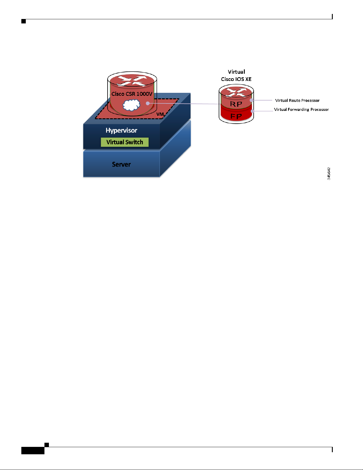
When the Cisco CSR 1000V virtual IOS XE software is deployed on a VM, the Cisco IOS XE software
functions just as if it were deployed on a traditional Cisco hardware platform. The Cisco CSR 1000V
includes a virtual Route Processor and a virtual Forwarding Processor (FP) as part of its architecture.
The Cisco CSR 1000V supports a subset of Cisco IOS XE software features and technologies. For more
information, see the “Supported Cisco IOS XE Technologies” section on page 1-13.
The Cisco CSR 1000V provides secure connectivity from the enterprise premise (such as a branch office
or data center) to the public or private cloud.
Figure 1-1 shows the basic virtual form factor for the Cisco CSR 1000V. The Cisco CSR 1000V is
deployed as a virtual machine on a hypervisor. Optionally, you can use a virtual switch (vSwitch),
depending on your deployment. You can use selected Cisco equipment for some components. The
supported components will depend on your software release.
OL-27477-07
Cisco CSR 1000V Series Cloud Services Router Software Configuration Guide
1-1
Page 16
Introduction
Chapter 1 Cisco CSR 1000V Series Cloud Services Router Overview
Figure 1-1 Cisco CSR 1000V Virtual Form Factor
Benefits of Virtualization Using the Cisco CSR 1000V Series Cloud Services Router
The Cisco CSR 1000V Series uses the benefits of virtualization in the cloud to provide the following:
• Hardware independence
Because the Cisco CSR 1000V runs on a virtual machine, it can be supported on any x86 hardware
that the virtualization platform supports.
• Sharing of resources
The resources used by the Cisco CSR 1000V are managed by the hypervisor, and resources can be
shared among VMs. The amount of hardware resources that the VM server allocates to a specific
VM can be reallocated to another VM on the server.
• Flexibility in deployment
You can easily move a VM from one server to another. Thus, you can move the Cisco CSR 1000V
from a server in one physical location to a server in another physical location without moving any
hardware resources.
Software Configuration and Management Using the Cisco IOS XE CLI
You can perform software configuration and management of the Cisco CSR 1000V using the following
methods:
• Provision a serial port in the VM and connect to access the Cisco IOS XE CLI commands.
• Use the VM console or the console on the virtual serial port to access the Cisco IOS XE CLI
commands.
1-2
Cisco CSR 1000V Series Cloud Services Router Software Configuration Guide
OL-27477-07
Page 17

Chapter 1 Cisco CSR 1000V Series Cloud Services Router Overview
Note A serial port can be used to manage a Cisco CSR 1000V VM only if the underlying hypervisor
supports associating a serial port with a VM. For example, the Citrix XenServer environment
does not support serial port association. See your hypervisor documentation for details.
• Use remote SSH/Telnet to access the Cisco IOS XE CLI commands.
The Cisco CSR 1000V also supports management and configuration using the following products:
• Cisco CSR 1000V REST API
• Cisco Prime Network Services Controller
For more information, see the “Management Support” section on page 1-20.
Router Interfaces
The Cisco CSR 1000V router interfaces perform the same functionality as those on hardware-based
Cisco routers. The Cisco CSR 1000V interfaces function as follows:
• Interfaces are logically named as the Gigabit Ethernet (GE) interfaces.
• The available interface numbering depends on the Cisco CSR 1000V version.
Virtual Machine Requirements
(Cisco IOS XE Release 3.11S and later) The interface numbering is as follows:
–
Interface port numbering is from 1 and up to the number of interfaces supported.
–
GigabitEthernet interface 0 is no longer supported beginning with this release.
–
You can designate any interface as the management interface. You can change the management
interface when deploying the OVA template on first-time installation.
(Cisco IOS XE Release 3.10S and earlier) The interface numbering is as follows:
–
Interface port numbering is from 0 and up to the number of interfaces supported.
–
Gigabit Ethernet interface 0 is reserved for the management interface used for obtaining the
licenses and upgrading software.
• At first boot, the Cisco CSR 1000V router interfaces are mapped to the vNIC interfaces on the VM
based on the vNIC enumeration to the Cisco CSR 1000V; on subsequent boot, the Cisco CSR 1000V
router interfaces are mapped to the vNIC MAC address
Caution If upgrading to Cisco IOS XE Release 3.11S from an earlier release, Cisco recommends you update your
configuration to remove the GigabitEthernet 0 management interface before upgrading. Because the
GigabitEthernet 0 interface is no longer supported beginning with Cisco IOS XE Release 3.11S, you will
receive system errors if the upgraded configuration includes this interface.
For more information, see the “Mapping Cisco CSR 1000V Network Interfaces to VM Network
Interfaces” section on page 10-1.
Virtual Machine Requirements
The Cisco CSR 1000V runs only on a virtual machine. This section describes the virtual machine
requirements for the router.
Cisco CSR 1000V Series Cloud Services Router Software Configuration Guide
OL-27477-07
1-3
Page 18

Virtual Machine Requirements
• Virtual Machines
• Hypervisor Support
• Server Requirements
Virtual Machines
A virtual machine (VM) is a software implementation of a computing environment in which an operating
system (OS) or program can be installed and run. The VM typically emulates a physical computing
environment, but requests for CPU, memory, hard disk, network and other hardware resources are
managed by a virtualization layer which translates these requests to the underlying physical hardware.
You can deploy an Open Virtualization Archive (OVA) file. The OVA file package simplifies the process
of deploying a VM by providing a complete definition of the parameters and resource allocation
requirements for the new VM.
An OVA file consists of a descriptor (.ovf) file, a storage (.vmdk) file and a manifest (.mf) file.
• ovf file—Descriptor file which is an xml file with extension .ovf which consists of all the metadata
• vmdk file—File format that encodes a single virtual disk from a VM.
• mf file—Optional file that stores the SHA key generated during packaging.
Chapter 1 Cisco CSR 1000V Series Cloud Services Router Overview
about the package. It encodes all the product details, virtual hardware requirements and licensing.
You can also install the Cisco CSR 1000V using an .iso file and manually create the VM in the
hypervisor.
For more information, see the “Cisco CSR 1000V Series Cloud Services Router Overview” section on
page 1-1.
Hypervisor Support
A hypervisor enables multiple operating systems to share a single hardware host machine. While each
operating system appears to have the dedicated use of the host's processor, memory, and other resources;
the hypervisor controls and allocates only needed resources to each operating system and ensures that
the operating systems (VMs) do not disrupt each other.
The Cisco CSR 1000V is supported for installation on selected hypervisors. The following table lists the
supported hypervisor versions for your software release.
Note Beginning with Cisco IOS XE Release 3.11S, the Cisco CSR 1000V can also be deployed on Cisco
Amazon Web Services. For more information, see the Cisco CSR 1000V Series Cloud Services Router
Deployment Guide for Amazon Web Services.
1-4
Cisco CSR 1000V Series Cloud Services Router Software Configuration Guide
OL-27477-07
Page 19

Chapter 1 Cisco CSR 1000V Series Cloud Services Router Overview
Table 1-1 Support Matrix for Hypervisor Versions
Virtual Machine Requirements
Cisco CSR 1000V
IOS XE Release
VMware
ESXi
Citrix
XenServer
Kernel Based Virtual
Machine (KVM) Microsoft Hyper-V
3.9S 5.0 Not supported Not supported Not supported
3.10S 5.0
5.1
6.0.2
• Linux KVM based on
Red Hat Enterprise
Linux 6.3
• Red Hat Enterprise
1
Not supported
Virtualization 3.1
3.11S 5.0
5.1
6.02
• Linux KVM based on
Red Hat Enterprise
Linux 6.3
• Red Hat Enterprise
1
Not supported
Virtualization 3.1
3.12S 5.0
5.1
5.5
6.1
• Ubuntu 12.04.03 LTS
Server 64 Bits
• Ubuntu 12.04.03 LTS
Server 64 Bits
• KVM installation on
2
Windows Server
2
2012 R2
OpenStack using
.qcow2 file
1. Requires Kernel version 2.6.3.2 and QEMU 0.12.
2. Requires QEMU-x86_64 version 1.0 (qemu-kvm-1.0), Copyright (c) 2003-2008 Fabrice Bellard.
Hypervisor features may differ depending on the hypervisor, and not all features in a given hypervisor
version may be supported. The hypervisor versions listed are those officially tested and supported by the
Cisco CSR 1000V. See the following sections for more information:
• VMware ESXi Support Information, page 4-1
• Citrix XenServer Support Information, page 5-1
• Kernel Virtual Machine Support Information, page 6-1
• Microsoft Hyper-V Support Information, page 7-1
Hypervisor vNIC Requirements
Depending on the Cisco CSR 1000V release version, each of the hypervisors supports different virtual
network interface card (vNIC) types. The Cisco CSR 1000V also supports a different maximum number
of vNICs depending on the hypervisor. Some versions and hypervisors also support the ability to add
and remove vNICs without powering down the VM. This feature is known as vNIC Hot Add/Remove.
The following table lists the supported vNICs and the minimum and maximum number of vNICs
supported for each VM instance.
OL-27477-07
Cisco CSR 1000V Series Cloud Services Router Software Configuration Guide
1-5
Page 20

Virtual Machine Requirements
Table 1-2 Cisco CSR 1000V vNIC Support
Cisco IOS XE Release: 3.9S 3.10S, 3.11S 3.12S
VMware ESXi:
NIC Types Supported VMXNET3 VMXNET3 VMXNET3
Max. number of vNICs
per VM instance
vNIC Hot Add/Remove
Support
Single Root I/O
virtualization (SR-IOV)
Support
Citrix XenServer:
NIC Types Supported — VIF VIF
Max. number of vNICs
per VM instance
vNIC Hot Add/Remove
Support
Single Root I/O
virtualization (SR-IOV)
Support
KVM:
NIC Types Supported — Virtio Virtio
Max. number of vNICs
per VM instance
vNIC Hot Add/Remove
Support
Single Root I/O
virtualization (SR-IOV)
Support
Microsoft Hyper-V:
NIC Types Supported — — HV NETVSC
Max. number of vNICs
per VM instance
vNIC Hot Add/Remove
Support
Single Root I/O
virtualization (SR-IOV)
Support
1. Requires the host hardware to support the Intel VT-d or AMD IOMMU specification.
SR-IOV is not supported with Virtual LANs (VLANs).
2. Supported beginning with the Cisco IOS XE 3.12.1 release.
3. Requires the Cisco CSR 1000V to be reloaded.
Chapter 1 Cisco CSR 1000V Series Cloud Services Router Overview
10 10 10
No Yes Yes
—— No
—7 7
—No No
Yes
2
3
2
—— Yes
1
—10 26
—Yes
3
—— Yes
1
—— 3
—— No
—— No
1-6
Cisco CSR 1000V Series Cloud Services Router Software Configuration Guide
OL-27477-07
Page 21

Chapter 1 Cisco CSR 1000V Series Cloud Services Router Overview
The VMXNET3, VIF and Virtio NIC types are para-virtualized NICs.
Note vNIC Hot Remove requires reloading the Cisco CSR 1000V.
Cisco CSR 1000V and Hypervisor Limitations
This section describes performance limitations due to how the Cisco CSR 1000V integrates with the
supported hypervisors.
Cisco CSR 1000V and Hypervisor Limitations for Cisco IOS XE Release 3.12S
• When the Cisco CSR 1000V is installed on Microsoft Hyper-V, the interface numbers can change
after Microsoft Hyper-V fails over to a new server, or restarts after a live migration.
–
If the server is set to perform ungraceful failover, there is no workaround.
–
If the server is set to perform graceful failover or restart, enter the clear platform software
vnic-if nvtable command before executing the failover or restart.
This issue is not seen if the maximum number of interfaces is configured.
• When the Cisco CSR 1000V is installed on Microsoft Hyper-V, if you want to configure a VLAN,
you must configure the VLAN interfaces on Microsoft Hyper-V using the Hyper-V Power Shell CLI.
Virtual Machine Requirements
• When the Cisco CSR 1000V is installed on Microsoft Hyper-V and an NSF-based virtual hard disk
is used, if there is a network connectivity issue between the Cisco CSR 1000V and the NSF server,
the Cisco CSR 1000V is unable to use the virtual hard disk even if the network connection is
restored. You must reboot the Cisco CSR 1000V to restore access to the virtual hard disk.
Cisco CSR 1000V and Hypervisor Limitations for Cisco IOS XE Release 3.10S
• Configuring Network Based Application Recognition (NBAR), or Application Visibility and
Control (AVC) support on the Cisco CSR 1000V requires a minimum of 4GB of DRAM on the VM,
even when using the one vCPU configuration on the VM.
• On the Cisco CSR 1000V, all the NICs are logically named as the Gigabit Ethernet interface. The
Cisco CSR 1000V does support the 10G IXGBE vNIC in passthrough mode; but that interface also
is also logically named as a Gigabit Ethernet interface. Note that with emulated devices like
VMXNET3/PV/VIRTIO from the hypervisor, the Cisco CSR 1000V is not aware of the underlying
interfaces. The vSwitch may be connected to a 10-GB physical NIC or 1-GB physical NICs or
multiple NICs (with NIC teaming on the hypervisor) as well.
• The Cisco CSR 1000V supports an MTU range from 1500 to 9216 bytes. However, the maximum
MTU supported on your hypervisor version may be lower. The MTU value configured on the
Cisco CSR 1000V should not exceed the maximum MTU value supported on the hypervisor.
Cisco CSR 1000V and Hypervisor Limitations for Cisco IOS XE Release 3.9S
The following are the Cisco CSR 1000V and VMware ESXi limitations for Cisco IOS XE Release 3.9S:
• The Cisco CSR 1000V interface bandwidth defaults to 1 GB, irrespective of the hypervisor’s
physical NIC bandwidth. The routing protocols (OSPF, EIGRP) use the Cisco CSR 1000V interface
bandwidth values for calculating the costs, not the physical NIC bandwidth.
OL-27477-07
Cisco CSR 1000V Series Cloud Services Router Software Configuration Guide
1-7
Page 22

Cisco CSR 1000V Series Software License Overview
• When a Cisco CSR 1000V interface is directly connected to a physical router, and that physical
router’s connecting interface goes down, the change is not reflected on the Cisco CSR 1000V. This
is because the Cisco CSR 1000V is actually connected to the hypervisor’s vSwitch and the vSwitch
uplink port is connected to the physical interface of the router. This behavior is expected.
• The Cisco CSR 1000V provides an MTU range from 1500 to 9216 bytes. However, ESXi 5.0
supports only a maximum value of 9000 bytes.
Server Requirements
The server and processor requirements are different depending on the Cisco CSR 1000V release.
Table 1-3 Server Requirements
Cisco CSR 1000V Release Intel AMD
Cisco IOS XE Release
3.9S
Cisco IOS XE Releases
3.10S, 3.11S, 3.12S
Chapter 1 Cisco CSR 1000V Series Cloud Services Router Overview
Intel Nehalem and
later-generation
processors are
supported.
Intel processors prior
to the Nehalem
generation are
supported.
Not supported
Supported
For more information, see the Cisco CSR 1000V Series Cloud Services Router Release Notes.
Note In Cisco IOS XE Release 3.9S and earlier, the Cisco CSR 1000V uses instructions not supported on Intel
pre-Nehalem generation processors. The existence of the required Nehalem or later processor instruction
set is determined at boot time. If the required instructions are not present, the following message is
displayed:
%IOSXEBOOT-4-BOOT_HALT: (rp/0): Halted boot due to missing CPU feature
requirement(s)
For more information, see the “Installation Overview” section on page 3-1.
Cisco CSR 1000V Series Software License Overview
The Cisco CSR 1000V Series software supports the standard Cisco software licensing process in
Cisco IOS XE. The software activation process is similar to other Cisco router products, but there are
some differences and additional requirements.
The Cisco CSR 1000V supports the following license types depending on the software release:
• Perpetual and subscription term licenses for 1, 3, and 5 years based on the following attributes:
–
Cisco IOS XE technology packages (Standard, Advanced and Premium)
–
Maximum supported throughput level (10, 25, 50, 100, 250, or 500 Mbps, and 1, 2.5 or 5 Gbps )
1-8
Cisco CSR 1000V Series Cloud Services Router Software Configuration Guide
OL-27477-07
Page 23

Chapter 1 Cisco CSR 1000V Series Cloud Services Router Overview
• Memory upgrade licenses (selected technology packages and throughput levels only)
• 60-day evaluation licenses
The following table lists the available license types for your release. See the Cisco CSR 1000V Series
Cloud Services Router Release Notes for the specific license SKUs and the Cisco CSR 1000V Router
Data Sheet.
Table 1-4 Cisco CSR 1000V Software License Types
Cisco CSR 1000V Version License Type License Term
All Evaluation 60 days
Cisco IOS XE Release 3.9S Base subscription technology package
licenses (Standard, Advanced, and Premium)
for the following throughput maximums:
• 10 Mbps
• 25 Mbps
• 50 Mbps
Cisco IOS XE Releases
3.10S, 3.11S
Base subscription Standard technology
package licenses for the following throughput
maximums:
• 10 Mbps
• 50 Mbps
Cisco CSR 1000V Series Software License Overview
1, 3, and 5 years
• 1 and 3 years
• Perpetual
• 100 Mbps
• 250 Mbps
• 500 Mbps
• 1 Gbps
Base subscription Advanced and Premium
technology package licenses for the following
throughput maximums:
• 10 Mbps
• 50 Mbps
• 100 Mbps
• 250 Mbps
• (Cisco IOS XE Release 3.11S and later)
License to add 8 GB of memory with
route reflector support
Note Selected licenses are available
1
through a Cisco service representative
only.
OL-27477-07
Cisco CSR 1000V Series Cloud Services Router Software Configuration Guide
1-9
Page 24

Cisco CSR 1000V Series Software License Overview
Table 1-4 Cisco CSR 1000V Software License Types (continued)
Cisco CSR 1000V Version License Type License Term
Cisco IOS XE Release
3.12S
Cisco IOS XE Release
3.12.1S
Chapter 1 Cisco CSR 1000V Series Cloud Services Router Overview
All of the licenses supported in Cisco IOS XE
Release 3.11S, plus the following licenses:
Base subscription Advanced and Premium
technology package licenses for the following
throughput maximum:
• 1 Gbps
Base subscription Standard, Advanced and
Premium technology package licenses for the
following throughput maximum:
• 2.5 Gbps
Base subscription Standard technology
package licenses for the following throughput
maximum:
• 5 Gbps
New technology package licenses are
supported:
• IPBase package license, with the same
feature set as the Standard package
• Security package license, with the same
feature set as the Advanced package
• AX package license, with the same
feature set as the Premium package
• 1 and 3 years
• Perpetual
• 1 and 3 years
• Perpetual
Cisco recommends using these technology
packages for compatibility with future
releases. All technology packages support the
same throughput maximums as feature sets in
earlier releases.
1. Available for the Premium package only. The additional memory is allocated to IOSD processes on the router only. The
memory upgrade license does not add available memory on the VM.
The supported performance indicates the maximum throughput supported by the Cisco CSR 1000V for
the license. If the throughput exceeds the supported performance, the router may experience dropped
packets and you will receive notification that the supported performance has been exceeded. The
Cisco CSR 1000V uses a performance limiter to regulate the throughput level. For more information, see
the “License-Based Restriction on Aggregate Bandwidth” section on page 13-6.
If additional performance is required, an additional license for a separate Cisco CSR 1000V VM must
be purchased. The Cisco CSR 1000V supports only one router instance per VM.
The Cisco CSR 1000V software licenses operate as follows:
• Each software license can be used for only one VM.
• You can install more than one license on a VM, but the multiple licenses can only apply to that VM.
1-10
Cisco CSR 1000V Series Cloud Services Router Software Configuration Guide
OL-27477-07
Page 25

Chapter 1 Cisco CSR 1000V Series Cloud Services Router Overview
• Similar to other Cisco hardware products, the software license is node-locked to the unique device
identifier (UDI) of that product. The Cisco CSR 1000V generates a Virtual UDI (vUDI) when first
installed on the VM, and licenses are node-locked to that vUDI. One license per VM instance is
required. Instances that are cloned from a repository must generate a new vUDI.
Note When you clone the Cisco CSR 1000V, you will automatically get a new vUDI, and all the
licenses from the original VM should be removed.
• You must purchase and install a new technology level license if you want to upgrade or downgrade
the technology level. For example, if you have a Premium technology package license and you want
to downgrade to the Standard technology package, you must purchase a new Standard technology
package license.
• In Cisco IOS XE Release 3.10S, the default license will not enable advanced IPsec features and
MPLS.
• The Cisco CSR 1000V does not provide or support Right-to-Use performance licenses.
• You will receive warning notices that the subscription term license will expire beginning eight
weeks before license expiration.
The licenses must be activated in order for the Cisco CSR 1000V network ports to provide the supported
throughput.
When the Cisco CSR 1000V is first booted, the router operates in evaluation mode, and provides limited
feature support and is limited to a maximum throughput of 2.5 Mbps. To obtain the full feature support
and throughput provided by your license, you must do the following:
Cisco CSR 1000V Series Software License Overview
• To access the features supported in your license, you must enter the license boot-level command
and set it to the level supported by your license (Standard, Advanced, or Premium).
• To set the throughput level to match your license, you must enter the platform
hardware-throughput command.
• You must then reboot the Cisco CSR 1000V for these settings to take effect.
If the throughput license expires or becomes invalid, the maximum throughput of the router reverts to
2.5 Mbps. When the 60-day evaluation license expires, the maximum throughput reverts to 2.5 Mbps and
to the limited feature set.
The subscription term begins on the day the license is issued.
For more information about license activation, see the “Managing Cisco CSR 1000V Licenses” section
on page 13-1.
If you rehost the Cisco CSR 1000V to a VM on another server, the following rules apply:
• You must purchase a new rehost software license that lasts for the period remaining on the original
license.
• If the original license was renewed, the rehosted software license will last for the period remaining
on the renewed license.
• You have a 60-day grace period to remove the software license from the original server hardware
and activate it on the rehosted server hardware.
The Cisco CSR 1000V also supports Cisco License Manager and Cisco License Call Home. For more
information about the standard Cisco IOS XE software activation procedure, and information about
Cisco License Manager and Cisco License Call Home, see the Software Activation Configuration Guide,
Cisco IOS XE Release 3S.
OL-27477-07
Cisco CSR 1000V Series Cloud Services Router Software Configuration Guide
1-11
Page 26

Chapter 1 Cisco CSR 1000V Series Cloud Services Router Overview
Cisco CSR 1000V Series Architecture Differences from Hardware Platforms
Cisco CSR 1000V Series Architecture Differences from
Hardware Platforms
Unlike traditional Cisco hardware router platforms, the Cisco CSR 1000V Series is a virtual router that
runs independently on an x86 machine. As a result, the Cisco CSR 1000V Series architecture has unique
attributes that differentiate it from hardware-based router platforms.
For example, Table 1-5 lists a comparison of some key areas where the Cisco CSR 1000V Series differs
from the Cisco ASR 1000 series routers.
Table 1-5 Cisco CSR 1000V Series Architecture Differences with Cisco ASR 1000 Series Routers
Feature Cisco ASR 1000 Series Cisco CSR 1000V Series
Hard Disk Supported. The Cisco CSR 1000V does not include
a hard disk. The software image is
stored on bootflash only (8 GB).
Physical resources Managed by architecture of the
hardware platform.
Console types supported Physical serial port.
Managed by the hypervisor. Physical
resources are shared among VMs.
• VMware soft console
• Network option (virtual terminal
server)
• Named pipe option
• Physical serial port on the ESXi or
KVM host
ROMMON Supported. The Cisco CSR 1000V does not include
ROMMON, but uses GRUB to provide
similar but more limited functionality.
Break Signal Supported. Not supported.
Port numbering See the Cisco ASR1000
documentation.
ISSU Supports In-Service Software
Upgrades (ISSU).
Subpackage upgrades Supports installation of
subpackages for specific SPAs
and SIP SPAs.
Diagnostic mode Supported. Not supported.
Dynamic addition/deletion
of ports
1. Requires reload of the VM.
Supported. Supported.
Gigabit Ethernet x ports only.
Not supported.
Subpackages not supported. The
Cisco CSR 1000V does not support
SPAs.
1
1-12
Cisco CSR 1000V Series Cloud Services Router Software Configuration Guide
OL-27477-07
Page 27

Chapter 1 Cisco CSR 1000V Series Cloud Services Router Overview
Supported Cisco IOS XE Technologies
The Cisco CSR 1000V Series Cloud Services Router supports selected Cisco IOS XE technologies. The
Cisco CSR 1000V supports a more limited set of functionality compared to other router platforms.
Table 1- 6 lists the major Cisco IOS XE technologies the Cisco CSR 1000V supports. Technologies not
listed are not currently supported on the Cisco CSR 1000V. Not all features in a given technology may
be supported. To verify support for specific features, use Cisco Feature Navigator. For more information,
see the “Using Cisco Feature Navigator” section on page 1-22.
In Cisco IOS XE Release 3.9S, the Cisco CSR 1000V supports a maximum of 150 IPsec tunnels.
Beginning with Cisco IOS XE Release 3.10S, the number of IPSec tunnels depends on the installed
license. For more information, see the Cisco CSR 1000V Series Cloud Services Router Release Notes.
The information listed in this table applies only if using the Cisco IOS XE CLI. Support for Cisco IOS
XE technologies is more limited in the following scenarios:
• When deploying the Cisco CSR 1000V on Amazon Web Services (AWS)
For more information, see the Cisco CSR 1000V Series Cloud Services Router Deployment Guide
for Amazon Web Services.
• When using the REST API to manage the Cisco CSR 1000V
For more information, see the “Configuring Support for Management Using the REST API” section
on page 14-1. For information about Cisco IOS XE technologies supported by the REST API, see
the Cisco CSR 1000V Series Cloud Services Router REST API Management Reference Guide.
• When using Cisco Prime Network Services Controller (PNSC) to remotely manage the
Cisco CSR 1000V
Supported Cisco IOS XE Technologies
For more information on features supported, see the “Configuring Support for Remote Management
by the Cisco Prime Network Services Controller” section on page 15-1.
Note The license technology packages available beginning with Cisco IOS XE release 3.12.1 support the same
sets of features as technology packages supported in previous releases. For example, the IPBase package
supports Standard package features, the Security package supports Advanced package features, and the
AX package supports the Premium package set of features.
Table 1-6 Cisco IOS XE Technologies Supported on the Cisco CSR 1000V Cloud Services Router
Minimum Cisco IOS
XE Release
Technologies
Supported
Required for
Cisco CSR 1000V
Technology Package
Licenses Supported
See the Following
Documentation:
IP:
• IPv4 Routing
• IPv4
Fragmentation
and Reassembly
• IPv6 Forwarding
Cisco IOS XE
Release 3.9S
• Standard
• Advanced
• Premium
• IP Addressing
Configuration Guide
Library, Cisco IOS XE
Release 3S
• Cisco IOS IP Addressing
Services Command
Reference
OL-27477-07
Cisco CSR 1000V Series Cloud Services Router Software Configuration Guide
1-13
Page 28

Supported Cisco IOS XE Technologies
Table 1-6 Cisco IOS XE Technologies Supported on the Cisco CSR 1000V Cloud Services Router
Technologies
Supported
• IPv6 Routing Cisco IOS XE
• Generic Routing
Encapsulation
(GRE)
• LISP Cisco IOS XE
Basic Routing:
• BGP Cisco IOS XE
• EIGRP Cisco IOS XE
• ISIS Cisco IOS XE
• OSPF Cisco IOS XE
Minimum Cisco IOS
XE Release
Required for
Cisco CSR 1000V
Release 3.9S
Cisco IOS XE
Release 3.9S
Release 3.9S
Release 3.9S
Release 3.9S
Release 3.9S
Release 3.9S
Chapter 1 Cisco CSR 1000V Series Cloud Services Router Overview
Technology Package
Licenses Supported
• Standard
• Advanced
• Premium
See the Following
Documentation:
• IPv 6 Configuration Guide
Library, Cisco IOS XE
Release 3S
• Cisco IOS IPv6 Command
Reference
• Standard
• Advanced
• Premium
• Interface and Hardware
Component
Configuration Guide,
Cisco IOS XE Release 3S
• Cisco IOS Interface and
Hardware Component
Command Reference
• Premium • IP Routing: LISP
Configuration Guide,
Cisco IOS XE Release 3S
• Cisco IOS IP Routing:
LISP Command
Reference
• Standard
• Advanced
• Premium
• IP Routing: BGP
Configuration Guide,
Cisco IOS XE Release 3S
• Cisco IOS IP Routing:
BGP Command Reference
• Standard
• Advanced
• Premium
• IP Routing: EIGRP
Configuration Guide,
Cisco IOS XE Release 3S
• Cisco IOS IP Routing:
EIGRP Command
Reference
• Standard
• Advanced
• Premium
• IP Routing: ISIS
Configuration Guide,
Cisco IOS XE Release 3S
• Cisco IOS IP Routing:
ISIS Command Reference
• Standard
• Advanced
• Premium
• IP Routing: OSPF
Configuration Guide,
Cisco IOS XE Release 3S
• Cisco IOS IP Routing:
OSPF Command
Reference
1-14
Cisco CSR 1000V Series Cloud Services Router Software Configuration Guide
OL-27477-07
Page 29

Chapter 1 Cisco CSR 1000V Series Cloud Services Router Overview
Table 1-6 Cisco IOS XE Technologies Supported on the Cisco CSR 1000V Cloud Services Router
Minimum Cisco IOS
XE Release
Technologies
Supported
• Performance
Routing
Required for
Cisco CSR 1000V
Cisco IOS XE
Release 3.9S
IP Multicast:
• IGMP Cisco IOS XE
Release 3.9S
• PIM Cisco IOS XE
Release 3.9S
IP Switching:
• Cisco Express
Forwarding
Cisco IOS XE
Release 3.9S
Technology Package
Licenses Supported
• Standard
• Advanced
• Premium
• Advanced
• Premium
• Advanced
• Premium
• Standard
• Advanced
• Premium
Supported Cisco IOS XE Technologies
See the Following
Documentation:
• Performance Routing
Configuration Guide,
Cisco IOS XE Release 3S
• Cisco IOS Performance
Routing Command
Reference
• IP Multicast: IGMP
Configuration Guide,
Cisco IOS XE Release 3S
• Cisco IOS IP Multicast
Command Reference
• IP Multicast: PIM
Configuration Guide,
Cisco IOS XE Release 3S
• Cisco IOS IP Multicast
Command Reference
• IP Switching Cisco
Express Forwarding
Configuration Guide,
Cisco IOS XE Release 3S
OL-27477-07
Wide Area Networking:
• OTV Cisco IOS XE
Release 3.10S
• VxLAN Cisco IOS XE
Release 3.11S
• WCCPv2 Cisco IOS XE
Release 3.9S
Cisco CSR 1000V Series Cloud Services Router Software Configuration Guide
• Cisco IOS IP Switching
Command Reference
• Premium • Wide-Area Networking
Configuration Guide:
Overlay Transport
Virtualization, Cisco IOS
XE Release 3S
• Cisco IOS Wide-Area
Networking Command
Reference
• Premium • CSR 1000V VxLAN
Support
• Premium • IP Application Services
Configuration Guide,
Cisco IOS XE Release 3S
• Cisco IOS IP Application
Services Command
Reference
1-15
Page 30

Supported Cisco IOS XE Technologies
Table 1-6 Cisco IOS XE Technologies Supported on the Cisco CSR 1000V Cloud Services Router
Technologies
Supported
VPN:
• IPsec VPN Cisco IOS XE
• DMVPN Cisco IOS XE
• Easy VPN Cisco IOS XE
• FlexVPN Cisco IOS XE
• GETVPN Cisco IOS XE
• SSL VPN Cisco IOS XE
MPLS:
• MPLS Cisco IOS XE
Minimum Cisco IOS
XE Release
Required for
Cisco CSR 1000V
Release 3.9S
Release 3.9S
Release 3.9S
Release 3.9S
Release 3.11S
3.12.1S
Release 3.9S
Chapter 1 Cisco CSR 1000V Series Cloud Services Router Overview
Technology Package
Licenses Supported
• Advanced
• Premium
• Advanced
• Premium
• Advanced
• Premium
• Advanced
• Premium
• Advanced
• Premium
• Advanced
• Premium
See the Following
Documentation:
• Secure Connectivity
Configuration Guide
Library, Cisco IOS XE
Release 3S
• Cisco IOS Security
Command Reference
• SSL VPN Configuration
Guide, Cisco IOS Release
15M&T
• Cisco IOS Security
Command Reference
• Premium • Multiprotocol Label
Switching Configuration
Guide Library, Cisco IOS
XE Release 3S
1-16
• EoMPLS Cisco IOS XE
• Premium • Multiprotocol Label
Release 3.9S
• VRF Cisco IOS XE
Release 3.9S
Cisco CSR 1000V Series Cloud Services Router Software Configuration Guide
• Standard
• Advanced
• Premium
• Cisco IOS Multiprotocol
Label Switching
Command Reference
Switching Configuration
Guide Library, Cisco IOS
XE Release 3S
• Cisco IOS Multiprotocol
Label Switching
Command Reference
• MPLS: Layer 3 VPNs
Configuration Guide,
Cisco IOS XE Release 3S
• Cisco IOS Multiprotocol
Label Switching
Command Reference
OL-27477-07
Page 31

Chapter 1 Cisco CSR 1000V Series Cloud Services Router Overview
Table 1-6 Cisco IOS XE Technologies Supported on the Cisco CSR 1000V Cloud Services Router
Minimum Cisco IOS
XE Release
Technologies
Supported
• VPLS Cisco IOS XE
Required for
Cisco CSR 1000V
Release 3.10S
Network Management:
• SNMP Cisco IOS XE
Release 3.9S
• Flexible
NetFlow
• Secure Shell
(SSH)
Cisco IOS XE
Release 3.9S
Cisco IOS XE
Release 3.9S
QoS:
• QoS Cisco IOS XE
Release 3.9S
Services:
• NAT Cisco IOS XE
Release 3.9S
Supported Cisco IOS XE Technologies
Technology Package
Licenses Supported
• Premium • MPLS Layer 2 VPNs
• Standard
• Advanced
• Premium
• Standard
• Advanced
• Premium
• Standard
• Advanced
• Premium
Cisco IOS XE
Release 3.9S:
• Premium
Cisco IOS XE
Release 3.10S and
later:
• Advanced
• Premium
• Standard
• Advanced
• Premium
See the Following
Documentation:
Configuration Guide,
Cisco IOS XE Release 3S
• Cisco IOS Multiprotocol
Label Switching
Command Reference
• SNMP Configuration
Guide, Cisco IOS XE
Release 3S
• Cisco IOS Network
Management Command
Reference
• Flexible NetFlow
Configuration Guide,
Cisco IOS XE Release 3S
• Cisco IOS Network
Management Command
Reference
• Secure Shell
Configuration Guide,
Cisco IOS XE Release 3S
• Cisco IOS Security
Command Reference
• Quality of Service
Solutions Configuration
Guide Library, Cisco IOS
XE Release 3S
• Cisco IOS Quality of
Service Solutions
Command Reference
• IP Addressing: NAT
Configuration Guide,
Cisco IOS XE Release 3S
• Cisco IOS IP Addressing
Services Command
Reference
OL-27477-07
Cisco CSR 1000V Series Cloud Services Router Software Configuration Guide
1-17
Page 32

Supported Cisco IOS XE Technologies
Table 1-6 Cisco IOS XE Technologies Supported on the Cisco CSR 1000V Cloud Services Router
Technologies
Supported
Access Control:
• AAA Cisco IOS XE
• Access Control
Lists
• IP SLA Cisco IOS XE
• RADIUS Cisco IOS XE
• TA C ACS+ Cis c o I O S X E
• Layer3 Firewall Cisco IOS XE
Minimum Cisco IOS
XE Release
Required for
Cisco CSR 1000V
Release 3.9S
Cisco IOS XE
Release 3.9S
Release 3.9S
Release 3.9S
Release 3.9S
Release 3.9S
Chapter 1 Cisco CSR 1000V Series Cloud Services Router Overview
Technology Package
Licenses Supported
• Standard
• Advanced
• Premium
See the Following
Documentation:
• Authentication
Authorization and
Accounting
Configuration Guide,
Cisco IOS XE Release 3S
• Cisco IOS Security
Command Reference
• Standard
• Advanced
• Premium
• Securing the Data Plane
Configuration Guide
Library, Cisco IOS XE
Release 3S
• Cisco IOS Security
Command Reference
• Premium • IP SLAs Configuration
Guide, Cisco IOS XE
Release 3S
• Cisco IOS IP SLAs
Command Reference
• Standard
• Advanced
• Premium
• RADIUS Configuration
Guide Cisco IOS XE
Release 3S
• Cisco IOS Security
Command Reference
• Standard
• Advanced
• Premium
• TACACS+ Configuration
Guide Cisco IOS XE
Release 3S
• Cisco IOS Security
Command Reference
• Advanced
• Premium
• MPLS: Layer 3 VPNs
Configuration Guide,
Cisco IOS XE Release 3S
1-18
• Zone-Based
Firewall
Cisco CSR 1000V Series Cloud Services Router Software Configuration Guide
Cisco IOS XE
Release 3.9S
• Advanced
• Premium
• Cisco IOS Multiprotocol
Label Switching
Command Reference
• Security Configuration
Guide: Zone-Based
Policy Firewall, Cisco
IOS XE Release 3S
• Cisco IOS Security
Command Reference
OL-27477-07
Page 33

Chapter 1 Cisco CSR 1000V Series Cloud Services Router Overview
Table 1-6 Cisco IOS XE Technologies Supported on the Cisco CSR 1000V Cloud Services Router
Minimum Cisco IOS
XE Release
Technologies
Supported
Required for
Cisco CSR 1000V
Application Services:
• Application
Visibility and
Cisco IOS XE
Release 3.9S
Control (AVC)
• NBAR Cisco IOS XE
Release 3.9S
Redundancy:
• HSRP Cisco IOS XE
Release 3.9S
Supported Cisco IOS XE Technologies
Technology Package
Licenses Supported
• Premium • Cisco AVC Solution
• Premium • NBAR Protocol Library,
• Standard
• Advanced
• Premium
See the Following
Documentation:
Guide for IOS XE Release
3.9
• Cisco Application
Visibility and Control
User Guide for IOS XE
Release 3.10S
• Cisco Application
Visibility and Control
User Guide for IOS
Release 15.4(1)T and IOS
XE Release 3.11S
Cisco IOS XE Release 3S
• QoS: NBAR
Configuration Guide,
Cisco IOS XE Release 3S
• First Hop Redundancy
Protocols Configuration
Guide, Cisco IOS XE
Release 3S
1
OL-27477-07
• Cisco IOS First Hop
Redundancy Protocols
Command Reference
WA AS :
• Integrated
AppNav-XE
Cisco IOS XE
Release 3.9S
• Premium • Configuration Guide for
AppNav-XE for Cisco
Cloud Services Router
1000V Series
1. Download the NBAR2 protocol pack for your release on the Cisco CSR 1000V software download page. For more
information, see the “NBAR Protocol Pack” section of the QoS: NBAR Protocol Library, Cisco IOS XE Release 3S.
Cisco CSR 1000V Series Cloud Services Router Software Configuration Guide
1-19
Page 34

Chapter 1 Cisco CSR 1000V Series Cloud Services Router Overview
Management Support
Management Support
The Cisco CSR 1000V supports the following management options:
• Managing the Router Using Cisco Configuration Professional
• Managing the Router Using the Cisco CSR 1000V REST API
• Managing the Router Using Cisco Prime Network Services Controller
Managing the Router Using Cisco Configuration Professional
Beginning with Cisco IOS XE Release 3.12S, the Cisco CSR 1000V supports managing the router using
Cisco Configuration Professional. The minimum version required is Cisco Configuration
Professional 2.8. For more information, see the Cisco Configuration Professional documentation.
Managing the Router Using the Cisco CSR 1000V REST API
Beginning with Cisco IOS XE Release 3.10S, the Cisco CSR 1000V provides a REST API as an
alternative method of managing the router. The following requirements apply to the Cisco CSR 1000V
REST API:
• The Cisco CSR 1000V REST API supports only selected features and technologies compared to the
Cisco IOS XE command-line interface.
Note The Cisco CSR 1000V currently does not support IPv6 for the REST API.
• The Cisco CSR 1000V REST API is supported over HTTPS only.
–
In Cisco IOS XE Release 3.10S, you must enable HTTPS support.
–
Beginning with Cisco IOS XE Release 3.11S, HTTPS support is enabled by default.
• The Cisco CSR 1000V Amazon Machine Image (AMI) does not support management of the router
using the REST API.
For more information about configuring the router to support management using the REST API, see the
“Configuring Support for Management Using the REST API” section on page 14-1. For more
information about using the Cisco CSR 1000V REST API, see the Cisco CSR 1000V Series Cloud
Services Router REST API Management Reference Guide.
Managing the Router Using Cisco Prime Network Services Controller
1-20
Beginning with Cisco IOS XE Release 3.11S, you can use the Cisco Prime Network Services Controller
to provision, manage, and monitor the Cisco CSR 1000V. Cisco Prime Network Services Controller can
be used to streamline configuration when you are provisioning and managing many Cisco CSR 1000V
VMs.
If deploying the Cisco CSR 1000V on ESXi, support for remote management using PNSC can be
configured while deploying the OVA template. If deploying the Cisco CSR 1000V on other hypervisors,
or if launching the Cisco CSR 1000V on an AWS instance, the PNSC configuration settings are
performed using the Cisco IOS CLI.
Cisco CSR 1000V Series Cloud Services Router Software Configuration Guide
OL-27477-07
Page 35

Chapter 1 Cisco CSR 1000V Series Cloud Services Router Overview
For more information about configuring the Cisco CSR 1000V to enable remote management using
Cisco Prime Network Services Controller, see the “Configuring Support for Remote Management by the
Cisco Prime Network Services Controller” section on page 15-1. For more information about
configuring Cisco Prime Network Services Controller and using the GUI for remote management, see
the following documentation:
• Cisco Prime Network Services Controller Quick Start Guide
• Cisco Prime Network Services Controller User Guide
• Cisco Prime Network Services Controller CLI Configuration Guide
Table 1- 7 lists the Cisco Prime Network Services Controller versions compatible with the
Cisco CSR 1000V.
Table 1-7 Cisco CSR 1000V Compatibility with Cisco Prime Network Services Controller
Management Support
Cisco IOS XE Release
for Cisco CSR 1000V
Cisco IOS XE Release
3.11S
Cisco IOS XE Release
3.12S
Cisco Prime Network
Services Controller
Version
Ve r si on 3 .2
Ve r si on 3 .2
Version 3.2.2
Hypervisors
Supported for
Implementation Features Supported
• VMware ESXi
• KVM
• Hostname, DNS, User
Credentials
• Interfaces:
cloud-facing, externalfacing
• Interface types: Gigabit
Ethernet, loopback
• NAT, NTP
• ACL, Firewall
• Routing: BGP, OSPF,
static routes
• Syslog
• VMware ESXi
• KVM
• Sub-interface
• IPSec VPN
• DHCP Server/Relay
• Routing: EIGRP
• SNMP
• NAT: Overload, PAT
Related Cisco Product Compatibility
• Cisco Unified Computing System (UCS) Products
Cisco Unified Computing System (UCS) Products
Table 1- 8 lists Cisco CSR 1000V compatibility with Cisco Unified Computing System (UCS) products.
Cisco CSR 1000V Series Cloud Services Router Software Configuration Guide
OL-27477-07
1-21
Page 36

Finding Support Information for Platforms and Cisco Software Images
Table 1-8 Cisco CSR 1000V Compatibility with Cisco UCS Servers
Cisco IOS XE Release 3.9S/3.10S/3.11S/3.12S:
Cisco Unified
Computing System
(UCS) Products
The Cisco UCS server requirements are:
• VMware-certified
• 4 or more cores configured
• 6 GB or more memory
• VMware vCenter or standalone VMware vSphere client
installed to manage the ESXi server
See the Cisco UCS interoperability documentation to determine
the UCS hardware and software that is compatible with the
supported hypervisors.
See also the Cisco CSR 1000V Series Cloud Services Router
Release Notes for specific CPU requirements.
Chapter 1 Cisco CSR 1000V Series Cloud Services Router Overview
Finding Support Information for Platforms and Cisco Software
Images
Cisco software is packaged in feature sets consisting of software images that support specific platforms.
The feature sets available for a specific platform depend on which Cisco software images are included
in a release. To identify the set of software images available in a specific release or to find out if a feature
is available in a given Cisco IOS XE software image, you can use Cisco Feature Navigator, the Software
Advisor, or the software release notes.
Using Cisco Feature Navigator
Use Cisco Feature Navigator to find information about platform support and software image support.
Cisco Feature Navigator enables you to determine which Cisco IOS XE software images support a
specific software release, feature set, or platform. To access Cisco Feature Navigator, go to
http://www.cisco.com/go/cfn. An account on Cisco.com is not required.
Using the Software Advisor
To see if a feature is supported by a Cisco IOS XE release, to locate the software document for that
feature, or to check the minimum Cisco IOS XE software requirements with your router, Cisco maintains
the Software Advisor tool on Cisco.com at:
http://tools.cisco.com/Support/Fusion/FusionHome.do
1-22
You must be a registered user on Cisco.com to access this tool.
Cisco CSR 1000V Series Cloud Services Router Software Configuration Guide
OL-27477-07
Page 37

Chapter 1 Cisco CSR 1000V Series Cloud Services Router Overview
Using the Software Release Notes
Cisco IOS XE software release notes provide the following information:
• Platform support
• Memory recommendations
• New features
• Open and resolved severity 1 and 2 caveats
Release notes are intended to be release-specific for the most current release, and the information
provided in these documents may not be cumulative in providing information about features that first
appeared in previous releases. See Cisco Feature Navigator for cumulative feature information.
For more information, see the Cisco CSR 1000V Series Cloud Services Router Release Notes.
Finding Support Information for Platforms and Cisco Software Images
OL-27477-07
Cisco CSR 1000V Series Cloud Services Router Software Configuration Guide
1-23
Page 38

Finding Support Information for Platforms and Cisco Software Images
Chapter 1 Cisco CSR 1000V Series Cloud Services Router Overview
1-24
Cisco CSR 1000V Series Cloud Services Router Software Configuration Guide
OL-27477-07
Page 39

Using Cisco IOS XE Software
This chapter provides information about the Cisco IOS XE software used to configure the
Cisco CSR 1000V Series Cloud Services Router. The Cisco CSR 1000V Series uses standard
Cisco IOS XE CLI commands and conventions.
Using Keyboard Shortcuts
Commands are not case sensitive. You can abbreviate commands and parameters if the abbreviations
contain enough letters to be different from any other currently available commands or parameters.
Table 2- 1 lists the keyboard shortcuts for entering and editing commands.
Table 2-1 Keyboard Shortcuts
Keystrokes Purpose
Ctrl-B or
the Left Arrow key
Ctrl-F or
the Right Arrow key
Ctrl-A Move the cursor to the beginning of the command line.
Ctrl-E Move the cursor to the end of the command line.
Esc B Move the cursor back one word.
Esc F Move the cursor forward one word.
CHA P T ER
Move the cursor back one character.
Move the cursor forward one character.
2
Using the History Buffer to Recall Commands
The history buffer stores the last 10 commands you entered. History substitution allows you to access
these commands without retyping them, by using special abbreviated commands.
Table 2- 2 lists the history substitution commands.
Cisco CSR 1000V Series Cloud Services Router Software Configuration Guide
OL-27477-07
2-1
Page 40

Understanding the Command Modes
Table 2-2 History Substitution Commands
Command Purpose
Ctrl-P or the Up Arrow key Recall commands in the history buffer, beginning with the most
recent command. Repeat the key sequence to recall successively
older commands.
Ctrl-N or the Down Arrow key Return to more recent commands in the history buffer after
recalling commands with Ctrl-P or the Up Arrow key.
Router# show history While in EXEC mode, list the last several commands you have just
entered.
Understanding the Command Modes
The command modes available in the traditional Cisco IOS CLI are exactly the same as the command
modes available in Cisco IOS XE.
Use the CLI to access Cisco IOS XE software. Because the CLI is divided into many different modes,
the commands available to you at any given time depend on the mode that you are currently in. Entering
a question mark (?) at the CLI prompt allows you to obtain a list of commands available for each
command mode.
When you log in to the CLI, you are in user EXEC mode. User EXEC mode contains only a limited
subset of commands. To have access to all commands, you must enter privileged EXEC mode, normally
by using a password. From privileged EXEC mode, you can issue any EXEC command—user or
privileged mode—or you can enter global configuration mode. Most EXEC commands are one-time
commands. For example, show commands show important status information, and clear commands
clear counters or interfaces. The EXEC commands are not saved when the software reboots.
Configuration modes allow you to make changes to the running configuration. If you later save the
running configuration to the startup configuration, these changed commands are stored when the
software is rebooted. To enter specific configuration modes, you must start at global configuration mode.
From global configuration mode, you can enter interface configuration mode and a variety of other
modes, such as protocol-specific modes.
Table 2- 3 describes how to access and exit various common command modes of the Cisco IOS XE
software. It also shows examples of the prompts displayed for each mode.
Chapter 2 Using Cisco IOS XE Software
Table 2-3 Accessing and Exiting Command Modes
Command
Mode Access Method Prompt Exit Method
User EXEC Log in.
Privileged
EXEC
From user EXEC mode, use the enable EXEC
command.
Cisco CSR 1000V Series Cloud Services Router Software Configuration Guide
Router>
Router#
Use the logout command.
To return to user EXEC mode, use
the disable command.
2-2
OL-27477-07
Page 41

Chapter 2 Using Cisco IOS XE Software
Table 2-3 Accessing and Exiting Command Modes (continued)
Command
Mode Access Method Prompt Exit Method
Global
configuration
Interface
configuration
From privileged EXEC mode, use the
configure terminal privileged EXEC
command.
From global configuration mode, specify an
interface using an interface command.
Router(config)#
Router(config-if)#
To return to privileged EXEC
mode from global configuration
mode, use the exit or end
command.
To return to global configuration
mode, use the exit command.
To return to privileged EXEC
mode, use the end command.
Getting Help
Entering a question mark (?) at the CLI prompt displays a list of commands available for each command
mode. You can also get a list of keywords and arguments associated with any command by using the
context-sensitive help feature.
Getting Help
To get help specific to a command mode, a command, a keyword, or an argument, use one of the
commands listed in Table 2- 4:
Table 2-4 Help Commands and Purpose
Command Purpose
help Provides a brief description of the help system in any
abbreviated-command-entry? Provides a list of commands that begin with a particular
abbreviated-command-entry<Tab> Completes a partial command name.
? Lists all commands available for a particular command mode.
command ? Lists the keywords or arguments that you must enter next on
Finding Command Options
This section provides an example of how to display syntax for a command. The syntax can consist of
optional or required keywords and arguments. To display keywords and arguments for a command, enter
a question mark (?) at the configuration prompt or after entering part of a command followed by a space.
The Cisco IOS XE software displays a list and brief description of available keywords and arguments.
For example, if you were in global configuration mode and wanted to see all the keywords or arguments
for the arap command, you would type arap ?.
The <cr> symbol in command help output stands for “carriage return.” On older keyboards, the carriage
return key is the Return key. On most modern keyboards, the carriage return key is the Enter key. The
<cr> symbol at the end of command help output indicates that you have the option to press Enter to
command mode.
character string. (No space between command and question
mark.)
the command line. (Space between command and question
mark.)
OL-27477-07
Cisco CSR 1000V Series Cloud Services Router Software Configuration Guide
2-3
Page 42

Getting Help
complete the command and that the arguments and keywords in the list preceding the <cr> symbol are
optional. The <cr> symbol by itself indicates that no more arguments or keywords are available and that
you must press Enter to complete the command.
Table 2- 5 shows examples of how you can use the question mark (?) to assist you in entering commands.
Table 2-5 Finding Command Options
Command Comment
Router> enable
Password: <password>
Router#
Enter the enable command and
password to access privileged EXEC
commands. You are in privileged
EXEC mode when the prompt changes
to a “
#” from the “>”; for example,
Router> to Router#.
Router# configure terminal
Enter configuration commands, one per line. End with CNTL/Z.
Router(config)#
Enter the configure terminal
privileged EXEC command to enter
global configuration mode. You are in
global configuration mode when the
prompt changes to
Router(config)# interface GigabitEthernet ?
<0-6> GigabitEthernet interface number
Router(config)# interface GigabitEthernet 1
Router(config-if)#
Enter interface configuration mode by
specifying the serial Gigabit Ethernet
interface that you want to configure
using the interface GigabitEthernet
number global configuration command.
Enter ? to display what you must enter
next on the command line.
When the <cr> symbol is displayed,
you can press Enter to complete the
command.
Chapter 2 Using Cisco IOS XE Software
Router(config)#.
2-4
You are in interface configuration mode
when the prompt changes to
Router(config-if)#.
Note The Cisco CSR 1000V supports
only Gigabit Ethernet
interfaces.
Cisco CSR 1000V Series Cloud Services Router Software Configuration Guide
OL-27477-07
Page 43

Chapter 2 Using Cisco IOS XE Software
Table 2-5 Finding Command Options (continued)
Command Comment
Router(config-if)# ?
Interface configuration commands:
.
.
.
ip Interface Internet Protocol config commands
keepalive Enable keepalive
lan-name LAN Name command
llc2 LLC2 Interface Subcommands
load-interval Specify interval for load calculation for an
interface
locaddr-priority Assign a priority group
logging Configure logging for interface
loopback Configure internal loopback on an interface
mac-address Manually set interface MAC address
mls mls router sub/interface commands
mpoa MPOA interface configuration commands
mtu Set the interface Maximum Transmission Unit (MTU)
netbios Use a defined NETBIOS access list or enable
name-caching
no Negate a command or set its defaults
nrzi-encoding Enable use of NRZI encoding
ntp Configure NTP
.
.
.
Router(config-if)#
Enter ? to display a list of all the
interface configuration commands
available for the Gigabit Ethernet
interface. This example shows only
some of the available interface
configuration commands.
Enter the command that you want to
Router(config-if)# ip ?
Interface IP configuration subcommands:
access-group Specify access control for packets
accounting Enable IP accounting on this interface
address Set the IP address of an interface
authentication authentication subcommands
bandwidth-percent Set EIGRP bandwidth limit
bgp BGP interface commands
broadcast-address Set the broadcast address of an interface
cef Cisco Express Forwarding interface commands
cgmp Enable/disable CGMP
dhcp Configure DHCP parameters for this interface
.
.
.
Router(config-if)# ip
Router(config-if)# ip address ?
A.B.C.D IP address
dhcp IP Address negotiated via DHCP
pool IP Address autoconfigured from a local DHCP pool
Router(config-if)# ip address
configure for the interface. This
example uses the ip command.
Enter ? to display what you must enter
next on the command line. This
example shows only some of the
available interface IP configuration
commands.
Enter the command that you want to
configure for the interface. This
example uses the ip address command.
Enter ? to display what you must enter
next on the command line. In this
example, you must enter an IP address
or the negotiated keyword.
Getting Help
OL-27477-07
A carriage return (<cr>) is not
displayed; therefore, you must enter
additional keywords or arguments to
complete the command.
Cisco CSR 1000V Series Cloud Services Router Software Configuration Guide
2-5
Page 44

Using the no and default Forms of Commands
Table 2-5 Finding Command Options (continued)
Command Comment
Router(config-if)# ip address 172.16.0.1 ?
A.B.C.D IP subnet mask
Router(config-if)# ip address 172.16.0.1
Enter the keyword or argument that you
want to use. This example uses the
172.16.0.1 IP address.
Enter ? to display what you must enter
next on the command line. In this
example, you must enter an IP subnet
mask.
A <cr> is not displayed; therefore, you
must enter additional keywords or
arguments to complete the command.
Router(config-if)# ip address 172.16.0.1 255.255.255.0 ?
secondary Make this IP address a secondary address
<cr>
Router(config-if)# ip address 172.16.0.1 255.255.255.0
Enter the IP subnet mask. This example
uses the 255.255.255.0 IP subnet mask.
Enter ? to display what you must enter
next on the command line. In this
example, you can enter the secondary
keyword, or you can press Enter.
Chapter 2 Using Cisco IOS XE Software
A <cr> is displayed; you can press
Enter to complete the command, or
you can enter another keyword.
Router(config-if)# ip address 172.16.0.1 255.255.255.0
Router(config-if)#
In this example, Enter is pressed to
complete the command.
Using the no and default Forms of Commands
Almost every configuration command has a no form. In general, use the no form to disable a function.
Use the command without the no keyword to re-enable a disabled function or to enable a function that
is disabled by default. For example, IP routing is enabled by default. To disable IP routing, use the no
ip routing command; to re-enable IP routing, use the ip routing command. The Cisco IOS XE software
command reference publications provide the complete syntax for the configuration commands and
describe what the no form of a command does.
Many CLI commands also have a default form. By issuing the command default command-name, you
can configure the command to its default setting. The Cisco IOS XE software command reference
publications describe the function of the default form of the command when the default form performs
a different function than the plain and no forms of the command. To see what default commands are
available on your system, enter default ? in the appropriate command mode.
Saving Configuration Changes
Use the copy running-config startup-config command to save your configuration changes to the startup
configuration so that the changes will not be lost if the software reloads or a power outage occurs. For
example:
Router# copy running-config startup-config
Building configuration...
Cisco CSR 1000V Series Cloud Services Router Software Configuration Guide
2-6
OL-27477-07
Page 45

Chapter 2 Using Cisco IOS XE Software
It might take a minute or two to save the configuration. After the configuration has been saved, the
following output appears:
[OK]
Router#
This task saves the configuration to NVRAM.
Managing Configuration Files
On the Cisco CSR 1000V, the startup configuration file is stored in the NVRAM partition. As a matter
of routine maintenance on any Cisco router, users should backup the startup configuration file by
copying the startup configuration file from NVRAM onto one of the router’s other file systems and,
additionally, onto a network server. Backing up the startup configuration file provides an easy method
of recovering the startup configuration file in the event the startup configuration file in NVRAM
becomes unusable for any reason.
The copy command can be used to backup startup configuration files. The following examples show the
startup configuration file in NVRAM being backed up:
Managing Configuration Files
Example 1: Copying a Startup Configuration File to Bootflash
Router# dir bootflash:
Directory of bootflash:/
11 drwx 16384 Jan 24 2012 04:53:55 -05:00 lost+found
12 -rw- 289243620 Jan 24 2012 04:54:55 -05:00
308257 drwx 4096 Jan 24 2012 04:57:06 -05:00 core
876097 drwx 4096 Jan 24 2012 04:57:07 -05:00 .prst_sync
63277 drwx 4096 Jan 24 2012 04:57:10 -05:00 .rollback_timer
13 -rw- 0 Jan 24 2012 04:57:19 -05:00 tracelogs.
csr1000v-adventerprisek9.2012-01-23_12.39.SSA.bin
Router# copy nvram:startup-config bootflash:
Destination filename [startup-config]?
3517 bytes copied in 0.647 secs (5436 bytes/sec)
Directory of bootflash:/
11 drwx 16384 Jan 24 2012 04:53:55 -05:00 lost+found
12 -rw- 289243620 Jan 24 2012 04:54:55 -05:00
308257 drwx 4096 Jan 24 2012 04:57:06 -05:00 core
876097 drwx 4096 Jan 24 2012 04:57:07 -05:00 .prst_sync
632737 drwx 4096 Jan 24 2012 04:57:10 -05:00 .rollback_timer
13 -rw- 0 Jan 24 2012 04:57:19 -05:00 tracelogs.
csr1000v-adventerprisek9.2012-01-23_12.39.SSA.bin
14 -rw- 7516 Jul 2 2012 15:01:39 -07:00 startup-config
OL-27477-07
Example 2: Copying a Startup Configuration File to a TFTP Server
Router# copy bootflash:startup-config tftp:
Address or name of remote host []? 172.17.16.81
Destination filename [pe24_asr-1002-confg]? /auto/tftp-users/user/startup-config
!!
3517 bytes copied in 0.122 secs (28828 bytes/sec)
For more detailed information on managing configuration files, see the “Managing Configuration Files”
section in the Configuration Fundamentals Configuration Guide, Cisco IOS XE Release 3S.
Cisco CSR 1000V Series Cloud Services Router Software Configuration Guide
2-7
Page 46

Chapter 2 Using Cisco IOS XE Software
Filtering the Output of show and more Commands
NVRAM File Security
The Cisco CSR 1000V encrypts some of the disk partitions internal to the VM to provide extra security
around sensitive data that may be stored on the router. For example, information in NVRAM is encrypted
so that it is not visible to administrative entities with access to the physical hard disk that the
Cisco CSR 1000V is stored on.
Filtering the Output of show and more Commands
You can search and filter the output of show and more commands. This functionality is useful if you
need to sort through large amounts of output or if you want to exclude output that you need not see.
To use this functionality, enter a show or more command followed by the “pipe” character ( | ); one of
the keywords begin, include, or exclude; and a regular expression on which you want to search or filter
(the expression is case sensitive):
show command | {append | begin | exclude | include | redirect | section | tee} regular-expression
The output matches certain lines of information in the configuration file.
Powering Off the Cisco CSR 1000V
To power off the Cisco CSR 1000V, you must power off the VM the router is installed on. For
information about powering off the VM, see your VM vendor documentation.
2-8
Cisco CSR 1000V Series Cloud Services Router Software Configuration Guide
OL-27477-07
Page 47

Introduction
CHA P T ER
3
Installation Overview
• Introduction
• Obtaining the Cisco CSR 1000V Software
• Where to Go Next
Cisco hardware routers are normally shipped with the Cisco IOS XE software pre-installed. Because the
Cisco CSR 1000V Series Cloud Services Router is not hardware-based, you must download the
Cisco IOS XE software from Cisco.com and install it directly onto the virtual machine. However, as part
of the initial installation process, you must first provision the attributes of the VM so that the
Cisco CSR 1000V software can install and boot.
Note This document does not provide procedures for deploying the Cisco CSR 1000V in an Amazon Web
Services environment. For more information, see the Cisco CSR 1000V Series Cloud Services Router
Deployment Guide for Amazon Web Services.
Figure 3-1 shows the high-level tasks required to install the Cisco CSR 1000V on the VM. The different
installation options are dependent on the hypervisor being used. See the following sections for more
information.
OL-27477-07
Cisco CSR 1000V Series Cloud Services Router Software Configuration Guide
3-1
Page 48

Introduction
Chapter 3 Installation Overview
Figure 3-1 Cisco CSR 1000V Installation Task Workflow
Download Cisco CSR 1000V
Software from Cisco.com
Install Cisco CSR 1000V
on VM using .ova File
Deploy OVA Template
to Create VM
Configure the license level and throughput level settings:
Install Cisco CSR 1000V
Use BDEO Tool to
Deploy OVA
Power on the VM to Boot the Cisco CSR 1000V
- license boot level
- platform hardware throughput level
on VM using .iso File
Manually Create VM
on Hypervisor
3-2
Reboot the Cisco CSR 1000V
360887
Cisco CSR 1000V Series Cloud Services Router Software Configuration Guide
OL-27477-07
Page 49

Chapter 3 Installation Overview
Obtaining the Cisco CSR 1000V Software
Step 1 Go to the product page for Cisco Routers at
http://www.cisco.com/en/US/partner/products/hw/routers/index.html
Step 2 Navigate to the Cisco CSR 1000V Cloud Services Router product page.
Step 3 Click the “Download Software” link.
Step 4 Select the Cisco IOS XE release package and click Download Now or Add to Cart.
Follow the instructions for downloading the software.
Cisco CSR 1000V Installation Files
The following file types are included in the Cisco CSR 1000V software image package and are used to
install the Cisco CSR 1000V on the supported hypervisors.
Obtaining the Cisco CSR 1000V Software
• .ova
Used for deploying the OVA template on the VM (in TAR format)
• .iso
Used for installing the software image on the VM (requires manually creating the VM)
• .qcow2
Used for installing the software image in KVM OpenStack environments.
• .bin
Used for upgrading and downgrading the software only. For more information, see the “Upgrading
the Cisco IOS XE Software” section on page 9-1.
Note The .bin upgrade file cannot be used to upgrade AMIs obtained from Amazon Web Services. You
must create a new AMI instance and migrate your configuration and license(s).
Cisco CSR 1000V Installation Options
The Cisco CSR 1000V supports the following installation options:
• Deploy the OVA template on the VM.
Uses the .ova file. This template creates a VM using recommended preset values. See the
“Deploying the Cisco CSR 1000V OVA Template to the VM” section on page 4-10.
The .ova file can be used only for first-time installation. It cannot be used for upgrading the
Cisco IOS XE software version.
OL-27477-07
• Deploy the .ova file on the VM using the Cisco Build, Deploy, Execute OVF (BDEO) configurator.
Uses the BDEO application included in your file package. Using the BDEO tool, you can customize
the VM values and easily deploy the custom VM as part of the Cisco CSR 1000V installation
process. See the “Deploying the Cisco CSR 1000V Software Using the Cisco Build, Deploy,
Execute OVF Tool” section on page 4-14.
Cisco CSR 1000V Series Cloud Services Router Software Configuration Guide
3-3
Page 50

Obtaining the Cisco CSR 1000V Software
• Manually configure the VM using the .iso file.
Uses the .iso file. You can install the .iso file on your host and manually create the VM using your
hypervisor software. For example, if you are installing the Cisco CSR 1000V on VMware, you
would install the .iso file on the VMware ESXi host, and manually create the VM using the vSphere
GUI.
See the following sections:
–
Manually Creating the Cisco CSR 1000V VM Using the .iso File (VMware ESXi), page 4-23.
–
Manually Creating the Cisco CSR 1000V VM Using the .iso File (Citrix XenServer), page 5-3
–
Manually Creating the Cisco CSR 1000V VM Using the .iso File (KVM), page 6-3
–
Manually Creating the Cisco CSR 1000V VM Using the .iso File (Microsoft Hyper-V), page 7-2
• Create the Cisco CSR 1000V instance in KVM using OpenStack
Uses the .qcow2 file. The qcow2 (QEMU Copy on Write) image format is used to create the
Cisco CSR 1000V tenant in the KVM OpenStack cloud environment. See the “Creating the Cisco
CSR 1000V KVM Instance on OpenStack Using the .qcow2 File” section on page 6-5.
For information about upgrading the Cisco IOS XE software, see the “Upgrading the Cisco IOS XE
Software” section on page 9-1.
The following table lists the installation options for the supported hypervisors and the minimum
Cisco IOS XE software release required.
Chapter 3 Installation Overview
Table 3-1 Cisco CSR 1000V Supported Installation Options
Installation Option VMware ESXi Citrix XenServer KVM
Deploy OVA Template
Using OVA Wizard
Deploy OVA Using
BDEO
Manually Configure
VM Using .iso File
Create the KVM
instance on OpenStack
Using .qcow2 File
Guidelines and Limitations
Be aware of the following general guidelines and restrictions before installing the Cisco CSR 1000V in
your network:
• If the hypervisor does not support vNIC Hot Add/Remove, do not make any changes to the VM
hardware (memory, CPUs, hard drive size, and so on) while the VM is powered on.
• (Cisco IOS XE Release 3.11S and later) The GigabitEthernet0 interface is no longer available. You
can designate any interface as the management interface.
• Cisco IOS XE Release 3.10S and earlier) The GigabitEthernet0 interface is the default management
port and cannot be changed.
Microsoft
Hyper-V
3.9S Not supported Not supported Not supported
3.9S Not supported Not supported Not supported
3.9S 3.10S 3.10S 3.12S
NA NA 3.12S NA
3-4
Cisco CSR 1000V Series Cloud Services Router Software Configuration Guide
OL-27477-07
Page 51

Chapter 3 Installation Overview
• The Cisco IOS XE CLI can be accessed either through the virtual console or on a serial port console.
The console can be selected from GRUB mode during the first-time installation, or it can be changed
using the Cisco IOS XE platform console command after the router boots. For more information,
see the “Booting the Cisco CSR 1000V and Accessing the Console” section on page 8-1.
Note Some hypervisors may not support serial console access. Verify support using your hypervisor
documentation.
ROMMON and the Cisco CSR 1000V
The Cisco CSR 1000V does not include a ROMMON image similar to what is included in many Cisco
hardware-based routers. During the initial bootloader process, the installation script creates a clean
version of the Cisco CSR 1000V software image known as the Golden Image and places it in a
non-accessible partition. This clean version can be used if the software image is not working properly
or is not bootable.
Note that although the Cisco CSR 1000V does not include ROMMON, the platform does include a GNU
GRand Unified Bootloader (GRUB)-based bootloader. The GRUB function on the Cisco CSR 1000V
provides more limited functionality compared to the ROMMON available on other Cisco platforms.
Where to Go Next
Note that although ROMMON is not present on the Cisco CSR 1000V, some Cisco IOS XE commands
such as show version may show references to ROMMON in the command output.
Note After the Cisco CSR 1000V completes the first-time installation, you can configure the router to
automatically enter GRUB mode when the router is booted. For more information, see the “Managing
Cisco CSR 1000V Licenses” section on page 13-1.
Where to Go Next
See the following sections for detailed information on installing the Cisco CSR 1000V in different
hypervisor environments:
• Installing the Cisco CSR 1000V in VMware ESXi Environments
• Installing the Cisco CSR 1000V in Citrix XenServer Environments
• Installing the Cisco CSR 1000V in KVM Environments
• Installing the Cisco CSR 1000V in Microsoft Hyper-V Environments
OL-27477-07
Cisco CSR 1000V Series Cloud Services Router Software Configuration Guide
3-5
Page 52

Where to Go Next
Chapter 3 Installation Overview
3-6
Cisco CSR 1000V Series Cloud Services Router Software Configuration Guide
OL-27477-07
Page 53

Installing the Cisco CSR 1000V in VMware ESXi Environments
• VMware ESXi Support Information
• Installation Requirements for VMware ESXi
• Deploying the Cisco CSR 1000V OVA Template to the VM
• Manually Creating the VM and Installing the Cisco CSR 1000V Software Using the .iso File
(VMware ESXi)
VMware ESXi Support Information
The Cisco CSR 1000V runs on the VMware ESXi hypervisor. You can use the same VMware vSphere
hypervisor to run several VMs. Use the VMware vSphere Client GUI to create and manage VMs.
CHA P T ER
4
The VMware vSphere Client is an application for creating, configuring, and managing VMs on the
VMware vCenter Server. The Cisco CSR 1000V can boot from a virtual disk located on the data store.
You can perform basic administration tasks such as starting and stopping the Cisco CSR 1000V using
the VMware vSphere Client.
VMware vCenter Server manages the vSphere environment and provides unified management of all the
hosts and VMs in the data center from a single console.
Table 4- 1 lists the VMware virtual machine vendor tools supported for the Cisco CSR 1000V.
OL-27477-07
Cisco CSR 1000V Series Cloud Services Router Software Configuration Guide
4-1
Page 54

VMware ESXi Support Information
Table 4-1 VMware Virtual Machine Requirements
Cisco CSR 1000V Version Supported Tools and Requirements Supported vSwitch
Cisco IOS XE Release 3.9S PC running the following:
Chapter 4 Installing the Cisco CSR 1000V in VMware ESXi Environments
VMware standard switch
• VMware vSphere Client 5.0
Server running the following:
• VMware ESXi 5.0
1
VMware distributed switch
Installation Tool:
• VMware vCenter
Cisco IOS XE Release
3.10S and 3.11S
PC running the following:
• VMware vSphere Client 5.0
Server running the following:
• VMware ESXi 5.0 or 5.1
VMware standard switch
VMware distributed switch
1
Installation Tool:
• VMware vCenter
Cisco IOS XE Release
3.12S, and later
PC running the following:
• VMware vSphere Client 5.0, 5.1,
VMware standard switch
VMware distributed switch
or 5.5
Server running the following:
• VMware ESXi 5.0, 5.1, or 5.5
1
Installation Tool:
• VMware vCenter
1. For more information about server requirements, see the Cisco CSR 1000V Series Cloud Services Router Release Notes.
4-2
Table 4- 2 lists the virtual machine requirements for the Cisco CSR 1000V.
Cisco CSR 1000V Series Cloud Services Router Software Configuration Guide
OL-27477-07
Page 55

Chapter 4 Installing the Cisco CSR 1000V in VMware ESXi Environments
Table 4-2 VMware Requirements for Cisco CSR 1000V
Cisco CSR 1000V Release VM Configuration Requirements
Cisco IOS XE Release 3.9S
Cisco IOS XE Release 3.10S
• VMware ESXi 5.0
• Single hard disk
Note Multiple hard disk drives on a VM are not supported.
• 8 GB virtual disk
• 4 virtual CPUs
• 4 GB of RAM
• 3 or more virtual network interface cards
• VMware ESXi 5.0 or 5.1
• Single hard disk
Note Multiple hard disk drives on a VM are not supported.
VMware ESXi Support Information
• 8 GB virtual disk
• The following virtual CPU configurations are supported:
–
1 virtual CPU, requiring 2.5 GB minimum of RAM
–
4 virtual CPUs, requiring 4 GB minimum of RAM
• 3 or more virtual network interface cards
OL-27477-07
Cisco CSR 1000V Series Cloud Services Router Software Configuration Guide
4-3
Page 56

VMware ESXi Support Information
Table 4-2 VMware Requirements for Cisco CSR 1000V
Cisco CSR 1000V Release VM Configuration Requirements
Cisco IOS XE Release 3.11S
Cisco IOS XE Release 3.12S
Chapter 4 Installing the Cisco CSR 1000V in VMware ESXi Environments
• VMware ESXi 5.0 or 5.1
• Single hard disk
Note Multiple hard disk drives on a VM are not supported.
• 8 GB virtual disk
• The following virtual CPU configurations are supported:
–
1 virtual CPU, requiring 2.5 GB minimum of RAM
–
2 virtual CPUs, requiring 2.5 GB minimum of RAM
–
4 virtual CPUs, requiring 4 GB minimum of RAM
• 3 or more virtual network interface cards
• VMware ESXi 5.0, 5.1, or 5.5
• Single hard disk
Note Multiple hard disk drives on a VM are not supported.
• 8 GB virtual disk
• The following virtual CPU configurations are supported:
–
1 virtual CPU, requiring 2.5 GB minimum of RAM
–
2 virtual CPUs, requiring 2.5 GB minimum of RAM
–
4 virtual CPUs, requiring 4 GB minimum of RAM
–
8 virtual CPUs, requiring 4 GB minimum of RAM
• 3 or more virtual network interface cards
Supported VMware Features and Operations
VMware supports various features and operations that allow you to manage your virtual applications and
perform operations such as cloning, migration, shutdown and resume.
Some of these operations cause the runtime state of the VM to be saved and then restored upon restarting.
If the runtime state includes traffic-related state, then on resumption or replaying the runtime state,
additional errors, statistics, or messages are displayed on the user console. If the saved state is just
configuration driven, you can use these features and operations without a problem.
Table 4- 7 lists the VMware features and operations that are supported on the Cisco CSR 1000V. For more
information about VMware features and operations, see the VMware Documentation.
The following VM features and operations are not supported in all versions of the Cisco CSR 1000V, but
can still be used or performed on non-supported versions at the risk of encountering dropped packets,
dropped connections, and other error statistics:
• Distributed Resource Scheduling (DRS)
• Fault Tolerance
4-4
• Resume
• Snapshot
Cisco CSR 1000V Series Cloud Services Router Software Configuration Guide
OL-27477-07
Page 57

Chapter 4 Installing the Cisco CSR 1000V in VMware ESXi Environments
VMware ESXi Support Information
• Suspend
See the following table for more information.
Table 4-3 Supported VMware Features and Operations: General Features (for vCenter Server Only)
First Supported
Cisco CSR 1000V
Supported Entities
Cloning Cisco IOS XE Release
Migrating Cisco IOS XE Release
Release Description
Enables cloning a virtual machine or template, or cloning a
virtual machine to a template.
3.9S
1
The entire state of the virtual machine as well as its
3.9S
configuration file, if necessary, is moved to the new host
even while the data storage remains in the same location on
shared storage.
vMotion Cisco IOS XE Release
3.9S
Template Cisco IOS XE Release
3.9S
1. This release is a Controlled Availability release limited to selected customers only.
Enables moving the VM from one physical server to another
while the VM remains active.
Uses templates to create new virtual machines by cloning the
template as a virtual machine.
Table 4-4 Supported VMware Features and Operations: Operations (for Both vCenter Server and vSphere Client)
First Supported
Cisco CSR 1000V
Supported Entities
Power On Cisco IOS XE Release
Power Off Cisco IOS XE Release
Release Description
Powers on the virtual machine and boots the guest operating
3.9S
system if the guest operating system is installed.
Stops the virtual machine until it is powered back. The
3.9S
power off option performs a “hard” power off, which is
analogous to pulling the power cable on a physical machine
and always works.
Shut Down Not supported. Shut Down, or “soft” power off, leverages VMware Tools to
perform a graceful shutdown of a guest operating system. In
certain situations, such as when VMware Tools is not
installed or the guest operating system is hung, shut down
might not succeed and using the Power off option is
necessary.
Suspend Not supported Suspends the virtual machine.
Reset/Restart Cisco IOS XE Release
Stops the virtual machine and restarts (reboots) it.
3.9S
OL-27477-07
Cisco CSR 1000V Series Cloud Services Router Software Configuration Guide
4-5
Page 58

Chapter 4 Installing the Cisco CSR 1000V in VMware ESXi Environments
VMware ESXi Support Information
Table 4-4 Supported VMware Features and Operations: Operations (for Both vCenter Server and vSphere Client)
First Supported
Cisco CSR 1000V
Supported Entities
OVF Creation Cisco IOS XE Release
Release Description
An OVF package captures the state of a virtual machine into
3.9S
a self-contained package. The disk files are stored in a
compressed, sparse format. You can create the OVF file by
exporting it to your local computer.
OVA Creation Cisco IOS XE Release
3.9S
Single file (OVA) to package the OVF template into a single
.ova file. This enables distributing the OVF package as a
single file if it needs to be explicitly downloaded from a
website or moved around using a USB key.
Table 4-5 Supported VMware Features and Operations: Networking Features
First Supported
Cisco CSR 1000V
Supported Entities
Custom MAC address Cisco IOS XE Release
Release Description
From both vCenter Server and vSphere Client. Allows you
3.9S
to set up the MAC address manually for a virtual network
adapter.
Distributed VSwitch Cisco IOS XE Release
3.9S
From vCenter Server only. A vSphere distributed switch on
a vCenter Server data center can handle networking traffic
for all associated hosts on the data center.
Distributed Resources Scheduler Cisco IOS XE Release
Provides automatic load balancing across hosts.
3.10S
NIC Load Balancing Cisco IOS XE Release
3.9S
From both vCenter Server and vSphere Client. Load
balancing and failover policies allow you to determine how
network traffic is distributed between adapters and how to
reroute traffic if an adapter fails.
4-6
Cisco CSR 1000V Series Cloud Services Router Software Configuration Guide
OL-27477-07
Page 59

Chapter 4 Installing the Cisco CSR 1000V in VMware ESXi Environments
VMware ESXi Support Information
Table 4-5 Supported VMware Features and Operations: Networking Features (continued)
First Supported
Cisco CSR 1000V
Supported Entities
NIC Teaming Cisco IOS XE Release
Release Description
From both vCenter Server and vSphere Client. Allows you
3.9S
to set up an environment where each virtual switch connects
to two uplink adapters that form a NIC team. The NIC teams
can then either share the load of traffic between physical and
virtual networks among some or all of its members, or
provide passive failover in the event of a hardware failure or
a network outage.
Note NIC Teaming can cause a large number of ARP
packets to flood the Cisco CSR 1000V and overload
the CPU. To avoid this situation, reduce the number
of ARP packets and implement NIC Teaming as
Active-Standby rather than Active-Active.
vSwitch Cisco IOS XE Release
3.9S
From both vCenter Server and vSphere Client. A vSwitch is
a virtualized version of a Layer 2 physical switch. A vSwitch
can route traffic internally between virtual machines and link
to external networks. You can use vSwitches to combine the
bandwidth of multiple network adapters and balance
communications traffic among them. You can also configure
a vSwitch to handle a physical NIC failover.
Table 4-6 Supported VMware Features and Operations: High Availability
First Supported
Cisco CSR 1000V
Supported Entities
VM-Level High Availability Cisco IOS XE Release
Release Description
To monitor operating system failures, VM-Level High
3.9S
Availability monitors heartbeat information in the VMware
High Availability cluster. Failures are detected when no
heartbeat is received from a given virtual machine within a
user-specified time interval. VM-Level High Availability is
enabled by creating a resource pool of VMs using VMware
vCenter Server.
OL-27477-07
Cisco CSR 1000V Series Cloud Services Router Software Configuration Guide
4-7
Page 60

Chapter 4 Installing the Cisco CSR 1000V in VMware ESXi Environments
VMware ESXi Support Information
Table 4-6 Supported VMware Features and Operations: High Availability (continued)
First Supported
Cisco CSR 1000V
Supported Entities
Host-Level High Availability Cisco IOS XE Release
Release Description
To monitor physical servers, an agent on each server
3.9S
maintains a heartbeat with the other servers in the resource
pool such that a loss of heartbeat automatically initiates the
restart of all affected virtual machines on other servers in the
resource pool. Host-Level High Availability is enabled by
creating a resource pool of servers or hosts, and enabling
high availability in vSphere.
Fault Tolerance Cisco IOS XE Release
3.10S
Using high availability, fault tolerance is enabled on the
ESXi host. When you enable fault tolerance on the VM
running the Cisco CSR 1000V, a secondary VM on another
host in the cluster is created. If the primary host goes down,
then the VM on the secondary host will take over as the
primary VM for the Cisco CSR 1000V.
Note The Cisco CSR 1000V does not use or support Cisco IOS-based high availability. High Availability is
supported on the VM host only.
Table 4-7 Supported VMware Features and Operations: Storage Options (for Both vCenter Server and vSphere
Client)
First Supported
Cisco CSR 1000V
Supported Entities
Release Description
Storage Options (for both vCenter Server and vSphere Client)
Local Storage Cisco IOS XE Release
3.9S
Local storage is in the internal hard disks located inside your
ESXi host. Local storage devices do not support sharing
across multiple hosts. A datastore on a local storage device
can be accessed by only one host.
External Storage Target Cisco IOS XE Release
3.9S
Mount or Pass Through of USB
Storage
Cisco IOS XE Release
3.9S
You can deploy the Cisco CSR 1000V on external storage,
that is, a Storage Area Network (SAN).
You can connect USB sticks to the Cisco CSR 1000V and
use them as storage devices. In ESXi, you need to add a USB
controller and then assign the disk devices to the
Cisco CSR 1000V.
• Cisco CSR 1000V supports USB disk hot-plug.
• You can use only two USB disk hot-plug devices at a
time.
4-8
• USB hub is not supported.
Cisco CSR 1000V Series Cloud Services Router Software Configuration Guide
OL-27477-07
Page 61

Chapter 4 Installing the Cisco CSR 1000V in VMware ESXi Environments
Installation Requirements for VMware ESXi
Before starting your installation of the Cisco CSR 1000V, you must first set up your VMware
environment, including the necessary host and client software. For example, if you are installing the
Cisco CSR 1000V in a VMware ESXi environment, you must first install the vSphere Client.
Table 4- 8 lists the installation requirements for VMware ESXi.
Table 4-8 Installation Requirements for VMware ESXi
Installation Requirements for VMware ESXi
VMware ESXi
Requirement
VMware ESXi
Cisco IOS XE
Release 3.9S
Cisco IOS XE
Release 3.10S
Cisco IOS XE
Release 3.11S
Cisco IOS XE
Release 3.12S
5.0 5.0, 5.1 5.0, 5.1 5.0, 5.1, 5.5
version(s) supported
Supported vCPU
configurations
1
1 vCPU: requires
minimum 4 GB
RAM allocation
• 1 vCPU:
requires
minimum
2.5 GB RAM
allocation
• 4 vCPUs:
requires
minimum
4GBRAM
allocation
• 1 vCPU:
requires
minimum
2
2.5 GB RAM
allocation
• 2 vCPUs:
2
requires
minimum
2.5 GB RAM
allocation
• 4 vCPUs:
requires
minimum
4GBRAM
allocation
• 1 vCPU:
requires
minimum
2.5 GB RAM
allocation
• 2 vCPUs:
requires
minimum
2.5 GB RAM
allocation
• 4 vCPUs:
requires
minimum
4GBRAM
allocation
• 8 vCPUs:
requires
minimum
4GBRAM
allocation
Virtual CPU cores
required
3
11 1 1
Virtual hard disk size 8 GB minimum 8 GB minimum 8 GB minimum 8 GB minimum
Supported vNICs VMXNET3 VMXNET3 VMXNET3 VMXNET3
Minimum number of
vNICs required
4
Maximum number of
33 3 3
10 10 10 10
vNICs supported
Default video, SCSI
Required Required Required Required
controller set
Virtual C D/DVD
Required Required Required Required
drive installed
2
OL-27477-07
Cisco CSR 1000V Series Cloud Services Router Software Configuration Guide
4-9
Page 62

Chapter 4 Installing the Cisco CSR 1000V in VMware ESXi Environments
Deploying the Cisco CSR 1000V OVA Template to the VM
1. The required vCPU configuration depends on the throughput license and technology package installed. For more information, see
the data sheet for your release.
2. Not automatically supported when deploying the OVA. If configuring Cisco Network Based Application Recognition (NBAR), or
Cisco Application Visibility and Control (AVC), a 4-GB RAM allocation is required.
3. Requires a 64-bit processor with Virtualization Technology (VT) enabled in the BIOS setup of the host machine.
4. When deploying the OVA, three vNICs are automatically created. You can manually add vNICs to the VM after the Cisco CSR
1000V has booted.
Deploying the Cisco CSR 1000V OVA Template to the VM
You can use the provided CSR 1000V OVA file package to easily deploy the Cisco CSR 1000V to the
VM. The OVA package includes an .ovf file that contains a default VM configuration based on the
Cisco IOS XE release and the supported hypervisor. See the “Guidelines and Limitations” section of the
installation configuration that is included in the OVA file.
• Deploying the OVA Template to the VM
• Deploying the Cisco CSR 1000V Software Using the Cisco Build, Deploy, Execute OVF Tool
• Editing the Cisco CSR 1000V Basic Properties Using the vSphere GUI
• Adding Custom Properties for the Cisco CSR 1000V
Note The Citrix XenServer, KVM and Microsoft Hyper-V implementations do not support deploying the VM
using the .ova file. You must manually install the VM using the .iso file.
Deploying the OVA Template to the VM
The following restrictions apply to deploying the OVA template to the VM:
• (Cisco IOS XE Releases 3.10S and 3.11S) The OVA package only creates a VM with 4 virtual CPUs.
To change to the 1 or 2 virtual CPU configuration, you must first deploy the OVA template, and then
use vSphere to change the virtual CPU configuration and the required RAM allocation.
If the virtual CPU configuration is changed, the Cisco CSR 1000V must be rebooted. Changing the
RAM allocation does not require rebooting the Cisco CSR 1000V. Beginning with Cisco IOS XE
3.12S, the OVA package provides an option to select the virtual CPU configuration.
Note When deploying the OVA package, the VM requires two virtual CD/DVD drives, one for the
OVF environment file and one for the .iso file.
4-10
Cisco CSR 1000V Series Cloud Services Router Software Configuration Guide
OL-27477-07
Page 63

Chapter 4 Installing the Cisco CSR 1000V in VMware ESXi Environments
Perform the following steps in VMware vSphere Client:
Step 1 Log in to the VMware vSphere Client.
Step 2 From the vSphere Client Menu Bar, choose File > Deploy OVF Template.
Step 3 In the OVA Wizard, point the source to the Cisco CSR 1000V OVA to be deployed. Click Next.
The OVF Template Details displays, showing information about the OVA file. Click Next.
Step 4 Under Name and Inventory Location, specify the name for the VM and click Next.
Step 5 (Cisco IOS XE Release 3.12S and later): Under Deployment Configuration, select the desired hardware
configuration profile from the drop-down menu and click Next.
Step 6 Under Storage, select the Datastore to use for the VM. Click Next.
Step 7 Under Disk Format, select the disk format option:
• Thick Provision Lazy Zeroed
• Thick Provision Eager Zeroed
Note The Thin Provision option is not supported. The Thick Provision Eager Zeroed option takes
longer to install but provides better performance.
Deploying the Cisco CSR 1000V OVA Template to the VM
Click Next.
Step 8 Under Network Mapping, allocate one or more virtual network interface card (vNIC) on the destination
network using the drop-down list. The options for mapping the vNICs differ depending on the release
version:
• (Cisco IOS XE Release 3.11S and later): Select the network mappings for the 3 default vNICs
created during the OVA deployment. You can choose which vNIC will map to the router’s
management interface when setting the bootstrap properties (see Tab l e 4 - 10).
• (Cisco IOS XE Release 3.10S and earlier) The vNIC allocated in this step is mapped to the
GigabitEthernet0 management interface on the router.
Select the vNIC to connect at Power On. Click Next.
When the Cisco CSR 1000V installation using the OVA template is complete, two additional vNICS are
allocated. The Cisco CSR 1000V supports up to ten vNICs; additional vNICs must be manually created
on the VM.
The Properties screen displays.
Step 9 Configure the properties for the VM.
The available properties differ depending on the Cisco IOS XE release that you are using. See Tab le 4- 9
for Cisco IOS XE Release 3.9S and 3.10S and Ta bl e 4- 1 0 for Cisco IOS XE Release 3.11S and later.
Note The bootstrap properties are optional when creating the VM. You can set these properties to easily
provision the VM before starting it up.
OL-27477-07
Cisco CSR 1000V Series Cloud Services Router Software Configuration Guide
4-11
Page 64

Deploying the Cisco CSR 1000V OVA Template to the VM
Table 4-9 OVA Bootstrap Properties for Cisco IOS XE Release 3.9S and 3.10S
Property Description
Bootstrap Properties
Login Username Sets the login username for the router.
Login Password Sets the login password for the router.
Management IPv4
Address/Mask
Management IPv4
Default Gateway
Router name Configures the hostname of the router.
Features
Enable HTTP Server (Cisco IOS XE Release 3.9S only) Enables an HTTP server
Enable HTTPS Server (Cisco IOS XE Release 3.10S only) Enables an HTTPS
Enable SSH Login Enables remote login using SSH and disables remote login
Additional Configuration Properties
Enable Password Configures the password for privileged (enable) access.
Domain Name Configures the network domain name.
Chapter 4 Installing the Cisco CSR 1000V in VMware ESXi Environments
Sets the management gateway address/mask in IPv4 format
for the GigabitEthernet0 management interface.
Sets the default management gateway IP address in IPv4
format for the GigabitEthernet0 management interface.
for system configuration and administration via a web
browser.
server for system configuration and administration via a web
browser. Required if using the REST API to perform system
configuration.
Note The HTTPS server is enabled by default beginning in
Cisco IOS XE Release 3.11S. This field was
removed.
via Telnet. Requires that the login username and password
are set.
4-12
Table 4-10 OVA Bootstrap Properties for Cisco IOS XE Release 3.11S and Later
Property Description
Bootstrap Properties
Login Username Sets the login username for the router.
Login Password Sets the login password for the router.
Management
Interface
Designates the management interface for the
Cisco CSR 1000V. The format must be GigabitEthernetx or
GigabitEthernetx.xxx.
Note The GigabitEthernet0 interface is no longer
supported beginning in Cisco IOS XE Release 3.11S.
Cisco CSR 1000V Series Cloud Services Router Software Configuration Guide
OL-27477-07
Page 65

Chapter 4 Installing the Cisco CSR 1000V in VMware ESXi Environments
Table 4-10 OVA Bootstrap Properties for Cisco IOS XE Release 3.11S and Later (continued)
Property Description
Management vLAN Configures the dot1Q VLAN interface. Requires the
management interface to be configured using the
GigabitEthernetx.xxx format.
Management
Interface IPv4
Configures the IPv4 address and subnet mask for the
management interface.
Address/Mask
Management IPv4
Default Gateway
Configures the IPv4 management default gateway address. If
using DHCP, enter “dhcp” in the field.
(Cisco IOS XE
Release 3.11S)
Management IPv4
Gateway (Cisco IOS
Configures the IPv4 management default gateway address. If
using DHCP, enter “dhcp” in the field.
XE Release 3.12S)
Management IPv4
Network (Cisco IOS
XE Release 3.12S)
Configures the IPv4 Network (such as “192.168.2.0/24” or
“192.168.2.0 255.255.255.0”) that the management gateway
should route to. If a default route (0.0.0.0/0) is desired, this
may be left blank.
Remote Management
IPv4 Address
(Optional) Configures the IP address used for remote
management of the Cisco CSR 1000V by the REST API or by
the Cisco Prime Network Services Controller. The address
must be in the same subnet as the management interface
address.
PNSC IPv4 Address Configures the IP address of the Cisco Prime Network
Services Controller.
Deploying the Cisco CSR 1000V OVA Template to the VM
This setting is used if you plan to remotely manage the
Cisco CSR 1000V using the Cisco Prime Network Services
Controller.
PNSC Agent Local
Port
(Optional) Configures the Cisco Prime Network Services
Controller service agent SSL port on the local Cisco
CSR 1000V to receive policies from the service manager.
This setting is used if you plan to remotely manage the
Cisco CSR 1000V using the Cisco Prime Network Services
Controller.
PNSC Shared Secret
Key
Configures the Cisco Prime Network Services Controller
shared secret key for the Cisco Prime Network Services
Controller agent to set the SSL certificate from the controller.
This setting is used if you plan to remotely manage the
Cisco CSR 1000V using the Cisco Prime Network Services
Controller.
Router name Configures the hostname of the router.
Features
Enable SCP Server Enables the IOS SCP feature.
OL-27477-07
Cisco CSR 1000V Series Cloud Services Router Software Configuration Guide
4-13
Page 66

Deploying the Cisco CSR 1000V OVA Template to the VM
Table 4-10 OVA Bootstrap Properties for Cisco IOS XE Release 3.11S and Later (continued)
Property Description
Enable SSH Login
(Cisco IOS XE
Release 3.11S)
Enable SSH Login
and Disable Telnet
Login (Cisco IOS XE
Release 3.12S and
later)
Additional Configuration Properties
Enable Password Configures the password for privileged (enable) access.
Domain Name Configures the network domain name.
When finished configuring the router properties, click Next. The Ready to Complete screen displays,
showing the settings to be used when the template is deployed.
Chapter 4 Installing the Cisco CSR 1000V in VMware ESXi Environments
Enables remote login using SSH and disables remote login
via Telnet. Requires that the login username and password
are set.
You can also configure advanced properties after the router boots. See the .
Step 10 Select Power on after deployment to automatically power on the VM.
Step 11 Click Finish to deploy the OVA.
The OVA deploys the .iso file and, if the “Power on after deployment” setting is selected, automatically
powers on the VM. Once the VM is powered on, the Cisco CSR 1000V begins the installation and boot
process. If a bootstrap configuration file was included in the OVA, the router configuration will
automatically be enabled.
See the “Booting the Cisco CSR 1000V and Accessing the Console” section on page 8-1.
Deploying the Cisco CSR 1000V Software Using the Cisco Build, Deploy, Execute OVF Tool
The Cisco Build, Deploy, Execute OVF (BDEO) tool included in the Cisco CSR 1000V software
package is a Linux-based application that enables you to create attributes for one or more VMs and
quickly deploy the VMs with the cloud services router software pre-installed. This tool can speed the
process of deploying the Cisco CSR 1000V on multiple VMs.
The BDEO tool provides a simple command-line interface to enter the VM attributes into the .ova file.
The BDEO tool can be run either in a LINUX shell or on Solaris, and VMware ovftools must be installed.
4-14
Note The BDEO tool is provided without official Cisco support and is to be used at your risk.
Cisco CSR 1000V Series Cloud Services Router Software Configuration Guide
OL-27477-07
Page 67

Chapter 4 Installing the Cisco CSR 1000V in VMware ESXi Environments
The following restrictions apply to the BDEO tool:
• You can deploy the .ova file directly onto an ESXi host. The BDEO tool is not supported for
Citrix XenServer, KVM, or Microsoft Hyper-V environments.
• Beginning with Cisco IOS XE Release 3.12S, the CSR 1000V OVA provides the option to select
multiple user-selectable hardware configuration profiles. The BDEO tool has not been extended to
construct an enhanced OVA of this type; if using the BDEO tool to create a custom OVA, the
resulting OVA will only define a single hardware profile.
• The customization options under the “Virtual Machine Hardware”, “Virtual Machine Description”,
and “Cisco IOS XE Configuration” are only used when constructing a new OVA with an .iso file as
input (-i csr1000v.iso). The BDEO tool does not support modifying existing OVAs, so if an OVA is
provided as input (-i csr1000v.ova), all options under these three heading categories will be silently
ignored by the BDEO tool.
While the following procedure provides general guidance for how to deploy the Cisco CSR 1000V, the
exact steps that you need to perform may vary depending on the characteristics of your VMware
environment and setup.
Step 1 Download the .ova file from the Cisco CSR 1000V software installation image package:
Deploying the Cisco CSR 1000V OVA Template to the VM
Step 2 Extract the BDEO shell script tool from the OVA package.
For example, you could use the following Linux command:
tar xvf [file.ova] bdeo.sh README-BDEO.txt
Step 3 Run the BDEO shell script with the command-line parameters that you wish to use. You can run it with
“-h” in order to get a listing of supported parameters, or refer to the following table.
All of the commands below are optional except for the -i | -image command.
Note The default values may vary depending on the Cisco CSR 1000V version.
Table 4-11 BDEO Command-Line Bootstrap Properties
Command Name Parameters Description
Input/Output Options
-i | -image path Enters one of the following:
• The ISO image filename used to create the OVA from.
• The .ova file to deploy to the ESXi server
-o | -output path Enters the destination output directory of the OVF
package, and/or the OVA file.
-n | -name [name] Creates a unique OVF or OVA name with a different name
than the image. If you don’t specify a name, then the
default .ova filename is used.
-format [ovf | ova | zip] Generates the package in the given format(s). Use a
comma-separated list for more than one format. The
default format is ova.
Virtual Machine Hardware Options
-c | -cpus cpus Enters the number of CPUs to provision.
OL-27477-07
Cisco CSR 1000V Series Cloud Services Router Software Configuration Guide
4-15
Page 68

Deploying the Cisco CSR 1000V OVA Template to the VM
Table 4-11 BDEO Command-Line Bootstrap Properties (continued)
Command Name Parameters Description
-m | -memory MB Enters the amount of memory to provision on the VM. The
-ds | -disksize Not supported.
-ns | -nics nics Enters the number of Ethernet NICs to provision. The
-ea | -eth_adapter string Enters the vNIC Ethernet adapter type. Valid values are
-nw | -network string Enters the VM network name for all vNICs or a
Virtual Machine Description Options
-p | -product string Enters the description of the product:
-v | -vendor string Enters the name of the vendor:
-vs | -version_short string Enters the short version string.
-vl | -version_long string Enters the long version string.
-pu | -product_url url Enters the URL of the product:
-vu | -vendor_url
<URL>
ESXi/vSphere Deploy Options
-d | -deploy url Deploys the OVA to the specified ESXi host.
-u | -username string Enters the ESXi login username.
-pw | -password string Enters the ESXi login password.
-s | -store string Enters the name of the datastore where the OVA will be
-dm | -diskmode option Enters the disk mode type for the VM. Supported options
-pm | -port_map list Enters a comma-separated list of port-map names to use
Chapter 4 Installing the Cisco CSR 1000V in VMware ESXi Environments
Cisco CSR 1000V requires 4096 MB.
Cisco CSR 1000V requires a minimum of three vNICs.
the following:
• VMXNET3
comma-separated list of one name per vNIC.
Cisco CSR 1000V Cloud Services Router
Cisco Systems, Inc.
http://www.cisco.com/en/US/products/ps12559/index.ht
ml.
url Enters the URL of the vendor: http://www.cisco.com.
deployed.
are:
• thick
• eagerZeroedThick
for each VM network from the -network option.
4-16
If not specified, the tool will assume this value is the same
as the -network value.
-nv | -nooverwrite If this value is set, then it instructs the tool to not overwrite
an existing VM with the same name.
Cisco CSR 1000V Series Cloud Services Router Software Configuration Guide
OL-27477-07
Page 69

Chapter 4 Installing the Cisco CSR 1000V in VMware ESXi Environments
Table 4-11 BDEO Command-Line Bootstrap Properties (continued)
Command Name Parameters Description
-po | -poweron Enters the instruction to automatically power-on the VM.
Cisco IOS XE Configuration Options
-iu | -ios_username string Enters the Cisco IOS XE username (required for remote
-ipw | -ios_password string Enters the Cisco IOS XE IOS password (required for
-epw |
string Enters the Cisco IOS XE IOS enable password.
-enable_password
-ipd | -ip_domain string Enters the IP domain name
-hn | -hostname string Enters the hostname.
-ip | -ip_address address/mask Enters the address/mask for management interface, such
-mg | -mgmt_gateway address Enters the default gateway for management VRF. You can
-ssh If set, enables Secure Shell (SSH) login (and disables
-http If set, enables the HTTP server.
-https If set, enables the HTTPS server. Required in Cisco IOS
-b | -bootstrap path Enters the Cisco IOS bootstrap configuration file (such as
Deploying the Cisco CSR 1000V OVA Template to the VM
Note Cisco recommends you do not set the VM to
automatically power-on because you need to
manually edit the new VM settings for the serial
console before powering up the VM on the
vSphere Client.
login).
remote login).
as “10.1.1.1/24” or “10.1.1.1 255.255.255.0”. You can
also specify the string “dhcp” to use DHCP.
also specify the string “dhcp” to use DHCP.
Tel n e t ) .
Release XE 3.10S if implementing the Cisco CSR 1000V
REST API.
NVRAM output) to add to bootstrap, for any
configurations not covered by the above options.
Editing the Cisco CSR 1000V Basic Properties Using the vSphere GUI
When deploying the OVA template, you have the option to set basic router properties using the vSphere
GUI prior to booting, as described in the “Deploying the OVA Template to the VM” section on
page 4-10. You can also set custom properties matched to Cisco IOS XE CLI commands. See the
“Adding Custom Properties for the Cisco CSR 1000V” section on page 4-19.
Note The functionality described in this chapter works only when using the vSphere GUI to connect to a
vCenter server. If connecting directly to a host, these options are not available.
Cisco CSR 1000V Series Cloud Services Router Software Configuration Guide
OL-27477-07
4-17
Page 70

Deploying the Cisco CSR 1000V OVA Template to the VM
If the VM was manually created from the .iso file, then the vSphere GUI will not provide options to set
basic router properties. However, you can still set custom properties as described in the “Adding Custom
Properties for the Cisco CSR 1000V” section on page 4-19. If you wish to do so, you will need to add a
second virtual CD/DVD drive to the VM for vCenter to pass these properties into the VM.
To edit the vApp options to set basic Cisco CSR 1000V properties, do the following:
Step 1 In the vSphere GUI, select the Options tab.
Step 2 Choose vApp Options > Properties.
See Figure 4-1.
Figure 4-1 vApp Advanced Options for Cisco CSR 1000V
Chapter 4 Installing the Cisco CSR 1000V in VMware ESXi Environments
4-18
Step 3
Click on the Properties button.
A new window opens that provides access to the properties that can be edited. The properties shown are
the basic properties. See Figure 4-2.
Note These properties can also be set using selected steps of the procedure described in the “Deploying the
OVA Template to the VM” section on page 4-10.
Cisco CSR 1000V Series Cloud Services Router Software Configuration Guide
OL-27477-07
Page 71

Chapter 4 Installing the Cisco CSR 1000V in VMware ESXi Environments
Figure 4-2 Cisco CSR 1000V Advanced Property Configuration Screen
Deploying the Cisco CSR 1000V OVA Template to the VM
See Table 4-9 and Tab le 4-10 for the basic Cisco CSR 1000V properties that can be edited in the vSphere
vApps GUI.
Step 4 Select the property to be edited and click Edit.
Step 5 Once you have edited the property, click OK to close.
Adding Custom Properties for the Cisco CSR 1000V
You can add custom properties to the Cisco CSR 1000V based on Cisco IOS XE CLI commands using
the vSphere GUI. You can add these properties either before or after your boot the Cisco CSR 1000V. If
you set these custom properties after the Cisco CSR 1000V has booted, you will need to reload the router
or power-cycle the VM for the properties settings to take effect.
To edit the vApp options to add custom Cisco CSR 1000V properties, do the following:
Step 1 In the vSphere GUI, select the Options tab.
Step 2 Choose vApp Options > Advanced.
See Figure 4-1 on page 4-18.
Step 3 Click on the Properties button.
Step 4 Click New to add a property.
The Edit Property Settings window appears. See Figure 4-3.
OL-27477-07
Cisco CSR 1000V Series Cloud Services Router Software Configuration Guide
4-19
Page 72

Deploying the Cisco CSR 1000V OVA Template to the VM
Figure 4-3 Edit Property Settings Window
Chapter 4 Installing the Cisco CSR 1000V in VMware ESXi Environments
Step 5
Enter the information to create the new custom property based on a Cisco IOS XE CLI command:
Note Before adding a custom property, make sure that the Cisco IOS XE command that it is based on
is supported on the Cisco CSR 1000V in your release.
a. (Optional) Enter the label. This is a descriptive string for the property.
b. Enter the class ID as “com.cisco.csr1000v”.
c. Assign the property an ID of “ios-config-xxxx” where xxxx is a sequence number from 0001 to 9999
that determines the order in which the custom properties are applied.
d. (Optional) Enter a description for the property.
e. Enter the property type as “string”. This is the only type supported.
f. Enter the default value as the Cisco IOS XE CLI command the custom property is based on.
Step 6 When finished, click OK.
Figure 4-4 shows an example of the properties screen after the custom property has been added. The
added custom property is highlighted in the figure.
4-20
Cisco CSR 1000V Series Cloud Services Router Software Configuration Guide
OL-27477-07
Page 73

Chapter 4 Installing the Cisco CSR 1000V in VMware ESXi Environments
Manually Creating the VM and Installing the Cisco CSR 1000V Software Using the .iso File (VMware ESXi)
Figure 4-4 Example of Custom Property Added
Step 7
Step 8 Reboot the Cisco CSR 1000V.
Click OK.
The router must reboot in order for the new or edited properties to take effect.
Manually Creating the VM and Installing the Cisco CSR 1000V
Software Using the .iso File (VMware ESXi)
• Overview of Tasks for Manually Creating the Cisco CSR 1000V VM
• Manually Creating the Cisco CSR 1000V VM Using the .iso File (VMware ESXi)
Overview of Tasks for Manually Creating the Cisco CSR 1000V VM
Figure 4-5 shows the typical high-level tasks required to manually create the Cisco CSR 1000V VM. The
specific procedures, terminology and the order the steps are performed may differ depending on the
hypervisor being used. See the sections following for detailed steps for creating the VM.
Note If you manually create the VM and you plan to use the Cisco CSR 1000V REST API, you must configure
the HTTPS port using the Cisco IOS XE CLI.
OL-27477-07
Cisco CSR 1000V Series Cloud Services Router Software Configuration Guide
4-21
Page 74

Chapter 4 Installing the Cisco CSR 1000V in VMware ESXi Environments
Install the Cisco CSR 1000V .iso
file on a local or remote server
(Optional)
Select serial console when
Cisco CSR 1000V first boots
360888
Configure VM name
Select .iso file as the boot source
and specify the install method
Configure vCPU and
RAM allocation
Configure the required
VM hard disk size
(Optional) Create a serial port
to access the router console
Manually create the VM
Power on the VM to boot the Cisco CSR 1000V
Create the vNICs
Manually Creating the VM and Installing the Cisco CSR 1000V Software Using the .iso File (VMware ESXi)
Figure 4-5 Task Overview for Manually Creating the Cisco CSR 1000V VM
4-22
Cisco CSR 1000V Series Cloud Services Router Software Configuration Guide
OL-27477-07
Page 75

Chapter 4 Installing the Cisco CSR 1000V in VMware ESXi Environments
Manually Creating the VM and Installing the Cisco CSR 1000V Software Using the .iso File (VMware ESXi)
Manually Creating the Cisco CSR 1000V VM Using the .iso File (VMware ESXi)
The following steps are performed using VMware VSphere.
While the following procedure provides general guidance for how to deploy the Cisco CSR 1000V, the
exact steps that you need to perform may vary depending on the characteristics of your VMware
environment and setup. The steps and screen displays in this procedure are based on VMware ESXi 5.0.
Step 1 Download the CSR1000_esxi.iso file from the Cisco CSR 1000V software installation image package
and copy it onto the VM Datastore.
Step 2 In the VSphere client, select Create a New Virtual Machine option.
Step 3 Under Configuration, select the option to create a Custom configuration, and click Next.
Step 4 Under Name and Location, specify the name for the VM and click Next.
Step 5 Under Storage, select the datastore to use for the VM. Click Next.
Step 6 Under Virtual Machine Version, select Virtual Machine Version 8. Click Next.
Note The Cisco CSR 1000V is not compatible with ESXi Server versions prior to 5.0.
Step 7 Under Guest Operating System, select Linux and the “Other 2.6x Linux (64-bit) setting” from the
drop-down menu. Click Next.
Step 8 Under CPUs, select the following settings:
• Number of virtual sockets (virtual CPUs)
• Number of cores per virtual socket
See the “Installation Requirements for VMware ESXi” section on page 4-9 for the supported number of
virtual CPUs and the corresponding required RAM allocation for your release.
Click Next.
Step 9 Under Memory, configure the supported memory size for your Cisco CSR 1000V release. See the
“Installation Requirements for VMware ESXi” section on page 4-9 for the supported number of virtual
CPUs and the corresponding required RAM allocation for your release.
Click Next.
Step 10 Under Network, allocate at least three virtual network interface cards (vNICs).
a. Select the number of vNICs that you want to connect from the drop-down menu.
Note The VMware ESXi 5.0 interface only allows the creation of 4 vNICS during the initial VM
creation. You can add more vNICs after the VM is created and the Cisco CSR 1000V is first
booted.
OL-27477-07
b. Add the vNICs.
–
Select a different network for each vNIC.
–
Select the adapter type from the drop-down menu. See the requirements table in the “Installation
Requirements for VMware ESXi” section on page 4-9 for the supported adapter type in your
release.
c. Select all vNICs to connect at power-on.
Cisco CSR 1000V Series Cloud Services Router Software Configuration Guide
4-23
Page 76

Chapter 4 Installing the Cisco CSR 1000V in VMware ESXi Environments
Manually Creating the VM and Installing the Cisco CSR 1000V Software Using the .iso File (VMware ESXi)
d. Click Next.
Note (Cisco IOS XE Release 3.10S and earlier) The first vNIC added is mapped to the GigabitiEthernet0
management interface on the Cisco CSR 1000V. All remaining vNICs are mapped to the Cisco CSR
1000V network interfaces when the VM is powered on and the router boots for the first time. For more
information about how the vNICs on the VM map to the network interfaces on the router, see the
“Mapping Cisco CSR 1000V Network Interfaces to VM Network Interfaces” section on page 10-1.
Note You can add vNICs into the VM using vSphere while the Cisco CSR 1000V is running. For more
information about adding vNICS to an existing VM, see the vSphere documentation.
Step 11 Under SCSI Controller, select LSI Logic Parallel. Click Next.
Step 12 Under Select a Disk, click Create a new virtual disk.
Step 13 Under Create a Disk, select the following:
• Capacity: Disk Size
See the “Installation Requirements for VMware ESXi” section on page 4-9 for the virtual hard disk
size required in your release.
• Disk Provisioning: select one of the following:
–
Thick Provision Lazy Zeroed
–
Thick Provision Eager Zeroed
Note The Thin Provision option is not supported. The Thick Provision Eager Zeroed option takes
longer to install but provides better performance.
• Location: Store with the virtual machine
Click Next.
Step 14 Under Advanced Options, select SCSI (0:0) for the virtual device node.
Step 15 On the Ready to Complete screen, click the Edit the virtual machine settings before completion. Click
Continue checkbox.
Step 16 In the Hardware tab, click New CD/DVD Drive.
a. Select the Device Type that the VM will boot from:
Select the Datastore ISO file option to boot from the Cisco CSR 1000V .iso file. Browse to the
location of the .iso file on the datastore set in Step 1.
b. In the Device Status field, select the Connect at power on checkbox.
c. Select the Virtual Device Node CD/DVD drive on the host that the VM will boot from.
Step 17 In the Resources tab, click the CPU setting:
Set the Resource Allocation setting to Unlimited.
4-24
Step 18 Click OK.
Step 19 Click Finish.
Cisco CSR 1000V Series Cloud Services Router Software Configuration Guide
OL-27477-07
Page 77

Chapter 4 Installing the Cisco CSR 1000V in VMware ESXi Environments
Increasing Performance on VMWare ESXi Configurations
The VM is now configured for the Cisco CSR 1000V and is ready to boot. The Cisco CSR 1000V is
booted when the VM is powered on. See the “Booting the Cisco CSR 1000V and Accessing the Console”
section on page 8-1.
Note To access and configure the Cisco CSR 1000V from the serial port on the ESXi host instead of the VM
console, provision the VM to use this setting before powering on the VM and booting the router. For
more information, see the “Booting the Cisco CSR 1000V and Accessing the Console” section on
page 8-1.
Increasing Performance on VMWare ESXi Configurations
You can improve performance on VMware ESXi configurations by performing the following:
• Disable VMware ESXi power management.
Choose the High Performance setting to disable power management in VMware ESXi 5.0, 5.1 or
5.5. For more information, see the VMware Documentation.
OL-27477-07
Cisco CSR 1000V Series Cloud Services Router Software Configuration Guide
4-25
Page 78

Increasing Performance on VMWare ESXi Configurations
Chapter 4 Installing the Cisco CSR 1000V in VMware ESXi Environments
4-26
Cisco CSR 1000V Series Cloud Services Router Software Configuration Guide
OL-27477-07
Page 79

Installing the Cisco CSR 1000V in Citrix XenServer Environments
• Citrix XenServer Support Information
• Installation Requirements for Citrix XenServer
• Manually Creating the Cisco CSR 1000V VM Using the .iso File (Citrix XenServer)
Citrix XenServer Support Information
The Cisco CSR 1000V installation on Citrix XenServer requires the manual creation of a VM and
installation using the .iso file. Deploying the OVA template into a Citrix XenServer environment is not
supported in this release.
The Cisco CSR 1000V supports the VIF vNIC type on the Citrix XenServer implementation.
CHA P T ER
5
The following Citrix XenServer features are supported:
• Virtual machine power-cycle
• Interface add and delete
Note This operation requires the Cisco CSR 1000V to be restarted to take effect.
• NIC bonding
• Virtual machine cloning
Only cold cloning is supported, meaning the VM must be powered down when the cloning takes
place.
• Taking, restoring and deleting snapshots
Using Citrix XenServer, you can take a snapshot of the current state of the VM. Snapshots are
supported when the Cisco CSR 1000V VM is either powered up or powered down.
• Remote storage
• Performance monitoring (CPU, network and disk)
Note The Cisco CSR 1000V does not support XenTools. The XenMotion operation is not supported on the
Cisco CSR 1000V because it requires XenTools.
OL-27477-07
Cisco CSR 1000V Series Cloud Services Router Software Configuration Guide
5-1
Page 80

Chapter 5 Installing the Cisco CSR 1000V in Citrix XenServer Environments
Installation Requirements for Citrix XenServer
For more information, see the “Installation Requirements for Citrix XenServer” section on page 5-2. For
more information, see also the Citrix XenServer documentation.
Installation Requirements for Citrix XenServer
Table 5- 1 lists the installation requirements for Citrix XenServer. For installation procedures, see the
“Manually Creating the Cisco CSR 1000V VM Using the .iso File (Citrix XenServer)” section on
page 5-3.
Table 5-1 Installation Requirements for Citrix XenServer
Citrix XenServer
Requirements Cisco IOS XE 3.10S
Citrix XenServer
6.0.2 6.0.2
version supported
Supported vCPU
configurations
4 vCPUs: requires
1
4 GB minimum
RAM allocation
Virtual CPU cores
111
Cisco IOS XE 3.11S,
3.12S Cisco IOS XE 3.13S
6.2
6.1
• 1 vCPU:
requires
minimum
2.5 GB RAM
allocation
• 2 vCPUs:
requires
minimum 2.5
GB RAM
allocation
• 4 vCPUs:
requires
minimum
4GBRAM
allocation
• 1 vCPU:
requires
minimum
2.5 GB RAM
allocation
• 2 vCPUs:
requires
minimum 2.5
GB RAM
allocation
• 4 vCPUs:
requires
minimum
4GBRAM
allocation
required
Virtual hard disk
8 GB minimum 8 GB minimum 8 GB minimum
size
Supported vNICs VIF VIF VIF
Minimum number
333
of vNICs required
Maximum number
777
of vNICs supported
per VM instance
Virtual C D/DVD
Required Required Required
drive Installed
1. The required vCPU configuration depends on the throughput license and technology package installed.
See the data sheet for your release for more information.
5-2
Cisco CSR 1000V Series Cloud Services Router Software Configuration Guide
OL-27477-07
Page 81

Chapter 5 Installing the Cisco CSR 1000V in Citrix XenServer Environments
Manually Creating the Cisco CSR 1000V VM Using the .iso File (Citrix XenServer)
Manually Creating the Cisco CSR 1000V VM Using the .iso File
(Citrix XenServer)
While the following procedure provides a general guideline for how to manually create the VM for the
Cisco CSR 1000V, the exact steps that you need to perform may vary depending on the characteristics
of your Citrix XenServer environment and setup. For more information, see the Citrix XenServer
documentation.
See Table 5-1 on page 5-2 for the requirements to install the Cisco CSR 1000V on a Citrix XenServer
VM.
Note The Cisco CSR 1000V does not support deploying the OVA file in KVM environments.
The following steps are performed using the Citrix XenCenter console.
Step 1 Download the .iso file from the Cisco CSR 1000V software installation image package and copy it onto
a local or network device.
Step 2 In the Citrix XenCenter console, to create a new VM, select the server, and click New VM.
The Select a VM template screen displays.
Step 3 Click Template. Scroll through the templates and select Other Install Media.
Click Next.
Step 4 In the Name field, enter the name of the VM.
Step 5 When prompted for the installation media, choose from one of the following:
• Install from the ISO library or DVD drive
• Boot from network
Click Next.
Step 6 Select the server where the VM will be placed.
Select the checkbox for Place the VM on the server. Click Next.
Step 7 Enter the number of vCPUs and memory settings.
See Table 5-1 on page 5-2 for the supported number of vCPUs and memory requirements for your
release.
Click Next.
Step 8 Add the virtual disks by inputting the following fields:
• Enter the description (optional).
• Select the virtual disk size from the pull-down menu. See Table 5-1 on page 5-2 for the required disk
size for your release.
• Enter the location of the virtual disk.
OL-27477-07
Click Add and then click Next.
Step 9 On the Networking screen, select the networks that will connect to the Cisco CSR 1000V through the
vNICs.
Cisco CSR 1000V Series Cloud Services Router Software Configuration Guide
5-3
Page 82

Chapter 5 Installing the Cisco CSR 1000V in Citrix XenServer Environments
See Table 5-1 on page 5-2 for the supported number of vNICs for your release.
a. Select a network and click Add Network.
b. Select External and click Next.
c. Type in the network name. Click Next.
d. Select the NIC to use, the VLAN, and set the MTU value.
Note (Cisco IOS XE 3.10S Release and earlier) The network added to NIC0 maps to the Gigabit Ethernet 0
management interface on the Cisco CSR 1000V.
Step 10 Click Finish.
The new network is added. Repeat the procedure in the previous step for each vNIC.
For more information about booting the VM, see the Citrix XenServer documentation. When the VM is
booted, the Cisco CSR 1000V begins the first-time boot process. See the “Booting the Cisco CSR 1000V
and Accessing the Console” section on page 8-1 to continue the boot process.
5-4
Cisco CSR 1000V Series Cloud Services Router Software Configuration Guide
OL-27477-07
Page 83

CHA P T ER
Installing the Cisco CSR 1000V in KVM Environments
• Kernel Virtual Machine Support Information
• Installation Requirements for KVM
• Manually Creating the Cisco CSR 1000V VM Using the .iso File (KVM)
• Creating the Cisco CSR 1000V KVM Instance on OpenStack Using the .qcow2 File
• Increasing Performance on KVM Configurations
Kernel Virtual Machine Support Information
Red Hat Enterprise Linux (RHEL), an enterprise virtualization product produced by Red Hat based on
the Kernel-based Virtual Machine (KVM), is an open source, full virtualization solution for Linux on
x86 hardware containing virtualization extensions. It consists of a loadable kernel module, kvm.ko that
provides the core virtualization infrastructure and a processor-specific module, kvm-intel.ko or
kvm-amd.ko.
The Cisco CSR 1000V also supports Red Hat Enterprise Virtualization, Red Hat’s commercially
packaged virtualization platform. Beginning with Cisco IOS XE Release 3.11S, Ubuntu is also supported
for KVM environments. For more information on the KVM products and versions supported, see the next
section.
The Cisco CSR 1000V installation on KVM requires the manual creation of a VM and installation using
the .iso file. Deploying the OVA template into a KVM environment is not supported.
6
The Cisco CSR 1000V supports the Virtio vNIC type on the KVM implementation. KVM supports a
maximum of 10 vNICs.
KVM Support on OpenStack
Beginning with Cisco IOS XE 3.12S, the Cisco CSR 1000V supports installation of a KVM in the
OpenStack environment. OpenStack support requires the .qcow2 installation file available on the
Cisco.com download page. For more information, see the “Creating the Cisco CSR 1000V KVM
Instance on OpenStack Using the .qcow2 File” section on page 6-5.
OL-27477-07
Cisco CSR 1000V Series Cloud Services Router Software Configuration Guide
6-1
Page 84

Installation Requirements for KVM
Installation Requirements for KVM
Table 6- 1 lists the installation requirements for KVM environments. For installation procedures, see the
“Manually Creating the Cisco CSR 1000V VM Using the .iso File (KVM)” section on page 6-3.
Table 6-1 Installation Requirements for KVM Environments
Chapter 6 Installing the Cisco CSR 1000V in KVM Environments
KVM
Requirements
KVM versions
supported
Cisco IOS XE
Release 3.10S
• Linux KVM
based on Red
Hat Enterprise
Linux 6.3
• Red Hat
Enterprise
Virtualization
3.1
Cisco IOS XE Release
3.11S
• Linux KVM
based on Red Hat
Enterprise Linux
1
6.3
• Red Hat
Enterprise
Virtualization 3.1
• Ubuntu 12.04.03
LTS Server 64
Bits
Supported vCPU
configurations
3
4 vCPUs: requires
4 GB RAM
minimum
allocation
• 1 vCPU:
requires
minimum 2.5 GB
RAM allocation
• 2 vCPUs:
requires
minimum 2.5 GB
RAM allocation
• 4 vCPUs:
requires
minimum 4 GB
RAM allocation
Virtual C PU
11 1
cores required
Virtual hard disk
8 GB minimum 8 GB minimum 8 GB minimum
size
Supported
Virtio Virtio Virtio
vNICs
Minimum
33 3
number of vNICs
required
Maximum
26 26 26
number of vNICs
supported per
VM instance
Virtual C D/DV D
Required Required Required
drive installed
1. Requires Kernel version 2.6.3.2 and QEMU 0.12.1.2.
Cisco IOS XE Release
3.12S
• Ubuntu 12.04.04
LTS Server 64
2
Bits
1
2
• 1 vCPU:
requires
minimum 2.5 GB
RAM allocation
• 2 vCPUs:
requires
minimum 2.5 GB
RAM allocation
• 4 vCPUs:
requires
minimum 4 GB
RAM allocation
4
6-2
Cisco CSR 1000V Series Cloud Services Router Software Configuration Guide
OL-27477-07
Page 85

Chapter 6 Installing the Cisco CSR 1000V in KVM Environments
Manually Creating the Cisco CSR 1000V VM Using the .iso File (KVM)
2. Requires QEMU-x86_64 version 1.0 (qemu-kvm-1.0), Copyright (c) 2003-2008 Fabrice Bellard
3. The required vCPU configuration depends on the throughput license and technology package installed.
See the data sheet for your release for more information.
4. Applies only to creating the VM using the .iso file. If using the .qcow2 file to install in an OpenStack
environment, the hard disk size must be set to 0.
Manually Creating the Cisco CSR 1000V VM Using the .iso File
(KVM)
Although the following procedure provides a general guideline for how to manually create the VM for
the Cisco CSR 1000V, the exact steps that you need to perform may vary depending on the characteristics
of your KVM environment and setup. For more information, see the Red Hat Linux documentation.
See Table 6-1 on page 6-2 for the requirements to install the Cisco CSR 1000V on a VM in a KVM
environment.
Note The Cisco CSR 1000V does not support deploying the OVA file in KVM environments.
The following steps are performed using the KVM console on your server.
Step 1 Download the .iso file from the Cisco CSR 1000V software installation image package and copy it onto
a local or network device.
Step 2 Access the KVM console.
Step 3 Choose Application > System Tools.
Step 4 Open the VM Manager. Select the New VM screen to create a new VM.
Step 5 Enter the name of the VM.
Step 6 Select the method of installation based on where you copied the Cisco CSR 1000V .iso file:
• Local install media (ISO image or CD-ROM)
Note If you plan to install from the CD-ROM, you must also map the .iso file image to the virtual
CD-ROM.
• Network install
• Network boot (PXE)
Click Forward.
Step 7 On the next screen, locate the install media by selecting from the following:
• Use CD-ROM or DVD.
OL-27477-07
Enter the CD-ROM name that the .iso file was mapped to.
• Use ISO image
Browse to the .iso file image location. Select the image and click Open.
Step 8 Use the OS Type and Version for the .iso file that is displayed.
Click Forward.
Cisco CSR 1000V Series Cloud Services Router Software Configuration Guide
6-3
Page 86

Manually Creating the Cisco CSR 1000V VM Using the .iso File (KVM)
Step 9 Enter the memory and CPU settings.
See Table 6-1 on page 6-2 for the memory requirements and supported number of CPUs for your release.
Click Forward.
Step 10 On the next screen, select the checkbox to enable storage for the VM.
Step 11 Choose the method for storing the VM:
• Create a disk image on the computer’s hard drive. Select the memory allocation. For the required
memory allocation in your software version, see Table 6-1 on page 6-2.
• Select the managed or other existing storage by browsing to the storage location.
Click Forward. The Ready to Begin Installation screen for the selected VM displays.
Step 12 Click Advanced options.
Step 13 On the Overview screen, add a description to the VM.
Note While this step is optional, adding a description is recommended if you will create multiple VMs
on your host.
Chapter 6 Installing the Cisco CSR 1000V in KVM Environments
Click Apply.
Step 14 Verify that the processor, memory, and boot option settings are correct.
Step 15 Under Processor, do the following:
• Verify the CPU configuration and enter the values for the current allocation and maximum
allocation. The following is the required CPU configuration:
–
Sockets = 4
–
Cores = 1
–
Threads = 1
• Select the Configuration option, and then select the Model from the drop-down menu. The Nehalem
model is required for the Cisco CSR 1000V.
Note Select the “Nehalem” option to obtain the minimum set of features supported, although newer
models can be selected. Cisco recommends to choose the “Copy host CPU configuration” option
to ensure that more advanced features of newer processors are used.
Click Apply.
Step 16 Under Boot Options, you can select the boot device order, to determine which device to boot from first,
and which devices to boot from subsequently.
Step 17 Under NIC, configure the first vNIC for the VM.
6-4
Step 18 For the Device Model, select Virtio.
This is the only vNIC type supported on the Cisco CSR 1000V for the KVM-based hypervisor.
Note (Cisco IOS XE Release 3.10S and earlier) This first vNIC created is mapped to the Gigabit
Ethernet 0 management interface on the Cisco CSR 1000V.
Cisco CSR 1000V Series Cloud Services Router Software Configuration Guide
OL-27477-07
Page 87

Chapter 6 Installing the Cisco CSR 1000V in KVM Environments
Step 19 To create additional vNICs before installing the VM, click the Add Hardware button. All vNICs must
be the Virtio Disk device type.
Note You can add more vNICs after the VM is installed and the Cisco CSR 1000V has booted. You
do not need to power down the VM or the router to add vNICs. See Table 6-1 on page 6-2 for
the number of vNICs supported on the hypervisor for your release.
Note You can also create a serial port interface before creating the VM if you want to access the
Cisco CSR 1000V using a serial console. See the “Booting the Cisco CSR 1000V and Accessing
the Console” section on page 8-1. You must select the option to use the serial console when
booting the Cisco CSR 1000V.
Step 20 Click the Begin Installation button to create the VM.
The VM is created. Once the VM is created, the Cisco CSR 1000V begins the first-time boot process.
See the “Booting the Cisco CSR 1000V and Accessing the Console” section on page 8-1 to continue the
bootup.
Creating the Cisco CSR 1000V KVM Instance on OpenStack Using the .qcow2 File
Creating the Cisco CSR 1000V KVM Instance on OpenStack
Using the .qcow2 File
• Creating the Instance Using the KVM Command
• Creating the Instance Using the OpenStack Command Line Tool
• Creating the Instance Using the OpenStack Dashboard
Creating the Instance Using the KVM Command
Although the following procedure provides a general guideline for how to create the Cisco CSR 1000V
tenant instance, the exact steps that you need to perform may vary depending on the characteristics of
your KVM environment and setup. For more information, see the OpenStack documentation.
The following steps are performed using the Nova (OpenStack Compute) console on your server.
Note To configure the KVM to run with config-drive, you must use the procedure described in the “Creating
the Instance Using the OpenStack Command Line Tool ” section on page 6-6.
Step 1 Download the .qcow2 file from the Cisco CSR 1000V software installation image package and copy it
onto a local or network device.
OL-27477-07
Step 2 In the Nova console, create the Cisco CSR 1000V KVM instance where you specify the parameters for
the instance, as shown in the following example:
Cisco CSR 1000V Series Cloud Services Router Software Configuration Guide
6-5
Page 88

Chapter 6 Installing the Cisco CSR 1000V in KVM Environments
Creating the Cisco CSR 1000V KVM Instance on OpenStack Using the .qcow2 File
/usr/bin/kvm -S -M pc-1.0 -enable -kvm -m 2560 -smp 1,sockets=4,cores=1,threads=1 -nographic
-nodefconfig -nodefaults -no-shutdown -boot order=c,menu=on -device
lsi,id=scsi0,bus=pci.0,addr=0x6 -drive file=csr.qcow2,if=none,id=drive-ide0-0-0,format=qcow2
-serial telnet: 127.0.0.1:3548,server,nowait
See Table 6-1 on page 6-2 for the installation requirements. The disk size should be set to 0 for the
Cisco CSR 1000V to boot.
Make sure to specify the installation file name, and that the format is set to “qcow2”. You can configure
the vNICs when you enter the command above before booting the Cisco CSR 1000V, or you can
configure the vNICs later. For information about other options for configuring the KVM instance, see
the KVM documentation.
Step 3 When you have configured the parameters for the KVM instance, you can boot the instance using the
boot command. Use the -serial option to set the serial console access.
See the “Booting the Cisco CSR 1000V and Accessing the Console” section on page 8-1.
Creating the Instance Using the OpenStack Command Line Tool
Although the following procedure provides a general guideline for how to create the Cisco CSR 1000V
tenant instance, the exact steps that you need to perform may vary depending on the characteristics of
your KVM environment and setup. For more information, see the OpenStack documentation. See
Table 6-1 on page 6-2 for the requirements to install the Cisco CSR 1000V on a VM in a KVM
environment.
The following steps are performed using the Nova (OpenStack Compute) console on your server.
Step 1 Download the .qcow2 file from the Cisco CSR 1000V software installation image package and copy it
onto a local or network device.
Step 2 Create the Nova flavor using the following command syntax:
nova flavor-create <flavor_name> <flavor_id> <ram size MB> <disk size GB> <num_ vCPUs>
See Table 6-1 on page 6-2 for the installation requirements. The disk size should be set to 0 for the
Cisco CSR 1000V to boot. The following command example creates a KVM instance with 4096 MB
RAM, a disk size of 0 and 2 vCPUs configured:
nova flavor-create csr_flavor 6 4096 0 2
Step 3 Enter the nova flavor-list command to verify that the nova flavor created the previous step is available.
Step 4 Using the glance command, create the OpenStack image using the following syntax:
glance image-create --name <image_name> --disk-format qcow2 --container-format bare --file
<Location-of-img-file>
The following example creates an OpenStack image using the Cisco CSR 1000V installation file:
glance image-create --namecsr_image --disk-format qcow2 --container-format bare --file
/opt/stack/csr/files/images/csr1000v-universalk9.03.12.00.S.154-2.S-std.qcow2
6-6
Step 5 Using the nova boot command, create the instance and boot using the following syntax:
nova boot <instance_name> --image <image_id> --flavor <flavor_id> --nic net-id=<uuid>
--config-drive=<true/false> --file<configuration_file_name>
Cisco CSR 1000V Series Cloud Services Router Software Configuration Guide
OL-27477-07
Page 89

Chapter 6 Installing the Cisco CSR 1000V in KVM Environments
The --config-drive option can be used to specify that the configuration is loaded on the
Cisco CSR 1000V when it comes up. Set the --config-drive option to “true” and specify the
configuration file name. The configuration file can either use the “ovf-env.xml” file using the OVF
format, or the “iosxe_config.txt” file in which you enter the router configuration to be booted.
Note These file names are hard-coded and required for the config-drive settings to boot.
The following example boots the Cisco CSR 1000V image on OpenStack with the “ovf-env.xml” file
containing the router configuration:
nova boot csr_instance --image csr_image --flavor 6 --nic
net-id=546af738-bc0f-43cf-89f2-1e2c747d1764 --config-drive=true --file
ovf-env.xml=/opt/stack/csr/files/ovf-env.xml
The following example boots the Cisco CSR 1000V image on OpenStack with the “iosxe_config.txt” file
containing the router configuration:
nova boot csr_instance --image csr_image --flavor 6 --nic
net-id=546af738-bc0f-43cf-89f2-1e2c747d1764 --config-drive=true --file
iosxe_config.txt=/opt/stack/iosxe_config.txt
Creating the Cisco CSR 1000V KVM Instance on OpenStack Using the .qcow2 File
The Cisco CSR 1000V begins the boot process. See the “Booting the Cisco CSR 1000V and Accessing
the Console” section on page 8-1.
After the OpenStack image is created, you can access the instance on your OpenStack dashboard.
Creating the Instance Using the OpenStack Dashboard
Perform the following steps to create the instance using the OpenStack dashboard.
Note To configure the KVM to run with config-drive, you must use the procedure described in the “Creating
the Instance Using the OpenStack Command Line Tool ” section on page 6-6.
Step 1 Download the .qcow2 file from the Cisco CSR 1000V software installation image package and copy it
onto a local or network device.
Step 2 From the OpenStack dashboard, access the OpenStack console.
Step 3 Login as the admin onto the OpenStack console.
Step 4 Create a new flavor using the Flavor Create tab on the screen, and specify the <flavor_name>
<flavor_id> <ram size MB> <disk size GB> <num_ vCPUs>.
See Table 6-1 on page 6-2 for the installation requirements. The disk size should be set to 0 for the
Cisco CSR 1000V to boot. as in the tables 6-1 and 6-2.
OL-27477-07
Select the System Panel > Flavors tab. The flavor should show up in the list of flavors displayed on the
screen.
Step 5 Create a new image using the Image Create tab on the screen.
Specify the location of the image, the disk format (qcow2) and container-format (raw).
Select the System Panel > Images tab. The image should show up on the list of images shown on the
screen.
Step 6 Create a new instance using the Instance Create tab on the screen.
Cisco CSR 1000V Series Cloud Services Router Software Configuration Guide
6-7
Page 90

Chapter 6 Installing the Cisco CSR 1000V in KVM Environments
Increasing Performance on KVM Configurations
Specify the image, the flavor, and the appropriate network interfaces to be attached to the instance.
Select the System Panel > Instances tab. The instance should show up on the list of instances shown on
the screen, and you should be able to access the console by clicking on the instance name.
Step 7 To launch the instance, select the instance and select Launch Instance.
Click the Details tab. Review the instance information to ensure it is correct. When you ready to launch
the instance, click the Launch button.
The instance is launched and the Cisco CSR 1000V begins the boot process. See the “Booting the Cisco
CSR 1000V and Accessing the Console” section on page 8-1.
Increasing Performance on KVM Configurations
Beginning with Cisco IOS XE Release 3.11S, you can increase the performance for a Cisco CSR 1000V
in a KVM environment by changing settings on the KVM host. These settings are independent of the
Cisco IOS XE configuration settings on the Cisco CSR 1000V. This option is available in Red Hat
Enterprise Linux 6.3 KVM environment running Kernel version 2.6.32 and QEMU version 0.12.1.2.
Note The Cisco CSR 1000V does not support jumbo packets larger than 1518 bytes for KVM on a Virtio
interface in Cisco IOS XE Release 3.11S. Packets larger than that are dropped.
You can improve performance on KVM configurations by performing the following:
• Enabling CPU Pinning
To increase performance for KVM environments, you can use the KVM CPU Affinity option to
assign a virtual machine to a specific processor. To use this option, you configure CPU pinning on
the KVM host.
In the KVM host environment, verify the host topology to find out how many vCPUs are available
for pinning by using the following command:
virsh nodeinfo
Use the following command to verify the available vCPU numbers:
virsh capabilities
Use the following command to pin the virtual CPUs to sets of processor cores:
virsh vcpupin <vmname> <vcpu#> <host core#>
This KVM command must be executed for each vCPU on your Cisco CSR 1000V. The following
example pins virtual CPU 1 to host core 3:
virsh vcpupin csr1000v 1 3
The following example shows the KVM commands needed if you have a Cisco CSR 1000V
configuration with four vCPUs and the host has eight cores:
6-8
virsh vcpupin csr1000v 0 2
virsh vcpupin csr1000v 1 3
virsh vcpupin csr1000v 2 4
virsh vcpupin csr1000v 3 5
The host core number can be any number from 0 to 7. For more information, see the KVM
documentation.
Cisco CSR 1000V Series Cloud Services Router Software Configuration Guide
OL-27477-07
Page 91

Chapter 6 Installing the Cisco CSR 1000V in KVM Environments
Note When configuring CPU pinning, carefully consider the CPU topology of the host server. If using
a Cisco CSR 1000V configured with multiple cores, do not configure CPU pinning across
multiple sockets.
• Enabling the vhost-net Driver
To improve performance in KVM environments, Cisco recommends that you enable the LINUX
vhost-net driver. Make sure the vhost-net driver is loaded by entering the following command on the
KVM host:
modprobe vhost-net
For more information, see the KVM documentation.
Note The vhost-net setting is enabled by default on KVM Ubuntu installations. If using Red Hat
Enterprise Linux, you must specify which devices will use the XML definition file.
Increasing Performance on KVM Configurations
OL-27477-07
Cisco CSR 1000V Series Cloud Services Router Software Configuration Guide
6-9
Page 92

Increasing Performance on KVM Configurations
Chapter 6 Installing the Cisco CSR 1000V in KVM Environments
6-10
Cisco CSR 1000V Series Cloud Services Router Software Configuration Guide
OL-27477-07
Page 93

CHA P T ER
Installing the Cisco CSR 1000V in Microsoft Hyper-V Environments
• Microsoft Hyper-V Support Information
• Installation Requirements for Microsoft Hyper-V
• Manually Creating the Cisco CSR 1000V VM Using the .iso File (Microsoft Hyper-V)
Microsoft Hyper-V Support Information
Beginning with Cisco IOS XE Release 3.12S, the Cisco CSR 1000V supports installation on the
Microsoft Hyper-V hypervisor using Windows Server 2012 R2.
The Cisco CSR 1000V installation on Microsoft Hyper-V requires the manual creation of a VM and
installation using the .iso file. Deploying the OVA template into a Microsoft Hyper-V environment is not
supported.
7
The following Microsoft Hyper-V features are supported:
• Live Migration
• Snapshot
• Move
• Export
• Hyper-V Replica
For more information, see the “Installation Requirements for Microsoft Hyper-V” section on page 7-2.
For more information about Microsoft Hyper-V, see the Microsoft Windows Server 2012 R2
documentation.
OL-27477-07
Cisco CSR 1000V Series Cloud Services Router Software Configuration Guide
7-1
Page 94

Chapter 7 Installing the Cisco CSR 1000V in Microsoft Hyper-V Environments
Installation Requirements for Microsoft Hyper-V
Installation Requirements for Microsoft Hyper-V
Table 7- 1 lists the installation requirements for Microsoft HyperV.
Table 7-1 Installation Requirements for Microsoft Hyper-V
Microsoft Hyper-V
Requirements Cisco IOS XE 3.12S
Microsoft Hyper-V version
supported
Supported vCPU
configurations
Virtual CPU cores required 1
Virtual hard disk size
Supported vNICs HV driver
Minimum number of vNICs
required
Maximum number of vNICs
supported per VM instance
Virtual C D/DVD drive
Installed
1. The required vCPU configuration depends on the throughput license and
technology package installed. See the data sheet for your release for more
information.
2. The VHD format is supported only. The VHDX format is not supported.
1
2
Windows Server 2012 R2
• 1 vCPU: requires minimum
2.5 GB RAM allocation
• 2 vCPUs: requires minimum
2.5 GB RAM allocation
• 4 vCPUs: requires minimum
4 GB RAM allocation
8 GB
3
8
Required
Manually Creating the Cisco CSR 1000V VM Using the .iso File (Microsoft Hyper-V)
• Prerequisites
• Configuring the Server Manager Settings
• Creating the VM
• Launching the VM to Boot the Cisco CSR 1000V
Cisco CSR 1000V Series Cloud Services Router Software Configuration Guide
7-2
OL-27477-07
Page 95

Chapter 7 Installing the Cisco CSR 1000V in Microsoft Hyper-V Environments
Manually Creating the Cisco CSR 1000V VM Using the .iso File (Microsoft Hyper-V)
Prerequisites
While the following procedure provides a general guideline for how to manually create the VM for the
Cisco CSR 1000V, the exact steps that you need to perform may vary depending on the characteristics
of your Microsoft Hyper-V environment and setup. For more information, see Microsoft Windows
Server 2012 R2 documentation.
Note The Cisco CSR 1000V does not support deploying the OVA file in Microsoft Hyper-V environments.
Before installing the Cisco CSR 1000V on a Microsoft Hyper-V VM, the following must be installed on
the host:
• Hyper-V Manager
• Failover Cluster Manager
• Vir t u al Switch
Although not required, it is recommended that you create the Virtual Switch prior to creating the
VM for the Cisco CSR 1000V.
Configuring the Server Manager Settings
The following steps are performed on Server Manager on the host.
Step 1 On the Server Manager, select Dashboard to configure the local server.
Step 2 Select Manager from the top right, and then select Add Roles and Features from the drop-down menu.
The Add Roles and Features Wizard opens.
Step 3 Click Next.
Step 4 Select Server Roles. In the Roles list, select the following options by clicking on the checkbox:
• File and Storage Services
• Hyper-V
Step 5 Select Features. In the Features list, select the following option by clicking on the checkbox:
• Failover Clustering
Failover clustering is required. It is not automatically installed, so you must make sure this option
is checked. This feature requires that Failover Cluster Manager is installed.
Step 6 Click Next.
Creating the VM
To create the VM, perform the following steps:
Step 1 In Hyper-V Manager, click on the host.
Step 2 Select New > Virtual Machine.
OL-27477-07
Cisco CSR 1000V Series Cloud Services Router Software Configuration Guide
7-3
Page 96

Chapter 7 Installing the Cisco CSR 1000V in Microsoft Hyper-V Environments
Manually Creating the Cisco CSR 1000V VM Using the .iso File (Microsoft Hyper-V)
Step 3 Click Specify Name and Location.
• Enter the name of the VM.
• (Optional) Click the checkbox to store the VM in a different location.
Click Next.
Step 4 On the Assign Memory screen, enter the Startup Memory value.
The Cisco CSR 1000V requires 4096 MB for the startup memory.
Click Next.
Step 5 On the Configure Networking screen, select a network connection to the virtual switch that was
previously created.
The network adapter selected in this step will become the first interface for the Cisco CSR 1000V once
the VM is launched and the router boots. The other vNICs for the VM are created in the next procedure
Click Next.
Step 6 On the Connect Virtual Hard Disk Screen, select the following option:
• Attach a virtual hard disk later.
Note The New Virtual Machine Wizard only supports creating a virtual hard disk using the .vhdx format. The
Cisco CSR 1000V requires that the hard disk uses the .vhd format. You will create the virtual hard disk
after the VM has been created.
Click Next. The Summary screen displays.
Step 7 Review the VM settings, and if correct, click Finish.
The new VM is created.
Configuring the VM Settings
To configure the VM settings before launching the VM, perform the following steps:
Step 1 In Hyper-V Manager, select the host, and then right-click on the VM that was created in the previous
steps.
Step 2 Select Settings.
Step 3 Specify the number of virtual processors, also known as virtual CPU’s (vCPU’s) for the VM.
See Table 7-1 on page 7-2 for the supported configurations.
Step 4 Under IDE Controller 0, select the Hard Drive.
Click the Virtual Hard Disk checkbox and click New to create a new virtual hard disk.
The New Virtual Hard Disk Wizard opens. Click Next.
7-4
a. On the Choose Disk Format screen, click the VHD checkbox to create the virtual hard disk using
the .vhd format. Click Next.
Note The Cisco CSR 1000V does not support the VHDX format.
b. On the Choose Disk Type screen, click on the Fixed Size option. Click Next.
Cisco CSR 1000V Series Cloud Services Router Software Configuration Guide
OL-27477-07
Page 97

Chapter 7 Installing the Cisco CSR 1000V in Microsoft Hyper-V Environments
Manually Creating the Cisco CSR 1000V VM Using the .iso File (Microsoft Hyper-V)
The Cisco CSR 1000V does not support the other disk type options.
c. Specify the Name and Location for the virtual hard disk. Click Next.
d. On the Configure Disk screen, click the option to create a new blank virtual hard disk. For the size,
specify 8 GB.
e. Click Next to view the Summary of the virtual hard disk settings.
f. Click Finish to create the new virtual hard disk.
When the new hard disk has been created, continue configuring the VM settings with the next step.
Step 5 Under IDE Controller1, select the DVD Drive.
The DVD Drive screen displays.
For the Media setting, click the Image File checkbox, and browse to the Cisco CSR 1000V .iso file that
you downloaded from Cisco.com.
Click OK.
Step 6 Select Network Adapter to verify that the network connection to the virtual switch is configured.
Step 7 Select Com 1 to configure the serial port.
This port provides access to the Cisco CSR 1000V console.
Note Telnet access to the Cisco CSR 1000V console is not supported for Microsoft Hyper-V. You must use a
Putty session to access the console.
Step 8 Select Hardware > Add Hardware to add the network interfaces (vNICs) to the VM.
a. Select Network Adapter and click Add.
Microsoft Hyper-V adds the network adapter and highlights that hardware with the status Virtual
Switch “Not Connected”.
b. Select a virtual switch on the drop-down menu to place the network adapter onto it.
Repeat these steps for each vNIC added. The Cisco CSR 1000V supports only the HV NETVSC vNIC
type. The maximum number of vNICs supported is 8.
Note The hot-add of vNICs is not supported with Microsoft Hyper-V, so the network interfaces need to be
added before launching the VM.
After the Cisco CSR 1000V boots, you can verify the vNICs and how they are mapped to the interfaces
using the show platform software vnic-if interface-mapping command. See the “Mapping Cisco CSR
1000V Network Interfaces to VM Network Interfaces” section on page 10-1.
Step 9 Click BIOS to verify the boot sequence for the VM.
The VM should be set to boot from the CD.
OL-27477-07
Cisco CSR 1000V Series Cloud Services Router Software Configuration Guide
7-5
Page 98

Chapter 7 Installing the Cisco CSR 1000V in Microsoft Hyper-V Environments
Manually Creating the Cisco CSR 1000V VM Using the .iso File (Microsoft Hyper-V)
Launching the VM to Boot the Cisco CSR 1000V
To launch the VM, perform the following steps:
Step 1 Select the virtual switch.
Step 2 Select the VM and click Start.
The Hyper-V Manager connects to the VM, and starts the launch process. Once the VM is launched, the
Cisco CSR 1000V starts the boot process. See the “Installing the Cisco CSR 1000V in Microsoft
Hyper-V Environments” section on page 7-1 for the booting process.
7-6
Cisco CSR 1000V Series Cloud Services Router Software Configuration Guide
OL-27477-07
Page 99

CHA P T ER
Booting the Cisco CSR 1000V and Accessing the Console
• Booting the Cisco CSR 1000V as the VM
• Accessing the Cisco CSR 1000V Console
Booting the Cisco CSR 1000V as the VM
The Cisco CSR 1000V boots when the VM is powered on. Depending on your configuration, you can
monitor the installation process on the VM console or the console on the virtual serial port.
Note If you want to access and configure the Cisco CSR 1000V from the serial port on the hypervisor instead
of the VM console, you should provision the VM to use this setting before powering on the VM and
booting the router. For more information, see the “Accessing the Cisco CSR 1000V Through the Virtual
Serial Port” section on page 8-3.
8
OL-27477-07
Step 1 Power-up the VM.
Step 2 Within 5 seconds of powering on the VM, choose which console to use to view the router bootup and to
access the Cisco CSR 1000V CLI:
• Virtual Console: Choose this option to use the VMware VM console. This is the default setting and
the Cisco CSR 1000V will boot using the virtual console if the serial console is not selected within
the 5-second timeframe.
If you choose to use the VMware VM console, the rest of the steps in this procedure do not apply.
See the VMware documentation.
• Serial Console: Choose this option to use the virtual serial port console on the VM (not supported
on Citrix XenServer VMs).
The virtual serial port must already be present on the VM for this option to work.
–
If you are installing on VMware ESXi, see the “Creating Serial Console Access in VMware
ESXi” section on page 8-4.
–
If you are installing in KVM environments, see the “Creating the Serial Console Access in
KVM” section on page 8-5.
–
If you are installing in Microsoft Hyper-V environments, see the “Creating the Serial Console
Access in Microsoft Hyper-V” section on page 8-5.
Cisco CSR 1000V Series Cloud Services Router Software Configuration Guide
8-1
Page 100

Booting the Cisco CSR 1000V as the VM
Note The option to select the console port during the boot process is available only the first time the
Cisco CSR 1000V boots. To change the console port access after the Cisco CSR 1000V has first
booted, see the “Changing the Console Port Access After Installation” section on page 8-6.
The Cisco CSR 1000V starts the boot process.
Step 3 Telnet to the VM using the following command:
• telnet://esxi-host-ipaddress:portnumber
or, from a UNIX xTerm terminal:
• telnet esxi-host-ipaddress portnumber
The following example shows the Cisco CSR 1000V initial boot output on the VM:
%IOSXEBOOT-4-BOOT_SRC: (rp/0): CD-ROM Boot
%IOSXEBOOT-4-BOOT_CDROM: (rp/0): Installing GRUB
%IOSXEBOOT-4-BOOT_CDROM: (rp/0): Copying super package
vxeultra-adventerprisek9.2011-10-20_13.09.SSA.bin
%IOSXEBOOT-4-BOOT_CDROM: (rp/0): Creating /boot/grub/menu.lst
%IOSXEBOOT-4-BOOT_CDROM: (rp/0): CD-ROM Installation finished
%IOSXEBOOT-4-BOOT_CDROM: (rp/0): Ejecting CD-ROM tray
Chapter 8 Booting the Cisco CSR 1000V and Accessing the Console
The system first calculates the SHA-1, which may take a few minutes.
Once the SHA-1 is calculated, the kernel is brought up. Once the initial installation process is complete,
the .iso package file is removed from the virtual CD-ROM, and the VM is rebooted. This enables the
Cisco CSR 1000V to boot normally off the virtual Hard Drive.
Note The system reboots during first-time installation only.
The time required for the Cisco CSR 1000V to boot may vary depending on the release and the
hypervisor used.
Step 4 When the system is finished booting, the system presents a screen showing the main software image and
the Golden Image, with an instruction that the highlighted entry is booted automatically in three seconds.
Do not select the option for Golden Image and allow the main software image to boot.
Note The Cisco CSR 1000V does not include a ROMMON image similar to what is included in many Cisco
hardware-based routers. During installation, a “backup” copy of the installed version is stored in a
backup partition. This copy can be selected to boot from in case you upgraded your boot image, deleted
the original boot image, or somehow corrupted your disk. Booting from the backup copy is equivalent
to booting a different image from ROMMON.
For more information on changing the configuration register settings to access GRUB mode, see the
“Accessing and Using GRUB Mode” section on page 11-1.
8-2
You can now enter the router configuration environment by entering the standard commands enable and
then configure terminal. The following should be noted for the initial installation:
• When the Cisco CSR 1000V is booted for the first time, the router boots in evaluation mode and
only limited throughput and feature support are available.
–
To enable the features supported in your technology license, you must configure the license
boot level command for your technology license level.
Cisco CSR 1000V Series Cloud Services Router Software Configuration Guide
OL-27477-07
 Loading...