

Page 1

Cisco CRS-1Carrier Routing System
8-Slot Line Card Chassis
Site
March 2008
Americas Headquarters
Cisco Systems, Inc.
170 West Tasman Drive
San Jose, CA 95134-1706
USA
http://www.cisco.com
Tel: 408 526-4000
Fax: 408 527-0883
Planning Guide
800 553-NETS (6387)
Text Part Number: OL-5802-06
Page 2

THE SPECIFICATIONS AND INFORMATION REGARDING THE PRODUCTS IN THIS MANUAL ARE SUBJECT TO CHANGE WITHOUT NOTICE. ALL
STATEMENTS, INFORMATION, AND RECOMMENDATIONS IN THIS MANUAL ARE BELIEVED TO BE ACCURATE BUT ARE PRESENTED WITHOUT
WARRANTY OF ANY KIND, EXPRESS OR IMPLIED. USERS MUST TAKE FULL RESPONSIBILITY FOR THEIR APPLICATION OF ANY PRODUCTS.
THE SOFTWARE LICENSE AND LIMITED WARRANTY FOR THE ACCOMPANYING PRODUCT ARE SET FORTH IN THE INFORMATION PACKET THAT
SHIPPED WITH THE PRODUCT AND ARE INCORPORATED HEREIN BY THIS REFERENCE. IF YOU ARE UNABLE TO LOCATE THE SOFTWARE LICENSE
OR LIMITED WARRANTY, CONTACT YOUR CISCO REPRESENTATIVE FOR A COPY.
The following inform ation is for FCC compliance of Class A devices: This equipment has been tested and found to comply with the limits for a Class A digital device, pursuant
to part 15 of the FCC rules. These limits are designed to provide reasonable protection against harmful interference when the equipment is operated in a commercial
environment. This equipment generates, uses, and can radiate radio-frequency energy and, if not installed and used in accordance with the instruction manual, may cause
harmful interference to radio communications. Operation of this equipment in a residential area is likely to cause harmful interference, in which case users will be required
to correct the interference at their own expense.
The following information is for FCC compliance of Class B devices: The equipment described in this manual generates and may radiate radio-frequency energy. If it is not
installed in accordance with Cisco’s installation instructions, it may cause interference with radio and television reception. This equipment has been tested and found to
comply with the limits for a Class B digital device in accordance with the specifications in part 15 of the FCC rules. These specifications are designed to provide reasonable
protection against such interference in a residential installation. However, there is no guarantee that interference will not occur in a particular installation.
Modifying the equipment without Cisco’s written authorization may result in the equipment no longer complying with FCC requirements for Class A or Class B digital
devices. In that event, your right to use the equipment may be limited by FCC regulations, and you may be required to correct any interference to radio or television
communications at your own expense.
You can determine whether your equipment is causing interference by turning it off. If the interference stops, it was probably caused by the Cisco equipment or one of its
peripheral devices. If the equipment causes interference to radio or television reception, try to correct the interference by using one or more of the following measures:
• Turn the television or radio antenna until the interference stops.
• Move the equipment to one side or the other of the television or radio.
• Move the equipment farther away from the television or radio.
• Plug the equipment into an outlet that is on a different circuit from the television or radio. (That is, make certain the equipment and the television or radio are on circuits
controlled by different circuit breakers or fuses.)
Modifications to this product not authorized by Cisco Systems, Inc. could void the FCC approval and negate your authority to operate the product.
The Cisco implementation of TCP header compression is an adaptation of a program developed by the University of California, Berkeley (UCB) as part of UCB’s public
domain version of the UNIX operating system. All rights reserved. Copyright © 1981, Regents of the University of California.
NOTWITHSTANDING ANY OTHER WARRANTY HEREIN, ALL DOCUMENT FILES AND SOFTWARE OF THESE SUPPLIERS ARE PROVIDED “AS IS” WITH
ALL FAULTS. CISCO AND THE ABOVE-NAMED SUPPLIERS DISCLAIM ALL WARRANTIES, EXPRESSED OR
LIMITATION, THOSE OF MERCHANTABILITY, FITNESS FOR A PARTICULAR PURPOSE AND NONINFRINGEMENT OR ARISING FROM A COURSE OF
DEALING, USAGE, OR TRADE PRACTICE.
IN NO EVENT SHALL CISCO OR ITS SUPPLIERS BE LIABLE FOR ANY INDIRECT, SPECIAL, CONSEQUENTIAL, OR INCIDENTAL DAMAGES, INCLUDING,
WITHOUT LIMITATION, LOST PROFITS OR LOSS OR DAMAGE TO DATA ARISING OUT OF THE USE OR INABILITY TO USE THIS MANUAL, EVEN IF CISCO
OR ITS SUPPLIERS HAVE BEEN ADVISED OF THE POSSIBILITY OF SUCH DAMAGES.
CCVP, the Cisco logo, and the Cisco Square Bridge logo are trademarks of Cisco Systems, Inc.; Changing the Way We Work, Live, Play, and Learn is a service mark of
Cisco Systems, Inc.; and Access Registrar, Aironet, BPX, Catalyst, CCDA, CCDP, CCIE, CCIP, CCNA, CCNP, CCSP, Cisco, the Cisco Certified Internetwork Expert logo,
Cisco IOS, Cisco Press, Cisco Systems, Cisco Systems Capital, the Cisco Systems logo, Cisco Unity, Enterprise/Solver, EtherChannel, EtherFast, EtherSwitch, Fast Step,
Follow Me Browsing, FormShare, GigaDrive, HomeLink, Internet Quotient, IOS, iPhone, IP/TV, iQ Expertise, the iQ logo, iQ Net Readiness Scorecard, iQuick Study,
LightStream, Linksys, MeetingPlace, MGX, Networking Academy, Network Registrar, Packet, PIX, ProConnect, ScriptShare, SMARTnet, StackWise, The Fastest Way to
Increase Your Internet Quotient, and TransPath are registered trademarks of Cisco Systems, Inc. and/or its affiliates in the United States and certain other countries.
All other trademarks mentioned in this document or Website are the property of their respective owners. The use of the word partner does not imply a partnership relationship
between Cisco and any other company. (0705R)
Any Internet Protocol (IP) addresses used in this document are not intended to be actual addresses. Any examples, command display output, and figures included in the
document are shown for illustrative purposes only. Any use of actual IP addresses in illustrative content is unintentional and coincidental.
Cisco CRS-1 Carrier Routing System 8-Slot Line Card Chassis Site Planning Guide
© 2008 Cisco Systems, Inc. All rights reserved.
IMPLIED, INCLUDING, WITHOUT
Page 3

Preface v
CONTENTS
CHAPTER
CHAPTER
CHAPTER
1 Cisco CRS-1 Carrier Routing System 1-1
The Cisco CRS-1 8-Slot Line Card Chassis 1-2
Chassis Components 1-3
Chassis Slot Numbers 1-4
2 Power and Cooling 2-1
Chassis Power System 2-1
General Power and Grounding Requirements 2-2
DC Power Requirements 2-3
DC Input Power and Ground Cables 2-3
AC Power Requirements 2-6
AC PDU Wiring 2-7
Supplemental Bonding and Grounding 2-9
Chassis Airflow 2-10
Facility Cooling Requirements 2-10
3 Technical and Environmental Specifications 3-1
CHAPTER
OL-5802-06
Line Card Chassis Specifications 3-1
Equipment Rack Specifications 3-2
Environmental Specifications 3-6
4 Site Planning Considerations 4-1
Basic Site and Installation Planning 4-1
Tools Required for Installation 4-2
Equipment Rack Considerations 4-3
Aisle Spacing and Maintenance Access Floor Plan 4-4
Dimensions of the 8-Slot Line Card Chassis 4-5
Front and Rear Clearances 4-5
Power and Cooling Requirements 4-6
System Console 4-6
Cable Management 4-6
Cisco CRS-1 Carrier Routing System 8-Slot Line Card Chassis Site Planning Guide
iii
Page 4

Contents
Route Processor Cables 4-7
PLIM Interface Cables 4-7
Custom Cables 4-7
Noise Control 4-8
Cisco Installation Services 4-8
System Testing, Certification, and Warranties 4-8
APPENDIX
APPENDIX
I
NDEX
A Site Planning Guidelines A-1
Site Planning Checklist A-1
Preliminary Site Survey A-2
B Product IDs for the Cisco CRS-1 8-Slot Line Card Chassis B-1
Cisco CRS-1 8-Slot Line Card Chassis Component Product IDs B-1
Optional MSC, PLIM, SIP, and SPA Product IDs B-3
iv
Cisco CRS-1 Carrier Routing System 8-Slot Line Card Chassis Site Planning Guide
OL-5802-06
Page 5

Preface
This site planning guide describes how to plan and prepare your site facilities for the installation of a
Cisco CRS-1 Carrier Routing System 8-Slot Line Card Chassis (also referred to in this document as the
“Cisco CRS-1 8-slot line card chassis”). The guide provides a brief description of the chassis and its
components, and basic site facilities requirements.
This guide describes all power, cooling, and environmental specifications to consider before ordering
and installing the Cisco
requirements, such as floor space, weight requirements, receiving and staging, and installation
information to help you plan the site where the routing system will be installed.
CRS-1 8-slot line card chassis. This guide also describes site facilities
Note The installation of a Cisco CRS-1 8-slot line card chassis may require space, floor loading, power, and
cooling modifications to a facility; therefore, you should plan the site well in advance of the scheduled
delivery of the system.
Audience
This guide is for customers who must plan the facilities for the site where the 8-slot line card chassis is
to be installed. It should be used with Cisco Systems site planning coordinators and site inspections, well
in advance of the delivery of the routing system.
Document Organization
This guide contains the following chapters and appendixes:
• Chapter 1, “Cisco CRS-1 Carrier Routing System,” provides an overview of the routing system and
its main components.
• Chapter 2, “Power and Cooling,” provides an overview of the chassis power and cooling systems,
and describes the power and grounding requirements for the routing system.
• Chapter 3, “Technical and Environmental Specifications,” provides technical and environmental
specifications.
OL-5802-06
• Chapter 4, “Site Planning Considerations,” describes the site facilities requirements to plan for
before you receive and install the routing system.
• Appendix A, “Site Planning Guidelines,” provides checklists for the site preparation process.
Cisco CRS-1 Carrier Routing System 8-Slot Line Card Chassis Site Planning Guide
v
Page 6
• Appendix B, “Product IDs for the Cisco CRS-1 8-Slot Line Card Chassis,” provides information
about how to order the Cisco CRS-1 8-Slot Line Card Chassis components.
Document Conventions
This guide uses the following conventions:
Caution Means reader be careful. You are capable of doing something that might result in equipment damage or
loss of data.
Note Means reader take note. Notes contain helpful suggestions or references to materials not contained in
this manual.
Warning Definition
Preface
Warning
IMPORTANT SAFETY INSTRUCTIONS
This warning symbol means danger. You are in a situation that could cause bodily injury. Before you
work on any equipment, be aware of the hazards involved with electrical circuitry and be familiar
with standard practices for preventing accidents. Use the statement number provided at the end of
each warning to locate its translation in the translated safety warnings that accompanied this
device.
SAVE THESE INSTRUCTIONS
See the Regulatory Compliance and Safety Information for the Cisco CRS-1 Carrier Routing System for
translations of warnings and information about the compliance and safety standards with which the
Cisco
Statement 1071
CRS-1 8-slot line card chassis system conforms.
Related Cisco CRS-1 Documentation
For a complete listing of Cisco CRS-1 planning, installation, and configuration documents, see the
following publications:
• Cisco CRS-1 Carrier Routing System Hardware Documentation Guide
• About Cisco IOS XR Software Documentation
See the “Obtaining Documentation, Obtaining Support, and Security Guidelines” section on page vii for
information on obtaining these and other publications.
vi
Cisco CRS-1 Carrier Routing System 8-Slot Line Card Chassis Site Planning Guide
OL-5802-06
Page 7

Preface
Changes to This Document
lists the technical changes made to this document since it was first printed.
Table 1 Changes to This Document
Revision Date Change Summary
OL-5802-06 February 2008 Minor editorial changes.
OL-5802-05 June 2007 This revision updates the two-pole DC power
OL-5802-04 June 2006 The front and rear clearance values for
OL-5802-03 April 2006 Various technical updates were made
OL-5802-02 December 2005 Changes were made to external packaging
OL-5802-01A March 2005 The DC power section was updated and new
requirements.
installation, service, and airflow have been
updated in
Considerations.”
throughout the guide, especially in
“Technical and Environmental
Specifications.” Document titles for the Cisco
CRS-1 8-slot line card chassis documentation
set were updated.
SIP and SPA product IDs were added to
Appendix B “Product IDs for the Cisco
CRS-1 8-Slot Line Card Chassis.”
dimensions.
Callout was added to Figure 2-3.
information was added.
Chapter 4, “Site Planning
Chapter 3,
Product IDs were added for the redundant
route processor (RP) and RP memory options.
The document was updated to reflect that a set
of horizontal shelf brackets is available as part
of the installation kit
(CRS-8-INSTALL-KT=).
OL-5802-01 December 2004 The initial release of this document.
Obtaining Documentation, Obtaining Support, and Security
Guidelines
For information on obtaining documentation, obtaining support, providing documentation feedback,
OL-5802-06
security guidelines, and also recommended aliases and general Cisco
What’s
New in Cisco Product Documentation, which also lists all new and revised Cisco technical
documentation, at:
http://www.cisco.com/en/US/docs/general/whatsnew/whatsnew.html
Cisco CRS-1 Carrier Routing System 8-Slot Line Card Chassis Site Planning Guide
documents, see the monthly
vii
Page 8

Preface
viii
Cisco CRS-1 Carrier Routing System 8-Slot Line Card Chassis Site Planning Guide
OL-5802-06
Page 9

CHA PTER
1
Cisco CRS-1 Carrier Routing System
This site planning guide describes how to plan and prepare your site facilities for the installation of a
Cisco CRS-1 Carrier Routing System 8-Slot Line Card Chassis (also referred to in this document as the
“Cisco CRS-1 8-slot line card chassis”). The guide provides a brief description of the chassis and its
components, and basic site facilities requirements.
This guide describes all power, cooling, and environmental specifications to consider before ordering
and installing the Cisco
requirements, such as floor space, weight requirements, receiving and staging, and installation
information to help you plan the site where the routing system will be installed.
Tip The installation of a CRS-1 8-slot line card chassis may require space, floor loading, power, and cooling
modifications to a facility; therefore, you should plan the site well in advance of the scheduled delivery
of the system.
The Cisco CRS-1 Carrier Routing System replaces much of the equipment in service provider points of
presence (POPs) today. The routing systems are built around a scalable, distributed three-stage switch
fabric and a variety of line card (packet) interfaces. These packet interfaces are located on modular
services cards (MSCs) and their associated physical layer interface modules (PLIMs), which are
effectively cross-connected to each other through the switch fabric.
CRS-1 8-slot line card chassis. This guide also describes site facilities
OL-5802-06
• The Cisco CRS-1 8-slot line card chassis is a half-height, rack-mounted version of the 16-slot
chassis. It is a highly scalable routing system that provides 640 gigabits per second (Gbps) of routing
capacity and supports up to 8 MSCs. The chassis installs in a 19-inch equipment rack.
The Cisco CRS-1 8-slot line card chassis can be installed in colocation facilities, data centers, and many
Tier II and Tier III locations. The routing system consists of a single rack-mounted chassis that contains
the system components:
• Modular services cards (MSCs), also called line cards (up to eight)
• Physical layer interface modules, or PLIMs (up to eight, one for each MSC)
• Route processor (RP) cards (up to two)
• Switch fabric cards (four required)
• A chassis midplane that connects MSCs to their PLIMs and to switch fabric cards
The Cisco CRS-1 8-slot line card chassis has its own power and cooling subsystems.
Cisco CRS-1 Carrier Routing System 8-Slot Line Card Chassis Site Planning Guide
1-1
Page 10
The Cisco CRS-1 8-Slot Line Card Chassis
The Cisco CRS-1 8-Slot Line Card Chassis
The Cisco CRS-1 8-slot line card chassis is the main component of the Cisco CRS-1. The chassis is a
mechanical enclosure that contains a chassis midplane. The midplane holds the system modular services
cards (MSCs), their associated physical layer interface modules (PLIMs), and switch fabric cards. The
chassis is mounted in a 19-inch equipment rack. See the
page 4-3 for more information.
This section describes the main components of the Cisco CRS-1 8-slot line card chassis. It primarily
identifies the components that are considered field-replaceable units (FRUs), but where additional detail
is useful identifies subassemblies that are not field replaceable.
The following figures show the Cisco CRS-1 8-slot line card chassis from both the front (PLIM) and rear
(MSC) sides.
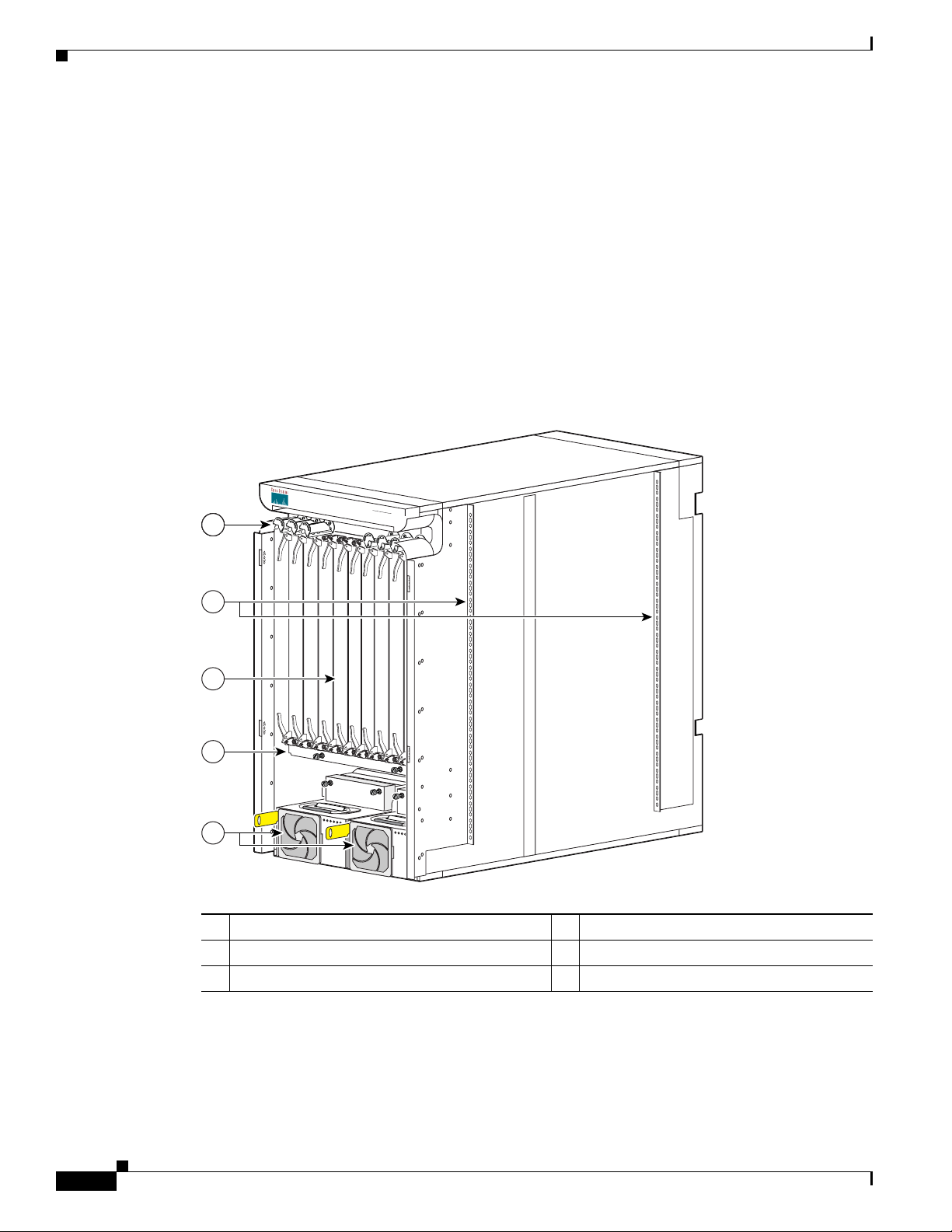
Figure 1-1 Front (PLIM) View of the 8-Slot Line Card Chassis
“Equipment Rack Considerations” section on
Chapter 1 Cisco CRS-1 Carrier Routing System
CISCO CRS-1
S
E
R
I
E
S
L
I
N
E
C
A
R
D
C
H
A
S
S
I
S
1
2
3
4
O
T
L
L
M
C
B
A
C
F
L
T
T
M
P
P
O
W
F
E
A
R
I
L
O
5
K
O
T
L
L
M
C
B
A
C
F
L
T
T
M
P
P
O
W
F
E
A
R
I
L
O
K
1 Cable management bracket 4 Air filter
2 Chassis vertical mounting brackets 5 Power modules
3 PLIM and RP slots (RPs in middle 2 slots)
122775
1-2
Cisco CRS-1 Carrier Routing System 8-Slot Line Card Chassis Site Planning Guide
OL-5802-06
Page 11
Chapter 1 Cisco CRS-1 Carrier Routing System
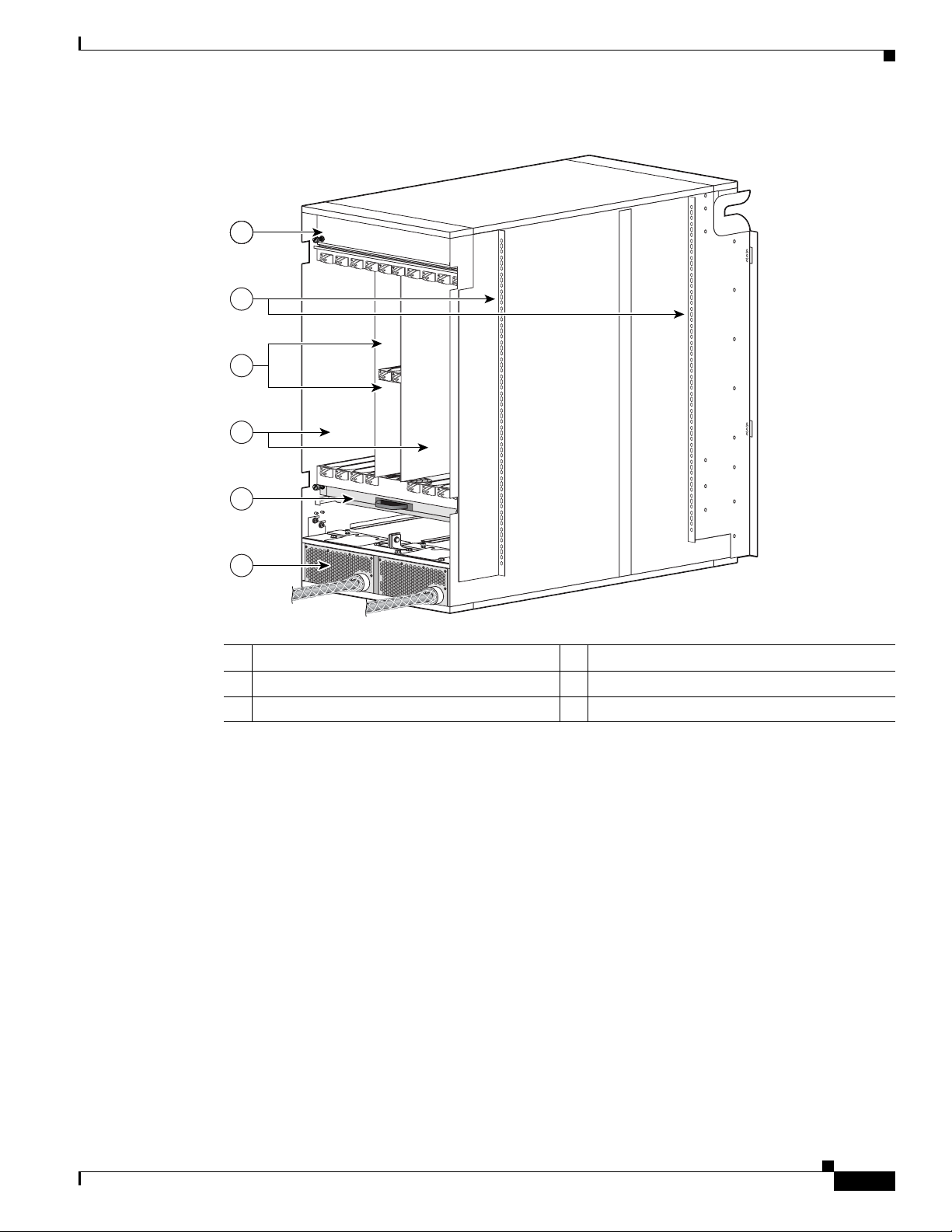
Figure 1-2 Rear (MSC) View of the 8-Slot Line Card Chassis
1
2
3
4
The Cisco CRS-1 8-Slot Line Card Chassis
5
6
1 Upper fan tray (beneath cover) 4 MSC slots
2 Chassis vertical mounting brackets 5 Lower fan tray
3 Switch fabric card (half-height) slots 6 Power distribution units (PDUs)
Chassis Components
The Cisco CRS-1 8-slot line card chassis contains the following components:
• As many as eight modular services cards (MSCs), also called line cards, and eight physical layer
interface modules (PLIMs). The MSC and PLIM are an associated pair of cards that mate through
the chassis midplane. The MSC provides the forwarding engine for Layer 3 routing of user data, and
the PLIM provides the physical interface and connectors for the user data.
The MSC can be associated with several different PLIMs, which provide different interface speeds
and technologies. The available PLIMs are as follows:
–
1-port OC-768c/STM-256c packet-over-SONET (POS). Available with short-reach (SR)
optics.
122776
OL-5802-06
–
4-port OC-192c/STM-64c POS/DPT. Available with long-reach (LR), intermediate-reach (IR),
short-reach (SR), and very-short-reach (VSR) optics.
–
OC-48c/STM-16c POS/DPT, configurable with 1 to 16 ports. Available with long-reach (LR)
and short-reach
(SR) optics. This PLIM supports pluggable optics.
Cisco CRS-1 Carrier Routing System 8-Slot Line Card Chassis Site Planning Guide
1-3
Page 12

The Cisco CRS-1 8-Slot Line Card Chassis
–
10-Gigabit Ethernet (GE. Available in long-reach (LR) optics. This PLIM supports pluggable
optics, and can be configured with 1 to 8 ports.
–
Cisco CRS-1 SPA Interface Processor-800. Occupies one physical-layer-interface-module
(PLIM) slot on the Cisco CRS-1 16- and 8-Slot Line Card Chassis. Supports six normal-height
SPAs or three double-height SPAs or any combination in between.
• A chassis midplane. The midplane connects MSCs to their associated PLIMs and allows an MSC to
be removed from the chassis without having to disconnect the cables that are attached to the
associated PLIM. The midplane distributes power, connects the MSCs to the switch fabric cards,
and provides control plane interconnections. The midplane is not field replaceable by the customer.
• One or two route processor cards (RPs). The RPs provide the intelligence of the system by
functioning as the line card chassis system controller and providing route processing. Only one RP
is required for system operation. For redundant operation, you can order a second, redundant RP as
an option (CRS-8-RP/R). When two RPs are used, only one RP is active at a time. The second RP
acts as a “standby” RP, serving as a backup if the active RP fails.
The RP also monitors system alarms and controls the system fans. LEDS on the front panel indicate
active alarm conditions.
• Upper and lower fan trays. The fans pull cool air through the chassis. A removable air filter is
located below the PLIM card cage at the front of the chassis. Each fan tray contains three fans.
Chapter 1 Cisco CRS-1 Carrier Routing System
• Four half-height switch fabric cards. These cards provide the three-stage Benes switch fabric
(S1/S2/S3) for the routing system. The switch fabric performs the cross-connect function of the
routing system, connecting every MSC (and its associated PLIM) with every other MSC (and its
associated PLIM) in the system.
The switch fabric receives user data from one MSC and PLIM pair and performs the switching
necessary to route the data to the appropriate egress MSC and PLIM pair. The switch fabric is
divided into eight planes that evenly distribute the traffic across the switch fabric. Each switch fabric
card implements two planes of the switch fabric.
• A power system that provides redundant power to the chassis. The power system consists of two
AC
or DC power distribution units (PDUs) and two AC rectifier modules or two DC power entry
modules (PEMs), one for each PDU. Each PDU supplies input power to a rectifier or PEM, which
in turn provides processed power to the chassis. Each DC and AC power module contains a
removable air filter, located on the back of the module.
The PLIM side of the chassis is considered the front of the chassis, where user data cables attach to the
PLIMs and cool air enters the chassis. The MSC side, which is where warm air is exhausted, is
considered the rear of the chassis.
Chassis Slot Numbers
The following figure shows the slot numbers on the front and back of the chassis.
1-4
Cisco CRS-1 Carrier Routing System 8-Slot Line Card Chassis Site Planning Guide
OL-5802-06
Page 13
Chapter 1 Cisco CRS-1 Carrier Routing System
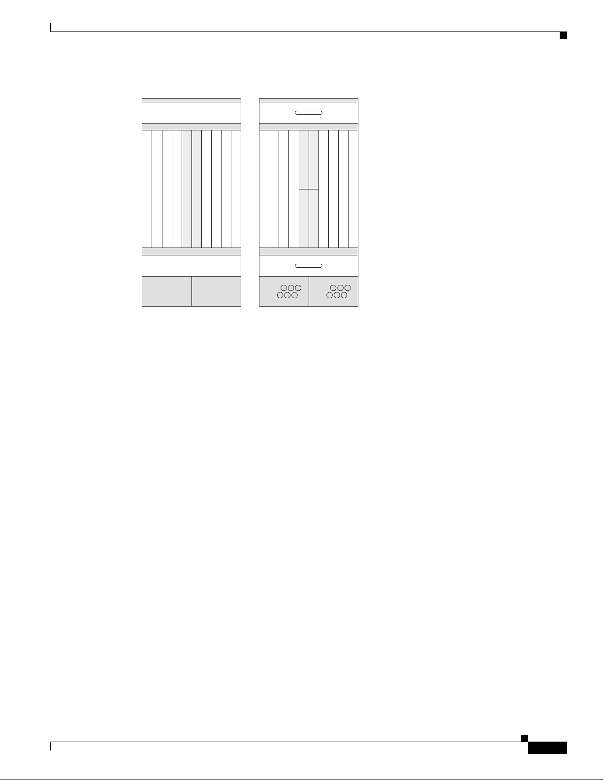
Figure 1-3 Cisco CRS-1 8-Slot Line Card Chassis Slot Numbers
The Cisco CRS-1 8-Slot Line Card Chassis
FAN 0
0123RP 0
RP 14567
7654SM 0 SM 2
SM 1 SM 33210
FAN 1
122777
As shown, the front (PLIM) side of the chassis has the following card slots:
• Eight PLIM slots (left to right: 0, 1, 2, 3...4, 5, 6, 7)
• Two route processor card slots (RP0 and RP1)
The rear (MSC) side of the chassis has the following card slots:
• Eight MSC slots (left to right: 7, 6, 5, 4...3, 2, 1, 0)
• Four half-height switch fabric card slots (SM0, SM1, SM2, and SM3)
Notice that the PLIM and MSC slot numbers are reversed. This reversal is because each MSC mates with
its associated PLIM through the midplane. For example, the PLIM in slot 0 (far left on the chassis front)
mates through the midplane with the MSC in slot 0 (far right on the chassis rear).
OL-5802-06
Cisco CRS-1 Carrier Routing System 8-Slot Line Card Chassis Site Planning Guide
1-5
Page 14

The Cisco CRS-1 8-Slot Line Card Chassis
Chapter 1 Cisco CRS-1 Carrier Routing System
1-6
Cisco CRS-1 Carrier Routing System 8-Slot Line Card Chassis Site Planning Guide
OL-5802-06
Page 15

CHA PTER
2
Power and Cooling
This chapter describes the Cisco CRS-1 Carrier Routing System 8-Slot Line Card Chassis power and
cooling systems. It also provides the power and grounding and cooling requirements for the installation
site to help you plan the site facilities for the system. The Cisco
Line Card Chassis System Description provides detailed information about these components.
This chapter contains the following sections:
• Chassis Power System
• General Power and Grounding Requirements
• DC Power Requirements
• AC Power Requirements
• Supplemental Bonding and Grounding
• Chassis Airflow
• Facility Cooling Requirements
CRS-1 Carrier Routing System 8-Slot
Chassis Power System
The 8-slot line card chassis can be either DC or AC powered. Each type of power system (DC or AC)
provides power to chassis components. The chassis power system is made up of two input power
distribution units (PDUs) and two power modules, one in each PDU. Each PDU is connected to a
different power source. Input power enters the PDU and is passed to the power module, which provides
7,500 watts of power to the components in the chassis. Each power module has its own circuit breaker.
The Cisco CRS-1 8-slot line card chassis uses the AC power PDUs to provide the two types of AC wiring
schemes (Wye and Delta). Each chassis has two PDUs, and each PDU takes one supply which, in the
case of AC, has three internal zones such that two three-zone power supplies provide three redundant
power zones (see the Cisco CRS-1 Carrier Routing System 8-Slot Line Card Chassis System Description
for more information).
Because each PDU is connected to a separate and independent power source, the power system provides
2N power redundancy. During normal operation when both power sources are operational, both sets of
PDUs and power modules function together to power the chassis. However, if a power sources fails, the
other power source provides the other PDU and power module with enough input power to power the
chassis. This 2N power redundancy enables the routing system to operate despite the power failure.
Chassis input power requirements are as follows:
• A DC-powered chassis requires 8,000 watts of DC input power.
OL-5802-06
Cisco CRS-1 Carrier Routing System 8-Slot Line Card Chassis Site Planning Guide
2-1
Page 16

General Power and Grounding Requirements
• An AC-powered chassis requires 8,750 watts of AC input power.
Note These power requirements are for a fully loaded chassis with eight PLIMs. A chassis with six or
seven
PLIMs uses slightly less power. However, it is a good idea to allocate this much power for each
chassis to ensure that enough power is available for future system expansion.
See the Cisco CRS-1 Carrier Routing System 8-Slot Line Card Chassis System Description for detailed
information about how each power system operates and distributes power to components in the chassis.
General Power and Grounding Requirements
This section describes the power and grounding requirements you must consider when planning the site
facilities for the routing system. In addition, see the
the “AC Power Requirements” section on page 2-6 for additional information about the power
requirements for your chassis type.
“DC Power Requirements” section on page 2-3 or
Chapter 2 Power and Cooling
Note A qualified electrician should review the information in these sections to ensure that the installation site
meets these requirements. For larger system configurations, you may want to consult a facilities
electrical expert to understand the load that the routing system may put on the facility power plant.
• Installation of the routing system must follow national and local electrical codes:
• In the United States: United States National Fire Protection Association (NFPA) 70 and United
States National Electrical Code (NEC).
• In Canada: Canadian Electrical Code, part I, CSA C22.1.
• In other countries: International Electrotechnical Commission (IEC) 60364, parts 1 through 7.
• Two separate and independent AC or DC power sources are needed to provide 2N redundancy for
system power. Each power source requires its own circuit breaker.
• Each power source must be providing clean power to the site. If necessary, install a power
conditioner.
• The site must provide short-circuit (over-current) protection for devices.
• Proper grounding is required at the site to ensure that equipment is not damaged by lightning and
power surges. In addition:
• For AC-powered systems, a grounding-type AC power outlet is required.
• For DC-powered systems, each DC PDU requires a connection to earth ground.
• When planning the power for the site, be sure to include the power requirements for any external
terminals and test equipment you will use with your system.
2-2
Note Be sure to review the safety warnings in Regulatory Compliance and Safety Information for the Cisco
CRS-1 Carrier Routing System before attempting to install the routing system.
Cisco CRS-1 Carrier Routing System 8-Slot Line Card Chassis Site Planning Guide
OL-5802-06
Page 17

Chapter 2 Power and Cooling
DC Power Requirements
A DC-powered line card chassis contains two DC-input power distribution units (PDUs) and two DC
power entry modules (PEMs). Each DC PDU is connected to three DC power inputs and contains a single
7500-watt DC PEM that is field replaceable. Input DC power enters the PDU and is passed to the PEM,
which provides power to the components in the chassis. Each PEM has its own circuit breaker.
In addition to the requirements described in the “General Power and Grounding Requirements” section
on page 2-2, DC input power requirements are as follows:
• A DC-powered chassis requires 8,000 watts of DC input power.
• Each DC PDU requires three VDC inputs of –48/–60 VDC (nominal). The PDU accepts input
DC
power in the range –40.5 to –75 VDC.
• A DC-powered chassis requires access to the “A” and “B” power buses at the central office (CO).
This dual connectivity provides 2N power redundancy in case a power source fails.
–
One PDU should be connected to three –48/–60 VDC inputs from the central office “A” power
bus.
–
The other PDU should be connected to three –48/–60 VDC inputs from the “B” power bus.
DC Power Requirements
• Required input current is as follows:
–
60 amps at nominal input voltage (–48/–60 VDC)
–
66 amps at low input voltage (–40.5 VDC).
• All power connection wiring must conform to the rules and regulations in the National Electrical
Code
(NEC) and any local codes. In addition, make sure that the wiring conforms to any internal
requirements at the installation site.
• Each DC power source must comply with the safety extra-low voltage (SELV) requirements in
UL
60950-1, CSA-C22.2 No. 60950-1, EN60950-1, AS/NZS 60950, and IEC60950-1.
• A DC-powered system should be installed in a restricted access area in accordance with the
National
• All components in the area where DC input power is accessible must be properly insulated.
• A readily accessible two-pole disconnect device must be incorporated in the fixed wiring, unless it
Electric Code, ANSI/NFPA 70.
is possible to rely on the identification of the power return conductor that is earth-grounded in the
DC power system.
DC Input Power and Ground Cables
Each PDU has three sets of double-stud terminals (RTN, –48V/–60V) for connecting DC input power.
To
provide 2N power redundancy, one PDU should be connected to the central office “A” power bus
and the other PDU should be connected to the “B” power bus.
OL-5802-06
The requirements for the DC input power and ground connections are as follows:
• For DC input power cables, select the appropriate wire gauge based on the National Electrical
Code
(NEC) and local codes for 60-amp service at nominal DC input voltage (–48/–60 VDC).
Three
pairs of cable leads, source DC (–) and source DC return (+), are required for each PDU.
These
cables are available from any commercial cable vendor. All input power cables for the chassis
should have the same wire gauge and cable lengths should match within 10 percent of deviation.
Cisco CRS-1 Carrier Routing System 8-Slot Line Card Chassis Site Planning Guide
2-3
Page 18

DC Power Requirements
Chapter 2 Power and Cooling
Each DC input power cable is terminated at the PDU by a cable lug. The cable lugs must be
dual-hole, and have a 45-degree angle tongue. They must be able to fit over 1/4-inch terminal studs
at 0.625-inch (15.88-mm) centers. For example, you could terminate a 2-AWG power cable with a
cable lug, such as Panduit part number LCC2-14AWH-Q (Cisco part number 32-0677-01) or
equivalent (see
Note To avoid hazardous conditions, all components in the area where DC input power is
accessible must be properly insulated. Therefore, before installing the DC cable lugs, be sure
to insulate the lugs according to the manufacturer’s instructions.
Figure 2-1 DC Input Power Cable Lug
Ø 0.27
0.60
2 holes
Figure 2-1).
All measurements in inches
2.38
0.25 0.38
0.63
1.16
1.44
45˚
.10
2.38
129535
Note DC input power cables must be connected to the PDU terminal studs in the proper positive
(+) and negative (–) polarity. In some cases, the DC cable leads are labeled, which is a
relatively safe indication of the polarity. However, you must verify the polarity by
measuring the voltage between the DC cable leads. When making the measurement, the
positive (+) lead and the negative (–) lead must always match the (+) and (–) labels on the
PDU.
• An earth ground cable is required for each DC PDU. We recommend that you use at least 6-AWG
multistrand copper wire. This wire is not available from Cisco Systems; it is available from any
commercial cable vendor.
2-4
The ground wire cable lug should be dual-hole (as shown in Figure 2-2) and able to fit over M6
terminal studs at 0.625-inch (15.88-mm) centers (for example, Panduit part number LCD6-14A-L
or
equivalent).
Cisco CRS-1 Carrier Routing System 8-Slot Line Card Chassis Site Planning Guide
OL-5802-06
Page 19

Chapter 2 Power and Cooling
Figure 2-2 DC Earth Ground Cable Lug
DC Power Requirements
All measurements in inches
2.24
End View
0.08
Ø 0.267
2 holes
Crimp area
0.25 0.370.63
25527
0.48
Figure 2-3 shows the DC input power cables connected to the DC PDU terminal studs.
Figure 2-3 DC PDU Power Cable Connections
1
129533
OL-5802-06
1 Each set of cables (RTN and –48V/–60V) is a single VDC input.
Note When wiring the PDU, be sure to attach the ground wire first (shown above on the far left side of PDU).
When removing the wiring, be sure to remove the ground wire last.
Note The power wire and ground wire connector screws have a 20 in.-lb torque value. The mounting screws
have a 9 in.-lb torque value.
The color coding of the DC input power cable leads depends on the color coding of the site DC power
source. Typically, green or green and yellow indicates that the cable is a ground cable. Because there is
no color code standard for the source DC wiring, you must ensure that the power cables are connected
to the PDU terminal studs in the proper positive (+) and negative (–) polarity.
Cisco CRS-1 Carrier Routing System 8-Slot Line Card Chassis Site Planning Guide
2-5
Page 20

AC Power Requirements
Caution Although reverse polarity should not damage the DC power system, you should correct a reverse polarity
condition immediately.
AC Power Requirements
An AC-powered line card chassis contains two AC power distribution units (PDUs) and two AC rectifier
modules. Each AC PDU is connected to an input AC power source and holds a single 7500-watt AC
rectifier. Input AC power enters the PDU and is passed to the rectifier. Here, the input AC power is
converted into the 54.5 VDC used to power components in the chassis. Each AC rectifier is field
replaceable and has its own circuit breaker.
Two versions of the AC PDU are available to accommodate AC input power in either the Delta or Wye
configuration. Each PDU has a different Cisco part number, and ships with an AC power cord that is
14
feet (4.3 m) long.
In addition to the requirements in the “General Power and Grounding Requirements” section on page 2-2,
AC input power requirements are as follows:
Chapter 2 Power and Cooling
• An AC-powered chassis (Wye or Delta) requires 8,750 watts of AC input power.
• Two separate and independent AC power sources are required, one for each PDU. Each PDU should
be connected to a different power source to provide 2N power redundancy in case a power source
fails.
• Each AC power source must provide 3-phase VAC power, and have its own circuit breaker.
• AC Delta input:
–
3-phase, 200 to 240 VAC (phase-to-phase), 50 to 60 Hz.
–
Input current: 30 A. The PDU is rated for 24-amp service, and accepts AC input of 30 A.
–
The Delta power cord has a 4-pin NEMA L15-30P plug (3 wire + protective earthing1
[3W+PE]). The
power cord is rated for 250 VAC, 30 A, and plugs into a similarly rated NEMA
L15-30R locking-type receptacle.
• AC Wye input:
–
3-phase, 200 to 240 VAC (phase-to-neutral), 50 to 60 Hz.
–
Input current: 16 A (International) or 20 A (North America). The PDU is rated for 14-amp service,
and accepts AC input of 16 or 20
–
The Wye power cord has a 5-pin IEC 60309 plug (3 wire + neutral + protective earthing
conductor (ground wire) [3W+N+PE]). The cord is rated for 400 VAC, 16 or 20
into a similarly rated IEC
• A grounding-type AC power outlet is required. The PDUs are shipped with AC power cords that
60309 receptacle.
A.
A, and plugs
have a grounding-type plug. As a safety feature, the plugs fit only a grounding-type AC power
outlet.
2-6
Cisco CRS-1 Carrier Routing System 8-Slot Line Card Chassis Site Planning Guide
OL-5802-06
Page 21

Chapter 2 Power and Cooling
Figure 2-4 AC Wye Power Cord Plug
AC Power Requirements
Figure 2-5 AC Delta Power Cord Plug
For detailed AC power specifications, see the “Line Card Chassis Specifications” section on page 3-1.
In addition, the next section “AC PDU Wiring” describes the 3-phase wiring for AC Delta and Wye
configurations.
AC PDU Wiring
This section contains a brief description of the 3-phase wiring for AC Delta and Wye configurations that
facilities electricians should understand.
AC Delta and AC Wye are both basically 200 to 240 VAC input power:
• AC Delta 3-phase wiring is typically used in the United States, Japan, and other countries where the
To AC outlet
To AC outlet
116877
116876
phase-to-neutral voltage is approximately 120 VAC and 208 VAC phase to phase.
• AC Wye 3-phase wiring is typically used in Europe and countries where each phase-to-neutral
voltage is approximately 220 VAC.
AC Delta 3-Phase Wiring
Figure 2-6 shows a PDU wired for AC Delta 3-phase power. As shown, input AC power is routed to three
internal 2.5-kW power modules in the rectifier, where it is converted into DC power (nominal 54.5 VDC,
46 ADC) and routed to the three load zones of the chassis.
The AC Delta PDU is shipped with a 14-foot (4.3 m) AC power cord with a 4-pin L15-30P plug.
OL-5802-06
Cisco CRS-1 Carrier Routing System 8-Slot Line Card Chassis Site Planning Guide
2-7
Page 22

AC Power Requirements
Chapter 2 Power and Cooling
Figure 2-6 AC Delta PDU Wiring
Plugs into L15-30R receptacle
200 to 240 VAC, 30 A, 3-phase
AC Wye 3-Phase Wiring
Figure 2-7 shows a PDU wired for AC Wye 3-phase power. As shown, input AC power is routed to
three internal 2.5-kW power modules in the rectifier, where it is converted into DC power (nominal
54.5
VDC, 46 ADC) and routed to the three load zones of the chassis.
The AC Wye PDU is shipped with a 14-foot (4.3 m) AC power cord. The power cord has a 5-pin IEC
60309 plug that is rated for 16 A (International) and 20 A (North America). It plugs into an IEC 60309
receptacle (16 or 20 A).
Figure 2-7 AC Wye PDU Wiring
Phase XPhase X
Phase Y
Phase Z
Safety Ground
2.5-kW
power
module
No. 1
2.5-kW
power
module
No. 3
2.5-kW
power
module
No. 2
122782
Plugs into IEC 60309 receptacle,
200 to 240 VAC (phase-to-neutral),
20 A (North America) 16 A (International), 3-phase
Phase XPhase X
Phase Y
Phase Z
Neutral
Safety Ground
Cisco CRS-1 Carrier Routing System 8-Slot Line Card Chassis Site Planning Guide
2-8
2.5-kW
power
module
No. 1
2.5-kW
power
module
No. 3
module
No. 2
2.5-kW
power
122783
OL-5802-06
Page 23

Chapter 2 Power and Cooling
Supplemental Bonding and Grounding
The 8-slot line card chassis has a safety earth ground connection as part of the power cabling to the
PDUs. The chassis also has supplemental bonding and grounding points (two threaded ground inserts)
that you can use to connect the router to the central office ground system or interior equipment grounding
system. Also referred to as the network equipment building system (NEBS) bonding and grounding stud,
these grounding points are located at the rear (MSC side) of the chassis (see
Note The NEBS bonding and grounding points are intended to satisfy the Telcordia NEBS requirements for
supplemental bonding and grounding connections. If you are not installing the router in a NEBS
environment, you can skip these guidelines and rely on the safety earth ground connection for the PDUs.
Figure 2-8 NEBS Bonding and Grounding Points (Rear of Chassis)
1
Supplemental Bonding and Grounding
Figure 2-8).
122792
1 NEBS bonding and grounding points
To connect the chassis to a supplemental ground connection, you must have the following:
• A grounding lug that has two M6 bolt holes with 0.625- to 0.75-inch (15.86- to 19.05-mm) spacing
between them, and a wire receptacle large enough to accept a 6-AWG or larger multistrand copper
wire. The lug is not available from Cisco Systems; it is available from electrical-connector vendors.
• Two M6 or equivalent hex-head bolts with locking washers and nuts (nickel-plated brass is ideal).
These bolts, locking washers, and nuts are not available from Cisco Systems; they are available from
any commercial hardware vendor.
• A grounding wire. Although we recommend at least 6-AWG multistrand copper wire, the actual
wire diameter and length depend on your router location and site environment. This wire is not
available from Cisco Systems; it is available from any commercial cable vendor.
Caution The DC Return of the Cisco CRS-1 8-slot chassis should remain isolated from the system frame and
chassis (DC-I: Isolated DC Return).
OL-5802-06
For additional information about NEBS, see Cisco CRS-1 Carrier Routing System Regulatory
Compliance and Safety Information.
Cisco CRS-1 Carrier Routing System 8-Slot Line Card Chassis Site Planning Guide
2-9
Page 24

Chassis Airflow
Chassis Airflow
The Cisco CRS-1 8-slot line card chassis has two fan trays, with three fans each, that cool the chassis
card cages. Cool air flows in at the bottom front of the chassis and flows through the chassis card cages
and through the fans in the fan trays before being exhausted through the bottom rear of the chassis (see
Figure 2-9).
In addition, each AC or DC power module at the bottom of the chassis has self-contained fans that pull
in cool air from the front of the chassis and exhaust warm air out the rear.
A replaceable air filter is located on the front of the chassis below the PLIM card cage. Each power
module also has a replaceable air filter that attaches to the module at the front side of the chassis. How
often you should replace the air filters depends on the facility environment.
In a dirty environment or when you start getting frequent temperature alarms, you should always check
the intake grills for debris, and then check the air filters to see if they need to be replaced.
Note We recommend that you check the air filters once a month. Replace a filter when you notice a significant
amount of dust.
Chapter 2 Power and Cooling
Figure 2-9 Airflow Through the 8-Slot Line Card Chassis
Front Rear
Fan
Air filter
Air enters
PLIM side
Power system
Fan
Air exits MSC and
fabric card side
The 8-slot line card chassis airflow volumes are as follows:
• Chassis airflow: Up to 900 cubic feet (25,485 liters) per minute
• Power system airflow: Up to 240 cubic feet (6800 liters) per minute
122784
Facility Cooling Requirements
The 8-slot line card chassis dissipates considerable power that generates much heat. In large
configurations, additional air cooling is required to maintain correct operating temperatures. The room
air must be cooled by external cooling units that are installed as part of the routing system.
Cisco CRS-1 Carrier Routing System 8-Slot Line Card Chassis Site Planning Guide
2-10
OL-5802-06
Page 25

Chapter 2 Power and Cooling
Heat dissipation and external cooling requirements for the 8-slot line card chassis are as follows:
• Heat dissipation: 27,350 BTUs per hour
• External cooling requirements: 2.3 tons
To ensure that the site provides the proper air circulation for the system:
• Make certain that the site is as dust free as possible. Dusty environments can clog the air filter or
• Allow sufficient airflow by maintaining a minimum of 6 inches (15.2 cm) of clearance at both the
Facility Cooling Requirements
power supply intake vents, reducing the cooling airflow through the system.
inlet and exhaust openings on the chassis and the power modules. If airflow is blocked or restricted,
or if inlet air is too warm, an over-temperature condition can occur. Under extreme conditions, the
environmental monitoring system shuts down the power to protect the routing system components.
OL-5802-06
Cisco CRS-1 Carrier Routing System 8-Slot Line Card Chassis Site Planning Guide
2-11
Page 26

Facility Cooling Requirements
Chapter 2 Power and Cooling
2-12
Cisco CRS-1 Carrier Routing System 8-Slot Line Card Chassis Site Planning Guide
OL-5802-06
Page 27

Technical and Environmental Specifications
This chapter summarizes the technical and environmental specifications for the Cisco CRS-1 Carrier
Routing System 8-Slot Line Card Chassis. It includes the following sections:
• Line Card Chassis Specifications
• Equipment Rack Specifications
• Environmental Specifications
Line Card Chassis Specifications
The following table lists the system specifications for the Cisco CRS-1 8-slot line card chassis.
Ta b l e 3-1 8-Slot Line Card Chassis Component and Power Specifications
Supported Cards and Modules
8 modular services cards (MSCs)
CHA PTER
3
8 physical layer interface modules (PLIMs),
one for each MSC
4 switch fabric cards (SFCs)
2 route processors (RPs)
1 distributed route processor (DRP)
2 fan trays (with three fans per fan tray)
1 air filter
Power Distribution Units
DC PDU Supports 1 DC power entry module (PEM)
AC PDU Supports 1 AC rectifier module
Maximum Power Consumption
(total input power)
Maximum DC 8.0 kW
Maximum AC 8.75 kW (Delta or Wye 3-phase)
2 AC (Wye or Delta) or 2 DC power distribution units
(PDUs)
(cannot mix AC and DC PDUs in the chassis)
OL-5802-06
Cisco CRS-1 Carrier Routing System 8-Slot Line Card Chassis Site Planning Guide
3-1
Page 28

Equipment Rack Specifications
Table 3-1 8-Slot Line Card Chassis Component and Power Specifications (continued)
Power Redundancy (2N)
DC Three “A” battery plant feeds required for one PDU,
AC (Delta or Wye 3-phase) Two independent Delta or Wye 3-phase power sources
DC Input
Nominal input voltage –48 VDC North America
Input current 60 A at –48/–60 VDC (nominal voltage)
AC Input, Delta 3-phase
Input voltage 3-phase 200 to 240 VAC, phase-to-phase (nominal)
Line frequency 50 to 60 Hz
Input current
(PDU rated for 24 A)
AC Input, Wye 3-phase
Input voltage 3-phase 200 to 240 VAC, phase-to-neutral (nominal)
Line frequency 50 to 60 Hz (nominal)
Input current
(PDU rated for 14 A)
Chapter 3 Technical and Environmental Specifications
Note Proper grounding is also required at the site to
ensure that equipment is not damaged by
lightning or power surges.
and three “B” battery plant feeds required for the other
PDU.
required, one for each PDU.
–54 VDC Telco (RBOC)
–60 VDC International
(range –40.5 to –75 VDC)
66 A at –40.5 VDC (low voltage extreme)
3W + PE (3 wire + protective earthing conductor
ground wire)
(range 170 to 264 VAC, phase-to-phase)
(range 47 to 63 Hz)
30 A
3W + N + PE (3 wire + neutral + protective earthing
conductor ground wire)
(range 170 to 264 VAC, phase-to-neutral)
(range 295 to 457 VAC, phase-to-phase)
(range 47 to 63 Hz)
16 A International
20 A North America
Equipment Rack Specifications
Cisco Systems has tested the Cisco CRS-1 8-slot line card chassis to Cisco internal mechanical design
verification testing and electrical design verification testing in an Enclosure Systems Worldwide ESW
27 rack (part
particular rack product. The Cisco
information. Use this information for planning only. Consult your Cisco account representative for
additional details.
Cisco CRS-1 Carrier Routing System 8-Slot Line Card Chassis Site Planning Guide
3-2
number F-01941-01). This finding is neither an endorsement nor recommendation for any
CRS-1 product documentation will be updated with additional
OL-5802-06
Page 29

Chapter 3 Technical and Environmental Specifications
If you plan to install the chassis in your own four-post rack, make sure that the rack meets the
specifications summarized in
Ta b l e 3-2 8-Slot Line Card Chassis and Equipment Rack Specifications
8-Slot Line Card Chassis Specifications
Chassis Dimensions
Height 38.5 in. (97.8 cm)
Width 17.5 in. (44.5 cm)
Depth 36.6 in. (93.0 cm) without cosmetics
Chassis Weight
Chassis shipping weight 418.3 lb (189.7 kg) chassis with shipping crate and pallet
Chassis with all cards and
power modules, no cosmetics
Chassis, fully loaded with line
cards and full cosmetics (doors,
panels, grilles, and so on)
Equipment Rack Specifications
Rack Dimensions
Equipment Rack Specifications
Table 3-2.
18.9 in. (48.0 cm) mounting rail flange, outside to outside
40.5 in. (102.9 cm) with full cosmetics and front and rear doors
330.8 lb (138 kg) chassis with fans, PDUs, and blanks (as shipped)
600 lb (272.2 kg)
650 lb (294.8 kg)
Height Available aperture in rack for two chassis in a single rack:
• 78.6 in. (199.6 cm)
Width Vertical posts:
• 19.5 in. (49.5 cm) inside-to-inside minimum
• 23.6 in. (60.0 cm) outside-to-outside maximum
Depth Exterior of four-post rack:
• Optimal: 27 in. (68.6 cm), for best access to mounting hardware
• Optional: 30, 36, or 42 in. (76.2, 91.4, or 106.7 cm) and other
standard depths allowed, allow less space for cable management
Equipment Rack Specifications (continued)
OL-5802-06
Cisco CRS-1 Carrier Routing System 8-Slot Line Card Chassis Site Planning Guide
3-3
Page 30

Equipment Rack Specifications
Table 3-2 8-Slot Line Card Chassis and Equipment Rack Specifications (continued)
Load (weight) rating The rack must support the following weights and specifications:
Chassis and rack footprint
(floor contact area)
Maximum floor loading 600 lb/4.5 sq. ft = 133 lb/sq. ft (without cosmetics or doors)
Chapter 3 Technical and Environmental Specifications
• 650 lb (294.8 kg) single chassis with full cosmetics
• 1300 lb (589.7 kg) two chassis, each with full cosmetics
• 95 lb (43.0 kg) or more for each chassis for cabling
• Additional weight of other components in rack
Note ANSI specification T1.336 (2003), which defines static load
and safety margins, recommends that racks be designed to
support at least two times the anticipated load.
Note See ANSI specification T1.329 (2002) for dynamic load
requirements and earthquake resistance specifications.
5.9 sq. ft (0.55 sq. m), 23.6 in. rack width by 36 in. chassis length
272.2 kg/4134.2 sq. cm = .07 kg/sq. cm
650 lb/4.9 sq. ft = 132.7 lb/sq. ft (with cosmetics and doors)
294.8 kg/4580.1 sq. cm = .06 kg/sq. cm
Note Be sure to include the weight of the rack when you consider
floor loading requirements. The above numbers do not
include rack weight.
Rack Anchoring
General considerations • The rack must be bolted to the floor. For more information, see
the Cisco CRS-1 Carrier Routing System Line Card Chassis
Unpacking, Moving, and Securing Guide.
• Consider floor and overhead anchoring requirements for the site,
and size and load capacity of anchors and floor structure.
• Make sure that floor mounting bolts are accessible, especially if
annual retorquing of bolts is required.
Floor mounting holes • Outrigger L-brackets:
20.1-inch (51.0 cm) wide x 31.6-inch (80.3 cm) deep
• Internal frame holes:
17.625-inch (44.77 cm wide) x 21-inch (53.34 cm) deep
• For all other racks, check with rack manufacturer.
Chassis Clearances
Two chassis in a single rack 0.5-inch (1.27 cm) between chassis for horizontal shelf brackets
Front and rear of chassis 40.4-inch (102.6 cm) for chassis installation
36-inch (91.4 cm) for service access and airflow
Inlet and exhaust openings on
6-inch (15.2 cm)
chassis and power modules
Top of chassis No overhead clearance for a single chassis. Two chassis in a rack
requires 0.5-inch (1.27 cm) between chassis for mounting rails.
3-4
Cisco CRS-1 Carrier Routing System 8-Slot Line Card Chassis Site Planning Guide
OL-5802-06
Page 31

Chapter 3 Technical and Environmental Specifications
Table 3-2 8-Slot Line Card Chassis and Equipment Rack Specifications (continued)
Equipment Rack Specifications (continued)
Mounting Rails and Hardware
Rail openings (aperture) • 17.75 in. (45.1 cm), side to side
Horizontal mounting rails The equipment rack should contain horizontal mounting rails to
Mounting holes EIA standard mounting-hole spacing:
Equipment Rack Specifications
• 22.8 in. (57.9 cm), front to back (adjustable or fixed)
place the chassis on. The mounting rails, which must be able to hold
at least 650
• ESW 27 racks are equipped with horizontal mounting rails
already installed. Place the chassis on these rails.
• For other types of racks, a set of brackets is included in the
chassis installation kit, which is available as an option
(CRS-8-INSTALL-KT=). Install these brackets and place the
chassis on them. For details, see the Cisco CRS-1 Carrier
Routing System Line Card Chassis Unpacking, Moving, and
Securing Guide.
Note In addition to supporting the chassis, the mounting rails are
lb (294.8 kg), support the weight of the chassis.
also designed to space adjustable rack rails at 22.8-inches (front
to back) for chassis installation.
• 18.25-inches to 18.31-inches (46.36 to 46.51 cm),
center-to-center horizontal spacing
• 0.5 + 0.625 + 0.625-inches (1.27 + 1.59 + 1.59 cm),
vertical-hole-spacing pattern; repeats on 1.75-inch (4.45 cm)
pitch ETSI racks have mounting rails with EIA standard
spacing.
Mounting screws • 48 screws for each chassis, 12 screws in each of 4 vertical rails,
installed in holes with tick marks
• No. 10-32 screws (provided with the chassis)
• No. 10-24 or M5 screws can be used if rack thread pitch allows.
Note If you plan to use mounting screws other than the ones
shipped with the chassis, make sure that the screws are made
of stainless steel or a hard alloy. Do not use screws made of
soft
alloy steel.
Compliance
Make sure that the rack complies with all appropriate standards for
your geographical area—for example, NEBS Seismic Zone 4
(GR-63-CORE, Sections 4.4.1 and 4.4.2).
Note The 8-slot chassis has passed Cisco Zone 4 seismic testing in
an ESW 27 rack (part
Additional Rack Considerations
number F-01941-01).
Interface cables When choosing a rack, consider cabling needs (chassis front). Allow
at least 95 lb (43.1 kg) weight for each chassis for cables.
OL-5802-06
Cisco CRS-1 Carrier Routing System 8-Slot Line Card Chassis Site Planning Guide
3-5
Page 32

Environmental Specifications
Environmental Specifications
The following table lists the environmental specifications for the Cisco CRS-1 8-slot line card chassis.
Ta b l e 3-3 8-Slot Line Card Chassis Environmental Specifications
Description Value
Temperature Operating, nominal: 41° to 104°F (5° to 40°C)
Operating, short-term: 23° to 122°F (–5° to 50°C)
Nonoperating: –40° to 158°F (–40° to 70°C)
Humidity Operating: 5 to 85% noncondensing
Nonoperating: 5 to 90% noncondensing, short-term operation
Altitude 1 to 5906 ft (–60 to 1800 m) at 122°F (50°C), short-term
Up to 13,123 ft (4000 m) at 104°F (40°C) or below
Heat dissipation 27,350 BTU per hour
Chapter 3 Technical and Environmental Specifications
External cooling
requirements
Chassis airflow Up to 900 cubic feet (25,485 liters) per minute
Power system airflow Up to 240 cubic feet (6800 liters) per minute
Acoustic noise
3.3 ft (1 m) from chassis
Shock and vibration Designed and tested to meet the NEBS shock and vibration standards
2.3 tons
76 dB—80°F (27°C) or lower (fan speed 4000 RPM)
86 dB—104°F (40°C) or higher (fan speed 6500 RPM)
90 dB—failure condition (fan speed 7500 RPM)
defined in GR-63-CORE (Issue 2, April 2002).
3-6
Cisco CRS-1 Carrier Routing System 8-Slot Line Card Chassis Site Planning Guide
OL-5802-06
Page 33

CHA PTER
4
Site Planning Considerations
This chapter describes the general considerations to address while planning for the installation of the
Cisco
CRS-1 8-Slot Line Card Chassis. It does not repeat the specifications in Chapter 3, but you should
keep those specifications in mind as you plan for your system.
This chapter includes the following sections:
• Basic Site and Installation Planning
• Tools Required for Installation
• Equipment Rack Considerations
• Aisle Spacing and Maintenance Access Floor Plan
• Power and Cooling Requirements
• System Console
• Cable Management
• Route Processor Cables
• PLIM Interface Cables
• Custom Cables
• Noise Control
• Cisco Installation Services
• System Testing, Certification, and Warranties
Basic Site and Installation Planning
As you plan for basic site and installation requirements, consider the following:
• Does the installation site have adequate power for the routing system?
• Can the routing system be positioned close to the AC or DC power source, and are the power
receptacles easy to reach?
• Does the site have appropriate equipment racks with space available in which to install the system?
Are additional equipment racks required? See the
page 3-2 for information about rack requirements.
• Is there a scissor lift or similar lifting device available to lift the chassis into the equipment rack?
In addition, make sure that the installation site meets the following access requirements:
“Equipment Rack Specifications” section on
OL-5802-06
Cisco CRS-1 Carrier Routing System 8-Slot Line Card Chassis Site Planning Guide
4-1
Page 34

Tools Required for Installation
• At least 48 inches (122 cm) of clearance exists between rows of equipment racks. This space is
needed to access components in the chassis. Additional clearance may be necessary for installation.
• Enough room exists for the system console terminal, and that the console cable is long enough to
reach the routing system from the terminal.
• Fan tray exhaust vents are not blocked, and airflow at the bottom of the chassis is not blocked.
When planning the site, you should think about potential expansion of the system. Consider the
following:
• Equipment rack space for additional chassis
• Power and cooling requirements for additional chassis
• Cable management for routing system cables
Tools Required for Installation
The following tools are required to install the Cisco CRS-1 8-Slot Line Card Chassis:
• Safety hand truck, pallet jack, or forklift to move the equipment to the installation site. Make sure
that the device is capable of preventing the router from tipping. For example, you could use a safety
hand truck with retractable safety leg wheels and a security strap, such as the Stevens Appliance
Truck Company “Escort,” Model STEV SRT-M-66 (distributed by McMaster-Carr as Model
2654T6) or an equivalent safety hand truck.
Chapter 4 Site Planning Considerations
• A scissor lift or similar lifting device to position the chassis in the rack and hold the chassis in place
while you bolt it to the rack.
• Electric screwdriver or cordless drill (optional, but helpful)
• 5/32-inch insert bit that fits 1/4-inch drive extension (preferably magnetic, and one that fits in a
cordless drill)
• 1/4-inch drive socket
• 1/4-inch drive extension and 1/4-inch drive flexible extension, length of 6 inches (15.24 cm)
• Phillips-head number 1 and number 2 screwdrivers
• 7-mm wrench or 7-mm nut driver or socket (if unavailable, use 9/32-inch standard tools)
• 8-mm wrench
• 10-mm wrench
• Crescent wrench
• 5/16-inch socket wrench
• M6 hex socket screwdriver
• Large and small socket wrenches
• Allen wrench
• Large, medium, and small Phillips screwdrivers
• Large, medium, and small flat-blade screwdrivers
• ESD-preventive wrist strap
4-2
• Antistatic mat
• Scissors
Cisco CRS-1 Carrier Routing System 8-Slot Line Card Chassis Site Planning Guide
OL-5802-06
Page 35

Chapter 4 Site Planning Considerations
• Tape measure (optional)
Equipment Rack Considerations
A fully loaded Cisco CRS-1 8-slot line card chassis weighs 650 lb (294.8 kg). The chassis is mounted
in a four-post rack. (See
To ensure safe installation and operation of the routing system, you must install the chassis in a four-post
equipment rack that meets the specifications described in the
on page 3-2.
Figure 4-1 8-Slot LIne Card Chassis Mounted in an Equipment Rack
1
Figure 4-1.)
Equipment Rack Considerations
“Equipment Rack Specifications” section
C
I
S
C
O
C
R
S
1
S
E
R
I
E
S
L
I
N
E
C
A
R
D
C
H
A
S
S
I
S
2
3
122781
1 Equipment rack 3 Vertical mounting brackets
2 8-slot line card chassis
OL-5802-06
Warning
The chassis should be mounted on a rack that is permanently affixed to the building.
Cisco CRS-1 Carrier Routing System 8-Slot Line Card Chassis Site Planning Guide
Statement 1049
4-3
Page 36

Aisle Spacing and Maintenance Access Floor Plan
Note We recommend that you use a scissor lift or similar lifting device to position the chassis in the rack and
to hold the chassis in place while you bolt it to the rack. A forklift is not recommended for this purpose.
As you plan the installation of the chassis into the equipment rack, consider the following:
• Make sure that the floor mounting bolts on the equipment rack are accessible, especially if annual
retorquing of bolts is required.
• For chassis installation, you must have access to the vertical mounting rails at each corner of the
equipment rack.
• Consider whether the area around the rack is large enough to accommodate the scissor lift (or similar
lifting device) and installation personnel.
• A minimum of 48 mounting screws (provided with the chassis) are needed to secure the chassis to
the rack. To secure the chassis to the rack, you install 12 screws in each of the four corners of the
rack.
• The rack should have horizontal shelf brackets to place the chassis on. The brackets must be able to
support at least 650 lb. (294.8 kg). If the rack does not have horizontal mounting rails, a set of rails
is included in the installation kit, which is available as an option (CRS-8-INSTALL-KT=).
Chapter 4 Site Planning Considerations
Caution Standard rack-mounting screws are not strong enough to secure the chassis to the equipment rack.
Use
only those mounting screws that are shipped with the chassis or those listed in the “Equipment Rack
Specifications” section on page 3-2.
For complete instructions on mounting and securing the chassis to a rack, see the Cisco CRS-1 Carrier
Routing System 8-Slot Line Card Unpacking, Moving, and Securing Guide.
Aisle Spacing and Maintenance Access Floor Plan
The floor plan for the Cisco CRS-1 must include enough space to install the 8-slot line card chassis in
the equipment rack and allow sufficient airflow for the system. The floor plan must also provide enough
room to access chassis components for maintenance (for example, to remove fan trays, power modules,
cables, and air filters).
Figure 4-2 shows a top view of the Cisco CRS-1 8-slot line card chassis footprint required for installation
(with optional front and rear cosmetics installed).
Note For chassis installation, make sure that enough room exists in front of the chassis to accommodate
installation personnel and the scissor lift (or similar lifting device) used to hold the chassis in the rack
while it is bolted in.
4-4
Cisco CRS-1 Carrier Routing System 8-Slot Line Card Chassis Site Planning Guide
OL-5802-06
Page 37

Chapter 4 Site Planning Considerations
Figure 4-2 Typical Cisco CRS-1 8-Slot Line Card Chassis Floor Plan
Aisle Spacing and Maintenance Access Floor Plan
Service access
area: in front
of chassis
Cisco CRS-1 8-slot
line card chassis
Service access
area: behind rear
of chassis
36 in.
(91.4 cm)
40.4 in.
(102.6 cm)
36 in.
(91.4 cm)
112.4 in.
(285.4 cm)
122051
Dimensions of the 8-Slot Line Card Chassis
The dimensions for the Cisco CRS-1 8-slot line card chassis are:
• Chassis depth (including closed (optional) front and rear doors and an installed cable management
bracket): ~35 to 40 in. (88.9 to 101.6 cm)
• Chassis height: 38.5 in. (97.8 cm)
• Chassis width: 17.5 in. (44.5 cm).
Note Because there is no external switch-fabric interconnection cabling on a single line card chassis system,
the rear door is optional.
Front and Rear Clearances
The site requires the following front and rear clearances for chassis installation and maintenance access:
• To install the chassis in the equipment rack: 40.4 inches (102.6 cm)
• To service components and allow system airflow (both in front of and behind the chassis): 36 inches
(91.4 cm)
Note Maintain at least 6 inches (15.2 cm) of clearance at both the inlet and exhaust openings on the
chassis and on the power modules to allow sufficient airflow.
OL-5802-06
Cisco CRS-1 Carrier Routing System 8-Slot Line Card Chassis Site Planning Guide
4-5
Page 38

Power and Cooling Requirements
Power and Cooling Requirements
See Chapter 2, “Power and Cooling,” for information about the power and cooling systems on the 8-slot
chassis and for information about the power and cooling requirements at the installation site.
System Console
A system console is required to configure the routing system for operation. As you plan your site
facilities, make sure that the site has enough room for a system console and the console cable is long
enough to reach the routing system.
Note The console port does not support modem control or hardware flow control. The port
requires a straight-through EIA/TIA-232 cable.
Cable Management
Chapter 4 Site Planning Considerations
As the size of the routing system increases, the cabling required for the chassis increases. For example,
a fully loaded 8-slot line card chassis has more cables connected to it than a partially loaded chassis. The
cabling runs must be carefully planned. The basic configurations for various routing systems should be
arranged to minimize the complexity and length of the cable runs. Precut and terminated cables are
considered part of the basic configuration.
• CONSOLE or AUX RJ-45 RS-232 serial ports on the route processor cards for terminal connections
• Ethernet ports on the route processor cards for connecting network management equipment
• Modular service cards (MSCs) and physical layer interface modules (PLIMs) for data connections
The cable-management bracket is for organizing these interface cables to keep the front of the chassis
clear and to eliminate sharp bends in the cables.
Caution Excessive bending can damage interface cables.
The cable-management bracket has a special telescoping feature that allows the bracket to be extended
when the chassis is upgraded with higher-density cards. This extension feature also helps in installing
the cables in the chassis.
Figure 4-3 shows the chassis cable-management bracket.
4-6
Cisco CRS-1 Carrier Routing System 8-Slot Line Card Chassis Site Planning Guide
OL-5802-06
Page 39

Chapter 4 Site Planning Considerations
Figure 4-3 Cable Management Bracket (Front of Chassis Only)
Route Processor Cables
Cable Management
101818
As you consider system cabling, see Tabl e 4-1 to determine the types of cables required to connect to
ports on the route processor (RP).
Ta b l e 4-1 Route Processor Cables
RP Port Required Cable Type
Ethernet management Shielded twisted-pair (STP) cable (Category 5 or better). Required
Alarm Shielded cable. Required for EMC compliance.
PLIM Interface Cables
You must provide the PLIM interface cables. Because the type and number of interfaces can vary, plan
these cable runs prior to the installation. When planning the cable runs, consider the following:
• Number and type of interface connections (OC-48/STM-16, OC-192/STM-64, OC-768/STM-256,
and 10-Gigabit Ethernet)
• Termination at the other end of the cables (such as patch panel or optical transport equipment)
• Proper length and termination of cables
for enhanced immunity to external electromagnetic disturbance
levels of 10 V/m and 10 Vrms.
Custom Cables
OL-5802-06
The installation site may require custom cables designed for the facilities. Cisco can assist you in
planning custom cables.
Cisco CRS-1 Carrier Routing System 8-Slot Line Card Chassis Site Planning Guide
4-7
Page 40

Noise Control
Noise Control
A routing system can generate large amounts of fan noise. The 8-slot line card chassis has some built-in
noise reduction, such as fan speed control. If the routing system is installed in an environment where
excessive noise could be harmful to personnel, some other noise reduction options could be attempted.
Passive noise reduction could include the installation of foam panels to insulate the surrounding area
from the noise.
Additional noise-reduction measures have to be designed on an individual site basis.
Cisco Installation Services
Cisco or a Cisco partner can provide a complete installation, from planning to power up. For information
about Cisco or Cisco partner installation services, consult Cisco Customer Advocacy.
System Testing, Certification, and Warranties
Chapter 4 Site Planning Considerations
After the routing system has been installed, it must be tested and certified. Consult Cisco Customer
Advocacy for information about testing, certification, and warranties.
4-8
Cisco CRS-1 Carrier Routing System 8-Slot Line Card Chassis Site Planning Guide
OL-5802-06
Page 41

Site Planning Guidelines
This appendix contains the following sections:
• Site Planning Checklist
• Preliminary Site Survey
Site Planning Checklist
Table A-1 lists the sequence of tasks to perform as you plan the installation of the routing system. Use
the table as a checklist for all aspects of the installation. For information about a particular task, see the
appropriate section of this site planning guide. After completing the checklist, you should consult your
Cisco installation coordinator for a site-readiness inspection.
Ta b l e A-1 Routing System Installation Checklist
APPENDIX
A
Site Planning Steps See Check
1. Determine where to install the routing system
and make sure that you have the appropriate
installation and configuration tools.
2. Consider equipment arrival, storage, and
transport to the installation site.
3. Make sure that the equipment rack meets the
installation requirements.
4. Consider the space where the routing system
will be installed.
5. Plan for power (AC or DC). Chapter 2, “Power and Cooling”
6. Consider cooling and airflow requirements. “Chassis Airflow” section on page 2-10
7. Consider cable management. “Cable Management” section on page 4-6
8. Consider Cisco installation services. “Cisco Installation Services” section on page 4-8
“Basic Site and Installation Planning” section on page 4-1
“Tools Required for Installation” section on page 4-2
“Basic Site and Installation Planning” section on page 4-1
“Basic Site and Installation Planning” section on page 4-1
“Equipment Rack Specifications” section on page 3-2
“Equipment Rack Considerations” section on page 4-3
“Aisle Spacing and Maintenance Access Floor Plan”
section on page 4-4
“Line Card Chassis Specifications” section on page 3-1
“Facility Cooling Requirements” section on page 2-10
“Environmental Specifications” section on page 3-6
OL-5802-06
Cisco CRS-1 Carrier Routing System 8-Slot Line Card Chassis Site Planning Guide
A-1
Page 42

Preliminary Site Survey
Preliminary Site Survey
Typically, you should complete a preliminary site survey before you plan a detailed site survey. This
preliminary survey ensures that the basic system requirements have been completed or are underway
before detailed plans for the site are completed.
Ta b l e A-2 Sample Routing System Preliminary Site Survey
Preliminary Site Survey
Order Information
Sales order number:
Estimated shipping date:
Site ready date:
Installation date:
Appendix A Site Planning Guidelines
Table A-2 is a sample preliminary site survey.
Site Location and Address
Company name:
Site address:
Shipping address:
Building or computer room access:
Special instructions:
Hours and days of operation:
Primary Contact
Name and title:
Phone number:
Mobile phone number:
Fax number:
Pager number:
E-mail address:
Site Survey Contacts
A-2
Cisco CRS-1 Carrier Routing System 8-Slot Line Card Chassis Site Planning Guide
OL-5802-06
Page 43

Appendix A Site Planning Guidelines
Table A-2 Sample Routing System Preliminary Site Survey (continued)
Preliminary Site Survey
Secondary Contact
Name and title:
Phone number:
Mobile phone number:
Fax number:
Pager number:
E-mail address:
Delivery and Installation Constraints
Is there a loading dock available to unload
the equipment at this site?
Is someone on site during working hours
to accept delivery of the materials? If not,
list the times this person is available.
Are there any special requirements for
equipment delivery (for example, special
delivery times, the need for escorts or
IDs, or safety procedures to follow, such
as hard hats, safety glasses, and so on)?
Is the path to the installation area clear? If
not, can arrangements be made to move
the equipment to the installation area?
Describe them.
What floor is the installation site on?
If it is on a floor other than the ground
floor, is there a freight elevator available?
Note whether the equipment needs to be
brought up a flight of stairs.
Preliminary Site Survey
How many chassis are being installed?
Are there equipment racks currently
available for all chassis to be installed?
Do the equipment racks meet the
installation requirements?
Make a sketch of the area where the
chassis will be installed. Determine how
many chassis (1 or 2) will be installed in
each equipment rack.
OL-5802-06
Equipment Rack Mounting
Cisco CRS-1 Carrier Routing System 8-Slot Line Card Chassis Site Planning Guide
A-3
Page 44

Preliminary Site Survey
Table A-2 Sample Routing System Preliminary Site Survey (continued)
Preliminary Site Survey
Power
Is DC or AC power available for each
chassis? Is there a connection point on the
panel for each chassis?
Is a fuse access panel (FAP) available for
the equipment? Provide a connection
point on the FAP for each chassis.
Will an FAP be installed in time for the
routing system installation? Provide a
date when the FAP will be installed.
Is the FAP located in the same room as the
chassis?
Is there an AC power outlet (220 V or
110
V) located within 10 feet of each
chassis, for PCs and test equipment?
Has proper grounding been provided for
the equipment? If not, when will the
grounding be available? Provide a
connection point for the grounding.
Are there any restrictions about when the
equipment can be powered on or when
electrical work can be done? If so,
describe them.
Are there special requirements for power
or power cables (for example, a different
gauge of wire)? If so, describe them.
Air Conditioning
Does the site have the air conditioning
capacity to handle the routing system? If
not, note what will be done to rectify the
lack of adequate cooling.
Describe the air conditioning at the site.
Appendix A Site Planning Guidelines
Will the chassis be connected to an
external alarm system? Has the cabling
been considered?
Cisco CRS-1 Carrier Routing System 8-Slot Line Card Chassis Site Planning Guide
A-4
Control Plane and Alarm Interfaces
OL-5802-06
Page 45

Appendix A Site Planning Guidelines
Table A-2 Sample Routing System Preliminary Site Survey (continued)
Preliminary Site Survey
Supported Data Interfaces
Will the routing system be connected to
OC-48/STM-16 POS circuits? How many
ports?
Will the routing system be connected to
OC-192/STM-64 POS circuits? How
many ports?
Will the routing system be connected to
OC-768/STM-256 POS circuits? How
many ports?
Will the routing system be connected to
10-Gigabit Ethernet (GE) circuits? How
many ports?
Have the cables been pulled for the data
interfaces? If not, list the outstanding
cabling that needs to be installed and the
scheduled completion dates.
Are there connection points on the fiber
distribution panel for all optical cables
connecting to the routing system?
Who will provide fiber jumpers? What
length of fiber jumper is required to
complete the installation?
What type of fiber connector is used at the
installation site?
If attenuation is required, are attenuators
available at the installation site? If not,
who will pay for the attenuators?
Cable Management
Preliminary Site Survey
OL-5802-06
Cisco CRS-1 Carrier Routing System 8-Slot Line Card Chassis Site Planning Guide
A-5
Page 46

Preliminary Site Survey
Appendix A Site Planning Guidelines
A-6
Cisco CRS-1 Carrier Routing System 8-Slot Line Card Chassis Site Planning Guide
OL-5802-06
Page 47

APPENDIX
B
Product IDs for the Cisco CRS-1 8-Slot Line Card Chassis
This appendix provides information about the product IDs for components of the Cisco CRS-1 Carrier
Routing System 8-Slot Line Card Chassis. It contains the following tables:
• Cisco CRS-1 8-Slot Line Card Chassis Component Product IDs
• Optional MSC, PLIM, SIP, and SPA Product IDs
These tables list the components that make up the routing system, their product IDs (the part numbers
to use to order the components), and descriptions.
Note Although this appendix provides product IDs for routing system components, the Cisco online ordering and
pricing tool has the most up-to-date information on the routing system and product IDs. You can access the
ordering tool at the following URL (CCO login required), and enter a search term such as “CRS” or
“CRS-1” to view a list of components:
http://www.cisco.com/cgi-bin/front.x/pricing
Cisco CRS-1 8-Slot Line Card Chassis Component Product IDs
The following table lists the product IDs for components in the Cisco CRS-1 8-slot line card chassis.
Ta b l e B-1 8-Slot Routing System Component Product IDs
Component Product ID Description
CRS-1 8-slot routing
system
CRS-1 8-slot line card
chassis
Fan tray CRS-8-LCC-FAN-TR= Cisco CRS-1 8-slot fan tray and fans (spare)
Air filter CRS-8-LCC-FILTER= Line card chassis filter pack (spare)
Inlet grille CRS-8-FRNT-GRILL= Line card chassis inlet air grille
OL-5802-06
CRS-8/S Cisco CRS-1 8-slot routing system
CRS-8-LCC= Cisco CRS-1 8-slot line card chassis
(spare chassis)
(2 required for each chassis)
Cisco CRS-1 Carrier Routing System 8-Slot Line Card Chassis Site Planning Guide
B-1
Page 48

Appendix B Product IDs for the Cisco CRS-1 8-Slot Line Card Chassis
Cisco CRS-1 8-Slot Line Card Chassis Component Product IDs
Table B-1 8-Slot Routing System Component Product IDs (continued)
Component Product ID Description
Installation kit CRS-8-INSTALL-KT= Line card chassis installation kit
(includes a set of horizontal shelf brackets, mounting
screws, and other items)
Power Components
Power module filter CRS-8-PWR-FILTER= Filters (five per pack) for AC rectifier and DC PEM
AC Delta power components
AC Delta PDU CRS-8-LCC-PDU-ACD= Cisco CRS-1 AC Delta power distribution unit
(two required for each chassis)
AC rectifier module CRS-8-AC-RECT= Cisco CRS-1 AC rectifier module
(two required for each chassis, one for each PDU)
AC Wye power components
AC Wye PDU CRS-8-LCC-PDU-ACW= Cisco CRS-1 AC Wye power distribution unit
(two required for each chassis)
AC rectifier module CRS-8-AC-RECT= Cisco CRS-1 AC rectifier module
(two required for each chassis, one for each PDU)
DC power components
DC PDU CRS-8-LCC-PDU-DC= Cisco CRS-1 DC power distribution unit
(two required for each chassis)
DC PEM CRS-8-DC-PEM= Cisco CRS-1 DC power entry module (PEM)
(two required for each chassis, one for each PDU)
Switch fabric card
Switch fabric card CRS-8-FC/S= Cisco CRS-1 switch fabric card (half-height)
(four required for each chassis)
Switch fabric blank CRS-8-FC-BLANK= Blank card carrier for each switch fabric slot
(used during shipment, must be replaced by a switch
fabric card)
Switch fabric handle CRS-8-FC-HANDLE= Handle for carrying card (spare)
Route processor card
Route processor CRS-8-RP= Cisco CRS-1 route processor (RP) card
(one required for each chassis;
for redundant operation, you also need CRS-8-RP/R=)
Route processor,
redundant
Route processor memory CRS-MEM-2G= RP memory module, 2 gigabytes
Route processor blank CRS-8-RP-BLANK= Blank card carrier for each route processor slot
Route processor handle CRS-8-RP-HANDLE= Handle for carrying card (spare)
CRS-8-RP/R= Optional route processor for redundant RP operation
(one required for each chassis, along with CRS-8-RP=)
(used during shipment, must be replaced by a route
processor card)
B-2
Cisco CRS-1 Carrier Routing System 8-Slot Line Card Chassis Site Planning Guide
OL-5802-06
Page 49

Appendix B Product IDs for the Cisco CRS-1 8-Slot Line Card Chassis
Optional MSC, PLIM, SIP, and SPA Product IDs
Optional MSC, PLIM, SIP, and SPA Product IDs
The following tables list the product IDs for the modular services cards (MSCs) and physical layer
interface modules (PLIMs) available for the Cisco
Ta b l e B-2 MSC Component Product IDs
Component Product ID Description
MSC (line card)
1
CRS-MSC
CRS-MSC-B
MSC impedance carrier CRS-MSC-IMPEDANCE= Blank card carrier for each empty MSC slot
1. Refer to the product data sheet for ordering details.
CRS-1 8-slot line card chassis.
Cisco CRS-1 Layer 3 MSC
(every MSC must have an associated PLIM)
(required for EMI compliance and cooling)
i
Ta b l e B-3 PLIM Component Product IDs
Component Product ID Description
1xOC-768
PLIM
4xOC-192
PLIM
1OC768-POS-SR= 1-port OC-768c/STM-256c PLIM, with
short-reach optics (POS)
4OC192-POS/DPT-LR= 4-port OC-192c/STM-64c PLIM, with
long-reach optics (POS or DPT)
4OC192-POS/DPT-IR= 4-port OC-192c/STM-64c PLIM, with
intermediate-reach optics (POS or DPT)
4OC192-POS/DPT-SR= 4-port OC-192c/STM-64c PLIM, with
short-reach optics (POS or DPT)
4OC192-POS/DPT-VS= 4-port OC-192c/STM-64c PLIM, with
very-short-reach optics (POS or DPT)
16xOC-48
PLIM
16OC48-POS/DPT=
POM-OC48-LR2-LC-C=
POM-OC48-SR-LC-C=
OC-48c/STM-16c PLIM, uses small form-factor
pluggable (SFP) modules (POS or DPT)
The PLIM uses 1 to 16 single-mode, long- and
short-reach optic modules (mixing allowed):
• Long-reach optics (POM-OC48-LR2-LC-C=)
• Short-reach optics (POM-OC48-SR-LC-C=)
8x10-GE PLIM 8-10GBE=
10-GE PLIM, uses XENPAK optic modules
OL-5802-06
PLIM
impedance
carrier
CRS-XENPAK10GB-LR=
The PLIM uses 1 to 8 single-mode, long-reach
optic modules:
Long-reach optics (CRS-XENPAK10GB-LR=)
CRS-INT-IMPEDANCE= Blank card carrier for each empty PLIM slot
(required for EMI compliance and cooling)
Cisco CRS-1 Carrier Routing System 8-Slot Line Card Chassis Site Planning Guide
B-3
Page 50

Optional MSC, PLIM, SIP, and SPA Product IDs
Ta b l e B-4 SIP and SPA Component Product IDs
Component Product ID Description
Cisco CRS-1 SPA
Interface Processor-800
1-Port OC-192c/ STM64 POS/RPR XFP SPA
4-Port OC-3c/STM-1
POS SPA
8-Port OC-12c/STM-4
Multirate POS SPA
8-Port Gigabit Ethernet
SPA
Appendix B Product IDs for the Cisco CRS-1 8-Slot Line Card Chassis
CRS1-SIP-800 Occupies one physical-layer- interface-
module (PLIM) slot on the Cisco CRS-1 16and 8-Slot Line Card Chassis. Supports six
normal-height SPAs or three double-height
SPAs or any combination in between.
SPA-OC192POS-XFP
SPA-4XOC3-POS
SPA-8XOC12-POS
SPA-8X1GE
B-4
Cisco CRS-1 Carrier Routing System 8-Slot Line Card Chassis Site Planning Guide
OL-5802-06
Page 51

INDEX
Numerics
10-GE PLIM B-3
A
AC Delta PDU wiring (figure) 2-8
acoustic noise, specifications 3-6
AC power
cables 2-6
requirements 2-6
specifications 3-2
AC Wye PDU wiring (figure) 2-8
air filter 2-10
airflow
air filters check recommendation 2-10
requirements 2-11
specifications 3-6
through chassis 2-10
altitude, specifications 3-6
B
BITS clock 4-6
blanks, See impedance carriers
PLIM interface 4-7
power 2-6, 2-9
RP 4-7
chassis
airflow (figure) 2-10
dimensions 4-5
equipment rack installation (figure) 4-3
floor plan (figure) 4-5
front view (figure) 1-2
midplane 1-4
product IDs (table) B-1
rear view (figure) 1-3
slot numbers (figure) 1-5
specifications (table) 3-1
See also routing system
checklists, site planning A-1
clearances, chassis 4-4, 4-5
clocking, BITS 4-6
components, routing system 1-2
CONSOLE and AUX ports 4-6
cooling
requirements 2-10
specifications 3-6
D
C
cable management bracket 4-7
cables
AC power 2-6
DC power and ground 2-3
managing 4-6
OL-5802-06
DC earth ground cable lug (figure) 2-5
DC input power cable lug (figure) 2-4
DC PDU power cable connections (figure) 2-5
DC power
cables 2-3
requirements 2-3
Cisco CRS-1 Carrier Routing System 8-Slot Line Card Chassis Site Planning Guide
IN-1
Page 52

Index
restricted system access 2-3
safety extra-low voltage (SELV) requirements 2-3
specifications 3-2
torque value for power connector screws 2-5
dimensions, chassis 4-5
E
electrical codes 2-2
environmental specifications (table) 3-6
equipment rack
considerations 4-3
overview 4-3
specifications (table) 3-3
Ethernet ports 4-6
F
Figures
8-slot chassis in equipment rack 4-3
AC Delta PDU wiring 2-8
AC Delta power cord plug 2-7
AC Wye PDU wiring 2-8
AC Wye power cord plug 2-7
Cable Management Bracket (Front of Chassis
Only)
4-7
chassis airflow 2-10
chassis floor plan 4-5
chassis front 1-2
chassis rear 1-3
chassis slot numbers 1-5
DC earth ground cable lug 2-5
DC input power cable lug 2-4
DC PDU power cable connections 2-5
filter, air 2-10
floor plan 4-4, 4-5
G
grounding requirements 2-2, 2-9
H
heat dissipation, specifications 3-6
humidity, specifications 3-6
I
impedance carriers B-3
installation
clearance distance 4-5
installation checklist A-1
See also site planning
M
midplane, chassis 1-4
MSCs B-3
N
NEBS grounding requirements 2-9
O
OC-48/STM-16 PLIM B-3
OC-192/STM-64 PLIM B-3
OC-768/STM-256 PLIM B-3
P
PDUs
AC Delta wiring 2-7
AC Wye wiring 2-8
physical layer interface modules, See PLIMs
PLIMs
impedance carrier B-3
IN-2
Cisco CRS-1 Carrier Routing System 8-Slot Line Card Chassis Site Planning Guide
OL-5802-06
Page 53

Index
interface cables 4-7
product IDs (table) B-3
supported 1-3
ports, CONSOLE and AUX 4-6
power
cables 2-6, 2-9
power system 2-1
redundancy 2-1, 2-6
requirements 2-2, 2-9
specifications 3-1
specifications (table) 3-1
product IDs
chassis components B-1
MSCs and PLIMs B-3
R
rack, See equipment rack
requirements
AC power 2-6
airflow 2-11
airflow exhaust 2-10
cooling 2-10
DC power 2-3
equipment rack 4-3
NEBS supplemental bonding and grounding 2-9
power cables 2-6, 2-9
RP cables 4-7
safety extra-low voltage (SELV) 2-3
routing system
AC power 2-6
air filter 2-10
airflow and exhaust 2-10
chassis midplane 1-4
clearances 4-4, 4-5
components 1-2
cooling 2-10
DC power 2-3
equipment rack 4-3
front and back 1-4
overview 1-1
physical dimensions 3-3
PLIM types 1-3
power and grounding 2-2, 2-9
power requirements 3-1
product IDs B-1
slot numbers 1-4
switch fabric cards 1-4
weight 3-3
See also chassis
S
safety extra-low voltage (SELV) requirements 2-3
service access clearance distance 4-5
shock, specifications 3-6
site planning
checklists A-1
considerations 4-1 to 4-8
site survey, sample (table) A-2 to A-5
slot numbers, chassis (figure) 1-4
SPA Interface Processor-800
product ID B-4
specifications
AC power 3-2
DC power 3-2
environmental 3-6
equipment rack (table) 3-3
power 3-1
switch fabric cards 1-4
system console 4-6
T
Tables
chassis and power specifications 3-1
chassis product IDs B-1
environmental specifications 3-6
OL-5802-06
Cisco CRS-1 Carrier Routing System 8-Slot Line Card Chassis Site Planning Guide
IN-3
Page 54

Index
equipment rack specifications 3-3
installation checklist A-1
MSC product IDs B-3
PLIM product IDs B-3
RP cables 4-7
site survey (sample) A-2
SPA Interface Processor-800 B-4
SPA product IDs B-4
temperature, specifications 3-6
torque value for power connector screws 2-5
V
vibration, specifications 3-6
W
weight, routing system 3-3
IN-4
Cisco CRS-1 Carrier Routing System 8-Slot Line Card Chassis Site Planning Guide
OL-5802-06
 Loading...