

Quick Start Guide
Cisco WAP571E Wireless-AC/N Premium Dual
Radio Outdoor Access Point

Welcome
1
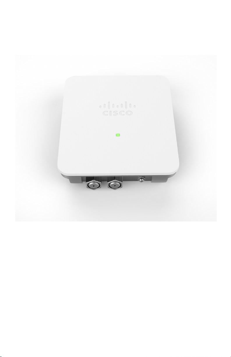
Thank you for choosing the Cisco WAP571E Wireless-AC/N Premium Dual
Radio Outdoor Access Point. The Cisco WAP571E is an outdoor dual radio
802.11ac + 802.11n access point.
This guide is designed to familiarize you with the general layout of the
access point, describe how to deploy the device in your network, and
describe how to configure the device. Your access point has more features
and functionality than what is described in this guide. For additional
information, see the Administration Guide. A link to the Administration
Guide is found in Where to Go From Here.
Package Contents
• Wireless Access Point
• Mounting kit
• This Quick Start Guide
• Ethernet cable
• Pointer Card with China RoHS
• Technical Support Contacts
• EU Directives 1999/5/EC Compliance Information (for EU SKU only)
Before You Begin
Before you begin the installation, make sure that you have the following
equipment and services:
• A computer with browser support for:
– Internet Explorer v7.0 or later
– Chrome v5.0 or later
– Firefox v3.0 or later
–Safari v3.0 or later
• Tools for installing the hardware
• One or more Ethernet network switches with PoE
• Must use only 26 AWG or larger Ethernet cable
1 Cisco WAP571E Wireless Access Point

Cisco WAP571E Wireless-AC/N Premium
2
Dual Radio Outdoor Access Point Features
Front Panel
The front panel of the device consists of a single system LED. For a full
description of the colors of the light and its indications, see Verifying the
Hardware Installation.
Back Panel
The back panel of the device has a water proof RJ-45 Ethernet port and
reset bottom. Facing the side of the device, the right port (labeled
"ETH0/PD") is an 802.3at and 802.3af Power over Ethernet (PoE) port
which is used to power your device. The left port (labeled "ETH1") is a
general Gigabit Ethernet LAN interface. Both are auto-sensing, Gigabit
Ethernet (802.3) ports used to connect your WAP devices to network
devices, such as computers, routers, or switches. We strongly
recommend that you use a Category 5e or better cable for Gigabit
connectivity.
Side Panel
The side panel of the device has a Reset button at right. See Rebooting
the Devices or Returning them to their Factory Default Settings for
information on the Reset button.
Default Setting
Parameter Default Value
Username cisco
Password cisco
LAN IP Address DHCP address assigned
by server
Fallback LAN IP 192.168.1.245
Subnetwork Mask 255.255.255.0
If you are using a Cisco RV Series router, the default range for the DHCP
assigned address is from 192.168.1.100 to 192.168.1.254. Any device
connecting to the same LAN will be assigned an IP address in this range.
If your network does not have an existing DHCP server, the WAP571E will
start a DHCP server for WLAN stations and stop the DHCP client when
WAP571E is in factory default. The DHCP server will assign the IP address
from 192.168.1.20 to 192.168.1.100.
Cisco WAP571E Wireless Access Point 2

Mounting the Cisco WAP571E Wireless-
3
AC/N Premium Dual Radio Outdoor Access
Point
You can place your access point at an outdoor location and mount it on a
wall or pole.
Placement Tips
• Ambient Temperature—To prevent the access point from overheating,
do not operate it in an area that exceeds an ambient temperature of
122°F (55°C).
• Mechanical Loading—The device should be level, stable, and secure
to prevent it from sliding or shifting out of position.
Wall and Pole Mounting
The Cisco WAP571E device can be wall or pole-mounted. A mounting kit is
packaged with your device. The kit is designed to install your device to the
wall or a pole.
The outdoor model includes an adjustable bracket to mount on a flat
vertical surface. Adjustments can be made in up/down, left/right direction
for signal optimization. Pole-mount allows for mounting to small pole (3"
diameter max) and is also adjustable.
3 Cisco WAP571E Wireless Access Point

WARNING Insecure mounting might damage the device or cause injury.
Cisco is not responsible for damages incurred by insecure wall
or pole mounting.
Pole-mounting: To mount the Cisco WAP 571E device on a pole:
STEP 1 Fix Holder_1 and GND wire on WAP571E by 4 M6*10 screws and
screw washers. GND wire can provide better ESD protection.
STEP 2 Fix Holder_2 and Holder_3 on Pole by 4 M6*130 screws and screw
washers.
STEP 3 Fix WAP571E and Holder_1 to Holder_2 by 4 M6*10 Screws and
screw washers.
Cisco WAP571E Wireless Access Point 4
 Loading...