

Page 1

Avaya Definity Gx/PBXLink Integration Guide for Cisco Unity 4.0
Revised March 31, 2006
This document provides instructions for integrating the phone system with Cisco Unity.
Integration Tasks
Before doing the following tasks to integrate Cisco Unity with the Avaya Definity/PBXLink phone
system, confirm that the Cisco Unity server is ready for the integration by completing the applicable
tasks in the applicable Cisco Unity installation guide.
The following task lists describe the process for creating, changing, and deleting integrations.
Task List to Create the Integration
Use the following task list to set up a new integration with the Avaya Definity/PBXLink phone system.
If you are installing a new Cisco Unity server by using th e applicable Cisco Unity installation guide, you
may have already completed some of the following tasks.
1. Review the system and equipment requirements to confirm that all phone system and Cisco Unity
server requirements have been met. See the “Requirements” section on page 2.
2. Plan how the voice messaging ports will be used by Cisco Unity. See the “Planning How the Voice
Messaging Ports Will Be Used by Cisco Unity” section on page 6 .
3. Program the Avaya Definity/PBXLink phone system and extensions. See the “Programming the
Avaya Definity/PBXLink Phone System” section on page 8.
4. Install and configure the PBXLink box. See the “Setting Up the PBXLink Box” section on page 17.
5. Create the integration. See the “Creating a New Integration with the A vaya Def inity/PBXLink Phone
System” section on page 29.
6. Test the integration. See the “Testing the Integration” section on page 33.
7. If you have a secondary server for Cisco Unity failover, integrate the secondary server. See the
“Integrating a Secondary Server for Cisco Unity Failover” section on page 37.
Corporate Headquarters:
Cisco Systems, Inc., 170 West Tasman Drive, San Jose, CA 95134-1706 USA
© 2006 Cisco Systems, Inc. All rights reserved.
Page 2

Requirements
Task List to Make Changes to an Integration
Use the following task list to make changes to an integration after it has been created.
1. Start the Cisco Unity Tele phony Integration M anager (UTIM). Se e the “Changing the Settings for
an Existing Integration” section on page 40.
2. Make the changes you want to the existing integration. See the “Changing the Settings for an
Existing Integration” section on page 40.
Task List to Delete an Existing Integration
Use the following task list to remove an existing integration.
1. Start the Cisco Unity Tele phony Integration M anager (UTIM). Se e the “Deleting an Existing
Integration” section on page 41.
2. Delete the existing integration. See the “Deleting an Existing Integration” section on page 41.
Avaya Definity Gx/PBXLink Integration Guide for CiscoUnity 4.0
Requirements
The Avaya Definity/PBXLink integration supports configurations of the following components:
Phone System
• An Avaya Definity phone system with one or two digital lines connected to the PBX ports on the
• Bridged mode feature, enabled.
• For each voice messaging port, one analog port connected to the voice cards in the Cisco Unity
• The SMDI port in the PBXLink box connected to a serial port (COM1 is the default) on the
PBXLink box. The line or lines must be compatible with the 7434D or 8434D digital phones. If
vectoring will be used and depending on the phone system, the line or lines may require
compatibility with only the 7434D digital phone.
server.
Cisco Unity server with an RS-232 serial ca ble. If multi ple PBXLink box es are in stalled, the SMDI
port of the last PBXLink box is connected to the Management port of the first PBXLink box with
an RS-232 serial cable. The SMDI port of the first PBXLink box is connected to a serial port (COM1
is the default) on the Cisco Unity server with another RS-232 serial cable. Make sure that the serial
protocol parameters for the Management port of the first PBXLink box are set to the same v alues as
the SMDI port.
We recommend that the serial cable have the following construction:
–
A maximum of 50 feet (15.24 m) in length
–
24 AWG stranded conductors
–
Low capacitance—for example, no more than 12 pF/ft (39.4 pF/m) between conductors
–
At least 65 percent braided shield over aluminized polymer sleeve around conductors
–
UL-recognized overall cable jacket insulation with low dielectric constant
–
Braided shield fully terminated to and enclosed by a metal connector backshell
–
Gold-plated connector contacts
Avaya Definity Gx/PBXLink Integration Guide for Cisco Unity4.0
2
OL-3105-15
Page 3

Avaya Definity Gx/PBXLink Integration Guide for Cisco Unity 4.0
• The phone system ready for the integration as described in the installation guide for the phone
system.
Cisco Unity Server
• The applicable voice cards, installed. For details, refer to the “Supported C ircuit-Switched Phone
System Integrations” section in your version of Cisco Unity System Requirements at
http://www.cisco.com/en/US/products/sw/voicesw/ps2237/prod_installation_guides_list.html.
• Cisco Unity installed and ready for the integration, as described in the applicable Cisco Unity
installation guide at
http://www.cisco.com/en/US/products/sw/voicesw/ps2237/prod_installation_guides_list.html.
• A license that enables the applicable number of voice messaging ports.
• An available serial port (COM1 is the default).
Integration Description
The A vaya Def inity/PBXLink integration uses one or more PBXLink boxes, with each box emulating up
to two Avaya 7434D or 8434D digital phones. The PBXLink is connected to the phone system with
digital phone lines and connected to the Cisco Unity server with an RS-232 serial cable. The voice
messaging lines from the phone system connect to the analog voice cards in the Cisco Unity server.
This integration requires that bridged mode be used.
The PBXLink box receives the following call information from the phone system:
Integration Description
• The extension of the called party
• The extension of the calling party (for internal calls) or the phone number of the calling party (if it
is an external call and the system uses caller ID)
• The reason for the forward (the extension is busy, does not answer, or is set to forward all calls)
The PBXLink box formats this information as a Simplified Message Desk Interface (SMDI) packet and
sends the packet to Cisco Unity through the RS-232 serial cable.
Cisco Unity uses this information to answer the call appropriately. For example, a call forwarded to
Cisco Unity is answered with the personal greeting of the subscriber. If the phone system routes the call
to Cisco Unity without this information, Cisco Unity answers with the opening greeting.
Cisco Unity also activates or deactivates messaging waiting indicato rs (MWIs) through the analog voice
messaging ports rather than through the serial data link as in other serial integrations. As a result, it is
necessary to set some voice messaging ports for handling MWIs as described in the “Planning How the
Voice Messaging Ports Will Be Used by Cisco Unity” section on page 6, and to ente r the MWI on and
off codes as described in the “Creating a New Integration with the Avaya Definity/PBXLink Phone
System” section on page 29.
For additional information on the PBXLink box, refer to the PBXLink documentation, which is av ailable
from the manufacturer.
Configuration for 24 or Fewer Ports
A vay a Defi nity/PBXLink inte grations with 2 4 or fe wer ports can use the follo wing conf iguration ( others
are possible):
OL-3105-15
• (Recommended) A single PBXLink-24 box with Port A set for calls only.
Avaya Definity Gx/PBXLink Integration Guide for Cisco Unity 4.0
3
Page 4

Integration Description
Analog lines
P
PBXLink box
er
Avaya Definity Gx/PBXLink Integration Guide for CiscoUnity 4.0
Configuration for 25 to 48 Ports
Avaya Definity/PBXLink integrations with 25 to 48 ports can use one of the following configurations
(others are possible):
• (Recommended) A single PBXLink-48 box with Ports A and B set for calls only.
• Two PBXLink-24 boxes with Port A of both set for calls only.
Configuration for 49 to 72 Ports
Avaya Definity/PBXLink integrations with 49 to 72 ports can use one of the following configurations
(others are possible):
• (Recommended) One PBXLink-24 box with Port A set for calls only, and one PBXLink-48 box with
Ports A and B set for calls only.
• Two PBXLink-48 boxes with Ports A and Port B of both set for calls only.
• Three PBXLink-24 boxes with Port A of all three set for calls only.
PBXLink Box Connections
A single PBXLink box is connected to the phone system with one or two digital phone lines and
connected to the Cisco Unity server with an RS-232 serial cable. The voice messaging lines from the
phone system connect to the analog voice cards in the Cisco Unity server. Figure 1 shows the required
connections.
Figure 1 Serial Connections Between a Single PBXLink Box and Cisco Unity
hone system
Digital lines
RS-232 serial cable
Cisco Unity serv
5419
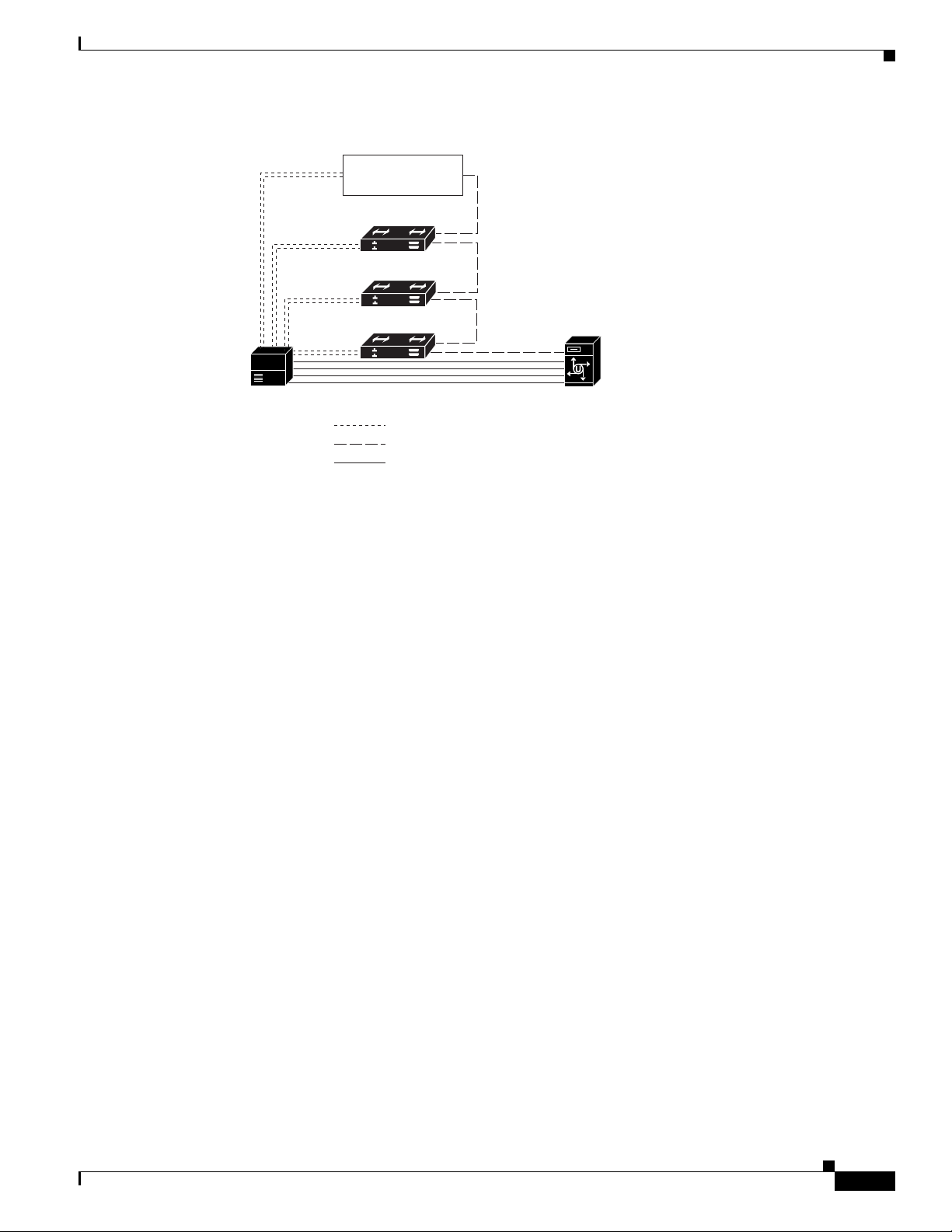
Multiple PBXLink boxes are connected to the Cisco Unity server by using an RS-232 cable to connect
the SMDI port from the last PBXLink box to the Management port of the first PBXLink box. Another
RS-232 cable is then used to connect the SMDI port of the first PBXLink box to the Cisco Unity server.
The voice messaging lines from the phone system connect to the analog voice cards in the Cisco Unity
server. Figure 2 shows the required connections.
Avaya Definity Gx/PBXLink Integration Guide for Cisco Unity 4.0
4
OL-3105-15
Page 5
Avaya Definity Gx/PBXLink Integration Guide for Cisco Unity 4.0
Analog lines
P
er
Figure 2 Serial Connections Between Multiple PBXLink Boxes and Cisco Unity
Add PBXLink
boxes as needed.
PBXLink box #3
PBXLink box #2
PBXLink box #1
hone system Cisco Unity serv
Digital lines
RS-232 serial cables
Integration Description
Integration Functionality
The Avaya Definity/PBXLink integration with Cisco Unity provides the following integration features:
• Call forward to personal greeting
• Call for ward to busy greeting
• Caller ID
• Easy message acc ess (a subscriber can retrieve messages without entering an ID because
Cisco Unity identifies the subscriber based on the extension from which the call originated; a
password may be required)
• Identified subscriber messaging (Cisco Unity identifies the subscriber who lea ves a message during
a forwarded internal call, based on the extension from which the call originated)
• Message waiting indication (MWI)
Integrations with Multiple Phone Systems
Depending on the version, Cisco Unity can be integrated with two or more phone systems:
• Cisco Unity 4.0 and 4.1 can be integrated with a maximum of two phone systems at one time. For
information on and instructions for integrating Cisco Unity with two phone systems, refer to the
Dual Phone System Integration Guide at
http://www.cisco.com/univercd/cc/td/doc/product/voice/c_unity/integuid/multi/itmultin.htm.
• Cisco Unity 4.2 and later can be integrated with two or more phone systems at one time. For
information on the maximum supported combinations and instructions for integrating Cisco Unity
with multiple phone systems, refer to the Multiple Phone System Integration Guide at
http://www.cisco.com/univercd/cc/td/doc/product/voice/c_unity/integuid/multi/multcu42.htm.
OL-3105-15
Avaya Definity Gx/PBXLink Integration Guide for Cisco Unity 4.0
5
Page 6

Avaya Definity Gx/PBXLink Integration Guide for CiscoUnity 4.0
Planning How the Voice Messaging Ports Will Be Used by Cisco Unity
Planning How the Voice Messaging Ports Will Be Used by
Cisco Unity
Before programming the phone system, you ne ed t o pl an how the voice messaging ports will be used b y
Cisco Unity. The following considerations will affect the programming for the phone system (for
example, setting up the hunt group or call forwarding for the voice messaging ports):
• The number of voice messaging ports installed.
• The number of voice messaging ports that will answer calls.
• The number of voice messaging ports that will only dial out, for example, to send message
notification, to set message waiting indicators (MWIs), to make AMIS deliveries, and to make
telephone record and playback (TRAP) connections.
The following table describes the voice messaging port settings in Cisco Unity that can be set in UTIM,
and that are displayed as read-only text on the System > Ports page of the Cisco Unity Administrator.
Table 1 Settings for the Voice Messaging Ports
Field Considerations
Extension Enter the extension for the port as assigned on the phone system.
Enabled Check this check box to enable the port. The port is enabled during normal operation.
Uncheck this check box to disable the port. When the port is disabled, calls to the port get a
ringing tone but are not answered. Typically, the port is disabled only by t he installer during
testing.
Answer Calls Check this check box to designate the port for answering calls. These calls can be incoming
calls from unidentified callers or from subscribers.
Message Notification Check this check box to designate the port for notifying subscribers of messages. Assign
Message Notification to the least busy ports.
Dialout MWI
(not used by serial or SMDI
integrations)
AMIS Delivery
(available with the AMIS
licensed feature only)
TRAP Connection Check this check box so that subscribers can use the phone as a recording and playback
Check this check box to designate t he port for turning MWIs on and of f. Assign Dialout MWI
to the least busy ports.
Check this check box to designate the port for making outbound AMIS calls to deliver voice
messages from Cisco Unity subscribers to users on another voice messaging system.
Cisco Unity supports the Audio Messaging Interchange Specification (AMIS) protocol,
which provides an analog mechanism for transferring voice messages between different
voice messaging systems.
This setting affects outbound AMIS calls only. All ports are used for incoming AMIS calls.
Because the transmission of outgoing AMIS messages may tie up voice ports for long
periods of time, you may want to adjust the schedule on the Network > AMIS > Schedule
page so that outgoing AMIS calls are placed during closed hours or at times when
Cisco Unity is not processing many calls.
device in Cisco Unity web applications and e-mail clients. Assign TRAP Connection to the
least busy ports.
The Number of Voice Messaging Ports to Install
The number of voice messaging ports to install depends on numerous factors, including:
Avaya Definity Gx/PBXLink Integration Guide for Cisco Unity 4.0
6
OL-3105-15
Page 7

Avaya Definity Gx/PBXLink Integration Guide for Cisco Unity 4.0
• The number of calls Cisco Unity will answer when call traffic is at its peak.
• The expected length of each message that callers will record and that subscribers will listen to.
• The number of subscribers.
• The number of ports that will be set to dial out only.
• The number of calls made for message notification.
• The number of MWIs that will be activated when call traffic is at its peak.
• The number of AMIS delivery calls.
• The number of TRAP connections ne eded when call traffic is at its peak. (TRAP connections are
used by Cisco Unity web applications and e-mail clients to play back and record over the phone.)
• The number of calls that will use the automated attendant and call handlers when call traffic is at its
peak.
It is best to install only the number of voice messag ing ports that are need ed so that system resources are
not allocated to unused ports.
The Number of Voice Messaging Ports That Will Answer Calls
The calls that the voice messaging ports answer can be inco ming cal ls from unidenti fied callers or from
subscribers. Typically, the voice messaging ports that answer calls are the busiest.
Planning How the Voice Messaging Ports Will Be Used by Cisco Unity
You can set voice messaging ports to both answer calls and to dial out (for example, to send message
notifications). However, when the voice messaging ports perform more than one function and are very
active (for example, answering man y calls), the other functions may be delayed until the v oice messaging
port is free (for example, message notif icat ions canno t be sent until there are fewer calls to answer). For
best performance, dedicate certain voice messaging ports for only answering incoming calls, and
dedicate other ports for only dialing out. Separating these port functions eliminates the possibility of a
collision, in which an incoming call arrives on a port at the same time that Cisco Unity takes the port
off-hook to dial out.
The Number of Voice Messaging Ports That Will Only Dial Out, and Not Answer Calls
Ports that will only dial out and will not answer calls can do one or more of the following:
• Notify subscribers by phone, pager, or e-mail of messages that have arrived.
• Turn MWIs on and off for subscriber extensions.
• Make outbou nd AMIS cal ls to de liver voice messages from Cisco Unity subscribers to users on
another voice messaging system. (This action is available only with the AMIS licensed feature.)
• Make a TRAP connection so that subscribers can use the phone as a recording and playback device
in Cisco Unity web applications and e-mail clients.
Typically, these voice messaging ports are the least busy ports.
Caution In programming the phone system, do not send calls to v oice messaging ports in Cisco Unity that cannot
answer calls (voice messaging ports that are not set to Answer Calls). For e xample, if a v o ice mess aging
port is set only to Dialout MWI, do not send calls to it.
Preparing for Programming the Phone System
Record your decisions about the voice messaging p orts to guid e you in pro gra mmi ng the ph one sy stem .
OL-3105-15
Avaya Definity Gx/PBXLink Integration Guide for Cisco Unity 4.0
7
Page 8

Avaya Definity Gx/PBXLink Integration Guide for CiscoUnity 4.0
Programming the Avaya Definity/PBXLink Phone System
Programming the Avaya Definity/PBXLink Phone System
If you use programming options other than those supplied in the following procedure, the performance
of the integration may be affected.
Caution In programming the phone system, do not send calls to v oice messaging ports in Cisco Unity that cannot
answer calls (voice messaging ports that are not set to Answer Calls). For e xample, if a v o ice mess aging
port is set only to Message Notification, do not send calls to it.
Make sure that the phone system sends calls only to Cisco Unity voice ports that are set to Answer Calls
on the System > Ports page in the Cisco Unity Administrator. Calls sent to a voice port not set to Answer
Calls can n o t b e a n s w e r e d by C i s c o U n i t y and may cause other problems.
Do the following procedures as applicable.
To Program the Phone System
Step 1 Us e the Add Station <extension number> command (for example, Add Station 2001) to assign an
extension number for each voice messaging port. Set the following options and press Enter.
The options available may vary depending on the software version of your phone system.
Table 2 Voice Messaging Port Options
Option Setting
Extension <the extension number of the voice messaging port>
Type 2500
Port <the physical address of the port>
Lock Messages? n
Test? n
Name VoiceMail 2001
(The extension number must appear within the first 16
characters.)
LWC Reception? n
LW C A ct ivation? y
Redirect Notification? n
Off Premise Station? n
Coverage Msg Retrieval Permission? n
Data Restriction? y
Call Waiting Indication? n
Distinctive Audible Alert? n
Message Waiting Indicator? n
Adjunct Supervision y
Avaya Definity Gx/PBXLink Integration Guide for Cisco Unity 4.0
8
OL-3105-15
Page 9

Avaya Definity Gx/PBXLink Integration Guide for Cisco Unity 4.0
Step 2 Us e the Add Station <extension number> command (for example, Add Station 2999) to assign an
extension number for each digital line to the PBXLink box. Set the digital line options (Table 3) and
button assignments (Table 4).
Table 3 Digital Line Options for All Lines
Option Setting
Extension <the extension number of the d igital l ine>
Type
Port <the physical address of the port>
Data Module? n
Expansion Module? n
LWC Reception None
LW C A ct ivation? y
CDR Privacy? n
Redirect Notification? n
Per Button Ring Control? n
Bridged Call Alerting? n
Active Station Ringing Single
Auto Select Any Idle Appearance? n
Coverage Msg Retrieval? y
Auto Answer None
Data Restriction? n
Idle Appearance Preference? n
Restrict Last Appearance? y
Audible Message Waiting? n
Display Client Redirection? n
Select Last Used Appearance? n
Programming the Avaya Definity/PBXLink Phone System
• 8434D
• 7434D
OL-3105-15
Table 4 Button Assignments for All Lines
Button Assignment Setting
1 call-appr
2 call-appr
3 call-appr
4 normal
(Use the Normal setting for programming a 7434D phone. Leave the
setting blank for an 8434D phone.)
5 inspect
6
Avaya Definity Gx/PBXLink Integration Guide for Cisco Unity 4.0
9
Page 10

Programming the Avaya Definity/PBXLink Phone System
Table 4 Button Assignments for All Lines (continued)
Button Assignment Setting
7
8
9
10 call-appr
Step 3 Set the applicable feature button assignments depending on the number of PBXLink digital ports and
whether load balancing is used.
If there is a single PBXLink digital port and load balancing is not used, set the feature button
assignments as shown in Table 5, then press Enter.
Table 5 Feature Button Assignments for a Single PBXLink Digital Port Without Load
Balancing
Feature Button Number Setting
1 abrdg-appr Extn: <1st voice mail extension>
2 abrdg-appr Extn: <2nd voice mail extension>
3 abrdg-appr Extn: <3rd voice mail extension>
.
.
.
Avaya Definity Gx/PBXLink Integration Guide for CiscoUnity 4.0
<the remaining voice mail extensions>
If there are two PBXLink digital ports and load balancing is used, set the feature button assignments as
shown in both Table 6 and Table 7, then press Enter.
Table 6 Feature Button Assignments for First of Two PBXLink Digital Ports with Load
Balancing
Feature Button Number Setting
1 abrdg-appr Extn: <1st voice mail extension>
2 abrdg-appr Extn: <3rd voice mail extension>
3 abrdg-appr Extn: <5th voice mail extension>
.
<the remaining odd-numbered voice mail extensions>
.
.
Table 7 Feature Button Assignments for Second of Two PBXLink Digital Ports with Load
Balancing
Feature Button Number Setting
1 abrdg-appr Extn: <2nd voice mail extension>
2 abrdg-appr Extn: <4th voice mail extension>
10
Avaya Definity Gx/PBXLink Integration Guide for Cisco Unity 4.0
OL-3105-15
Page 11

Avaya Definity Gx/PBXLink Integration Guide for Cisco Unity 4.0
Table 7 Feature Button Assignments for Second of Two PBXLink Digital Ports with Load
Balancing (continued)
Feature Button Number Setting
3 abrdg-appr Extn: <6th voice mail extension>
.
.
.
If there are three PBXLink digital ports and load balancing is used, set the feature button assignments
as shown in Table 8, Table 9, and Table 10, then press Enter.
Table 8 Feature Button Assignments for First of Three PBXLink Digital Ports with Load
Balancing
Feature Button Number Setting
1 abrdg-appr Extn: <1st voice mail extension>
2 abrdg-appr Extn: <4th voice mail extension>
3 abrdg-appr Extn: <7th voice mail extension>
.
.
.
Programming the Avaya Definity/PBXLink Phone System
<the remaining even-numbered voice mail extensions>
<every third remaining voice mail extension>
Table 9 Feature Button Assignments for Second of Three PBXLink Digital Ports with Load
Balancing
Feature Button Number Setting
1 abrdg-appr Extn: <2nd voice mail extension>
2 abrdg-appr Extn: <5th voice mail extension>
3 abrdg-appr Extn: <8th voice mail extension>
.
<every third remaining voice mail extension>
.
.
OL-3105-15
Avaya Definity Gx/PBXLink Integration Guide for Cisco Unity 4.0
11
Page 12

Programming the Avaya Definity/PBXLink Phone System
Table 10 Feature Button Assignments for Third of Three PBXLink Digital Ports with Load
Balancing
Feature Button Number Setting
1 abrdg-appr Extn: <3rd voice mail extension>
2 abrdg-appr Extn: <6th voice mail extension>
3 abrdg-appr Extn: <9th voice mail extension>
.
.
.
If the phone system has 1 to 8 voice messaging ports or if it does not have vectoring capability, do the
procedure “To Set Up Coverage Paths for One to Eight Voice Messaging Ports or for Phone Systems
Without Vectoring Capability.” Otherwise, do the procedure “To Set up Coverage Paths for More Than
Eight Voice M essaging Ports .”
Avaya Definity Gx/PBXLink Integration Guide for CiscoUnity 4.0
<every third remaining voice mail extension>
To Set Up Coverage Paths for One to Eight Voice Messaging Ports or for Phone Systems Without Vectoring
Capability
Step 1 Refer to Chapter 6 in the PBXLink documentation, which is available from the manufacturer.
To Set up Coverage Paths for More Than Eight Voice Messaging Ports
Step 1 For a phone system with more than eight voice messaging ports, use th e Add Vdn <extension number>
command (for example Add Vdn 2000) to set up a vector directory number for the pilot number
(extension 2000 in this example). Set the following options and press Enter.
Table 11 Vector Direction Number Options
Option Setting
Extension <the pilot number>
Name VoiceMail 2000
Display Override? n
COR 1
Ve ctor Number 1
(must match the Number option in Table 12)
Measured none
12
Step 2 Us e the Add Vector 1 or the Change Vector 1 command to define the vector for voice messaging port
extensions that answer calls. Set the options according to one of the following examples. Then press
Enter.
For a system with a single PBXLink digital port, use the following example of a system with six lines.
Avaya Definity Gx/PBXLink Integration Guide for Cisco Unity 4.0
OL-3105-15
Page 13

Avaya Definity Gx/PBXLink Integration Guide for Cisco Unity 4.0
Table 12 Vector Definition Options for a Single Digital Port
Option Setting
Number 1
(must match the Vector Number option in Table 11)
Name voicevec
ASAI Routing? n
Basic? y
Prompting? n
01 wait time 0 secs hearing ringback
02 route to number 2001 if unconditionally
(use the first voice messaging port extension)
03 route to number 2002 if unconditionally
04 route to number 2003 if unconditionally
05 route to number 2004 if unconditionally
06 route to number 2005 if unconditionally
07 route to number 2006 if unconditionally
08 busy
Programming the Avaya Definity/PBXLink Phone System
For a system with two PBXLink digital ports, use the following example, which bridges every second
extension to Port A and the remaining extensions to Port B.
Table 13 Vector Definition Options for Call Vector 1
Option Setting
Number 1
Name voicevec1
ASAI Routing? n
Basic? y
Prompting? n
01 wait time 0 secs hearing ringback
02 route to number 2001 if unconditionally
03 route to number 2002 if unconditionally
04 route to number 2003 if unconditionally
05 route to number 2004 if unconditionally
06 route to number 2005 if unconditionally
07 route to number 2006 if unconditionally
08 route to number 2007 if unconditionally
09 route to number 2008 if unconditionally
10 route to number 2009 if unconditionally
OL-3105-15
Avaya Definity Gx/PBXLink Integration Guide for Cisco Unity 4.0
13
Page 14

Programming the Avaya Definity/PBXLink Phone System
Table 13 Vector Definition Options for Call Vector 1 (continued)
Option Setting
11 route to number 2010 if unconditionally
12 goto vector 2 if unconditionally
Table 14 Vector Definition Options for Call Vector 2
Option Setting
Number 2
Name voicevec2
ASAI Routing? n
Basic? y
Prompting? n
01 route to number 2011 if unconditionally
02 route to number 2012 if unconditionally
03 route to number 2013 if unconditionally
04 route to number 2014 if unconditionally
05 route to number 2015 if unconditionally
06 route to number 2016 if unconditionally
07 route to number 2017 if unconditionally
08 route to number 2018 if unconditionally
09 route to number 2019 if unconditionally
10 route to number 2020 if unconditionally
11 busy
Avaya Definity Gx/PBXLink Integration Guide for CiscoUnity 4.0
14
For a system with three PBXLink digital ports, use the following example, which bridges every third
extension to Port A, another third of the extensions to Port B, and the remaining extensions to Port C.
Table 15 Vector Definition Options for Call Vector 1
Option Setting
Number 1
Name voicevec1
ASAI Routing? n
Basic? y
Prompting? n
01 wait time 0 secs hearing ringback
02 route to number 2001 if unconditionally
03 route to number 2002 if unconditionally
04 route to number 2003 if unconditionally
Avaya Definity Gx/PBXLink Integration Guide for Cisco Unity 4.0
OL-3105-15
Page 15

Avaya Definity Gx/PBXLink Integration Guide for Cisco Unity 4.0
Table 15 Vector Definition Options for Call Vector 1 (continued)
Option Setting
05 route to number 2004 if unconditionally
06 route to number 2005 if unconditionally
07 route to number 2006 if unconditionally
08 route to number 2007 if unconditionally
09 route to number 2008 if unconditionally
10 route to number 2009 if unconditionally
11 route to number 2010 if unconditionally
12 goto vector 2 if unconditionally
Table 16 Vector Definition Options for Call Vector 2
Option Setting
Number 2
Name voicevec2
ASAI Routing? n
Basic? y
Prompting? n
01 route to number 2011 if unconditionally
02 route to number 2012 if unconditionally
03 route to number 2013 if unconditionally
04 route to number 2014 if unconditionally
05 route to number 2015 if unconditionally
06 route to number 2016 if unconditionally
07 route to number 2017 if unconditionally
08 route to number 2018 if unconditionally
09 route to number 2019 if unconditionally
10 route to number 2020 if unconditionally
11 goto vector 3 if unconditionally
Programming the Avaya Definity/PBXLink Phone System
OL-3105-15
Avaya Definity Gx/PBXLink Integration Guide for Cisco Unity 4.0
15
Page 16

Programming the Avaya Definity/PBXLink Phone System
Table 17 Vector Definition Options for Call Vector 3
Option Setting
Number 3
Name voicevec3
ASAI Routing? n
Basic? y
Prompting? n
01 route to number 2021 if unconditionally
02 route to number 2022 if unconditionally
03 route to number 2023 if unconditionally
04 route to number 2024 if unconditionally
05 route to number 2025 if unconditionally
06 route to number 2026 if unconditionally
07 route to number 2027 if unconditionally
08 route to number 2028 if unconditionally
09 route to number 2029 if unconditionally
10 route to number 2030 if unconditionally
11 busy
Avaya Definity Gx/PBXLink Integration Guide for CiscoUnity 4.0
After programming the phone system, it is necessary to set up the direct lines for users on the phone
system.
To Set Up User Phones
Step 1 Use the Change Station (extension number) command to display the Station screen fo r each extensio n.
Step 2 In the Name field, enter the user’s name and extension. The PBXLink box can display only the first 16
characters, and the extension must appear in these 16 characters.
Step 3 In the Coverage Path field, enter 1.
Note You can use alternate extensions to create multiple line appearances, enable easy message access from
cell phones, and simplify addressing messages to subscribers at different locations in Cisco Unity.
Enabling alternate MWIs lets Cisco Unity turn MWIs on at more than one extension. For details, see the
“Appendix: Using Alternate Extensions and MWIs” section on page 41.
16
Avaya Definity Gx/PBXLink Integration Guide for Cisco Unity 4.0
OL-3105-15
Page 17

Avaya Definity Gx/PBXLink Integration Guide for Cisco Unity 4.0
Setting Up the PBXLink Box
When setting up the PBXLink box, you can access the configuration menus through the display panel
and buttons on the PBXLink box. For details, refer to the PBXLink documentation, which is available
from the manufacturer.
To Update the PBXLink Box Firmware
Step 1 In a web browser on your computer, go to the Cisco Unity Utilities Software Download page at
http://www.cisco.com/cgi-bin/tablebuild.pl/unity-util.
Note To access the software download page, you must be logged on to Cisco.com as a registered user.
Step 2 Click P BXLinkFirmwareUpdate.
Step 3 Follow the instructions to download the PBXLink box firmware update file to your computer.
Step 4 Ex it the web br owser.
Setting Up the PBXLink Box
Step 5 Confirm that the PBXLink box is connected to power and turned on.
Step 6 Disc onnect the following cables:
• All phone cables connect to the PBXLink box.
• The RS-232 serial cable connected to the Management port
Step 7 Connect one end of am RS-232 serial cable to the Management port of the PBXLink box and the other
end of the serial cable to the serial port of your computer.
Step 8 On your computer, start HyperTerminal or another terminal access application.
Step 9 Set the termina l access application to use the serial connection settings used by the PBXLink box. You
can view the PBXLink serial connection settings by doing the following:
a. On the PBXLink box, press Cancel until the Configuration menu appears.
b. Click OK.
c. Scroll up until Serial Port Options appears, and click OK.
d. Scroll down until Management Port appears, and click OK.
e. Scroll through the serial port settings to verify them.
Step 10 Restart the PBXLink box.
Step 11 In the HyperTerminal window on your computer, press M and press Enter.
Step 12 Press 3 (Reboot/Download), and press Enter.
Step 13 Press 2 (Reboot & Download Code), and press Enter.
OL-3105-15
Note Ignore any unusual characters that may appear on the screen.
Step 14 On the Transfer menu, click Send File.
Step 15 In the Send File dialog box, under Filename, click Browse.
Step 16 Browse to the PBXLink box firmware upgrade file that you downloaded to your computer.
Step 17 In the Send File dialog box, under Protocol, click Xmodem.
Avaya Definity Gx/PBXLink Integration Guide for Cisco Unity 4.0
17
Page 18

Setting Up the PBXLink Box
Step 18 Click Send.
Step 19 When the firmware upgrade is complete, exit HyperTerminal.
Step 20 Repeat Step 5 through Step 19 for all remaining PBXLink boxes.
Step 21 Connect the PBXLink boxes to the phone system and to the Cisco Unity server.
To Set Up the PBXLink Box
Step 1 On the PBXLink box, press Cancel until the main menu appears (the PBXLink version appears in the
display).
Step 2 On the main menu, press the Up or Down arrow to select Configuration and press OK.
Step 3 On the Configuration menu, press the Up or Down arrow to select Integration.
Step 4 Confirm that the Integration option is set to Stopped.
If the Integration option is set to Started, press OK, press the Right or Left arrow to select Stopped, and
press OK.
Step 5 On the Configuration menu, press the Up or Down arrow to select PBX Type and press OK.
Avaya Definity Gx/PBXLink Integration Guide for CiscoUnity 4.0
Step 6 On the PBX Type menu, press OK.
Step 7 On the Select PBX Type menu, press the Right or Left arrow to select either Lucent 2 wire or
Lucent 4 wire and press OK.
If the setting that you select is not the same as the setting that first appeared, the PBXLink box restarts.
Step 8 If the PBXLink box does not restart, on the PBX Type menu, click Cancel.
If the PBXLink box restarts, on the main menu, press the Up or Down arrow to select Configuration
and press OK.
Step 9 On the Configuration menu, press the Up or Down arrow to select PBX Options and press OK.
Step 10 On the PBX Options menu, press the Up or Down arrow to select Phone Set and press OK.
Step 11 On the Phone Set menu, press the Right or Left arrow to select either 8434D or 7434D to match the
digital port setting that you entered with the Add Station command. Then press OK.
Step 12 On the PBX Options menu, press the Up or Down arrow to select Voice Coding and press OK.
Step 13 On the Voice Coding menu, press the Right or Left arrow to select one of the following options and press
OK:
• North America— Mu Law
• All oth er loca tions—A Law
Step 14 On the PBX Options menu, press the Up or Down arrow to select Analog Ports on A and press OK.
Step 15 In the Analog Ports on A field, enter the number of voice messaging ports that Port A will monitor and
press OK.
18
Step 16 If you setting up a PBXLink-24 box, continue to Step 17.
If you are setting up a PBXLink-48 box, do the following substeps:
a. On the PBX Options menu, press the Up or Down arro w to select Anal og Port s on B, and press OK.
b. In the Analog Ports on B field, enter the number of voice messaging ports that Port B will monitor
and press OK.
Avaya Definity Gx/PBXLink Integration Guide for Cisco Unity 4.0
OL-3105-15
Page 19

Avaya Definity Gx/PBXLink Integration Guide for Cisco Unity 4.0
Step 17 On the PBX Options menu, press the Up or Down arrow to select Configure Port A and press OK.
Step 18 On the Configure Port A menu, press the Left or Righ t arrow to select Calls Only and press OK.
Step 19 If you are setting up a PBXLink-24 box, continue to Step 20.
If you are setting up a PBXLink-48 box, do the following substeps:
a. On the PBX Options menu, press the Up or Down arrow to select Configure Port B and press OK.
b. On the Configure Port B menu, press the Right or Left arrow to select Calls Only and press OK.
Step 20 On the PBX Options menu, press the Up or Down arrow to select Prime Number and press OK.
Step 21 In the Prime Number field, enter the pilot number that the phone system uses to call Cisco Unity, and
press OK.
Step 22 On the PBX Options menu, press the Up or Down arrow to select Extension Length and press OK.
Step 23 In the Extension Length field, enter the number of digits in the subscriber extensions and press OK. If
the subscriber extensions have different lengths, enter the number of digits in the longest extension.
Step 24 On the PBX Options menu, press Cancel.
Step 25 On the Configuration menu, press the Up or Down arrow to select Integration and press OK.
Step 26 On the Integration menu, press the Right or Left arrow to select Started and press OK.
Setting Up the PBXLink Box
If the system has two or more PBXLink digital ports, we recommend that you balance the load among
the PBXLink boxes by setting up the Port LTNs for random operation. Depending on the number of
PBXLink digital ports and the number of PBXLink boxes that your system uses, do the applicable
procedure that follows.
To Set Up the Port LTNs for Two PBXLink Digital Ports on One PBXLink Box
Step 1 Confirm that the PBXLink Integration option is set to Stopped by doing the following substeps:
a. On the main menu, press the Up or Down arrow to select Configuration and press OK.
b. On the Configuration menu, press the Up or Down arrow to select Integration.
c. Confirm that the Integration option is set to Stopped.
If the Integration option is set to S tarted, press OK, press th e Right or Left arro w to select Stopped,
and press OK.
Step 2 On the Configuration menu, press the Up or Down arrow to select SMDI Options and press OK.
Step 3 On the SMDI Options menu, press the Up or Down arrow to select Port A LTNs, and press OK.
Step 4 On the Port A LTNs menu, press the Up or Down arrow to select Mode of Operation and press OK.
Step 5 On the Mode of Operation menu, press the Right or Left arrow to select Random and press OK.
Step 6 On the Port A LTNs menu, press the Up or Down arrow to select Setup Random LTNs and press OK.
Step 7 In the Setup Random LTNs field, enter the voice messaging port values (not the extension) for each
odd-numbered voice messaging port as shown in the following table, and press OK.
OL-3105-15
Avaya Definity Gx/PBXLink Integration Guide for Cisco Unity 4.0
19
Page 20

Setting Up the PBXLink Box
Table 18 Random LTN Settings for Odd-Numbered Ports
LTN Number Voice Messaging Port Value
00001
10003
20005
.
.
.
Step 8 After all the odd-numbered voice messaging ports are set, press Cancel.
Step 9 On the Port A LTNs menu, press Cancel.
Step 10 On the SMDI Options menu, press the Up or Down arrow to select Port B LTNs and press OK.
Step 11 On the Port B LTNs menu, press the Up or Down arrow to select Mode of Operation and press OK.
Step 12 On the Mode of Operation menu, press the Right or Left arrow to select Random and press OK.
Step 13 On the Port B LTNs menu, press the Up or Down arrow to select Setup Random LTNs and press OK.
Step 14 In the Setup Random LTNs field, enter the voice messaging port values (not the extension) for each
even-numbered voice messaging port as shown in the following table, and press OK.
Avaya Definity Gx/PBXLink Integration Guide for CiscoUnity 4.0
<the remaining odd-numbered voice messaging ports>
Table 19 Random LTN Settings for Even-Numbered Ports
LTN Number Voice Messaging Port Value
00002
10004
20006
.
<the remaining even-numbered voice messaging ports>
.
.
Step 15 After all the even-numbered voice messaging ports are set, press Cancel.
Step 16 On the Port B LTNs menu, press Cancel.
Step 17 On the SMDI Options menu, press Cancel.
Step 18 On the Configuration menu, press the Up or Down arrow to select Integration and press OK.
Step 19 On the Integration menu, press the Right or Left arrow to select Started, and press OK.
Step 20 Continue to the “Creating a New Integration with the Avaya Definity/PBXLink Phone System” section
on page 29.
20
Avaya Definity Gx/PBXLink Integration Guide for Cisco Unity 4.0
OL-3105-15
Page 21

Avaya Definity Gx/PBXLink Integration Guide for Cisco Unity 4.0
To Set Up the Port LTNs for Two PBXLink Digital Ports on Two PBXLink Boxes
Step 1 On the first PBXLink box, confirm that the PBXLink Integration option is set to Stopped by doing the
following substeps:
a. On the main menu, press the Up or Down arrow to select Configuration and press OK.
b. On the Configuration menu, press the Up or Down arrow to select Integration.
c. Confirm that the Integration option is set to Stopped.
If the Integration option is set to S tarted, press OK, press th e Right or Left arro w to select Stopped,
and press OK.
Step 2 On the Configuration menu, press the Up or Down arrow to select SMDI Options and press OK.
Step 3 On the SMDI Options menu, press the Up or Down arrow to select Port A LTNs, and press OK.
Step 4 On the Port A LTNs menu, press the Up or Down arrow to select Mode of Operation and press OK.
Step 5 On the Mode of Operation menu, press the Right or Left arrow to select Random and press OK.
Step 6 On the Port A LTNs menu, press the Up or Down arrow to select Setup Random LTNs and press OK.
Step 7 In the Setup Random LTNs field, enter the voice messaging port values (not the extension) for each
odd-numbered voice messaging port as shown in the following table, and press OK.
Setting Up the PBXLink Box
Table 20 Random LTN Settings for Odd-Numbered Ports
LTN Number Voice Messaging Port Value
00001
10003
20005
.
<the remaining odd-numbered voice messaging ports>
.
.
Step 8 After all the odd-numbered voice messaging ports are set, press Cancel.
Step 9 On the Port A LTNs menu, press Cancel.
Step 10 On the SMDI Options menu, press Cancel.
Step 11 On the Configuration menu, press the Up or Down arrow to select Integration and press OK.
Step 12 On the Integration menu, press the Right or Left arrow to select Started, and press OK.
Step 13 On the second PBXLink box, confirm that the PBXLink Integration option is set to Stopped by doing
the following substeps:
a. On the main menu, press the Up or Down arrow to select Configuration and press OK.
b. On the Configuration menu, press the Up or Down arrow to select Integration.
OL-3105-15
c. Confirm that the Integration option is set to Stopped.
If the Integration option is set to S tarted, press OK, press th e Right or Left arro w to select Stopped,
and press OK.
Step 14 On the Configuration menu, press the Up or Down arrow to select SMDI Options and press OK.
Step 15 On the SMDI Options menu, press the Up or Down arrow to select Port A LTNs, and press OK.
Avaya Definity Gx/PBXLink Integration Guide for Cisco Unity 4.0
21
Page 22

Setting Up the PBXLink Box
Step 16 On the Port A LTNs menu, press the Up or Down arrow to select Mode of Operation and press OK.
Step 17 On the Mode of Operation menu, press the Right or Left arrow to select Random and press OK.
Step 18 On the Port A LTNs menu, press the Up or Down arrow to select Setup Random LTNs and press OK.
Step 19 In the Setup Random LTNs field, enter the voice messaging port values (not the extension) for each
even-numbered voice messaging port as shown in the following table, and press OK.
Table 21 Random LTN Settings for Even-Numbered Ports
LTN Number Voice Messaging Port Value
00002
10004
20006
.
.
.
Step 20 After all the even-numbered voice messaging ports are set, press Cancel.
Step 21 On the Port A LTNs menu, press Cancel.
Step 22 On the SMDI Options menu, press Cancel.
Avaya Definity Gx/PBXLink Integration Guide for CiscoUnity 4.0
<the remaining even-numbered voice messaging ports>
Step 23 On the Configuration menu, press the Up or Down arrow to select Integration and press OK.
Step 24 On the Integration menu, press the Right or Left arrow to select Started, and press OK.
Step 25 Continue to the “Creating a New Integration with the Avaya Definity/PBXLink Phone System” section
on page 29.
To Set Up the Port LTNs for Three PBXLink Digital Ports (One PBXLink Box with One Digital Port and One PBXLink
Box with Two Digital Ports)
This procedure sets up the port LTNs for every third voice messaging port when the first PBXLink box
uses only Port A, and the second PBXLink box uses Port A and Port B.
Step 1 On the first PBXLink box (which has one digital port), confirm that the PBXLink Integration option is
set to Stopped by doing the following substeps:
a. On the main menu, press the Up or Down arrow to select Configuration and press OK.
b. On the Configuration menu, press the Up or Down arrow to select Integration.
c. Confirm that the Integration option is set to Stopped.
If the Integration option is set to S tarted, press OK, press th e Right or Left arro w to select Stopped,
and press OK.
Step 2 On the Configuration menu, press the Up or Down arrow to select SMDI Options and press OK.
Step 3 On the SMDI Options menu, press the Up or Down arrow to select Port A LTNs, and press OK.
Step 4 On the Port A LTNs menu, press the Up or Down arrow to select Mode of Operation and press OK.
22
Step 5 On the Mode of Operation menu, press the Right or Left arrow to select Random and press OK.
Step 6 On the Port A LTNs menu, press the Up or Down arrow to select Setup Random LTNs and press OK.
Avaya Definity Gx/PBXLink Integration Guide for Cisco Unity 4.0
OL-3105-15
Page 23

Avaya Definity Gx/PBXLink Integration Guide for Cisco Unity 4.0
Step 7 In the Setup Random LTNs field, enter the voice messaging port values (not the extension) for the first
set of voice messaging port as shown in the following table, and press OK.
Table 22 Random LTN Settings for the First Set of Ports
LTN Number Voice Messaging Port Value
00001
10004
20007
.
.
.
Step 8 After all of the voice messaging ports in the first set are set, press Cancel.
Step 9 On the Port A LTNs menu, press Cancel.
Step 10 On the SMDI Options menu, press Cancel.
Step 11 On the Configuration menu, press the Up or Down arrow to select Integration and press OK.
Step 12 On the Integration menu, press the Right or Left arrow to select Started, and press OK.
Step 13 On the second PBXLink box (which has two digital ports), conf irm that the PBXLink Inte gration option
is set to Stopped by doing the following substeps:
Setting Up the PBXLink Box
<the remaining voice messaging ports in the first set>
a. On the main menu, press the Up or Down arrow to select Configuration and press OK.
b. On the Configuration menu, press the Up or Down arrow to select Integration.
c. Confirm that the Integration option is set to Stopped.
If the Integration option is set to S tarted, press OK, press th e Right or Left arro w to select Stopped,
and press OK.
Step 14 On the Configuration menu, press the Up or Down arrow to select SMDI Options and press OK.
Step 15 On the SMDI Options menu, press the Up or Down arrow to select Port A LTNs, and press OK.
Step 16 On the Port A LTNs menu, press the Up or Down arrow to select Mode of Operation and press OK.
Step 17 On the Mode of Operation menu, press the Right or Left arrow to select Random and press OK.
Step 18 On the Port A LTNs menu, press the Up or Down arrow to select Setup Random LTNs and press OK.
Step 19 In the Setup Random L TNs f ield, enter the voice messaging port v alues (not the extension) for the second
set of voice messaging port as shown in the following table, and press OK.
Table 23 Random LTN Settings for the Second Set of Ports
LTN Number Voice Messaging Port Value
00002
10005
20008
.
<the remaining voice messaging ports in the second set>
.
.
OL-3105-15
Avaya Definity Gx/PBXLink Integration Guide for Cisco Unity 4.0
23
Page 24

Setting Up the PBXLink Box
Step 20 After all of the voice messaging ports in the second set are set, press Cancel.
Step 21 On the Port A LTNs menu, press Cancel.
Step 22 On the SMDI Options menu, press the Up or Down arrow to select Port B LTNs and press OK.
Step 23 On the Port B LTNs menu, press the Up or Down arrow to select Mode of Operation and press OK.
Step 24 On the Mode of Operation menu, press the Right or Left arrow to select Random and press OK.
Step 25 On the Port B LTNs menu, press the Up or Down arrow to select Setup Random LTNs and press OK.
Step 26 In the Setup Random LTNs field, enter the voice messaging port values (not the extension) for the third
set of voice messaging port as shown in the following table, and press OK.
Table 24 Random LTN Settings for the Third Set of Ports
LTN Number Voice Messaging Port Value
00003
10006
20009
.
.
.
Avaya Definity Gx/PBXLink Integration Guide for CiscoUnity 4.0
<the remaining voice messaging ports in the third set>
Step 27 After all of the voice messaging ports in the third set are set, press Cancel.
Step 28 On the Port B LTNs menu, press Cancel.
Step 29 On the SMDI Options menu, press Cancel.
Step 30 On the Configuration menu, press the Up or Down arrow to select Integration and press OK.
Step 31 On the Integration menu, press the Right or Left arrow to select Started, and press OK.
Step 32 Continue to the “Creating a New Integration with the Avaya Definity/PBXLink Phone System” section
on page 29.
To Set Up the Port LTNs for Three PBXLink Digital Ports (One PBXLink Box with Two Digital Ports and One PBXLink
Box with One Digital Port)
This procedure sets up the port LTNs for every third voice messaging port when the first PBXLink box
uses Port A and Port B, and the second PBXLink box uses only Port A.
Step 1 On the first PBXLink box (which has two digital ports), confirm t hat the PBXLin k Integration option is
set to Stopped by doing the following substeps:
a. On the main menu, press the Up or Down arrow to select Configuration and press OK.
b. On the Configuration menu, press the Up or Down arrow to select Integration.
c. Confirm that the Integration option is set to Stopped.
If the Integration option is set to S tarted, press OK, press th e Right or Left arro w to select Stopped,
and press OK.
24
Step 2 On the Configuration menu, press the Up or Down arrow to select SMDI Options and press OK.
Step 3 On the SMDI Options menu, press the Up or Down arrow to select Port A LTNs, and press OK.
Avaya Definity Gx/PBXLink Integration Guide for Cisco Unity 4.0
OL-3105-15
Page 25

Avaya Definity Gx/PBXLink Integration Guide for Cisco Unity 4.0
Step 4 On the Port A LTNs menu, press the Up or Down arrow to select Mode of Operation and press OK.
Step 5 On the Mode of Operation menu, press the Right or Left arrow to select Random and press OK.
Step 6 On the Port A LTNs menu, press the Up or Down arrow to select Setup Random LTNs and press OK.
Step 7 In the Setup Random LTNs field, enter the voice messaging port values (not the extension) for the first
set of voice messaging port as shown in the following table, and press OK.
Table 25 Random LTN Settings for the First Set of Ports
LTN Number Voice Messaging Port Value
00001
10004
20007
.
.
.
Step 8 After all of the voice messaging ports in the first set are set, press Cancel.
Step 9 On the Port A LTNs menu, press Cancel.
Step 10 On the SMDI Options menu, press the Up or Down arrow to select Port B LTNs and press OK.
Setting Up the PBXLink Box
<the remaining voice messaging ports in the first set>
Step 11 On the Port B LTNs menu, press the Up or Down arrow to select Mode of Operation and press OK.
Step 12 On the Mode of Operation menu, press the Right or Left arrow to select Random and press OK.
Step 13 On the Port B LTNs menu, press the Up or Down arrow to select Setup Random LTNs and press OK.
Step 14 In the Setup Random L TNs f ield, enter the voice messaging port v alues (not the extension) for the second
set of voice messaging port as shown in the following table, and press OK.
Table 26 Random LTN Settings for the Second Set of Ports
LTN Number Voice Messaging Port Value
00002
10005
20008
.
<the remaining voice messaging ports in the second set>
.
.
Step 15 After all of the voice messaging ports in the second set are set, press Cancel.
Step 16 On the Port B LTNs menu, press Cancel.
Step 17 On the SMDI Options menu, press Cancel.
Step 18 On the Configuration menu, press the Up or Down arrow to select Integration and press OK.
Step 19 On the Integration menu, press the Right or Left arrow to select Started, and press OK.
Step 20 On the second PBXLink box (which has one digital port), confirm that the PBXLink Integration option
is set to Stopped by doing the following substeps:
OL-3105-15
a. On the main menu, press the Up or Down arrow to select Configuration and press OK.
Avaya Definity Gx/PBXLink Integration Guide for Cisco Unity 4.0
25
Page 26

Setting Up the PBXLink Box
b. On the Configuration menu, press the Up or Down arrow to select Integration.
c. Confirm that the Integration option is set to Stopped.
Step 21 On the Configuration menu, press the Up or Down arrow to select SMDI Options and press OK.
Step 22 On the SMDI Options menu, press the Up or Down arrow to select Port A LTNs, and press OK.
Step 23 On the Port A LTNs menu, press the Up or Down arrow to select Mode of Operation and press OK.
Step 24 On the Mode of Operation menu, press the Right or Left arrow to select Random and press OK.
Step 25 On the Port A LTNs menu, press the Up or Down arrow to select Setup Random LTNs and press OK.
Step 26 In the Setup Random LTNs field, enter the voice messaging port values (not the extension) for the third
set of voice messaging port as shown in the following table, and press OK.
Table 27 Random LTN Settings for the Third Set of Ports
LTN Number Voice Messaging Port Value
00003
10006
20009
.
.
.
Avaya Definity Gx/PBXLink Integration Guide for CiscoUnity 4.0
If the Integration option is set to S tarted, press OK, press th e Right or Left arro w to select Stopped,
and press OK.
<the remaining voice messaging ports in the third set>
Step 27 After all of the voice messaging ports in the third set are set, press Cancel.
Step 28 On the Port A LTNs menu, press Cancel.
Step 29 On the SMDI Options menu, press Cancel.
Step 30 On the Configuration menu, press the Up or Down arrow to select Integration and press OK.
Step 31 On the Integration menu, press the Right or Left arrow to select Started, and press OK.
Step 32 Continue to the “Creating a New Integration with the Avaya Definity/PBXLink Phone System” section
on page 29.
To Set Up the Port LTNs for Three PBXLink Digital Ports (Three PBXLink Boxes with One Digital Port Each)
This procedure sets up the port LTNs for every third voice messaging port when each of the PBXLink
boxes uses only Port A.
Step 1 On the first PBXLink box (which has one digital port), confirm that the PBXLink Integration option is
set to Stopped by doing the following substeps:
a. On the main menu, press the Up or Down arrow to select Configuration and press OK.
b. On the Configuration menu, press the Up or Down arrow to select Integration.
c. Confirm that the Integration option is set to Stopped.
If the Integration option is set to S tarted, press OK, press th e Right or Left arro w to select Stopped,
and press OK.
26
Avaya Definity Gx/PBXLink Integration Guide for Cisco Unity 4.0
OL-3105-15
Page 27

Avaya Definity Gx/PBXLink Integration Guide for Cisco Unity 4.0
Step 2 On the Configuration menu, press the Up or Down arrow to select SMDI Options and press OK.
Step 3 On the SMDI Options menu, press the Up or Down arrow to select Port A LTNs, and press OK.
Step 4 On the Port A LTNs menu, press the Up or Down arrow to select Mode of Operation and press OK.
Step 5 On the Mode of Operation menu, press the Right or Left arrow to select Random and press OK.
Step 6 On the Port A LTNs menu, press the Up or Down arrow to select Setup Random LTNs and press OK.
Step 7 In the Setup Random LTNs field, enter the voice messaging port values (not the extension) for the first
set of voice messaging port as shown in the following table, and press OK.
Table 28 Random LTN Settings for the First Set of Ports
LTN Number Voice Messaging Port Value
00001
10004
20007
.
.
.
Setting Up the PBXLink Box
<the remaining voice messaging ports in the first set>
Step 8 After all of the voice messaging ports in the first set are set, press Cancel.
Step 9 On the Port A LTNs menu, press Cancel.
Step 10 On the SMDI Options menu, press Cancel.
Step 11 On the Configuration menu, press the Up or Down arrow to select Integration and press OK.
Step 12 On the Integration menu, press the Right or Left arrow to select Started, and press OK.
Step 13 On the second PBXLink box (which has one digital port), confirm that the PBXLink Integration option
is set to Stopped by doing the following substeps:
a. On the main menu, press the Up or Down arrow to select Configuration and press OK.
b. On the Configuration menu, press the Up or Down arrow to select Integration.
c. Confirm that the Integration option is set to Stopped.
If the Integration option is set to S tarted, press OK, press th e Right or Left arro w to select Stopped,
and press OK.
Step 14 On the Configuration menu, press the Up or Down arrow to select SMDI Options and press OK.
Step 15 On the SMDI Options menu, press the Up or Down arrow to select Port A LTNs, and press OK.
Step 16 On the Port A LTNs menu, press the Up or Down arrow to select Mode of Operation and press OK.
Step 17 On the Mode of Operation menu, press the Right or Left arrow to select Random and press OK.
Step 18 On the Port A LTNs menu, press the Up or Down arrow to select Setup Random LTNs and press OK.
Step 19 In the Setup Random L TNs f ield, enter the voice messaging port v alues (not the extension) for the second
set of voice messaging port as shown in the following table, and press OK.
OL-3105-15
Avaya Definity Gx/PBXLink Integration Guide for Cisco Unity 4.0
27
Page 28

Setting Up the PBXLink Box
Table 29 Random LTN Settings for the Second Set of Ports
LTN Number Voice Messaging Port Value
00002
10005
20008
.
.
.
Step 20 After all of the voice messaging ports in the second set are set, press Cancel.
Step 21 On the Port A LTNs menu, press Cancel.
Step 22 On the SMDI Options menu, press Cancel.
Step 23 On the Configuration menu, press the Up or Down arrow to select Integration and press OK.
Step 24 On the Integration menu, press the Right or Left arrow to select Started, and press OK.
Step 25 On the third PBXLink box (which has one digital port), confirm that the PBXLink Integration option is
set to Stopped by doing the following substeps:
a. On the main menu, press the Up or Down arrow to select Configuration and press OK.
Avaya Definity Gx/PBXLink Integration Guide for CiscoUnity 4.0
<the remaining voice messaging ports in the second set>
b. On the Configuration menu, press the Up or Down arrow to select Integration.
c. Confirm that the Integration option is set to Stopped.
If the Integration option is set to S tarted, press OK, press th e Right or Left arro w to select Stopped,
and press OK.
Step 26 On the Configuration menu, press the Up or Down arrow to select SMDI Options and press OK.
Step 27 On the SMDI Options menu, press the Up or Down arrow to select Port A LTNs, and press OK.
Step 28 On the Port A LTNs menu, press the Up or Down arrow to select Mode of Operation and press OK.
Step 29 On the Mode of Operation menu, press the Right or Left arrow to select Random and press OK.
Step 30 On the Port A LTNs menu, press the Up or Down arrow to select Setup Random LTNs and press OK.
Step 31 In the Setup Random LTNs field, enter the voice messaging port values (not the extension) for the third
set of voice messaging port as shown in the following table, and press OK.
Table 30 Random LTN Settings for the Third Set of Ports
LTN Number Voice Messaging Port Value
00003
10006
20009
.
<the remaining voice messaging ports in the third set>
.
.
28
Step 32 After all of the voice messaging ports in the third set are set, press Cancel.
Step 33 On the Port A LTNs menu, press Cancel.
Avaya Definity Gx/PBXLink Integration Guide for Cisco Unity 4.0
OL-3105-15
Page 29

Avaya Definity Gx/PBXLink Integration Guide for Cisco Unity 4.0
Creating a New Integration with the Avaya Definity/PBXLink Phone System
Step 34 On the SMDI Options menu, press Cancel.
Step 35 On the Configuration menu, press the Up or Down arrow to select Integration and press OK.
Step 36 On the Integration menu, press the Right or Left arrow to select Started, and press OK.
Step 37 Continue to the “Creating a New Integration with the Avaya Definity/PBXLink Phone System” section
on page 29.
Creating a New Integration with the Avaya Definity/PBXLink
Phone System
After ensuring that the Avaya Definity /PBXLink phone system and the Ci sco Unity server are ready for
the integration, do the following procedures to set up the integration and to enter the port settings.
To Create an Integration
Step 1 If UTIM is not already open, on the Windows Start menu of the Cisco Unity server, click Programs >
Cisco Unity > Manage Integrations. UTIM appears.
Step 2 In the left pane of the UTIM window, click Cisco Unity Server.
Step 3 On the Integration menu of the UTIM window, click New. The Telephony Integration Setup Wizard
appears.
Step 4 On the Welcome page, click the applicable phone system type, depending on your version of
Cisco Unity:
• Cisco Unity 4.2 o r later— Circuit-Switched via Voice Cards
• Cisco Unity 4.0 or 4.1 —Circuit-Switched (Traditional PBX)
Step 5 Click Next.
Step 6 On the Name the Phone System Integration page, accept the default name or enter the phone system
name to identify this integration, then click Next.
Step 7 On the Select Integration Method page, click Serial, then click Next.
Step 8 On the Select Phone System Manufacturer page, click the following settings, then click Next.
Table 31 Settings for the Select Phone S ystem Manufactu rer Page
Field Setting
Manufacturer Avaya
Model Definity Gx
Software Version All (Analog MWI)
Configuration File <if you have made copies of the .ini configuration file, the name of the
configuration file that you want to use>
OL-3105-15
Step 9 On the Enter MWI Codes page, enter the following settings, then click Next.
Avaya Definity Gx/PBXLink Integration Guide for Cisco Unity 4.0
29
Page 30

Creating a New Integration with the Avaya Definity/PBXLink Phone System
Table 32 Settings for the Enter MWI Codes Page
Field Setting
MWI On Code <the code you specified in the phone system for turning MWIs on>
MWI Off Code <the code you specified in the phone system for turning MWIs off>
Step 10 On the Select Serial Integration Packet Settings page, enter the following settings, then click Next.
Table 33 Settings for the Select Serial Integr atio n Packet Settings Page
Field Setting
Station Field Length <the stat ion pref ix plus th e def ault e xtension length; accept the def ault or click
another setting; this length is either 10 or 7>
Default Extension
Length
Step 11 On the Select COM Port Settings page, enter the following settings, then click Next.
<the default length of extensions on the phone system; accept the default or
click another setting>
Avaya Definity Gx/PBXLink Integration Guide for CiscoUnity 4.0
Table 34 Settings for the Select COM Port Settings Page
Field Setting
COM Port <the communications port on the Cisco Unity server that will receive the call
information; typically, this setting is 1>
Baud Rate <the baud rate that the phone system uses>
Data Bits <the number of data bits that the phone system uses>
Stop Bits <the number of stop bits that the phone system uses>
Parity <the parity that the phone system uses>
Step 12 On the Set Number of Voice Messaging Ports page, enter the number of voice messaging ports on
Cisco Unity that you want to connect to the phone system, then click Next.
This number cannot be more than the number of ports on the installed voice cards or the number of ports
set up on the phone system.
Step 13 If other integrations already exist, th e Enter Trunk Access Code page appears. Enter the extra digits that
Cisco Unity must use to transfer calls through the gateway to extension s on the other phone systems with
which it is integrated. Then click Next.
Step 14 (Cisco Unity 4.2 and later only) On the Reassign Subscribers page, any subscribers whose phone system
integration has been deleted and who are not currently assigned to a phone system inte gration will appear
in the list.
If no subscribers appear in the list, click Next and continue to Step 15.
30
Otherwise, select the subscribers that you want to assign to this phone system inte gration and click Next.
You can use the following selection controls for selecting subscribers.
Avaya Definity Gx/PBXLink Integration Guide for Cisco Unity 4.0
OL-3105-15
Page 31

Avaya Definity Gx/PBXLink Integration Guide for Cisco Unity 4.0
Table 35 Selection Controls for the Reassign Subscribers Page
Selection Control Effect
Check All Checks the check boxes for all subscribers in the list.
Uncheck All Unchecks the check boxes for all subscribers in the list.
Toggle Selected For the subscribers highlighted in the list, toggles between checking and
unchecking the check boxes.
If some highlighted subscriber check boxes are checked and others are
unchecked, clicking this button will check all the check boxes. Clicking again
will uncheck all the check boxes.
Step 15 (Cisco Unity 4.2 and later only) On the Reassign Call Handl ers page, any call hand lers whose pho ne
system integration has been deleted and that are not currently assigned to a phone system integration wi ll
appear in the list.
If no call handlers appear in the list, click Next and continue to Step 16.
Otherwise, select the call handlers that you want to assign to this phone system integration and click
Next. You can use the following selection controls for selecting call handlers.
Creating a New Integration with the Avaya Definity/PBXLink Phone System
Table 36 Selection Controls for the Reassign Call Handlers Page
Selection Control Effect
Check All Checks the check boxes for all call handlers in the list.
Uncheck All Unchecks the check boxes for all call handlers in the list.
Toggle Selected For the call handlers highlighted in the list, toggles between checking and
unchecking the check boxes.
If some highlighted call handler check boxes are checked and others are
unchecked, clicking this button will check all the check boxes. Clicking again
will uncheck all the check boxes.
Step 16 On the Completing page, verify the settings you entered, then click Finish.
Step 17 At the prompt to restart the Cisco Unity services, click Yes. The Cisco Unity servic es restart.
Alternatively, you can restart the Cisco Unity services in UTIM on the Tools menu by clicking Restart
Cisco Unity.
To Enter the Voice Messaging Port Settings for the Integration
Step 1 After the Cisco Unity services restart, on the View menu, click Refresh.
Step 2 In the left pane of the UTIM window, expand the phone system integration that you are creating.
OL-3105-15
Step 3 In the left pane, click the name of the phone system.
Step 4 In the right pane, click the Ports tab.
Step 5 Enter the settings shown in Table 1 for the voice messaging ports.
Avaya Definity Gx/PBXLink Integration Guide for Cisco Unity 4.0
31
Page 32

Avaya Definity Gx/PBXLink Integration Guide for CiscoUnity 4.0
Creating a New Integration with the Avaya Definity/PBXLink Phone System
For best performance, use the first v oice messaging ports f or incoming calls and the last ports to di al out.
This helps minimize the possibility of a collision, in which an incoming call arri v es on a port at th e same
time that Cisco Unity takes the port off-hook to dial out.
Caution In programming the phone system, do not send calls to v oice messaging ports in Cisco Unity
that cannot answer calls (voice messaging ports that are not set to Answer Calls). For example,
if a voice messaging port is set only to Messa ge Notification, do no t send call s to it.
Table 37 Settings for the Voice Messaging Ports
Field Considerations
Extension Enter the extension for the port as assigned on the phone system.
Enabled Check this check box to enable the port. The port is enabled during normal operation.
Uncheck this check box to disable the port. When the port is disabled, calls to the port get a
ringing tone but are not answered. Typically, the port is disabled only by t he installer during
testing.
Answer Calls Check this check box to designate the port for answering calls. These calls can be incoming
calls from unidentified callers or from subscribers.
Message Notification Check this check box to designate the port for notifying subscribers of messages. Assign
Message Notification to the least busy ports.
Dialout MWI
(not used by serial or SMDI
integrations)
AMIS Delivery
(available with the AMIS
licensed feature only)
Check this check box to designate t he port for turning MWIs on and of f. Assign Dialout MWI
to the least busy ports.
Check this check box to designate the port for making outbound AMIS calls to deliver voice
messages from Cisco Unity subscribers to users on another voice messaging system.
Cisco Unity supports the Audio Messaging Interchange Specification (AMIS) protocol,
which provides an analog mechanism for transferring voice messages between different
voice messaging systems.
This setting affects outbound AMIS calls only. All ports are used for incoming AMIS calls.
Because the transmission of outgoing AMIS messages may tie up voice ports for long
periods of time, you may want to adjust the schedule on the Network > AMIS > Schedule
page so that outgoing AMIS calls are placed during closed hours or at times when
Cisco Unity is not processing many calls.
TRAP Connection Check this check box so that subscribers can use the phone as a recording and playback
device in Cisco Unity web applications and e-mail clients. Assign TRAP Connection to the
least busy ports.
Step 6 Click Save.
Step 7 Exit UT IM.
Avaya Definity Gx/PBXLink Integration Guide for Cisco Unity 4.0
32
OL-3105-15
Page 33

Avaya Definity Gx/PBXLink Integration Guide for Cisco Unity 4.0
If your phone system uses MWI extension numbers that begin with zero (for example, 0123 or 09876),
do the following procedure.
To Enable MWI Extensions That Begin with Zero
Step 1 On the Cisco Unity server, navigate to the \CommServer\Intlib directory on the drive on which you
installed Cisco Unity.
Step 2 In the Intlib directory, locate the file Avsmdi.avd.
Step 3 Open the file in a text editor.
Step 4 In the [Fields] section of the file, locate the following line:
$LAMPEXT= 10 ZR, LAMPEXT
Step 5 Change the ZR switch to V so the line reads:
$LAMPEXT= 10 V, LAMPEXT
Step 6 Save the file and close the text editor.
Step 7 For the settings to take effect, restart the Cisco Unity server.
Testing the Integration
Testing the Integration
To test whether Cisco Unity and the phone system are integrated correctly, do the following procedures
in the order listed.
If any of the steps indicate a failure, refer to the following documentation as applicable:
• The installation guide for the phone system.
• Cisco Unity Troubleshooting Guide, available at
http://www.cisco.com/en/US/products/sw/voicesw/ps2237/prod_troubleshooting_guides_list.html.
• The setup information earlier in this guide.
To Set Up the Test Configuration
Step 1 Set up two test extensions (Phone 1 and Phone 2) on the same phone system that Cisco Unity is
connected to.
Step 2 Set Phone 1 to forward calls to the Cisco Unity pilot number when calls are not answered.
Caution The phone system must forward calls to the Cisco Unity pilot number in no fewer than four
rings. Otherwise, the test may fail.
Step 3 In the Cisco Unity Administrator, create a test subscriber to use for testing by doing the applicable
substeps below.
If your message store is Microsoft Exchange, do the following:
a. In the Cisco Unity Administrator, go to the Subscribers > Subscribers > Profile page.
OL-3105-15
b. Click the Add icon.
Avaya Definity Gx/PBXLink Integration Guide for Cisco Unity 4.0
33
Page 34

Testing the Integration
Avaya Definity Gx/PBXLink Integration Guide for CiscoUnity 4.0
c. Select New Exchange Subscriber.
d. On the Add Subscriber page, enter the applicable information.
e. Click Add.
If your message store is IBM Lotus Domino, do the following:
a. In the Cisco Unity Administrator, go to the Subscribers > Subscribers > Profile page.
b. Click the Add icon.
c. Click Notes.
d. In the Address Book list, confirm that the address book listed is the one that contains the user data
that you want to import.
If the address book that you want to use is not listed, go to the System > Configuration >
Subscriber Address Books page and add a different address book.
e. In the Find Domino Person By list, indicate whether to search by short name, first name, or last
name.
f. Enter the applicable short name or name. You also can enter * to display a list of all users, or enter
one or more characters followed by * to narrow your search.
g. Click Find.
h. On the list of matches, click the name of the user to import.
i. On the Add Subscriber page, enter the applicable information.
j. Click Add.
Step 4 In the Extension field, enter the extension of Phone 1.
Step 5 In the Active Schedule field, click All Hours - All Days.
Step 6 Click the Save icon.
Step 7 In the navigation bar, click Call Transfer to go to the Subscribers > Subscribers > Call Transfer page
for the test subscriber.
For more information on transfer settings, refer to the “Subscriber Template Call Transfer Settings”
section in the Cisco Unity Administrator Help.
Step 8 Under Transfer Incoming Calls, clic k Yes, Ring Subscriber’s Extension, and confirm that the e xtension
number is for Phone 1.
Step 9 Under Transfer Type, click Release to Switch.
Step 10 Click the Save icon.
Step 11 In the navigation bar , click Messages to go to the Subscribers > Subscribers > Messages page for the test
subscriber.
Step 12 Under Message Waiting Indicators (MWIs), check Use MWI for Message Notification.
Step 13 In the Extension field, enter x.
Step 14 Click the Save icon.
Step 15 Open the Status Monitor by doing one of the following:
34
• In Internet Explorer, go to http://<Cisco Unity server name>/web/sm.
• Double-click the desktop shortcut to the Status Monitor.
• In the status bar next to the clock, right-click the Cisco Unity tray icon and click Status Monitor.
Avaya Definity Gx/PBXLink Integration Guide for Cisco Unity 4.0
OL-3105-15
Page 35

Avaya Definity Gx/PBXLink Integration Guide for Cisco Unity 4.0
To Test an External Call with Release Transfer
Step 1 From Phone 2, enter the access code necessary to get an outside line, then enter the number outside
callers use to dial directly to Cisco Unity.
Step 2 On the Status Monitor, note which port handles this call.
Step 3 When you hear the opening greeting, enter the extension for Phone 1. Hearing the opening greeting
means that the port is configured correctly.
Step 4 Confirm that Phone 1 rings and that you hear a ringback tone on Phone 2. Hearing a ringback tone means
that Cisco Unity correctly released the call and transferred it to Phone 1.
Step 5 Leaving Phone 1 unanswered, confirm that the state of the port handling the call changes to “Idle.” This
state means that release transfer is successful.
Step 6 Confirm that, after the number of rings that the phone system is set to wait, the call is forwarded to
Cisco Unity and that you hear the greeting for the test subs criber. Hearing the greeting means that the
phone system forwarded the unanswered call and the call-forward information to Cisco Unity, which
correctly interpreted the information.
Step 7 On the Status Monitor, note which port handles this call.
Step 8 Leave a message for the test subscriber and hang up Phone 2.
Step 9 On the Status Monitor, confirm that the state of the port handling the call changes to “Idle.” This state
means that the port was successfully released when the call ended.
Testing the Integration
Step 10 Confirm that the MWI on Phone 1 is activated. The activated MWI means that the phone system and
Cisco Unity are s uccessfully integrated for turning on MWIs.
To Test Listening to Messages
Step 1 From Phone 1, enter the internal pilot number for Cisco Unity.
Step 2 When asked for your password, enter the default password. Hearing the request for your password means
that the phone system sent the necessary call information to Cisco Unity, which correctly interpreted the
information.
Step 3 Confirm that you hear the recorded voice name for the test subscriber (if you did not r ecord a voice name
for the test subscriber, you will hear the extension number for Phone 1). Hearing the voice name means
that Cisco Unity correctly identified the subscriber by the extension.
Step 4 When asked whether you want to listen to your message, press 1.
Step 5 After listening to the message, press 3 to delete the message.
Step 6 Confirm that the MWI on Phone 1 is deactiv ated. The deacti vated MWI means that the phone system and
Cisco Unity are s uccessfully integrated for turning off MWIs.
Step 7 Ha ng up Phone 1.
Step 8 On the Status Monitor, confirm that the state of the port handling the call changes to “Idle.” This state
means that the port was successfully released when the call ended.
OL-3105-15
Avaya Definity Gx/PBXLink Integration Guide for Cisco Unity 4.0
35
Page 36

Testing the Integration
Step 1 In the Cisco Unity Administrator, go to the Subscribers > Subscribers > Call Transfer page.
Step 2 Under Transfer Type, click Supervise Transfer.
Step 3 Set the Rings to Wait For field to 3.
Step 4 Click the Save icon.
Step 1 From Phone 2, enter the access code necessary to get an outside line, then enter the number outside
Step 2 On the Status Monitor, note which port handles this call.
Avaya Definity Gx/PBXLink Integration Guide for CiscoUnity 4.0
To Set Up Supervised Transfer on Cisco Unity
If the name of the test subscriber is not displayed, click the Find icon (the magnifying glass) in the title
bar, then click Find, and select the name of the test subscriber in the list that appears.
For more information on transfer settings, refer to the “Subscriber Template Call Transfer Settings”
section in the Cisco Unity Administrator Help.
To Test Supervised Transfer
callers use to dial directly to Cisco Unity.
Step 3 When you hear the opening greeting, enter the extension for Phone 1. Hearing the opening greeting
means that the port is configured correctly.
Step 4 Confirm that Phone 1 rings and that you do not hear a ringback tone on Phone 2. Instead, you should
hear the indication your phone system uses to mean that the call is on hold (for example, music or beeps).
Step 5 Leaving Phone 1 unanswered, confirm that the state of the port handling the call remains “Busy.” This
state and hearing an indication that you are on hold mean that Cisco Unity is supervising the transfer.
Step 6 Confirm that, after three rings, you hear the greeting for the test subscriber. Hearing the greeting means
that Cisco Unity successfully re called the supervised-transfer call.
Step 7 Duri ng the greet ing, hang u p Phone 2.
Step 8 On the Status Monitor, confirm that the state of the port handling the call changes to “Idle.” This state
means that the port was successfully released when the call ended.
To Delete the Test Subscriber
Step 1 In the Cisco Unity Administrator, go to the Subscribers > Subscribers > Profile page.
If the name of the test subscriber is not displayed, click the Find icon (the magnifying glass) in the title
bar, then click Find, and select the name of the test subscriber in the list that appears.
Step 2 In the title bar, click the Delete Subscriber icon (the X).
Step 3 Click Delete.
36
Avaya Definity Gx/PBXLink Integration Guide for Cisco Unity 4.0
OL-3105-15
Page 37

Avaya Definity Gx/PBXLink Integration Guide for Cisco Unity 4.0
Integrating a Secondary Server for Cisco Unity Failover
Integrating a Secondary Server for Cisco Unity Failover
The Cisco Unity failover feature enables a secondary server to provide voice messaging services when
the primary server becomes inactive. For information on installing a seco ndary server for failover, refer
to the applicable Cisco Unity installatio n guide, available at
http://www.cisco.com/en/US/products/sw/voicesw/ps2237/prod_installation_guides_list.html.
For information on failover, refer to the Cisco Unity Failover Configuration and Administration Guide.
The Domino version of the guide is available at
http://www.cisco.com/univercd/cc/td/doc/product/voice/c_unity/fail/fail401/dom/index.htm. The
Exchange version of the guide is available at
http://www.cisco.com/univercd/cc/td/doc/product/voice/c_unity/fail/fail401/ex/index.htm.
Requirements
The following components are required to integrate a secondary server:
Phone System
• A data splitter unit to split the single serial cable from the first PBXLink box (which connects to the
Cisco Unity se rvers) into two serial cables.
• Two additional RS-232 serial cables (to be used with the serial cable that was connected from the
PBXLink box directly to the primary server when it was integrated with the phone system). With
these three serial cables, connect one serial cable from the SMDI port in the first PBXLink box to
the data splitter unit; connect the second serial cable from the data splitter unit to the serial port on
the primary server; and connect the third serial cable from the data splitter unit to th e serial port on
the secondary server.
Cisco Unity Server
• One secondary server for each primary server installed and ready for the integration, as described in
the applicable Cisco Unity installation guide and earlier in this integration guide.
• The applicable cable configuration for each analog voice messaging port to simultaneously connect
the phone system to the corresponding ports on both the primary and the secondary servers. For
example, connect port 1 on the phone system with both port 1 on the primary server and port 1 on
the secondary server.
• A license that enables failover.
Integration Description
The phone system uses PBXLink boxes to send call information to the primary and secondary servers.
The analog voice messaging lines from the phone system provide voice connectivity to the p rimary and
secondary servers. Figure 3 shows the required connections.
OL-3105-15
Avaya Definity Gx/PBXLink Integration Guide for Cisco Unity 4.0
37
Page 38

Integrating a Secondary Server for CiscoUnity Failover
er
er
P
s
Figure 3 Connections Between the Phone System and Cisco Unity Servers
hone
ystem
Avaya Definity Gx/PBXLink Integration Guide for CiscoUnity 4.0
Primary
Cisco Unity serv
Secondary
Cisco Unity serv
PBXLink
box
Data splitter
Digital line
RS-232 serial cables
Analog lines
The primary and secondary servers act in the following manner:
• When the primary server is operating normally, the secondary server is inactive.
• When the primary server becomes inac tive, the secondary server becomes active.
• When the primary server become s active again, the secondary server becomes inactive.
Setting Up the Secondary Server for Failover
Do the following procedure to integrate the secondary server.
To Set Up the Secondary Server for Failover
Step 1 Install a secondary server with the same configuration as the primary server . For installation instructions,
refer to the applicable Cisco Unity instal lation g uide.
Step 2 Make all voice connections from the phone system to the corresponding ports on both the primary server
and the secondary server. For example, connect port 1 from the phone system with port 1 on both the
primary and the secondary servers.
69257
Step 3 Connect one serial cable from the SMDI port in the first PBXLink box to the data splitter unit.
Step 4 Connect the remaining two serial cables to the two serial ports on the data splitter unit. Then connect
one serial cable to the serial port on the primary server and the other serial cable to the serial port on the
secondary server.
Step 5 On the Windows Start menu of the secondary server, click Programs > Cisco Unity > Manage
Integrations. The UTIM window appears.
Step 6 On the Integration menu of the UTIM window, click New. The Telephony Integration Setup Wizard
appears.
Step 7 Enter the settings to match the integration settings on the primary server.
Note We recommend not reassigning any unassigned subscribers and call handlers to the new
integration, if you are asked by the wizard. Failover replication will automatically assign the
correct integration.
Avaya Definity Gx/PBXLink Integration Guide for Cisco Unity 4.0
38
OL-3105-15
Page 39

Avaya Definity Gx/PBXLink Integration Guide for Cisco Unity 4.0
Step 8 At t he prompt to restart the Cisc o Unity services, click Yes.
Note When restarting the Cisco Unity services, use the UTIM prompt instead of the Cisco Unity icon
in the Windows taskbar. The taskbar icon does not restart all of the Cisco Unity services.
Step 9 After Cisco Unity restarts, on the Windows Start menu of the Cisco Unity server, click Programs >
Cisco Unity > Manage Integrations. UTIM appears.
Step 10 In the left pane of the UTIM window, click the phone system integration that you created in Step 6.
Step 11 For Cisco Unity 4.0 and 4.1, continue to Step 12.
For Cisco Uni ty 4.2 and later, do the following substeps.
a. In the right pane, click Properties.
b. On the Integration tab, compare the setting of the Inte gration ID field for the secondary server to the
setting of the Integration ID field for the primary server.
c. If the integration IDs of the phone system on the primary and secondary server are the same,
continue to Step 12.
If the integration IDs of the phone system on the primary and secondary servers are dif ferent, on the
secondary server, click Modify Integration ID.
d. When cautioned that subscribers associated with the current Integration ID setting will not be
automatically associated with the new Integration ID setting, click OK.
Integrating a Secondary Server for Cisco Unity Failover
e. In the Modify Integration ID dialog box, in the Enter Ne w In teg ration ID f iel d, enter the Inte grat ion
ID setting for the phone system on the primary server and click OK.
f. Click Save.
g. At the prompt to restart the Cisco Unity services, click No.
h. In the left pane, click the phone system integration that you created in Step 6.
Step 12 In the right pane, click the Ports tab.
Step 13 Enter the port settings to match the port settings on the primary server.
Caution In programming the phone system, do not send calls to voice messaging ports in Cisco Unity
that cannot answer calls (voice messaging ports that are not set to Answer Calls). For example,
if a voice messaging port is set only to Dialout MWI, do not send calls to it.
Step 14 Click Save.
Step 15 Exit UTIM.
Step 16 Click Programs > Cisco Unity > Edit Switch Utility.
Step 17 In the Switch Configuration Editor window, in the Manufacturer field, click Avaya.
Step 18 In the Model field, click Definity Gx.
Step 19 Click Edit.
Step 20 In the Switch Configuration dialog box, click the Incoming Calls tab.
OL-3105-15
Step 21 In the Min. Ring on Time field , e n t e r 250.
Step 22 In the Call Rings field, enter 1 and click OK.
Step 23 In the Switch Configuration Editor dialog box, click Exit.
Avaya Definity Gx/PBXLink Integration Guide for Cisco Unity 4.0
39
Page 40

Changing the Settings for an Existing Integration
Step 24 If you are using Cisco Unity version 4.0(4) or later and have not upgraded from an earlier version, skip
the remaining steps.
Otherwise, on the Windows Start menu, click Run.
Step 25 Enter Regedit and click OK.
Caution Changing the wrong registry key or entering an incorrect value can cause the server to
malfunction. Before you edit the registry, confirm that you know how to restore it if a problem
occurs. (Refer to the “Restoring” topics in Registry Editor Help.) If you have any questions
about changing registry key settings, contact Cisco TAC.
Step 26 If you do not have a current backup of the re gistry, click Registry > Export Registry File, and save the
registry settings to a file.
Step 27 Expand the key HKEY_LOCAL_MACHINE\Software\Active Voice\Miu\1.0\Initialization.
Step 28 Double-click New Call Delay on Inactive Backup Server.
Step 29 In the Edit DWORD Value dialog box, in the Value Data field, enter 15000 (decimal), and click OK.
Step 30 Close the Registry Editor.
Step 31 Restart the Cisco Unity server.
Avaya Definity Gx/PBXLink Integration Guide for CiscoUnity 4.0
No changes to the hunt group programming on the phone system are necessary.
Changing the Settings for an Existing Integration
After the integration is set up, if you want to change any of its settings (for example, to add or remove
voice messaging ports for an integration), do the following procedure.
To Change the Settings for an Integration
Step 1 On the Cisco Unity server, on the Windows Start menu, click Programs > Cisco Unity > Manage
Integrations. The UTIM window appears.
Step 2 In the left pane, double-click Unity Server. The existing integrations appear.
Step 3 Click the integration you want to modify.
Step 4 In the right pane, click the name of the cluster, phone system, or PIMG unit (depending on your
integration) for the integration.
Step 5 In the right pane, click the applicable tab for the integration.
Step 6 Enter new settings in the fields that you want to change.
Caution If you are adding or removing voice messaging ports, make sure you change the settings for
the individual ports so that there are an appropriate number of ports set to answer calls and an
appropriate number of ports set to dial out.
40
Step 7 In the UTIM window, click Save.
Avaya Definity Gx/PBXLink Integration Guide for Cisco Unity 4.0
OL-3105-15
Page 41

Appendix: Using Alternate Extensions and MWIs
Step 8 If prompted, restart the Cisco Unity services.
Deleting an Existing Integration
If you want to delete an existing integration (for example, you have replaced the phone system with
which Cisco Unity originally integrated), do the following procedure.
To Delete an Existing Integration
Step 1 On the Cisco Unity server, on the Windows Start menu, click Programs > Cisco Unity > Manage
Integrations. The UTIM window appears.
Step 2 In the left pane, double-click Unity Server. The existing integrations appear.
Step 3 Click the integration that you want to delete.
Step 4 On the Integration menu, click Delete.
Step 5 Follow the on-screen instructions to assign the subscribers of the deleted phone system integration to
another phone system integration.
Deleting an Existing Integration
Step 6 At t he prompt to restart the Cisc o Unity services, click Yes. The Cisco Unity services restart.
Alternatively, you can restart the Cisco Unity services in UTIM on the Tools menu by clicking Restart
Cisco Unity.
Step 7 If the integration you deleted used voice cards, remove the voice cards from the Cisco Unity server.
Appendix: Using Alternate Extensions and MWIs
Alternate Extensions
In addition to the “primary” extension that yo u specify for sub scribers, you can assign subscribers up to
nine alternate extensions. (The primary extension is the one that you assign to each subscriber when you
create his or her subscriber account; it is listed on the Subscribers > Subscribers > Profile page.)
Reasons to Use Alternate Extensions
There are several reasons that you may want to specify alternate extensions for subscribers. For example,
if you have more than one Cisco Unity server that accesses a single, corporate-wide directory, you may
want to use alternate extensions to si mplify addressing messages to subscribers at the dif ferent loca tions.
With alternate extensions, the number that a subscriber uses when addressing a message to someone at
another location can be the same num ber that the subsc riber dials w hen calling . You may also want to
use alternate extensions to:
• Handle multiple line appearances on subscriber ph ones.
OL-3105-15
Avaya Definity Gx/PBXLink Integration Guide for Cisco Unity 4.0
41
Page 42

Alternate Extensions
Appendix: Using Alternate Extensions and MWIs
• Offer easy message access on direct calls from a cell phone, home phone, or phone at an alternate
work site (assuming that the phone number is passed along to Cisco Unity from these other phone
systems). In addition, when such phones are used as alternate extensions, and are set to forward to
Cisco Unity, callers can listen to the subscriber greeting, and leave messages for the subscriber just
as they would when dialing the primary extension for the subscriber.
Tip To reduce the number of requests from subscribers who want alternate extensions set up for
multiple cell phones, home phones, and other phones, give subscribers class of service (COS)
rights to specify their own set of alternate e xtensions. (See the Subscribers > Class of Service >
Profile page.) With proper COS rights, a subscriber can specify up to five alternate extensions
in the Cisco Unity Assistant—in addition to the nine that you can specify on the Subscribers >
Alternate Extensions page in the Cisco Unity Administrator.
• Enable URL-based extensions in Cisco Unity for an integration with a SIP phone system.
How Alternate Extensions Work
Before you set up alternate extensions, review the following list for information on how alternate
extensions work:
• Alternate extensions cannot exceed 30 characters in length. By default, each administrator-defined
alternate extension must be at least 3 characters in length, while subscriber-defined alternate
extensions must be at least 10 characters.
You can use the Advanced Settings tool in Tools Depot to specify a minimum extension length for
the extensions entered in the Cisco Unity Administrator and the Cisco Unity Assistant. Refer to the
Advanced Settings Tool Help for details on using the settings. Respectively, the settings are
Administration—Set the Minimum Length for Locations, and Administration—Set the Minimum
Length for Subscriber-Defined Alternate Extensions.
• You can control whether subscribers can use the Cisco Unity Assistant to view the alternate
extensions that you specify in the Cisco Unity Administrator. To do so, see the Subscribers > Class
of Service > Profile page. The Subscriber-Defined Alternate Extension table displays the alternate
extensions that the subscriber adds.
• Neither the Cisco Unity Administrator nor the Cisco Unity Assistant will accept an extension that
is already assigned to another subscriber (either as a primary or alternate extension), or to a public
distribution list, call handler, directory handler, or i nterview handler . Cisco Unity verifies that each
alternate extension is unique—up to th e dialing domai n level, if applicable—before allowing either
an administrator or a subscriber to create it.
• All alternate extensions use the same transfer settings as the primary extension.
• In many cases, Cisco Unity can activate a message waiting indicator (MWI) for an alternate
extension. However, depending on the phones and phone systems involved, some additional phone
system programming may be required to set this up.
Setting Up Alternate Extensions
Do the applicable procedure to add, modify, or delete alternate extensions:
• To Add Administrator-Defined Alternate Extensions, page 43
• To Modify or Delete Alternate Extension(s), page 43
Avaya Definity Gx/PBXLink Integration Guide for Cisco Unity 4.0
42
OL-3105-15
Page 43

Appendix: Using Alternate Extensions and MWIs
To Add Administrator-Defined Alternate Extensions
Step 1 In the Cisco Unity Administrator, go to any Subscribers > Alternate Extensions page.
Step 2 In the Administrator-Defined Alternate Extensions table, enter an extension in any row. When entering
characters in the Alternate Extensions table, consider the following:
• You can enter an extension up to 30 characters in length. (SIP integrations can use up to 30
alphanumeric characters.)
• Each extension must be unique—up to the dialing domain level, if applicable.
• Enter d igits 0 thro ugh 9. Do no t use spaces, d ashes, or pare ntheses.
• For SIP integrations, you can also enter a valid alias for a SIP URL. For example, if the URL is
SIP:aabade@cisco.com, enter aabade. Do not use spaces.
• Rows are numbered as a convenience. You can enter alternate extensions in any order, and you can
have blank rows.
Step 3 Re peat Step 2 as necessary.
Step 4 Click the Save icon. Alternate extensions are enabled for all rows in the table.
Alternate MWIs
To Modify or Delete Alternate Extension(s)
Step 1 In the Cisco Unity Administrator, go to any Subscribers > Alternate Extensions page.
Step 2 Do any of the following:
• To modify an extension, change the extension in the Al ternate Ex tensio ns table.
• To delete extensions, check the check boxes next to the alternate extensions that you want to delete.
• To remove all alternate extensions listed in the table, click Select All.
Step 3 Click the Save icon.
Step 4 Re peat Step 2 and Step 3 as necessary.
Note You can run the Cisco Unity Bulk Import wizard when you want to add alternate e xtensions for multiple
subscribers at once. When you do, the Cisco Unity Bulk Import wizard a ppends the new alternate
extensions to the existing table of alternate extensions, beginning with the first blank row.
Alternate MWIs
OL-3105-15
You can set up Cisco Unity to activate alternate MWIs when you want a new message for a subscriber
to activate the MWIs at up to 10 extensions. For example, a message left at extension 1001 can activate
the MWIs on extensions 1001 and 1002.
Cisco Unity uses MWIs to alert the subscriber to new voice messages. MWIs are not used to indicate
new e-mail, fax, or return receipt messages.
Avaya Definity Gx/PBXLink Integration Guide for Cisco Unity 4.0
43
Page 44

Alternate MWIs
Setting Up Alternate MWIs
Cisco U nity ca n ac tivate alternate MWIs. N ote tha t depending on the phones and phone systems, some
additional phone system programming may be necessary. Refer to the installation guide for the phone
system.
To enable alternate MWIs for extensions, do the following procedure for each subscriber who needs
alternate MWIs.
To Set Up Alternate MWIs for Extensions
Step 1 In the Cisco Unity Administrator, go to the applicable Subscribers > Subscribers > Messages page.
Step 2 Confirm that the Use MWI for Message Notification check box is checked.
Step 3 Click the Add button located beneath the MWI Extensions table to add a row to the table. By default,
the first row in the table contains an “X” to indicate the primary extension assigned to a subscriber. If
you want one more extension and do not need to activate the MWI on the primary extension, you can
also modify the first row.
Step 4 Enter the applicable extension in the Extension field of the table. MWIs are automatically enabled for
all rows in the table. When entering characters in the MWI Extensions table, consider the following:
• Enter digits 0 through 9. Do not use spaces, dashes, or parentheses.
Appendix: Using Alternate Extensions and MWIs
• Enter , (comma) to insert a one-second pause.
• Enter # and * to correspond to the # and * keys on the phone.
Step 5 Click the Save icon.
Step 6 Re peat Step 3 through Step 5 as necessary.
Note You can run the Cisco Unity Bulk Import wizard when you want to set up alternate MWIs for multiple
subscribers at once.
To change or delete alternate MWIs for extensions, do the following procedure.
To Modify or Delete Alternate MWIs
Step 1 In the Cisco Unity Administrator, go to the applicable Subscribers > Subscribers > Messages page.
Step 2 Do either of the following:
• To modify an extension, change the extension in the MWI Extensio ns tabl e.
• To delete extensions, check the check boxes next to the rows that you want to delete in the MWI
Extensions table, and then click the Delete button.
Step 3 Click the Save icon.
Step 4 Re peat Step 2 and Step 3 as necessary.
44
Avaya Definity Gx/PBXLink Integration Guide for Cisco Unity 4.0
OL-3105-15
Page 45

Appendix: Documentation and Technical Assistance
Appendix: Documentation and Technical
Assistance
Conventions
The Avaya Definity Gx/PBXLink Integration Guide for Cisco Unity 4.0 uses the following conventions.
Table 38 Avaya Definity Gx/PBXLink Integration Guide for Cisco Unity 4.0 Conventions
Convention Description
boldfaced text Boldfaced text is used for:
< >
(angle brackets)
(hyphen)
>
(right angle
bracket)
[x]
(square brackets)
[x | y]
(vertical line)
{x | y}
(braces)
Conventions
• Key and button names. (Example: Click OK.)
• Information that you enter. (Example: Enter Administrator in the User
Name box.)
Angle brackets are used around parameters for which you supply a value.
(Example: In the Command Prompt window, enter ping <IP address>.)
Hyphens separate keys that must be pressed simultaneously. (Example: Press
Ctrl-Alt-Delete.)
A right angle bracket is used to separate selections that you make:
• On menus. (Example: On the Windows Start menu, click Settings > Control
Panel > Phone and Modem Options.)
• In the navigation bar of the Cisco Unity Administrator. (Example: Go to the
System > Configuration > Settings page.)
Square brackets enclose an optional element (keyword or argument). (Example:
[reg-e164])
Square brackets enclosing keywords or arguments separated by a vertical line
indicate an optional choice. (Example: [transport tcp | transport udp])
Braces enclosing keywords or arguments separated by a vertical line indicate a
required choice. (Example: {tcp | udp})
OL-3105-15
The Avaya Definity Gx/PBXLink Integration Guide for Cisco Unity 4.0 also uses the following
conventions:
Note Means reader take note. Notes contain helpful suggestions or references to material not covered in the
document.
Avaya Definity Gx/PBXLink Integration Guide for Cisco Unity 4.0
45
Page 46

Obtaining Documentation
Caution Means reader be carefu l. In this situation, you might do something that could result in equipment
damage or loss of data.
For descriptions and URLs of Cisco Unity documentation on Cisco.com, see the About Cisco Unity
Documentation. The document is shipped with Cisco Unity and is available at
http://www.cisco.com/univercd/cc/td/doc/product/voice/c_unity/about/aboutdoc.htm.
Obtaining Documentation
Cisco documentation and additional literature are available on Cisco.com. Cisco also provides several
ways to obtain technical assistance and other technical resources. These sections explain how to obtain
technical information from Cisco Systems.
Cisco.com
Appendix: Documentation and Technical Assistance
Yo u can access the most current Cisco documentation at this URL:
http://www.cisco.com/techsupport
Yo u can access the Cisco website at this URL:
http://www.cisco.com
Yo u can access international C isco websites at this URL:
http://www.cisco.com/public/countries_languages.shtml
Product Documentation DVD
The Product Documentation DVD is a comprehensive library of technical product documentation on a
portable medium. The DVD enables you to access multiple versions of installation, configuration, and
command guides for Cisco hardware and software products. W it h the D VD, you h av e access to the same
HTML documentation that is found on the Cisco website without being connected to the Internet.
Certain products also have .PDF versions of the documentation available.
The Product Documentation DVD is a vailable as a single unit or as a subscription . Register ed Cisco.com
users (Cisco direct customers) can order a Product D ocumentat ion DVD (product number
DOC-DOCDVD= or DOC-DOCDVD=SUB) from Cisco Marketplace at this URL:
http://www.cisco.com/go/marketplace/
Ordering Documentation
Registered Cisco.com users may order Cisco documentation at the Product Documentation Store in the
Cisco Marketplace at this URL:
http://www.cisco.com/go/marketplace/
Avaya Definity Gx/PBXLink Integration Guide for Cisco Unity 4.0
46
OL-3105-15
Page 47

Appendix: Documentation and Technical Assistance
Nonregistered Cisco.com users can order tec hnical docu mentatio n from 8:00 a.m. to 5:00 p.m.
(0800 to 1700) PDT by calling 1 866 463-3487 in the United States and Canada, or elsewhere by
calling 011 408 519-5055. You can also order documentation by e-mail at
tech-doc-store-mkpl@external.cisco.com or by fax at 1 408 519-5001 in the United States and Canada,
or elsewhere at 011 408 519-5001.
Documentation Feedback
You can rate and provide feedback about Cisco technical documents by completing the online feedb a ck
form that appears with the technical documents on Cisco.com.
You can submit comments about Cisco documentation by using the response card (if present) behind the
front cover of your document or by writing to the following address:
Cisco Systems
Attn: Customer Document Ordering
170 West Tasman Drive
San Jose, CA 95134-9883
We appreciate your comments.
Documentation Feedback
Cisco Product Security Overview
Cisco provides a free online Security Vulnerability Policy portal at this URL:
http://www.cisco.com/en/US/products/products_security_vulnerability_policy.html
From this site, you will find information about how to:
• Report security vulnerabilities in Cisco products.
• Obtain assistance with security incidents that involve Cisco products.
• Register to receive security information from Cisco.
A current list of security advisories, security notices, and security responses for Cisco products is
available at this URL:
http://www.cisco.com/go/psirt
To see security advisories, security notices, and security responses as they are u pdated in real time, you
can subscribe to the Product Security Incident Response T eam Really Simple Syndication (PSIRT RSS)
feed. Information about how to subscribe to the PSIRT RSS feed is found at this URL:
http://www.cisco.com/en/US/products/products_psirt_rss_feed.html
Reporting Security Problems in Cisco Products
Cisco is committed to delivering secure products. We test our products internally before we release them,
and we strive to correct all vulnerabilities quickly. If you think that you have identified a vulnerability
in a Cisco product, contact PSIRT:
• For Emergencies only—security-alert@cisco.com
OL-3105-15
An emergency is either a condition in which a system is un der acti ve attack or a condition for wh ich
a severe and urgent security vulnerability should be reported. All other conditions are considered
nonemergencies.
Avaya Definity Gx/PBXLink Integration Guide for Cisco Unity 4.0
47
Page 48

Obtaining Technical Assistance
• For Nonemergencies —psirt@cisco.com
In an emergency, you can also reach PSIRT by telephone:
• 1 877 228-7302
• 1 408 525-6532
Tip We encourage you to use Pretty Good Privacy (PGP) or a compatible product (for example, GnuPG) to
encrypt any sensitive info rmation that you send to Cisco. PSIRT can work with information that has been
encrypted with PGP versions 2.x through 9.x.
Never use a re voked or an expired encryption ke y. The correct public key to use in your correspondence
with PSIRT is the one linked in the Contact Summary section of the Security Vulnerability Policy page
at this URL:
http://www.cisco.com/en/US/products/products_security_vulnerability_policy.html
The link on this page has the current PGP key ID in use.
If you do not have or use PGP, contact PSIRT at the afor ementioned e- mail addresses or phone numbers
before sending any sensitive material to find other means of encrypting the data.
Appendix: Documentation and Technical Assistance
Obtaining Technical Assistance
Cisco Technical Support provides 24-hour-a-day award-winning technical assistance. The Cisco
T echnical Supp ort & D ocumentation w ebsite on Cisco.com features e xt ensi v e o nline su pport resou rces.
In addition, if you have a valid Cisco service contract, Cisco Technical Assistance Center (TAC)
engineers provide telephone support. If you do not have a valid Cisco service contract, contact your
reseller.
Cisco Technical Support & Documentation Website
The Cisco Technical Support & Documentation website provides online documents and tools for
troubleshooting and resolving technical issues with Cisco products and technologies. The website is
available 24 hours a day, at this URL:
http://www.cisco.com/techsupport
Access to all tools on the Cisco Technical Support & Document ation website req uires a Ci sco. com user
ID and password. If you have a valid service contract but do not have a user ID or password, you can
register at this URL:
http://tools.cisco.com/RPF/register/register.do
Note Use the Cisco Product Identification (CPI) tool to locate your product serial number before submitting
a web or phone request for service. You can access the CPI tool from the Cisco Technical Support &
Documentation website by clicking the Tools & Resources link under Documentation & Tools. Choose
Cisco Product Identification Tool from the Alphabetical Index drop-down list, or click the Cisco
Product Identification Tool link under Alerts & RMAs. The CPI tool offers three search options: by
product ID or model name; by tree view; or for certain products, by copying and pasting show command
48
Avaya Definity Gx/PBXLink Integration Guide for Cisco Unity 4.0
OL-3105-15
Page 49

Appendix: Documentation and Technical Assistance
output. Search results show an illustration of your product with the serial number label location
highlighted. Locate the serial number label on your product and record the in formation before placing a
service call.
Submitting a Service Request
Using the online TAC Service Request To ol is the fastest way to open S3 and S4 service requests. (S3
and S4 service requests are those in which your netw ork is minimally impaired o r for wh ich you require
product information.) After you describe your situation, the TAC Service Request Tool provides
recommended solutions. If your issue is not resolved using the recommended resources, your service
request is assigned to a Cisco engineer. The TAC Service Request Tool is located at this URL:
http://www.cisco.com/techsupport/servicerequest
For S1 or S2 service requests, or if you do not have Internet access, contact the Cisco T AC by telephone.
(S1 or S2 service requests are those in which your production network is down or severely degraded.)
Cisco engineers are assigned immediately to S1 and S2 service requests to help keep your business
operations running smoothly.
To open a service request by telephone, use one of the following numbers:
Asia-Pacific: +61 2 8446 7411 (Australia: 1 800 805 227)
EMEA: +32 2 704 55 55
USA: 1 800 553-2447
For a complete list of Cisco TAC contacts, go to this URL:
Obtaining Technical Assistance
http://www.cisco.com/techsupport/contacts
Definitions of Service Request Severity
To ensure that all service requests are reported in a standard format, Cisco has established severity
definitions.
Severity 1 (S1)—An existing network is down, or there is a critical impact to your business operations.
You and Cisco will commit all necessary resources around the clock to resolve the situation.
Severity 2 (S2)—Operation of an existing network is severely degraded, or significant aspects of your
business operations are negatively af fected by inadequate performance of Cisco products. You and Cisco
will commit full-time resources during normal business hours to resolve the situation.
Severity 3 (S3)—Operational performance of the network is impaired, while most business operations
remain functional. You and Cisco will commit resources during normal business hours to restore service
to satisfactory levels.
Severity 4 (S4)—You require information or assistance with Cisco product capabilities, installation, or
configuration. There is little or no effect on your business operations.
OL-3105-15
Avaya Definity Gx/PBXLink Integration Guide for Cisco Unity 4.0
49
Page 50

Appendix: Documentation and Technical Assistance
Obtaining Additional Publications and Information
Obtaining Additional Publications and Information
Information about Cisco products, technologies, and network solu tio ns is available from va rio us online
and printed sources.
• The Cisco Product Quick Reference Guide is a handy, compact reference tool that includes brief
product overviews, key features, sample part numbers, and abbreviated technical specifications for
many Cisco products that are sold through channel partners. It is up dated twice a year and includes
the latest Cisco offerings. To order and find out more about the Cisco Product Quick Reference
Guide, go to this URL:
http://www.cisco.com/go/guide
• Cisco Marketplace provides a variety of Cisco books, reference guides, documentation, and logo
merchandise. Visit Cisco Marketplace, the company store, at this URL:
http://www.cisco.com/go/marketplace/
• Cisco Press publishes a wide range of general networking, training and certif ication titles. Both ne w
and experienced users will benefit from these publications. For current Cisco Press titles and other
information, go to Cisco Press at this URL:
http://www.ciscopress.com
• Packet magazine is the Cisco Systems technical user magazine for maximizing Internet and
networking investments. Each quarter, Packet delivers coverage of the latest industry trends,
technology breakthroughs, and Cis co products an d solutions, as well as network deployment and
troubleshooting tips, configuration examples, customer case studies, certification and training
information, and links to scores of in-depth online resources. You can access Packet magazine at
this UR L:
http://www.cisco.com/packet
• iQ Magazine is the quarterly publication from Cisco Systems designed to help growing companies
learn how they can use technology to increase revenue, streamline their business, and expand
services. The publication identifies the challenges facing these companies and the technologies to
help solve them, using real-world case studies and business strategies to help readers make sound
technology investment decisions. You can access iQ Magazine at this URL:
http://www.cisco.com/go/iqmagazine
or view the digital edition at this URL:
http://ciscoiq.texterity.com/ciscoiq/sample/
• Internet Protocol Journal is a quarterly journal published by Cisco Systems for engineering
professionals involved in designing, developing, and operating public and private internets and
intranets. You can access the Internet Protocol Journal at this URL:
http://www.cisco.com/ipj
• Networking products offered by Cisco Systems, as well as customer support services, can be
obtained at this URL:
http://www.cisco.com/en/US/products/index.html
• Networking Professionals Connection is an interactive website for networking p rofessionals to share
questions, suggestions, and information about networking products and technologies with Cisco
experts and other networking professionals. Join a discussion at this URL:
http://www.cisco.com/discuss/networking
50
Avaya Definity Gx/PBXLink Integration Guide for Cisco Unity 4.0
OL-3105-15
Page 51

Appendix: Documentation and Technical Assistance
• World-class networking training is available from Cisco. You can view current offerings at
this URL:
http://www.cisco.com/en/US/learning/index.html
Any Internet Protocol (IP) addresses used in this document are not intended to be actual addresses. Any examples, command display output, and
figures included in the document are shown for illustrative purposes only. Any use of actual IP addresses in illustrative content is unintentional and
coincidental.
© 2006 Cisco Systems, Inc. All rights reserved.
Obtaining Additional Publications and Information
OL-3105-15
Avaya Definity Gx/PBXLink Integration Guide for Cisco Unity 4.0
51
Page 52

Obtaining Additional Publications and Information
Appendix: Documentation and Technical Assistance
52
Avaya Definity Gx/PBXLink Integration Guide for Cisco Unity 4.0
OL-3105-15
 Loading...