

Page 1

ix
Catalyst 2900 Series XL Modules Hardware Installation Guide
78-5912-03
About This Guide
This section defines the audience and scope of this guide and briefly describes the
contents of each chapter. There are also descriptions of the icons and conventions
used to convey instructions and information.
Audience and Scope
This guide is for the technician installing the Catalyst 2900 series XL modules,
hereafter referred to as the 2900 series modules. We assume that you are familiar
with the concepts and terminology of Ethernet and local-area networking. This
guide provides the information you need to install the 2900 series modules and to
troubleshoot problems associated with their installation.
Note The 2900 series modules and their ports are managed through one of
the management interfaces of a Catalyst 2900 series switch. For
more information, see the Catalyst 2900 Series XL Installation and
Configuration Guide.
Page 2

About This Guide
Document Organization
x
Catalyst 2900 Series XL Modules Hardware Installation Guide
78-5912-03
Document Organization
This guide is organized into the following chapters:
Chapter 1, “Overview,” describes the modules and their key features. It contains
a physical description of the modules, a description of the networking standards
they support, and several examples of how they can be deployed in real networks.
Chapter 2, “Installation,” explains how to install the modules.
Chapter 3, “Troubleshooting,” describes how to identify and resolve common
module installation and cabling problems.
Appendix A, “Technical Specifications,” lists the physical and environmental
specifications of the modules and the regulatory agency approvals.
Appendix B, “Connectors and Cables,” describes the cables and connectors that
can connect to the 2900 series module ports.
Appendix C, “Translated Safety Warnings,” contains translations of the warnings
in this guide.
Notes, Cautions, and Warnings
Notes, cautions, and warnings use the following conventions and symbols:
Note Means reader take note. Notes contain helpful suggestions or
references to materials not contained in this manual.
Caution Means reader be careful. In this situation, you might do something
that could result in equipment damage or loss of data.
Page 3

xi
Catalyst 2900 Series XL Modules Hardware Installation Guide
78-5912-03
About This Guide
Notes, Cautions, and Warnings
Warning
This warning symbol means danger. You are in a situation that
could cause bodily injury. Before you work on any equipment, be
aware of the hazards involved with electrical circuitry and be
familiar with the standard practices for preventing accidents.
The warning symbol also means that you can see the warning in
multiple languages in “Translated Safety Warnings.”
Waarschuwing
Dit waarschuwingssymbool betekent gevaar. U verkeert in een
situatie die lichamelijk letsel kan veroorzaken. Voordat u aan
enige apparatuur gaat werken, dient u zich bewust te zijn van de
bij elektrische schakelingen betrokken risico's en dient u op de
hoogte te zijn van standaard maatregelen om ongelukken te
voorkomen. Het waarschuwingssymbool betekent ook dat u de
waarschuwing in meerdere talen in “Translated Safety
Warnings” kunt vinden.
Varoitus
Tämä varoitusmerkki merkitsee vaaraa. Olet tilanteessa, joka voi
johtaa ruumiinvammaan. Ennen kuin työskentelet minkään
laitteiston parissa, ota selvää sähkökytkentöihin liittyvistä
vaaroista ja tavanomaisista onnettomuuksien ehkäisykeinoista.
Varoitusmerkki tarkoittaa myös sitä, että varoitus esiintyy useilla
kielillä osassa “Translated Safety Warnings”.
Attention
Ce symbole d'avertissement indique un danger. Vous vous trouvez
dans une situation pouvant causer des blessures ou des
dommages corporels. Avant de travailler sur un équipement,
soyez conscient des dangers posés par les circuits électriques et
familiarisez-vous avec les procédures couramment utilisées
pour éviter les accidents. Le symbole d'avertissement signifie
également que cet avis se trouve traduit dans plusieurs langues
dans la section «Translated Safety Warnings».
Page 4

About This Guide
Notes, Cautions, and Warnings
xii
Catalyst 2900 Series XL Modules Hardware Installation Guide
78-5912-03
Warnung
Dieses Warnsymbol bedeutet Gefahr. Sie befinden sich in einer
Situation, die zu einer Körperverletzung führen könnte. Bevor Sie
mit der Arbeit an irgendeinem Gerät beginnen, seien Sie sich der
mit elektrischen Stromkreisen verbundenen Gefahren und der
Standardpraktiken zur Vermeidung von Unfällen bewußt. Das
Warnsymbol bedeutet auch, daß Sie die Warnung in
verschiedenen Sprachen unter “Translated Safety Warnings”
lesen können.
Avvertenza
Questo simbolo di avvertenza indica un pericolo. La situazione
potrebbe causare infortuni alle persone. Prima di lavorare su
qualsiasi apparecchiatura, occorre conoscere i pericoli relativi
ai circuiti elettrici ed essere al corrente delle pratiche standard
per la prevenzione di incidenti. Il simbolo di avvertenza indica
inoltre che l’avvertenza viene presentata in diverse lingue in
“Translated Safety Warnings”.
Advarsel
Dette varselsymbolet betyr fare. Du befinner deg i en situasjon
som kan føre til personskade. Før du utfører arbeid på utstyr, må
du vare oppmerksom på de faremomentene som elektriske
kretser innebærer, samt gjøre deg kjent med vanlig praksis når
det gjelder å unngå ulykker. Dette varselsymbolet betyr også at
du kan lese advarselen på flere språk i «Translated Safety
Warnings».
Aviso
Este símbolo de aviso indica perigo. Encontra-se numa situação
que lhe poderá causar danos físicos. Antes de começar a
trabalhar com qualquer equipamento, familiarize-se com os
perigos relacionados com circuitos eléctricos, e com quaisquer
práticas comuns que possam prevenir possíveis acidentes. Este
símbolo serve também para indicar que poderá ler este tipo de
aviso em várias línguas na secção: “Translated Safety
Warnings.”
Page 5

xiii
Catalyst 2900 Series XL Modules Hardware Installation Guide
78-5912-03
About This Guide
Cisco Connection Online
Cisco Connection Online
Cisco Connection Online (CCO) is Cisco Systems’ primary, real-time support
channel. Maintenance customers and partners can self-register on CCO to obtain
additional information and services.
Available 24 hours a day, 7 days a week, CCO provides a wealth of standard and
value-added services to Cisco’s customers and business partners. CCO services
include product information, product documentation, software updates, release
notes, technical tips, the Bug Navigator, configuration notes, brochures,
descriptions of service offerings, and download access to public and authorized
files.
CCO serves a wide variety of users through two interfaces that are updated and
enhanced simultaneously: a character-based version and a multimedia version that
resides on the World Wide Web (WWW). The character-based CCO supports
Zmodem, Kermit, Xmodem, FTP, and Internet e-mail, and it is excellent for quick
access to information over lower bandwidths. The WWW version of CCO
provides richly formatted documents with photographs, figures, graphics, and
video, as well as hyperlinks to related information.
¡Atención!
Este símbolo de aviso significa peligro. Existe riesgo para su
integridad física. Antes de manipular cualquier equipo,
considerar los riesgos que entraña la corriente eléctrica y
familiarizarse con los procedimientos estándar de prevención de
accidentes. Este símbolo de aviso también significa que la
misma advertencia aparece en varios idiomas bajo el título
“Translated Safety Warnings.”
Varning!
Denna varningssymbol signalerar fara. Du befinner dig i en
situation som kan leda till personskada. Innan du utför arbete på
någon utrustning måste du vara medveten om farorna med
elkretsar och känna till vanligt förfarande för att förebygga
skador. Denna varningssymbol innebär också att du kan se
varningsmeddelandet på flera språk i “Translated Safety
Warnings.”
Page 6

About This Guide
Documentation CD-ROM
xiv
Catalyst 2900 Series XL Modules Hardware Installation Guide
78-5912-03
You can access CCO in the following ways:
• WWW: http://www.cisco.com
• WWW: http://www-europe.cisco.com
• WWW: http://www-china.cisco.com
• Telnet: cco.cisco.com
• Modem: From North America, 408 526-8070; from Europe,
33 1 64 46 40 82. Use the following terminal settings: VT100 emulation;
databits: 8; parity: none; stop bits: 1; and connection rates up to 28.8 kbps.
For a copy of CCO’s Frequently Asked Questions (FAQ), contact
cco-help@cisco.com. For additional information, contact cco-team@cisco.com.
Note If you are a network administrator and need personal technical
assistance with a Cisco product that is under warranty or covered by
a maintenance contract, contact Cisco’s Technical Assistance Center
(TAC) at 800 553-2447, 408 526-7209, or tac@cisco.com. To obtain
general information about Cisco Systems, Cisco products, or
upgrades, contact 800 553-6387, 408 526-7208, or
cs-rep@cisco.com.
Documentation CD-ROM
Cisco documentation and additional literature are available in a CD-ROM
package, which ships with your product. The Documentation CD-ROM, a
member of the Cisco Connection Family, is updated monthly. Therefore, it might
be more current than printed documentation. To order additional copies of the
Documentation CD-ROM, contact your local sales representative or call customer
service. The CD-ROM package is available as a single package or as an annual
subscription. You can also access Cisco documentation on the World Wide Web
at http://www.cisco.com, http://www-china.cisco.com, or
http://www-europe.cisco.com.
If you are reading Cisco product documentation on the World Wide Web, you can
submit comments electronically. Click Feedback in the toolbar and select
Documentation. After you complete the form, click Submit to send it to Cisco.
We appreciate your comments.
Page 7

CHAPTER
1-1
Catalyst 2900 Series XL Modules Hardware Installation Guide
78-5912-03
1
Overview
The Catalyst 2900 series XL modules add port density and high-performance
connectivity to a Catalyst 2900 series network. When installed in the appropriate
Catalyst 2900 series switch, these modules support a full range of cabling types,
port connectors, and 10, 100, and 1000 megabit-per-second (Mbps) transmission
speeds. All the Catalyst 2900 series modules autonegotiate the duplex mode of
each port to match that of the attached device. The Ethernet and Fast Ethernet
modules also autonegotiate the speed settings of each port.
This chapter contains the following topics:
• Key features of the modules
• Descriptions of the module LEDs
• Module cabling guidelines
• Examples of how the modules can be deployed
The Catalyst 2900 series modules support Inter-Switch Link (ISL) and IEEE
802.1Q trunking or multi-virtual LAN (VLAN) ports. The following table
describes the modules by model number.
Page 8
Chapter 1 Overview
Key Features
1-2
Catalyst 2900 Series XL Modules Hardware Installation Guide
78-5912-03
Note To use the ISL and IEEE 802.1Q trunking features, you must enable
them by using the Enterprise Edition Software. These features
cannot be used with the standard edition software.
Key Features
Table 1-1 describes the module features in detail.
Model Number
1
1. If you insert these modules into a Catalyst 2912MF XL (WS-C2912MF-XL) or
Catalyst 2924M XL switch (WS-C2924M-XL-A or WS-C2924M-XL-EN), they support up to
8192 MAC addresses on each switch. If you insert any of these modules into a
Catalyst 2916M XL switch (WS-C2916M-XL), they support up to 2048 MAC addresses on each
switch.
Description
WS-X2914-XL-V 4 autosensing 10/100 UTP ports
WS-X2922-XL-V 2 100BaseFX ports
WS-X2932-XL 1 1000BaseT port
WS-X2924-XL-V 4 100BaseFX ports
WS-X2931-XL 1 1000BaseX port
Table 1-1 Catalyst 2900 Series XL Modules Features
Module Feature
WS-X2931-XL
(1 1000BaseX port)
WS-X2932-XL
(1 1000BaseT port)
• Hot-swappable
• Management through an SNMP management station, the Cisco IOS
command-line interface (CLI), or the web-based Visual Switch Manager
(VSM)
• Autonegotiation of duplex mode and flow control
• IEEE 802.1Q VLAN trunk support
• ISL trunk support
• Up to 8192 MAC addresses on each modular switch
Page 9

1-3
Catalyst 2900 Series XL Modules Hardware Installation Guide
78-5912-03
Chapter 1 Overview
Key Features
10BaseT/100BaseTX Module
The10BaseT/100BaseTX module, hereafter referred to as the 10/100 module, has
four switched 10/100 autosensing ports. The ports can autonegotiate the
transmission speed, or they can be set to 10 Mbps or 100 Mbps. Ports can also be
set to half duplex, full duplex, or autonegotiate. Figure 1-1 shows the 10/100
module.
• Support for Catalyst 2900 XL series Cisco IOS Release 12.0(5)XU or later
• Gigabit EtherChannel support
• Gigabit Interface Converter (GBIC) field-replaceable interface for
Catalyst 2931XL 1000BaseSX and 1000BaseLX/LH modules
• IEEE 802.3x, 802.3z, and 802.3ab compliant
1
WS-X2914-XL-V
(4 10/100 UTP ports)
WS-X2922-XL-V
(2 100BaseFX ports)
WS-X2924-XL-V
(4 100BaseFX ports)
• All switched ports
• Autonegotiation of speed and duplex on the 10BaseT/100BaseTX module
• Per-port data rates of up to 200 Mbps in full-duplex mode
• Hot-swappable
• Management through an SNMP management station, the Cisco IOS
command-line interface (CLI), or the web-based Visual Switch Manager
(VSM)
• Fast EtherChannel support on all ports
• IEEE 802.1Q virtual LAN (VLAN) trunk support
• ISL trunk support
• Up to 8192 MAC addresses on each modular switch
• Support for Catalyst 2900 XL series Cisco IOS Release 11.2(8)SA4 or
later
1. Catalyst 2900 Series XL modules support the relevant IEEE 802.3x, IEEE 802.3z, or IEEE 802.3ab protocols appropriate for
that module.
Table 1-1 Catalyst 2900 Series XL Modules Features (continued)
Module Feature
Page 10

Chapter 1 Overview
Key Features
1-4
Catalyst 2900 Series XL Modules Hardware Installation Guide
78-5912-03
Figure 1-1 10/100 Module
The 10/100 module is compatible with the IEEE 802.3 10BaseT standard and the
IEEE 802.3u 100BaseT standard. The ports use RJ-45 connectors and Category 5
unshielded twisted-pair (UTP) copper cabling. For connector and schematic
information, see Appendix B, “Connectors and Cables.”
100BaseFX Modules
The 100BaseFX modules have either two or four switched 100BaseFX ports for
100-Mbps fiber-optic connectivity. The ports can run in half-duplex or full-duplex
modes. The module support the IEEE 802.3u 100BaseT standard and use
standard, duplex, SC connectors. Figure 1-2 and Figure 1-3 show the 100BaseFX
modules.
Figure 1-2 2-Port 100BaseFX Modules
15676
Tighten
Screws
To Activate
Four 10/100 ports
LEDs
1x
WS-X2914-XL-V
2x
3x
4x
10BaseT/100BaseTX
15677
1X
Two 100BaseFX ports
Tighten
Screws
To Activate
LEDs
1
2
100BaseFX
WS-X2922-XL-V
Page 11
1-5
Catalyst 2900 Series XL Modules Hardware Installation Guide
78-5912-03
Chapter 1 Overview
Key Features
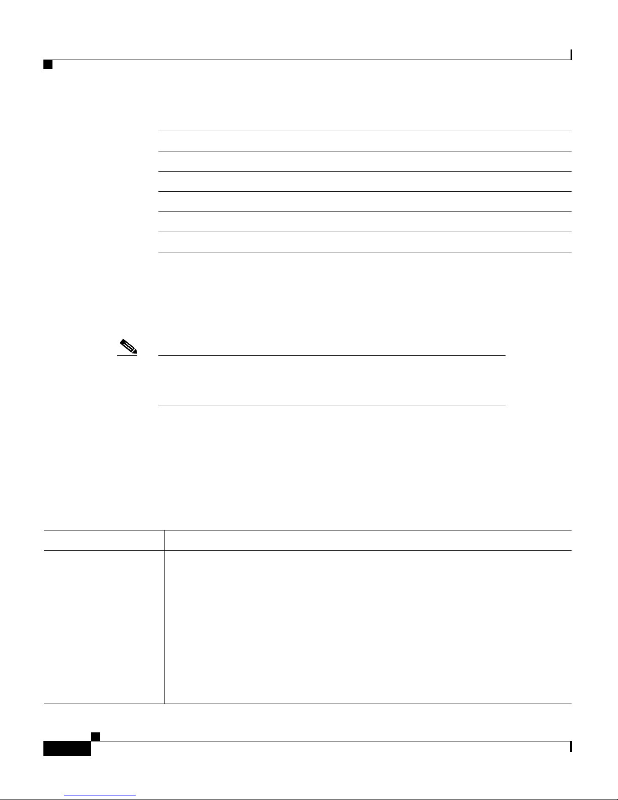
Figure 1-3 4-Port100BaseFX Modules
For connector and schematic information, see “100BaseFX and 1000BaseX
Modules Cabling” in Appendix B, “Connectors and Cables.”
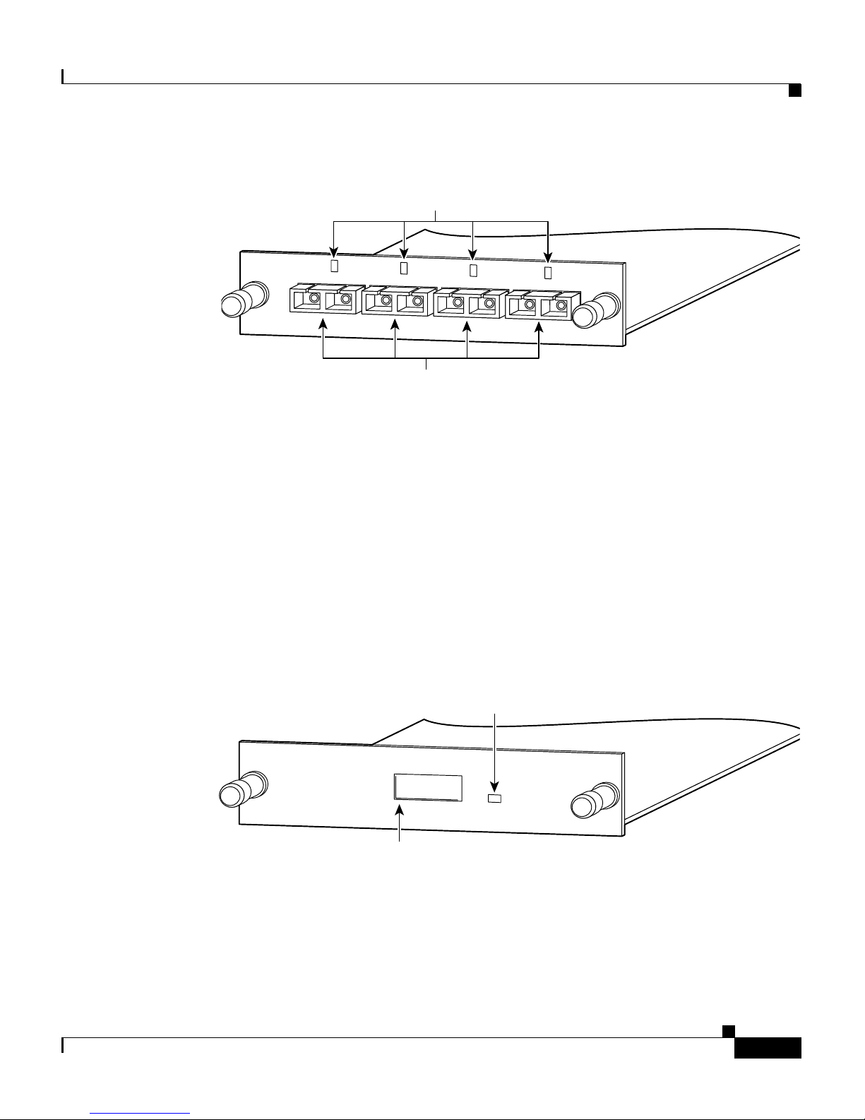
1000BaseX Module
The 1000BaseX module, shown in Figure 1-4, provides one switched 1000-Mbps,
full-duplex port that uses an SC fiber-optic connector. The port supports the IEEE
802.3z 1000BaseX standard. For connector and schematic information, see
“100BaseFX and 1000BaseX Modules Cabling” in Appendix B, “Connectors and
Cables.”
Figure 1-4 1000BaseX Module
15678
1X
2X
Four 100BaseFX ports
Tighten
Screws
To Activate
1
2
3
4
100BaseFX
LEDs
WS-X2924-XL-V
17696
1X
2X
Slot for
1000BaseX port
Tighten
Screws
To Activate
WS-X2931-XL
1000BaseX
LED
Page 12

Chapter 1 Overview
Key Features
1-6
Catalyst 2900 Series XL Modules Hardware Installation Guide
78-5912-03
GBICs for the 1000BaseX Module
You can install either a short-wavelength (SX) or a long-wavelength/long-haul
(LX/LH) GBIC into the 1000BaseX module. Figure 1-5 shows a GBIC, and the
GBIC types are listed in Table 1-2.
Figure 1-5 GBIC
Note GBICs are sold separately from the 1000BaseX modules. Cisco
supports some approved third-party GBICs. For more information,
refer to the Catalyst GigaStack Gigabit Interface Converter
Hardware Installation Guide.
The GBICs fit through cutouts in the front of the module and plug into connectors
on the module.
Ta b l e 1- 2 G B I C Ty p e s
GBIC Part Number
Short wavelength (SX) WS-G5484=
Long wavelength/long-haul
(LX/LH)
WS-G5486=
11825
Receiver Transmitter
Page 13

1-7
Catalyst 2900 Series XL Modules Hardware Installation Guide
78-5912-03
Chapter 1 Overview
Key Features
Figure 1-6 1000BaseX Module with GBIC Installed
1000BaseT Module
The 1000BaseT module, shown in Figure 1-7, provides one switched 1000-Mbps,
full-duplex port over UTP copper cabling. The 1000BaseT module port supports
the IEEE 802.3ab standard.
Figure 1-7 1000BaseT Module
The “10/100 Module Cabling” section in the “Connectors and Cables” appendix
describes the RJ-45 connector.
15688
1X
2X
1000BaseX port
Tighten
Screws
To Activate
WS-X2931-XL
1000BaseX
LED
31117
1000BaseT port
Tighten
Screws
To Activate
WS-X2932-XL
LED
1000BaseT
Page 14

Chapter 1 Overview
LEDs
1-8
Catalyst 2900 Series XL Modules Hardware Installation Guide
78-5912-03
LEDs
An LED above or next to each port reflects the port status, as described in
Table 1-3 .
Cabling Guidelines
This section describes the cabling guidelines you need to consider when planning
your network.
10/100 Module
The 10/100 ports require Category 5 UTP cabling. Attached devices must be
within 100 meters of the port and be either 10BaseT or 100BaseTX compatible.
Ta b l e 1- 3 Po r t L E D s
Color Meaning
Off No link.
Green Link present.
Flashing
green
Activity; port is transmitting or receiving data.
Alternating
green-amber
The port is experiencing error frames that can affect
connectivity. The port monitors errors such as excessive
collisions, cyclic redundancy check (CRC) errors, and alignment
errors.
Amber Port is not forwarding because
• It is initializing
• It was disabled by management or by an address violation
• It was blocked by Spanning Tree Protocol
Page 15

1-9
Catalyst 2900 Series XL Modules Hardware Installation Guide
78-5912-03
Chapter 1 Overview
Cabling Guidelines
The 10/100 ports are numbered 1X through 4X. The X indicates that the pins on
the port connector are internally crossed. If you are connecting to a device with
ports marked with an X, such as another switch or hub, use a crossover cable. If
you are connecting to devices with ports not marked with an X, such as a PC,
workstation, or server, use a straight-through cable.
For the connector pinouts and schematics, see the section “10/100 Module
Cabling” in Appendix B, “Connectors and Cables.”
Note Always observe the following general rules when connecting
devices: Use a straight-through cable to connect two ports when one
is designated with an X; use a crossover cable to connect two ports
when both are designated with an X.
100BaseFX Modules
The 100BaseFX ports use 50/125- or 62.5/125-micron multimode fiber-optic
cabling with duplex SC connectors. When set to run in full-duplex mode,
100BaseFX module ports can connect to compatible devices over distances of up
to 2 kilometers. For connector and schematic information, see Appendix B,
“Connectors and Cables.”
1000BaseX Modules
GBICs require the following fiber-optic cables with duplex SC connectors.
Table 1-4 GBIC Cable Specifications
GBIC Wavelength (nm) Fiber Type
Core Size
(micron)
Modal
Bandwidth
(MHz.km)
Cable Distance
Maximum
Shortwave (SX) 850 MMF 62.5
62.5
50.0
50.0
160
200
400
500
722 ft (220 m)
902 ft (275 m)
1640 ft (500 m)
1804 ft (550 m)
Page 16

Chapter 1 Overview
Deployment Examples
1-10
Catalyst 2900 Series XL Modules Hardware Installation Guide
78-5912-03
1000BaseT Module
The 1000BaseT port requires Category 5 UTP cabling. Attached devices must be
within 100 meters of the port and be 1000BaseT compatible.
For the connector pinouts and schematics, see the section “1000BaseT Module
Connectors” in Appendix B, “Connectors and Cables.”
Deployment Examples
This section describes five examples that use Catalyst 2900 series modules:
• Network with gigabit uplink
• Aggregating traffic from switched and shared networks
• Fast EtherChannel backbone
• Small to medium-sized LAN backbone
• High-performance client-server workgroups
Longwave/Long-haul
(LX/LH) (Patch cord
installation is required
for distances exceeding
300 m.)
1300 MMF 62.5
50.0
50.0
500
400
500
1804 ft (550 m)
1804 ft (550 m)
1804 ft (550 m)
Longwave/Long-haul
(LX/LH)
1300 SMF
(LX/LH)
9/10 32,810 ft (10 km)
Table 1-4 GBIC Cable Specifications (continued)
GBIC Wavelength (nm) Fiber Type
Core Size
(micron)
Modal
Bandwidth
(MHz.km)
Cable Distance
Maximum
Page 17

1-11
Catalyst 2900 Series XL Modules Hardware Installation Guide
78-5912-03
Chapter 1 Overview
Deployment Examples
Gigabit Uplink
Figure 1-8 shows a ultra-high-performance client-server workgroup. Catalyst
2900 series switches with 10/100, 1000BaseX, and 1000BaseT modules installed
connect the PCs and create a gigabit Ethernet or gigabit EtherChannel link to an
ultra-high-performance server supporting the Fast EtherChannel feature.
Figure 1-8 Gigabit Uplink Client-Server Workgroup
17698
Catalyst 2924M XL
switch with
1000BaseX or
1000BaseT
modules
Catalyst 2924M XL switch with
100BaseTX or
Fast EtherChannel
FastHub
400 series
Gigabit Ethernet
or Gigabit EtherChannel
100BaseTX
10BaseT/
100BaseTX
10BaseT/
100BaseTX
Catalyst 1900 or
Catalyst 2820 series
10/100 PCs
Ultra high-performance
servers
Catalyst 85xx, 6xxx,
5xxx, 4xxx
10/100 PCs
10BaseT
10BaseT PCs
Page 18

Chapter 1 Overview
Deployment Examples
1-12
Catalyst 2900 Series XL Modules Hardware Installation Guide
78-5912-03
Wiring Closet Aggregator
Figure 1-9 shows a Catalyst 2924M XL switch aggregating traffic from shared
10BaseT, switched 100BaseTX, and switched 10BaseT networks. A 100BaseFX
module passes the traffic to a backbone switch or router, and a 10/100 module
links the switch through a Fast EtherChannel link to a high-performance server.
Figure 1-9 Wiring Closet Aggregator
S6769
Catalyst 2924M XL
with 1000Base X or
1000Base T modules
100BaseTX
PCs
10BaseT
PCs
Catalyst 6500
High-performance
server
Catalyst 1900
FastHub 400
stack
Fast/Gigabit
EtherChannel
links
Fast/Gigabit
EtherChannel
links
Switched
100BaseTX links
Shared
100BaseTX links
Switched
10BaseT links
Page 19

1-13
Catalyst 2900 Series XL Modules Hardware Installation Guide
78-5912-03
Chapter 1 Overview
Deployment Examples
Fast or Gigabit EtherChannel Backbone
Figure 1-10 shows three Catalyst 2924M XL switches creating a high-speed
backbone for 10/100 PCs, Catalyst 2820 or Catalyst 1900 series switches, and
stacked FastHub 100BaseTX repeaters.
Figure 1-10 Fast EtherChannel Backbone
Backbone for Small- to Medium-Sized LAN
Figure 1-11 shows a Catalyst 2924M XL switch used as a corporate network
backbone of a small to medium-sized LAN, providing high-speed access to the
corporate servers using the Fast EtherChannel link.
This configuration provides a cost-effective migration path from legacy shared
10-Mbps networks to switched Fast Ethernet and gigabit Ethernet networks.
S6768
Catalyst 2924M XL
switches connected
via Fast/Gigabit
EtherChannel links
10/100
workstations
Catalyst 2820 or
Catalyst 1900 series
FastHub 400 series
Page 20

Chapter 1 Overview
Deployment Examples
1-14
Catalyst 2900 Series XL Modules Hardware Installation Guide
78-5912-03
Figure 1-11 Small- to Medium-Sized LAN Backbone
31670
Catalyst 2924M XL
Legacy
10BaseT Hub
FastHub
10/100 Hub
Gigabit Ethernet,
Fast EtherChannel
or 100BaseTX
Catalyst 1900 or
Catalyst 2900 XL
Switches
Workstations/Servers
Page 21

1-15
Catalyst 2900 Series XL Modules Hardware Installation Guide
78-5912-03
Chapter 1 Overview
Deployment Examples
High-Performance Workgroup
Figure 1-12 shows a high-performance client-server workgroup. A Catalyst
2924M XL switch with a 10/100 module installed connects the PCs and creates a
four-port Fast EtherChannel link to a high-performance server supporting Fast
EtherChannel.
Figure 1-12 High-Performance Client-Server Workgroup
S6770
Catalyst 2924M XL
with 10/100 module
10Base T or
100BaseTX PCs
Fast/Gigabit
EtherChannel links
Switched full-duplex
10BaseT/100BaseTX links
High-performance
server
Page 22

Chapter 1 Overview
Deployment Examples
1-16
Catalyst 2900 Series XL Modules Hardware Installation Guide
78-5912-03
Page 23

CHAPTER
2-1
Catalyst 2900 Series XL Modules Hardware Installation Guide
78-5912-03
2
Installation
This chapter describes how to install, connect, and remove the Catalyst 2900
series 10/100, 100BaseFX, 1000BaseX, and 1000BaseT modules.
These modules can be installed while the switch is running and require no
configuration. A power-on self-test (POST) verifies that the module is running
properly before any packets are forwarded.
You can manage module ports the same way you manage fixed ports on the
switch. The web-based Switch Manager is a graphical user interface for
monitoring and controlling port features, and you can use the console port or
Telnet to access the Cisco IOS command-line interface.
Inspecting the Packing List
Before you install a 10/100, 100BaseFX, 1000BaseX, or 1000BaseT module,
ensure that the following items are included in the package:
• Catalyst 2900 series XL module
• Cisco Information Packet
• One CD-ROM containing the Flash image to upgrade the software for the
Catalyst 2900 series switch and the corresponding documentation.
If anything is missing, contact your Cisco Systems customer service
representative.
Page 24

Chapter 2 Installation
EMC Regulatory Statements
2-2
Catalyst 2900 Series XL Modules Hardware Installation Guide
78-5912-03
EMC Regulatory Statements
U.S.A.
U.S. regulatory information for this product is in the front matter of this manual.
For translated warnings, see Appendix C, “Translated Safety Warnings.”
Taiwan
Avoiding Electrostatic Discharge
Before you install the module, ground yourself by touching a piece of metal to
avoid electrostatic discharge (ESD). You should also take the following
precautions to prevent damage to the board:
• Keep the module in its antistatic shielded bag until you are ready to install it.
• Handle the modules by the edges.
• Do not touch the components, pins, leads, or solder connections.
Installing a Module
The switch expansion slots are numbered 1 (left) and 2 (right). You can install
either of the modules into either slot. Blank faceplates on the Catalyst 2924M XL
switch cover the slots, as shown in Figure 2-1
Page 25

2-3
Catalyst 2900 Series XL Modules Hardware Installation Guide
78-5912-03
Chapter 2 Installation
Installing a Module
Caution When installing a 100BaseFX or 1000BaseX module, do not remove
the rubber plugs from the fiber-optic port or the rubber caps from the
fiber-optic cable until you are ready to connect the cable. The plugs
and caps protect the fiber-optic port and cable from contamination
and ambient light.
To remove a faceplate, follow these steps:
Step 1 Loosen the thumbscrews attaching the faceplate to the switch.
Step 2 Remove the faceplate from the switch, and store it for future use. Figure 2-1
shows a Catalyst 2924M XL switch with an empty expansion slot.
Figure 2-1 Catalyst 2924M XL Switch with an Empty Expansion Slot
After you have removed the faceplate, follow these steps to install a module in the
empty expansion slot.
Warning
Class 1 laser product.
Warning
Avoid exposure to the laser beam.
H11051
1x
2x
3x
4x
5x
6x
7x 8x
9x
10x
11x
12x
13x
14x 15x
16x
17x
18x
19x 20x 22x
24x
21x
23x
10B
aseT
/1
00
B
aseT
x
MODE
SERIES
XL
Slot 1 with blank
faceplate
Thumbscrews
Slot 2 with
faceplate off
Page 26

Chapter 2 Installation
Installing a Module
2-4
Catalyst 2900 Series XL Modules Hardware Installation Guide
78-5912-03
Step 3 Slide the module into the slot card-guides until you feel it touch the back of the
unit.
Step 4 Push the module firmly until it snaps into place.
Step 5 Tighten the thumbscrews on the module faceplate. The module begins running
POST when the thumbscrews are tightened.
Note The installation is not complete until the thumbscrews are
tightened.
Step 6 Ensure that the STATUS LED is green (module operational).
Step 7 If the module is not operational, reseat it. If the module still is not operational,
contact Cisco Systems for a replacement.
Handling a GBIC
Following are the Gigabit Interface Converter (GBIC) handling guidelines:
• GBICs are static sensitive. To prevent ESD damage, follow appropriate board
and component handling procedures.
• GBICs are dust sensitive. When storing a GBIC or when a fiber-optic cable is
not plugged in, always keep plugs in the GBIC optical bores.
• The most common source of contaminants in the optical bores is debris
picked up on the ferrules of the optical connectors. Use an alcohol swab or
Kim-Wipe to clean the ferrules of the optical connector.
Page 27

2-5
Catalyst 2900 Series XL Modules Hardware Installation Guide
78-5912-03
Chapter 2 Installation
Installing a Module
Installing a GBIC
1000BaseX modules are shipped without GBICs installed.
Note GBICs are hot-swappable in 1000BaseX modules.
Caution Before you install the GBIC, ground yourself by touching a piece of
metal to avoid electrostatic discharge.
To install a GBIC, do the following:
Step 1 Remove the GBIC from its protective packaging.
Step 2 Verify that the GBIC is the correct type for your network by checking the part
number. The number indicates whether it is a 1000BaseSX, 1000BaseLX/LH, or
ZX.
Step 3 Grip the sides of the GBIC with your thumb and forefinger, and insert it into the
slot on the front panel of the 1000BaseX module, as shown in Figure 2-2.
Figure 2-2 GBIC Insertion
Note GBICs are keyed to prevent incorrect insertion.
17697
1X
2X
1000BaseX
Slot for
1000BaseX port
GBIC
Tighten
Screws
To Activate
WS-X2931-XL
Ethernet
Tx
LED
Page 28

Chapter 2 Installation
Connecting to Module Ports
2-6
Catalyst 2900 Series XL Modules Hardware Installation Guide
78-5912-03
Warning
Class 1 laser product.
Warning
Avoid exposure to the laser beam.
Step 4 When you are ready to attach the network interface fiber-optic cable, remove the
plug from the GBIC, and save it for future use.
Connecting to Module Ports
Insert a connector according to the type of module (100BaseFX,
10/100/1000BaseT, or 1000BaseX), as follows:
• RJ-45 connector (10/100 and 1000BaseT modules)
Insert the RJ-45 connector until it snaps into place, as shown in Figure 2-3.
• Fiber-optic port (100BaseFX and 1000BaseX SC modules)
Remove the rubber plugs from the fiber-optic port on the module and store
them for future use. Insert the connector in the fiber-optic receptacle, as
shown in Figure 2-5.
Note The port status LED is amber while Spanning Tree Protocol
discovers the topology and searches for loops. This takes about
30 seconds. The port status LED then turns green.
Page 29

2-7
Catalyst 2900 Series XL Modules Hardware Installation Guide
78-5912-03
Chapter 2 Installation
Connecting to Module Ports
Figure 2-3 Inserting an RJ-45 Connector into a 10/100 Module
Figure 2-4 Inserting an RJ-45 Connector into a 1000BaseT Module
15x
16x
H11054
Tighten
Screws
To Activate
17x
18x
19x
20x 22x
24x
21x
23x
1x
2x
3x
4x
10BaseT/100BaseTX
WS-X2914-XL-V
SERIES
XL
15x
16x
31338
Tighten
Screws
To Activate
17x
18x
19x
20x
22x
24x
21x
23x
WS-X2932-XL
SERIES
XL
1000BaseT
Page 30

Chapter 2 Installation
Connecting to Module Ports
2-8
Catalyst 2900 Series XL Modules Hardware Installation Guide
78-5912-03
Note Always use a straight-through cable when connecting to a PC,
server, or workstation. Use a crossover cable to connect to another
switch or hub. See the section “10/100 Module Cabling” in
Appendix B, “Connectors and Cables.”
Figure 2-5 Inserting an SC Connector into a 100BaseFX or 1000BaseX SC Module
Using a Patch Cord with the GBICs
When using the LX/LH GBIC with 62.5-micron diameter multimode fiber
(MMF), you must install a mode-conditioning patch cord (Cisco product number
CAB-GELX-625 or equivalent) between the GBIC and the MMF cable on both
the transmit and receive ends of the link for link distances greater than 984 feet
(300 meters).
Note You must use the patch cord to comply with the IEEE 802.3z
standards. Using the LX/LH GBIC with MMF and no patch cord for
very short link distances (tens of meters) is not recommended. The
result could be an elevated bit error rate (BER).
H11053
1x
2x
3x
4x
5x
6x
7x 8x
9x
10x
11x
12x
13x
14x 15x
16x
17x
18x
19x 20x 22x
24x
21x
23x
10B
ase
T
/1
0
0B
as
eT
x
MODE
100BaseFX
Tighten
Screws
To Activate
100BaseFX
1
2
W
S
-X
292
2-X
L-V
SERIES
XL
WS-X2931-XL
Tx
Rx
Tighten
S
crew
s
To Activate
Page 31

2-9
Catalyst 2900 Series XL Modules Hardware Installation Guide
78-5912-03
Chapter 2 Installation
Connecting to Module Ports
Patch Cord Configuration Example
Following is a typical configuration example:
Figure 2-6 Patch Cord Example
Installing the Patch Cord
Figure 2-7 shows the connectors on the patch cord. Connect the end of the patch
cord labeled “To Equipment” into the GBIC. Connect the end labeled “To Cable
Plant” into the patch panel. The patch cord is 9.84 feet (3 meters) long and has
duplex SC male connectors at each end.
Figure 2-7 Patch Cord Cabling
1000BaseLX/LH
port
Patch
panel
Link span greater than 984 ft
(300 m)
1000BaseLX/LH
port
RX
TX
Patch
panel
Patch
cord
Building
cable plant
TX
RX
Patch
cord
18291
To equipment To cable plant
13089
Page 32

Chapter 2 Installation
Connecting to Module Ports
2-10
Catalyst 2900 Series XL Modules Hardware Installation Guide
78-5912-03
Default Settings for the 1000BaseX and 1000BaseT modules
The 1000BaseX and 1000BaseT modules have the same default settings as the
10/100 and 100BaseFX modules, with the following exception:
• port cost value
The Spanning Tree Protocol (STP) uses port path costs to determine which
port to select as a forwarding port. Ports attached to faster media (such as
1000BaseX) have lower numbers assigned to them by default, and ports
attached to slower media have higher numbers assigned. The default port cost
value for 1000BaseX and 1000BaseT ports is 4.
Removing a GBIC
To remove a GBIC, do the following:
Step 1 Disconnect the network fiber cable from the GBIC SC connector.
Step 2 Release the GBIC from the slot by simultaneously squeezing the two plastic tabs
(one on each side of the GBIC).
Step 3 Slide the GBIC out of the Gigabit Ethernet module slot. A flap drops down to
protect the Gigabit Ethernet module connector.
Step 4 If the GBIC is defective, dispose of the product.
Warning
Ultimate disposal of this product should be handled according to
all national laws and regulations.
Page 33

2-11
Catalyst 2900 Series XL Modules Hardware Installation Guide
78-5912-03
Chapter 2 Installation
Removing a Module
Removing a Module
To remove a module, follow these steps:
Step 1 Disconnect the cable from the module port.
Caution Catalyst 2900 series modules are “hot swappable,” provided that you
disconnect the cable from the module port before removing the
module from the switch. Removing the module before disconnecting
the module port cable(s) can result in a reboot or crash of the switch.
Step 2 Loosen the thumbscrews attaching the module faceplate to the switch.
Step 3 Remove the module by grasping the thumbscrews and pulling the module out of
the slot.
Caution Replace the rubber plugs in the fiber-optic connector on the module
and the rubber caps on the fiber-optic connector on the cable. The
plugs and caps protect the fiber-optic connectors from
contamination and ambient light.
Step 4 Replace the blank faceplate to cover the empty expansion slot.
Step 5 Tighten the thumbscrews on the faceplate.
Power-On Self-Test
When a module is inserted into the expansion slot, the port LEDs on the module
turn amber. After the module thumbscrews are tightened, the LEDs turn off and
then turn green. Starting from the left-most LED, the LEDs turn off in turn as
POST completes successfully. When all the LEDs are off, the LEDs blink green
and begin normal operations.
If a module fails POST, the expansion slot LED (1 or 2) on the switch turns amber.
All POST failures are fatal. Call Cisco Systems if a module fails POST.
Page 34

Chapter 2 Installation
Power-On Self-Test
2-12
Catalyst 2900 Series XL Modules Hardware Installation Guide
78-5912-03
Note If you power up a Catalyst 2912MF XL, Catalyst 2916M XL, or
Catalyst 2924M XL switch with modules installed, the module ports
are the last to run POST.
Page 35

CHAPTER
3-1
Catalyst 2900 Series XL Modules Hardware Installation Guide
78-5912-03
3
Troubleshooting
Use Table 3-1 to identify problems with the modules and take the appropriate
corrective action.
Table 3-1 Common Problems and Their Solutions
Symptom Possible Causes Corrective Action
Port LED is
amber.
Thumbscrews have not been
tightened.
Tighten thumbscrews.
Spanning Tree Protocol is
checking for loops.
Wait for Spanning Tree Protocol to complete
its search. The LED turns green when
Spanning Tree Protocol completes its check.
Port is initializing, it was disabled
by management or an address
violation, or it was blocked by
Spanning Tree Protocol.
Use Visual Switch Manager or the IOS
command-line interface to check the status of
the port and to enable it.
Port LED is
alternating
between green and
amber.
Port is experiencing error frames.
This could be due to a duplex
mismatch caused by
autonegotiation, collisions, CRC
errors, or alignment errors.
Check the duplex settings on both devices.
Check the speed settings on both devices
except when using a gigabit Ethernet module.
You cannot change the speed on the gigabit
Ethernet modules. If one parameter is
manually set, manually set all of them, or set
both devices to autonegotiate speed and
duplex. See the Catalyst 2900 Series XL
Installation and Configuration Guide for
more information.
Page 36

Chapter 3 Troubleshooting
3-2
Catalyst 2900 Series XL Modules Hardware Installation Guide
78-5912-03
Port LED is off. Device has no power. Ensure that the switch and the target device
have power.
Wrong cable type. Verify that the cable is correct: crossover or
straight-through.
Bad cable.
No cable.
Replace with a known good cable.
Insert and connect cable.
Expansion slot
LED is amber.
Module failed POST. Ensure that the switch is running an IOS
software release that supports the module.
(See “Key Features” in Chapter 1,
“Overview.”) If the IOS software release is
correct, call Cisco Systems to replace the
module.
Switch crashes or
reboots
Removed the module before
disconnecting the module port
cables.
Reset switch (if the switch doesn’t reset
itself). When hot swapping the module,
disconnect the cable from the module port
before removing the module from the switch.
Table 3-1 Common Problems and Their Solutions (continued)
Symptom Possible Causes Corrective Action
Page 37

A-1
Catalyst 2900 Series XL Modules Hardware Installation Guide
78-5912-03
APPENDIX
A
Technical Specifications
This appendix lists the technical specifications and regulatory agency approvals
for the Catalyst 2900 series modules.
Environmental Ranges
Operating temperature
10BaseT, 100BaseTX,
100BaseFX, 1000BaseX modules
32 to 122°F (0 to 50°C)
1000BaseT module –23 to 113°F (–5 to 45°C)
Storage temperature
10BaseT, 100BaseTX,
100BaseFX, 1000BaseX modules
–4 to 149°F (–20 to 65°C)
1000BaseT module –13 to 158°F (–25 to 70°C)
Operating humidity
10BaseT, 100BaseTX,
100BaseFX, 1000BaseX modules
10 to 85% (noncondensing)
1000BaseT module 10 to 90% (noncondensing)
Storage humidity
10BaseT, 100BaseTX,
100BaseFX, 1000BaseX modules
5 to 95% (noncondensing)
1000BaseT module 5 to 95% (noncondensing)
Page 38

Appendix A Technical Specifications
A-2
Catalyst 2900 Series XL Modules Hardware Installation Guide
78-5912-03
Operating altitude
10BaseT, 100BaseTX,
100BaseFX, 1000BaseX modules
Up to 10,000 ft (3048 m)
1000BaseT module Up to 10,000 ft (3048 m)
Storage altitude
10BaseT, 100BaseTX,
100BaseFX, 1000BaseX modules
Up to 15,000 ft (4570 m)
1000BaseT module Up to 30,000 ft (9114 m)
Power Consumption
Module Type Current
10/100 6.60W
100BaseFX 8.40W (two ports)
11.85W (four ports)
1000BaseX 11.2W
1000BaseT 15.5W
Physical Dimensions
Height x Width x Depth 1.25 x 5.75 x 10.3 in.
(3.18 x 14.61 x 26.16 cm)
Weight 10.1 oz (0.29 kg)
Agency Approvals
Safety EMI
AS/NZS 3260, TS001 FCC Part 15 Class A
UL 1950/CSA 22.2 No. 950 EN 55022A Class A (CISPR 22
Class A)
IEC 950/EN 60950 VCCI Class A
CE AS/NRZ 3548 Class A
BCIQ
CE Class A
Page 39

B-1
Catalyst 2900 Series XL Modules Hardware Installation Guide
78-5912-03
APPENDIX
B
Connectors and Cables
This appendix describes the cables and connectors for the Catalyst 2900 series
modules.
10/100 Module Cabling
The 10/100 module ports are marked with an X, indicating that they have their
transmit (TD) and receive (RD) signals internally crossed for attachment of an
Ethernet adapter using a straight-through cable.
When connecting the 10/100 ports to 10BaseT or 100BaseTX servers and
workstations, ensure that you use a Category 5 straight-through cable. When
connecting to other switches or repeaters, ensure that you use a crossover cable.
The schematics of crossover and straight-through cables are shown in Figure B-1.
Figure B-1 Crossover and Straight-Through Cable Schematics
Switch
3 TD+
6 TD–
1 RD+
2 RD–
Switch
3 TD+
6 TD–
1 RD+
2 RD–
H5579
Page 40

Appendix B Connectors and Cables
10/100 Module Connectors
B-2
Catalyst 2900 Series XL Modules Hardware Installation Guide
78-5912-03
Note Always observe the following general rules when connecting
devices: use a straight-through cable to connect two ports when one
is designated with an X; use a crossover cable to connect two ports
when both are designated with an X.
10/100 Module Connectors
The 1000BaseT module has one or more RJ-45 connectors on the front panel.
Figure B-2 shows the pinout.
Figure B-2 10/100BaseT RJ-45 Connector
Page 41

B-3
Catalyst 2900 Series XL Modules Hardware Installation Guide
78-5912-03
Appendix B Connectors and Cables
1000BaseT Module Connectors
1000BaseT Module Connectors
The 1000BaseT module has one RJ-45 connector on the front panel. Figure B-3
shows the pinout.
Figure B-3 1000BaseT RJ-45 Connector
100BaseFX and 1000BaseX Modules Cabling
The 100BaseFX and the 1000BaseX modules use duplex SC connectors. This type
of connector is shown in Figure B-4.
Figure B-4 100BaseFX and 1000BaseX SC Connector
1 2 3 4 5 6 7 8
Pin Label
1
2
3
4
5
6
7
8
TP0+
TP0-
TP1+
TP2+
TP2-
TP1-
TP3+
TP3-
34751
H8707
Tx Rx
Page 42

Appendix B Connectors and Cables
100BaseFX and 1000BaseX Modules Cabling
B-4
Catalyst 2900 Series XL Modules Hardware Installation Guide
78-5912-03
Page 43

C-1
Catalyst 2900 Series XL Modules Hardware Installation Guide
78-5912-03
APPENDIX
C
Translated Safety Warnings
This appendix repeats in multiple languages the warnings in this guide.
Class 1 Laser Product Warning
Warning
Class 1 laser product.
Waarschuwing
Klasse-1 laser produkt.
Varoitus
Luokan 1 lasertuote.
Attention
Produit laser de classe 1.
Warnung
Laserprodukt der Klasse 1.
Avvertenza
Prodotto laser di Classe 1.
Advarsel
Laserprodukt av klasse 1.
Aviso
Produto laser de classe 1.
Page 44

Appendix C Translated Safety Warnings
Laser Beam Exposure Warning
C-2
Catalyst 2900 Series XL Modules Hardware Installation Guide
78-5912-03
Laser Beam Exposure Warning
¡Advertencia!
Producto láser Clase I.
Varning!
Laserprodukt av klass 1.
Warning
Avoid exposure to the laser beam.
Waarschuwing
Vermijd blootstelling aan de straal.
Varoitus
Vältä säteelle altistumista.
Attention
Eviter toute exposition au faisceau.
Warnung
Schützen Sie sich vor Strahlung.
Avvertenza
Evitare l’esposizione al raggio.
Advarsel
Unngå å bli utsatt for strålen.
Aviso
Evite exposição ao raio.
¡Advertencia!
Evitar la exposición al haz.
Varning!
Utsätt dig inte för laserstrålningen.
Page 45

C-3
Catalyst 2900 Series XL Modules Hardware Installation Guide
78-5912-03
Appendix C Translated Safety Warnings
Product Disposal
Product Disposal
Warning
Ultimate disposal of this product should be handled according to
all national laws and regulations.
Waarschuwing
Het uiteindelijke wegruimen van dit product dient te geschieden
in overeenstemming met alle nationale wetten en reglementen.
Varoitus
Tämä tuote on hävitettävä kansallisten lakien ja määräysten
mukaisesti.
Attention
La mise au rebut ou le recyclage de ce produit sont généralement
soumis à des lois et/ou directives de respect de l'environnement.
Renseignez-vous auprès de l'organisme compétent.
Warnung
Die Entsorgung dieses Produkts sollte gemäß allen
Bestimmungen und Gesetzen des Landes erfolgen.
Avvertenza
Lo smaltimento di questo prodotto deve essere eseguito secondo
le leggi e regolazioni locali.
Advarsel
Endelig kassering av dette produktet skal være i henhold til alle
relevante nasjonale lover og bestemmelser.
Aviso
Deitar fora este produto em conformidade com todas as leis e
regulamentos nacionais.
¡Advertencia!
Al deshacerse por completo de este producto debe seguir todas
las leyes y reglamentos nacionales.
Varning!
Vid deponering hanteras produkten enligt gällande lagar och
bestämmelser.
Page 46

Appendix C Translated Safety Warnings
Product Disposal
C-4
Catalyst 2900 Series XL Modules Hardware Installation Guide
78-5912-03
 Loading...