

Page 1

Hardware Installation Guide for the Cisco 1100 Series Integrated
Services Router
Last Modi fied: 2018-04-04
Americas Headquarters
Cisco Systems, Inc.
170 West Tasman Drive
San Jose, CA 95134-1706
USA
http://www.cisco.com
Tel: 408 526-4000
800 553-NETS (6387)
Fax: 408 527-0883
Page 2

©
2017-2017 Cisco Systems, Inc. Al l rights reserved.
Page 3

CON TEN T S
Pr e f ac e
CH A PT ER 1
Preface vii
Audience vii
Document Organi zation vii
Document Conventions viii
Related Documentation ix
Obtaining Documentation and Submitting aService Request x
Overview of Cisco 1000 Ser ies Integr ated Servi ces Routers 1
Overview 1
About Cisco 1100 SeriesIntegrated Service Routers 1
ChassisViews 2
Labels on the Router 3
For Addi tional Help Locating Labels on the Router 4
Hardware Features 4
InterfacePorts 4
Power-over-Ethernet (PoE) 5
LED Indicators 5
CH A PT ER 2
Reset Button 10
Sl otsand Interfaces 10
About Slots, Subslots, and Port Numbering 10
Subslot/Bay Numbering 11
Specification 11
Periodic Inspection and Cleaning 14
Preparing for Router I nstall ation 15
Prepari ng for Router Installation 15
Safety Recommendations 15
Hardware Install ation Guide for the Ci sco 1100 Series Integrated Services Router
iii
Page 4

Contents
Safety With Electricity 15
Preventing Electrostatic Discharge Damage 16
General SiteRequirements 16
Si te Selecti on Guidelines 17
Rack Requirements 17
Router Environmental Requirements 17
Power Guidelines and Requi rements 18
Network Cabling Specifications 18
Console Port Connections 19
EIA/TIA-232 19
USB Serial Console 19
Console Port Considerations 20
Prepari ng for Network Connections 20
Ethernet Connections 20
CH A PT ER 3
Required Tools and Equipment for Installation and Maintenance 20
Installation Checklist 21
Creating a SiteLog 22
Installing and Connecting the Router 23
Installi ng and Connecting the Router 23
Safety Warnings 23
What You Need to Know 23
Bef oreYou Begin 24
Unpacking theRouter 24
Installi ng the Router 24
Installi ng a Cisco 1100 Series I SR 24
Attaching theChassis 25
Mounti ng on theWall 25
Attaching DIN Rail Brackets 28
Mounti ng the Router in aRack 30
Setting the Chassis on a Desktop 31
Chassis Grounding 31
Connecting to aConsole Terminal or Modem 32
Connecting to the Serial Port with Microsoft Windows 33
Connecting to the Console Port with Mac OS X 34
Hardware Installation Guide for the Ci sco 1100 Seri es Integrated Services Router
iv
Page 5

Contents
Connecting to the Console Port with Linux 34
Installi ng the Cisco Microsof t WindowsUSB Device Driver 35
Installi ng the Cisco Microsoft WindowsXP USB Driver 35
Installi ng the Cisco Microsoft Windows2000 USB Driver 36
Installi ng the Cisco Microsoft WindowsVistaUSB Driver 36
Installi ng the Cisco Microsoft Windows8/Windows 10 USB Driver 36
Uninstall ing the Cisco Microsoft WindowsUSB Driver 37
Uninstalling theCisco Microsoft Windows XP and 2000 USB Driver 37
Uninstalling theCisco Microsoft Windows VistaUSB Driver 38
Connecting WAN and LAN Interfaces 38
Ports and Cabling 39
Connection Proceduresand Precauti ons 39
CH A PT ER 4
ROM M onitor Over view and Basic Procedures 41
ROM Monitor Overview and Basic Procedures 41
ROM Monitor Overview 41
Entering ROM Monitor Mode 42
Checking theCurrent ROMmon Version 42
Commonly Used ROM Moni tor Commands 43
Displaying the Avai lable ROM Monitor Commands 43
Examples 44
Changing the ROM Monitor Prompt 44
Displaying the Configuration Regi ster Setting 44
Environment Variable Settings 45
Frequently Used Envi ronmental Vari ables 45
Displaying Environment Variable Settings 45
Entering Environment Variable Settings 46
Saving Environment Variable Settings 46
Exiting ROM Monitor Mode 46
Confi guration Example 47
CH A PT ER 5
Upgrading theROMmon for aRouter 47
Installing and Upgrading Inter nal M odules and FRUs 49
Installi ng and Upgrading Internal Modules and FRUs 49
Safety Warnings 49
Hardware Install ation Guide for the Ci sco 1100 Series Integrated Services Router
v
Page 6

Contents
Accessi ng Internal Modules 49
Replacing theChassis Cover 50
Removing the Cover 50
Replacing theCover 51
Locating Internal and External Sl ots for Modules 51
Installi ng the Internal PoE Daughter Card 52
Removing and Replacing the Internal PoE Daughter Card 53
Removing and Replacing theUSB Flash Token Memory Stick 53
AC Power Supplies 54
Overview of theAC Power Supply 54
Installi ng and Removing SFP Modules 54
Installi ng SFPs 61
Removing SFP Modules 61
CH A PT ER 6
Declaration of Confor mity for RF Exposure 63
Declaration of Conformity of RF Exposure 63
Hardware Installation Guide for the Ci sco 1100 Seri es Integrated Services Router
vi
Page 7

Preface
Audience, page vii
•
Document Organization, page vii
•
Document Conventions, page vi ii
•
Related Documentation, page ix
•
Obtaining Documentation and Submitting aService Request, page x
•
Audience
Thisguideis intended for Ciscoequipment providersandservicepersonnel whoare technically knowledgeable
and famili ar with Cisco routers and Cisco I OSsoftware and features. They would understand how to install,
confi gure, and maintai n the router, and they should be famil iar with electronic circuitry and wiring practices,
and have experienceasan electronic or electromechanical technician. This guideidentifies certain procedures
that should be performed only by trained and qualified personnel.
Document Organization
This guide i ncludes the following chaptersand appendi x::
Chapter 1
Chapter 2
Chapter 3
DescriptionTitl eChapter//Appendix
Overview of theCisco
1100 Series ISR
Prepari ng for Router
Install ation
Install ing and
Connecting the Router
Hardware Install ation Guide for the Ci sco 1100 Series Integrated Services Router
Descri bes the router chassis views, general hardware
features, slot, port and interfaceinformation, and LED
indicators.
Descri bes siterequirementsandtheequipment needed
to install therouter.
Descri beshow toinstal l and connect therouter to LAN
and WAN.
vii
Page 8

Document Conventions
Preface
DescriptionTitl eChapter//Appendix
Chapter 4
Chapter 5
1
Field Replaceable Unit
Document Conventions
This document uses the following conventions:
^ or Ctrl
Italic font
ROM Monitor Overview
and Basic Procedures
InstallingandUpgrading
Inter nal Modules and
FRUs
DescriptionConvention
Both the^ symbol andCtrl represent theControl (Ctrl) key on a keyboard.
For example, the key combination ^D or Ctr l -D meansthat you hold
down the Control key while you press the D key. (Keys are indi cated in
capital letters but are not case sensitive.)
Commandsand keywords and user-entered text appear in bold font.bold font
Document titles, new or emphasized terms, andarguments for whichyou
supply values are i n italic font.
Provides an overview of ROM Monitor conceptsand
operations.
Descri bes how to install and upgradeinternal modules
and field replaceable units
1
on the router.
Courier font
...
|
[x | y]
{ x | y}
Terminal sessions andinformationthesystem displays appear in courier
font.
Bold Courier font indicates text that the user must enter.Bold Courier font
Elements in squarebrackets areoptional.[x]
An ellipsis (threeconsecutive nonbolded periodswithout spaces) after
a syntax element indicates that theel ement can berepeated.
A verti cal line, called a pipe, indicatesa choicewithin aset of keywords
or arguments.
Opti onal al ternativekeywordsare grouped in brackets and separated by
verti cal bars.
Required alternative keywords aregrouped in braces and separated by
verti cal bars.
viii
Hardware Installation Guide for the Ci sco 1100 Seri es Integrated Services Router
Page 9

Preface
Related Documentation
DescriptionConvention
[x { y | z} ]
Nested set of square brackets or braces indi cate optional or required
choices within optional or requi red elements. Braces and a vertical bar
within square brackets indicate a required choice within an optional
element.
stri ng
A nonquoted set of characters. Do not use quotation marks around the
stri ng or thestring will include the quotation marks.
Nonprinting characters such as passwords are in angle brackets.< >
Default responses to system promptsare in square brackets.[ ]
!, #
An exclamation point (!) or apound sign (#) at thebeginning of a line
of code indi cates a comment line.
Reader Alert Conventions
This document uses the following conventions for reader alerts:
Note
Meansreader takenote. Notes contain helpful suggestionsor references to material not covered in the
manual.
Meansthefollowing information will help you sol vea problem.Tip
Caution
Meansreader becareful. In this situation, you might do somethingthat could result in equipment damage
or loss of data.
Timesaver
Meansthedescribed action saves time. You can savetimeby performi ng the action descri bed in the
paragraph.
Warning
Meansreader bewarned. I n this situation, you might perfor m an action that could r esult in bodily
inj ur y.
Related Documentation
For related release documentation, see the following URLs:
Hardware Install ation Guide for the Ci sco 1100 Series Integrated Services Router
ix
Page 10

Preface
Obtaining Documentation and Submitting a Service Request
Cisco 1100 Series ISR Release Notes: https://www.cisco.com/c/en/us/td/docs/routers/access/1100/rel ease/
16-6-2/isr1k-rel-notes-xe-16-6.html
Cisco 1100 Series ISR Configuration Guide - https://www.cisco.com/c/en/us/td/docs/routers/access/1100/
software/configuration/guide/cisco_1100_series_swcfg.html
Obtaining Documentation and Submitting a Service Request
For informationon obtaining documentation, submitting aservicerequest, andgathering additional information,
seeWhat’s New in Ci sco Product Documentation at:
whatsnew.html
Subscribeto What’s New in Cisco Product Documentation, which listsall new and revised Cisco technical
documentation, asan RSS feed and del iver content directly to your desktop using a reader application. The
RSS feeds are a freeservice.
.
http://www.cisco.com/en/US/docs/general/whatsnew/
Hardware Installation Guide for the Ci sco 1100 Seri es Integrated Services Router
x
Page 11

Overview
CHA PTER
1
Overview of Cisco 1000 Series Integrated
Services Routers
Overview , page 1
•
Cisco1000 Series Integrated Services Routers(ISRs) with Cisco IOSXE Software combine Internet access,
comprehensive securi ty, and wireless services (LTE Advanced 3.0, Wireless WAN and WirelessLAN), are
high-performance devices that areeasy to deploy and manage. The routers are well suited for deployment as
customer premises equipment (CPE) in enterprisebranch offices, and i n service provider managed servi ce
environments.
TheCisco 1000 ISRs provideenterprisegrade-wired line-likefunctionali ty, such as qual ity of service (QoS)
for cell ular, Multi-VRF, advanced VPN, and unifi ed communicationssolutionsover LTE.
The1000 Series also provides the abi lity to extend Cisco product-based networks to remote offices with a
rel atively low incremental investment, aswel l asto enable managed services offerings based on end-to-end
Cisco system architecture.
About Cisco 1100 Series Integrated Service Routers
TheCisco 1100 SeriesISRs are fixed branch routersbased on theCisco IOS XE Everest 16.6.2 operating
system, with amulti-coreData Plane.
Thetwo types of platformssupported on Cisco 1100 Series I SRsare 8-port and 4-port platforms.
8-port platforms are high-performance, managed serviceprovider and enterpriseplatforms having:
8-port integrated front panel switch ports
•
Opti onal PoE on LAN daughter card with support up to 4PoE/2PoE+ports
•
Opti onal WLAN support - 802.11ac WAVE 2
•
4G LTE-Advanced support with carrier aggregation
•
Hardware Install ation Guide for the Ci sco 1100 Series Integrated Services Router
1
Page 12
Chassis Views
Chassis Views
Overview of Ci sco 1000 Series Integrated Services Routers
4-port platforms are midrangeperformance, managed service provider platforms and enterpriseplatforms
having:
4-port integrated front panel switch ports
•
VDSL2 and ADSL2/2+ support
•
Opti onal POE on LAN daughter card supporting 2PoE/1PoE+ ports
•
Opti onal WLAN support - 802.11ac WAVE 2
•
4G LTE-Advanced support with carrier aggregation
•
This section containsviewsof the front and back panelsof theCisco 1100 SeriesISR, showing locations of
thepower and si gnal interfaces, interface slots, statusindicators, and chassi s identification labels.
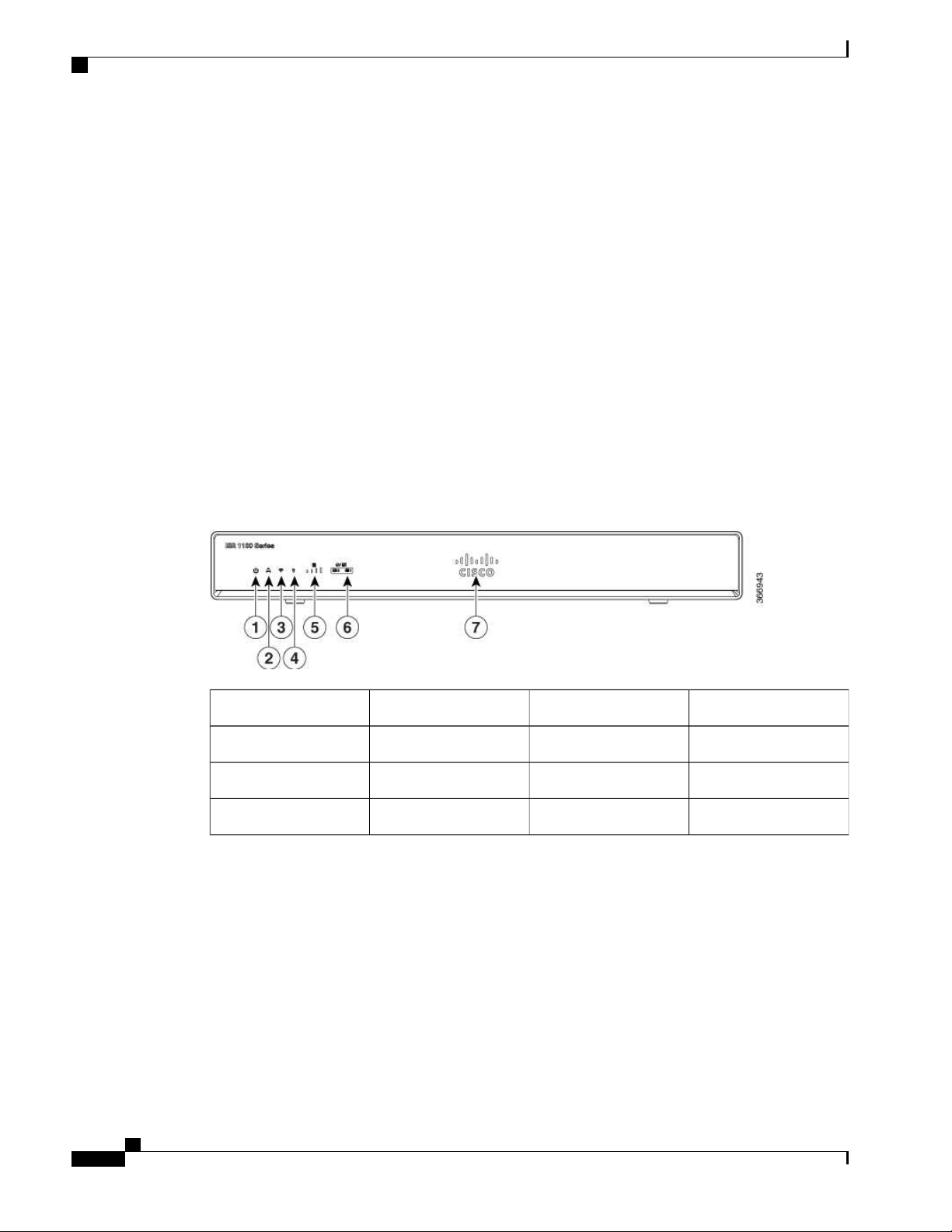
Bezel View
Figure 1: Cisco 1100 Series ISR - Bezel View
Illuminated Cisco Logo7
VPN2Status1
GPS4WiFi3
LTE Data/SIM6LTE Signal Intensity5
Hardware Installation Guide for the Ci sco 1100 Seri es Integrated Services Router
2
Page 13
Overview of Cisco 1000 Series Integrated Services Routers
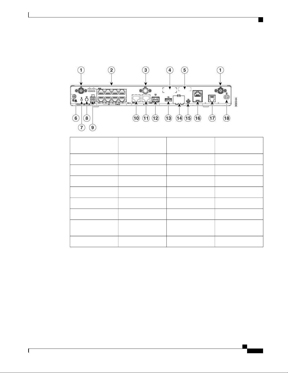
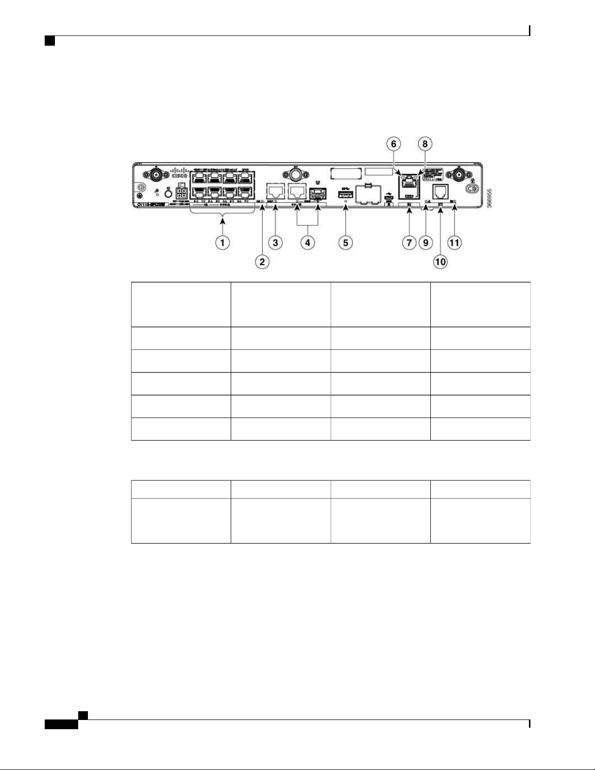
I/O View
Figure 2: Ci sco 1100 Series ISR - I/O Views
Label s on the Router
1
Labels on the Router
To obtain asoftwarelicense, you need aproduct authori zation key (PAK) and the uniquedevice identifier
(UDI) of thedevice where the l icense will beinstalled.
LTE Antennas – Mai n
and Diversity
LA N2
CLEI Label4GPS Connection3
Grounding6Serial Number5
Power Switch8Reset Button7
GE 0/0/1104-pin Power Connector9
GE 0/0/0 - SFP12GE 0/0/0 - RJ4511
uSIM * 214USB3.013
16LTE Provi sioning Port15
RJ45 / Micro USB
Console
Kensington Lock Slot18DSL17
Hardware Install ation Guide for the Ci sco 1100 Series Integrated Services Router
3
Page 14
For Additional Help Locating Labels on the Router
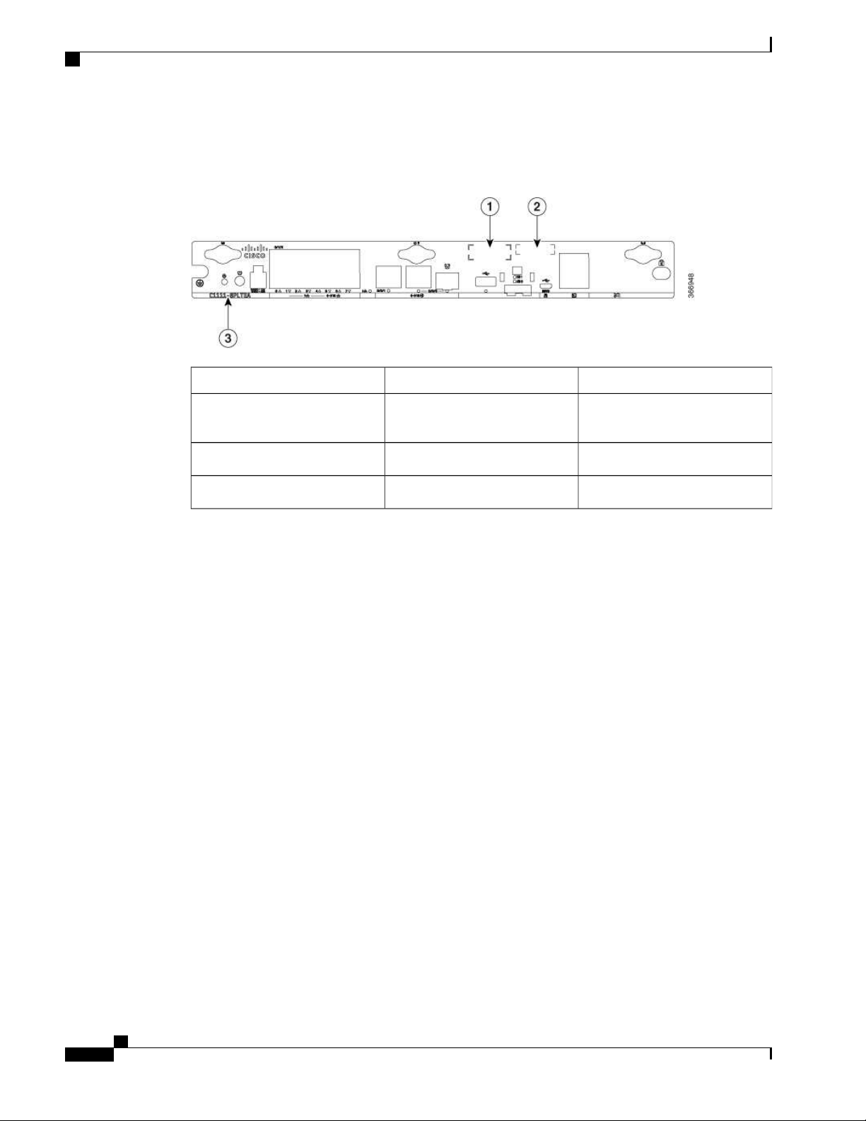
Figureshowsthelocation of the label s on theCisco 1100 SeriesISRs:
Figure 3: Labels on the Routers
Overview of Ci sco 1000 Series Integrated Services Routers
DescriptionNameSl . No
CLEI Number1
Serial Number2
For Additional Help Locating Labels on the Router
Use theCisco Product Identificati on (CPI) tool to find label s on therouter. Thetool provi des detailed
illustrati ons and descriptionsof where the labels are located on Cisco products. It includesthefollowing
features:
A search option that all ows browsi ng f or modelsby using a tree-structured product hierarchy
•
A search fiel d on the final results page that makes it easier to look up multiple products
•
End-of-sale productsclearly identified in results lists
•
Thetool streamlines theprocess of locating serial number label s and identifying products. Serial number
information expedites theentitlement processand is important for access to support services.
Hardware Features
Common LanguageEquipment
Identif ier (CLEI) number
Product Identification NumberPID Family Name3
This section describes the hardware features in therouters.
Interface Ports
TheCisco ISR C1100-8Pseries comeswith 8-Gigabit Ethernet LAN ports, and two WAN ports, with options
for oneLTE modem and oneWLAN interface.
Hardware Installation Guide for the Ci sco 1100 Seri es Integrated Services Router
4
Page 15
Overview of Cisco 1000 Series Integrated Services Routers
TheCisco ISR C1100-4Pseries comeswi th 4-Gigabit Ethernet LAN ports, and two WAN ports, with options
for oneLTE modem and oneWLAN interface.
Power-over-Ethernet (PoE)
TheC1100-8Pseries has 8 Ethernet LAN ports. Four of theEthernet LAN ports are PoE-capable, LAN ports
0-3. A total of 80W of PoE power is availableacrossthefour PoE-capable ports on the C1100-8P series.
TheC1100-4P serieshas 4 Ethernet LAN ports. Two of the Ethernet LAN ports arePoE-capabl e, LAN ports
0-1. A total of 60W of PoE power is availableacrossthetwo PoE-capable ports on theC1100-4P series.
Each indi vidual PoE-capable Ethernet LAN port is capable of PoE 802.3af or PoE+ 802.3at functionality.
Thetotal number of PoEand/or PoE+ devices that can beenabled on thePoEports at any onetimeis afunction
of the PoE power available from the external power supply. Softwarewill all ocate PoE power based on the
PoE power requested by thedevice on each port; and manage thetotal avail able power so as not to allocate
morepower than what is available.
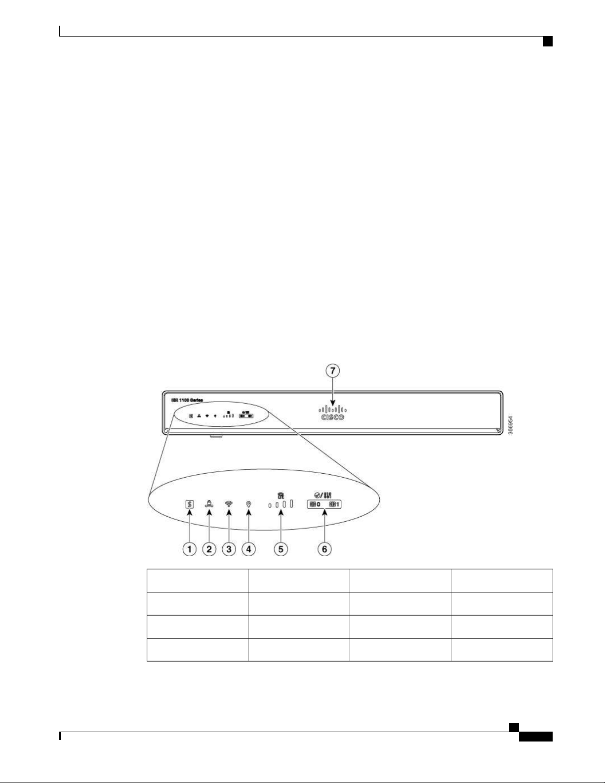
LED Indicators
Thefollowing figures and table summarizestheLED indicatorsthat arelocated in therouter bezel or chassis,
but not on the interface cards and modules.
Hardware Features
Figure 4: LED Indicators - Bezel Si de
VPN2Status1
GPS4WLAN3
LTE DATA/SIM6LTE RSSI/Mode5
Cisco Logo7
Hardware Install ation Guide for the Ci sco 1100 Series Integrated Services Router
5
Page 16
Hardware Features
Overview of Ci sco 1000 Series Integrated Services Routers
Figure 5: LED Indicators - I/O Side
1
(0,2,4,6 at the top and
1,3,5,7 at thebottom)
DATA L ED11
Table 1: LED Indicators - Description
BlueCisco Logo
PoE LED2GE WAN Ports: 0-7
GE0 LED4GE1 LED3
RJ-45 Console LED6USB LED5
MicroUSB ConsoleLED8USB Console7
DSL10CD LED9
LocationDescriptionLED ColorPort
Bezel sideBezel illuminated Cisco
logo. Indicates router
power is good.
Hardware Installation Guide for the Ci sco 1100 Seri es Integrated Services Router
6
Page 17

Overview of Cisco 1000 Series Integrated Services Routers
Hardware Features
LocationDescriptionLED ColorPort
(System Status)
Green and AmberSTATUS
Bezel side. All models.Steady Green - System
operates normally
Off—System is not out of
reset; or BIOS imageis
not loadable.
Blinking A mber —
BIOS/Rommon is
booting.
Steady Amber —
BIOS/Rommon has
completed booting, and
thesystem is at the
Rommon prompt or
booting the platform
software.
GreenVPN OK
Off—No tunnel .
Bezel side
Steady On— at least one
tunnel is up
Green and AmberLTE RSSI/Mode
No LEDs On—No
Bezel Side
Servi ce
1 LED On— RSSI is
under -100dBm
2 LEDsOn— Low RSSI,
-99dbm <> -90dBm
3 LEDs On— Medium
RSSI -89dBm <> -70dBm
4 LEDsOn— High RSSI,
> -69dBm
Green— LTE
Amber— 3G
Hardware Install ation Guide for the Ci sco 1100 Series Integrated Services Router
7
Page 18

Hardware Features
Overview of Ci sco 1000 Series Integrated Services Routers
LocationDescriptionLED ColorPort
Green and AmberGPS
Amber— Assisted GPS
Bezel Side
(Reserved for FutureUse)
Green— StandaloneGPS
Off— GPS not
confi gured
On— GPS configured
Blink— GPSAcquiring
Green and AmberLTE DATA/SI M
Bezel SideSingle LTE Modem (one
modem with SIM
swi tch-over capability)
Off— Modem not up or
modem up and no SIM
Amber Steady On—
Modem up,SIM installed
but not active.
Green Steady On—
Modem up,SIM installed
and active.
Ports, Non-PoE
Green Blink— LTE data
activity.
Green, Red, and AmberWLAN
Green— Normal
Bezel side
operating condition with
at least onewirelessclient
association.
Red—Ethernet link is not
operational or Ethernet
failure.
Amber—Software
upgradeis in progress.
GreenEthernet SwitchGE LAN
Off— No link
I/O side
Steady On— link
Blink— TXD/RXD data
Hardware Installation Guide for the Ci sco 1100 Seri es Integrated Services Router
8
Page 19

Overview of Cisco 1000 Series Integrated Services Routers
Hardware Features
LocationDescriptionLED ColorPort
Ports, with PoE
Green and AmberEthernet Switch GELA N
Off— No link, no device
I/O side
powered, PD denied
power, power delivery
fault PoE administratively
disabled.
Green Steady On— link;
if PoE device, power is
enabled.
Green Blink—
TXD/RXD data
Amber - PoE Fault
GreenGE WAN Ports
Off— No link
I/O side
Steady On— link
Blink— TXD/RXD data
GreenDSL CD
Off— Shut
I/O Side
Green Blink— Training,
or no shut and cable
disconnected.
Green Steady On—
Trained
GreenPoE OK
Green Steady On—
I/O Side
-53.5V PoEpower supply
connected and all
powered port operating
normall y.
Off — No -53.5V PoE
power supply connected
to router.
GreenDSL Data
Off— No Data Activity
I/O Side
Green Blink— TX/RX
Data
Hardware Install ation Guide for the Ci sco 1100 Series Integrated Services Router
9
Page 20

Slots and Interfaces
Overview of Ci sco 1000 Series Integrated Services Routers
LocationDescriptionLED ColorPort
Reset Button
Green and AmberConsole/AUX
GreenUSB Console
GreenUSB
Theactuation of the Reset button is only recognized during Rommon boot, that is, as therouter comes to the
Rommon prompt.
TheReset button does not require much force to be actuated. The Reset button should be actuated only with
a small implement such asthe ti p of a pen or apaper clip. When the Reset button is pressed at startup, the
system LED will turn green.
For more i nformation, see the "Reset Overview" section of the Cisco 1100 SeriesSoftwareConfiguration
Gui de.
Green On— Console
enabled.
Amber On— AUX
enabled.
Off— No USB device
discovered.
On— USB device
discovered.
discovered.
On: USB device
discovered.
I/O side
I/O side
I/O SideOff: No USB device
Slots and Interfaces
About Slots, Subslots, and Port Numbering
Cisco 1100 Series ISRs do not support physical and removable modules. It has only oneslot, that is, slot 0.
Sl ot 0 is themotherboard and not removable. It is reserved for integrated ports. The front panel GE ports (or
native interf aceports) al ways reside in slot 0 and bay 0. The ports arecalled Gigabitethernet 0/0/0 and
Gigabitethernet 0/0/1.
Each interfacetypehas its own 'bay', and port is a unique port of an interface type.
In most cases, therouter designatesi ts interfacesusi ng a 3-tuple notation that liststhe slot, bay, and port. The
3-tuple value is zero based. An example of a3-tuple is 0/1/2. This refersto slot 0, the second bay in slot 0
(thefirst bay is 0 so the second bay is1), and the third port in bay 1. See this section f or more examples.
Hardware Installation Guide for the Ci sco 1100 Seri es Integrated Services Router
10
Page 21
Overview of Cisco 1000 Series Integrated Services Routers
Table 2: Slot, Bay, and Port Numbering
Subslot/Bay Numbering
All interfaces are integrated interfaces. There is only oneBay, and the interface 'Type' is defined by a slot
number. In this example there is only one slot, 0, and each interface is a bay:
Bay 0 Ethernet WAN
Bay 1 Ethernet LAN (Switch)
Bay 2 LTE
Bay 3 DSL
Bay 4 WiFi
Chassis type: C1117-4PLTEEAWE
Slot Type State Insert time (ago)
--------- ------------------- --------------------- ----------------0 C1117-4PLTEEAWE ok 00:05:58
0/0 C1117-1x1GE ok 00:03:03
0/1 C1117-ES-4 ok 00:03:01
0/2 C1117-LTE ok 00:02:52
0/3 C1117-VADSL-A ok 00:01:56
0/4 ISR-AP1100AC-E ok 00:03:13
Specification
PortBaySlot3- Tuple Example
3rd2nd00/1/2
2nd1st00/0/1
Specification
Thefollowing table provide Cisco 1100 ISR specifi cation:
Tabl e 3: Cisco 1100 Series ISR Specification
SpecificationDescription
Physical Properties
Dimensions(H x W x D)
Non-LTE models:
H x W X D = 1.75 x 12.7 x 9.03 in. (42 x 323 x
230mm) (includes rubber feet)
LTE model s:
H x W X D = 1.75 x 12.7 x 9.6 in. (44 x 323 x 244
mm) (includes rubber feet)
5.5 Lbs. (2.5 kg) maximumWeight with AC PS (w/o modules)
AC Input Power
Hardware Install ation Guide for the Ci sco 1100 Series Integrated Services Router
11
Page 22

Specification
Overview of Ci sco 1000 Series Integrated Services Routers
SpecificationDescription
Universal 100 to 240 VACInput voltage
50-60 HzFrequency
Input current
Ports
USB port
Console port
10/100/1000 Gigabit Ethernet
PoE not enabled: 0.82A maximum
PoE enabled: 1.55A Maximum
90 A peak and less than 8 Armsper half cycl eSurgecurrent
One RJ-45: Separate consol e portMicro USB Port
USB 3.0 TypeA host port
USB devices supported:
USB flash memory
•
One USB 5-pin micro TypeB: Consolemanagement
connectivity
Two GE portsal located among RJ45 and SFP as:
One combo port with 10/100/1000RJ-45 Ethernet
port or SFP Ethernet port (labeled GE0/0/0)
One dedicated 10/100/1000RJ-45 Ethernet port
(labeled GE0/0/1)
32 (encrypted and non-encrypted VLANs)Wireless VLANs
2x2 .11ac Wave 2Wireless speci fications
4GBDef ault and maximum DRAM
4GBDef ault and maximum flash
InlinePoE
4 ports for -8P PIDs, 2 ports for -4P PIDs
802.3af-compliant PoE or 802.3at-compliant PoE+
Not Applicable - Fanless designAcoustic for Cisco 1100 SeriesISRs
Hardware Installation Guide for the Ci sco 1100 Seri es Integrated Services Router
12
Page 23
Overview of Cisco 1000 Series Integrated Services Routers
Specification
SpecificationDescription
Approvals and compliance
Emi ssion
•
47 CFR Part 15
•
CISPR 32 Edition 2
• ◦
EN 300 386 V1.6.1
◦
EN 55032:2012/ AC:2013
◦
EN 55032:2015
◦
EN61000-3-2 2014
◦
EN61000-3-3: 2013
◦
FCC §15.21
◦
ICES-003 ISSUE 6:2016
◦
KN 32: 2015
◦
V-2/2015.04
◦
V-3/2015.04
◦
TCVN 7189: 2009
◦
CNS13438: 2006
◦
IEC 60950-1
◦
EN 60950-1
◦
Table 4: Environmental Specifi cation
Environmental
SpecificationDescription
UL 60950-1
◦
CSA C22.2 No. 60950-1
◦
Immunity
•
CISPR24: 2010 + A1: 2015
◦
EN 300 386 V1.6.1
◦
EN55024: 2010 + A1: 2015
◦
KN35: 2015
◦
TCVN 7317: 2003
◦
Hardware Install ation Guide for the Ci sco 1100 Series Integrated Services Router
13
Page 24

Periodic Inspection and Cleaning
Overview of Ci sco 1000 Series Integrated Services Routers
SpecificationDescription
Operating humidity
Operating temperature
Transportation and Storage
Periodic Inspection and Cleaning
Periodic inspectionandcleani ngof theexternal surfaceof therouter isrecommended to minimizethenegative
impact of environmental dust or debris. The frequency of inspection and cleaning i s dependent upon the
severity of theenvironmental condi tions, but a minimum of every six months is recommended. Cleaning
involves vacuuming of router air intake and exhaust vents.
5 to 85% relative humidity
32 to 104°F (0 to 40°C) Sea L evel;
32 to 77°F (0°C to 25°C) at 10,000 ft
1.5°C derating per 1000 ft
0-6560 ft (0-2000 m)Altitudein China
0-10,000 ft (0-3050 m)Altitudein all other countries
-40 to 158°F (-40 to 70°C)Nonoperating temperature
5 to 95% relative humidity (noncondensi ng)Nonoperating humidity
0 to 15,000 ft (0 to 4570m)Nonoperating altitude
Note
Si tes with ambient temperatures consistentl y above 25°Cor 77°F and with potentiall y high levels of dust
or debris might requireperiodic preventativemaintenance cleaning.
Hardware Installation Guide for the Ci sco 1100 Seri es Integrated Services Router
14
Page 25

Preparing for Router Installation
Prepari ng for Router Installation, page 15
•
Preparing for Router Installation
Thisdocument provides pre-installati on information, such as recommendationsand requirementsthat should
bebefore installing your router. See the following sections to prepare for installation:
Safety Recommendations
CHA PTER
2
Warning
Warning
This warning symbol means danger. You are i n asituation that could cause bodily injury. Bef oreyou
work on any equipment, be aware of the hazards involved with electrical circuitry and be familiar with
standard practices for preventingaccidents. Usethestatement number provided at theend of eachwarning
to locate its translation in the translated saf ety warningsthat accompanied this device
SAVE THESE INSTRUCTIONS Statement 1071.Note
Ultimatedisposal of thi sproduct should behandled accordingto all national lawsandregulations. Statement
1040.
Safety With Electricity
Warning
Do not work on thesystem or connect or disconnect cables duringperiodsof lightning activity. Statement
1001
Hardware Install ation Guide for the Ci sco 1100 Series Integrated Services Router
15
Page 26

General Si te Requirements
Prepari ng for Router Installation
Warning
Warning
Warning
Warning
There is the danger of explosion if thebattery is replaced incorrectly. Replace the battery only with the
same or equival ent type recommended by the manufacturer. Dispose of used batteries according to the
manufacturer’s instructions. Statement 1015
Only trained and qualified personnel should beallowed to install or replace this equipment Statement
1030
Do not locate the antennanear overhead power lines or other electric light or power circuits, or where it
can comeinto contact with suchcircuits. When install ing theantenna, take extremecarenot to comeinto
contact with suchcircuits, asthey may causeserious injury or death. For proper installationandgrounding
of the antenna, please refer to national and local codes (for example, U.S.:NFPA 70, National Electri cal
Code, Article 810, Canada:Canadian Electrical Code, Section 54). Statement 1052
Do not usethisproduct near water; for example, near a bath tub, wash bowl, kitchen sink or laundry tub,
in awet basement, or near a swimming pool. Statement 1035
Installation of theequipment must comply with local and national el ectrical codes. Statement 1074Warning
Preventing Electrostatic Discharge Damage
Electrostatic discharge (ESD) can damageequipment andimpair electrical circui try. It can occur if electronic
printed circuit cardsare improperly handled and can cause complete or intermittent failures. A lways follow
ESD prevention procedures when removing and replacing modules:
Ensurethat the router chassis is electrically connected to ground.
•
Wear an ESD-preventive wrist strap, ensuring that it makes good skin contact. Connect theclip to an
•
unpainted surfaceof the chassi s frame to channel unwanted ESD voltages safely to ground. To guard
against ESD damageand shocks, the wrist strap and cord must operate effectively.
If no wrist strap is available, ground yourself by touching a metal part of the chassi s.
•
Caution
For thesafety of your equipment, periodically check the resistance value of theanti-stati c strap. It should
bebetween 1 and 10 megohms (Mohm).
General Site Requirements
This sectiondescribes therequirementsyour site must meet for safe installationandoperation of your router.
Ensurethat thesite is properly prepared beforebeginning installation. I f you are experi enci ng shutdownsor
Hardware Installation Guide for the Ci sco 1100 Seri es Integrated Services Router
16
Page 27

Prepari ng for Router Installation
unusuall y hi gh errorswi th your existingequipment, thissection can also help you i solate thecause of fail ures
and prevent future problems.
Rack Requirements
Warning
Warning
This product relieson thebuilding’sinstallation for short-circuit (overcurrent) protection. Ensure that the
protective device is rated not greater than: 20A. Statement 1005
To prevent the system from overheating, do not operate it in an areathat exceeds themaximum
recommended ambient temperatureof: 40 degrees C. Statement 1047
Site Selection Guidelines
TheCisco 1100 SeriesISRs require specific environmental operating conditions. Temperature, humidity,
altitude, and vibration can affect the performance and reli ability of therouter. Thefoll owing sections provide
specific information to help you plan for the proper operating environment.
TheCisco 1100 SeriesISRs are desi gned to meet the industry EM C, safety, and environmental standards
described in the Regulatory Complianceand Safety Information for theCisco 1100 Series I SRsdocument.
Rack Requirements
Cisco 1100 Series ISRs require brackets for use with a19-inch rack.
Thefollowing information can help you plan your equipment rack configurati on:
Allow clearance around the rack for maintenance.
•
Allow at least onerack unit of vertical space between routers; moreclearance i s requi red when stacking
•
mul tipleCisco 1100 Series ISRs. Provideadequate heat removal mechanism to keep the surrounding
air temperature well within the speci fied operating temperaturecondition.
More spacing may be required depending on the installation environment.Note
Enclosed racks must have adequate ventilation. Ensurethat the rack is not congested, because each
•
router generates heat. An enclosed rack should have louvered sides and af an to providecooling air.
Heat generated by equipment near thebottom of therack can bedrawn upward into theintake ports of
theequipment above it.
When mounting achassis in an open rack, ensurethat therack framedoesnot block theintakeor exhaust
•
ports. If the chassis is instal led on slides, check the position of the chassis when it is seated in the rack.
Router Environmental Requirements
Cisco1100 Series I SRscan be placedon a desktop, i nstall ed in arack, or mounted on a wall . The location of
your router and thelayout of your equipment rack or wiri ng room are extremely important considerationsf or
proper operati on. Equipment placed too close together, inadequateventilati on, and inaccessible panels can
Hardware Install ation Guide for the Ci sco 1100 Series Integrated Services Router
17
Page 28

Power Guidelines and Requi rements
causemalfunctionsand shutdowns, and can makemaintenance difficult. Plan for accessto bothfront and rear
panelsof the router.
When planning your site layout and equipment locations, refer to the General Site Requirements , section. If
youarecurrently experiencing shutdownsor an unusually high number of errorswithyour existingequipment,
theseprecautionsandrecommendati onsmay help youi solatethecauseof failureand prevent future problems.
Ensurethat the room where your router operates has adequate air circulati on. Electri cal equipment
•
generates heat. Without adequateair circulation, ambient air temperature may not cool equipment to
acceptable operati ng temperatures.
Alwaysfollow ESD-preventionproceduresdescribed i n thePreventingElectrostatic DischargeDamage
•
to avoid damageto equipment. Damage from static dischargecan cause i mmediate or intermittent
equipment fail ure.
Baffles can help to isolate exhaust air from intake air, which also helps to draw cooling air through the
•
chassis. The best placement of the baffles depends on the airfl ow patternsin the rack, which can be
found by experi menting with different confi gurati ons.
When equipment instal led in arack (particularly in an enclosed rack) fai ls, try operating theequipment
•
by itself, if possible. Power off other equipment in the rack (and in adjacent racks) to all ow the router
under test a maximum of cooling air and clean power.
Prepari ng for Router Installation
Power Guidelines and Requirements
Check the power at your site to ensurethat you arereceiving “clean” power (free of spikes and noise). Install
a power conditioner if necessary.
Power Guidelines and Requirementslists power requirements for theCisco 1100 SeriesISRs.
Table 5: Power Requirements for Cisco 1100 Series ISRs
(PWR-66W-AC-V2)
(PWR-125W-AC)
(PWR-115W-AC)
Network Cabling Specifications
Thefollowing sections descri bethecables needed to instal l your Cisco 1100 Series I SR in the following
secti ons:
Output RatedInput RatedPower Source
12 VDC, 5.5A100-240V, 2A66W AC Power Adapter
12VDC, 3.5A; -53.5Vdc, 1.55A100-240 VAC, 2A, 50-60 Hz125W AC Power Adapter
12V, 4.6A, -53.5V 1.12A100-240VAC, 2A, 50-60 Hz115W AC Power Adapter
Hardware Installation Guide for the Ci sco 1100 Seri es Integrated Services Router
18
Page 29

Prepari ng for Router Installation
Console Port Connections
Therouter has both EIA/TIA-232 asynchronous (RJ-45) and USB 5-pin micro TypeB, 2.0 compliant serial
console ports. The consoleports do not haveany hardwarefl ow control. Shielded USB cables wi th properly
terminated shieldsare recommended.
EIA/TIA-232
Dependi ng on thecable and the adapter used, this port appearsas a DTE or DCE deviceat theend of the
cable. Only one port can beused at thesame time.
Thedefault parameters for theconsole port are 9600 baud, 8 data bits, 1 stop bit, and no parity. The console
port doesnot support hardwareflow control. For detai led information about installingaconsoleterminal, see
theConnecting to a Console Terminal or Modem secti on.
For cable and port pinouts, see the Cisco Modular Access Router Cable Specificationsdocument located on
Cisco.com.
USB Serial Console
TheUSB serial console port connects directl y to the USB connector of a PC using a USB TypeA to 5-pin
micro USB Type-B cable. TheUSB Console supports full speed (12Mb/s) operation. The consol e port does
not support hardware flow control.
Network Cabling Specifications
Alwaysuse shi elded USB cables with a properly terminated shield.Note
Thedefault parameters for theconsole port are 9600 baud, 8 data bits, no parity, and 1 stop bit. For detailed
information about instal ling a console terminal, see the Connecting to a ConsoleTerminal or Modem section
on page 3-19.
For operation with aMicrosoft WindowsOSversion older than Wi ndows7, theCiscoWindowsUSB Console
Driver must be instal led on any PC connected to the console port. I f thedriver is not installed, promptsguide
you through a simple installation process.
TheCisco Windows USB ConsoleDriver allows pluggi ng and unplugging theUSB cabl e from the console
port without affecting Windows HyperTerminal operations. No special driversare needed for Mac OS X or
Linux.
Onl y oneconsole port can beacti ve at atime. When a cableis plugged into the USB console port, theRJ-45
port becomesi nactive. Conversely, when theUSB cableisremoved from theUSB port, theRJ-45port becomes
active.
Baud ratesfor the USB console port are 1200, 2400, 4800, 9600, 19200, 38400, 57600, and 115200 bps.
Note
4- pin microUSB Type-B connectorsare easily confused with 5-pin micro USB Type-B connectors. Only
the5-pin mi cro USB Type-B is supported.
USB Console OS Compatibility
Windows10, Windows8, Windows 7, Wi ndows2000, Window XP 32 bit, Windows Vista 32 bit
•
Mac OS X version 10.5.4
•
Hardware Install ation Guide for the Ci sco 1100 Series Integrated Services Router
19
Page 30

Required Tools and Equipment for Installation and Mai ntenance
Redhat / Fedora Core 10 with kernel 2.6.27.5-117
•
Ubuntu 8.10 with kernel 2.6.27-11
•
Debian 5.0 with kernel 2.6
•
Suse 11.1 with kernel 2.6.27.7-9
•
Console Port Considerations
Therouter includes an asynchronous serial console port. Theconsole ports provide accessto therouter using
a console termi nal connected to the consol e port. This section discusses important cabling information to
consider beforeconnecting the router to aconsole terminal or modem.
Console terminals send data at speedsslower than modems do; theref ore, the consol e port is ideally suited
for use with console terminals.
Preparing for Network Connections
When setting up your router, consi der distancelimitations and potential electromagnetic interference (EMI)
as defined by theappl icable local and international regulations.
Network connection considerationsare provided for:
Seethefollowing onlinedocument for moreinformation about network connections and interfaces:
Prepari ng for Router Installation
Cisco Modul ar Access Router Cable Speci fi cations
•
Ethernet Connections
TheIEEE has established Ethernet as standard IEEE 802.3. Therouterssupport the f ollowing Ethernet
implementations:
• 1000BASE-T—1000Mb/s full-duplex transmissi on over aCategory 5 or better unshielded twisted-pair
(UTP) cable. Supports the Ethernet maximum length of 328 feet (100 meters).
• 100BASE-T—100 Mb/sfull-duplex transmission over aCategory 5 or better unshielded twisted-pair
(UTP) cable. Supports the Ethernet maximum length of 328 feet (100 meters).
• 10BASE-T—10 Mb/sfull-dupl ex transmissionover aCategory 5or better unshielded twisted-pair (UTP)
cable. SupportstheEthernet maximum l ength of 328 feet (100 meters).
SeetheCisco Modular Access Router Cable Specificationsdocument at Cisco.com for information about
Ethernet cables, connectors, and pinouts.
Required Tools and Equipment for Installation and Maintenance
You need the following tools and equipment to install and upgradethe router and its components:
ESD-preventive cord and wrist strap
•
Number 2 Philli psscrewdriver
•
Philli psscrewdrivers: small, 3/16-in. (4 to 5 mm) and medium, 1/4-in. (6 to 7 mm)
•
Hardware Installation Guide for the Ci sco 1100 Seri es Integrated Services Router
20
Page 31

Prepari ng for Router Installation
To install or removemodules
◦
To remove the cover, if you are upgrading memory or other components
◦
Screws that fi t your rack
•
Wire crimper
•
Wire for connecti ng the chassi s to an earth ground:
•
AWG 14 (2 mm 2 ) or larger wire for NEC-compl iant chassis grounding
◦
For NEC-compl iant grounding, an appropriateuser-supplied ring terminal, with an inner diameter of
•
1/4 in. (5 to 7 mm)
Installation Checklist
Thesample installation checklist lists items and procedures for installi ng a new router. Make acopy of this
checklist and mark the entries when completed. Include a copy of the checklist for each router in your site
log (described in the next section, Creating a SiteLog).
Installation Checklist
Table 6: Checklist
Installation checklist copied
Background informati on placedin
Si te Log
Si te power voltages verifi ed
Installation site power check
completed
Required tools avai lable
Additional equipment available
Router received
Router quick start guide received
Regulatory Complianceand Safety
Information for the Cisco 1100
Series ISRs document received
DateVerified ByTask
Product registration card received
Cisco.com contact information
label received
Hardware Install ation Guide for the Ci sco 1100 Series Integrated Services Router
21
Page 32

Creating a Si te Log
Prepari ng for Router Installation
DateVerified ByTask
Chassis componentsverifi ed
Initial electrical connections
established
ASCI I termi nal (for local
confi gurati on) or modem (for
remoteconfiguration) available
Si gnal distance limits verified
Startup sequencesteps completed
Initial operati on verified
Softwareimage verified
Creating a Site Log
TheSite Log provides a record of all actionsrelated to the router. K eep it in an accessible place near the
chassis where anyonewho performstaskshas accessto i t. Use the instal lation checklist to verify steps in the
installation and maintenance of therouter. Site Log entriesmight include the following i nformation:
• Installation progress—Make a copy of the instal lation checklist and insert it into the site log. Make
entriesas each procedureis completed.
• Upgrade and maintenance procedures—Usethesite log as a record of ongoing router maintenance and
expansion history. A site log might include thefoll owing events:
Inspect all items for shipping damage. If anything appearsto bedamaged or if you encounter problems
installing or conf iguring your router, contact customer service. Warranty, service, and support information is
in the quick start guidethat shipped with your router, or in the Preface of this guide. See the Obtaining
Documentation and Submitting a Service Request section.
Removal or replacement of PoE daughter card
◦
Configuration changes
◦
Maintenance schedules and requirements
◦
Maintenance procedures performed
◦
Intermittent problems
◦
Comments and notes
◦
Hardware Installation Guide for the Ci sco 1100 Seri es Integrated Services Router
22
Page 33

Installing and Connecting the Router
Installi ng and Connecting the Router, page 23
•
Installing and Connecting the Router
Thisdocument descri bes how to install and connect the Cisco 1100Series IntegratedServicesRouters(ISRs)
to LAN and WAN networks. The following sections providetechni cal details.
Safety Warnings
CHA PTER
3
Warning
Read theinstallation instructi ons beforeusing, installing or connecting thesystem to thepower source.
Statement 1004
What You Need to Know
CLI Console Access
Use theUSB or RJ-45 consoleport on therouter to access theCisco I nternet Operating System (IOS-XE)
command line interface(CLI) on therouter and perform configuration tasks. A terminal emulation program
is requiredto establishcommunicationbetweentherouter and aPC. SeetheConnectingto aConsoleTerminal
or Modem for instructions.
Note
A Microsoft WindowsUSB driver must beinstalled beforeyou establish physical connectivity between
therouter and thePC.
Sl ot and Port Numbers
Theroutershavebuilt in portsand slots. See theAbout Slotsand Interfacessectionfor slot andport numbering.
Hardware Install ation Guide for the Ci sco 1100 Series Integrated Services Router
23
Page 34

Before You Begin
Software Li censes
To use all thefeatures on therouter, you must purchase a softwarepackage.
SeetheLicensing section of the SoftwareConfiguration Guidefor the Cisco 1100 SeriesISRs for more
information.
Before You Begin
Beforeinstalling and connecting a Cisco Integrated Services Router, read the safety warningsand gather the
following tools and equipment. For more information about therequired tools and equipment.
Installi ng and Connecting the Router
Note
For moreinformationoncable specifications, see theCisco Modular AccessRouter Cable Specifications
document on Cisco.com.
Unpacking the Router
Do not unpack therouter until you areready to instal l it. If thefinal installati onsite will not beready for some
time, keep the chassi s in its shipping container to prevent accidental damage. When you are ready to install
therouter, proceed with unpacking it.
Therouter, accessory kit, publications, and any opti onal equipment you ordered may be shippedin morethan
one container. When you unpack thecontai ners, check the packing list to ensure that you received all of the
items on the list.
Installing the Router
If you need to install PoE daughter card, you can install them beforeyou instal l the router. Ideally, thePoE
daughter card should be purchased pre-installed.
There are two methods of instal ling the router:
Caution
Toprevent damageto the chassis, never attempt to lift or tilt the chassis by holding it by the plastic panel
on the front. Always hold thechassis by thesides of themetal body.
Installing a Cisco 1100 Series ISR
This section descri bes how to install theCisco 1100 Series ISR. These routerscan bei nstalled on atabletop
or other flat horizontal surfacemounted on a wall or DIN rail.
Warning
Hardware Installation Guide for the Ci sco 1100 Seri es Integrated Services Router
24
Radiofrequency Exposure- To maintain compliance, installations should ensurea separati on distance of
at least 20 cm.
Page 35

Installing and Connecting the Router
Installi ng the Router
Note
More clearancei s required when stacking multiple Cisco 1100 ISRs or having heat removal capability to
maintai n the surrounding air temperatureto stay within the speci fied operating condition.
Attaching the Chassis
Thetasksthat you perform for attaching therouter chassis to thewall or for mounting it in arack are based
on the specific model of theCisco 1100 Series Integrated Service Router.
Therecommended clearancewhen hori zontall y mounted is 1.5 inches on both sides for clearance and 1.75
incheson top. I/O side clearanceis needed as it is required to access thecable connections. Clearance is not
required on thebackside(opposite sidefrom I/O face) unless DIN rail mounting is required. Clearance is
required to attach and mount theDIN rail bracket.
Mounting on the Wall
TheCisco 1100 SeriesISRshave mounting key-hole slots on the bottom of thechassisfor mounting the unit
on a wall or other vertical surface, as shown in the figurebelow.
Hardware Install ation Guide for the Ci sco 1100 Series Integrated Services Router
25
Page 36

Installing the Router
Installi ng and Connecting the Router
Note
Theunit must not be mounted with theoutput portsfacing downwards. You must mount the unit with the
cables going si deways.
Figure 6: Mounting on the Wall
Key-holeslots1
Note
To attach to a wall stud, each bracket requires onenumber-10 wood screws (round- or pan-head) with
number-10washers, or twonumber-10 washer-head screws. Thescrewsmust belong enough to penetrate
at least 1.5 inches (38.1 mm) into the supporting wood or metal wall stud.
Note
For hollow-wall mounting, each bracket requirestwo wall anchorswith washers. Wall anchorsand washers
must besizenumber 10. Route the cablesso that they do not put a strain on the connectors or mounting
hardware.
Hardware Installation Guide for the Ci sco 1100 Seri es Integrated Services Router
26
Page 37

Installing and Connecting the Router
When choosing a location for wall-mounting the router, consi der cable limitationsand wall structure.Note
Thefigure below shows the orientation for wall mounting of the router.
Figure 7: Wall -Mount Orientation
Installi ng the Router
Key-hole slots1
Hardware Install ation Guide for the Ci sco 1100 Series Integrated Services Router
27
Page 38

Installing the Router
Attaching DIN Rail Brackets
Step 1: Attach the brackets to the router chassis as shown in the figurebelow, usi ng the PHMS screws and
theplastic spacers provided for each bracket.
Figure 8: DIN Rail Bracket Installation
Installi ng and Connecting the Router
Screws1
DIN Rail Brackets2
Do not over-torquethescrews. The recommended torque is 8 to 10 inch-lbf (.9 to 1.1 N-m).Note
Your chassisinstallation must allow unrestricted airfl ow for chassis cooling.Note
Step 2: Attach the router to the wall using the key-hole slots.
Hardware Installation Guide for the Ci sco 1100 Seri es Integrated Services Router
28
Page 39

Installing and Connecting the Router
Thefigure below displays the orientation of theDIN rail bracket.
Figure 9: DIN Rail Bracket Orientation
Installi ng the Router
Thefigure below displays the DIN rail orientation and mount.
Figure 10: DIN Rail Orientation and Mount
Hardware Install ation Guide for the Ci sco 1100 Series Integrated Services Router
29
Page 40

Installing the Router
Af ter the router is install ed, you must connect the chassis to arel iable earth ground. For thechassis ground
connection procedures, see the“Chassis Grounding” section.
Mounting the Router in a Rack
1
Attach the brackets to the router chassis (towards the left or right) as shown in figure below.
Figure 11: Bracket Installation for Left-Hand-Mounting
Installi ng and Connecting the Router
Warning
Warning
In the similar manner, you can install thebracket on theright-hand for mounting.Note
2
Use thescrews provided with the rack to i nstall thechassis in the rack.
To prevent bodily injury when mountingor servicing thisunit in a rack, you must takespecial precautions
to ensure that thesystem remains stable. Thefollowing guideli nes areprovided to ensureyour safety:
This unit should be mounted at thebottom of therack if it is the only unit in the rack.
•
When mounting this unit in apartially filled rack, load the rack from the bottom to the top with the
•
heaviest component at thebottom of therack.
If therack is provided with stabili zing devices, i nstall thestabilizers before mounting or servicing
•
theunit in the rack. Statement 1006
Warning To prevent airflow restriction, all ow clearance around the ventilation openings to beat least:
1.75 in. (4.4 cm). Statement 1076
Af ter the router is install ed, you must connect the chassis to arel iable earth ground. For thechassis ground
connection procedures, see the“Chassis Grounding” section.
Hardware Installation Guide for the Ci sco 1100 Seri es Integrated Services Router
30
Page 41

Installing and Connecting the Router
Setting the Chassis on a Desktop
You can place therouter on adesktop, bench top, or shelf.
Af ter the router is installed, you must connect the chassis to a reliable earth ground. For the chassi s ground
connection procedures, see theChassis Groundi ng section.
Chassis Grounding
Installi ng the Router
Warning
This equipment must begrounded. Never defeat the ground conductor or operate theequipment in the
absenceof asuitabl y installed ground conductor. Contact the appropri ate electrical inspection authority
or an electrician if you areuncertai n that suitable grounding is avail able. Statement 1024
You must connect the chassisto a reliableearth ground; the ground wire must beinstalled in accordance with
local electrical safety standards.
For grounding, use size 14 AWG copper wire and the ground lug (which are not a part of the accessory
•
kit).
Use theUNC 6-32 screws, which have a length of about 0.25 inches
•
Use 14AWG wire for installation.Note
To install theground connection for your router, perform thefollowing steps:
1
Strip one end of the ground wire to the length required for the ground lug or terminal.
• For theground lug—approximatel y 0.75 inch (20 mm)
• For user-provided ring terminal—as required
2 Crimp theground wire to the ground lug or ring terminal, usi ng a crimp tool of theappropriate size.
Hardware Install ation Guide for the Ci sco 1100 Series Integrated Services Router
31
Page 42

Connecting to a Console Terminal or Modem
3 Attach the ground lug or ring terminal to thechassis as shown in Figure. For aground lug, one of the
screws provided. Tighten the screw to a torqueof 8 to 10 in-lb (0.9 to 1.1 N-m).
Figure 12: Chassis Ground Connection on the Router
Installi ng and Connecting the Router
Connecting to a Console Terminal or Modem
Therouter hasasynchronousserial ports. These portsprovideadministrativeaccessto therouter either locall y
(with aconsole terminal or aPC) or remotely (with a modem).To configure therouter through theCisco IOS
CLI, you must establish a connection between therouter console port and ei ther a terminal or aPC.
Use thefollowing cablesand adapters to establish a local or remote connection.
Screw (UNC 6-32)1
Ground Lug2
Hardware Installation Guide for the Ci sco 1100 Seri es Integrated Services Router
32
Page 43

Installing and Connecting the Router
Table 7: Local and Remote Connections
Type
Connecting to a Console Terminal or Modem
SectionCabl ePort
Serial
(RJ-45)
Serial
(USB)
RJ-45
Micro
USB
Connecting to the Serial Port with Microsoft Windows, on page33EIA
Type-B
to USB
Type-A
Connecting to the Serial Port with Microsoft Windows
Note
Install the USB device driver before establishing a physical connection between the router and the PC
using the USB Console cable pluggedinto the USB serial port, otherwise theconnectionwill fail. See the
“Installi ng the Cisco Microsoft WindowsUSB DeviceDriver” section.
1
Connect theend of theconsolecable with theRJ-45 connector to thelight blueconsole port on the router.
2 or
Connect a USB 5-pi n mi cro USB Type-B to the USB console port. I f you are using theUSB serial port
for the first time on a Windows-based PC, install theUSB driver now according to the instructionsin the
following sections.
• “Installi ng the Cisco M icrosoft WindowsXP USB Driver” section
• “Installi ng the Cisco M icrosoft Windows2000 USB Driver” section
• “Installi ng the Cisco M icrosoft WindowsVistaUSB Driver” section
"Installing the Cisco Microsoft Windows 8 and Windows 10 USB Driver" section
•
Note
You cannot use the USB port and the EIA port concurrently. When theUSB port is used it takes priority
over the RJ-45 EIA port.
3 Connect theend of the cable with the DB-9 connector (or USB Type-A) to the terminal or PC. If your
terminal or PC has a console port that does not accommodate a DB-9 connector, you must providean
appropriate adapter for that port.
4 To communi cate with therouter, start aterminal emul ator applicati on. Thissoftware should be configured
with thef ollowing parameters:
9600 baud
•
8 data bits
•
Hardware Install ation Guide for the Ci sco 1100 Series Integrated Services Router
33
Page 44

Connecting to a Console Terminal or Modem
no parity
•
1 stop bit
•
no flow control
•
Connecting to the Console Port with Mac OS X
This procedure describes how to connect a Mac OS X system USB port to theconsole using the built in OS
X Terminal util ity.
Installi ng and Connecting the Router
Step 1
Step 2
Step 3
Step 4
Use theFinder to go to Appl ications> Utilities> Terminal.
Connect theOSX USB port to therouter.
Enter thefollowing commandsto find the OSX USB port number
Example:
macbook:user$ cd /dev
macbook:user$ ls -ltr /dev/*usb*
crw-rw-rw- 1 root wheel 9, 66 Apr 1 16:46 tty.usbmodem1a21 DT-macbook:dev user$
Connect to theUSB port with the following command followed by the router USB port speed
Example:
macbook:user$ screen /dev/tty.usbmodem1a21 9600
To di sconnect the OS X USB console fr om the Terminal window
Enter Ctrl-a followed by Ctrl-\
Connecting to the Console Port with Linux
Thisprocedureshowshow to connect a Linux system USB port to the consoleusing thebuilt in Linux Terminal
utili ty.
Step 1
Step 2
Step 3
Step 4
34
Open the Linux Terminal window.
Connect theLinux USB port to the router.
Enter thefollowing commandsto find the Linux USB port number
Example:
root@usb-suse# cd /dev
root@usb-suse /dev# ls -ltr *ACM*
crw-r--r-- 1 root root 188, 0 Jan 14 18:02 ttyACM0
root@usb-suse /dev#
Connect to theUSB port with the following command followed by the router USB port speed
Hardware Installation Guide for the Ci sco 1100 Seri es Integrated Services Router
Page 45

Installing and Connecting the Router
Installi ng the Ci sco Microsoft Windows USB Device Driver
Example:
root@usb-suse /dev# screen /dev/ttyACM0 9600
To di sconnect the Linux USB console f rom the Ter mi nal window
Enter Ctrl-a followed by : then quit
Installing the Cisco Microsoft Windows USB Device Driver
A USB device driver must beinstal led thefirst timeaMicrosoft Windows-based PC isconnected to theUSB
serial port on the router.
This section containsthefollowing topics:
Installing the Cisco Microsoft Windows XP USB Driver
Step 1
Step 2
Step 3
Step 4
Step 5
Step 6
Step 7
This procedure shows how to install theMicrosoft Windows XP USB driver.
Beforeyou begin, download the appropri ate driver for your router model from theCisco SoftwareDownload
si te, USB Console Softwarecategory:
Unzi p the file Cisco_usbconsole_dri ver_X_X.zip (where X i s a revi sion number).
If using 32-bit Windows XP double-cl ick thefile setup.exe from the Windows_32 folder, or if using 64-bit Windows
XP double-click the fil e setup(x64).exe from the Windows_64 folder.
TheCisco Virtual Com Install Shield Wizard begins. Cl ick Next.
TheReady to Install theProgram window appears, Click Install.
TheInstallShield Wizard Completed window appears. Cl ick Finish.
Connect theUSB cable to the PC and router USB consol e. The LED of the USB consoleport turnsgreen, and within a
few momentstheFound New HardwareWizard appears.Follow theinstructionsto complete theinstallati onof thedriver.
TheUSB console is now ready for use.
http://www.cisco.com/cisco/sof tware/navigator.html
Hardware Install ation Guide for the Ci sco 1100 Series Integrated Services Router
35
Page 46

Installing the Ci sco Microsoft Windows USB Device Dri ver
Installing the Cisco Microsoft Windows 2000 USB Driver
This procedure shows how to install theMicrosoft Windows 2000 USB driver.
Installi ng and Connecting the Router
Step 1
Step 2
Step 3
Step 4
Step 5
Step 6
Step 7
Obtain thefile Cisco_usbconsole_driver.zip from the Cisco.com web site and unzip it.
Double-cl ick the fil e setup.exe.
TheCisco Virtual Com Install Shield Wizard begins. Cl ick Next.
TheReady to Install theProgram window appears, Click Install.
TheInstallShiel d Wizard Completed window appears. Click Finish.
Connect theUSB cable to the PC and router USB console ports. The LED for the USB console port turns green, and
within afew momentsa series of Found New Hardware Wizard windows appear. Follow theinstructionsto complete
theinstallation of thedriver.
TheUSB console is now ready for use.
Installing the Cisco Microsoft Windows Vista USB Driver
This procedure shows how to install theMicrosoft Windows Vista USB driver.
Step 1
Step 2
Step 3
Step 4
Obtain thefile Cisco_usbconsole_driver.zip from the Cisco.com web site and unzip it.
If using 32-bit Windows Vista double-click the file setup.exefrom the Windows_32 folder, or if using 64-bit Windows
Vistadouble-cli ck the file setup(x64).exe from the Windows_64 folder.
TheCisco Virtual Com Install Shield Wizard begins. Cl ick Next.
TheReady to Install theProgram window appears, Click Install.
Note
If aUser Account Control warningappears,click “Allow - I trust thisprogram...” to proceed.
Step 5
Step 6
Step 7
TheInstallShiel d Wizard Completed window appears. Click Finish.
Connect theUSB cable to the PC and router USB console ports. The LED for the USB console port turns green, and
within afew momentsa pop up window stating “Installing device driver software” appears. Fol low the instructionsto
complete theinstal lation of thedriver.
TheUSB console is now ready for use.
Installing the Cisco Microsoft Windows 8/Windows 10 USB Driver
This procedure shows how to install theMicrosoft Windows 8/Windows10 USB driver.
Step 1
36
Obtain theCisco USB console driver file from the Cisco.com web site and unzip it.
You can download thedriver filefromtheCisco.comsitef or downloading therouter software.Note
Hardware Installation Guide for the Ci sco 1100 Seri es Integrated Services Router
Page 47

Installing and Connecting the Router
Uninstal li ng the Cisco Microsoft Windows USB Driver
Step 2
Step 3
Step 4
Step 5
Step 6
Step 7
If using 32-bit Windows 8 or Windows 10, double-cli ck the setup.exe file in the Windows_32 folder. If using 64-bit
WindowsVista or Windows8 or Windows 10, double-cli ck the setup(x64).exe file in the Windows_64 folder.
TheCisco Virtual Com Install Shield Wizard begins. Cl ick Next.
TheReady to Install theProgram window appears, Click Install.
If aUser Account Control warningappears, click Allow - I trust this program toproceed.Note
TheInstallShield Wizard Completed window appears. Cl ick Finish.
Connect theUSB cable to the PC and router USB consol e ports. The LED for the USB console port turns green, and
within afew momentsa series of Found New Hardware Wizard windowsappear. Follow the i nstructionsto complete
theinstallation of thedriver.
TheUSB console is now ready for use.
Uninstalling the Cisco Microsoft Windows USB Driver
This section provides instructionsfor how to uninstall theCisco Microsoft Windows USB devicedriver.
Uninstalling theCisco Microsoft WindowsXP and 2000 USB Driver, on page 37
•
Uninstalling theCisco Microsoft WindowsVistaUSB Driver, on page 38
•
Uninstalling the Cisco Microsoft Windows XP and 2000 USB Driver
Thisprocedure showsyou how touni nstall boththeMicrosoft WindowsXP and 2000USB driver. Thedriver
can beremoved using the Windows Add RemoveProgramsutility or thesetup.exe program.
Usi ng the Add Remove Programs util ity
Disconnect the router console terminal before uninstal ling the driver.
1
Click Start > Control Panel > Add or RemovePrograms.
2
Scroll to Cisco Virtual Com and click Remove.
3
When theProgram Maintenance window appears, select theRemove radio button. Click Next.
Usi ng the Setup.exe pr ogr am
Disconnect the router console terminal bef oreuni nstalling thedriver.Note
1
Run thesetup.exe for Windows 32-bit or setup(x64).exe for Windows-64bit. Click Next.
2
TheInstallShi eld Wizard for Cisco Virtual Com appears. Click Next.
3 When theProgram Maintenance window appears, select theRemove radio button. Click Next.
4
When theRemove theProgram window appears, click Remove.
5 When theInstallShield Wizard Completed window appears click Finish.
Hardware Install ation Guide for the Ci sco 1100 Series Integrated Services Router
37
Page 48

Connecting WAN and LAN Interfaces
Uninstalling the Cisco Microsoft Windows Vista USB Driver
This procedure shows you how to uninstal l the Microsoft Windows Vista USB driver.
Disconnect the router console terminal bef oreuni nstalling the driver.Note
Installi ng and Connecting the Router
Step 1
Step 2
Step 3
Step 4
Step 5
Run the setup.exe for Windows 32-bit or setup(x64).exe for Windows-64bit. Click Next.
TheInstallShiel d Wizard for Cisco Virtual Com appears. Click Next.
When theProgram Maintenance window appears, select the Removeradio button. Cli ck Next.
When theRemovetheProgram window appears, click Remove.
Note
If aUser Account Control warningappears,click “Allow - I trust thisprogram...” to proceed.
When theInstallShield Wizard Completed window appears click Finish.
Connecting WAN and LAN Interfaces
This section describes how to connect WA N and LAN interface cables. It covers the following topics:
Warning
Warning
Do not work on thesystem or connect or disconnect cables duringperiodsof lightning activity. Statement
1001
Class1 laser product. Statement 1008Warning
Hazardous network voltagesare present in WAN ports regardl ess of whether power to the unit is OFF or
ON. To avoid electric shock, use caution when working near WAN ports. When detaching cables, detach
theend away from the unit first. Statement 1026
Caution
To comply with the Telcordia GR-1089 NEBSstandard for electromagnetic compatibility and safety,
connect Gigabit Ethernet portsusingRJ-45connectorsfor shielded twisted pair cable only tointra-building
or unexposed wiring or cable. The intra-bui lding cable must beshiel ded and the shield must be grounded
at bothends. The intra-buildingport(s) of theequipment or subassembly must not bemetall ically connected
to interfaces that connect to the OSP or its wiring. These interfaces are designed for use as intra-buil ding
interf aces only (Type2 or Type4 ports as described in GR-1089-CORE, Issue4) and require isolation
from theexposed OSP cabling. The addition of Primary Protectorsis not sufficient protection in order to
connect these interfacesmetallical ly to OSP wiring.
Hardware Installation Guide for the Ci sco 1100 Seri es Integrated Services Router
38
Page 49

Installing and Connecting the Router
Connecting WAN and LAN Interfaces
Warning
Never install telephone jacks in wet locationsunl ess the jack is specifically designed for wet locations.
Statement 1036
Warning
Never touch uninsulated telephonewiresor terminal s unlessthetelephonelinehas been disconnected at
thenetwork interf ace. Statement 1037
Warning
For connectionsoutsidethebuilding wheretheequipment isinstalled,thefollowingportsmust beconnected
throughan approved network terminati onuni t with integral circui t protection, LAN, PoE. Statement 1044
Warning
Avoid using or servicing any equipment that has outdoor connectionsduri ng an electrical storm. There
may be a risk of electric shock from lightni ng. Statement 1088
Ports and Cabling
This chapter summari zes typical WAN and LAN connectionsfor routers. The connections summarized here
are also described in detail in thedocument on Cisco.com: Cisco Modular AccessRouter CableSpeci fications
Table 8: WAN and LAN Connections
Port or Connection
2
Cabl eConnection:Port Type, Color
60-pin D-sub, blueCisco serial
CSU/DSU and serial network
or equipment
Cisco Smart serial
CiscoSmart compactconnector,
blue
Gigabit Ethernet SFP, optical
LC, color according to optical
wavel ength
2
Cable color codes are specif ic to Ci sco cables.
3
See the Cisco Modular Access Router Cable Specifi cati ons document for information about choosing thesecables.
CSU/DSU and serial network
or equipment
1000BASE-SX, -LX, -LH, -ZX,
-CWDM
Connection Procedures and Precautions
Connect each WAN and LAN to the appropriateconnector on the chassi s.
•
Category 5 or higher EthernetEthernet hub or Ethernet switchRJ-45, yellowEthernet
Ciscoserial transition cablethat
matchesthesignaling protocol
(EIA/TIA-232, EI A/TIA-449,
V.35,X.21, or EIA-530) andthe
serial port operating mode
(DTE or DCE).
3
Opti cal fiber as specified on
applicable data sheet
Category 5, 5e, 6 UTP1000BASE-TRJ-45Gigabit Ethernet SFP, copper
Hardware Install ation Guide for the Ci sco 1100 Series Integrated Services Router
39
Page 50

Connecting WAN and LAN Interfaces
Posi tion the cables carefully, so that they do not put strai n on the connectors.
•
Organizecables in bundles so that cables do not intertwine.
•
Inspect thecables to make sure that the routing and bend radiusis satisfactory. Reposition cables, if
•
necessary.
Install cable ties in accordance with site requirements.
•
For cable pinouts, see Cisco Modul ar Access Router Cable Specifications .
Installi ng and Connecting the Router
Hardware Installation Guide for the Ci sco 1100 Seri es Integrated Services Router
40
Page 51

CHA PTER
ROM Monitor Overview and Basic Procedures
ROM Monitor Overview and Basic Procedures, page 41
•
ROM Monitor Overview and Basic Procedures
This chapter provi des an overview of ROM Monitor conceptsand operations.
This chapter includesthef ollowing main topics:
ROM Monitor Overview
TheROM Monitor is a bootstrap program that initializes the hardware and boots theCisco I OSXE software
when you power on or reload arouter. When you connect aterminal to the router that is in ROM Monitor
mode, the ROM Monitor command-line interface (CLI) prompt is displayed.
If your system (router, switch, or accessserver) doesnot find a valid system imageto load when i t is booting,
thesystem will enter theROM monitor mode. ROM monitor (ROMMON) mode can also be accessed by
interrupting the boot sequence during startup.
TheROM monitor mode is used to:
4
specify confi g-register valueto use for the next boot up
•
boot avalid IOS XE image
•
bypass NV RAM settingsand config-register value for password recovery
•
TheROM Monitor software is known by many names. It is sometimes called ROMMON because of the CLI
prompt in ROM Monitor mode. TheROM Monitor software is also call ed theboot software , boot image,
or boot helper . Although it is distributed with routers that use the Cisco IOS XE software, ROM Monitor is
aseparateprogram fromtheCisco I OSXE software. Duringnormal startup, theROM M onitor initializesthe
router, and then control passes to the Cisco IOS XE software. After theCisco IOS XE software takes over,
ROM Monitor is no l onger in use.
Envi ronmental Variables and the Confi guration Register
Two primary connecti ons exist between ROM Monitor and theCisco IOS XE software: the ROM Monitor
environment variablesand the configurati on regi ster.
Hardware Install ation Guide for the Ci sco 1100 Series Integrated Services Router
41
Page 52

Entering ROM Monitor Mode
TheROM Monitor environment variablesdefinethelocation of theCisco IOSXE softwareand describehow
to load it. After ROM Moni tor has initialized the router, it uses the environment variabl es to locate and load
theCisco IOS XE software.
Theconfiguration register is a softwaresetting that control s how arouter startsup. One of the primary uses
of the conf iguration register isto control whether therouter startsin ROM Monitor mode or Administration
EXEC mode. The conf iguration register is set in either ROM Monitor mode or Administration EXEC mode
as needed. Typically, you set theconfigurati on regi ster using theCisco IOSXE sof tware prompt when you
need to use ROM Monitor mode. When the maintenance in ROM Moni tor mode iscomplete, you change the
confi guration register so the router rebootswith the Cisco IOS XE software.
Accessing ROM Moni tor Mode w ith a Terminal Connection
When therouter is in ROM Monitor mode, you can access the ROM Monitor software only from aterminal
connected directly to the console port of thecard. Because theCisco IOSXE software (EXEC mode) is not
operating, the nonmanagement interfacesare not accessible. Basically, all Cisco IOSXE software resources
are unavailable.
Netw ork Management Access and ROM Monitor Mode
ROM M onitor modeisarouter mode, not amodewithin the Cisco IOSXE software. ROM Moni tor software
and the Cisco IOSXE software are two separate programs that runonthesame router. At any given time, the
router is running one of these programs, but it never runs both at thesame time.
One areathat can beconfusi ng when using ROM Monitor and theCisco IOS XE softwareis the area that
defi nes the IP configuration for the M anagement Ethernet interface. Most router usersget comfortable with
confi guring theManagement Ethernet interfacein the Cisco IOSXE software. When the router is in ROM
Monitor mode, however, the router is not running the Cisco IOSXE software, so that Management Ethernet
interf aceconfiguration is not available.
When you want to access other devices, such as a TFTP server, while in ROM Moni tor modeon therouter,
you must configuretheROM Monitor variables with IP accessinformation.
ROM Monitor Overview and Basic Procedures
Entering ROM Monitor Mode
Thefollowing sections descri behow to enter theROMMON mode, and containsthe following sections:
Checking the Current ROMmon Version
To display the version of ROMmon running on a router, usethe show r om-monitor command or the show
platform command.
Router# show rom-monitor r0
System Bootstrap, Version 12.2[16.6(1r)RC3], DEVELOPMENT SOFTWARE
Copyright (c) 1994-2017 by cisco Systems, Inc.
Compiled at Fri Jul 28 13:07:32 2017 by user5
Router# show platform
Chassis type: C1111-8PLTELAWN
Slot Type State Insert time (ago)
--------- ------------------- --------------------- ----------------0 C1111-8PLTELAWN ok 00:04:56
0/0 C1111-2x1GE ok 00:02:41
0/1 C1111-ES-8 ok 00:02:40
Hardware Installation Guide for the Ci sco 1100 Seri es Integrated Services Router
42
Page 53

ROM Monitor Overview and Basic Procedures
0/2 C1111-LTE ok 00:02:41
0/3 ISR-AP1100AC-N ok 00:02:41
R0 C1111-8PLTELAWN ok, active 00:04:56
F0 C1111-8PLTELAWN ok, active 00:04:56
P0 PWR-12V ok 00:04:30
Slot CPLD Version Firmware Version
--------- ------------------- --------------------------------------0 17100501 16.6(1r)RC3
R0 17100501 16.6(1r)RC3
F0 17100501 16.6(1r)RC3
Commonly Used ROM Monitor Commands
This table summarizes thecommandscommonly used in ROM Monitor. For specific instructionson using
these commands, refer to the relevant procedurein this document.
Table 9: Commonly Used ROM Monitor Commands
Entering ROM Monitor Mode
Descri ptionROMMON Command
Manuall y boots a Cisco IOS XE software image.boot image
set
Displaying the Available ROM Monitor Commands
This topic describes theavai lable help commands for ROM Monitor mode.
Table 10: Help Commands in ROMMON
hel p or ?
Changes the config-register setting.conf reg
Displaysthe available local storage devices.dev
Displaysthe fil es on a storagedevice.dir
Resets thenode.reset
Displaysthe currently set ROM Monitor
environmental settings.
Savesthenew ROM Monitor environmental settings.sync
Removes an environmental variable setting.unset
Descri ptionCommand
Displaysasummary of all avai lable ROM Monitor
commands.
Displaysinformation about command syntax.-?
Hardware Install ation Guide for the Ci sco 1100 Series Integrated Services Router
43
Page 54

Displaying the Configuration Register Setting
Commands are case-sensiti ve. You can hal t any command by pressing Ct r l-C.Note
Examples
Thefollowing example showswhat appears when you enter the? command on a router:
rommon 2 > ?
alias set and display aliases command
boot boot up an external process
confreg configuration register utility
dev list the device table
dir list files in file system
help monitor builtin command help
history monitor command history
meminfo main memory information
repeat repeat a monitor command
reset system reset
set display the monitor variables
showmon display currently selected ROM monitor
sync write monitor environment to NVRAM
token display board's unique token identifier
unalias unset an alias
unset unset a monitor variable
ROM Monitor Overview and Basic Procedures
Changing the ROM Monitor Prompt
You can changetheprompt in ROM Monitor mode by using the PS1= command as shown in the following
example:
rommon 8 > PS1="ISR1110 rommon ! > "
ISR1110 rommon 9 >
Changing the prompt is useful if you are working with multiplerouters in ROM Moni tor at the sametime.
This example specifies that theprompt should be “ISR1110 rommon ”, f ollowed by the linenumber, and then
followed by “ > “ by theli nenumber.
Displaying the Configuration Register Setting
To display thecurrent confi guration register setting, enter theconfreg command without parametersasfollows:
rommon 3 > confreg
Configuration Summary
(Virtual Configuration Register: 0x0)
enabled are:
[ 0 ] break/abort has effect
[ 1 ] console baud: 9600
boot:...... the ROM Monitor
do you wish to change the configuration? y/n [n]: n
Theconfiguration register setting is labeled Virtual Configuration Register . Enter the no command to avoid
changing the configuration register setting.
Hardware Installation Guide for the Ci sco 1100 Seri es Integrated Services Router
44
Page 55

ROM Monitor Overview and Basic Procedures
Environment Variable Settings
TheROM Monitor environment variablesdefinetheattributes of theROM Monitor. Environmental vari ables
are entered like commands and are always followed by theequal sign (=). Environment variablesettings are
entered in capital letters, foll owed by a definition. For example:
IP_ADDRESS=10.0.0.2
Under normal operating conditions, you do not need to modify these vari ables. They are cleared or set onl y
when you need to makechanges to the way ROM Monitor operates.
This section incl udes the following topics:
Frequently Used Environmental Variables
Thetable showsthe mai n ROM Monitor environmental variables. For instructionson how to use these
vari ables, see the relevant instructi ons in this document.
Table 11: Frequently Used ROM Monitor Envi ronmental Variables
Environment Variable Settings
IP_ADDRESS=ip_address
IP_SUBNET_MASK=ip_address
TFTP_SERVER=ip_address
TFTP_FIL E=path/file
BOOT=path/fi le
Displaying Environment Variable Settings
To display the current environment variable settings, enter the set command :
rommon 1 > set
PS1=rommon ! >
LICENSE_SUITE=
LICENSE_BOOT_LEVEL=
MCP_STARTUP_TRACEFLAGS=00000000:00000000
RET_2_RTS=
RANDOM_NUM=1721712417
BSI=0
RET_2_RCALTS=
Descri ptionEnvi ronmental variable
Sets theIP address for the Management Ethernet
interface.
Sets thesubnet mask for the Management Ethernet
interface.
Sets thedefaul t gateway that serves.DEFAULT_GATEWAY=ip_address
Sets theIP address of theTFTPserver where a
bootable softwareimage is located.
Setsthedirectory andfilename of abootablesoftware
image.
Identifiestheboot software for a node. This variable
is usuall y set automatically when therouter boots.
Hardware Install ation Guide for the Ci sco 1100 Series Integrated Services Router
45
Page 56

Exiting ROM Monitor Mode
Entering Environment Variable Settings
Environment variabl e settingsare entered in capital letters, followed by a definition. The following example
showstheenvironmental variablesused to confi gure the control Ethernet port on a router:
rommon > IP_ADDRESS=10.0.0.2
Saving Environment Variable Settings
To save the current environment variable settings, enter thesync command:
rommon > sync
ROM Monitor Overview and Basic Procedures
Note
Environmental values that are not saved with the sync command are discarded whenever the system is
reset or booted.
Exiting ROM Monitor Mode
To exit ROM Monitor mode, you must change the configuration register and reset the router.
SUMMARY STEPS
conf reg
1.
Respond to each prompt as instructed.
2.
reset
3.
DETAILED STEPS
Step 1
Example:
rommon 1> confreg
Step 2
Respond to each prompt as instructed.
PurposeCommand or Action
Initiates theconfi guration register configuration prompts.conf reg
Seetheexamplethat followsthis procedure for more
information.
Step 3
46
Resets and initializes the router.reset
Example:
rommon 2> reset
Hardware Installation Guide for the Ci sco 1100 Seri es Integrated Services Router
Page 57

ROM Monitor Overview and Basic Procedures
Configuration Example
rommon 5 > confreg
Configuration Summary
(Virtual Configuration Register: 0x0)
enabled are:
[ 0 ] break/abort has effect
[ 1 ] console baud: 9600
boot:...... the ROM Monitor
do you wish to change the configuration? y/n [n]: y
enable "diagnostic mode"? y/n [n]:
disable "break/abort has effect"? y/n [n]:
enable "ignore system config info"? y/n [n]:
change console baud rate? y/n [n]:
change the boot characteristics? y/n [n]:
Configuration Summary
(Virtual Configuration Register: 0x0)
enabled are:
[ 0 ] break/abort has effect
[ 1 ] console baud: 9600
boot:...... the ROM Monitor
do you wish to change the configuration? y/n [n]:
Exiting ROM Monitor Mode
Upgrading the ROMmon for a Router
Use this procedure to upgrade theROMmon on a router:
SUMMARY STEPS
(Opti onal) Run the show platform command or theshow rom-monitor slot command on therouter to
1.
seethecurrent release numbers of ROMmon on the hardware.
If theROM mon image has not been copied onto therouter, copy the PKG file that is madeavailable as
2.
part of this ROM mon releaseonto the bootflash: or usb[0-1]: fil e system using thecopy source-location
destinati on-location command.
Run thedir file-system command to verify that theROMmon file is copied into thespecifi ed directory.
3.
Run theupgraderom-moni tor filename location all command to begin the ROMmon image upgrade,
4.
where location is thepath to theROMmon file.
Messages pertainingto theupgradeare displayed ontheconsole. After the displ ay of thesemessagesstops
5.
and therouter prompt is availabl e, run the r eload command to reload therouter.
If autoboot has not been enabled by using the confi g-register 0x2102 command, run the boot
6.
filesystem:/fil e-location command at theROMmon prompt to boot the Cisco IOS XE i mage, where
filesystem:/file-location isthepath to theconsolidated packagefile. TheROMmon upgradeis not permanent
for any piece of hardware until theCisco IOS X E imageis booted.
Run theenabl ecommandat theuser prompt to enter theprivileged EXEC modeafter the boot i scomplete.
7.
Run theshow platform commandor theshow rom-monitor slot commandtoverify whethertheROMmon
8.
has been upgraded.
Hardware Install ation Guide for the Ci sco 1100 Series Integrated Services Router
47
Page 58

Exiting ROM Monitor Mode
DETAILED STEPS
ROM Monitor Overview and Basic Procedures
Step 1
Step 2
Step 3
Step 4
Step 5
Step 6
Step 7
Step 8
(Opti onal ) Run the show platform command or the show rom-monitor slot command on therouter to seethe current
releasenumbers of ROMmon on thehardware.
If theROMmon image has not been copied onto the router, copy thePKG file that is madeavailable as part of this
ROMmonreleaseonto thebootflash: or usb[0-1]: filesystem using thecopy source-locationdestination-locationcommand.
Run the dir file-system command to verify that the ROMmon file is copied into the specified directory.
Run the upgr aderom-monitor fi lename location all command to begin theROMmon image upgrade, where location
is thepath to theROMmon file.
Caution
Do not remove hardware, turn off power, or interrupt the router in any way during the ROMmon upgrade.
Although the router should be able to recover from most interruptions during theROM mon upgrade, certain
scenarios may cause unpredictableproblems.
Messages pertainingto theupgradearedisplayed on theconsole. After thedisplay of these messagesstopsand therouter
prompt is availabl e, run the r eload command to reload therouter.
If autoboot has not been enabled by usi ng the config-register 0x2102 command, run the boot filesystem:/file-l ocation
command at the ROMmon prompt to boot the Cisco IOS XE i mage, where filesystem:/file-location is thepath to the
consolidated package file. TheROM mon upgrade is not permanent for any piece of hardware until the Cisco IOSXE
image is booted.
Run the enable command at the user prompt to enter theprivileged EX EC mode af ter the boot is complete.
Run the show platfor m command or the show r om-monitor slot command to verify whether theROM mon has been
upgraded.
Hardware Installation Guide for the Ci sco 1100 Seri es Integrated Services Router
48
Page 59

CHA PTER
5
Installing and Upgrading Internal Modules and
FRUs
Installi ng and Upgrading Internal M odules and FRUs, page 49
•
Installing and Upgrading Internal Modules and FRUs
This document describes how to install and upgrade internal modulesand field replaceable units (FRUs) in
theCisco 1100 SeriesIntegrated Services Routers (ISRs). The install and upgradeinformation is contained
in these secti ons:
Safety Warnings
Class1 laser product. Statement 1008Warning
Warning
Only trained and qualifi ed personnel should be allowed to install, replace, or servicethisequi pment.
Statement 1030
Accessing Internal Modules
Toaccess thei nternal moduleson therouter, you must first disconnect from thepower sourceand then remove
thechassi s cover. See the Replacing the Cover section for instructions on how to removeand later replace
thechassi s cover on therouters.
Warning
Beforeopening theunit, disconnect thetelephone-network cables to avoi d contact with telephone-network
voltages. Statement 1041
Hardware Install ation Guide for the Ci sco 1100 Series Integrated Services Router
49
Page 60

Accessing Internal Modules
Replacing the Chassis Cover
TheCisco 1100 SeriesISRs have a removable cover.
Do not run the router with the cover off. Doing so can cause the router to overheat very qui ckly.
Use a number-2 Phillipsscrewdriver to perform thefollowing tasks.
Removi ng the Cover
To remove the cover, perform thefollowing steps.
Installi ng and Upgrading Internal Modules and FRUs
Step 1
Step 2
Step 3
Step 4
Step 5
Read theSafety Warnings and disconnect the power supply before you perform any module replacement.
Confi rm the router is turned off and disconnected from the power supply or power suppl ies. If a redundant power is
used, disconnect from the redundant power suppl y.
Pl acethe chassi s on a flat surface.
Remove all thescrews on the both sides of therouter; seven on each side.
Pull thecover to disengagetheslotsal ong thefront (bezel) edge of thechassis, asshown in thefigure below.
Figure 13: Removing the Cover
Sl ots1
Hardware Installation Guide for the Ci sco 1100 Seri es Integrated Services Router
50
Page 61

Installing and Upgrading Internal Modules and FRUs
Replacing the Cover
To replacethe cover, perform thefollowing steps.
Locating Internal and External Slots for Modules
Screw holes (7 numbers on each side)2
Step 1
Step 2
Read the
Confi rm therouter is turned off and disconnected from thepower supply or power supplies. If a redundant power isused
Safety Warnings, on page 49 and disconnect thepower suppl y before you begin.
disconnect from the redundant power supply.
Step 3
Step 4
Step 5
Pl acethechassis on aflat surface.
Locate the cover hooks on the mati ng slotsand slide the cover towardsthebezel side.
Install seven screws on each side.
Locating Internal and External Slots for Modules
This section descri bes the locations of internal moduleson the router motherboard. Internal modul es include
PoE daughter card on theCisco1100 Series I SRs.
Figure 14: Module Location in the Cisco 1100 Series ISR
Hardware Install ation Guide for the Ci sco 1100 Series Integrated Services Router
51
Page 62

Locating Internal and External Slots for Modules
Installing the Internal PoE Daughter Card
Use thefollowing procedure to install an Internal PoE daughter card:
Installi ng and Upgrading Internal Modules and FRUs
PoE Modul e1
Step 1
Step 2
Step 3
Step 4
Step 5
Step 6
Step 7
Step 8
Read theSafety Warnings and disconnect the power supply before you perform any module installation.
Confi rm the router is turned off and disconnected from the power supply.
Open the chassis accordi ng to the instructionsin the Removing the Chassis section.
Locate the three metal standoff holes, and install themetal standoffs into thethree holes. Make sure that the standoffs
are straight when install ed. Tighten them gently but firmly, to atorqueof 6-8 in-lbf.
Pl acethe PoE daughter card on top of the three metal standoffs, lining up thescrew holesin the PoE daughter card with
themetal standoffs.
Gently push thePoE daughter card down towardsthesystem board until it is firmly fixed.
Insert thethree M3 (48-0530-01) screws provided, through the PoE daughter card and into the metal standoffs. Tighten
thescrews using a torqueof 5 i n-lb.
Close the chassis cover according to theinstructions in theReplacing theCover section, and connect thepower supply
cable.
Figure 15: Internal PoE Daughter Card Assembly
PoE Daughter Card2Screws1
Metal Standoffs3
Hardware Installation Guide for the Ci sco 1100 Seri es Integrated Services Router
52
Page 63

Installing and Upgrading Internal Modules and FRUs
Removi ng and Replacing the Internal PoE Daughter Card
Use thefollowing procedure to remove and replacetheInternal PoE daughter card:
Removing and Replacing the USB Flash Token Memory Sti ck
Step 1
Step 2
Step 3
Step 4
Read theSafety Warnings and disconnect the power supply before you removeor replace themodule.
Open the chassis, locatethePoE daughter card assembly.
Remove the three M3 (48-0530-01) screws.
Pull thePoE daughter card out of the connector. If replacing the card, insert thenew PoE daughter card and tighten the
screwsto a torqueof 5 in-lb.
Step 5
Pl acetheremoved card in an anti-static bag to protect it from ESD damage.
Note
Toupgradethe PoE daughter card, follow the stepsmentioned in the Installing the Internal PoE Daughter Card
section.
Removing and Replacing the USB Flash Token Memory Stick
TheCisco 1100 Series ISRscontai n port for a1 GB flashtoken memory sti ck to storeconfigurations or Cisco
IOS XE consoli dated packages.
Only Cisco USB Flash memory modul es aresupported by Cisco routers.Note
Caution
Do not remove a USB Flash memory module when issuing some fil e access command or a read/write
operation to theFlash memory module when it is processing. The router might reload or theUSB Flash
memory module can be damaged. You can check to see if theUSB activity LED on the router front panel
is flashing, prior to the removal of theUSB device
Step 1
Step 2
To remove and then replace a USB flash token memory stick from the router, follow these steps:
Pull thememory stick from theUSB port.
To replace a Cisco USB Flash memory stick, simply insert themodule into theUSB port. The Flash memory module
can beinserted in only one way, and can be i nserted or removed regardless of whether therouter ispowered up or not.
What to Do Next
This completes the USB Flash memory installation procedure.
Hardware Install ation Guide for the Ci sco 1100 Series Integrated Services Router
53
Page 64

AC Power Supplies
AC Power Supplies
Overview of the AC Power Supply
Power supply of the Cisco 1100 SeriesISRs is an external AC to DC power adapter. The external power
adapter DC power connector plugsin to the router 4-pin power connector, to power the unit.
Figure 16: Power Supply Unit
Installi ng and Upgrading Internal Modules and FRUs
Installing and Removing SFP Modules
This section describes how to install optional small-form-factor pluggable (SFP) modules i n the router to
provi deopti cal Gigabit Ethernet connectivity.
TheSFPmoduleinstallsinto asl ot on therouter rear panel. When selected in CiscoIOSsoftware, it isassigned
port gigabit ethernet 0/0/0. Thedefault is the buil t-in RJ-45 1000Base-T connector, which is enabled on this
port.
Onl y SFP modulescertif ied by Cisco are supported on therouters.
Table 12: SFPs Supported on the Router
Cisco Model
Number
IOS-XE Version
3.15GLC-EX -SMD
DescriptionMinimum
1000BASE-EX
SFP transceiver
module, SMF,
1310nm, DOM
Power Cable1
Hardware Installation Guide for the Ci sco 1100 Seri es Integrated Services Router
54
Page 65

Installing and Upgrading Internal Modules and FRUs
Installi ng and Removing SFP Modules
Cisco Model
Number
IOS-XE Version
3.10GLC-LH-SM
3.10GLC-LH-SMD
3.10GLC-SX-MM
3.10GLC-SX-MMD
3.10GLC-ZX-SM
DescriptionMinimum
GE SFP, LC
connector
LX /LH
transceiver
9/1251000Base-ZXGLC-ZX-SM-X=
GE SFP, LC
connector
LX /LH
transceiver; with
DOM
GE SFP, LC
connector SX
transceiver
GE SFP, LC
connector SX
transceiver; with
DOM
1000BASE-ZX
SFP
V02
3.16.1GLC-ZX-SMD
1000BASE-ZX
SFP; with DOM
3.10GLC-FE-100FX
100BASE-FX
SFP for FE port
3.10GLC-FE-100LX
100BASE-LX
SFP for FE port
3.10GLC-FE-100ZX
100BASE-ZX
SFP (80km)
3.10GLC-FE-100EX
100BASE-EX
SFP (40km)
3.11GLC-FE-100BX-D
100BASE-BX10-D
SFP
3.11GLC-FE-100BX-U
100BASE-BX10-U
SFP
3.10GLC-GE-100
100 V02 SFPon
GE ports
Hardware Install ation Guide for the Ci sco 1100 Series Integrated Services Router
55
Page 66

Installing and Removi ng SFP Modules
Installi ng and Upgrading Internal Modules and FRUs
Cisco Model
Number
IOS-XE Version
3.16.1GLC-BX80-D-I
3.16.1GLC-BX80-U-I
3.16.1GLC-BX40-D-I
3.16.1GLC-BX40-U-I
3.10GLC-BX-D
3.10GLC-BX-U
3.13SFP-GE-S
DescriptionMinimum
1000BASE-BX80
SFP, 1570NM
1000BASE-BX80
SFP, 1490NM
1000BASE-BX40
SFP, 1550NM
1000BASE-BX40
SFP, 1310NM
1000BASE-BX
SFP, 1490NM
1000BASE-BX
SFP, 1310NM
1000BASE-SX
SFP transceiver
module for
MM F, 850-nm
wavelength,
extended
operating
temperature
rangeand DOM
support, dual
LC/PC
connector
3.10CWDM-SFP-1470
CWDM 1470
NM SFPGigabit
Ethernet and
1G/2G FC
3.10CWDM-SFP-1490
CWDM 1490
NM SFPGigabit
Ethernet and
1G/2G FC
3.10CWDM-SFP-1510
CWDM 1510
NM SFPGigabit
Ethernet and
1G/2G FC
3.10CWDM-SFP-1530
CWDM 1530
NM SFPGigabit
Ethernet and
1G/2G FC
Hardware Installation Guide for the Ci sco 1100 Seri es Integrated Services Router
56
Page 67

Installing and Upgrading Internal Modules and FRUs
Installi ng and Removing SFP Modules
Cisco Model
Number
IOS-XE Version
3.10CWDM-SFP-1550
3.10CWDM-SFP-1570
3.10CWDM-SFP-1590
3.10CWDM-SFP-1610
3.10DWDM-SFP-3033
DescriptionMinimum
CWDM 1550
NM SFPGigabit
Ethernet and
1G/2G FC
CWDM 1570
NM SFPGigabit
Ethernet and
1G/2G FC
CWDM 1590
NM SFPGigabit
Ethernet and
1G/2G FC
CWDM 1610
NM SFPGigabit
Ethernet and
1G/2G FC
DWDM SFP
1530.33 nmSFP
(100 GHz ITU
grid)
3.10DWDM-SFP-3112
DWDM SFP
1531.12 nmSFP
(100 GHz ITU
grid)
3.10DWDM-SFP-3190
DWDM SFP
1531.90 nmSFP
(100 GHz ITU
grid)
3.10DWDM-SFP-3268
DWDM SFP
1532.68 nmSFP
(100 GHz ITU
grid)
3.10DWDM-SFP-3425
DWDM SFP
1534.25 nmSFP
(100 GHz ITU
grid)
3.10DWDM-SFP-3504
DWDM SFP
1535.04 nmSFP
(100 GHz ITU
grid)
Hardware Install ation Guide for the Ci sco 1100 Series Integrated Services Router
57
Page 68

Installing and Removi ng SFP Modules
Installi ng and Upgrading Internal Modules and FRUs
Cisco Model
Number
IOS-XE Version
3.10DWDM-SFP-3582
3.10DWDM-SFP-3661
3.10DWDM-SFP-3819
3.10DWDM-SFP-3898
3.10DWDM-SFP-3977
DescriptionMinimum
DWDM SFP
1535.82 nmSFP
(100 GHz ITU
grid)
DWDM SFP
1536.61 nmSFP
(100 GHz ITU
grid)
DWDM SFP
1538.19 nmSFP
(100 GHz ITU
grid)
DWDM SFP
1538.98 nmSFP
(100 GHz ITU
grid)
DWDM SFP
1539.77 nmSFP
(100 GHz ITU
grid)
3.10DWDM-SFP-4056
DWDM SFP
1540.56 nmSFP
(100 GHz ITU
grid)
3.10DWDM-SFP-4214
DWDM SFP
1542.14 nmSFP
(100 GHz ITU
grid)
3.10DWDM-SFP-4294
DWDM SFP
1542.94 nmSFP
(100 GHz ITU
grid)
3.10DWDM-SFP-4373
DWDM SFP
1543.73 nmSFP
(100 GHz ITU
grid)
3.10DWDM-SFP-4453
DWDM SFP
1544.53 nmSFP
(100 GHz ITU
grid)
Hardware Installation Guide for the Ci sco 1100 Seri es Integrated Services Router
58
Page 69

Installing and Upgrading Internal Modules and FRUs
Installi ng and Removing SFP Modules
Cisco Model
Number
IOS-XE Version
3.10DWDM-SFP-4612
3.10DWDM-SFP-4692
3.10DWDM-SFP-4772
3.10DWDM-SFP-4851
3.10DWDM-SFP-5012
DescriptionMinimum
DWDM SFP
1546.12 nmSFP
(100 GHz ITU
grid)
DWDM SFP
1546.92 nmSFP
(100 GHz ITU
grid)
DWDM SFP
1547.72 nmSFP
(100 GHz ITU
grid)
DWDM SFP
1548.51 nmSFP
(100 GHz ITU
grid)
DWDM SFP
1550.12 nmSFP
(100 GHz ITU
grid)
3.10DWDM-SFP-5092
DWDM SFP
1550.92 nmSFP
(100 GHz ITU
grid)
3.10DWDM-SFP-5172
DWDM SFP
1551.72 nmSFP
(100 GHz ITU
grid)
3.10DWDM-SFP-5252
DWDM SFP
1552.52 nmSFP
(100 GHz ITU
grid)
3.10DWDM-SFP-5413
DWDM SFP
1554.13 nmSFP
(100 GHz ITU
grid)
3.10DWDM-SFP-5494
DWDM SFP
1554.94 nmSFP
(100 GHz ITU
grid)
Hardware Install ation Guide for the Ci sco 1100 Series Integrated Services Router
59
Page 70

Installing and Removi ng SFP Modules
Installi ng and Upgrading Internal Modules and FRUs
Cisco Model
Number
IOS-XE Version
3.10DWDM-SFP-5575
3.10DWDM-SFP-5655
3.10DWDM-SFP-5817
3.10DWDM-SFP-5898
3.10DWDM-SFP-5979
DescriptionMinimum
DWDM SFP
1555.75 nmSFP
(100 GHz ITU
grid)
DWDM SFP
1556.55 nmSFP
(100 GHz ITU
grid)
DWDM SFP
1558.17 nmSFP
(100 GHz ITU
grid)
DWDM SFP
1558.98 nmSFP
(100 GHz ITU
grid)
DWDM SFP
1559.79 nmSFP
(100 GHz ITU
grid)
3.10DWDM-SFP-6061
DWDM SFP
1560.61 nmSFP
(100 GHz ITU
grid)
Use theshow controller command at theCisco IOSprompt to determinewhether you are usi ng an SFP
Tip
certif ied by Cisco.
Currently, GLC-GE-100FX V01 is not supported.Note
Hardware Installation Guide for the Ci sco 1100 Seri es Integrated Services Router
60
Page 71

Installing and Upgrading Internal Modules and FRUs
Installing SFPs
Removing SFP Modules
Fol low these steps to remove an SFPfrom the router:
Installi ng and Removing SFP Modules
Step 1
Step 2
Step 3
Step 4
Read theSafety Warnings section and disconnect the power supply before you perform any module replacement.
Disconnect all cables from the SFP.
Warning
Invisible laser radiation may be emitted from disconnected fibers or connectors. Do not stare into beams or
view directly with optical instruments. Statement 1051
Caution
Thelatching mechanism used on many SFPs locksthe SFP into pl acewhen cables are connected. Do not
pul l on thecabling in an attempt to removethe SFP.
Disconnect the SFP latch.
Note
SFPmodules use various latch desi gns to secure the module in the SFP port. Latch designs are not linked to
SFPmodel or technology type. For information on theSFPtechnology typeand model, see thelabel ontheside
of the SFP.
Use a pen, screwdriver, or other smal l straight tool to gently releasea bale-clasp handle if you cannot reach it
Tip
with your fingers.
Grasp theSFP on both sides and removeit from therouter.
Hardware Install ation Guide for the Ci sco 1100 Series Integrated Services Router
61
Page 72

Installing and Removi ng SFP Modules
Installi ng and Upgrading Internal Modules and FRUs
Hardware Installation Guide for the Ci sco 1100 Seri es Integrated Services Router
62
Page 73

CHA PTER
Declaration of Conformity for RF Exposure
Thisproduct has been found tobecompliant totherequirementsset forth in CFR47 Section 1.1307 addressing
RF Exposure from radio frequency devices as defined in Evaluating Compliancewith FCC Guidelines for
Human Exposure to Radio Frequency Electromagnetic Fields.
To maintain compliance, the minimum separation distancefrom the antenna to general bystander is 25 cm
(9.8 inches) or more from the body of all persons.
Declaration of Conformity of RF Exposure, page 63
•
Declaration of Conformity of RF Exposure
Thefollowing is the declaration of conf ormity of RF exposurefor the United States and Canada:
United States
This product has been evaluated and found compli ant to the requirements as set forth i n CFR 47 Section
1.1307 addressing RF Exposure from radio frequency devices.
To maintain compliance, the minimum separation distancefrom the antenna to general bystanders is 25 cm
(9.8 inches) or more from the body of all persons.
6
Canada
This devicecomplieswith RSS-247 of theIndustry CanadaRul es. Operation is subject to the following two
conditions:
This devicemay not cause harmful interference
•
This devicemust accept any interference received, including interf erencethat may cause undesired
•
operation
Cedispositif est conformeà la normeCNR-210 d'Industrie Canada appli cable aux appareils radio exempts
delicence. Son fonctionnement est sujet aux deux conditionssuivantes:
le dispositif ne doit pas produire de brouillagepréjudiciable
•
cedispositi f doit accepter tout brouillagereçu, y comprisun broui llagesusceptible de provoquer un
•
foncti onnement indésirable
Hardware Install ation Guide for the Ci sco 1100 Series Integrated Services Router
63
Page 74

Declaration of Conformity of RF Exposure
Radi ation Exposure Statement
This equipment complieswith IC radiati on exposurelimits set forth in an uncontrolled environment. This
equipment should beinstalled and operated with minimumdistance20 cm (7.87 in.) between theradiator and
your body.
De
claration D'exposition Aux Radiations
Cet équipement est conformeaux limites d'exposition aux rayonnements IC établies pour un environnement
non contrôlé. Cet équipement doit être installé et utilisé avec un minimum de 20 cm (7.87 in.) de distance
entre la sourcede rayonnement et votrecorps.
Declaration of Conformity for RF Exposure
Hardware Installation Guide for the Ci sco 1100 Seri es Integrated Services Router
64
Page 75

I NDEX
? command (ROM Monitor) 43, 44
1 GB flash token memory stick 53
C
chassis
confreg command (ROM Monitor) 44
connections 20
31
desktop instal lation 31
displaying configuration register setting 44
Ethernet 20
network 20
D
desktop instal lation
31
E
environment variables
displaying 45
entering 46
introduction 41, 45
saving 46
Ethernet cable types 20
41, 45, 46
I
installation
18, 20, 31
desktop 31
si te requirements 18
tool s required toolsrequired for installation 20
L
20, 38
LA N
connections 38
interf acetypes 20
N
network connections
20
P
packing list
power 18
requirements 18
power supplies 18
requirements 18
24
R
H
help command (ROM Monitor)
43
record keeping, site log
ROM monitor 46
exi ting 46
ROM Monitor prompt 41
22
S
set command (ROM Monitor)
sync command (ROM Monitor) 46
Hardware Install ation Guide for the Ci sco 1100 Series Integrated Services Router
45
IN-1
Page 76

Index
T
18
Tables
power requi rements 18
W
Warnings
20, 23, 38
lightning activity 38
restricted access 23
SELV circuit 20
qualif ied personnel 23
IN-2
Hardware Installation Guide for the Ci sco 1100 Seri es Integrated Services Router
 Loading...