

Page 1

Introduction
Cisco ATUC-4DMT-ISDN Line Card
Installation and Configuration
Product Number: ATUC-1-4DMT-I(=)
This publication contains instructions that describe how to install and configure
Cisco ATUC-4DMT-ISDN line cards. This high-density line card supports discrete multitone (DMT)
over Integrated Services Digital Network (ISDN) protocols that employ 2B1Q- or 4B3T-based
encoding.
You canonly use this line card in Cisco 6260 digital subscriber line access multiplexers (DSLAMs)that
contain the NI-2 network interface processor module running Cisco IOS software. You can deploy the
line cards described in this document in either of two ways:
• A direct connect configuration—Telco equipment routes DMT signals only between customer
modems and the line cards (see the “Line Card Direct Connect Deployment” section on page 11).
• A splitter configuration—Telco equipment includes DMT/ISDN splitters to separate or combine
ISDN and DMT signals at the central office (CO) and at the customer site (see the “Line Card
Splitter Deployment” section on page 13).
Corporate Headquarters: Cisco Systems, Inc., 170 West Tasman Drive, San Jose, CA 95134-1706 USA
Copyright © 2000. Cisco Systems, Inc. All rights reserved.
78-10981-01
Page 2

Contents
Contents
This document includes the following sections:
• Line Card Description, page 2
• Safety, page 3
• Installation Prerequisites, page 5
• Installing and Removing Line Cards, page 5
• Line Card Faceplate Description, page 9
• Line Card Direct Connect Deployment, page 11
• Line Card Splitter Deployment, page 13
• Acronyms and Terms, page 17
• More Information, page 18
• Cisco Connection Online, page 19
• Documentation CD-ROM, page 20
• Cisco Documentation Feedback, page 20
Line Card Description
You can only use ATUC-4DMT-ISDN line cards in ISDN service in Cisco 6260 DLSAM chassis.
• In a direct connect configuration—DMT signals are routed directly between the line cards and the
customer modems.
• In a splitter connected DMT/ISDN configuration—Telco equipment separates DMT signals from
or combines them with ISDN signals if the customer premises equipment (CPE) includes ISDN
telephone service.
The ATUC-4DMT-ISDN line card
• Handles DMT signals only in both direct connect and splitterless deployments
• Requires that its DMT modem ports be connected directly to a CO facility main distribution frame
(MDF) when used in splitterless CPE installations
• Requires that its DMT modem ports be connected to an ADC Telecommunications, Inc. central
office high-density 240-port chassis (DMT/ISDN) signal splitter or other Cisco qualified
DMT/ISDN signal splitter when used in CPE ISDN installations
• Contains four modems: two on the motherboard and two on an attached daughter board
• Only operates with an NI-2 network interface processor module running Cisco IOS software in a
Cisco 6260 DSLAM chassis
In CPE installations with ISDN service on the same wire pair,you mustuse aDMT/ISDN signalsplitter
to separate and isolate ISDN and DMT signal frequencybands. The linecard contains filters that reject
the ISDN spectrum (or signal) during operation.
Cisco ATUC-4DMT-ISDN Line Card Installation and Configuration
2
78-10981-01
Page 3

Safety
Safety
Warning
Means danger. You are in a situation that could cause bodily injury. Beforeyou workon
any equipment, be aware of the hazards involved with electrical circuitry and be
familiar with standard practices for preventing accidents.
Waarschuwing Dit waarschuwingssymbool betekent gevaar. U verkeert in een situatie die lichamelijk letsel kan veroorzaken.
Voordat u aan enige apparatuur gaat werken, dient u zich bewust te zijn van de bij elektrische schakelingen
betrokken risico's en dient u op de hoogte te zijn van standaard maatregelen om ongelukken te voorkomen. Voor
vertalingen van de waarschuwingen die in deze publicatie verschijnen, kunt u het document Regulatory
Compliance and SafetyInformation (Informatie overnaleving van veiligheids-en andere voorschriften)raadplegen
dat bij dit toestel is ingesloten.
Varoitus Tämävaroitusmerkki merkitseevaaraa.Olet tilanteessa, jokavoijohtaa ruumiinvammaan. Ennenkuintyöskentelet
minkään laitteistonparissa, otaselvää sähkökytkentöihinliittyvistä vaaroistaja tavanomaisistaonnettomuuksien
ehkäisykeinoista. Tässä julkaisussa esiintyvien varoitusten käännökset löydät laitteen mukana olevasta
Regulatory Compliance and Safety Information -kirjasesta (määräysten noudattaminen ja tietoa turvallisuudesta).
Attention Ce symbole d'avertissementindique un danger. Vous vous trouvezdans une situationpouvant causer desblessures
ou des dommages corporels. Avant de travailler sur un équipement, soyez conscient des dangers posés par les
circuits électriques etfamiliarisez-vous avecles procédures courammentutilisées pouréviter lesaccidents. Pour
prendre connaissance des traductions d'avertissements figurant dans cette publication, consultez le document
Regulatory Compliance and Safety Information (Conformité aux règlements et consignes de sécurité) qui
accompagne cet appareil.
Warnung Dieses Warnsymbol bedeutet Gefahr. Sie befinden sich in einer Situation, die zu einer Körperverletzung führen
könnte. Bevor Sie mit der Arbeit anirgendeinem Gerätbeginnen, seienSie sichder mit elektrischen Stromkreisen
verbundenen Gefahren und der Standardpraktiken zur Vermeidung von Unfällen bewußt. Übersetzungen der in
dieser Veröffentlichung enthaltenen Warnhinweise finden Sie im Dokument Regulatory Compliance and Safety
Information (Informationen zubehördlichen Vorschriften und Sicherheit),das zusammen mitdiesem Gerät geliefert
wurde.
Avvertenza Questo simbolo di avvertenza indica un pericolo. La situazione potrebbe causare infortuni alle persone. Prima di
lavoraresuqualsiasiapparecchiatura,occorre conoscere i pericoli relativi aicircuitielettriciedesserealcorrente
delle pratiche standard per la prevenzione di incidenti. La traduzione delle avvertenze riportate in questa
pubblicazione si trova nel documento Regulatory Compliance and Safety Information (Conformità alle norme e
informazioni sulla sicurezza) che accompagna questo dispositivo.
Advarsel Dette varselsymbolet betyr fare. Du befinner deg i en situasjon som kan føre til personskade. Før du utfører arbeid
påutstyr,måduvareoppmerksompåde faremomentene som elektriske kretserinnebærer,samtgjøre deg kjent med
vanlig praksis når det gjelder å unngå ulykker. Hvis du vil se oversettelser av de advarslene som finnes i denne
publikasjonen, kan du se i dokumentet Regulatory Compliance and Safety Information (Overholdelse av forskrifter
og sikkerhetsinformasjon) som ble levert med denne enheten.
Aviso Este símbolo de aviso indica perigo. Encontra-se numa situação que lhe poderá causar danos físicos. Antes de
começar a trabalhar com qualquer equipamento, familiarize-se com os perigos relacionados com circuitos
eléctricos, e com quaisquer práticas comuns que possam prevenir possíveis acidentes. Para ver as traduções dos
avisos que constam desta publicação, consulte o documento Regulatory Compliance and Safety Information
(Informação de Segurança e Disposições Reguladoras) que acompanha este dispositivo.
78-10981-01
Cisco ATUC-4DMT-ISDN Line Card Installation and Configuration
3
Page 4

Safety
¡Advertencia! Este símbolo de aviso significa peligro. Existe riesgo para su integridad física. Antes de manipular cualquier
equipo, considerar los riesgos queentraña lacorriente eléctricay familiarizarse con los procedimientosestándar
de prevención de accidentes. Para ver una traducción de las advertencias que aparecen en esta publicación,
consultar el documento titulado Regulatory Compliance and Safety Information (Información sobre seguridad y
conformidad con las disposiciones reglamentarias) que se acompaña con este dispositivo.
Varning! Denna varningssymbolsignalerar fara.Du befinner digi ensituation somkan ledatill personskada. Innan du utför
arbete på någon utrustning måste du vara medveten om farorna med elkretsar och känna till vanligt förfarande för
att förebygga skador. Se förklaringar av de varningar som förkommer i denna publikation i dokumentet Regulatory
Compliance and Safety Information (Efterrättelseav föreskrifteroch säkerhetsinformation),vilket medföljerdenna
anordning.
Guidelines for Wiring Outside the Central Office
Use the following guidelines when working with equipment thatis connected to telephonewiring or to
other network cabling:
• Never install telephone wiring during a lightning storm.
• Never install telephone jacks in wet locations unless the jack is specifically designed for wet
locations.
• Never touch uninsulated telephone wires or terminals unless the telephone line has been
disconnected at the network interface.
• Use caution when installing or modifying telephone lines.
Preventing Electrostatic Discharge Damage
Electrostatic discharge (ESD) damage, which can occur when electronic line cards or components are
improperly handled, results in complete or intermittent failures. Port adapters and processor line cards
consist of printed circuit boards that are fixed in metal carriers. Electromagnetic interference (EMI)
shielding and connectors are integral components of the carrier. Although the metal carrier helps to
protect the board from ESD, use a preventive antistatic strap during handling.
Observe the following guidelines to prevent equipment ESD damage:
• Always use an ESD wrist or ankle strap and ensure that it makes good skin contact.
• Connect the equipment end of the strap to an unfinished chassis surface.
• When installing a component, use any available ejector levers or captive installation screws to
properly seat the bus connectors in the backplane or midplane. These devices prevent accidental
removal, provide proper grounding for the system, and help to ensure that bus connectors are
properly seated.
• When removing a component, use any available ejector levers or captive installation screws to
release the bus connectors from the backplane or midplane.
• Handle carriers by available handles or edges only; avoid touching the printed circuit boards or
connectors.
• Place a removedcomponent board-side-up onan antistaticsurface or ina static-shieldingcontainer.
If you plan to return the component to the factory, immediately place it in a static-shielding
container.
• Avoid contactbetween the printed circuit boards and clothing.The wriststrap protects components
from ESD voltages on the body only; ESD voltages on clothing can still cause damage.
Cisco ATUC-4DMT-ISDN Line Card Installation and Configuration
4
78-10981-01
Page 5

Caution Never attempt to remove the printed circuit board from the metal carrier. For safety,
periodically check the resistance valueof the antistatic strap. The measurement should be
between 1 and 10 megohms.
Installation Prerequisites
This section describes software requirements and lists the parts and tools that you need to install an
ATUC-4DMT-ISDN line card in a Cisco 6260 DLSAM chassis.
Software Requirements
Table 1 lists the Cisco IOS release you should use to configure and manage line cards in
Cisco 6260 DSLAMs.
Table 1 Line Card Software Requirements
Installation Prerequisites
Hardware Platform Recommended Minimum Cisco IOS Release
Cisco 6260 NI-2 DSLAM Cisco IOS Release 12.1(3)DA or later
Parts and Tools
You do not need special parts or tools to install a line card. However, you should use ESD-preventive
equipment or the disposable grounding wrist strap included with the line card you receive. You also
need a small standard screwdriver to rotate the line card locking tabs.
Installing and Removing Line Cards
To install any line card in a Cisco 6260 DSLAM chassis, follow the procedures in the “Line Card
Installation” section on page 5. To remove a line card, follow the procedures in the “Line Card
Removal” section on page 8.
Note You do not need to disconnect power before you insert or remove a line card from a
Cisco 6260 NI-2 DSLAM chassis.
Line Card Installation
78-10981-01
You can install up to 30 ATUC-4DMT-ISDN line cards in the following Cisco 6260 DSLAM slots
• Slots 1 to 9—Upper shelf
• Slots 12 to 17—Upper shelf
• Slots 18 to 32—Lower shelf
• Slot 10—Reserved for a full-length NI-2 network interface module
Cisco ATUC-4DMT-ISDN Line Card Installation and Configuration
5
Page 6

Installing and Removing Line Cards
• Slot 11 and any other empty Cisco 6260 NI-2 DSLAM slot—Must contain a blank faceplate (refer
to the Cisco 6260 Hardware Installation and Troubleshooting Guide for details)
To install a line card in a Cisco 6260 chassis slot, perform the following steps:
Caution Static voltages as low as 30 volts can cause latent damage to circuitry. Be sure to observe all
standard antistatic procedures (for example, wear a grounding strap).
Note If an unexpected result occurs when you perform the following procedure refer to the
Cisco 6260 Hardware Installation and Troubleshooting Guide.
Step Procedure
Step 1
Hold theline card vertically, with its faceplatetoward youand its connector fingers facingthe
DSLAM line card slot.
Step 2
Align the upper and lower edges of the line card with the upper and lower guides in the
DSLAM line card slot.
Step 3
Slide the linecard intoits DSLAMslot (Figure 1) byapplying gentle pressurewith bothhands
at the top and bottom of its faceplate until its finger contacts enter the backplane connector.
Step 4
Rotate the faceplate locking tab on theline cardto itsunlocked position(see Figure 2)and
engage the locking lever at the upper front rail of the DSLAM chassis (see Figure 1).
Step 5
Press the lockinglever down; thisaction inserts theline cardfinger contacts intothe backplane
connector.
Step 6
Rotate the line card locking tab with a small screwdriver. When you insert the line card, the
green StatusLED on thefaceplate should light(firmware on the line card runs an internal test
to ensure proper line card operation). If the Status LED does not light, replace the line card.
Step 7
Install a blank faceplate to cover each empty slot in the Cisco 6260 DSLAM. Secure the
faceplate to the DSLAM chassis by rotating its locking tab to the locked position (see
Figure 2).
Warning
Cisco ATUC-4DMT-ISDN Line Card Installation and Configuration
6
Blank faceplates and cover panels serve three important functions: 1) they prevent
exposure to hazardous voltages and currents inside the chassis; 2) they constrain
electromagnetic interference (EMI) that may otherwise disrupt other equipment;
and 3) theydirect theflowof coolingair throughthe chassis.Do notoperate thesystem
unless all line cards, blank faceplates, front covers, and rear covers are in place.
78-10981-01
Page 7
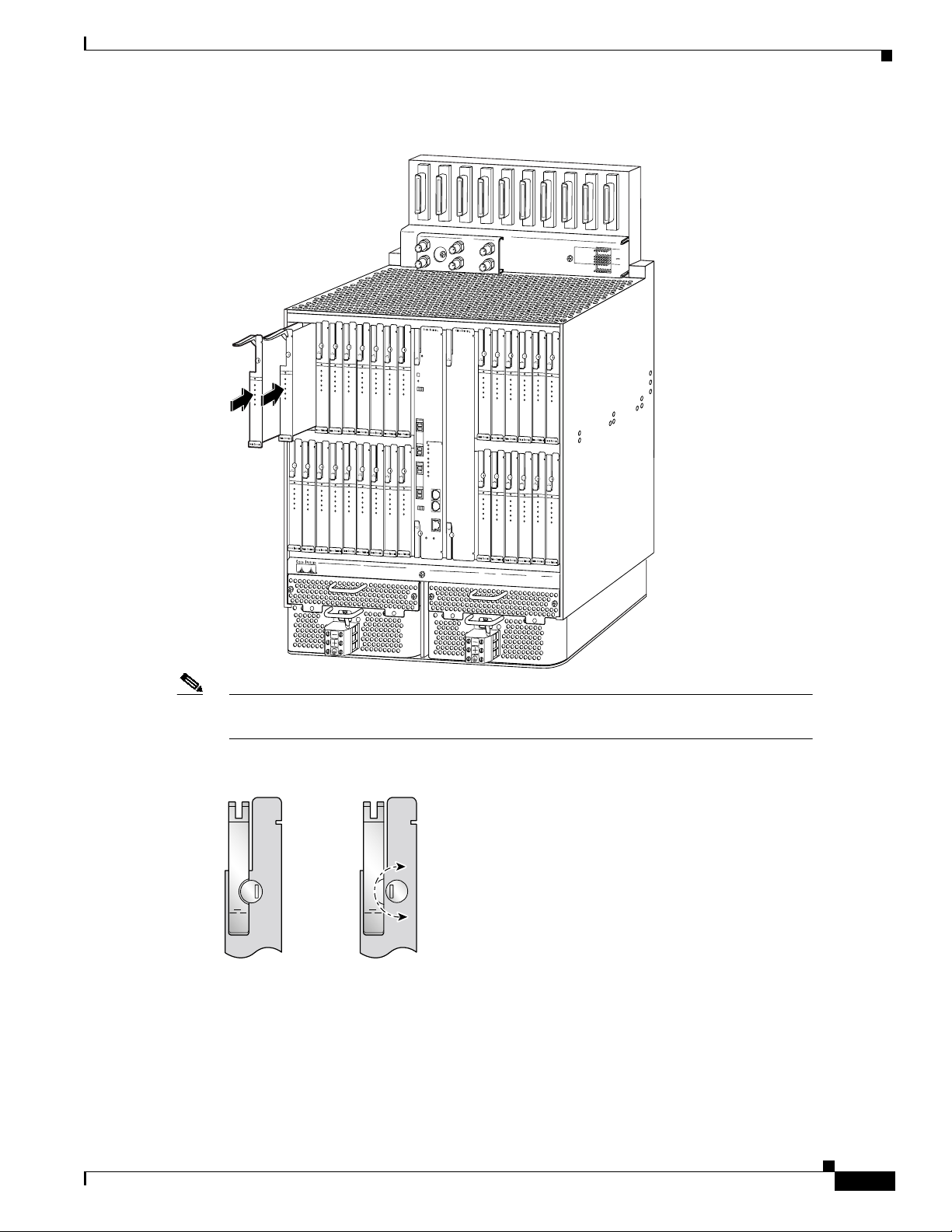
Figure 1 Cisco 6260 DSLAM—Line Card Insertion
NI-2
NI
-155SM-155SM
BLANK
STATUS
STATUS
STATUS
STATUS
STATUS
STATUS
ACTIVE
ACTIVE
STATUS
STATUS
ACTIVE
ATU-C 1
ACTIVE
ATU-C 2
ATU-C 1
ATU-C 3
ATU-C 2
ATU-C 4
ATU-C 3
ATU-C 4
ATUC-1
-4DMT
STATUS
ACTIVE
ATU-C 1
ATU-C 2
ATU-C 3
ATU-C 4
ATUC-1
-4DMT
ACTIVE
ATU-C 1
ATU-C 1
ATU-C 1
ATU-C 2
ATU-C 2
ATU-C 2
ATU-C 3
ATU-C 3
ATU-C 3
ATU-C 4
ATU-C 4
ATU-C 4
ATUC-1
ATUC-1
ATUC-1
-4DMT
-4DMT
-4DMT
STATUS
STATUS
STATUS
STATUS
ACTIVE
ACTIVE
ACTIVE
ACTIVE
ATU-C 1
ATU-C 1
ATU-C 1
ATU-C 1
ATU-C 2
ATU-C 2
ATU-C 2
ATU-C 2
ATU-C 3
ATU-C 3
ATU-C 3
ATU-C 3
ATU-C 4
ATU-C 4
ATU-C 4
ATU-C 4
ATUC-1
ATUC-1
ATUC-1
-4DMT
ATUC-1
-4DMT
-4DMT
-4DMT
STATUS
ACTIVE
ACTIVE
ACTIVE
ACTIVE
ATU-C 1
ATU-C 2
ATU-C 3
ATU-C 4
ATUC-1
-4DMT
STATUS
ACTIVE
ATU-C 1
ATU-C 2
ATU-C 3
ATU-C 4
ATUC-1
-4DMT
ACO
ATU-C 1
ATU-C 1
ATU-C 1
RESET
ATU-C 2
ATU-C 2
ATU-C 2
TRUNK 1
ATU-C 3
ATU-C 3
ATU-C 3
T
R
T
R
ATU-C 4
ATU-C 4
ATU-C 4
X
X
E
C
S
L
S
S
T
K
T
T
A
A
T
T
ATUC-1
ATUC-1
ATUC-1
-4DMT
-4DMT
-4DMT
ALARMS
CRITICAL
MAJOR
MINOR
POWER
STATUS
ACTIVE
FAN 1
STATUS
ACTIVE
ATU-C 1
ATU-C 2
ATU-C 3
ATU-C 4
ATUC-1
-4DMT
FAN 2
STATUS
STATUS
C
N
ACTIVE
ACTIVE
S
L
ATU-C 1
ATU-C 1
A
ATU-C 2
ATU-C 2
SBTD 2
U
ATU-C 3
X
ATU-C 3
T
R
T
R
X
X
E
ATU-C 4
C
ATU-C 4
S
L
S
S
T
K
T
T
E
A
A
T
T
N
E
T
ATUC-1
ATUC-1
-4DMT
-4DMT
STATUS
STATUS
STATUS
STATUS
STATUS
ACTIVE
ACTIVE
ATU-C 1
ATU-C 1
ATU-C 2
ATU-C 2
ATU-C 3
ATU-C 3
ATU-C 4
ATU-C 4
ATUC-1
ATUC-1
-4DMT
-4DMT
STATUS
STATUS
ACTIVE
ACTIVE
ATU-C 1
ATU-C 1
ATU-C 2
ATU-C 2
ATU-C 3
ATU-C 3
ATU-C 4
ATU-C 4
ATUC-1
ATUC-1
-4DMT
-4DMT
STATUS
ACTIVE
ACTIVE
ACTIVE
ACTIVE
ATU-C 1
ATU-C 1
ATU-C 1
ATU-C 1
ATU-C 2
ATU-C 2
ATU-C 2
ATU-C 2
ATU-C 3
ATU-C 3
ATU-C 3
ATU-C 3
ATU-C 4
ATU-C 4
ATU-C 4
ATU-C 4
ATUC-1
ATUC-1
ATUC-1
-4DMT
ATUC-1
-4DMT
-4DMT
-4DMT
STATUS
STATUS
STATUS
STATUS
ACTIVE
ACTIVE
ACTIVE
ACTIVE
ATU-C 1
ATU-C 1
ATU-C 1
ATU-C 1
ATU-C 2
ATU-C 2
ATU-C 2
ATU-C 2
ATU-C 3
ATU-C 3
ATU-C 3
ATU-C 3
ATU-C 4
ATU-C 4
ATU-C 4
ATU-C 4
ATUC-1
ATUC-1
ATUC-1
-4DMT
ATUC-1
-4DMT
-4DMT
-4DMT
Cisco 6260
PEM 1/PEM 2
AUD_CRIT/AUD_MAJ
AUD_MIN/VIS_CRIT
VIS_MAJ/VIS_MIN
STAT_ALARMS
BUS_A/BITS_B
Installing and Removing Line Cards
60V
0.5 A MAX
LOGIC
INPUTS
BITS
CLOCK
26394
Note The Cisco 6260 Hardware Installation and Troubleshooting Guide describes the Cisco 6260
DSLAM-slot modem tip and ring mapping to backplane connectors.
Figure 2 Typical Line Card Locking Tab
Locked
position
Unlocked
position
27035
78-10981-01
Cisco ATUC-4DMT-ISDN Line Card Installation and Configuration
7
Page 8

Installing and Removing Line Cards
Line Card Removal
This section describes how to remove a line card. You do not need to disconnect power before you
remove a line card from its slot in a Cisco 6260 DSLAM chassis. The following procedure describes
how to remove a line card.
Caution Static voltages as low as 30 volts can cause latent damage to circuitry. Be sure to observe all
standard antistatic procedures (for example, wear a grounding strap).
Step Procedure
Step 1
Step 2
Step 3
Step 4
Step 5
Rotate the line card locking tab to its unlocked position (see Figure 2).
Grasp the line card extraction lever (see Figure 1). Pull up the locking lever to disengage the
line card contact fingers from the backplane connector.
Slide the line card out of the chassis.
Place the line card on an antistatic surface. For extended storage, insert the line card into a
static-shielding bag or into a box lined with static-shielding material.
If you do not replace the removed line card with another line card, install a blank faceplate
(refer to “Line Card Installation” section on page 5).
Cisco ATUC-4DMT-ISDN Line Card Installation and Configuration
8
78-10981-01
Page 9

Line Card Faceplate Description
In addition to its locking mechanism (Figure 3), the faceplate contains two LEDs that show you line
card activity and status, and four other LEDs that show the activity of each modem during operation.
Figure 3 Faceplate—ATUC-4DMT-ISDN Line Card
1
2
STATUS
3
ACTIVE
4
ATU-C 1
ATU-C 2
5
ATU-C 3
ATU-C 4
Line Card Faceplate Description
ATUC
-4DMT-ISDN
6
38352
Line Card LED Indicators
The Status and Active light-emittingdiode (LED)indicators onthe linecard faceplateindicate line card
activity during operation. The faceplate also includes four modem-status LED indicators, one for each
modem in the line card. Table 2 describes LEDs on the ATUC-4DMT-ISDN line card.
Table 2 Line Card LEDs
LED Color and State Indication
Status Solid green No internal faults,line card iscommunicating with the
NI-2 processor card.
Blinking slow green No internalfaults, linecard isestablishing connection
with the NI-2 processor.
Off This line card has not booted or is operating
improperly.(During reboot, this linecard mightbe off
for 2 to 3 seconds.)
Blinking slow red An internal fault has occurred or the line card cannot
boot.
78-10981-01
Cisco ATUC-4DMT-ISDN Line Card Installation and Configuration
9
Page 10

Line Card Faceplate Description
Table 2 Line Card LEDs (continued)
Active Solid green Running application code, no digital signal processor
(DSP) microcode is downloading.
Blinking fast green Running application code and DSP microcode is
downloading.
Note Never interrupt a microcode download.
ATU-C 1
through
ATU-C 4
modem ports
Solid green The port is active and trained with its CPE device.
Blinking green The port is training with its CPE device.
Off The port is shut down or no CPE device detected.
Line Card Operation
After theline carddetects the CPE and completes the initializationsequence, itconfigures itself for one
of the following types of operation
• Upstream data rates—32 to 864 kbps in increments of 32 kbps
• Downstream data rates—32 to 8032 kbps in increments of 32 kbps
• Symmetrical data rate—Matches upstream and downstream rates
• Attained modem rate—The line card must obtain and report the actual acquired modem rate if the
desired rate cannot be achieved or if the line card adaptively selects the rate
Cisco NI-2 Network Interface Processor Module Functions
After a reset, the NI-2 network interface processor executes boot Flash EPROM routines. Boot flash
code alsocontains theserial managementbus (SMB)boot loader. TheNI-2 networkinterface processor
module sends each line card its run-time image over the SMB and loads the main executable code into
SRAM. After the main-code image loads and runs, the line card loads its serial data bus (SDB) Utopia
field programmable gate array (FPGA) and initializes all modems.
ATM Virtual Circuit Support
Each line card supports up to 256 virtual channel identifiers (VCIs) and virtual path identifiers (VPIs)
per port. Each line card also enables use of default VPI/VCI mapping or provisioning of
VPI/VCI mapping by means of Cisco IOS configuration commands.
Configuring Software for a Line Card
For Cisco IOS software configuration information and support, refer to the Configuration Guide for
Cisco 6000 Family DSLAMs with NI-2 and tothe Command Reference for Cisco 6000Family DSLAMs
with NI-2 in the Cisco IOS software configuration documentation set that corresponds with thesoftware
release installed on your Cisco 6260 NI-2 DSLAM hardware.
Cisco ATUC-4DMT-ISDN Line Card Installation and Configuration
10
78-10981-01
Page 11

Line Card Direct Connect Deployment
Figure 4 shows the physical DMT data and installed interface relationships among devices in a typical
ATUC-4DMT-ISDN direct connect line card deployment in a Cisco 6260 DSLAM.
Figure 4 Typical ATUC-4DMT-ISDN Direct-Connect Line Card Deployment
Line Card Direct Connect Deployment
PCs
Cisco
677i
CPE
CPE
CPE
1
2
1
Ethernet
port
DMT
port
DMT
DMT
From W AN
network trunk
ATM
Cisco 6260
1
Line cards
LC
2
DMT
1
1
LC
Line
1
M
Line
2
D
2
Line
3-N
F
DMT
network trunk
Cisco
NI-2
2
Rack
To WAN
LC
N
DMT
ATM
3-N
Central office
78-10981-01
DMT
CPE – CPE
3 N
3- N
Outside plant
loop
43846
In direct connect deployments, Cisco ATUC-4DMT-ISDN line cards are a principal component of the
Cisco 6260 DSLAM normally located in a CO facility rack. You install from 1 to N (where N has any
value up to 30) line cards in a single Cisco 6260 DSLAM.
The network configuration consists of the following two principal hardware groups
• Customer premises equipment (CPE)
• CO facility equipment
Cisco ATUC-4DMT-ISDN Line Card Installation and Configuration
11
Page 12

Line Card Direct Connect Deployment
CPE Hardware Group
The CPE hardware group (see Figure 4) consists of customer and telco equipment. Customer
PC equipment connected to a customer Ethernet LAN receives and transmits Ethernet data only. The
Cisco 677i modem is telco equipment that interfaces with an Ethernet line and converts Ethernet data
to DMT signals. Customers must use a telco-provided Cisco 677i modem to produce DMT signals for
proper ATUC-4DMT-ISDN line card operation.
This section describes how the component configuration illustrated in Figure 4 relates to proper line
card operation.
Cisco 677i Modem
At a customer site, you must use the Cisco 677i modem to provide the Ethernet LAN interface (see
Figure 4) at the downstream endof theline. The677i modemprovides theinterface betweena customer
Ethernet and a line card. Specifically, the customer Cisco 677i modem provides the network
ATUC-R DMT signaling function, which
• Has an Ethernet port that interfaces physically with an Ethernet LAN
• Converts line card downstream DMT signaling to its Ethernet data equivalent for transfer to the
customer Ethernet LAN
• Has a DMT port that interfaces physically with the outside plant loop
• Convertsupstream Ethernet data to an equivalent DMT signal for transfer to theline cards through
the telco CO facility MDF
CO Facility Hardware Group
The CO facility hardware group (see Figure 4) consists of
• The telco MDF
• Cisco equipment housed in a telco rack containing one or more Cisco 6260 DSLAMs with line
cards LC1, and LC2 through LCN(where N can have any value between 3 and 30)
The CO facility equipment routes signals DMT1, DMT2, and DMT3 through DMTN between the
CPE 677i modems and the MDF.
In the:
• Upstream direction—Line cards convert DMTsignals to ATM formatted cells for application to the
NI-2 interface processor modules
• Downstream direction—Line cards convert ATM cells to DMT signals for application to the
MDF and customer modems
Cisco equipment using these line cards includes
• One or more Cisco 6260 DSLAMs in telco racks
• Up to 30 line cards in each Cisco 6260 DSLAM
• An NI-2 network interface processor module in each 6260 DSLAM
12
Cisco ATUC-4DMT-ISDN Line Card Installation and Configuration
78-10981-01
Page 13

Main Distribution Frame
The MDF (see Figure 4) is telco equipment that distributes customer DMT signals from a
Cisco 677i modem to its corresponding internal modem on a line card through suitable
MDF to Cisco 6260 DSLAM cabling. Cisco product offerings include prefabricated Champion cable
assemblies in various lengths for connection of customerlines between aCO facility MDF and theline
card connectors on Cisco 6260 DSLAM backplanes. You make these cable connections at Cisco 6260
backplane receptacles. Refer to the Cisco 6260 Hardware Installation and Troubleshooting Guide for
cabling instructions.
Line Cards
In Figure 4, Cisco ATUC-4DMT-ISDN line cards LC1and LC2through LCN convert upstream
DMT signals to AMT cells and downstream AMT cells to DMT signals. The Cisco NI-2 interface
processor module controls each line card, which
• Connects up to four line pairs that transport DMT signals between the line card modems and the
NI-2 module through the MDF
• Converts DMT signals, routed from the customer modems, to WAN trunk ATM cells
• Converts WAN trunk ATM cells, routed from the NI-2 module, to modem DMT signals
A full complement of line cards in a single Cisco 6260 DSLAM can handle network communications
from and to as many as 120 customers.
You can install up to four Cisco 6260 DSLAMs, populated with ATUC-4DMT-ISDN line cards in a
direct connect configuration, in a standard NEBS compliant 7-foot CO facility rack.
Line Card Splitter Deployment
Cisco NI-2 Network Interface Processor Module
The Cisco NI-2 network interface processor module (see Figure 4) in the Cisco 6260 DSLAM and the
Cisco IOS software running on the Cisco NI-2 control how ATM cells are processed when transported
between the line cards and the WAN network trunk.
The NI-2 processor module
• Collects ATM cells fromthe WAN network trunk intended for customers connected tothe linecard
modems through the Cisco 6260 DSLAM and the telco MDF
• Distributes WAN network trunk ATM cells through the Cisco 6260 DSLAM line cards as
DMT signals among addressed customers connected to the line card modems
The Cisco NI-2 Card Installation and Configuration for the Cisco 6260 document describes the
NI-2 network interface processor module.
Line Card Splitter Deployment
Figure 5 shows the DMT/ISDN data and system interface relationships among devices in a typical
ATUC-4DMT-ISDN line card deployment using DMT/ISDN splitters.
78-10981-01
Cisco ATUC-4DMT-ISDN Line Card Installation and Configuration
13
Page 14

Line Card Splitter Deployment
Figure 5 Line Card Splitter Deployment—ISDN and Data DMT/ISDN Network
ISDN T1
ISDN
NT1
dev
ISDN
CPE
1
PCs
Cisco
677i
1
DMT/ISDN
CPE splitter
CPE
1
CPE
2
Ethernet
port
DMT
port
DMT/ISDN
DMT/ISDN
From W AN
network trunk
ATM
To WAN
network trunk
ATM
Cisco
NI-2
Cisco 6260
Line cards
1
LC
LC
1
2
DMT
DMT
Line
1
M
Line
2
D
2
Line
F
3-N
1
DMT/ISDN
CO splitter
LC
N
DMT
2
3-N
Rack
ISDN
ISDN
1
2
ISDN
3-N
ISDN exchange
DMT/ISDN
3-N
Central office
40720
Outside plant
CPE – CPE
3N
loop
In DMT/ISDN line card deployments, you use CPE and CO splitters to separate the two signals.
DMT/ISDN splitters permit both telephone voice and data signals to be transported as data fromand to
the CPE. You can install as many as 30 ATUC-4DMT-ISDN line cards in a single splitter-configured
Cisco 6260 DSLAM.
The network configuration consists of the two following principal hardware groups:
• The CPE facility
• The CO facility
14
Cisco ATUC-4DMT-ISDN Line Card Installation and Configuration
78-10981-01
Page 15

CPE Hardware Group
The CPE hardware group (see Figure 5) consists of customer and telco equipment that transmits and
receives both ISDN and DMT signals and PC equipment that transmits and receives Ethernet data. A
typical CPE hardware group (for example, CPE1) consists of
• ISDN terminal equipment
• A network NT1 device
• A Cisco 677i modem
• A DMT/ISDN splitter
The following sections describe the components that make up a typical splitter-configured
CPE hardware group.
ISDN Terminal Equipment
ISDN terminal equipment
• Provides ISDN services such as telephony and data terminal applications
• Provides upstream and downstream ISDN signaling functions
Line Card Splitter Deployment
NT1 Device
The NT1 device (see Figure 5) includes two ports that typically provide an interface to the
customer ISDN terminal equipment and the CPE DMT/ISDN splitter. The NTI device passes properly
formatted 2B1Q or 4B3T signals (see Table 3) to the splitter.
Cisco 677i Modem
In this deployment, the Cisco 677i modem (seeFigure 5 ) also provides the Ethernet primary interface.
The Cisco 677i modem transmits and receives DMT signals or Ethernet data passed between the local
DMT/ISDN CPE splitter and the customer LAN. Specifically, the Cisco 677i modem provides the
required ATUC-R function, which
• Converts line card downstream DMT signaling to its Ethernet data equivalent for transfer to the
customer Ethernet LAN
• Convertsupstream Ethernet data to an equivalent DMT signal for transfer to theline cards through
the CPE DMT/ISDN splitter
The DMT port interfaces physically with the CPE DMT/ISDN splitter. The modem ports must be used
to transport data traffic over an ADSL access network.
CPE DMT/ISDN Splitter
The CPE DMT/ISDN splitter (Figure 5) electrically couples the ISDN signal from the NT1 device and
the DMTsignal from the modem ontothe paircarrying the DMT/IDSN traffic between theCPE facility
and the MDF at the CO facility. The CPE splitter provides a filtering function that
• Separates ISDN and DMT signals from the composite downstream signal
• Feeds the downstream ISDN signal to the local NT1 device
78-10981-01
Cisco ATUC-4DMT-ISDN Line Card Installation and Configuration
15
Page 16

Line Card Splitter Deployment
• Feeds the line card downstream DMT signal to the Cisco 677i modem forconversion to equivalent
Ethernet data for application to the customer LAN
• Combines upstream ISDN and DMT signals from the subscriber modem into a DMT/ISDN data
stream for application to the CO facility DMT/ISDN splitter through the MDF
CO Facility Hardware Group
The CO facility hardware group consists of Cisco and telco equipment that processes both ISDN and
DMT signals (see Figure 5). The CO facility Cisco equipment transfers DMT signals between local
DSL subscribers and the wide area network (WAN) trunk interface through the MDF, the
DMT/ISDN CO splitter, and the line cards. Cisco equipment includes
• One or more Cisco 6260 DSLAMs
• Up to 30 line cards in each DSLAM
• An NI-2 network interface processor module in each Cisco 6260 DSLAM
Other equipment at the CO facility associated with DMT/ISDN signal processing includes
• The MDF
• One or more CO facility DMT/ISDN splitters
• A PSTN ISDN exchange switch
This section describes the relationship between the line cards and the components in the CO facility
hardware group illustrated in Figure 5.
Main Distribution Frame
The MDF distributes DMT/ISDN signals (see Figure 5)
• From subscriber CPE splitters to the CO facility DMT/ISDN splitter
• From the CO facility DMT/ISDN splitter to the subscriber CPE DMT/ISDN splitter
DMT/ISDN CO Splitter
The telco facility DMT/ISDN CO splitter (see Figure 5):
• Separates combined line signals DMT/ISDN
distribution to the line cards and to the PSTN ISDN exchange, respectively
• Electrically combines line card signal DMT
through DMTN with signals ISDN2through ISDNNfor distribution on the same line pair to the
DMT/ISDN CPE splitter through the MDF
Line Cards
ATUC-4DMT-ISDN line cards function as described in the “Line Cards” section on page 13. In
Figure 5, Cisco line cards LC1and LC2through LCNconvert upstream DMT signals to AMT cells and
downstream AMT cells to DMT signals.
Because a CO DMT/ISDN splitter is required with each 6260 DSLAM, you can only install two
Cisco 6260 DSLAMs, populated with ATUC-4DMT-ISDN line cards, in a splitter-configured standard
NEBS compliant 7-foot CO facility rack.
and DMT/ISDN2 through DMT/ISDNN for
1
with ISDN exchange signal ISDN1and signals DMT
1
2
16
Cisco ATUC-4DMT-ISDN Line Card Installation and Configuration
78-10981-01
Page 17

Cisco NI-2 Network Interface Processor Module
The “Cisco NI-2 Network Interface Processor Module” section on page 13 briefly describes the Cisco
NI-2 network interface processor module (see Figure 4 and Figure 5).
Acronyms and Terms
Table 3 defines the following terms that are used in this guide.
Table 3 Acronyms and Term Definitions
Acronym/Term Definition
2B1Q An ISDN line coding technique used in the USA and
Europe
4B3T An ISDN line coding technique used in Germany
AAL5 ATM adaption Layer 5
ADSL Asymmetric digital subscriber line
ANSI American National Standards Institute
ATM Asynchronous Transfer Mode
ATUC or ATU-C Central office ADSL transceiver unit
CCO Cisco Connection Online
CO Central office
CPE Customer premises equipment
DMT Discrete multi-tone
DSB Data serial bus
DSP Digital signal processor
DSLAM Digital subscriber line access multiplexer
DSL Digital subscriber line
EMI Electromagnetic interference
EPROM Erasable programmable read-only memory
ESD Electrostatic discharge
FAQ Frequently asked questions
FCC Federal Communications Commission
FPGA Field programmable gate array
FTP File Transfer Protocol
G.dmt Standard that defines ADSL over splitter-coupled
interfaces.
GFR Guaranteed frame rate
GND Ground
HEC Header error control
I/O Input/output
Acronyms and Terms
78-10981-01
Cisco ATUC-4DMT-ISDN Line Card Installation and Configuration
17
Page 18

More Information
Table 3 Acronyms and Term Definitions (continued)
Acronym/Term Definition
ISDN Integrated Services Digital Network
ITU International Telecommunications Union
LED Light emitting diode
MIB Management Information Base
NI-2 Network interface module type 2
NT1 ISDN network terminal type 1
PEM Power entry module
PSTN Public switched telephone network
SDB Serial data bus
SMB Serial management bus
SRAM Serial random-access memory
TAC Cisco technical assistance center
VCI Virtual channel identifier
VPI Virtual path identifier
VIS Visible
More Information
Your Cisco 6260 NI-2 DSLAM and Cisco IOS software running on an NI-2 module installed in
Cisco 6260 NI-2 DSLAMs have extensive features and functionality, which are documented in the
following resources:
• For Cisco IOSsoftware configuration informationand support, refer to the ConfigurationGuide for
Cisco 6000 Family DSLAMs with NI-2 and the Command Reference for Cisco 6000 Family
DSLAMs with NI-2 in the Cisco IOS software configuration documentation set that corresponds
with the software release installed on your Cisco 6260 NI-2 DSLAM hardware.
• You can access Cisco IOS software configuration and hardware installation and maintenance
documentation on the World Wide Web at http://www.cisco.com, http://www-china.cisco.com, or
http://www-europe.cisco.com.
• For hardware installation and maintenance information about Cisco 6260 NI-2 DSLAMs, refer to
the Cisco 6260 Hardware Installation and Troubleshooting User Guide.
• For hardware installation and maintenance information about the Cisco 6260 NI-2 DSLAM
module, refer to the NI-2 Line Card Installation and Configuration for the Cisco 6260 document.
• For hardware installation informationabout the Cisco6260 NI-2 DSLAM system I/Ocard, refer to
Cisco 6260 Hardware Installation and Troubleshooting User Guide.
• To view Cisco documentation or obtain general information about the documentation, see the
“Cisco Connection Online” section on page 19 or the “Documentation CD-ROM” section on
page 20, or call Customer Service at 800 553-6387 or 408 526-7208. Customer Service hours are
5:00 a.m. to 6:00 p.m. Pacific time, Monday through Friday (excluding company holidays). You
can also send e-mail to cs-rep@cisco.com, or refer to the Cisco Information Packet that shipped
with your line card.
18
Cisco ATUC-4DMT-ISDN Line Card Installation and Configuration
78-10981-01
Page 19

Related Documentation
Refer to the following documents for more information about the operation and components of the
Cisco 6100 series DSLAMs:
• NI-2 Card Installation and Configuration for the Cisco 6260
• ATUC-4DMT-ISDN Card Installation and Configuration for the Cisco 6260
• Cisco 6260 PEM and Fan Tray Installation and Replacement
• Cisco 6100 Series DSLAM Release Notes for Cisco IOS Release 12.0(5)DA
• Cisco DSL Manager User Guide
• Cisco DSL Manager Concepts Manual
• Cisco DSL Manager Management Tool Kit
• Cisco DSL Manager Quick Start Guide
FCC Class B Compliance
This equipment has been tested and found to comply with the limits for a Class A digital device,
pursuant topart 15 of the FCCrules. These limitsare designed to provide reasonableprotection against
harmful interference when the equipment is operated in a commercial environment. This equipment
generates, uses, andcan radiateradio-frequency energy and,if notinstalled and usedin accordancewith
the instruction manual, may cause harmful interference to radio communications. Operation of this
equipment in a residential area is likely to cause harmful interference, in which case users will be
required to correct the interference at their own expense.
You can determinewhether your equipment iscausing interference by turningit off. If the interference
stops, it was probably caused by the Cisco equipment or one of its peripheral devices. If the equipment
causes interference to radio or television reception, try tocorrect the interference by using one or more
of the following measures:
• Turn the television or radio antenna until the interference stops.
• Move the equipment to one side or the other of the television or radio.
• Move the equipment farther away from the television or radio.
• Plug the equipment into an outletthat is on a different circuit from the television or radio. (That is,
make certain the equipmentand thetelevision orradio areon circuitscontrolled bydifferent circuit
breakers or fuses.)
Cisco Connection Online
Note The ATUC-4DMT-ISDN line card is designed to meet these requirements. Modifications
to this product that are not authorized by Cisco Systems, Inc., may void variousapprovals
and negate your authority to operate this product.
Cisco Connection Online
Cisco Connection Online (CCO) is the Cisco Systems primaryreal-time support channel. Maintenance
customers and partners may self-register at CCO to obtain additional information and services.
78-10981-01
Cisco ATUC-4DMT-ISDN Line Card Installation and Configuration
19
Page 20

Documentation CD-ROM
Available 24 hours a day, 7 days a week, CCO provides a wealth of standard and value-added services
to Cisco customers and business partners. CCO services include product information, product
documentation, software updates, release notes, technical tips, the Bug Navigator, configuration notes,
brochures, descriptions of service offerings, and download access to public and authorized files.
CCO serves a wide variety of users through two interfaces that are updated and enhanced
simultaneously: a character-basedversionand amultimedia version thatresides on theWorldWideWeb
(WWW). The character-based CCO supports Zmodem, Kermit,Xmodem, FTP, andInternet e-mail,and
it is excellent for quick access to information over lower bandwidths. The WWW version of CCO
provides richly formatted documents with photographs, figures, graphics, and video, as well as
hyperlinks to related information.
You can access CCO in the following ways:
• WWW: http://www.cisco.com
• WWW: http://www-europe.cisco.com
• WWW: http://www-china.cisco.com
• Telnet: cco.cisco.com
• Modem: From North America, 408 526-8070; from Europe, 33 1 64 46 40 82. Use the following
terminal settings: VT100 emulation; databits: 8; parity: none; stop bits: 1; and connection rates up
to 28.8 kbps.
For a copy of CCO Frequently Asked Questions (FAQ), contact cco-help@cisco.com. For additional
information, contact cco-team@cisco.com.
If you are a network administrator and need personal technical assistance with a Cisco product that is
under warranty or covered by a maintenance contract, contact the Cisco Technical Assistance Center
(TAC) at 800 553-2447, 408 526-7209, or tac@cisco.com. To obtain general information about Cisco
Systems, Cisco products, or upgrades, contact 800 553-6387, 408 526-7208, or cs-rep@cisco.com.
Documentation CD-ROM
Cisco documentation and additional literature are available in a CD-ROM package, which ships with
your product. The Documentation CD-ROM, a member of the Cisco Connection Family, is updated
monthly.Therefore, it might be more current than printed documentation. To order additionalcopies of
the Documentation CD-ROM, contact your local sales representative or call customer service. The
CD-ROM package is available as a single package or through an annual subscription.
If you are reading Cisco product documentation on the World Wide Web, you can submit comments
electronically.Click Feedbackin the toolbarand select Documentation.After you completethe form,
click Submit to send it to Cisco. We appreciate your comments.
Cisco Documentation Feedback
If you are reading Cisco product documentation on the World Wide Web, you can submit comments
electronically.Click Feedbackin the toolbarand select Documentation.After you completethe form,
click Submit to send it to Cisco. We appreciate your comments.
20
Cisco ATUC-4DMT-ISDN Line Card Installation and Configuration
78-10981-01
Page 21

Cisco Documentation Feedback
Copyright © 2000, Cisco Systems, Inc. Allrightsreserved. Access Registrar, AccessPath, Are You Ready, ATM Director, Browse with Me,CCDA,CCDE, CCDP, CCIE, CCNA, CCNP, CCSI, CD-PAC, CiscoLink, the Cisco
NetWorks logo, the Cisco Powered Network logo, Cisco Systems Networking Academy, Fast Step, FireRunner, Follow Me Browsing, FormShare, GigaStack, IGX, Intelligence in the Optical Core, Internet Quotient, IP/VC, iQ
Breakthrough, iQ Expertise, iQ FastTrack, iQuick Study, iQ Readiness Scorecard, The iQ Logo, Kernel Proxy, MGX, Natural Network Viewer, Network Registrar, the Networkers logo, Packet, PIX, Point and Click
Internetworking, Policy Builder, RateMUX, ReyMaster,ReyView,ScriptShare,Secure Script, Shop with Me, SlideCast, SMARTnet, SVX, TrafficDirector, TransPath, VlanDirector, Voice LAN,WavelengthRouter,Workgroup
Director, and Workgroup Stack are trademarks of Cisco Systems, Inc.; Changing the Way We Work, Live, Play, and Learn, Empowering the Internet Generation, are service marks of Cisco Systems, Inc.; and Aironet, ASIST,
BPX, Catalyst, Cisco, the Cisco Certified Internetwork Expert Logo, Cisco IOS, the Cisco IOS logo, Cisco Press, Cisco Systems, Cisco Systems Capital, the Cisco Systems logo, Collision Free, Enterprise/Solver, EtherChannel,
EtherSwitch, FastHub, FastLink, FastPAD, IOS, IP/TV, IPX, LightStream, LightSwitch, MICA, NetRanger, Post-Routing, Pre-Routing, Registrar, StrataView Plus, Stratm, SwitchProbe, TeleRouter, are registered trademarks of
Cisco Systems, Inc. or its affiliates in the U.S. and certain other countries.
All other brands, names, or trademarksmentionedinthis document/website are the property of their respective owners. The use of the word partner doesnotimplya partnership relationship between Cisco and any of its resellers.
(0008R)
Cisco ATUC-4DMT-ISDN Line Card Installation and Configuration
78-10981-01
21
Page 22

Cisco Documentation Feedback
22
Cisco ATUC-4DMT-ISDN Line Card Installation and Configuration
78-10981-01
 Loading...