

Page 1

Your ATA
Your New ATA, page 1
•
Devices Associated with Your ATA, page 1
•
Cisco ATA 191 and ATA 192 Hardware, page 2
•
Install Your New ATA, page 6
•
Phone Adapter Configuration Utility, page 7
•
Supported ATA Call Features, page 8
•
Your New ATA
Your analog telephone adapter (ATA) allows you to connect an analog device, such as an analog phone or
fax machine, to your network. The connected device can then function like the IP phones in your network.
Your new analog telephone adapter (ATA) has two interfaces:
•
•
Two RJ11 ports for analog devices
A RJ45 port for Ethernet
Light-emitting diodes (LEDs) on the ATA provide status.
Install your ATA with the components that are included in the box.
You'll perform these tasks:
Install your ATA with the components in the box.
•
Devices Associated with Your ATA
Use your ATA to connect these types of devices to your network:
Analog phones
•
Analog phones have no softkeys.
◦
The information that analog phones display depends on the model you have.
◦
Cisco ATA 191 and ATA 192 Analog Telephone Adapter User Guide for Multiplatform Firmware
1
Page 2

Cisco ATA 191 and ATA 192 Hardware
◦ You use the phone’s flash button for hold, resume, transfer, and conference.
Analog telephony voice devices
•
The ATA supports analog telephony voice devices, such as overhead paging adapters and answering
◦
machines, that emulate a regular phone.
Overhead paging systems
•
Overhead paging systems provide alarms and public-address announcements in buildings.
◦
Fax machines
•
◦ Use a fax machine directly with an ATA. Don’t connect an extension to a fax machine, and don’t
use the fax machine with a splitter.
To reduce fax failures, use overseas mode, if available; if not, set the fax machine transmission
◦
speed to low.
Data devices, such as facsimile machines and modems, may not function optimally. For the best
◦
fax and modem performance, continue to use a dedicated PSTN line.
Your ATA
Cisco ATA 191 and ATA 192 Hardware
The ATA 191 and ATA 192 are compact, easy to install devices.
The unit provides these connectors:
5V DC power connector.
•
• Two RJ-11 FXS (Foreign Exchange Station) ports—The ATA 191 and ATA 192 have two RJ-11 phone
ports that work with any standard analog phone device. Each port supports either voice calls or fax
sessions, and both ports can be used simultaneously.
• The ATA 191 and ATA 192 both have one WAN network port—An RJ-45 10/100BASE-T data port
to connect an Ethernet-capable device to the network.
The ATA 192 includes an extra LAN Ethernet port—An RJ-45 10/100BASE-T data port to connect to
a device on your network, such as a computer, using an Ethernet cable.
Note
The ATA network port performs autonegotiation for duplex and speed. It supports speeds of 10/100 Mbps
and full-duplex.
Cisco ATA 191 and ATA 192 Analog Telephone Adapter User Guide for Multiplatform Firmware
2
Page 3
Your ATA
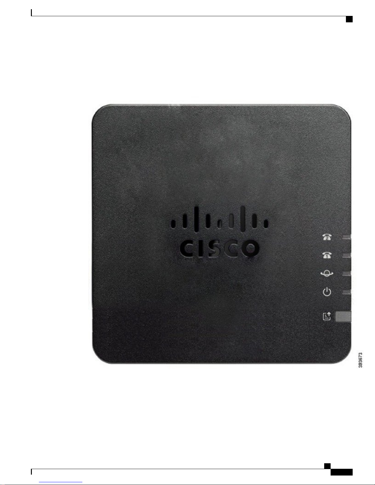
ATA 191 and ATA 192 Top Panel
Figure 1: ATA 191 and ATA 192 Top Panel
ATA 191 and ATA 192 Top Panel
Cisco ATA 191 and ATA 192 Analog Telephone Adapter User Guide for Multiplatform Firmware
3
Page 4

ATA 191 and ATA 192 Top Panel
Table 1: ATA 191 and ATA 192 Top Panel Items
Your ATA
DescriptionItem
Power LED
Network LED
Phone 1 LED
Phone 2 LED
Problem Report Tool (PRT) Button
Steady green: System booted up successfully and is ready for use.
Slow flashing green: System is booting up.
Fast flashing green three times, then repeats: System failed to boot
up.
Off: Power is off.
Flashing green: Data transmission or reception is in progress through
the WAN port.
Off: No link.
Steady green: On hook.
Slow flashing green: Off hook.
Fast flashing green three times, then repeats: The analog device
failed to register.
Off: The port is not configured.
Press this button to create a problem report using the Problem Report
Tool.
Note
This button is not a power button. When you press this button,
a problem report is generated and uploaded to a server for the
system administrator.
Problem Report Tool (PRT) LED
Problem Report Tool Button
The Problem Report Tool (PRT) button is on the ATA top panel. Press the PRT button, and a log file is
prepared and uploaded to the server for troubleshooting your network.
You can instruct your analog phone users to press the PRT button on the ATA device to start the PRT log file
process.
One of the following must be completed to upload the PRT log file from the ATA:
Flashing amber: The PRT is preparing the data for the problem report.
Fast Flashing amber: The PRT is sending the problem report log to
the HTTP server.
Solid green for five seconds, then off: The PRT report was sent
successfully.
Flashing red: The PRT report failed. Press the PRT button again to
trigger a new PRT report.
Blinking red: Press the PRT button once to cancel the blinking, then
press again to trigger a new PRT.
Cisco ATA 191 and ATA 192 Analog Telephone Adapter User Guide for Multiplatform Firmware
4
Page 5

Your ATA
Set up the HTTP server to upload the PRT log file from the ATA.
•
Configure the customer support upload URL to best suit your needs, and apply it to the ATA.
•
ATA 191 and ATA 192 Back Panel
Figure 2: ATA 191 Back Panel
ATA 191 and ATA 192 Back Panel
Figure 3: ATA 192—Back Panel
Table 2: ATA 191 and ATA 192 Back Panel Items
DescriptionItem
RESET
To restart the ATA, use a paper clip or similar object to press this button
briefly.
To restore the factory default settings, press and hold for 10 seconds.
Use an RJ-11 phone cable to connect an analog phone or fax machine.PHONE 1
Cisco ATA 191 and ATA 192 Analog Telephone Adapter User Guide for Multiplatform Firmware
5
Page 6

Install Your New ATA
Your ATA
DescriptionItem
PHONE 2
ETHERNET (ATA 192 only)
Install Your New ATA
Your ATA comes with everything to power it up, connect it to the network, and set it up on your desk.
Before You Begin
Before you begin the installation, make sure you have the following equipment:
Ethernet cable to connect to your network.
•
Analog phone or fax machine to connect to your ATA.
•
Phone cable to connect your phone.
•
Use an RJ-11 phone cable to connect a second analog phone or fax
machine.
Use an Ethernet cable to connect your ATA to a device on your network,
such as a computer.
Use an Ethernet cable to connect to the network.NETWORK
Use the power adapter that was provided to connect to a power source.DC 5V POWER
Step 1
Step 2
Uninterruptible power supply (UPS) to provide backup power.
•
Procedure
Connect the network cable to your network and to the NETWORK port on the ATA.
Connect the phone cable to the PHONE 1 port on the ATA and to your analog device (phone or fax machine).
Cisco ATA 191 and ATA 192 Analog Telephone Adapter User Guide for Multiplatform Firmware
6
Page 7

Your ATA
Phone Adapter Configuration Utility
If connecting a fax machine, connect it directly to the ATA. Do not connect an extension to a fax machine,
and do not use a splitter.
Step 3
Step 4
(Optional) If you have a second analog device, connect the phone cable to the PHONE 2 port on the ATA
and to your second analog device.
Connect the ATA power cable to the DC 5V POWER port on the ATA, and plug the power cable into your
power source.
Phone Adapter Configuration Utility
You can configure or customize some phone features with the Phone Adapter Configuration Utility webpage.
Your administrator gives you the page URL, your user ID, and password.
In the Configuration Utility page, you can view some network and administration settings, as well as some
basic information about your ATA, such as firmware version, serial number, and memory use.
Most people use the Phone Adapter Configuration Utility page to set up a few basic features such as Speed
dial or Call forward. To set up these features, refer to the following table.
Cisco ATA 191 and ATA 192 Analog Telephone Adapter User Guide for Multiplatform Firmware
7
Page 8

Supported ATA Call Features
Table 3: Configuration Utility Features
Your ATA
DescriptionFeature
Call forward and Selective call forward.
Speed dial.
Supplementary services.
Distinctive ring
You specify the number that will receive calls when
call forward is enabled on the phone. Use the
Configuration Utility page to set up more complicated
call forward functions, for example, when your line
is busy.
For more information, see Call Forward Settings or
Selective Call Forward Settings and Set Up Phone
Features with Phone Adapter Configuration Utility.
You assign phone numbers to a line so that you can
quickly call that person.
For more information, see Speed Dial Settings and
Set Up Phone Features with Phone Adapter
Configuration Utility
Configure such features as Call waiting, Do not
disturb, or Called ID.
For more information, see Supplementary Service
Settings and Set Up Phone Features with Phone
Adapter Configuration Utility
You can assign a specific ring to a phone number or
line.
For more information, see Distinctive Ring Settings
and Set Up Phone Features with Phone Adapter
Configuration Utility.
Ring setting
Supported ATA Call Features
Depending on your system configuration, your ATA supports some or all the following call features:
• Transfer (attended or supervised)—In this type of transfer, you talk to the receiving party before you
complete the transfer.
• Transfer (unattended or unsupervised)—In this type of transfer, you complete the transfer and hang up
before the receiving party answers.
Cisco ATA 191 and ATA 192 Analog Telephone Adapter User Guide for Multiplatform Firmware
8
You can assign a specific ring to a certain situation
such as when a call is on hold or during a call back.
For more information, see Ring Settings and Set Up
Phone Features with Phone Adapter Configuration
Utility.
Page 9

Your ATA
Supported ATA Call Features
Conference.
•
Hold and Resume.
•
Caller ID.
•
Call Waiting.
•
Call Pickup.
•
Speed Dial.
•
Music On Hold.
•
Shared Lines.
•
• Voicemail—This feature has no visual indicator, but a message waiting tone when you go off-hook
indicates that you have voice messages. Some analog phones with a large LCD screen may display a
voicemail icon.
Call Forward.
•
Redial.
•
Cisco ATA 191 and ATA 192 Analog Telephone Adapter User Guide for Multiplatform Firmware
9
Page 10

Supported ATA Call Features
Your ATA
Cisco ATA 191 and ATA 192 Analog Telephone Adapter User Guide for Multiplatform Firmware
10
 Loading...