

Page 1

Cisco ATA 186 and Cisco 18 8
Installation and Configuration
Guide
August, 2002
Corporate Headquarters
Cisco Systems, Inc.
170 West Tasman Drive
San Jose, CA 95134-1706
USA
http://www.cisco.com
Tel: 408 526-4000
800 553-NETS (6387)
Fax: 408 526-4100
Customer Order Number:
Text Part Number: OL-1267-01
Page 2

THE SPECIFICATIONS AND INFORMATION REGARDING THE PRODUCTS IN THIS MANUAL ARE SUBJECT TO CHANGE WITHOUT
NOTICE. ALL STATEMENTS, INFORMATION, AND RECOMMENDATIONS IN THIS MANUAL ARE BELIEVED TO BE ACCURATE BUT
ARE PRESENTED WITHOUT WARRANTY OF ANY KIND, EXPRESS OR IMPLIED. USERS MUST TAKE FULL RESPONSIBILITY FOR
THEIR APPLICATION OF ANY PRODUCTS.
THE SOFTWARE LICENSE AND LIMITED WARRANTY FOR THE ACCOMPANYING PRODUCT ARE SET FORTH IN THE
INFORMATIO N PACKET THAT SHIPPED WITH THE PRODUCT AND ARE INCORPORATED HEREIN BY THIS REFERENCE. IF YOU
ARE UNABLE TO LOCATE THE SOFTWARE LICENSE OR LIMITED WARRANTY, CONTACT YOU R CISCO REPRESENTATIVE FOR A
COPY.
The following information is for FCC compliance of Class A devices: This equipment has been tested and found to comply with the limits for a Class
A digital device, pursuant to part 15 of the FCC rules. These limits are designed to provide reasonable protection against harmful interference when
the equipment is operated in a commercial environment. This equipment generates, uses, and can radiate radio-frequency energy and, if not installed
and used in accordance with the instruction manual, may cause harmful interference to radio communications. Operation of this equipment in a
residential area is likely to cause h armful interference, in which case users will be required to correct the interference at their own expense.
The following information is for FCC comp liance of Cl ass B devices: The equipm ent descr ibed in thi s manual gener ates and may radi ate
radio-frequency energy. If it is not installed in accordance with Cisco’s installation instructions, it may cause interference with radio and television
reception. This equipment has been tested and found to comply with the limits for a Class B digital device in accordance with the specifications in
part 15 of the FCC rules. These specifications are designed to provide reasonable protection against such interference in a residential installation.
However, there is no guarantee that interference wi ll not occur in a particular installation.
Modifying the equipm ent wit hout C isco’s written autho rizatio n may re sul t in the equipm ent no lon ger comply ing with FC C re quirem ents for Class
A or Class B digital devices. In that event, your right to use the equ ipment m ay be limit ed by FCC regulati ons, and yo u may be r equi red t o correct
any interference to radio or television communi cations at you r own expense.
You can det ermine wh ether your equipmen t is causing interf erence by turning it off. If the interference stop s, it was probabl y caused by the Cisco
equipment or one of its peripheral devices. If the equipment causes interference to radio or television reception, try to correct the interference by
using one or more of the following measures :
• Turn the television or radio antenna until the interfe rence stops .
• Move the equipment to one side or the other of the te levision or radio .
• Move the equipment farther away from the television or radio.
• Plug the equipment into an outlet that is on a different circuit from the television or radio. (That is , make certain the equi pment and the television
or radio are on circuits controlled by different circuit br eakers or fuses.)
Modifications to this product no t authori zed by Cisco Syst ems, Inc. could void the FCC app roval and negate your authori ty to oper ate the product.
The Cisco implementation of TCP header com pression i s an adap tati on o f a pr ogr am d eveloped by the University of California, Berkeley (UCB) as
part of UCB’s public domain version of the UNIX operating system. All rights reserved. Copyright © 1981, Regents of the University of California.
NOTWITHSTANDIN G ANY OTHER WA RRANTY HEREIN, AL L DOCUMENT FILE S AND SOFTWARE OF THESE SUPPLIERS ARE
PROVIDED “AS IS” WITH ALL FAULTS. CISCO AND THE ABOVE-NAMED SUPPLIERS DISCLAIM ALL WARRANTIES, EXPRESSED
OR IMPLIED, INCLUDING, WITHOUT LIMITATION, THOSE OF MERCHANTABILITY, FITNESS FOR A PARTICU LAR PURPOSE AND
NONINFRINGEMENT OR ARISING FROM A COURSE OF DEALING, USAGE, OR TRADE PRACTICE.
IN NO EVENT SHALL CISCO OR ITS SUPPLIERS BE LIABLE FOR ANY INDIRECT, SPECIAL, CONSEQUENTIAL, OR INCIDENTAL
DAMAGES, INCLUDING, WITHOUT LIMITATION, LOST PROFITS OR LOSS OR DAMAGE TO DATA ARISING OUT OF THE USE OR
INABILITY TO USE THIS MANUAL, EVEN IF CISCO OR ITS SUPPLIERS HAVE BEEN ADVISED OF THE POSSIBILITY OF SUCH
DAMAGES.
Exhibit - J
User Manual Statement
FCC Requirements
1. The Federal Com munic ations Com missi on (F CC) has esta blis hed Rules, which perm it th is device to be dir ectly connec te d to the telephone
network. Standardized jacks are used for these connect ions. Th is equipment shoul d not be used on par ty lines or coi n phones.
Page 3

2. If this device is malfunctioning, it may also be causing harm to the tel ephon e network; this device shoul d be disconnected u ntil the source of the
problem can be determined and unt il repair has been made . If this is no t done, the Telephone Company may temporar ily disc onnec t service.
3. The Telephone Company may make changes in its technical operations and procedures; if such changes affect the compatibility or use of this
device, the Telephone Company is required to give adequate notice of the changes. You will be advised of your right to file a complaint w ith the FC C.
4. This equipment complies with Part 68 of the FCC rules. On the this equipment is a label that contains, among other information, the FCC
certification number and ringer equivalence number (REN) for this equipment. If the telephone company requests information on what equip me nt is
connected to their lines, inform them of the following:
a.The telephone number to wh ich th is uni t is connected.
b.The ringer equivalence number. [0.3B]
c.The USOC jack required. [RJ11C]
d. The FCC Registration Number. [5B1XXX-XXXXX-M5-E]
Items (b) and (d) are indicated on the label. The Ringer Equivalence Number (REN) is used to determine how many devices can be connected to
your telephone line. In most areas, the sum of the REN's of all devices on any one line should not exceed five (5.0). If too many de vices are attached,
they may not ring properly.
Service Requirements
In the event of equipment malfunction, all re pairs sho uld be perf ormed by our Company or an auth orized agent . It is the resp onsib ili ty of use rs
requiring service to report the need for service to our Company or to one of our authorized agents. Service can be obtained at:
Cisco Systems, Inc
170 West Tasman Drive
San Jose, CA 95134-170 6
Telephone Number: 408-526-4000
AccessPath, AtmDirector, Browse with Me, CCIP, CCSI, CD-PAC, CiscoLink, the Cisco Powered Network logo, Cisco Sy stems Netw orking
Academy, the Cisco Systems Networking Academy logo, Fast Step, Follow Me Browsing, FormShare, FrameShare, GigaStack, IGX, Internet
Quotient, IP/VC, iQ Breakthrough, iQ Expertise, iQ FastTrack, the iQ Logo, iQ Net Readiness Scorecard, MGX, the Networkers logo, Packet,
RateMUX, ScriptBuilder, ScriptShare, SlideCast, SMARTnet, TransPath, Unity, Voice LAN, Wavele ngth Router, and WebViewer are trademarks
of Cisco Systems, Inc.; Changing the Way We Work, Live, Play, and Learn, Discover All That’s Possible, and Empowering the Internet Generation,
are service marks of Cisco Systems, Inc.; and Aironet, ASIST, BPX, Catalyst, CCDA, CCDP, CCIE, CCNA, CCNP, Cisco, the Cisco Certified
Internetwork Expert logo, Cisco I OS, th e Cisco IOS logo, Cisco Syst ems, Cisco Syst ems Ca pital, the Cisco S ystems l ogo, Enter prise/Solver,
EtherChannel, EtherSwitch, FastHub, FastSwitch, IOS, IP/TV, LightStream, MICA, Network Registrar, PIX, Post-Routing, Pre-Routing, Registrar,
StrataView Plus, Stratm, SwitchProbe, TeleRouter, and VCO are registered trademarks of Cisco Systems, Inc. and/or its affiliates in the U.S. and
certain other countries.
All other trademarks mentioned in this document or Web site are the property of their respective owners. The use of the word partner does not imply
a partnership relationship betw een Cisco and any oth er company . (0106R)
Cisco ATA 18 6 and Cis co 188 In stalla tio n and Configurat ion Guid e
Copyright © 2001, Cisco Sys tems, Inc.
All rights reserved.
Page 4

Page 5

Preface xi
Who Should Read This Guide xi
Related Documentation xii
Conventions xii
Obtaining Documentation xvi
World Wide Web xvii
Ordering Documentation xvii
Documentation Feedback xvii
Obtaining Technical Assistance xviii
CONTENTS
CHAPTER
Cisco.com xviii
Technical Assistance Center xix
Contacting TAC by Using the Cisco TAC Website xix
Contacting TAC by Telephone xx
Product Disposal Warning xx
1 Cisco ATA 186 Overview 1-1
About the Cisco ATA 186 1-1
Hardware Features 1-2
Additional Feature 1-3
Software Features 1-4
General Features 1-4
H.323-specific Features 1-5
SIP Specific Features 1-6
About Supported Standards and Proto cols 1-7
Electrical Specifications 1-8
OL-1267-01
Cisco ATA 186 Installation and Configuration Guide
v
Page 6

Contents
Environmental Specifications 1-8
Standards Compliance 1-9
Dimensions 1-10
CHAPTER
CHAPTER
2 Installing the Cisco ATA 186 2-1
Installation Overview 2-1
Network Requirements 2-3
Safety Recommendations 2-3
System Requirements 2-4
Installation Warnings 2-5
Number 26 AWG Warning 2-5
Short-Circuit Protection Warning 2-6
TN Power Sys te m s W a rn in g 2-8
Installing the CiscoATA 186 2-9
Verifying the Installation 2-11
3 Configuring the Cisco ATA 186 3-1
Configurati on Requirements 3-1
About Using the Voice Configuration Menu 3-2
Using the Voice Configuration Menu 3-4
Using the Web Configuration Page 3-4
About Autoprov isioning 3-5
cfgfmt.exe an d ptag.dat Files 3-6
Updating the Profile from the TFTP Server 3-7
About Profile and Configuration Security 3-7
Passwords 3-7
Encrypt Key 3-8
About Using the DHCP Server 3-8
Cisco ATA 186 Installation and Configuration Guide
vi
OL-1267-01
Page 7

Configuring Codec Options 3-10
Contents
CHAPTER
CHAPTER
4 Protocol-Specific Configurations 4-1
About Signaling Protocols 4-1
About H.323-Spe cific Configurations 4-1
About Gatekeeper Req uirements for H.323 4-2
Enabling IP Routing 4-2
Connecting to a Network Time Protocol Server 4-3
Using ISDN/EI 4-3
Manipulating the Dial String 4-4
Configuring Security Level s 4-4
About Alternate Gatekeepers and RAS 4-5
About SIP-Specific Configurations 4-5
About Using a Proxy Server with SIP 4-6
About NAT Support with SIP 4-6
5 Configuring Supplementary Services 5-1
OL-1267-01
Changing Call Commands 5-1
Cancelling a Supplementary Service 5-1
Common Supplementa ry Services 5-2
About 3-Way Calling (Conference Callin g) 5-2
Making a 3-Way Call in the U.S. 5-2
Making a 3-Way Call in Sweden 5-2
About Call Waitin g 5-3
Call Waiting in the U.S. 5-3
Call Waiting in Sweden 5-3
About Call Forwarding 5-4
Forwarding Calls in the U.S. 5-4
Forwarding Calls in Sweden 5-5
Cisco ATA 186 Installation and Configuration Guide
vii
Page 8

Contents
About Call Return 5-5
Returning Calls in the U.S. 5-5
Returning Calls in Sweden 5-5
About Calling Line Identification Presentation 5-5
Calling Line Identification Presentation in the U.S. 5-5
Calling Line Identificati on Presentation in Sweden 5-6
About Calling Line Identification Restric tion 5-6
Calling Lin e Identification Restrictio n in the U.S. 5-6
Calling Lin e Identification Restriction in Sweden 5-6
CHAPTER
CHAPTER
6 Upgrading the CiscoATA 186 Software 6-1
About Upgradin g from Release 1.xx to Release 2.0 6-1
About the Software Upgrade Process 6-2
Upgrading the Software by Using the Executable File 6-3
Upgrading the Software from a TFTP Server 6-4
7 Using the FAX Passthrough Feature 7-1
About FAX Passthrough 7-1
About Configuring the CiscoATA 186 for FAX Passthrough 7-2
About Configuring the Cisco Gateway for FAX Passthrough 7-3
Disabling the FAX Passthrough Feature 7-4
About FAX Mode 7-4
Configuring the Cisco ATA 186 for FAX Mode 7-4
Configuring the CiscoATA 186 for Fax Mode on a Per-Call Basis 7-5
Configuring the Cisco Gateway for FAX Mode 7-5
CHAPTER
8 Testing and Troubleshooting the CiscoATA 186 8-1
Testing the Cisco ATA 186 Configuration 8-1
Making a Call 8-1
Cisco ATA 186 Installation and Configuration Guide
viii
OL-1267-01
Page 9

Troublesh o oting Tips 8-2
Symptoms and Actions 8-3
Installation and Upgrade Issues 8-7
Mass Provisioning Issues 8-8
Contacting TAC 8-8
Debugging 8-9
Contents
APPENDIX
APPENDIX
APPENDIX
APPENDIX
A Voice Menu Options A-1
B Parameters and Defaults B-1
User Interface (UI) Parameter B-2
Provisioning Parameters B-3
Firmware Upgrade Parameters B-5
Operating Pa rameters B-7
C Audio Mode Parameters and Defaults C-1
D Dial Plan Parameters and Defaults D-1
About Programmable Dial Plans D-1
About Dial Plan Commands D-2
Example 1 D-3
Example 2 (De f a ul t Di al Plan) D-4
Dial Plan Blocki ng D-5
APPENDIX
APPENDIX
E Paid Services and Call Features Parameters and Defaults E-1
F Call Progress Tone Parameters and Defaults F-1
Call Progress Tone Parameters F-1
OL-1267-01
Cisco ATA 186 Installation and Configuration Guide
ix
Page 10

Contents
Call Waiting and Alert Tone F-2
Playback Tone F-2
Notes F-3
Example -- Calc ulating The Volume Levels For Dial Ton e F-3
Example Call Progress Tone Parameters F-4
APPENDIX
APPENDIX
INDEX
G Call Commands G-1
Context Command Lists G-1
Syntax G-2
Context-Identifiers G-3
Action Identifiers G-4
Call Command Example G-5
Call Command Behaviors G-7
U.S. Call Command G-13
Configuring G-14
Sweden Call Command G-14
Configuring G-16
H Terms and Acronyms H-1
Cisco ATA 186 Installation and Configuration Guide
x
OL-1267-01
Page 11

Preface
This preface describes:
• Audience
• Conventions used in this guide
• Related documentation
• How to access electronic documentation
Who Should Read This Guide
This guide i s in tend ed fo r ser vice provi ders a nd net work a dm ini stra tors who
administer network conne ctivity of the Cisco ATA 186 and use the
Cisco ATA 186 to provide voice over IP (VoI P) servi ces to e nd users.
Note For additional informat ion a bou t the SIP pr otoc ol with Ci sco ATA, als o refe r
to the Cisco ATA 186 and Cisco ATA 1 88 An alog Telephone Adaptor
Administrator’s Guide (SIP).
OL-1267-01
Cisco ATA 186 Installation and Configuration Guide
xi
Page 12

Related Documentation
Related Documentation
In addition to this Cisco ATA 186 Installation and Configuration Guide, t he
Cisco ATA 186 documentat ion set incl ude s the f ollowing:
• Quick Start for the Cisco ATA 186 Analog Telephone Adaptor
• Quick Reference Guide for the Cisco ATA 186 An alog Te lepho ne Adapto r
• Cisco ATA 186 Regulatory Compliance and Safety Information
• Release Notes for Cisco ATA 18 6
Be sure to read any readme files or additional release notes for important
information.
Conventions
Preface
Table 1 Conventions
Convention Description
boldface font Commands and keywords.
italic font Variables for wh ich you supply values.
[ ] Keywords or arguments that appear wit hin square brackets are optional.
{x | y | z} A choice of re quir ed keywords appea rs in b ra ces se para ted by vertical bar s. You
must select one.
screen font
boldface screen
font
< > Nonprinting characters, for example passwords, appear in angle brackets.
[ ] Default responses to system prompts ap pear in square brackets .
Examples of inform ation displayed on the screen.
Examples of inf ormatio n you must en ter.
Cisco ATA 186 Installation and Configuration Guide
xii
OL-1267-01
Page 13
Preface
Table 1 Conventions (continued)
Convention Description
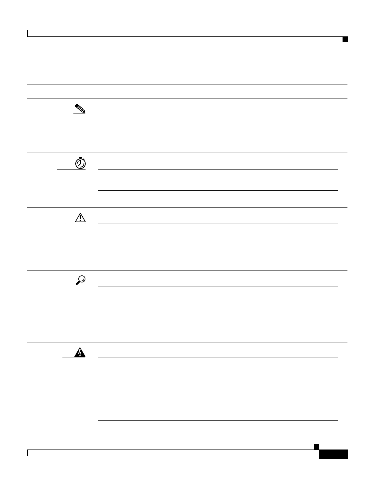
Note This symbol means reader ta ke note. Notes contain helpful
suggestions or referen ces to additional in for mation and m aterial.
Timesaver This symbol means the described action sav es tim e. You can save
time by performin g the acti on descri bed in the p aragra ph.
Conventions
Caution This symbol means re ader be careful. In this situation, you might
do something that could result in equipment damage or loss of
data.
Tips This symbol means the following information will he lp you solve a
problem. The tips information might not be troubl eshoot ing or
even an action, but could be useful information, similar to a
Timesaver.
Warning
This warning symbol means danger. You are in a situation that
could cause bodily injury. Before you work on any equipment, be
aware of the hazards involved with electrical circuitry and be
familiar with standard practices for preventing accidents. T o see
translations of the warnings that appear in this publication, refer
to the Regulatory Compliance and Safety Information document
that accompanied this device.
OL-1267-01
Cisco ATA 186 Installation and Configuration Guide
xiii
Page 14

Conventions
Table 1 Conventions (continued)
Convention Description
Preface
Waarschuwing
Varoitus
Attention
Dit waarschuwingssymbool betekent gevaar. U verkeert in een
situatie die lichamelijk letsel kan veroorzaken. Voordat u aan
enige apparatuur gaat werken, dient u zich bewust te zijn van de
bij elektrische schakelingen betrokken risico's en dient u op de
hoogte te zijn van standaard maatregelen om ongelukken te
voorkomen. Voor vertalingen van de waarschuwingen die in deze
publicatie verschijnen, kunt u het document Regulatory
Compliance and Safety Information (Informatie over naleving van
veiligheids- en andere voorschriften) raadplegen dat bij dit toestel
is ingesloten.
Tämä varoitusmerkki merkitsee vaaraa. Olet tilanteessa, joka voi
johtaa ruumiinvammaan. Ennen kuin työskentelet minkään
laitteiston parissa, ota selvää sähkökytkentöihin liitt yvistä
vaaroista ja tavanomaisista onnet tomuuksien ehkäisykeinoist a.
Tässä julkaisussa esiintyvien varoitusten käännökset löydät
laitteen mukana olevasta Regulatory Compliance and Safety
Information -kirjasesta (määräysten noudattaminen ja tietoa
turvallisuudesta).
Ce symbole d'avertissement indique un danger. Vous vous trouvez
dans une situation pouvant causer des blessures ou des
dommages corporels. Avant de travailler sur un équipeme nt, soyez
conscient des dangers posés par les circuits électriques et
familiarisez-vous avec les procédures couramment utilisées pour
éviter les accidents. Pour prendre connaissance des traductions
d’avertissements figurant dans cette publication, consultez le
document Regulatory Compliance and Safety Information
(Conformité aux règlements et consignes de sécurité) qui
accompagne cet appareil.
Cisco ATA 186 Installation and Configuration Guide
xiv
OL-1267-01
Page 15

Preface
Table 1 Conventions (continued)
Convention Description
Conventions
Warnung
Avvertenza
Advarsel
Dieses Warnsymbol bedeutet Gefahr. Sie befinden sich in einer
Situation, die zu einer Körperverletzung führen könnte. Bevor Sie
mit der Arbeit an irgendeinem Gerät beginnen, seien Sie sich der
mit elektrischen Stromkreisen verbundenen Gefahren und der
Standardpraktiken zur Vermeidung von Unfällen bewußt.
Übersetzungen der in dieser Veröffentlichung enthaltenen
Warnhinweise finden Sie im Dokument Regulatory Compliance
and Safety Information (Informationen zu behördlichen
Vorschriften und Sicherheit), das zusammen mit diesem Gerät
geliefert wurde.
Questo simbolo di avvertenza indica un pericolo. La situazione
potrebbe causare infortuni alle persone. Prima di lavorare su
qualsiasi apparecchiatura, occorre conoscere i pericoli relativi ai
circuiti elettrici ed essere al corrente delle pratiche standard per
la prevenzione di incidenti. La traduzione delle avvertenze
riportate in questa pubblicazione si trova nel documento
Regulatory Compliance and Safety Information (Conformità alle
norme e informazioni sulla sicurezza) che accompagna questo
dispositivo.
Dette varselsymbolet betyr fare. Du befinner deg i en situasjon
som kan føre til personskade. Før du utfører arbeid på utstyr , må du
vare oppmerksom på de faremomentene som elektriske kretser
innebærer , samt gjøre deg kjent med vanlig praksis når det gjelder
å unngå ulykker . Hvis du vil se oversettelser av de advarslene som
finnes i denne publikasjonen, kan du se i dokumentet Regulatory
Compliance and Safety Information (Overholdelse av forskrifter og
sikkerhetsinformasjon) som ble levert med denne enheten.
OL-1267-01
Cisco ATA 186 Installation and Configuration Guide
xv
Page 16

Obtaining Documentation
Table 1 Conventions (continued)
Convention Description
Preface
Aviso
¡Advertencia!
Varning!
Este símbolo de aviso indica perigo. Encontra-se numa situação
que lhe poderá causar danos físicos. Antes de começar a trabalhar
com qualquer equipamento, familiarize-se com os perigos
relacionados com circuitos eléctricos, e com quaisquer práticas
comuns que possam prevenir possíveis acidentes. Para ver as
traduções dos avisos que constam desta publicação, consulte o
documento Regulatory Compliance and Safety Information
(Informação de Segurança e Disposições Reguladoras) que
acompanha este dispositivo.
Este símbolo de aviso significa peligro. Existe riesgo para su
integridad física. Antes de manipular cualquier equipo,
considerar los riesgos que entraña la corriente eléctrica y
familiarizarse con los procedimientos estándar de prevención de
accidentes. Para ver una traducción de las advertencias que
aparecen en esta publicación, consultar el documento titulado
Regulatory Compliance and Safety Information (Información sobre
seguridad y conformidad con las disposiciones reglamentarias)
que se acompaña con este dispositivo.
Denna varningssymbol signalerar fara. Du befinner dig i en
situation som kan leda till personskada. Innan du utför arbete på
någon utrustning måste du vara medveten om farorna med
elkretsar och känna till vanligt förfarande för att förebygga
skador. Se förklaringar av de varningar som förkommer i denna
publikation i dokumentet Regulatory Compliance and Safety
Information (Efterrättelse av föreskrifter och
säkerhetsinformation), vilket medföljer denna anordning.
Obtaining Documentation
The following sections provide sources for obtaining documentation from Cisco
Systems.
Cisco ATA 186 Installation and Configuration Guide
xvi
OL-1267-01
Page 17

Preface
World Wide Web
You can access the most current Cisco do cumentation on the World Wide Web at
the following sites:
• http://www.cisco.com
• http://www-china.cisco.com
• http://www-europe.cisco.com
Ordering Documentation
Cisco documentation is available in the following ways:
• Registered Cisco Direct Cu stome rs c an or der Ci sco Pr oduct doc ument ati on
from the Networking Products MarketPlace:
Obtaining Documentation
http://www.cisco.com/cgi-bin/order/order_root.pl
• Registered Cisco.com users can orde r the Document ation CD-ROM through
the online Subscriptio n Stor e:
http://www.cisco.com/go/subscription
• Nonregistered Cisco.com users can orde r documen tation thro ugh a loca l
account represent ative by calling Cisco corp orate he adquar ters (Cal ifornia ,
USA) at 408 526 -72 08 or, in North A meri ca, by c alling 80 0
553-NETS(6387 ).
Documentation Feedback
If you are reading Cisco product documentation on the World W ide Web, you can
submit technical comments electronically. Click Feedback in the toolbar and
select Documentation. After you complete the form, click Submit to send it to
Cisco.
You can e-mai l your comm ents t o bug-doc@c isco.com.
To s ubm it your co mme nts by mai l, u se the resp onse ca rd be hind t he f ro nt c over
of your document, or wri te to the foll owing address:
OL-1267-01
Cisco ATA 186 Installation and Configuration Guide
xvii
Page 18

Obtaining Technical Assistance
Attn Document Resour ce Conn ection
Cisco Systems, Inc.
170 West Tasman Drive
San Jose, CA 951 34- 988 3
We ap prec iate yo ur comm ents .
Obtaining Technical Ass istance
Cisco provides Cisco.com as a starting point for all technical assistance.
Customers and p art ners ca n obt ain do cume ntat ion, trou ble shoo tin g tips, a nd
sample configurations from online tools. For Cisco.com registered users,
additional tro uble shoo tin g to ol s are available fr om the Technical Assistanc e
Center (TAC) website.
Preface
Cisco.com
Cisco.com is the found ation of a suite of inter active, networked service s that
provides immediate, open access to Cisco information and resources at anytime,
from anywhere in the world. This highly integrated Internet application is a
powerful, easy-to-use tool for doing business with C isco.
Cisco.com provides a broad range of features and services to help customers and
partners stream line business p roce sses a nd impr ove productivity. Through
Cisco.com, you c an find info rm ation a bou t Cisc o and o ur net working s ol uti ons,
services, and progra ms. In addi tion, you c an reso lve technic al issue s with on lin e
technical support, download and test software packages, and order Cisco learning
materials and merchandise. Valuable online skill assessment, training, and
certification programs are also available.
Cisco ATA 186 Installation and Configuration Guide
xviii
OL-1267-01
Page 19

Preface
Customers and partners can self-register on Cisco.com to obtain additional
personalized information and services. Registered users can order products, check
on the status o f an or de r, access techn i cal suppor t , an d v iew benefits sp ec ific to
their relationships with Cisco.
To access Cisco.com, go to the following website:
http://www.cisco.com
Technical Assistance Center
The Cisco TAC website is available to all customers who need technical
assistance with a Cis co produ ct or techno logy that i s under warra nty or covered
by a maintenance co ntra ct.
Obtaining Technical Assistance
Contacting TAC by Using the Cisco TAC Website
If you have a priorit y l evel 3 (P3) or pr io rity l evel 4 (P4) prob lem , con tac t TAC
by going to the TAC websi te:
http://www.cisco.com/tac
P3 and P4 level problems are defined as follows:
• P3—Your network performance is degraded. Network functionality is
noticeably impaired, but most bu siness operations continue.
• P4—You need information or assistance on Cisco product capabilities,
product installation , or basic produc t configurati on.
In each of the above cases, use the Cisco TAC website to quickly find answers to
your questions.
To register for Cisco.com, go to the following website:
http://www.cisco.com/register/
If you cannot resolve your technical issue by using the TAC online resources,
Cisco.com registered users can ope n a case online by using the TAC Case Open
tool at the following websi te:
http://www.cisco.com/tac/caseopen
OL-1267-01
Cisco ATA 186 Installation and Configuration Guide
xix
Page 20

Product Disposal Warning
Contacting TAC by Telephone
If you have a priorit y l evel 1 (P1) or pr io rity l evel 2 (P2) prob lem , con tac t TAC
by telephone and immedia tely open a cas e. To obtain a directory of toll-free
numbers for your count ry, go to the following website:
http://www.cisco.com/warp/public/687/Directory/DirTAC.shtml
P1 and P2 level problems are defined as follows:
• P1—Your produ cti on net work i s down, ca using a cr itical im pa ct to busine ss
operations if servic e is not restor ed qui ckly. No workaround is available.
• P2—Your producti on network is severely degraded, affecting signi ficant
aspects of your business op erati ons. No workaround i s available.
Preface
Product Disposal Warning
Warning
Waarschuwing
Varoitus
Attention
Warnung
Ultimate disposal of this product should be handled according to
all national laws and regulati ons.
Het uiteindelijke wegruimen van dit product dient te geschieden
in overeenstemming met alle nationale wett en en reglementen.
Tämä tuote on hävitettävä kansallisten lakien ja määräysten
mukaisesti.
La mise au rebut ou le recyclage de ce produit sont généralement
soumis à des lois et/ou directives de respect de l'environnement.
Renseignez-vous auprès de l'organisme compétent.
Die Entsorgung dieses Produkts sollte gemäß allen
Bestimmungen und Gesetzen des Landes erfolgen.
Avvertenza
Cisco ATA 186 Installation and Configuration Guide
Lo smaltimento di questo prodotto deve essere eseguito secondo
le leggi e regolazioni locali.
xx
OL-1267-01
Page 21

Preface
Product Disposal Warning
Advarsel
Aviso
¡Advertencia!
Varning!
Endelig kassering av dette produktet skal være i henhold til alle
relevante nasjonale lover og bestemmelser.
Deitar fora este produto em conformidade com todas as leis e
regulamentos nacionais.
Al deshacerse por completo de este producto debe seguir todas
las leyes y reglamentos nacionales.
Vid deponering hanteras produkten enligt gällande lagar och
bestämmelser.
OL-1267-01
Cisco ATA 186 Installation and Configuration Guide
xxi
Page 22

Cisco ATA 186 Overview
This chapter p rovides an overview of the Cisc o ATA 186 An al og Telephone
Adaptor and descr ibes t he sy stem f eat ures.
About the Cisco ATA 186
The Cisco ATA 186:
• Is an Internet telephony appliance that converts any regular analog telephone
into an Internet telephone.
CHAPTER
1
OL-1267-01
• Converts voice into IP data packets that are sent over a network.
• Is installe d at the subs cr iber ’s premises.
• Supports two voice ports with their own telephone numb ers.
• Has one 10BaseT R J-45 po rt and two RJ-1 1 FXS sta nd ard ana log tele phone
ports.
• Supports both l ow-compl exity voice codec s, su ch as G.7 11µ , G.71 1A-l aw,
and high-complexit y/CELP co decs, such as G.723. 1 and G.729 A.
• Can be configured t o use e ithe r th e H.32 3 o r the SIP call sign ali ng prot ocol .
• Operates with Cisco Voice Packet Gateways.
• Operates with H.323- or SIP-compliant Voice Packet Gateways.
Cisco ATA 186 Installation and Configuration Guide
1-1
Page 23
Chapter1 CiscoATA 186 Overview
Hardware Featur es
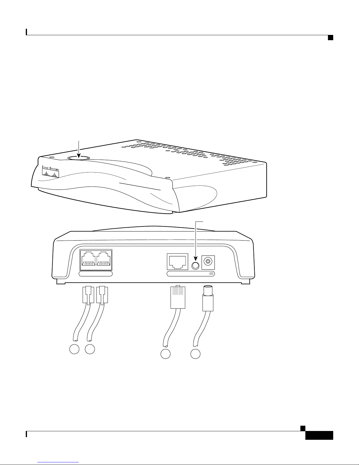
The Cisco A TA 186 features the hardware options listed in this section and shown
in Figure 1-1.
Figure 1-1 Features of the Cisco ATA 186
Function button
CISCO ATA 186
ANALOG TELEPHONE ADAPTOR
About the CiscoATA 186
Indicator LED
10BaseT ACT 5VPHONE 1 PHONE 2
A
B
62423
C D
A—Phone 1 conne ctor ( RJ-1 1)
B—Phone 2 connector (RJ- 11)
C—10Base-T Ethe rnet co nnec tor
D—12V power connector
OL-1267-01
Cisco ATA 186 Installation and Configuration Guide
1-2
Page 24

About the Cisco ATA 186
• Dual RJ-11 Ports
–
Supports two independent RJ-11 telephone ports that can connect to any
standard anal og te lephon e device. Eac h port s uppor ts eith er voice ca lls
or FAX sessions, so t hat the us er c an t al k on one p ort whi le sendi ng a
FAX on t he other.
–
There are two RJ-11 FXS port terminating impedance options, 600 Ohms
resistive or 270 Ohms + 7 50 O hms // 15 0 nF c ompl ex imp edan ce. Th e
impedance of t he Cisco ATA 186 d epend s o n th e opt ion orde re d an d
must match the particular application. If you are not sure of the
applicable configuration, check the country or regional telephone
impedance requi reme nts.
• Indicators
–
Function Button
The Cisco ATA 186 functi on button is located in the top panel of t he
device. The funct ion button l ights w hen you pi ck u p the ha ndset o f a
telephone atta che d to t he C isco ATA 186. When th e fu nct ion button
blinks, the device i s in c on figurati on searc h or up gra de mod e. You also
use the function button to acce ss the inter active voice response (IVR )
configuration m enu. To configure the Cisco ATA 18 6 by u sin g th e IVR
mode, see Cha pter 3, “Co nfiguring the Cisc o ATA 186.”
Chapter 1 Cisco ATA 186 Overview
Additional Feature
Cisco ATA 186 Installation and Configuration Guide
1-3
–
Activity LED
The green Activity LED located on the back panel flashes to indicate
network activity.
• 5 Volt power adapter connector (adapter included)
• 10Base-T Ethe rnet port
Supports polarity reversal before and after calle r-ID signal.
OL-1267-01
Page 25

Chapter1 CiscoATA 186 Overview
About the CiscoATA 186
Software F ea tures
Features of the Cisco ATA 186 de pend on the prot ocol use d.
General Features
Table 1-1 includes informa tion on fe atu res tha t a re available fo r al l p rotoc ols.
Table 1-1 Features Available for all Signaling Protocols
Description Details
Basic provisioning (TFTP Profiling) API, profile generation, client provisioni ng, RC4
encryption, a nd hard key
Call forwardi ng always fr om t he Ci sco ATA 1 86
Call forwar ding on no answ er fro m t h e
Cisco ATA 186
Call forwarding on busy from the Cisco ATA 186
Call waiting
Calling Line ID Presentation (CLIP)
Calling Line ID Rejection (CLIR)
Comfort noise generation (CNG)
Configurable ring specification
Dial Plan Suppor t Feature access co de suppor t
Domain Name Server (DNS) Lookup
DTMF Caller ID On-hook only
Dynamic Jitter Buffering
Fax Detect/Passthrough
Note Limited fax passth rou gh supp ort i s
available (up to 9.6 kbps fax
transmission rates for mos t fax
machines). Ex tend ed su ppor t is
planned. Please check release notes
and product bulletins for updates.
G.711, Codec re-negotiation
OL-1267-01
Cisco ATA 186 Installation and Configuration Guide
1-4
Page 26

Chapter 1 Cisco ATA 186 Overview
About the Cisco ATA 186
Table 1-1 Features Available for all Signaling Protocols
Description Details
Frequency Shift Key (FSK) Caller ID On-hook only
Line-echo cancellation 8 ms fixed echo length setting
Local ring-back tone
Remote diagnost ics/moni tor (tr ace of execution)
Three-way calling (conferencing) The Cisco ATA 186 will automatically switch to
G.711 in this mode.
Type of Service (TOS) bit for Quality of Service
(QOS)
Vo ice activity detection (VAD)
H.323-specific Features
Table 1-2 H.323-specific Features
Description Details
Alternate gatekeeper
Call proceeding
Cisco registration- a nd ad mi ssion -level securit y
support
Dual Tone Multiple Frequency (DTMF) relay H.245
Empty cap s et
Fast start/tunneling/earl y H. 245 Including H.245 me ssage s in the Ale rt m essage
Uses MD5 hashing
Uses access/clear token
Cisco ATA 186 Installation and Configuration Guide
1-5
OL-1267-01
Page 27

Chapter1 CiscoATA 186 Overview
About the CiscoATA 186
SIP Specific Features
Table 1-3 SIP Features
Description Details
Authen ti c a ti o n Digest A u th enticati o n
DTMF Relay RFC 2833
Call Forwarding Unconditional ly, on no answer, or on busy
Call Return
Call Transfer With or without co nsulta tio n
Message Waitin g Indication (MWI) P lays an inter mittent d ial tone if there is a message
waiting. Otherwi se , pl ay s a n orm al di al tone .
Third-party call control
OL-1267-01
Cisco ATA 186 Installation and Configuration Guide
1-6
Page 28

Chapter 1 Cisco ATA 186 Overview
About Supported Standards and Protocols
About Supported Standards and Protocols
The following standa rd s are su ppo rte d on t h e Cisco ATA 18 6:
• Network interface: one RJ-45 8- wire co nnecto r, IEEE 802.3 10Base-T
standard
• Two RJ-11 FXS standard anal og teleph one voice ports, up to 5 ri nger
equivalency number (REN) per port, depend ing on loop len gth
• ITU G.711µ, G.711 A, G.723.1 Annex A, and G.729 A nnex A voice codecs
• G.723.1 Annex A, voice activity detection (VAD) /comfo rt noise gene ration
(CNG): bandwidth saving algorith m
• ITU H.323 V.2 call signaling protocol
• SIP: RFC 2543bis
• LSSGR: Signaling for analog interfaces GR-506-CORE
• RT P: real-time transmission Internet protocol
• ITU-T V.42/V.42bis and MN P2-10 erro r corre ction and data comp ression
• AVT Tones: RFC 2833
• DHCP: RFC 2131
Cisco ATA 186 Installation and Configuration Guide
1-7
OL-1267-01
Page 29

Chapter1 CiscoATA 186 Overview
Electrical Specifications
Table 1-4 Electrical Specifications
Category Specification
Voltage +5.0 VDC at 1.5 A maximum
Power 0.25 to 7.5 Watts (idle, maximum )
Power adaptor Universal AC/DC
About Supported Standards and Protocols
3.3 x 2.0 x 1.3 in (~ 8.5 x 5. 0 x 3 .2 c m)
4.8 oz (13 5 g m) for th e AC-input extern al power
adaptor
4 ft (1.2 m) DC c ord
Environmental Specifications
Table 1-5 Environmental Specifications
Category Specification
Operating Temperature 32° to 122° F (0 to 5 0° C )
Storage Temperature -22° to 149° F (-3 0° to 65 ° C)
Relative Humidity 10 to 90% non-condensing , operat ing and stora ge
Class II transformer
6 ft (1.8 m) co rd
UL/CUL, CE agency ap provals
OL-1267-01
Cisco ATA 186 Installation and Configuration Guide
1-8
Page 30

About Supported Standards and Protocols
Standards Compliance
Table 1-6 Standards Compl ianc e
Category Specification
Agency approvals UL/C-UL
Safety standards UL609 50
Chapter 1 Cisco ATA 186 Overview
FCC (Declaration of Conformity) Class B part 15 and part
68.
European Un ion, CE m ark (D ecla ra tio n of Conf or mit y)
Industry Canada (De clarat ion of Confo rmity )
ACA (Declaration of Conformity)
VCCI (Declara tion of Conf ormit y)
CAN/CSA-C22.2 No. 609 50-00
IEC 60950 (Second Edition with Amendments 1, 2, 3, and
4)
EN60950:1992 (w ith Ame ndments 1, 2, 3, 4, and 11)
AS/NZS 3260:19 93 (with Am endme nts 1, 2, 3, an d 4)
TS001:1997
Cisco ATA 186 Installation and Configuration Guide
1-9
OL-1267-01
Page 31

Chapter1 CiscoATA 186 Overview
Table 1-6 Standards Compl ianc e
Category Specification
Emissions CFR 47 Part 15 Class B 2000
Immunity EN50082-1 inclu ding the following
About Supported Standards and Protocols
EN55024, EN500 82- 1
EN55022/CISPR22 Cla ss B
VCCI Class B
AS/NZS 3548:1995 Cl ass B
ICES-003 (Issue 2, Cla ss B , April 1 997 )
EN61000-3-2, Electromagnetic Compatibility
EN61000-3-3, Electromagnetic Compatibility
Dimensions
EN61000-4-2, ESD
EN61000-4-3, Ra diated Im muni ty
EN61000-4-4, Bur st Transients
EN61000-4-5, Surge
EN61000-4-6, In jected RF
EN61000-4-11, Dips an d Sa gs
Table 1-7 Dimensions
Category Specification
Length 6.5 in (16.5 cm)
Width 6 in (15.25 cm)
Height 1.5 in (3.8 cm)
We ight 1 5 oz (425 gm)
OL-1267-01
Cisco ATA 186 Installation and Configuration Guide
1-10
Page 32

About Supported Standards and Protocols
Chapter 1 Cisco ATA 186 Overview
Cisco ATA 186 Installation and Configuration Guide
1-11
OL-1267-01
Page 33

Installing the Cisco ATA 186
This chapter provid es information about installing the Cisco ATA 186.
English is the default lan guage. For infor mation on t he upgrade process, see
Chapter 6, “Upgrading the Cisco ATA 186 Software.”
Installation Overview
The general steps necessary to install the Cisco ATA 186 are:
1. Plan the network an d C isco ATA 186 c onfigurati on .
CHAPTER
2
OL-1267-01
2. Install the Ethernet connection.
3. Install and c onfigure the oth er ne twor k d evices; f or example, ga tekeepe r if
you are using H .323 o r pro xy ser ver if y ou are usi ng SIP.
4. If you will be routing calls through the Public Switched Telephone Network
(PSTN), install and configure the Gateway.
5. Install the Cisco ATA 186.
6. Configure the Cisco ATA 186.
7. Perform any troubleshooti ng and main tenance , including up grading the
software if necessary.
Cisco ATA 186 Installation and Configuration Guide
2-1
Page 34

Installation Overv iew
Figure 2-1 shows an example of a network with a Cisco ATA 186.
Figure 2-1 Example Network Diagram
Chapter 2 Installing the Cisco ATA 186
Gatekeeper
or Proxy Server
10BaseT ACT 5VPHONE 1 PHONE 2
ATA 186
Broadband
modem
ISP
Connection
POP
IP
Network
PSTN
Voice
Gateway
62467
Cisco ATA 186 Installation and Configuration Guide
2-2
OL-1267-01
Page 35

Chapter 2 Installing the Cisc o ATA 186
Network Requirements
The Cisco ATA 18 6 ac ts a s a t erm in al on a n I P n etwork. You need the following
equipment:
• One or two stan da rd an al og tel ep hone ha ndset s.
• Ethernet conne ctio n.
• Gatekeeper or pro xy server— Current ly, there must be a device running ITU
H.323 or RFC 2543bis SIP-compla int software. The gatekeepe r must be
running the a pplic a ble version of sof t ware fo r t he fe atu re s and pr otoc ol y ou
want to us e .
• Voice Packet Gateway—Required if you are connecting to the Public
Switched Telephone Network (PSTN).
• Fax machine (optional).
Network Requirements
• If you are using a firewall, Cisco recommends that it be a Cisco PIX firewall,
Version 5 or later versions.
Safety Recommendations
To ensure general safety, follow these guidelines:
• Do not open or disassemble this product.
• Do not get this product wet or pour liquids into this device.
• Do not perform any action that creates a potential hazard to people or makes
the equipment u nsafe .
OL-1267-01
Cisco ATA 186 Installation and Configuration Guide
2-3
Page 36

System Requirements
System Requirements
Caution The Cisco ATA 186 is int ended for use with a 5V DC power adaptor only.
The Cisco ATA 186 installation package includes:
• Cisco ATA 186
• Cisco ATA 186 documentation
• 5V Power Adaptor
You also need:
• 10BaseT category-3 c abl e or be tte r
• One or two an alo g to uch -t on e t elepho ne s
Chapter 2 Installing the Cisco ATA 186
Note Telephones must be set to use tone, rather than pulse dialing for the
Cisco ATA 186 to operat e c or rectl y.
Cisco ATA 186 Installation and Configuration Guide
2-4
OL-1267-01
Page 37

Chapter 2 Installing the Cisc o ATA 186
Installation Warnings
This section c onta ins impor tan t sa fet y inf orma tio n.
Number 26 AWG Warning
Installation Warnings
Warning
Waarschuwing
Varoitus
Attention
Warnung
Avvertenza
Advarsel
To reduce the risk of fire, use only No. 26 AWG or larger
telecommunication line cord.
Om brandgevaar te reduceren, dient slechts
telecommunicatielijnsnoer nr. 26 AWG of groter gebruikt te worden.
Tu lipalovaaran vähentämiseksi käytä ainoastaan nro 26 AWG- tai
paksumpaa tietoliikennejohdinta.
Pour réduire le risque d’incendie, n’utiliser que des cordons de
lignes de télécommunications de type AWG nº 26 ou plus larges.
Zur Reduzierung der Feuergefahr eine Fernmeldeleitungsschnur der
Größe 26 AWG oder größer verwenden.
Per ridurre il rischio di incendio, usare solo un cavo per linea di
telecomunicazioni di sezione 0,12 mm
Bruk kun AWG nr. 26 eller telekommunikasjonsledninger med større
dimensjon for å redusere faren for brann.
2
(26 AWG) o maggiore.
Aviso
¡Advertencia!
Varning!
OL-1267-01
Para reduzir o risco de incêndio, utilize apenas terminais de fio de
telecomunicações Nº. 26 AWG ou superiores.
Para reducir el riesgo de incendios, usar sólo líneas de
telecomunicaciones de calibre No. 26 AWG o más gruesas.
För att minska brandrisken skall endast Nr. 26 AWG eller större
telekommunikationsledning användas.
Cisco ATA 186 Installation and Configuration Guide
2-5
Page 38

Installation Warnings
Short-Circuit Protection Warning
Chapter 2 Installing the Cisco ATA 186
Warning
Waarschuwing
Varoitus
This product relies on the building's installation for short-circuit
(overcurrent) protection. Ensure that a fuse or circuit breaker no
larger than 120VAC, 20A U.S. (240VAC, 16 to 20A international) is
used on the phase conductors (all current-carrying conductors).
The fuse or circuit breaker must have adequate safety approvals
recognized by the country of usage.
Dit product is afhankelijk van de installatie van het gebouw voor
bescherming tegen kortsluiting (overstroom). Zorg ervoor dat de
zekering of stroomonderbreker die gebruikt wordt niet groter is
dan 120 V~, 20 ampère in de V.S. of 240 V~, 16-20 ampère
internationaal op de fasegeleiders (alle stroomdragende
geleiders). De zekering of stroomonderbreker dient de juiste
veiligheidsgoedkeuringen te hebben in het land waarin het
gebruikt wordt.
Tämä tuote on riippuvainen rakennuksen oikosulkusuojauksesta
(ylivirtasuojauksesta). Varmista, että vaihejohti missa (kaikissa
jännitteellisissä johtimis sa) käytet ään al le 240 V vaihtovirran,
16–20 ampeerin (kansainvälinen) tai 120 V vaihtovirran, 20
ampeerin (Yhdy svallat) sulaketta tai virtakytkintä. Sulakkeessa tai
virtakytkimessä on oltava käyttömaassa tunnistetut, riittävät
turvahyväksynnät.
Attention
Pour la protection contre les courts-circuits (surtension), ce
produit utilise les dispositifs intégrés au bâtiment. Assurez-vous
qu'un fusible ou un disjoncteur est utilisé sur les conducteurs de
phase (tous les conducteurs porteurs de courant). Le fusible ou le
disjoncteur (maximum 240 V CA, 16 à 20 A [aux USA, maximum 120
V CA, 20 A]) doit être conforme aux normes de sécurité en vigueur
dans votre pays.
Cisco ATA 186 Installation and Configuration Guide
2-6
OL-1267-01
Page 39

Chapter 2 Installing the Cisc o ATA 186
Installation Warnings
Warnung
Avvertenza
Advarsel
Diese Produkt erfordert eine Gebäudeabsicherung gegen
Kurzschluß (Überstrom). Achten Sie darauf, daß auf den
Phasenleitern (allen stromführenden Leitern) eine Sicherung oder
ein Schaltkreisunterbrecher verwendet wird, der nicht größer ist
als 120VAC, 20A U.S. (240VAC, 16 bis 20A international). Die
Sicherung oder der Schaltkreisunterbrecher muß angemessenen
Sicherheitsvorschriften genügen, die den Bestimmungen des
Anwendungslandes entsprechen.
La protezione di questo prodotto da cortocircuiti (sovracorrente)
dipende dall'impianto elettrico dell’edificio. Assicuratevi che un
fusibile o interruttore di circuito con meno di 120VAC, 20A U.S.
(240VAC, da 16 a 20A internazionale) venga utilizzato sui conduttori
di fase (tutti i conduttori di corrente elettrica). Il fusibile o
interruttore di circuito deve rispondere alle specifiche di
sicurezza invigore nel paese dove viene utilizzato.
Dette produktet er avhengig av bygningens installasjoner for
overstrømsbeskyttelse (kortslutning). Kontroller at det ikke brukes
en sikring eller overbelastningsbryter som er større enn 120 V, 20
ampere i USA, eller 240 V, 16 til 20 ampere internasjonalt, på
faselederne (alle strømførende ledere). Sikringen eller
overbelastningsbryteren må være sikkerhetsgodkjent i det
aktuelle landet der den skal brukes.
OL-1267-01
Aviso
Este dispositivo depende das instalações existentes para
protecção contra curto-circuitos (sobrecarga). Assegure-se de
que utiliza um fusível ou um disj untor com uma capacidade não
superior a 120VAC, 20A U.S. (240VAC, 16 a 20A internacional) nos
condutores de fase (todos os condutores de corrente). O fusível ou
disjuntor deverá possuir as necessárias aprovações de segurança
por parte das autoridades locais.
Cisco ATA 186 Installation and Configuration Guide
2-7
Page 40

Installation Warnings
Chapter 2 Installing the Cisco ATA 186
¡Advertencia!
Este producto ha sido diseñado teniendo en cuenta que la
instalación del edificio contará con protección contra
cortocircuitos (sobrevoltajes). Asegúrese de que se usa un fusible
o cortacircuitos no superior a 120VAC, 20A en los EE.UU. (240VAC,
de 16 a 20A en el resto de países) en los conductores de fase (todos
los conductores de transporte corriente). El fusible o
cortacircuitos debe contar con las aprobaciones de seguridad
adecuadas y reconocidas por el país en el que vayan a usarse.
Varning!
Denna produkt förlitar sig på att byggnadens installation är försedd
med skydd mot kortslutning (överström). Se till att en säkring eller
ett överspänningsskydd för högst 120 V~, 20 A USA (240 V~, 16 – 20
A internationellt) används på fasledarna (alla strömförande
ledare). Säkringen eller överspänningsskyddet måste ha fullgoda
säkerhetstillstånd som erkänns av användningslandet.
TN Power Systems Warning
Warning
Waarschuwing
Varoitus
Attention
Warnung
Avvertenza
2-8
The device is designed to work with TN power systems.
Het apparaat is ontworpen om te functioneren met TN
energiesystemen.
Koje on suunniteltu toimimaan TN-sähkövoimajärjestelmien
yhteydessä.
Ce dispositif a été conçu pour fonctionner avec des systèmes
d'alimentation TN.
Das Gerät ist für die Verwendung mit TN-Stromsystemen ausgelegt.
Il dispositivo è stato progettato per l’uso con sistemi di
alimentazione TN.
Cisco ATA 186 Installation and Configuration Guide
OL-1267-01
Page 41

Chapter 2 Installing the Cisc o ATA 186
Installation Warnings
Advarsel
Aviso
¡Advertencia!
Utstyret er utfomet til bruk med TN-strømsystemer.
O dispositivo foi criado para operar com sistemas de corrente TN.
El equipo está diseñado para trabajar con sistemas de alimentación
tipo TN.
Varning!
Enheten är konstruerad för användning tillsammans med
elkraftssystem av TN-typ.
Installing the Cisco ATA 186
Follow these steps to install the Cisco ATA 186 hardware. (See Figure 2-2.)
Figure 2-2 Installing the Cisco ATA 186
OL-1267-01
10BaseT ACT 5VPHONE 1 PHONE 2
62290
A
B
C D
Cisco ATA 186 Installation and Configuration Guide
2-9
Page 42

Installation Warnings
Step 1 Place the Cisco ATA 186 near an electrical outlet. Connect the first telephone to
Caution Do not connect the Cisco ATA 186 PHONE input ports to the telephone wall
Chapter 2 Installing the Cisco ATA 186
A—Phone 1 conne ctor ( RJ-1 1)
B—Phone 2 connector (RJ- 11)
C—10Base-T Ethe rnet co nnec tor
D—12V power connector
the PHONE 1 inp ut p ort (A) on the rea r pa nel of t he C is co ATA 186 by using a
telephone line cord with an RJ-1 1 con nector. The PHONE 1 input port wi ll be the
primary telepho ne line .
jack. To prevent damage to the device or building telephone wiring, con nect
each Cisco ATA 186 PHONE port to a telephone only, never to a telephone
wall jack.
Step 2 You can connect a second tele pho ne to th e PHONE 2 in put ( B) by using a second
telephone line cord. The PHONE 2 input is the secondary telephone line.
Note If you are connecting only one telephone to the Cisco A TA 186, you must use
the PHONE 1 input; otherwise, the telephone cannot place calls.
Step 3 Connect one end of a 10-BaseT Ethernet cable (C) to a hub, switch, or broadband
modem (DSL, c abl e, a nd so on).
Step 4 Connect the other end of the Ethernet cable to the RJ-45 input port (C) on the rear
panel of the C isco ATA 186 .
Note Use a crossover E ther net cab le to con ne ct t h e Ci sco ATA 18 6 to a nothe r
Ethernet device (such as a rout er or PC) with out using a hub. Otherwise, use
a straight through Eth ernet c able.
Step 5 Plug the A C po w er adap tor in to an ele ctrica l outlet. Insert the power cord into the
rear panel of the unit (D). Each connected telephone should ring once, indicating
that the Cisco ATA 186 is powered and ready to use. When the Cisco ATA 186 is
properly connected and powered up, t he green activity LED flashes. The ac tivity
LED, labeled ACT, indicates network activity.
Cisco ATA 186 Installation and Configuration Guide
2-10
OL-1267-01
Page 43

Chapter 2 Installing the Cisc o ATA 186
Caution To prevent overheating dur ing ope rat ion, do no t c over or bl ock th e ai r vents
in the top panel of the Cisco ATA 186.
If installation was successful, pr oceed to Chapter 3, “Configuring the
Cisco ATA 18 6.”
Verifying the Installation
If the phone do es not r ing a nd the func tion button does no t fl ash a fte r p ower-up,
check that the p ower ada pto r i s p lugge d int o a work i ng e l ectr i cal out let and t hat
the power cord is pushed securel y into the connector. Additionally, verify that the
Ethernet conne ction is se cure .
Installation Warnings
OL-1267-01
Cisco ATA 186 Installation and Configuration Guide
2-11
Page 44

Installation Warnings
Chapter 2 Installing the Cisco ATA 186
Cisco ATA 186 Installation and Configuration Guide
2-12
OL-1267-01
Page 45

Configuring the Cisco ATA 186
This chapter provides i nforma tion about configurin g the Cisco ATA 186.
There are thr ee wa ys t o co nfigure y our Ci sco ATA 1 86:
• Voice Configuration Menu
• Web br owser
• Autoprovisioning
Configuration Requirements
CHAPTER
3
OL-1267-01
The Cisco ATA 186 requires the following minimum settings for network
connectivity:
• IP address
• Network route address (I P gateway)
• Subnet mask
Note To ente r an IP address, pre ss the * key to indicate a delim iter (dot ). For
example,
your Cisco ATA 186 h as be en insta lled c orrec tl y, lift the teleph one h an dset
and enter 21#.
192*168*3*1. To hear th e IP ad dre ss o f your C is co ATA 186 , after
Cisco ATA 186 Installation and Configuration Guide
3-1
Page 46

Chapter 3 Configuring the Cisco ATA 186
About Using the Voice Conf ig uration Menu
These settings are automatically configured in a DHCP network. When the
Cisco ATA 186 is downloading its DHCP con figuratio n or sof tware upg rade , the
function button on the top panel blinks.
Caution Do not unplug the device while the function button is blinking. Doing so can
cause permanent da mage to the device.
Note If there is no DHCP server and the Ci sco ATA 18 6 is program ed to find one,
the function button will keep blinking.
About Using the Voice Configuration Men u
Some IVR menu options will require you to enter alphanumerica characters.
Alphanumeric en try differs f rom n umeri c e ntr y in t hat yo u mu st en ter the # key
after each character selected. Using Table 3-1 as a guide, enter the appropriate
number key on your t el ephon e ha ndset a s m a ny times as ne ede d to se lect the
number, letter, or symbol you want. For example, to enter 58sQ, you would enter:
5 # 8 # 7 7 7 7 7 # 7 7 7 7 7 7 7 # #
If you need to enter a n alphanum eric v al ue, t he v oice pro mpt will sp ecif ically tell
you to enter an a lphanumeric value; otherwise, you sh ould enter a numer ic value
(0-9).
Cisco ATA 186 Installation and Configuration Guide
3-2
OL-1267-01
Page 47

Chapter 3 Configuring the Cisco ATA 186
Table 3-1 lists the keys and their respective alphanumeric characters.
.
Table 3-1 Alphanumeric Characters
Key Characters
1 1 ./_\ @@*space return +-!,?|~^ ##=$" '
2 2 a b c A B C
33 d e f D E F
4 4 g h i G H I
5 5 j k l J K L
66 m n o M N O
About Using the Voice Configuration Menu
``%<>[ ] ::;{}()&
77 p q r s P Q R S
88 t u v T U V
9 9 w x y z W X Y Z
00
* . (delimeter)
The voice will repeat the value you entered; then, prompt you to press one of the
following keys:
• 1=change yo ur ent ered value
• 2=review your entered value
• 3=save your entered value
• 4=review the current saved value
OL-1267-01
Cisco ATA 186 Installation and Configuration Guide
3-3
Page 48

Using the Web Configuration Page
Using the Voice Configuration Menu
To manually configure the Cisco ATA 186 by using the interactive voice
response (IVR) system and telephone keypad, follow the steps in this section. For
a list of the available configuration options, see Appendix A, “Voi ce Menu
Options.”
Step 1 Lift the handset and press the Function button located on top of the
Cisco ATA 18 6.
Step 2 Enter the IVR menu number for the parameter that you want to configure or the
command that you wa nt to execute; then , press the po und key (#). (See
Appendix A, “Voice Me nu Opti ons,” a nd Appe ndix B, “Paramete rs a nd
Defaults,” for lists of options and thei r corre spo ndin g m enu num bers. )
Step 3 Follow the applicable prompts.
Chapter 3 Configuring the Cisco ATA 186
Step 4 When you have finished, make sure you press 3 to save your changes.
Step 5 Hang up the telephone. The Cisco ATA 186 resets.he function button will
fast-blink when the reset is complete.
Using the Web Configurati on Page
You can configure you r Cisco ATA 186 by using the web configur ation page.
Each configurable parameter is listed, and parameters are grouped and
color-coded accord ing to thei r functi on.
Caution Cisco recommends you do not perform the initial configuration over the
Internet; the co nfiguration pa ge is not sec ure. Af ter you have configured the
parameters, password-protect the user interface to prevent it from being
accessed on the Inte rnet. Th e parame ter for passwor d-prote cting this page is
UIPasswd.
Follow these steps:
Cisco ATA 186 Installation and Configuration Guide
3-4
OL-1267-01
Page 49

Chapter 3 Configuring the Cisco ATA 186
Step 1 Make sure that the PC and th e Cisc o ATA 186 are alr eady networked a nd v isible
to one another.
Step 2 Open your web b rowser.
Step 3 Enter the URL o f your con figurat ion page . The UR L of t he w eb se rver is:
IP Address/dev
For example, the configuration page for a Cisco ATA 186 with t he IP address
192.168.3.225 is :
http://192.168.3.225/dev
See “Using the Web Con figurat ion Page” sect ion on pa ge 3-4 for informati on on
how to find the IP address of your Cisc o ATA 186.
Step 4 Select the values for the items that you want to configure. (See Appendix B,
“Parameters and Defaults,” for a list of options.) Scroll down to see all
parameters. Yo u can password -prote ct the user int erface for securi ty.
About Autoprovisioning
Step 5 Click apply to save your changes.
Step 6 Close your web b rowser.
About Autoprovisioning
For large-scale networks, you can use a TFTP server to host a profile for each
Cisco ATA 186. The TFTP ser ver's URL and file nam e can be provid ed
(provisioned) from th e DHCP server.
Set UseTFTP to 1.
TftpURL is the IP address of the TFTP server. If TftpURL is set to 0, the DHCP
server will supply the IP address.
Name the file to be downloaded according to the format:
ataxxxxxxxxxxxx
Each xx is the 2-digit lower case h exadecimal representation of each integer in the
MAC address of the Cisco ATA 186.
OL-1267-01
Cisco ATA 186 Installation and Configuration Guide
3-5
Page 50

About Autoprovis ion ing
Note If the ToConfig value is set to 1, the Cisco ATA 186 will contact the TFTP
Chapter 3 Configuring the Cisco ATA 186
For example, for a Cisco A TA 186 with a MAC address of 0.1.45.2.10.20, the file
name is:
ata00012D020A14
The filename has a fixed length of 15 cha ra cters , r egardless of the MAC address.
In this mode of provisioning, at power-up, the Cisco ATA 186 contacts the TFTP
server for a specific p rofile to download. The profile can be encrypted with a
shared secret key. If the Cisco ATA 186 does not reach the TFTP server after 3
attempts, it continues normal operation by using its locally cached profile.
server continuously without waiting until the next CfgInterval. The value for
CfgInterval is the value of CfgInterval in seconds.
At CfgInterval, the Cisco ATA 186 attempts to refresh its profile from the TFTP
server.
You can configure the Ci sco ATA 18 6 to refresh ea rlier th an the schedu led
CfgInterval by opening a r efr e sh we b page on the C isco ATA 186 . The refre sh
page is:
http://ipaddress/refresh
For example, for a Cisco ATA 186 whose IP address is 192.168.2.170, the refresh
page would be:
http://192.168.2.170/refresh
If you are using TFTP when the Cisco A TA 186 is plugged in, the Cisco A TA 186
will try to contact the TFTP server to download its configuration. This method is
not secure unless you are us ing Encry ptKey. See the “Encrypt Key” secti on on
page 3-8.
cfgfmt.exe and ptag.dat Files
Bundled with th e Cisco ATA 186 software is the program cfgfmt.exe and the file
ptag.dat. These should be placed the directory used to store the files for transfer
using TFTP. The cfgfmt program is used to convert a text-based user profile for
Cisco ATA 186 Installation and Configuration Guide
3-6
OL-1267-01
Page 51

Chapter 3 Configuring the Cisco ATA 186
the Cisco ATA 186 to a binary file sent by the TFTP server to the Cisco ATA 186
to update its configuratio n parameters. The cfgfmt.exe program is used with the
following syntax:
cfgfmt [-eRC4Password] [-tPTagFile] input output
• eRC4Password is the optional R C4 key to enc ryp t the bin ar y TF TP file
provided by the cf gfmt pr ogra m
• tPTagFile is the optional command used to specify a ptag file other than the
one provided (ptag.d at)
• input is the name of the text-based profile of the Cisco AT A 186 that will be
converted to a TFTP binary file
• output is the name of the TFTP bina ry file produced by the cfgfmt pro gram
About Profile and Configuration Security
Updating the Profile from the TFTP Server
To u pdat e t he C isc o ATA 186 profile from the TFT P se rver befo re the
CFGINTERVAL expires, open yo ur web br owser and ent er:
http://ipaddress/refresh
where ipaddress is the IP address of the Cisco ATA 186 y ou want to update. The
Cisco ATA 186 responds with an ok pa ge if idle; otherw ise, it re sponds with a
later page.
If you have physical acc ess to t he Ci sco ATA 186, y ou ca n power cycle t he
Cisco ATA 186 to update the pr ofile fro m TF TP se rver.
About Profile and Configuration Security
This section inc lude s in forma ti on on pa sswords and o ther sec urity me thod s.
Passwor ds
To p as sword-pr otec t y our Ci sco ATA 186:
OL-1267-01
Cisco ATA 186 Installation and Configuration Guide
3-7
Page 52

About Using the DHCP Server
Step 1 Set the UIPassword parameter to a numeric password by using the w eb server
Step 2 You will be prompted for a password when you try to access the web server or a
Encrypt Key
Chapter 3 Configuring the Cisco ATA 186
interface or TFTP profiling.
configurable IVR param eter.
• In web server mode, enter the password in the UIPassword field of the
password challenge pa ge.
• In IVR mode, enter the password, followed by the # key, at the p-a-s-s-w-d
prompt.
Encrypt Key encrypts binary files being tr ansferre d over TFTP. You can change
this key for eac h C isco ATA 186, s o t hat o nly one par tic ula r box c an d ec ode the
information. You can change the e ncryp t key, using the IVR or we b in te rface.
See the “cfgfmt.exe and ptag.dat Files” section for more information.
The Cisco ATA 186 polls the server at intervals set in CfgInterval to see if it
needs to be upgraded. You can customize this service. For example, you can route
all calls from a particular Cisco ATA 186, based on the Gatekeeper ID, to an
operator.
About Using the DHCP Server
DHCP option 60, DHCP_VENDOR_CLASS_ID, is set to the value ATA186 so
that the DHCP s erver can ide ntify a Cisco ATA 186.
Parameters that you can set using DHCP are:
• Client IP address
• Client Subnet mask—DHCP option 1
• Routers on the cl ient 's subn et— DH CP o ption 3
• Domain name servers—DHCP option 6
(The Cisco ATA 186 takes up to two DN S se rvers)
Cisco ATA 186 Installation and Configuration Guide
3-8
OL-1267-01
Page 53

Chapter 3 Configuring the Cisco ATA 186
• Network time protocol (NTP) servers—D HCP option 42
(The Cisco ATA 186 take s up to t wo NTP se rvers)
• TFTP server name—D HCP o pt ion 66
DNS, TFTP, and NTP servers can be overwritten by the value of the
correspondin g parame ters in the local box profile (for examp le, the DNS1I P,
DNS2IP, TftpURL, and NTPIP parameters).
If you are not using DHCP , you must manually enter the IP address, network route
address, and subnet mask.
About Using the DHCP Server
OL-1267-01
Cisco ATA 186 Installation and Configuration Guide
3-9
Page 54

Configuring Codec Op ti ons
Configuring Codec Options
You can configure th e various Codec ca ll optio ns for use w ith the
Cisco ATA 18 6.
Note The Cisco ATA 186 can support two simultaneous G.723 calls or one G.729A
call. When using G.729A, the second line must use G.711 u-law or a-law. The
default voice codec is G. 723 .
Step 1 To select G.723 as the preferred low-bit-rate codec (LBRCodec) for receive and
transmit modes, enter 0 into the LBC odec field on t he web page. To select
G.729A, enter 3.
Step 2 To s elect G.72 3 as the pr efer red re ceive codec (Rx Codec ) ent er 0 into the
RxCodec field on the we b p age. To select G.729A, ent er 3.
Chapter 3 Configuring the Cisco ATA 186
Step 3 To select G.723 as the preferred transmit codec (TxCodec), enter 0 into the
TxCodec field on the we b pa ge . To select G.729A, p ress 3.
Cisco ATA 186 Installation and Configuration Guide
3-10
OL-1267-01
Page 55

Protocol-Specific Configurations
This chapter contains i nformat ion on selec ting proto cols and servi ces for your
system.
About Signaling Protocols
You can select either H.323 or Session Initiation Protocol (SIP) as the operating
signaling protocol for the Cisco AT A 186. Both signaling protocols offer optional
network control servers. With H.323, pre-call and call control services are offered
by a gatekeeper , wh ile in SIP, a proxy server can r ece ive call transaction requests
and return responses on behalf of the Cisco ATA 186.
CHAPTER
4
Some parameters and sup pleme ntary ser vices ar e available with SIP, some are
available only with H.323, and others are available with bot h protoc ols.
About H.323-Specific Configurations
The Cisco ATA 186 u ses IT U H. 323, Version 2 as the default signa li ng pr otoc ol.
When operating in H.323 mode, the Cisco ATA 186 regi sters with a gatekeeper
to handle call control services. A full registration request (RRQ) is performed at
power-up. In order to let the gatekeeper know it is still on the network, the
Cisco ATA 186 periodically refres hes this registration by sending an abbreviated
RRQ. The value of the GKTimeToLive configuration parameter determines the
period betwee n re fr esh es, in se co nds.
Cisco ATA 186 Installation and Configuration Guide
OL-1267-01
4-1
Page 56

Chapter 4 Protocol-Specific Configurat ions
About Gatekeepe r Requirements for H. 323
To u se the H .323 se cu rity f e atur es, y ou mu st spec ify t he level of au th en tica tion
by means of the Au tMethod configuration parameter. The settings are as follows:
• 0—no authentication
• 1—Cisco registration level
• 2—Cisco admission level
Note Make sure these levels are also en abled on t he gatekeepe r and gat eway.
About Gatekeeper Requirements for H.323
The gatekeeper must meet these requirements:
• It must be H.3 23- o r SI P-com plain t.
• It must run the appli cable version of Cisco IOS software for the features and
protocol you want to use.
• It must support H.323 or SIP, but only one at a time.
Note No specific configur a tion i s r equi red; con figure the gate keeper a s y ou would
for any IP phone or Voice over IP (VoIP) configuration. The default
configuration is IP routing off.
Enabling IP Routing
To enable IP routing so that you can run Cisco IOS software, enter:
ip routing
Cisco ATA 186 Installation and Configuration Guide
4-2
OL-1267-01
Page 57

Chapter 4 Protocol-Specific Configurations
About Gatekeeper Requirements for H.323
Connecting to a Network Time Protocol Server
If you want to use Caller ID (SIP) or security features (H.323), connect the
gateway to a functioning network time protocol (N TP) server. When using
Cisco IOS, enter:
ntp server ip_add ress
clock timezo ne PST -8
Note For inform ation o n ho w to access accounti ng info rmation, see your Cisco IOS
documentation .
Using ISDN/EI
If you are using ISDN, the requirements for E1 are:
ISDN switch-type primary-5ess
voice rtp send-rcv
Configuration depends on your WA N connec tion. The following example shows
a 24-channel PRI conn ect ed t o a T1 V I C slo t:
controller T1 0
framing esf
clock source linelinecode b8zs
pri-group timeslots 1-24
OL-1267-01
Cisco ATA 186 Installation and Configuration Guide
4-3
Page 58

About Gatekeepe r Requirements for H. 323
Manipulating the Dial String
You can configure the Ci sco ATA 186 to add digits to the beginning of the
outgoing dial string.
Note The default for dia l st rin g m an ipula tio n is off.
Follow these steps to enable dial string manipulation by using prepending:
Step 1 From the web server interface, enter 4 in the Authenticate Method field.
Step 2 Enter the digits to be prepended in the associated PIN field.
For example, if you enter the dial string 5551212 in line 0 and the Cisco AT A 186
is configured with 123 4 in t he PW D0 field, the out go ing dia l stri ng is
12345551212.
Chapter 4 Protocol-Specific Configurat ions
Configuring Security Levels
Note This is a Cisco Proprietary H.235 implementation; it uses the Cisco
access/clear token structur e rath er than the VocalTec crypto token structur e.
To c on figure th e Cisco ATA 18 6 to use Cisco Regist rat ion-L evel Secur ity (o r
Admission-Level Security) in H.323 mode, follow these steps:
Step 1 Add AutMethod to match the web interface.
Step 2 Change the PIN globally to PWD.
Step 3 Set USELOGINID to 1. (0 indicates LOGINID0 and LOGINID1 fields are not
used; 1 indicates LOGINID0 and LOGINID1 fields are used for H.323
registration.)
Step 4 Set UID0 and UID1 to the correct E.164 IDs.
Step 5 Set LOGINID0 and LOGINID1 to the H.323 Login IDs.
Cisco ATA 186 Installation and Configuration Guide
4-4
OL-1267-01
Page 59

Chapter 4 Protocol-Specific Configurations
About Alternate Gatekeepers and RAS
Step 6 Set PWD0 and PWD1 to the correct passwords/PINs (passwords for RADIUS
servers).
Step 7 Set AUTMETHOD to 1 or 2 (0 indicates no authentication; 1 indicates Cisco
Registration Level Security; 2 indicates Cisco Admission Level Security).
Step 8 If the DHCP server does not provide an IP address, set NTPIP to the NTP server
IP address.
About Alternate Gatekeepers and RAS
You can configure an d acce pt ackn owledgemen ts from up to four A ltern ate
(backup) Gat ekeep ers (Al tGK ).
The Cisco ATA 186 allows yo u to conf igur e an Alternate Gatekeeper a s a backup
to the primary Gat ekeeper. The Cisco ATA 1 86 can acc ept up to fou r dynamic
Alternate Ga tekeepe rs co nfigured by the H. 225 RAS m e ssages. I t a ccept s b oth
temporary and permanent Alternate Gatekeepers.
When an Alternate Gatekeeper list is received with an H.225 RAS message, the
secondary Gatekeeper is merged and sorted with the dynamic Alternate
Gatekeepers. Th e seco ndary gate keeper is kept and plac ed with the lowest
priority. To allow the Cisco ATA 186 t o switch bac k to the pr imary gat ekeeper
automatically, set a timeout value in seconds, AltGkTimeOut, to enable the
feature if non-z ero value is used . The Cisco ATA 186 supports the Alt ernate
Gatekeeper list in the GCF/GRJ, ACF/ARJ, RCF/RRJ, and DRJ RAS messages.
See Appendix B, “Parameters and Defaults” for more info rma tion .
About SIP-Specific Configurations
The Session Initiation Protocol (SIP) is a text-based IETF-defined protocol for
establishing cal l sessions. To enable SIP on the Cisco ATA 186, you must set t he
UseSIP configuration parameter to 1.
Session Description Protocol (SDP) is the part of the SIP message that establishes
parameters.
If you are using SIP, you must register with a p roxy ser ver. If you do not
remember the IP address, you can use the UserID, that is, the telephone number.
OL-1267-01
Cisco ATA 186 Installation and Configuration Guide
4-5
Page 60

Chapter 4 Protocol-Specific Configurat ions
About Using a Proxy Server with SIP
About Using a Proxy Server with SIP
When using a Proxy Server, the Cisco ATA 1 86 sends a c all to requ est a User ID
(telephone numbe r). The prox y server holds a tabl e of tele phone nu mbers and
their equivalent IP addresses. You can enter this table manually (static), or the
Cisco ATA 186 can dynamic ally send the I P addr ess t o th e pr oxy se rver whe n it
starts. This process is called Registr ation. To use this process, SIPRegOn must be
set to 1. The default is 0 or Off.
Registration has an expiration time out, so the Cisco ATA 1 86 must period ically
resend its request. The interval is the numbe r of seconds ba sed on the value of
SIPRegInterval.
If OutboundProxy is enable all messages go through the IP address or URL listed.
The proxy routes t o the end IP add ress.
About NAT Support with SIP
The following three parame ters allow the Cisco ATA 186 to be used be hind a
firewall or a network address tran slati on (NAT) d evice to acc ess a SIP proxy
server or user agent outside th e firewall to register and make or rec eive calls. A
firewall or NAT device ha s a WA N IP a dd ress w hic h i s r eachab le fr om outside
the firewall, and a LAN IP address which is reachable from inside the firewall.
SIP Port
This is the logical UDP port where the device is listening for SIP messages. The
standard port numb er i s 5 060.
Note Do not use reserved ports, such as 80 (HTTP).
To s pe cify a p ort for the gate keep er or p roxy s er ver, you can use e ith er th e IP
address or the URL. If no port is specified, the device uses the default o f 5060.
If you want to specify a port wit h the IP addr ess, use a do t (.):
123.10.10.10. 5061
With a URL, use a colon (:):
www.company.com:5061
Cisco ATA 186 Installation and Configuration Guide
4-6
OL-1267-01
Page 61

Chapter 4 Protocol-Specific Configurations
MediaPort
The MediaPort configuration parameter specifies which base port the
Cisco ATA 186 uses to receive RTP media streams. This parame ter is only use d
for the purposes of SIP support behind a NAT.
NATIP
The NATIP configuration parame ter spec ifies the WAN IP of the NAT. Specify
the LAN IP in the StaticRoute configuration parameter.
About NAT Support with SIP
OL-1267-01
Cisco ATA 186 Installation and Configuration Guide
4-7
Page 62

About NAT Support wi th SI P
Chapter 4 Protocol-Specific Configurat ions
Cisco ATA 186 Installation and Configuration Guide
4-8
OL-1267-01
Page 63

Configuring Supplementary Services
This chapter includes information on supplementary services for the applicable
protocols. Supple ment ary ser vic es are se r vices tha t yo u ca n use t o en hance y our
telephone service . The feat ures must be enab led in:
• Paid Services - the features your customers subscribe to.
• Call Features - t he servic es you ar e subscribed to. You can turn these features
on and off.
Changing Call Commands
CHAPTER
5
T o change the command for a supplementary service (for example, to change *69
to *100), change th e conte xt identif iers by ch anging the c all comman d f ield in the
web browser on the provisi oning page .
Note You cannot change supplementary services by using the IVR, a nd you cannot
change ti me ou t values.
Cancelling a Supplementary Service
Some features , such as call wait ing, are disabled a utomaticall y when you hang up.
You can also de act ivate them manual ly by pr essing *70 be fore a c all. I n th e cas e
of call waiting, the second caller hears a busy signal. You can also configure your
system to ha ve the serv ices disabled by defaul t and enabled on a call-by-cal l basis.
This is done in the 32-bit “Call Features” plan.
Cisco ATA 186 Installation and Configuration Guide
OL-1267-01
5-1
Page 64

Chapter 5 Configuring Supplementary Services
Common Supplementa ry Services
Common Supplementary Services
The supplementary services described in this section can be used with both the
H.323 and SIP signaling protocols. Av ailable services and their configuration and
implementatio n depen d on the countr y system you are using .
About 3-Way Calling (Conference Calling)
3-way calling works slightly differently on Swedish a nd U.S. systems.
Making a 3-Way Call in the U.S.
For U.S. configurations, follow these steps to make a conference call:
Step 1 Dial the first number.
Step 2 When the person you calle d answers, p erform a “hoo k flash ”; that is, han g up
quickly and pick up the phone quickly. This will put the first person you called on
hold and you will hear a dial t one.
Step 3 Dial the second person and speak normally when that person answers.
Step 4 To conference with both callers at the same time, perform a hook flash and press
3 on the telephone handset.
Step 5 To d ro p t he sec on d c all, p erfor m a hoo k flas h.
Step 6 (Optional) To conference in additional callers, the last person called with a
Cisco ATA 186 can call an additio nal person , and s o on. This is known as
“daisy-chain ing. ”
Making a 3-Way Call in Sweden
For Swedish configurations, follow these steps to make a conference call:
Step 1 Dial the first number.
Step 2 When the person you calle d answers, p erform a “hoo k flash ”; that is, han g up
quickly and pick up the phone quickly. This will put the first person you called on
hold and you will hear a dial t one.
Cisco ATA 186 Installation and Configuration Guide
5-2
OL-1267-01
Page 65

Chapter 5 Configuring Supplementary Servi ces
Step 3 Dial the second person and speak normally when that person answers.
Step 4 Perform a second hook flas h and press 2 on the telephone handset to get back to
the first person. You can continue to switch back and forth between the two
callers.
Step 5 To conference with both callers at the same time, perform a hook flash and press
3 on the telephone handset. Once you confer ence all three cal lers, the only way to
drop a caller is for that caller to hang up.
Step 6 (Optional) To conference in additional callers, the last person called with a
Cisco ATA 186 can call an additio nal person , and s o on. This is known as
“daisy-chain ing. ”
About Call Waiting
Common Supplementary Services
This section describe s the Call Waiting feature.
Call Waiting in the U.S.
If someone calls you while you are speaking on the telephone, you can answer by
performing a hook fl ash. You cannot confer ence in all 3 call ers, but the first
person you called could call someone else and “daisy-chain” them in. If there is
no answer after one minute, the caller will hear 3 beeps and a busy signal.
When the Cisco ATA 186 is configured to use Cal l Waiting by default, press *70
to disable Call Waiting for the duration of the next call.
Call Waiting in Sweden
If someone calls you while you are speaking on the telephone, you can answer by
performing a hook fl ash and press ing 2 to answer or 3 to c onf er en ce the m w ith
the person you are a lrea dy speaki n g to. You can also press 3 later during the call
to conference.
Performing a h ook f lash a nd pre ssing 1 hangs up the first caller and answers the
second call. If ther e is no answer after on e minute, the caller will hear 3 beeps and
a busy signal.
OL-1267-01
Cisco ATA 186 Installation and Configuration Guide
5-3
Page 66

Common Supplementa ry Services
To enable Call Waiting for Sweden, press *43#. When the Cisco ATA 186 is
configured to use Call Waiting by default, press #43 # to disable Call Waiting for
the duration of the next call.
About Call Forwarding
In H.323, it is nece ssary to hav e a g atekee per cap able of h andlin g call for war ding
and call return supplementary services. I n SIP, the Cisco ATA 186 handles these
services.
There are 3 type s of cal l forward ing.
• Forward Unconditional—forwards every call that comes in.
• Forward When Busy—forwards calls when the line is busy.
• Forward on No Answer—forwards calls when the telephone is not answered
after the con figured pe riod of 0 -63 se co nds.
Chapter 5 Configuring Supplementary Services
You can act ivate only one of th ese ser vice s at a tim e.
Forwarding Calls in the U.S.
Forward Unconditional
Press #72, the number you want to forward cal l to; then press # again.
Forward Wh en Busy
Press #74, the number to forward the calls to; then press # again.
Forward On No Answer
Press #75, the number you want to forward the calls to; the n press # again.
Cancelling Call Forwarding
To cancel call forwarding, press #73.
Cisco ATA 186 Installation and Configuration Guide
5-4
OL-1267-01
Page 67

Chapter 5 Configuring Supplementary Servi ces
Forwarding Calls in Sweden
Forward Unconditional
Press *21*v#, the numbe r you want to forwar d call to; t hen press # again. To
cancel, press #21#.
Forward Wh en Busy
Press *67*v#, the number to forward the calls to; then press # again. T0 cancel,
press #61#.
Forward On No Answer
Press *61*v#, the number you want to fo rwar d the calls to; then press # again. To
cancel, press #67#.
Common Supplementary Services
About Call Return
Call return a llows you t o c all th e last person w ho call ed y ou.
Returning Calls in the U.S.
Press *69 to activate Call Return.
Returning Calls in Sweden
Press *69# to activate Call Return.
About Calling Line Identification Presentation
Calling Line Identification Presentation (CLIP) shows your identity to callers
with Caller ID.
Calling Line Identification Presentation in the U.S.
Press *82 to activate CLIP.
OL-1267-01
Cisco ATA 186 Installation and Configuration Guide
5-5
Page 68

Chapter 5 Configuring Supplementary Services
Common Supplementa ry Services
Calling Line Identification Presentation in Sweden
Calling Line Identification Presentation (CLIP) is not available for Sweden.
About Calling Line Identification Restriction
Calling Line Ident ification Restric tion (CLIR) hides your iden tity from c allers
with Caller ID.
Calling Line Identification Restriction in the U.S.
In the U.S., press *67 to activate CLIR. This feature is disabled when you hang
up.
Calling Line Identification Restriction in Sweden
In the U.S., press *31# to activate CLIR. This feature is disabled when you hang
up.
Cisco ATA 186 Installation and Configuration Guide
5-6
OL-1267-01
Page 69

CHAPTER
Upgrading the Cisco ATA 186
Software
You can upgrade the program of your Cisco ATA 186 remotely. Upgrades can be
done by using ei ther of two met ho ds:
• executable file
• TFTP server
Note TFTP is case sensitive; if you use TFTP to upgrade your software, name your
files by using all lowercase letters.
6
Both methods require software available from cisco.com.
About Upgrading from Release 1.xx to Release 2.0
Caution Release 2.0 is no t backwar d-compa tible with Release 1.xx.
Cisco ATA 186 Installation and Configuration Guide
OL-1267-01
6-1
Page 70

Chapter 6 Upgrading the Cisco ATA 186 Software
About the Software Upgrade Process
Note When upgrading from v1. 34 to v2 .0, t he Ci sco ATA 186 doe s n ot pr omp t the
user with the Upgrade Successful message when finished upgrading. Instead,
observe the function button LED. The LED will flash on and off during the
upgrade; then, c hange to a so lid on st at e; t h en, tu rn off wh en the
Cisco ATA 186 has finished upgrad ing.
About the Software Upgrade Process
Note The following informat ion is optional detailed information about the upgrade
process.
The available options when u sing the sof tware upgra de are :
ata186us -h[host_ip] -p[por t] -quiet image file
• -h[host_ip]—if the host has more than one IP address, u se this optio n to set a
specific host IP address. The d efa ul t is to use the first IP address obtained by
gethostbyname.
• -p[port]—s et the ser ver port to spe c ific port (de fault is 8000; use a different
port only if you are sett ing up an IP di recte d upgrad e server othe r than the
default).
• -quiet—set to quiet mode; that is, send all outpu t to a log file named port.log.
This option is useful w hen the upg rade server is run as a daemon.
• -any—allow upgrade ev en if the sof tware ver sion is older than or the sam e as
that of the client Cisco ATA 186.
• -any2—allow upgrade regardless of soft ware type a nd version.
• -d1,-d2,-d3—set level of detailed description for debugging.
Example:
ata186us -h123.456.789.100 -p5786 -quiet yj2e112.kup yj2e112.el
Cisco ATA 186 Installation and Configuration Guide
6-2
OL-1267-01
Page 71

Chapter 6 Upgrading the Cisco ATA 186 Software
About the Software Upgrade Process
Upgrading the Software by Using the Executable File
To upgr ade yo ur Cisco ATA 18 6 by using the ata 186us. exe file and the voice
menu, you need the following:
• A PC running Windows 9X/ME/NT/ 2000
• A network connection bet ween the PC an d the Cisco ATA 186
To upgrade, follow these steps:
Step 1 In Windows, click Start > Programs > MSDOS Command Prompt and locate
or create a directory to store the file.
Step 2 After you unzip the files on the PC, save the executable file, the software image
(the software image will have a “.zu p” extension) to a di rectory on your PC. The
images to save are:
• ata186us.exe
• ata186-vx.zup
where x is the version number an d date of th e software re lease; for example ,
ata186-v2-0 0-0522 b.zup.
Step 3 At the DOS prompt of the directory where the files are saved, enter:
ata186us software_file_name. zup -d1 -any2
Step 4 Press the function button to go to the config uration menu.
Caution Step 5 will begin the upgrade process. Do not canc el the process or unplug the
power cord at any time during the upgrade process; doing so can permanently
damage your Cisco ATA 186. W ait until after the button stops flashing and the
light has turned off.
Step 5 Using the dialpad of your teleph one attac hed to your Cisco ATA 186, enter:
100# ip_address_of_PC *8000#
For example, if the I P a ddres s of y our PC i s 19 2. 168.1. 10, enter:
100#192*168*1*10 *8000#
OL-1267-01
Cisco ATA 186 Installation and Configuration Guide
6-3
Page 72

Chapter 6 Upgrading the Cisco ATA 186 Software
About the Software Upgrade Process
Note Press 123# to he ar your c ode' s versio n n umb er.
You can later verify th at you have upgraded your Cisco ATA 186.
Timesaver When upgrading m any Cisco ATA 186s, y ou can save the soft ware up gra de
commands in your tel ephone ’s speed-dial and use the m after accessing t he
Cisco ATA 186 voice menu.
Upgrading the Software from a TFTP Server
You can configure the Ci sco ATA 186 t o obtai n its configuratio n from a TFT P
server. The configuration file (profile) is un iq ue t o eac h C isco ATA 186 be cau se
each profile name incorporates the unique MAC address associated with that
Cisco ATA 186. The profile can be configured to instruct the Cisco ATA 186 to
automaticall y upgrade its firmware image by using T FTP download without user
input.
The profile generation tool and examp le is available on the Cisco ATA 18 6
software download page of cisco.com .
To use the TFTP server to upgrade the Cisco ATA 186’s software, set the
UPGRADECODE (or UPGRADELANG if you are upgrading the language)
parameter in the Cisco ATA 186’s user profile to the following:
3,0x301,0x0400,0x 020 0,tf tp_s erve r_ip,69, n,filename_to_b e_down l oaded
• tftp_server_ip is the TFTP server where you can download
file_name_to_be_down l oaded
• file_name_to_be_down l oaded i s t he na me o f th e TFT P u pgr ad e me thod
firmware i mage
• n is the software image release I.D. in the readme file that came with the
TFTP upgrad e me thod firm ware ima ge.
Cisco ATA 186 Installation and Configuration Guide
6-4
OL-1267-01
Page 73

Chapter 6 Upgrading the Cisco ATA 186 Software
Note To h elp yo u id en tif y th e co rre ct files to p lace on yo ur TFT P se rver, the
TFTP-method file containing t he Cisco ATA 186 sof tware has a “.kxz ”
extension.
About the Software Upgrade Process
OL-1267-01
Cisco ATA 186 Installation and Configuration Guide
6-5
Page 74

About the Software Upgrade Process
Chapter 6 Upgrading the Cisco ATA 186 Software
Cisco ATA 186 Installation and Configuration Guide
6-6
OL-1267-01
Page 75

CHAPTER
7
Using the FAX Passthrough Feature
Both ports of the Cisco ATA 186 support FAX transmission. Th e Ci sco ATA 186
can send FAXes by either of two methods:
• FAX passt hroug h— In this mode , the Cisc o ATA 186 can de te ct a FAX tone,
after which it will turn off FAX tone detection and silence suppressi on and
switch its operating codec to G.711 u-l aw or G.711 A-law.
• G.711 FAX mode—In this mode, the Cisco ATA 186 simp ly pa sses th e RTP
packets sent between the end FAX machines without any intervention. It
treats the FAX session like any normal voice call.
Note Limited fax passthrough support is available (up to 9.6 kbps fax
transmission rates for most fax machine s). Extended suppor t is
planned. Please c heck release note s and product bulletins for updates.
Both the Cisco ATA 186 and th e supportin g gateway must be configured
appropriately t o handl e FAX signals.
About FAX Passthrough
To use the FAX passthrough feature, both the Cisco ATA 18 6 and the supporting
gatew ay mu st be con fig ured at both end s to de tect the FAX tone and swi tch co dec.
The Cisco ATA 186 supports two G.711 upspeed methods for FAX passthorough:
• The Cisco proprietary codec switch using NSE packets and RTP detection.
OL-1267-01
Cisco ATA 186 Installation and Configuration Guide
7-1
Page 76

Chapter7 Using the FAX Passthrough Feature
About Configuring the Cis co ATA 186 f or FAX Passthrough
• The standard-b ased p rotocol level (H.323 /SIP) co dec switc h.
To in tero pe rat e w ith a Cisc o gateway, which does not send pr otoc ol level code c
switch requests but can accept them, select the Cisco proprietary codec switch.
Note When you are using G.729A on one port, the other port automatically uses the
G.711u-law or G.711 A-l aw cod ec.
About Configuring the Cisco ATA 186 for FAX
Passthrough
There are two possible modes of configuration, ConnectMode and AudioMode.
ConnectMode
The ConnectMode bits in the Cisco ATA 186 configura tion co nt rol th e funct ion s
described below. To interoperate with a Cisco gateway, Cisco recommends you
set the bits as follows:
• Bit 7 (mask 0 x80 )—1 me ans e na ble FAX passthrough redund an cy; 0 mean s
disable.
• Bits 8-12 (mask 0x1F00)—Offset to NSE payload-type number 96. The
default value is 4 (as NSE payload-type number 100), and the valid values are
2 to 23 (98 to 1 19) .
• Bit 13 (mask 0x2000)—0 means use G.711u-law; 1 means using G.711A-law
as the new codec.
• Bits 14, 15 (mask 0xC000)—Set as 00 to enable the FAX passthrough feature
using the Cisco proprietary method (recommended). Set as 11 to disable FAX
passthrough.
For example, a example, a *ConnectMode* setting of
payload-type numb er 100, G.7 11u-l aw codec, and no redu ndancy in FAX
passthrough mode.
0xXXXX040X means use NSE
AudioMode
Set to 0xXXXX0015 for line 1, or 0x0015XXXX for line 2, (X=don't care). This
setting enables FAX tone detection.
Cisco ATA 186 Installation and Configuration Guide
7-2
OL-1267-01
Page 77

Chapter 7 Using the FAX Passthrough Feature
About Configuring the Cisco Gateway for FAX Passthrough
About Configuring the Cisco Gateway for FAX
Passthrough
The supporting Cisco gateway can enable F AX passthrough using system level or
dial-peer level commands.
System-Level Command
Enable the FAX passthrough feature using the system level commands :
voice service voip
modem passthrough NSE [payload-type number] codec {g711ulaw |
g711alaw} [redundancy] [maximum-sessions value]
• The default payload -typ e paramet er is 100. Valid values are 98 to 119. The
NSE payload number must be the same on both th e Cisco ATA 186 an d the
Cisco Gateway.
• The codec must be G.711u-law fo r T1 or G.7 11A-law for E1.
• The redundancy param eter en ables RFC 219 8 packet redund ancy. It is
disabled by defau lt.
• The maximum sess ions parame ter defines the numb er of simul taneous FAX
Passthrough calls with redundancy. The default is 16; valid values are 1 to 26.
On the Cisco ATA 186, turn off bits 14 and 15 in ConnectMode. This enables
sending FAX passthrough signals and detec tion o f inco ming FAX passthrough
signals using th e Ci sco p rop rie tary m eth od.
The NSE payload-ty pe numbe r, FAX pa ssthroug h codec (G.71 1u-l aw or
G.711A-law) and re dunda ncy m ust u se the sa me set tings in th e Ci sco ATA 186
and the supporting Cisco gateway.
Dial-Peer Level Command
The FAX passthrough fea ture can be e nabled for comm unicati on betw een the
Cisco gateway and the specified Cisco ATA 186 using the dial-peer level
commands:
dial-peer voice tag voip
modem passthrough { NSE [payload- type num ber] codec {g7 11ulaw |
g711alaw} [redundancy] | system}
OL-1267-01
Cisco ATA 186 Installation and Configuration Guide
7-3
Page 78

About FAX Mode
Chapter7 Using the FAX Passthrough Feature
The default is:
modem passthrough system
When using the d efa ult (s yst em) co nfigurati on, t h e di al- pe er FAX passthrough
configuration is defined by the configuration in voice service voip. When system
is used, no ot her pa rame t er i s available.
When the NSE is configured in the FAX passthrough command in the dial-peer
level, the FAX passthrough definition in dial-peer takes priority over the
definition in voice serv ice voip. The p ayl oad-t yp e num ber, codec, a nd
redundancy parameters ca n also be used.
For example,
modem passthrough NSE codec g711 ulaw
means use th e N SE payl oad- t ype n umb er 1 00, G .711u l aw, no redundancy in th e
fax passthrough mode.
Disabling the FAX Passthrough Feature
To d isable FAX passthro ugh, turn on bit s 14 and 15 of the Conne ctMod e in the
Cisco ATA 186 configuration. On t he Ci sco gateway, enter:
no modem passthrough
About FAX Mode
Some users might want to set one or both line s of the Cisco ATA 186 to pure
G.711 FAX mode. This mode allows the FAX machine connected to the
Cisco ATA 186 to communica te directl y with the FAX machine at the other end
of the call with no FAX signaling events between the two FAX machines.
Configuring the Cisco ATA 186 for FAX Mode
You can configure th e Cisc o ATA 186 to op er ate in FAX mode on one or b ot h
lines.
Cisco ATA 186 Installation and Configuration Guide
7-4
OL-1267-01
Page 79

Chapter 7 Using the FAX Passthrough Feature
The settings for FAX mode are:
• AudioMode—Set t o 0x XXXX0012 for line 1, or 0x0 012 XXXX for line 2,
(X = don't ca re). T he value 0x 001 2 mean s we disa ble fax det ecti on , di sab le
G.711 silence suppression and use G711 only on t his line.
Configuring the Cisco ATA 186 for Fax Mode on a Per-Call Basis
If you want to a ctivate Fax Mode on a pe r-call basi s, c on figure bit 15
(line 1—mask 0x80 00) a nd Bi t 3 1 (li ne 2—m ask 0 x800000 0)— 0 (1) t o set th e
default to enable (disable) FAX mode on a per call basis.
T o act iv ate this call in the U. S., from the Fax m achine enter *99 (default) and then
the telephone number to which you want to send the Fax. The next call will
automatically revert to normal mode.
To activate this call in Sweden., from the Fax machine enter *99# (default) and
then the telephon e nu mb er to wh ich y ou want to se nd th e Fax. Th e next c all will
automatically revert to normal mode.
About FAX Mode
Configuring the Cisco Gateway for FAX Mode
On the Cisco Gateway, disable both FAX relay and FAX Passthrough with the
following commands:
no fax relay
no modem passthrough
OL-1267-01
Cisco ATA 186 Installation and Configuration Guide
7-5
Page 80

About FAX Mode
Chapter7 Using the FAX Passthrough Feature
Cisco ATA 186 Installation and Configuration Guide
7-6
OL-1267-01
Page 81

Testing and Troubleshooting the
Cisco ATA 186
This chapter describ es how to test and troubleshoot t he Cisco ATA 186.
Testing the Cisco ATA 186 Configuration
To te st y our Cisc o ATA 1 86 configur ation :
Step 1 Lift the primary line telephone handset.
CHAPTER
8
Step 2 If you are not in SIP mode, en ter your use r ID (UID).
Step 3 If you hear a dia l t on e, y our Ci sco ATA 1 86 i s pr oper ly c onfigure d.
Making a Call
Note The dial plan described in these instructions is the default plan. You can
Step 1 Lift the telephone handset.
OL-1267-01
configure your Cisco ATA 186 to use a different plan .
Follow these steps to make a call:
Cisco ATA 186 Installation and Configuration Guide
8-1
Page 82

Troubleshooting Tips
Step 2 Dial as you no rma ll y do.
Tips If you want to send the dial string out immediately , without waiting for the 2-
Step 3 When the called party answers, speak normally.
Step 4 Hang up when finished.
Chapter8 Testing and Troubleshooting the CiscoATA 186
to 4-second timeout, press # after the last digit.
If the called party is available, you will hear ringing.
You can cance l or discontinu e your ca ll at any time by hanging up the handse t.
You can make a separate , simulta neous tele phone call by using the seco nd
handset connecte d to the C is co ATA 186. The Cisco ATA 186 can su ppo rt two
simultaneous G.723 ca lls or one G.729A cal l. When using G .729A, the second
line must use G.711 u-law or a-law. The default voice codec is G.723.
Troubleshooting Tips
The suggestions in t his sectio n are gene ral tro ubleshoo ting tips.
• Make sure that you are cor rectl y regist ered with th e gatekeep er. Check to
make sure that you ar e using the corr ect gateke eper IP addres s and the correct
E164 address for U I D0 or U ID1 .
• Check the green Network Activity LED to make sure that the network
connection is active.
• Make sure that the DHCP serv er is operating cor rectly . No te that the Fun ction
button flashes when the Cisco ATA 186 attempts to acquire the DHCP
configuration.
• If you do not see th e gre en a ct ivity LED f lash ing af ter yo u con ne ct the
Ethernet cabl e, make s ure th e power cord an d the Eth erne t conne ctio n are
secure.
• If you do not he ar a dia l t on e, m ake sur e tha t yo u h ave entered your use r ID
(UID) and that the telephone line cord from the tele phone is plugged into the
Cisco ATA 186 PHONE 1 port.
Cisco ATA 186 Installation and Configuration Guide
8-2
OL-1267-01
Page 83

Chapter 8 Testing and Troublesho oting the Cisco ATA 186
• A fast-busy tone indicates that the party you called is not available. Try your
call again later.
• If you place a call to another IP telephone, hear ringing, and the cal led party
answers but you cannot hear the speaker’s voice, verify that the
Cisco A TA 186 and the other IP telephone support at least one common audio
codec techn iqu e: G.7 11A, G .711µ , G.723 a nd G.7 29A .
• If you are using a firewall, make sure it i s a Ci sco PI X firewall, version 5 or
later versions.
• After power up, if the functio n butto n continues to blink, indica ting failure to
contact the DHCP server, check the Ethernet connection.
• The DHCP server should show an incoming request from the MAC address
listed on the pr oduct lab el o r given by the voice promp t .
• If your system is configured to use a gatekeeper, a dial tone is heard after the
Cisco ATA 186 has been successful ly r egistered w ith that gate keeper. If you
do not hear a dial to ne, chec k that al l cabl es are con nect ed pro perly and the
internet connections are operating correctly.
Symptom s an d Act io ns
• Make sure you do n ot have dup lica te u ser I Ds.
Symptoms and Actions
Symptom Parameters with value s set by u sing th e Web Server Interface or I VR
revert to their original settings.
Possible Cause You are usi ng TFT P f or pr ovisioning ( UseTF TP pa rame ter is
set to 1). The Cisco ATA 186 has a cached value of its profile stored in its
flash ROM; th is is what you will see or hear through th e Web Server Interfa ce
or IVR. If UseTFTP is set to 1, then the cached value of its profile is
synchronized with its profile located at the TFTP server. This synchronization
update of the c ache value happens at approxim ate in ter vals determined by the
CFGInterval parameter's value or at power up reset.
Action If y ou are usin g TF TP for provis ioni ng, d o n ot u se the Web Server
Interface or IVR to modify the value of your Cisco ATA 186 profile. Only use
the Web Server Interface or IVR to initially configure the Cisco ATA 186 to
use TFTP for p rovisio ning.
OL-1267-01
Cisco ATA 186 Installation and Configuration Guide
8-3
Page 84

Symptoms and Actions
Chapter8 Testing and Troubleshooting the CiscoATA 186
Symptom The Cisco ATA 186 does n ot appear to be pr ovisioned by the TFTP
server.
Possible Cause The TftpURL is not correctly set to the URL or IP address of
the TFTP server that is hosting the profile for the Cisco ATA 186.
Action If you are using DHCP to supply the TFTP server IP address, make sure
that TftpURL is set to 0. Make sure that DNS1IP and DNS2IP are properly set
to resolve the TftpURL supplied by DHCP. (If the TftpURL supplied by
DHCP is an IP string, the Cisco AT A 186 does not need to consult with DNS.)
If you want to use DHCP server-assigned DNSes for resolving DNS requests,
make sure that DNS1IP and DN S2IP ar e set to 0.
Symptom The Cisco ATA 186 contacts the TFTP server more often than specified
in CFGINTERVAL.
Possible Cause The TOCONFIG parameter is not set to 0.
Action The TOCONFIG parameter set to 1 by default. This means that the
Cisco ATA 186 does not yet have a good ope rati ng pr ofile. O nce the
Cisco ATA 186 has a good operating profile, set the paramete r to 0. This is
best done by incl uding this pa ra met er in t he pr ofile downloade d from the
TFTP server. If TOCONFIG is not set to 1, the Cisco AT A 186 tries to contact
the TFTP ser ver more oft en th an nec ess ary.
Symptom There is no dial tone.
Possible Cause The Cisco ATA 186 has not succe ssful ly r egistered to the
gatekeeper or Proxy (GKORPROXY). If no GKORPROXY is specified, then
the Cisco ATA 186 is operating in pure IP to IP mode, and the Cisco A TA 186
can be addre ssed onl y by I P addr e ss.
Action Make sure that UID0 and UID1 are set to the applicable values
(telephone numbe rs) to get a dia l tone on eac h line.
Cisco ATA 186 Installation and Configuration Guide
8-4
OL-1267-01
Page 85

Chapter 8 Testing and Troublesho oting the Cisco ATA 186
Symptom Unable to access the web configuration page.
Possible Cause Software versions earlier than 2.0 require the web
configuration page to be ena ble d using op tio n 8 0# on t he I VR .
Action Upgrade the software.
Symptom FA X passthro ugh is not workin g or is working inc orrect ly.
Possible Cause By default, the VoIP dia l-pe ers have FAX relay enabled on
them; when they hear the FAX training tone, they try to load the FAX relay
codec. The Cisco ATA 186 does not support this mechanis m; it can onl y
support the passthr oug h m ech anism .
Possible Cause Disable FAX relay on the VoIP dial-peers and enable the
passthrough mecha nism .
Symptom s an d Act io ns
Symptom IP Routing is not operating.
Possible Cause IP routing is off by default.
Action Enable IP routing on the gatekeeper by using the ip routing command.
See your Cisco IOS docum entati on for infor mation.
Symptom Time is not displayed or is displayed incorrectly.
Possible Cause The Cisco ATA 186 and gat ekee per a r e not point ing t o t he
same network time pro toco l (N TP ) ser ver.
Action Make sure that both items are pointing to the same NTP server.
Symptom Cannot place cal l.
Possible Cause There may be a duplicate user ID.
Action Make sure that all user IDs are unique.
OL-1267-01
Cisco ATA 186 Installation and Configuration Guide
8-5
Page 86

Symptoms and Actions
Chapter8 Testing and Troubleshooting the CiscoATA 186
Symptom The Cisco ATA 186 registration is rejected by the gatekeeper. The
gatekeeper contains more than one zone prefix command.
Possible Cause If delivering more than one zone prefix on the gatekeeper, the
UserID values or E.164 values on th e H.32 3 endpoin t (that is, the
Cisco ATA 186) must be within a defined zone prefix on the gate keeper.
Action Add the zone prefixes in order for the Cisco ATA 186s to maintain
their registration.
Symptom Fast busy tone.
Possible Cause There may be a duplicate user ID.
Action Make sure that all user IDs are unique.
Symptom SIP parameters are not available.
Possible Cause The SIP protocol or SIP Registration are not enabled.
Action Make sure that you have enab led the SIP protocol by setting the UseSIP
parameter. If you are using proxy, enable SIP registration (for authentication).
Cisco ATA 186 Installation and Configuration Guide
8-6
OL-1267-01
Page 87

Chapter 8 Testing and Troublesho oting the Cisco ATA 186
Installation and Upgrade Issues
Note The following issues apply to the manual upgrade process only. Image and
language upgrad es must be perfor med separ ately.
Symptom The red LED is flas hing.
Possible Cause The Cisco ATA 186 is tryi ng to obtain the DHCP address or
the software ima ge is be ing u pgr ad ed
Possible Cause The Ethernet ca ble is unpl ug ged.
Action Plug in the Ethernet cable.
Installation and Upgrade Issues
Symptom Voice prompt retur ns Upgrade not available message.
Possible Cause You are attempting to upgrade to the existing version.
Action The re is no need to upgrade .
Symptom Voice prompt retur ns Upgrade failed message.
Possible Cause You have enter ed an incor rec t IP addre ss.
Action Ent er t h e co rre ct IP a ddress.
Symptom No dial tone.
Possible Cause No user ID was entered.
Action Ent er t h e co rrec t use r ID.
OL-1267-01
Cisco ATA 186 Installation and Configuration Guide
8-7
Page 88

Contacting TAC
Symptom Incorrect dial tone.
Possible Cause You installed a template for a country other than your own.
Check the web interfac e for your Dial Plan. Th e default is U.S.
Action Install the correct country template.
Mass Provisioning Issues
The following cautions apply during mass provisioning.
Caution During upgr adin g, the funct ion button flash es. Do not unpl ug the power
during this procedur e.
Chapter8 Testing and Troubleshooting the CiscoATA 186
Contacting TAC
If you need to contact the Cisco Technical Assistance Center (TAC), provide the
following information:
• Product codes.
• Software version number - To identify the software revision number, use the
configuration m enu n umb er —123 .
• Hardware version number - T o identify the hardware revision number, use the
serial number an d M AC address f ound o n t h e l ab el o n th e botto m o f the
Cisco ATA 18 6.
• Software build information - To identify the software build information, use
the voice menu option—123123.
• Cisco ATA 186 serial numb er.
• MAC address.
Cisco ATA 186 Installation and Configuration Guide
8-8
OL-1267-01
Page 89

Chapter 8 Testing and Troublesho oting the Cisco ATA 186
Debugging
A debugging tool, prserv, is available from TAC. The pserv program is used in
conjunction with the NP r intf c on figurati on para met er. Contact Cisco fo r m or e
information. Se e O btaining Technical Assistance, page -xvii i, for instructions.
Debug commands that you can use on yo ur Cisco IO S are
debug RAS
and
debug H225 ASN1
You should also have access to a “sniffer” or LAN analyzer.
Contacting TAC
Caution For security reasons, Cisco recommends that you do not use the web interface
over the public net work. Di sabl e t he w e b inte rfa ce by us in g th e UIPassword
parameter before the Cisco ATA 186 leaves the service provider site.
OL-1267-01
Cisco ATA 186 Installation and Configuration Guide
8-9
Page 90

Contacting TAC
Chapter8 Testing and Troubleshooting the CiscoATA 186
Cisco ATA 186 Installation and Configuration Guide
8-10
OL-1267-01
Page 91

Voice Menu Options
This Appendix c ont ains a li st of t he Vo ice Me nu opt ion s for t he Ci sco ATA 186 .
Note Press # after you enter the item number.
Table A-1 Voice Menu Options in Alphabetical Order
Option Item N umber Description
Alternate Gatekeeper (Altgk) 6 (H.323)
APPENDIX
A
Alternate G atekeeper Timeout 251 (H.323)
Alternate N TP IP Ad dress 78
Audio Mode 312
Authentic ate Met hod 92 (H.323)
Build Information 123123 Listen to the build date of the Cisco ATA 186
software
Call Features 314
Call Wait Caller ID 317 Not currently available
Caller ID Method 316
CfgInterval 80002
Connect Mode 311
Cisco ATA 186 Installation and Configuration Guide
OL-1267-01
A-1
Page 92

Table A-1 Voice Menu Options in Alphabetical Order
Option Item N umber Description
Appendix A Voice Menu Options
Dynamic Host Configur ation
Protocol (DHCP)
0=Disable
20 This command con trols whethe r the
Cisco ATA 186 can automatically obtain
configuration para me ter s f rom a ser ver over the
network.
1=Enable (Default)
Diagnostic Inf orm ati on 411
DNS 1 IP 916
DNS 2 IP 917
Encrypt Key 320
Num Tx Frames
Values: 1 throu gh 12
35 Select the number of fr ames per packet to be
transmitted when using the audio codec G.723.1
or G.729A.
Default=2
Gatekeeper ID 9 1 (H.323)
Gatekeeper/Proxy Server IP
5 Enter the gatekeeper or proxy server IP ad dress.
Address
Gatekeeper time to live 250 (H.323) Enter the amount of idle time before the
gatekeeper times out.
Gateway IP Address 11 (H.323) Enter the IP addr ess of th e gateway. This
number can be autom atically assi gned when
DHCP is enabled.
IP Address 1 Enter the IP addr ess of t he Cisc o ATA 186. T his
number can be autom atically assi gned when
DHCP is enabled.
IP Dial Plan 310
LBR Codec 300
Login ID 0 46
Login ID 1 47
Media port 202 (SIP)
Network Route Address 2 Enter the network route address. This number can
be automaticall y assign ed when DHCP is en abled.
Cisco ATA 186 Installation and Configuration Guide
A-2
OL-1267-01
Page 93

Appendix A Voice Menu Op ti ons
Table A-1 Voice Menu Options in Alphabetical Order
Option Item N umber Description
NPrintf Address 81
NTP Server Address 141
Paid Features 315
Polarity 304
PWD 0 4 Enter the password associated with the gateway
account.
PWD 1 14 Enter the password associated with the second
gateway account.
Review IP Address 21 Listen to the IP address.
Review MA C Address 24 Listen to th e media access c ontrol (MAC) address.
Review Network Route IP
22 Listen to the I P addr ess of the net work rou te.
Address
Review Subnet Mask 23 Listen to the subnet mask.
Rx Codec
0=G.723.1 (d efault)
36 Select the audio co dec type to use to decode
received data. The call-receiving station
automatically adjusts to the call- initiating station's
1=G.711A
2=G.711µ
audio codec type if the call-receiving station
supports that audi o codec .
3=G.729A
Set Password 7387277
SigTimer 318
SIP Max Number of Re direc ts 205 (SIP)
SIP NAT IP Address 200 (SIP)
SIP Outbound Proxy 206 (SIP)
SIP Port 201 (SIP)
SIP Protocol
38 Select the signalling protocol.
0=Select H.323
1=Select SIP
OL-1267-01
Cisco ATA 186 Installation and Configuration Guide
A-3
Page 94

Appendix A Voice Menu Options
Table A-1 Voice Menu Options in Alphabetical Order
Option Item N umber Description
SIP Registration On 204 (SIP)
SIP Registration Period 203 (SIP)
Subnet Mask 10 Enter the subnet mask. This number ca n be
automatically assigned when DHCP is enabled.
The default is 2 55. 25 5.255. 0.
TFTP URL 905
Timezone 302
To Config
80001 See Appendix B, “Parameters and Defaults”
0=provisioned
1=new (default)
Trace Flags
313 Enable logging of SIP me ssage s.
0=disable (default)
1=enable
Tx Codec
0=G.723.1 (d efault)
37 Select the audio co dec type to use to enc ode data
for transmission. The audio codec type for
receiving does not have to be the same as the audio
1=G.711A
codec type for transmitting.
2=G.711µ
3=G.729A
UDP TOS Bits 255
UID 1 13 Enter the Use r ID (te lep hon e num be r) f or th e
Phone 2 port.
Upgrade Software 100
Upgrade La nguage to E nglish 1 01 Change o r upgra de t he voic e pr omp t l angua ge to
Use Login ID 93
Cisco ATA 186 Installation and Configuration Guide
A-4
English. See Cha pter 6, “U pgra ding the
Cisco ATA 186 Software” for more information.
OL-1267-01
Page 95

Appendix A Voice Menu Op ti ons
Table A-1 Voice Menu Options in Alphabetical Order
Option Item N umber Description
Use TFTP
305
0=disable (default)
1=enable
UID 0 3 Enter the U se r I D (t el ep hon e num be r) f or t he
Phone 1 port.
Version Number 123 Listen to the version number of the
Cisco ATA 186 so ftware.
Table A-2 Voice Menu Options in Numerical Order
Item Number Option Description
1 I P Add ress Enter the IP address. This num ber c an be
automatically assigned when DHCP is enabled.
2 Network Route Address Enter the network route address. This number can
be automatically a ssigned when DHCP is en abled.
3 U ID 0 Enter t he U se r I D (t el ephon e num be r) f or t he
Phone 1 port.
4 PW D 0 Enter the password asso cia ted w ith t he gateway
account.
5 Ga tekee per /Proxy Server IP
Enter the gatekeeper or proxy server IP ad dress.
Address
6 Alternate Gatekeeper (Altgk) (H.323)
10 Subnet Mask Enter the subnet mask. This number ca n be
automatically assigned when DHCP is enabled.
The default is 2 55. 25 5.255. 0.
11 Gateway IP Address Enter the IP address of the gateway. This number
can be automatically assigned when DHCP is
enabled.
Cisco ATA 186 Installation and Configuration Guide
OL-1267-01
A-5
Page 96

Appendix A Voice Menu Options
Table A-2 Voice Menu Options in Numerical Order
Item Number Option Description
13 UID 1 Enter t he U se r I D (t el ephon e num be r) f or t he
Phone 2 port.
14 PWD 1 Enter the password associated with the second
gate ke eper a c c o unt.
20 Dynamic Host Configura tion
Protocol (DHCP)
0=Disable
This command co ntrol s whet her the
Cisco ATA 186 can automatically obtain
configuration para me ter s f rom a ser ver over the
network.
1=Enable (Default)
21 Review IP Address Listen to the IP address.
22 Review Network Route IP
Listen to the IP addr ess of t he n etwor k route .
Address
23 Review Subnet Mask Listen to the subnet mask.
24 Review MAC Address Listen to the media access control (MAC)
address.
35 Num Tx Frames
Values: 1 throu gh 12.
Select the numbe r of frame s per pac ket to be
transmitted when using the audio codec G.723.1
or G.729A.
Default=2
36 Rx Codec
0=G.723.1 (d efault)
Select the audi o codec t ype to use to dec ode
received data. The call-receiving station
automatically adjusts to the call-initiating
1=G.711A
2=G.711µ
station's audio codec type if the call-receiving
station supports that audio c odec.
3=G.729A
37 Tx Codec
0=G.723.1 (d efault)
1=G.711A
2=G.711µ
3=G.729A
Cisco ATA 186 Installation and Configuration Guide
A-6
Select the audio cod ec ty pe to use t o en co de dat a
for transmission. The audio codec type for
receiving does not have to be the same as the
audio codec type for transmitting.
OL-1267-01
Page 97

Appendix A Voice Menu Op ti ons
Table A-2 Voice Menu Options in Numerical Order
Item Number Option Description
38 SIP Protocol
Select the signalling protocol.
0=Select H.323
1=Select SIP
46 Login ID 0
47 Login ID 1
78 Alternat e NTP IP Ad dres s
81 NPrintf Address
91 Gatekeeper ID (H.323)
92 Authentic ate Me thod (H.323)
93 Use Login ID
100 Upgrade So ft ware
101 Upgrade Langu age to E ngli sh Change o r upg rade th e voice pr omp t l angua ge to
English. See Cha pter 6, “U pgra ding the
Cisco ATA 186 Software” for more information.
123 Version Number Listen to the version number of the
Cisco ATA 186 so ftware.
141 NTP Server Address
200 SIP IP Proxy Addr es s (SIP)
201 SIP Eproxy Addr es s (SIP)
202 Media port (SIP)
203 SIP Registration Per iod (SIP)
204 SIP Registration On (SIP)
205 SIP Max Number of Redire ct s (SIP)
206 SIP Outbound Proxy (SIP)
250 Gatekeeper time to live (H.323) Enter the amount of idle time before the
gatekeeper times out.
251 Alternate Gatekeeper timeout (H.323)
255 UDP TOS Bits
Cisco ATA 186 Installation and Configuration Guide
OL-1267-01
A-7
Page 98

Table A-2 Voice Menu Options in Numerical Order
Item Number Option Description
300 LBR Codec
302 Timezone
304 Polarity
305 Use TFTP
0=disable (default)
1=enable
310 IP Dial Plan
311 Connect Mode
312 Audio Mode
Appendix A Voice Menu Options
313 Trace Flags
Enable logging of SIP me ssage s
0=disable (default)
1=enable
314 Call Features
315 Paid Features
316 Caller ID Meth od
317 Call Wait Caller ID Not currently available
318 SigTimer
320 Encrypt Key
411 Diagnostic Information
905 TFT P URL
916 DNS 1 IP
917 DNS 2 IP
123123 Build Information Listen to the build date of the Cisco ATA 186
software
80001 ToConfig
0=provisioned
1=new (default)
Cisco ATA 186 Installation and Configuration Guide
A-8
See Appendix B, “Parameters and Defaults”
OL-1267-01
Page 99

Appendix A Voice Menu Op ti ons
Table A-2 Voice Menu Options in Numerical Order
Item Number Option Description
80002 CfgInterval
7387277 Set Password
OL-1267-01
Cisco ATA 186 Installation and Configuration Guide
A-9
Page 100

Appendix A Voice Menu Options
Cisco ATA 186 Installation and Configuration Guide
A-10
OL-1267-01
 Loading...