

Page 1

Cisco AS5400XM Universal Gateway Chassis Installation Guide
Corporate Headquarters
Cisco Systems, Inc.
170 West Tasman Drive
San Jose, CA 95134-1706
USA
http://www.cisco.com
Tel: 408 526-4000
800 553-NETS (6387)
Fax: 408 526-4100
Text Part Number: OL-6418-02
Page 2

THE SPECIFICATIONS AND INFORMATION REGARDING THE PRODUCTS IN THIS MANUAL ARE SUBJECT TO CHANGE WITHOUT NOTICE. ALL
STATEMENTS, INFORMATION, AND RECOMMENDATIONS IN THIS MANUAL ARE BELIEVED TO BE ACCURATE BUT ARE PRESENTED WITHOUT
WARRANTY OF ANY KIND, EXPRESS OR IMPLIED. USERS MUST TAKE FULL RESPONSIBILITY FOR THEIR APPLICATION OF ANY PRODUCTS.
THE SOFTWARE LICENSE AND LIMITED WARRANTY FOR THE ACCOMPANYING PRODUCT ARE SET FORTH IN THE INFORMATION PACKET THAT
SHIPPED WITH THE PRODUCT AND ARE INCORPORATED HEREIN BY THIS REFERENCE. IF YOU ARE UNABLE TO LOCATE THE SOFTWARE LICENSE
OR LIMITED WARRANTY, CONTACT YOUR CISCO REPRESENTATIVE FOR A COPY.
The following information is for FCC compliance of Class A devices: This equipment has been tested and found to comply with the limits for a Class A digital device, pursuant
to part 15 of the FCC rules. These limits are designed to provide reasonable protection against harmful interference when the equipment is operated in a commercial
environment. This equipment generates, uses, and can radiate radio-frequency energy and, if not installed and used in accordance with the instruction manual, may cause
harmful interference to radio communications. Operation of this equipment in a residential area is likely to cause harmful interference, in which case users will be required
to correct the interference at their own expense.
The following information is for FCC compliance of Class B devices: The equipment described in this manual generates and may radiate radio-frequency energy. If it is not
installed in accordance with Cisco’s installation instructions, it may cause interference with radio and television reception. This equipment has been tested and found to
comply with the limits for a Class B digital device in accordance with the specifications in part 15 of the FCC rules. These specifications are designed to provide reasonable
protection against such interference in a residential installation. However, there is no guarantee that interference will not occur in a particular installation.
Modifying the equipment without Cisco’s written authorization may result in the equipment no longer complying with FCC requirements for Class A or Class B digital
devices. In that event, your right to use the equipment may be limited by FCC regulations, and you may be required to correct any interference to radio or television
communications at your own expense.
You can determine whether your equipment is causing interference by turning it off. If the interference stops, it was probably caused by the Cisco equipment or one of its
peripheral devices. If the equipment causes interference to radio or television reception, try to correct the interference by using one or more of the following measures:
• Turn the television or radio antenna until the interference stops.
• Move the equipment to one side or the other of the television or radio.
• Move the equipment farther away from the television or radio.
• Plug the equipment into an outlet that is on a different circuit from the television or radio. (That is, make certain the equipment and the television or radio are on circuits
controlled by different circuit breakers or fuses.)
Modifications to this product not authorized by Cisco Systems, Inc. could void the FCC approval and negate your authority to operate the product.
The Cisco implementation of TCP header compression is an adaptation of a program developed by the University of California, Berkeley (UCB) as part of UCB’s public
domain version of the UNIX operating system. All rights reserved. Copyright © 1981, Regents of the University of California.
NOTWITHSTANDING ANY OTHER WARRANTY HEREIN, ALL DOCUMENT FILES AND SOFTWARE OF THESE SUPPLIERS ARE PROVIDED “AS IS” WITH
ALL FAULTS. CISCO AND THE ABOVE-NAMED SUPPLIERS DISCLAIM ALL WARRANTIES, EXPRESSED OR
LIMITATION, THOSE OF MERCHANTABILITY, FITNESS FOR A PARTICULAR PURPOSE AND NONINFRINGEMENT OR ARISING FROM A COURSE OF
DEALING, USAGE, OR TRADE PRACTICE.
IN NO EVENT SHALL CISCO OR ITS SUPPLIERS BE LIABLE FOR ANY INDIRECT, SPECIAL, CONSEQUENTIAL, OR INCIDENTAL DAMAGES, INCLUDING,
WITHOUT LIMITATION, LOST PROFITS OR LOSS OR DAMAGE TO DATA ARISING OUT OF THE USE OR INABILITY TO USE THIS MANUAL, EVEN IF CISCO
OR ITS SUPPLIERS HAVE BEEN ADVISED OF THE POSSIBILITY OF SUCH DAMAGES.
IMPLIED, INCLUDING, WITHOUT
CCSP, the Cisco Square Bridge logo, Follow Me Browsing, and StackWise are trademarks of Cisco Systems, Inc.; Changing the Way We Work, Live, Play, and Learn, and iQuick
Study are service marks of Cisco Systems, Inc.; and Access Registrar, Aironet, ASIST, BPX, Catalyst, CCDA, CCDP, CCIE, CCIP, CCNA, CCNP, Cisco, the Cisco Certified
Internetwork Expert logo, Cisco IOS, Cisco Press, Cisco Systems, Cisco Systems Capital, the Cisco Systems logo, Cisco Unity, Empowering the Internet Generation,
Enterprise/Solver, EtherChannel, EtherFast, EtherSwitch, Fast Step, FormShare, GigaDrive, GigaStack, HomeLink, Internet Quotient, IOS, IP/TV, iQ Expertise, the iQ logo, iQ
Net Readiness Scorecard, LightStream, Linksys, MeetingPlace, MGX, the Networkers logo, Networking Academy, Network Registrar, Pac ke t, PIX, Post-Routing, Pre-Routing,
ProConnect, RateMUX, ScriptShare, SlideCast, SMARTnet, StrataView Plus, SwitchProbe, TeleRouter, The Fastest Way to Increase Your Internet Quotient, TransPath, and VCO
are registered trademarks of Cisco Systems, Inc. and/or its affiliates in the United States and certain other countries.
All other trademarks mentioned in this document or Website are the property of their respective owners. The use of the word partner does not imply a partnership relationship
between Cisco and any other company. (0501R)
Cisco AS5400XM Universal Gateway Chassis Installation Guide
© 2005 Cisco Systems, Inc. All rights reserved.
Page 3

Preface vii
Document Organization vii
Document Conventions viii
Obtaining Documentation xiv
Cisco.com xiv
Product Documentation DVD xiv
Ordering Documentation xiv
Documentation Feedback xv
Cisco Product Security Overview xv
Reporting Security Problems in Cisco Products xvi
Obtaining Technical Assistance xvi
Cisco Technical Support & Documentation Website xvi
Submitting a Service Request xvii
Definitions of Service Request Severity xvii
CONTENTS
CHAPTER
CHAPTER
Obtaining Additional Publications and Information xviii
1 Overview 1-1
Chassis Components 1-1
Product Serial Number Location 1-2
Cisco Product Identification Tool 1-3
Dial Feature Cards 1-3
Power Supply 1-3
Specifications 1-4
2 Preparing to Install 2-1
Safety Recommendations 2-1
Maintaining Safety with Electricity 2-1
Preventing Electrostatic Discharge Damage 2-2
Required Tools and Equipment 2-3
Preparing to Connect to a Network 2-3
Network Specifications 2-4
Ethernet Connections 2-5
Console and Auxiliary Ports 2-5
OL-6418-02
Cisco AS5400XM Universal Gateway Chassis Installation Guide
iii
Page 4

Contents
2T Serial Ports 2-6
Alarm Port 2-6
BITS Port 2-6
Power Supply Considerations 2-6
CHAPTER
CHAPTER
3 Installing the Cisco AS5400XM Universal Gateway 3-1
Setting Up the Chassis 3-1
Setting the Chassis on a Desktop 3-2
Rack-Mounting the Chassis 3-3
Connecting to the Network 3-5
Connecting to an Ethernet Network 3-6
Connecting to a WAN 3-6
Connecting the Console Terminal and Modem 3-9
Connecting to the Console Port 3-9
Connecting a Modem to the Auxiliary Port 3-10
Connecting to the BITS Port 3-10
Connecting to the Alarm Port 3-11
Supplying Power 3-12
Connecting the AC Power Cord 3-13
Wiring the DC Power Supply 3-13
Where to Go Next 3-15
4 Troubleshooting 4-1
APPENDIX
iv
LEDs 4-1
Mixing WAN DFCs 4-2
Environment Monitoring 4-3
Displaying Environment Status 4-4
Using the Bantam Jacks for Test Port Functionality 4-6
Monitor Mode for the T1, E1, and T3 DFCs 4-6
Drop and Insert Mode for the CT3 DFC 4-6
Troubleshooting Network Interfaces 4-7
Getting Help 4-7
A Replacing Memory Components A-1
Removing the Chassis Cover A-1
Required Tools A-1
Safety Recommendations A-1
Chassis Cover Removal A-2
Cisco AS5400XM Universal Gateway Chassis Installation Guide
OL-6418-02
Page 5

Replacing the Compact Flash A-5
Replacing DIMMs A-7
Required Tools and Equipment A-7
Replacing the DIMM A-7
Replacing the Chassis Cover A-9
Required Tools and Equipment A-9
Chassis Cover Replacement A-10
Contents
APPENDIX
APPENDIX
B Replacing the Power Supply B-1
Safety Recommendations B-1
Required Tools and Equipment B-2
Removing the Chassis Cover B-2
Removing the Power Supply B-5
Installing the Power Supply B-10
Replacing the Chassis Cover B-17
Verifying the Status of the Redundant Power Supply B-20
Configuring the Power Supply Alarm B-20
Verify Power Supply Alarm Configuration B-21
C Cabling Specifications C-1
Console and Auxiliary Port Cables and Pinouts C-1
Identifying a Rollover Cable C-1
Console Port Cables and Pinouts C-2
Auxiliary Port Signals and Pinouts C-4
Ethernet Port Pinouts C-4
I
NDEX
OL-6418-02
BITS Cable and Port Pinouts C-5
Alarm Port Pinouts C-5
Bantam Jack Port Pinouts C-6
Cisco AS5400XM Universal Gateway Chassis Installation Guide
v
Page 6

Contents
vi
Cisco AS5400XM Universal Gateway Chassis Installation Guide
OL-6418-02
Page 7

Preface
This preface describes the objectives and organization of this document and explains how to find
additional information on related products and services. This chapter contains the following sections:
• Document Organization, page vii
• Document Conventions, page viii
• Obtaining Documentation, page xiv
• Documentation Feedback, page xv
• Cisco Product Security Overview, page xv
• Obtaining Technical Assistance, page xvi
• Obtaining Additional Publications and Information, page xviii
Document Organization
This publication is designed for people who have some experience installing networking equipment such
as routers, hubs, servers, and switches. The person installing the server should be familiar with electronic
circuitry and wiring practices and have experience as an electronic or electromechanical technician.
Table 1 describes the contents of each chapter in this document.
Ta b l e 1 Organization
Chapter Title Description
Chapter 1 Overview Overview of the Cisco AS5400XM universal gateway.
Chapter 2 Preparing to Install Describes the tasks you must perform before you begin to
Chapter 3 Installing the
Cisco AS5400XM
Universal Gateway
Chapter 4 Troubleshooting Describes how to troubleshoot the chassis by referring to
Appendix A Replacing Memory
Components
install the chassis.
Describes the tasks you must perform to install the
Cisco
AS5400XM chassis.
the chassis LEDs.
Describes how to replace memory chips in the chassis
field-replaceable units.
OL-6418-02
Cisco AS5400XM Universal Gateway Chassis Installation Guide
vii
Page 8
Document Conventions
Table 1 Organization
Chapter Title Description
Appendix B Replacing the Power Supply Describes how to replace the power supply.
Appendix C Cabling Specifications Describes cabling and pinout information for the chassis.
Document Conventions
This publication uses the following conventions to convey instructions and information.
Convention Description
boldface font Commands and keywords.
italic font Variables for which you supply values.
[ ] Keywords or arguments that appear within square brackets are optional.
{x | y | z} A choice of required keywords appears in braces separated by vertical bars.
You must select one.
screen font Examples of information displayed on the screen.
boldface screen
font
< > Nonprinting characters, for example passwords, appear in angle brackets in
[ ] Default responses to system prompts appear in square brackets.
Examples of information you must enter.
contexts where italic font is not available.
Preface
Note Means reader take note. Notes contain helpful suggestions or references to additional information and
material.
Timesaver This symbol means the described action saves time. You can save time by performing the action
described in the paragraph.
Caution This symbol means reader be careful. In this situation, you might do something that could result in
equipment damage or loss of data.
Tip This symbol means the following information will help you solve a problem. The tips information might
not be troubleshooting or even an action, but could be useful information, similar to a Timesaver.
Cisco AS5400XM Universal Gateway Chassis Installation Guide
viii
OL-6418-02
Page 9

Preface
Document Conventions
Warning
Waarschuwing
Varoitus
IMPORTANT SAFETY INSTRUCTIONS
This warning symbol means danger. You are in a situation that could cause bodily injury. Before you
work on any equipment, be aware of the hazards involved with electrical circuitry and be familiar
with standard practices for preventing accidents. Use the statement number provided at the end of
each warning to locate its translation in the translated safety warnings that accompanied this
device.
SAVE THESE INSTRUCTIONS
BELANGRIJKE VEILIGHEIDSINSTRUCTIES
Dit waarschuwingssymbool betekent gevaar. U verkeert in een situatie die lichamelijk letsel kan
veroorzaken. Voordat u aan enige apparatuur gaat werken, dient u zich bewust te zijn van de bij
elektrische schakelingen betrokken risico's en dient u op de hoogte te zijn van de standaard
praktijken om ongelukken te voorkomen. Gebruik het nummer van de verklaring onderaan de
waarschuwing als u een vertaling van de waarschuwing die bij het apparaat wordt geleverd, wilt
raadplegen.
BEWAAR DEZE INSTRUCTIES
TÄRKEITÄ TURVALLISUUSOHJEITA
Tämä varoitusmerkki merkitsee vaaraa. Tilanne voi aiheuttaa ruumiillisia vammoja. Ennen kuin
käsittelet laitteistoa, huomioi sähköpiirien käsittelemiseen liittyvät riskit ja tutustu
onnettomuuksien yleisiin ehkäisytapoihin. Turvallisuusvaroitusten käännökset löytyvät laitteen
mukana toimitettujen käännettyjen turvallisuusvaroitusten joukosta varoitusten lopussa näkyvien
lausuntonumeroiden avulla.
Attention
Warnung
SÄILYTÄ NÄMÄ OHJEET
IMPORTANTES INFORMATIONS DE SÉCURITÉ
Ce symbole d'avertissement indique un danger. Vous vous trouvez dans une situation pouvant
entraîner des blessures ou des dommages corporels. Avant de travailler sur un équipement, soyez
conscient des dangers liés aux circuits électriques et familiarisez-vous avec les procédures
couramment utilisées pour éviter les accidents. Pour prendre connaissance des traductions des
avertissements figurant dans les consignes de sécurité traduites qui accompagnent cet appareil,
référez-vous au numéro de l'instruction situé à la fin de chaque avertissement.
CONSERVEZ CES INFORMATIONS
WICHTIGE SICHERHEITSHINWEISE
Dieses Warnsymbol bedeutet Gefahr. Sie befinden sich in einer Situation, die zu Verletzungen
führen kann. Machen Sie sich vor der Arbeit mit Geräten mit den Gefahren elektrischer Schaltungen
und den üblichen Verfahren zur Vorbeugung vor Unfällen vertraut. Suchen Sie mit der am Ende jeder
Warnung angegebenen Anweisungsnummer nach der jeweiligen Übersetzung in den übersetzten
Sicherheitshinweisen, die zusammen mit diesem Gerät ausgeliefert wurden.
BEWAHREN SIE DIESE HINWEISE GUT AUF.
OL-6418-02
Cisco AS5400XM Universal Gateway Chassis Installation Guide
ix
Page 10

Document Conventions
Preface
Avvertenza
Advarsel
Aviso
IMPORTANTI ISTRUZIONI SULLA SICUREZZA
Questo simbolo di avvertenza indica un pericolo. La situazione potrebbe causare infortuni alle
persone. Prima di intervenire su qualsiasi apparecchiatura, occorre essere al corrente dei pericoli
relativi ai circuiti elettrici e conoscere le procedure standard per la prevenzione di incidenti.
Utilizzare il numero di istruzione presente alla fine di ciascuna avvertenza per individuare le
traduzioni delle avvertenze riportate in questo documento.
CONSERVARE QUESTE ISTRUZIONI
VIKTIGE SIKKERHETSINSTRUKSJONER
Dette advarselssymbolet betyr fare. Du er i en situasjon som kan føre til skade på person. Før du
begynner å arbeide med noe av utstyret, må du være oppmerksom på farene forbundet med
elektriske kretser, og kjenne til standardprosedyrer for å forhindre ulykker. Bruk nummeret i slutten
av hver advarsel for å finne oversettelsen i de oversatte sikkerhetsadvarslene som fulgte med denne
enheten.
TA VARE PÅ DISSE INSTRUKSJONENE
INSTRUÇÕES IMPORTANTES DE SEGURANÇA
Este símbolo de aviso significa perigo. Você está em uma situação que poderá ser causadora de
lesões corporais. Antes de iniciar a utilização de qualquer equipamento, tenha conhecimento dos
perigos envolvidos no manuseio de circuitos elétricos e familiarize-se com as práticas habituais de
prevenção de acidentes. Utilize o número da instrução fornecido ao final de cada aviso para
localizar sua tradução nos avisos de segurança traduzidos que acompanham este dispositivo.
¡Advertencia!
Varning!
GUARDE ESTAS INSTRUÇÕES
INSTRUCCIONES IMPORTANTES DE SEGURIDAD
Este símbolo de aviso indica peligro. Existe riesgo para su integridad física. Antes de manipular
cualquier equipo, considere los riesgos de la corriente eléctrica y familiarícese con los
procedimientos estándar de prevención de accidentes. Al final de cada advertencia encontrará el
número que le ayudará a encontrar el texto traducido en el apartado de traducciones que acompaña
a este dispositivo.
GUARDE ESTAS INSTRUCCIONES
VIKTIGA SÄKERHETSANVISNINGAR
Denna varningssignal signalerar fara. Du befinner dig i en situation som kan leda till personskada.
Innan du utför arbete på någon utrustning måste du vara medveten om farorna med elkretsar och
känna till vanliga förfaranden för att förebygga olyckor. Använd det nummer som finns i slutet av
varje varning för att hitta dess översättning i de översatta säkerhetsvarningar som medföljer denna
anordning.
SPARA DESSA ANVISNINGAR
Cisco AS5400XM Universal Gateway Chassis Installation Guide
x
OL-6418-02
Page 11
Preface
Document Conventions
OL-6418-02
Cisco AS5400XM Universal Gateway Chassis Installation Guide
xi
Page 12
Document Conventions
Preface
Aviso
Advarsel
INSTRUÇÕES IMPORTANTES DE SEGURANÇA
Este símbolo de aviso significa perigo. Você se encontra em uma situação em que há risco de lesões
corporais. Antes de trabalhar com qualquer equipamento, esteja ciente dos riscos que envolvem os
circuitos elétricos e familiarize-se com as práticas padrão de prevenção de acidentes. Use o
número da declaração fornecido ao final de cada aviso para localizar sua tradução nos avisos de
segurança traduzidos que acompanham o dispositivo.
GUARDE ESTAS INSTRUÇÕES
VIGTIGE SIKKERHEDSANVISNINGER
Dette advarselssymbol betyder fare. Du befinder dig i en situation med risiko for
legemesbeskadigelse. Før du begynder arbejde på udstyr, skal du være opmærksom på de
involverede risici, der er ved elektriske kredsløb, og du skal sætte dig ind i standardprocedurer til
undgåelse af ulykker. Brug erklæringsnummeret efter hver advarsel for at finde oversættelsen i de
oversatte advarsler, der fulgte med denne enhed.
GEM DISSE ANVISNINGER
xii
Cisco AS5400XM Universal Gateway Chassis Installation Guide
OL-6418-02
Page 13
Preface
Document Conventions
OL-6418-02
Cisco AS5400XM Universal Gateway Chassis Installation Guide
xiii
Page 14

Obtaining Documentation
Obtaining Documentation
Cisco documentation and additional literature are available on Cisco.com. Cisco also provides several
ways to obtain technical assistance and other technical resources. These sections explain how to obtain
technical information from Cisco Systems.
Cisco.com
You can access the most current Cisco documentation at this URL:
http://www.cisco.com/techsupport
You can access the Cisco website at this URL:
http://www.cisco.com
You can access international Cisco websites at this URL:
http://www.cisco.com/public/countries_languages.shtml
Preface
Product Documentation DVD
Cisco documentation and additional literature are available in the Product Documentation DVD package,
which may have shipped with your product. The Product Documentation DVD is updated regularly and
may be more current than printed documentation.
The Product Documentation DVD is a comprehensive library of technical product documentation on
portable media. The DVD enables you to access multiple versions of hardware and software installation,
configuration, and command guides for Cisco products and to view technical documentation in HTML.
With the DVD, you have access to the same documentation that is found on the Cisco website without
being connected to the Internet. Certain products also have .pdf versions of the documentation available.
The Product Documentation DVD is available as a single unit or as a subscription. Registered Cisco.com
users (Cisco direct customers) can order a Product Documentation DVD (product number
DOC-DOCDVD=) from the Ordering tool or Cisco Marketplace.
Cisco Ordering tool:
http://www.cisco.com/en/US/partner/ordering/
Cisco Marketplace:
http://www.cisco.com/go/marketplace/
Ordering Documentation
Beginning June 30, 2005, registered Cisco.com users may order Cisco documentation at the Product
Documentation Store in the Cisco Marketplace at this
http://www.cisco.com/go/marketplace/
Cisco will continue to support documentation orders using the Ordering tool:
URL:
xiv
• Registered Cisco.com users (Cisco direct customers) can order documentation from the
Ordering
http://www.cisco.com/en/US/partner/ordering/
Cisco AS5400XM Universal Gateway Chassis Installation Guide
tool:
OL-6418-02
Page 15

Preface
• Instructions for ordering documentation using the Ordering tool are at this URL:
http://www.cisco.com/univercd/cc/td/doc/es_inpck/pdi.htm
• Nonregistered Cisco.com users can order documentation through a local account representative by
calling Cisco Systems Corporate Headquarters (California, USA) at 408
North America, by calling 1 800
Documentation Feedback
You can rate and provide feedback about Cisco technical documents by completing the online feedback
form that appears with the technical documents on Cisco.com.
You can send comments about Cisco documentation to bug-doc@cisco.com.
You can submit comments by using the response card (if present) behind the front cover of your
document or by writing to the following address:
Cisco Systems
Attn: Customer Document Ordering
170 West Tasman Drive
San Jose, CA 95134-9883
We appreciate your comments.
Documentation Feedback
526-7208 or, elsewhere in
553-NETS (6387).
Cisco Product Security Overview
Cisco provides a free online Security Vulnerability Policy portal at this URL:
http://www.cisco.com/en/US/products/products_security_vulnerability_policy.html
From this site, you can perform these tasks:
• Report security vulnerabilities in Cisco products.
• Obtain assistance with security incidents that involve Cisco products.
• Register to receive security information from Cisco.
A current list of security advisories and notices for Cisco products is available at this URL:
http://www.cisco.com/go/psirt
If you prefer to see advisories and notices as they are updated in real time, you can access a Product
Security Incident Response Team Really Simple Syndication (PSIRT RSS) feed from this
http://www.cisco.com/en/US/products/products_psirt_rss_feed.html
URL:
OL-6418-02
Cisco AS5400XM Universal Gateway Chassis Installation Guide
xv
Page 16

Obtaining Technical Assistance
Reporting Security Problems in Cisco Products
Cisco is committed to delivering secure products. We test our products internally before we release them,
and we strive to correct all vulnerabilities quickly. If you think that you might have identified a
vulnerability in a Cisco product, contact PSIRT:
• Emergencies — security-alert@cisco.com
An emergency is either a condition in which a system is under active attack or a condition for which
a severe and urgent security vulnerability should be reported. All other conditions are considered
nonemergencies.
• Nonemergencies — psirt@cisco.com
In an emergency, you can also reach PSIRT by telephone:
• 1 877 228-7302
• 1 408 525-6532
Tip We encourage you to use Pretty Good Privacy (PGP) or a compatible product to encrypt any sensitive
information that you send to Cisco. PSIRT can work from encrypted information that is compatible with
PGP versions
Never use a revoked or an expired encryption key. The correct public key to use in your correspondence
with PSIRT is the one linked in the Contact Summary section of the Security Vulnerability Policy page
at this
URL:
2.x through 8.x.
Preface
http://www.cisco.com/en/US/products/products_security_vulnerability_policy.htm
The link on this page has the current PGP key ID in use.
Obtaining Technical Assistance
Cisco Technical Support provides 24-hour-a-day award-winning technical assistance. The Cisco
Technical Support & Documentation website on Cisco.com features extensive online support resources.
In addition, if you have a valid Cisco service contract, Cisco Technical Assistance Center (TAC)
engineers provide telephone support. If you do not have a valid Cisco service contract, contact your
reseller.
Cisco Technical Support & Documentation Website
The Cisco Technical Support & Documentation website provides online documents and tools for
troubleshooting and resolving technical issues with Cisco products and technologies. The website is
available 24 hours a day, at this
http://www.cisco.com/techsupport
Access to all tools on the Cisco Technical Support & Documentation website requires a Cisco.com user
ID and password. If you have a valid service contract but do not have a user ID or password, you can
register at this
http://tools.cisco.com/RPF/register/register.do
URL:
URL:
xvi
Cisco AS5400XM Universal Gateway Chassis Installation Guide
OL-6418-02
Page 17

Preface
Note Use the Cisco Product Identification (CPI) tool to locate your product serial number before submitting
a web or phone request for service. You can access the CPI tool from the Cisco Technical Support &
Documentation website by clicking the Tools & Resources link under Documentation & Tools. Choose
Cisco Product Identification Tool from the Alphabetical Index drop-down list, or click the Cisco
Product Identification Tool link under Alerts & RMAs. The CPI tool offers three search options: by
product ID or model name; by tree view; or for certain products, by copying and pasting show command
output. Search results show an illustration of your product with the serial number label location
highlighted. Locate the serial number label on your product and record the information before placing a
service call.
Submitting a Service Request
Using the online TAC Service Request Tool is the fastest way to open S3 and S4 service requests. (S3
and S4 service requests are those in which your network is minimally impaired or for which you require
product information.) After you describe your situation, the TAC Service Request Tool provides
recommended solutions. If your issue is not resolved using the recommended resources, your service
request is assigned to a Cisco engineer. The TAC Service Request Tool is located at this URL:
http://www.cisco.com/techsupport/servicerequest
For S1 or S2 service requests or if you do not have Internet access, contact the Cisco TAC by telephone.
(S1 or S2 service requests are those in which your production network is down or severely degraded.)
Cisco engineers are assigned immediately to S1 and S2 service requests to help keep your business
operations running smoothly.
Obtaining Technical Assistance
To open a service request by telephone, use one of the following numbers:
Asia-Pacific: +61 2 8446 7411 (Australia: 1 800 805 227)
EMEA: +32 2 704 55 55
USA: 1 800 553-2447
For a complete list of Cisco TAC contacts, go to this URL:
http://www.cisco.com/techsupport/contacts
Definitions of Service Request Severity
To ensure that all service requests are reported in a standard format, Cisco has established severity
definitions.
Severity 1 (S1)—Your network is “down,” or there is a critical impact to your business operations. You
and Cisco will commit all necessary resources around the clock to resolve the situation.
Severity 2 (S2)—Operation of an existing network is severely degraded, or significant aspects of your
business operation are negatively affected by inadequate performance of Cisco products. You and Cisco
will commit full-time resources during normal business hours to resolve the situation.
Severity 3 (S3)—Operational performance of your network is impaired, but most business operations
remain functional. You and Cisco will commit resources during normal business hours to restore service
to satisfactory levels.
Severity 4 (S4)—You require information or assistance with Cisco product capabilities, installation, or
configuration. There is little or no effect on your business operations.
OL-6418-02
Cisco AS5400XM Universal Gateway Chassis Installation Guide
xvii
Page 18

Obtaining Additional Publications and Information
Obtaining Additional Publications and Information
Information about Cisco products, technologies, and network solutions is available from various online
and printed sources.
• Cisco Marketplace provides a variety of Cisco books, reference guides, documentation, and logo
merchandise. Visit Cisco Marketplace, the company store, at this
http://www.cisco.com/go/marketplace/
• Cisco Press publishes a wide range of general networking, training and certification titles. Both new
and experienced users will benefit from these publications. For current Cisco Press titles and other
information, go to Cisco Press at this
URL:
http://www.ciscopress.com
• Pack et magazine is the Cisco Systems technical user magazine for maximizing Internet and
networking investments. Each quarter, Packet delivers coverage of the latest industry trends,
technology breakthroughs, and Cisco products and solutions, as well as network deployment and
troubleshooting tips, configuration examples, customer case studies, certification and training
information, and links to scores of in-depth online resources. You can access Packet magazine at
this
URL:
URL:
Preface
http://www.cisco.com/packet
• iQ Magazine is the quarterly publication from Cisco Systems designed to help growing companies
learn how they can use technology to increase revenue, streamline their business, and expand
services. The publication identifies the challenges facing these companies and the technologies to
help solve them, using real-world case studies and business strategies to help readers make sound
technology investment decisions. You can access iQ Magazine at this URL:
http://www.cisco.com/go/iqmagazine
or view the digital edition at this URL:
http://ciscoiq.texterity.com/ciscoiq/sample/
• Internet Protocol Journal is a quarterly journal published by Cisco Systems for engineering
professionals involved in designing, developing, and operating public and private internets and
intranets. You can access the Internet Protocol Journal at this
URL:
http://www.cisco.com/ipj
• Networking products offered by Cisco Systems, as well as customer support services, can be
obtained at this
URL:
http://www.cisco.com/en/US/products/index.html
• Networking Professionals Connection is an interactive website for networking professionals to share
questions, suggestions, and information about networking products and technologies with Cisco
experts and other networking professionals. Join a discussion at this
URL:
http://www.cisco.com/discuss/networking
xviii
• World-class networking training is available from Cisco. You can view current offerings at
this
URL:
http://www.cisco.com/en/US/learning/index.html
Cisco AS5400XM Universal Gateway Chassis Installation Guide
OL-6418-02
Page 19

CHA P TER
1
Overview
This chapter provides an overview of the Cisco AS5400XM universal gateway, a versatile voice and data
communications platform that provides high performance, high density, and hot swappability in only two
rack units. (See
The Cisco AS5400XM universal gateway is intended for large companies and service providers who
require dense and scalable solutions to create new multi-service access networks, replace existing
hardware, or expand and enhance their current access offering. The Cisco AS5400XM universal gateway
provides enhanced performance for processor-intensive voice and fax applications. The
Cisco
AS5400XM universal gateway provides you with a cost-effective platform for deploying the
widest range of IP-based services.
This chapter includes the following sections:
• Chassis Components, page 1-1
• Dial Feature Cards, page 1-3
• Power Supply, page 1-3
Figure 1-1 and Figure 1-2.)
• Specifications, page 1-4
Chassis Components
The Cisco AS5400XM universal gateway chassis has a motherboard, a high-speed backplane, and seven
slots for dial feature cards (DFCs) or voice feature cards (VFCs).
The backplane accepts DFC carrier cards which allow online insertion and removal (OIR) of the DFCs
and VFCs.
The chassis consists of the following components:
• One building integrated timing system (BITS) interface port
• One alarm port
• Two Gigabit Ethernet (2GE) LAN ports
• Two T serial ports for backhaul WAN support
• One fast console port for local administrative access
• An integral redundant AC or DC power supply, with two power input lines
OL-6418-02
Cisco AS5400XM Universal Gateway Chassis Installation Guide
1-1
Page 20
Product Serial Number Location
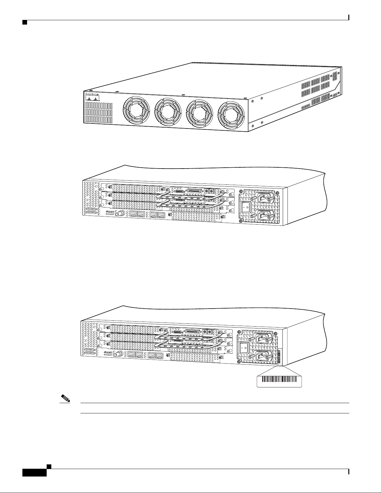
Figure 1-1 Cisco AS5400XM Universal Gateway Front Panel
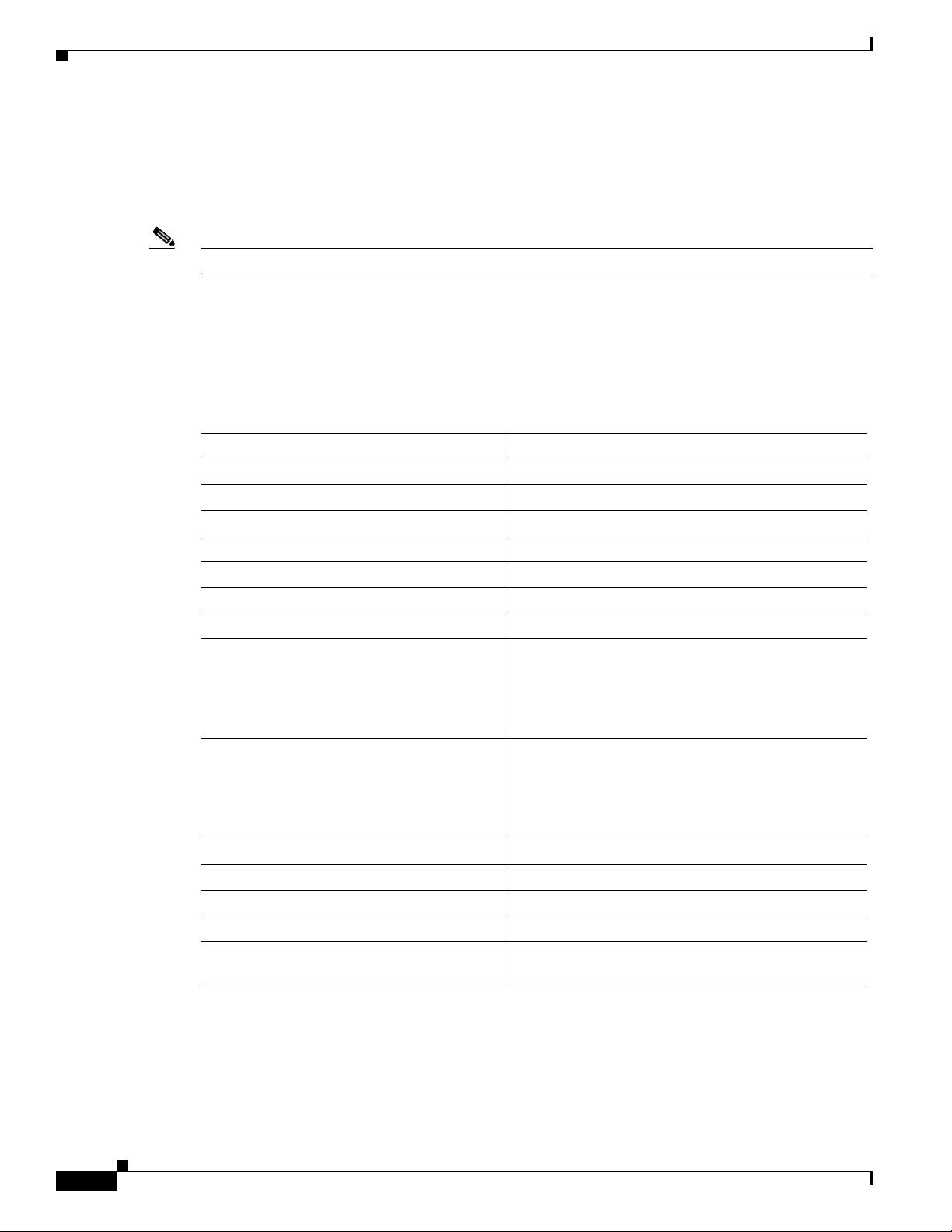
Figure 1-2 Cisco AS5400XM Universal Gateway Rear Panel
Cisco AS5400XM
Chapter 1 Overview
SE
R
IE
S
122113
Product Serial Number Location
The serial number label for the Cisco AS5400XM universal gateway is located on the rear of the chassis,
on the right side. (See
Figure 1-3 Serial Number Location
Figure 1-3.)
29024
135341, 781-00410-01
SN: XXXNNNNXXXX
SN: XXXNNNNXXXX
1-2
Note The serial number for the Cisco AS5400XM universal gateway is 11 characters long.
Cisco AS5400XM Universal Gateway Chassis Installation Guide
OL-6418-02
Page 21

Chapter 1 Overview
Cisco Product Identification Tool
The Cisco Product Identification (CPI) tool provides detailed illustrations and descriptions showing
where to locate serial number labels on Cisco products. It includes the following features:
• A search option that allows browsing for models using a tree-structured product hierarchy
• A search field on the final results page making it easier to look up multiple products
• End-of-sale products are clearly identified in results lists
The tool streamlines the process of locating serial number labels and identifying products. Serial number
information expedites the entitlement process and is important for access to support services.
The Cisco Product Identification tool can be accessed at the following URL:
http://tools.cisco.com/Support/CPI/index.do
Dial Feature Cards
Each dial feature card (DFC) is a 5.1 by 13 inch PCI-based interface board. The following is a brief
description of the trunk types supported:
• North American robbed-bit signaling (RBS) is supported on T1 trunks, including a variety of North
American RBS protocol, framing, and encoding types on these trunks.
Cisco Product Identification Tool
• Channel-associated signaling (CAS) is supported for E1 trunks, with R2 signaling.
• Many countries require an E1 R2 variant. Per-country defaults are provided for supervisory and
• The CT3 DFC provides physical line termination for a channelized T3 ingress trunk line, and it uses
• Universal access (analog modem or digital calls) is supported when an interface is configured for
In any single DFC slot, you can install your choice of:
• One T1 dial feature card
• One E1 dial feature card
• One T3 dial feature card
Note The Cisco AS5400XM universal gateway supports only one type of WAN DFC at a time. For more
information, see the “Mixing WAN DFCs” section on page 4-2.
Power Supply
The power system consists of a fully redundant switching power supply with two AC (or DC) inputs to
the main power modules. Each input and output is 100 percent fully redundant, with dual fans for added
reliability.
inter-register signaling.
an onboard multiplexer to multiplex 28 channelized T1 lines into a single channelized T3 line.
ISDN PRI signaling. PRI signaling is available for both T1 and E1 trunks.
OL-6418-02
Cisco AS5400XM Universal Gateway Chassis Installation Guide
1-3
Page 22
Specifications
The output of each power module is rated at 300 watts (nonredundant mode), and is composed of four
independent output voltages: 3.3V, 5V, 12V and –12V. AC input units have power factor correction and
low harmonic distortion. Units that are in redundant mode run at one-half the power capability. If a
power supply failure occurs, these units are capable of powering the complete system either at the input
side or the DC load side. Power failures are reported through environmental monitoring software.
Note The grounding architecture for the Cisco AS5400XM universal gateway is isolated DC return (DC-I).
Specifications
Table 1-1 provides system specifications for the Cisco AS5400XM universal gateway.
Ta b l e 1-1 Specifications
Description Specification
Dimensions (H x W x D) 3.5 x 17.5 x 18.25 in. (8.89 x 44.45 x 46.36 cm)
Weight 35 lb maximum (15.8 kg)
Processor 250 MHz (Cisco AS5400XM universal gateway)
Operating environment 32 to 104° F (0 to 40° C)
Nonoperating temperature –40 to 185° F (–40 to 85° C)
Operating humidity 5 to 95%, noncondensing
Noise level 70 dB1 @ 3 ft (0.914 m)
Input voltage, AC power supply
Current
Frequency
Power factor
Input AC power
Input voltage, DC power supply
Maximum input current
Typical input current
Efficiency
Input DC power
WAN interface options T1, E1, T3
Serial interfaces (for backhaul WAN support) 2 serial line interfaces
LAN interface options Gigabit Ethernet 10/100/1000BASE-T (RJ-45)
Console and auxiliary ports Asynchronous serial (RJ-45)
Regulatory compliance See the Regulatory Compliance and Safety
1. dB = decibels.
2. VAC = volts alternating current.
3. VDC = volts direct current.
Chapter 1 Overview
100 to 240 VAC2; –10%, +6% tolerance
5 to 2A
50/60 Hz
0.80 to 0.95
200 to 400W (maximum)
–48 to –60 VDC3; –10%, +6% tolerance
9.0A
2.0 to 4.0A
63%
200 to 400W (maximum)
Information publication that came with your gateway.
1-4
Cisco AS5400XM Universal Gateway Chassis Installation Guide
OL-6418-02
Page 23

Preparing to Install
This chapter describes the tasks you must perform before you begin to install the universal gateway and
includes the following sections:
• Safety Recommendations, page 2-1
• Required Tools and Equipment, page 2-3
• Preparing to Connect to a Network, page 2-3
Safety Recommendations
Any device that uses electricity must be handled carefully; follow these guidelines to ensure general
safety:
• Keep the chassis area clear and dust-free during and after installation.
CHA P TER
2
• Put the removed chassis cover in a safe place.
• Keep tools away from walk areas where you and others could fall over them.
• Do not wear loose clothing that could get caught in the chassis. Fasten your tie or scarf and roll up
your sleeves.
• Wear safety glasses if you are working under any conditions that might be hazardous to your eyes.
• Do not perform any action that creates a potential hazard to people or makes the equipment unsafe.
Warning
Ultimate disposal of this product should be handled according to all national laws and regulations.
Statement 1040
Maintaining Safety with Electricity
Warning
Before working on equipment that is connected to power lines, remove jewelry (including rings,
necklaces, and watches). Metal objects will heat up when connected to power and ground and can
cause serious burns or weld the metal object to the terminals.
Follow these guidelines when you work on equipment powered by electricity.
• Locate the emergency power-OFF switch for the room in which you are working. Then, if an
electrical accident occurs, you can act quickly to turn OFF the power.
Statement 43
OL-6418-02
Cisco AS5400XM Universal Gateway Chassis Installation Guide
2-1
Page 24
Safety Recommendations
• Before working on the system, unplug the power cord.
• Disconnect all power before doing the following:
–
Installing or removing a chassis
–
Working near power supplies
Chapter 2 Preparing to Install
Warning
Warning
Warning
When installing or replacing the unit, the ground connection must always be made first and
disconnected last.
• Never assume that power is disconnected from a circuit. Always check.
Read the installation instructions before connecting the system to the power source.
• Look carefully for possible hazards in your work area, such as moist floors, ungrounded power
Statement 1046
Statement 1004
extension cables, frayed power cords, and missing safety grounds.
• If an electrical accident occurs, proceed as follows:
–
Use caution; do not become a victim yourself.
–
Turn OFF power to the system.
–
If possible, send another person to get medical aid. Otherwise, assess the condition of the victim
and then call for help.
–
Determine if the person needs rescue breathing or external cardiac compressions; then take
appropriate action.
This product relies on the building’s installation for short-circuit (overcurrent) protection. Ensure that
a fuse or circuit breaker no larger than 120
phase conductors (all current-carrying conductors).
VAC, 15A U.S. (240 VAC, 10A international) is used on the
Statement 13
Preventing Electrostatic Discharge Damage
Electrostatic discharge (ESD) can damage equipment and impair electrical circuitry. ESD damage occurs
when electronic components are improperly handled and can result in complete or intermittent failures.
Always follow ESD-prevention procedures when you remove and replace components. Ensure that the
chassis is electrically connected to earth ground. Wear an ESD-preventive wrist strap, ensuring that it
makes good skin contact. Connect the grounding clip to an unpainted surface of the chassis frame to
safely ground unwanted ESD voltages. To guard against ESD damage and shocks, the wrist strap and
cord must operate properly. If no wrist strap is available, ground yourself by touching the metal part of
the chassis.
Caution For safety, periodically check the resistance value of the antistatic strap, which should be between 1 and
10 megohm (Mohm).
Cisco AS5400XM Universal Gateway Chassis Installation Guide
2-2
OL-6418-02
Page 25
Chapter 2 Preparing to Install
Required Tools and Equipment
The following items are included with the universal gateway:
• 19- and 24-inch rack-mount kits
• Rubber feet for desktop installation
• RJ-45-to-DB-9 female DTE adapter (labeled TERMINAL)
• RJ-45-to-DB-25 female DTE adapter (labeled TERMINAL)
• RJ-45-to-DB-25 male DCE adapter (labeled MODEM)
• RJ-45-to-RJ-45 rollover console cable
• ESD-preventive wrist strap
• Nylon cable tie
• Cable tie holder
• Grounding lug
You might need the following equipment, which is not included:
Required Tools and Equipment
• Straight-through RJ-45-to-RJ-45 cable for an Ethernet connection
Caution To comply with the intra-building lightning surge requirements of GR-1089-CORE, Issue III, October
2002, you must use a shielded cable when connecting to either of the Cisco
gateway Ethernet ports. The cable must consist of shielded cable terminated by shielded connectors on
both ends, with the cable shield material tied to both connectors.
• Ethernet hub or PC with a network interface card for Ethernet LAN connections
• One breakout cable consisting of a 36-pin connector connected to eight RJ-45 adapters for CT1/CE1
connections
• 75-ohm coaxial cable for a CT3 connection
• PC running terminal emulation software for local administrative access
• Modem for remote administrative access
Preparing to Connect to a Network
When you set up the chassis, consider distance limitations and potential electromagnetic interference
(EMI) as defined by the Electronic Industries Association
AS5400XM universal
(EIA).
OL-6418-02
Warning
Hazardous network voltages are present in WAN ports regardless of whether power to the router is
OFF or ON. To avoid electric shock, use caution when working near WAN ports. When detaching
cables, detach the end away from the router first.
Cisco AS5400XM Universal Gateway Chassis Installation Guide
Statement 77
2-3
Page 26
Preparing to Connect to a Network
Chapter 2 Preparing to Install
Warning
The ISDN connection is regarded as a source of voltage that should be inaccessible to user contact.
Do not attempt to tamper with or open any public telephone operator (PTO)-provided equipment or
connection hardware. Any hardwired connection (other than by a nonremovable,
connect-one-time-only plug) must be made only by PTO staff or suitably trained engineers.
Statement 23
Network Specifications
Table 2-1 lists the network specifications to consider before connecting a T1 DFC to a network.
Ta b l e 2-1 T1 Network Specifications
Description Specification
Line rate 1.544 Mbps
Data rate (per port) number x 56 or number x 64 kbps, where number = 1 to 24
Standards AT&T Pub. 62411, 54016, and 43081, and ANSI T1.403
Input impedance 100 ohms per port
Table 2-2 lists the network specifications to consider before connecting an E1 DFC to a network.
Ta b l e 2-2 E1 Network Specifications
Description Specification
Line rate 2.048 Mbps
Data rate (per port) number x 56 or number x 64 kbps, where number = 1 to 31.
Input impedance 75 or 120-ohms per port
Note The factory default setting for the E1 ports is 120 ohms. Use a
software command to change the impedance.
Table 2-3 lists the network specifications to consider before connecting a T3 DFC to a network.
Ta b l e 2-3 T3 Network Specifications
Description Specification
Line rate 44.736 Mbps
Data rates 672 DS0 channels at 64 kbps
Note For information on installing and removing dial feature cards, see the Cisco AS5350XM and
Cisco AS5400XM Universal Gateways Card Installation Guide.
2-4
Cisco AS5400XM Universal Gateway Chassis Installation Guide
OL-6418-02
Page 27

Chapter 2 Preparing to Install
Ethernet Connections
Two Gigabit Ethernet (GE) ports are RJ-45 ports located on the rear panel of the chassis: GE0 and GE1
(selectable). To configure the Ethernet ports, see the Cisco
Gateways Software Configuration Guide. Both ports use unshielded twisted-pair (UTP) cable and
require Category 5 cable. The maximum segment distance is 328 feet (100 meters). UTP cables look like
the cables used for ordinary telephones; however, UTP cables meet certain electrical standards that
telephone cables do not. Cables are not included.
Caution To comply with the intra-building lightning surge requirements of GR-1089-CORE, Issue III, October
2002, you must use a shielded cable when connecting to either of the Cisco
gateway Ethernet ports. The cable must consist of shielded cable terminated by shielded connectors on
both ends, with the cable shield material tied to both connectors.
Console and Auxiliary Ports
The chassis includes an asynchronous serial console port and an auxiliary port. The console and
auxiliary ports provide access either locally (with a console terminal) or remotely (with a modem). This
section discusses important cabling information to consider before connecting a console terminal (an
ASCII terminal or PC running terminal emulation software) to the console port or modem to the
auxiliary port.
Preparing to Connect to a Network
AS5350XM and Cisco AS5400XM Universal
AS5400XM universal
Console Port
Auxiliary Port
The chassis includes an EIA/TIA-232 asynchronous serial console port (RJ-45). Depending on the cable
and the adapter used, this port appears as a data terminal equipment (DTE) or data communications
equipment (DCE) device at the end of the cable. Your chassis arrives with cables and adapters to connect
a console terminal (an ASCII terminal or PC running terminal emulation software) to the console port.
To connect an ASCII terminal to the console port, use the RJ-45 rollover cable with the female
RJ-45-to-DB-25 adapter (labeled TERMINAL).
To connect a PC running terminal emulation software to the console port, use the RJ-45 rollover cable
with the female RJ-45-to-DB-9 adapter (labeled TERMINAL). The default parameters for the console
port are 9600 baud, 8
flow control.
For detailed information about installing a console terminal, see Chapter 3, “Installing the
Cisco AS5400XM Universal Gateway.” See Appendix C, “Cabling Specifications,” for cable and port
pinouts.
The chassis includes an EIA/TIA-232 asynchronous serial auxiliary port (RJ-45) that supports flow
control. Depending on the cable and the adapter used, this port will appear as a DTE or DCE device at
the end of the cable. Your chassis arrives with a cable and an adapter to connect a modem to the auxiliary
port. To connect a modem to the auxiliary port, use the RJ-45 rollover cable with the male
RJ-45-to-DB-25 adapter (labeled MODEM).
For detailed information about connecting devices to the auxiliary port, see Chapter 3, “Installing the
Cisco AS5400XM Universal Gateway.” See Appendix C, “Cabling Specifications,” for cable and port
pinouts.
data bits, no parity, and 2 stop bits. The console port does not support hardware
OL-6418-02
Cisco AS5400XM Universal Gateway Chassis Installation Guide
2-5
Page 28

Preparing to Connect to a Network
2T Serial Ports
Chapter 2 Preparing to Install
Two high-speed 12-in-1 serial ports on the rear panel of the chassis provide backhaul WAN and IP
support.
The following types of serial interface standards (in DTE or DCE devices) are supported:
• EIA/TIA-232
• EIA/TIA-449
• EIA/TIA-530
• EIA/TIA-530A
• EIA/TIA-X.21
• CCITT V.35
Each port supports up to 8 Mbps.
For detailed information about connecting devices to the serial ports, see Chapter 3, “Installing the
Cisco AS5400XM Universal Gateway.” See Appendix C, “Cabling Specifications,” for cable and port
pinouts.
Alarm Port
The three pins on the alarm port are connected to the output of a relay. This relay is controlled by system
software. With the alarm ports connected and configured, Cisco
detect the failure events that are configured and turns on the alarm when it detects any failure event.
For detailed information about connecting devices to the alarm port, see Chapter 3, “Installing the
Cisco AS5400XM Universal Gateway.” See Appendix C, “Cabling Specifications,” for cable and port
pinouts.
BITS Port
The BITS port is a coaxial interface that provides external synchronized clocking through a timing signal
generator (TSG).
For detailed information about connecting devices to the BITS port, see Chapter 3, “Installing the
Cisco AS5400XM Universal Gateway.” See Appendix C, “Cabling Specifications,” for cable and port
pinouts.
Power Supply Considerations
Check the power at your site to ensure that you are receiving “clean” power (free of spikes and noise).
Install a power conditioner if necessary.
IOS software polls every one second to
2-6
Warning
Cisco AS5400XM Universal Gateway Chassis Installation Guide
The device is designed to work with TN power systems.
Statement 19
OL-6418-02
Page 29
Chapter 2 Preparing to Install
Preparing to Connect to a Network
Warning
This product relies on the building’s installation for short-circuit (overcurrent) protection. Ensure that
a fuse or circuit breaker no larger than 120
phase conductors (all current-carrying conductors).
VAC, 15A U.S. (240 VAC, 10A international) is used on the
Statement 13
The universal gateway AC power supply includes the following features:
• Full range operation—100 to 240 VAC.
• All units include a 6-foot (1.8-m) electrical power cord. (A label near the power cord indicates the
correct voltage, frequency, and current draw for the unit.)
For detailed information about connecting power, see Chapter 3, “Installing the Cisco AS5400XM
Universal Gateway.” For information on replacing the power supply, see Appendix B, “Replacing the
Power Supply.”
Caution In a DC power supply installation, do not connect the 48 VDC Return to chassis ground at the
Cisco
AS5400XM universal gateway. A single-point ground is recommended at the power distribution
rack.
OL-6418-02
Cisco AS5400XM Universal Gateway Chassis Installation Guide
2-7
Page 30

Preparing to Connect to a Network
Chapter 2 Preparing to Install
2-8
Cisco AS5400XM Universal Gateway Chassis Installation Guide
OL-6418-02
Page 31

CHA P TER
3
Installing the Cisco AS5400XM Universal Gateway
This chapter guides you through the installation of the Cisco AS5400XM universal gateway and includes
the following sections:
• Setting Up the Chassis, page 3-1
• Connecting to the Network, page 3-5
• Connecting the Console Terminal and Modem, page 3-9
• Connecting to the BITS Port, page 3-10
• Connecting to the Alarm Port, page 3-11
• Supplying Power, page 3-12
• Where to Go Next, page 3-15
Warning
Warning
Warning
Only trained and qualified personnel should be allowed to install or replace this equipment.
Statement 49
This equipment is intended to be grounded. Ensure that the host is connected to earth ground during
normal use.
Incorrect connection of this or connected equipment to a general purpose outlet could result in a
hazardous situation.
Statement 39
Setting Up the Chassis
You can set the chassis on a desktop or install it in a rack. Use the procedure in this section that best
meets the needs of your network:
• Setting the Chassis on a Desktop
• Rack-Mounting the Chassis
Statement 87
OL-6418-02
Cisco AS5400XM Universal Gateway Chassis Installation Guide
3-1
Page 32

Setting Up the Chassis
Chapter 3 Installing the Cisco AS5400XM Universal Gateway
Warning
Warning
When installing or replacing the unit, the ground connection must always be made first and
disconnected last.
Statement 1046
This unit is intended for installation in restricted access areas. A restricted access area can be
accessed only through the use of a special tool, lock and key, or other means of security.
Statement 1017
Setting the Chassis on a Desktop
The location of the chassis is extremely important for proper operation. Equipment placed too close
together, inadequate ventilation, and inaccessible panels can cause malfunctions and shutdowns, and can
make maintenance difficult. The following information will help you to plan the location of the chassis:
• Plan for access to both front and rear panels of the chassis.
• Ensure that the room where the chassis operates has adequate ventilation. Remember that electrical
equipment generates heat. Ambient air temperature may not cool equipment to acceptable operating
temperatures without adequate ventilation.
Attach the rubber feet as shown in Figure 3-1. Rubber feet are included in the accessory kit that shipped
with your Cisco AS5400XM universal gateway.
Figure 3-1 Attaching the Rubber Feet
3-2
37208
Universal gateway
chassis bottom
Cisco AS5400XM Universal Gateway Chassis Installation Guide
OL-6418-02
Page 33

Chapter 3 Installing the Cisco AS5400XM Universal Gateway
k
Rack-Mounting the Chassis
This section describes how to rack-mount the chassis. The Cisco AS5400XM universal gateway arrives
with 19-inch (48.26-cm) rack-mount brackets and larger brackets for use with a 23- (58.42-cm) or
24-inch (60.96-cm) rack. (See
The following information will help you plan your equipment rack configuration:
• Enclosed racks must have adequate ventilation. Ensure that the rack is not congested, because each
unit generates heat. An enclosed rack should have louvered sides and a fan to provide cooling air.
Heat generated by equipment near the bottom of the rack can be drawn upward into the intake ports
of the equipment above.
• When mounting a chassis in an open rack, ensure that the rack frame does not block the intake or
exhaust ports. If the chassis is installed on slides, check the position of the chassis when it is seated
in the rack.
• Baffles can isolate exhaust air from intake air, which also helps to draw cooling air through the
chassis. The best placement of the baffles depends on the airflow patterns in the rack, which can be
found by experimenting with different configurations.
• When equipment installed in a rack (particularly in an enclosed rack) fails, try operating the
equipment by itself, if possible. Power down other equipment in the rack (and in adjacent racks) to
allow the unit under test a maximum of cooling air and clean power.
• Install the chassis and external devices to which it will connect in a contiguous stack.
Setting Up the Chassis
Figure 3-2.)
Warning
Before working on a chassis or working near power supplies, unplug the power cord on AC units;
disconnect the power at the circuit breaker on DC units.
Required Tools and Equipment
You need the following tools and equipment to rack-mount the chassis:
• Number 2 Phillips screwdriver (not included)
• Screws for attaching the chassis to the rack (not included)
• Standard rack-mount brackets (included)
Figure 3-2 Standard Rack-Mount Brackets
Bracket for 19-inch rack
Statement 12
H6028
Bracket for 23- or 24-inch rac
OL-6418-02
Cisco AS5400XM Universal Gateway Chassis Installation Guide
3-3
Page 34

Setting Up the Chassis
Installing in a Rack
To install the chassis, follow these steps:
Step 1 Attach the brackets as follows with the standard brackets on the side panels of the Cisco AS5400XM
universal gateway and either the front panel forward or the rear panel forward, as shown in
and Figure 3-4.
Figure 3-3 Standard Bracket Installation—Front Panel Forward
Chapter 3 Installing the Cisco AS5400XM Universal Gateway
Figure 3-3
H10643
Figure 3-4 Standard Bracket Installation—Rear Panel Forward
30860
Note: The second bracket attaches to the other side of the chassis.
Caution Do not use the handles on the dial feature cards to assist in lifting the chassis.
Step 2 After the brackets are secured to the chassis, and using the screws that you provide, attach the chassis to
the rack as shown in
Figure 3-5.
3-4
Cisco AS5400XM Universal Gateway Chassis Installation Guide
OL-6418-02
Page 35

Chapter 3 Installing the Cisco AS5400XM Universal Gateway
Figure 3-5 Attaching the Chassis to the 19-Inch Rack—Rear Panel Forward
Note: The second bracket attaches to the rack at the other side
of the chassis. The brackets can also be installed with the
front panel forward.
Connecting to the Network
29034
Connecting to the Network
This section describes how to connect the Cisco AS5400XM universal gateway to your network. The
cables required to connect to a network are not provided. For ordering information, contact customer
service (see the
Specifications,” for cable and port pinouts.
Warning
Warning
Caution If the Cisco AS5400XM universal gateway is configured with fewer than seven DFCs, make sure that a
To avoid electric shock, do not connect safety extra-low voltage (SELV) circuits to telephone-network
voltage (TNV) circuits. LAN ports contain SELV circuits, and WAN ports contain TNV circuits. Some
LAN and WAN ports both use RJ-45 connectors. Use caution when connecting cables.
Do not work on the system or connect or disconnect cables during periods of lightning activity.
Statement 1001
blank slot cover is installed over each open slot to ensure proper airflow.
Note The Cisco AS5400XM universal gateway arrives with all carrier cards and DFCs already installed,
unless you order a card separately as a spare. See the Cisco
Gateways Card Installation Guide for card installation instructions.
“Obtaining Technical Assistance” section on page xvi) or see Appendix C, “Cabling
Statement 1021
AS5350XM and Cisco AS5400XM Universal
OL-6418-02
Cisco AS5400XM Universal Gateway Chassis Installation Guide
3-5
Page 36

Connecting to the Network
Connecting to an Ethernet Network
You can connect the Cisco AS5400XM universal gateway to an Ethernet network by using a
straight-through RJ-45-to-RJ-45 Ethernet cable to connect the Gigabit Ethernet port to an Ethernet hub.
(See
Figure 3-6.)
Caution To comply with the intra-building lightning surge requirements of GR-1089-CORE, Issue III, October
2002, you must use a shielded cable when connecting to either of the Cisco
gateway Ethernet ports. The cable must consist of shielded cable terminated by shielded connectors on
both ends, with the cable shield material tied to both connectors.
Figure 3-6 Connecting to an Ethernet Hub (10/100BASE-T Shown)
Chapter 3 Installing the Cisco AS5400XM Universal Gateway
AS5400XM universal
1 GE1 10/100/1000BASE-T port
2 Ethernet hub
3 Straight-through Ethernet cable
Connecting to a WAN
Warning
The telecommunications lines must be disconnected 1) before unplugging the main power connector
and/or 2) while the housing is open.
1
8
7
1
2
122115
3
Statement 89
3-6
Warning
Hazardous network voltages are present in WAN ports regardless of whether power to the router is
OFF or ON. To avoid electric shock, use caution when working near WAN ports. When detaching
cables, detach the end away from the router first.
Warning
This equipment is to be installed and maintained by service personnel only as defined by AS/NZS 3260
Clause 1.2.14.3 Service Personnel.
Cisco AS5400XM Universal Gateway Chassis Installation Guide
Statement 77
Statement 88
OL-6418-02
Page 37

Chapter 3 Installing the Cisco AS5400XM Universal Gateway
30848
Connecting to the Network
Warning
To reduce the risk of fire, use only No. 26 AWG or larger telecommunication line cord.
Statement 1023
You can connect the Cisco AS5400XM universal gateway to a WAN in the following ways:
• Use a breakout cable and straight-through RJ-45-to-RJ-45 cable for CT1 connections. (See
Figure 3-7.)
Figure 3-7 Connecting to an RJ-45C (T1) Jack
0
1
2
P
T1/E1 8 PRI
P
P
P
connector
3
4
5
6
P
7
P
P
P
Straight-through
RJ-45-to-RJ-45 cable
RJ-45 jack
Warning
• Use an E1 cable to connect each E1/PRI port to an E1 channel service unit (CSU) or data service
unit (DSU). (See
Figure 3-8.)
Note If you choose a port with 75-ohm input impedance, use an RJ-45-to-75-ohm coaxial cable
adapter and plug it into that port. Use software commands to choose a particular port and the line
termination on that port. For information on software commands, see the Cisco
AS5350XM and
Cisco AS5400XM Universal Gateways Software Configuration Guide.
The E1 interface card may only be installed in an ACA-permitted customer equipment or a Data
Terminal Equipment (DTE) that is exempted from ACA’s permit requirements. The customer equipment
must only be housed in a cabinet that has screw-down lids to stop user access to overvoltages on the
customer equipment. The customer equipment has circuitry that may have telecommunications
network voltages on them.
Statement 90
OL-6418-02
Cisco AS5400XM Universal Gateway Chassis Installation Guide
3-7
Page 38

Connecting to the Network
Figure 3-8 Connecting to an RJ-45 Jack
T1/E1 8 PRI
0
1
P
P
connector
Chapter 3 Installing the Cisco AS5400XM Universal Gateway
30847
2
3
4
P
5
P
6
P
7
P
P
P
E1 cable
RJ-45 jack
• Use a serial transition cable to connect one of the two synchronous serial ports to a modem or a
CSU/DSU. (See
Figure 3-9.)
Figure 3-9 Connecting to a CSU/DSU
Synchronous serial
port (DB-26)
Serial
transition
cable
EIA/TIA-232, EIA/TIA-449, EIA/TIA-530A,
EIA/TIA-530, V.35, or X.21 connector
CSU/DSU or
other DCE or DTE
Internet
30846
3-8
Note For cable and port pinouts for specific dial feature cards, see Appendix C, “Cabling
Specifications,” in the Cisco AS5350XM and Cisco AS5400XM Universal Gateways Card
Installation Guide.
Cisco AS5400XM Universal Gateway Chassis Installation Guide
OL-6418-02
Page 39

Chapter 3 Installing the Cisco AS5400XM Universal Gateway
Connecting the Console Terminal and Modem
Connecting the Console Terminal and Modem
Use the console terminal for local administrative access to the Cisco AS5400XM universal gateway. You
can only connect a terminal to the console port. You can use the auxiliary port to connect a terminal or
a modem for remote access.
Connecting to the Console Port
To connect a terminal (an ASCII terminal or a PC running terminal emulation software) to the console
port, follow these steps:
Step 1 Connect the terminal using an RJ-45 rollover cable and an RJ-45-to-DB-25 or RJ-45-to-DB-9 adapter.
The adapters provided are labeled TERMINAL. Other types of adapters are not included. (See
Figure 3-10.)
Figure 3-10 Connecting the Console Terminal
Console port
(RJ-45)
RJ-45-to-RJ-45
rollover cable
RJ-45
Note For additional information on rollover cable pinouts, see Appendix C, “Cabling Specifications.”
PC (laptop)
30845
OL-6418-02
Cisco AS5400XM Universal Gateway Chassis Installation Guide
3-9
Page 40

Connecting to the BITS Port
30850
Step 2 Configure your terminal or PC terminal emulation software for 9600 baud, 8 data bits, no parity, and
2
stop bits. To configure the console port, see the Cisco AS5350XM and Cisco AS5400XM Universal
Gateways Software Configuration Guide.
Connecting a Modem to the Auxiliary Port
To connect a modem to the auxiliary port, follow these steps:
Step 1 Connect a modem to the auxiliary port using an RJ-45 rollover cable with an RJ-45-to-DB-25 adapter.
The adapter provided is labeled MODEM. (See
Figure 3-11 Connecting a Modem to the Auxiliary Port
Chapter 3 Installing the Cisco AS5400XM Universal Gateway
Figure 3-11.)
0
1
2
P
T1/E1 8 PRI
connector
3
P
4
P
5
P
6
P
7
P
P
P
RJ-45-to-RJ-45
rollover cable
Step 2 Make sure that your modem and the auxiliary port on the Cisco AS5400XM universal gateway are
configured for the same transmission speed (38400 baud is typical) and hardware flow control with Data
Carrier Detect (DCD) and Data Terminal Ready (DTR) operations.
Connecting to the BITS Port
Use a coaxial cable to connect a timing signal generator (TSG) to the BITS port. The BITS port is used
for external clocking. (See
Figure 3-12.)
Auxiliary port
(RJ-45)
Modem
RJ-45-to-DB-25 adapter
(labeled MODEM)
3-10
Cisco AS5400XM Universal Gateway Chassis Installation Guide
OL-6418-02
Page 41

Chapter 3 Installing the Cisco AS5400XM Universal Gateway
Figure 3-12 Connecting to the BITS Port
Connecting to the Alarm Port
Satellite global
positioning system
Timing signal
generator
Coaxial cable
Connecting to the Alarm Port
Connect to the alarm port as follows:
Step 1 Insert the three-pin alarm port connector into the alarm port terminal block. (See Figure 3-13.)
Figure 3-13 Connecting to the Alarm Port
52503
Universal gateway
OL-6418-02
Alarm port
connector
Cable ties
Note Connect the alarm port only to a safety extra-low voltage (SELV) source using 22 AWG, or
#1#2#3
35145
thicker, copper wire. SELV ratings are maximum 30 volts AC (RMS), maximum 60 volts DC,
and maximum 50 VA power. The alarm port is rated for 2.0-amp maximum current.
Cisco AS5400XM Universal Gateway Chassis Installation Guide
3-11
Page 42

Supplying Power
Step 2 Strip a minimum 1/4 in. (0.625 cm) off the wire insulation to connect the stranded wires to the alarm
connector. The maximum insulation strip length is 0.31 in. (0.78 cm).
Step 3 Secure the wires to the alarm connector with screws.
Caution The maximum tightening torque on the screws is 7 in.-lb (0.79 N-m).
Step 4 Connect the wires to strain relief clamps that are inserted into the holes in the ventilation grid.
Note See Appendix C, “Cabling Specifications,” for alarm port cable assembly and port pinouts.
Supplying Power
The power system consists of a fully redundant switching power supply with two AC (or DC) inputs to
the main power modules. See the
power system.
Check the power at your site to ensure that you are receiving “clean” power (free of spikes and noise).
Install a power conditioner if necessary.
Chapter 3 Installing the Cisco AS5400XM Universal Gateway
“Power Supply” section on page 1-3 for more information about the
The Cisco AS5400XM universal gateway AC power supply includes the following features:
• The full range of operation is 100 to 240 VAC.
• All units include two 6-foot (1.8-meter) electrical power cords. (A label near the power inlets
indicates the correct voltage, frequency, current draw, and power dissipation for the unit.)
Caution In a DC power supply installation, do not connect the 48 VDC Return to chassis ground at the
Cisco
AS5400XM universal gateway. A single-point ground is recommended at the power distribution
rack.
Note The grounding architecture for the Cisco AS5400XM universal gateway is isolated DC return (DC-I).
Warning
Warning
Do not touch the power supply when the power cord is connected. For systems with a power switch,
line voltages are present within the power supply even when the power switch is off and the power
cord is connected. For systems without a power switch, line voltages are present within the power
supply when the power cord is connected.
This product relies on the building’s installation for short-circuit (overcurrent) protection. Ensure that
a fuse or circuit breaker no larger than 120 VAC, 15A U.S. (240 VAC, 10A international) is used on the
phase conductors (all current-carrying conductors).
Statement 4
Statement 13
3-12
Cisco AS5400XM Universal Gateway Chassis Installation Guide
OL-6418-02
Page 43

Chapter 3 Installing the Cisco AS5400XM Universal Gateway
Supplying Power
Warning
The device is designed to work with TN power systems.
Connecting the AC Power Cord
To connect the power cord, follow these steps:
Step 1 Connect one end of each power cord to the power connectors on the rear panel. (See Figure 3-14.)
Figure 3-14 Connecting the AC Power Cord
Statement 19
Power switch
30851
Step 2 Latch the clips provided on the power supply of the chassis to each power cord.
Step 3 Connect the other end of the power cords to the power outlets.
Warning
Step 4 Power up the Cisco AS5400XM universal gateway.
The plug-socket combination must be accessible at all times, because it serves as the main
disconnecting device.
The internal power supply fan should power up.
Wiring the DC Power Supply
If you ordered the Cisco AS5400XM universal gateway with a DC power supply, follow the procedure
in this section to wire the terminal block.
Note The grounding architecture for the Cisco AS5400XM universal gateway is isolated DC return (DC-I).
Statement 1019
OL-6418-02
Cisco AS5400XM Universal Gateway Chassis Installation Guide
3-13
Page 44

Supplying Power
Chapter 3 Installing the Cisco AS5400XM Universal Gateway
Warning
A readily accessible two-poled disconnect device must be incorporated in the fixed wiring.
Statement 1022
Warning
Before performing any of the following procedures, ensure that power is removed from the DC circuit.
Statement 1003
Warning
Before connecting or disconnecting ground or power wires to the chassis, ensure that power is
removed from the DC circuit. To ensure that all power is OFF, locate the circuit breaker on the panel
board that services the DC circuit, switch the circuit breaker to the OFF position, and tape the switch
handle of the circuit breaker in the OFF position.
Statement 140
Note This product is intended for installation in restricted access areas and is approved for connection using
12 or 14 AWG copper conductors only. The installation must comply with all applicable codes.
See Figure 3-15 and follow these steps to wire the terminal blocks:
Step 1 Note the orientation of the DC power supply. The power supply cord should have three wires: 48 VDC
Return, –48 VDC, and a safety ground (green wire).
Warning
The illustration shows the DC power supply terminal block. Wire the DC power supply using the
appropriate lugs at the wiring end, or with no lugs, as illustrated. The proper wiring sequence is
ground to ground, positive to positive, and negative to negative. Note that the ground wire should
always be connected first and disconnected last.
Statement 197
Figure 3-15 DC Power Supply Connections
Mounting screwMounting screw
Terminal
block
Terminal
block
31628
LEDs
On/off
switch
LEDs
Mounting
screw
Strain-relief
clamps
IN OK
DC OK
OTF
IN OK
DC OK
OTF
Strain-relief
clamps
3-14
Cisco AS5400XM Universal Gateway Chassis Installation Guide
OL-6418-02
Page 45

Chapter 3 Installing the Cisco AS5400XM Universal Gateway
Caution In a DC power supply installation do not connect the 48 VDC Return to chassis ground at the
Cisco
AS5400XM universal gateway. A single-point ground is recommended at the power distribution
rack.
Step 2 Strip off 1/4 in. (0.625 cm) of insulation on the safety ground, 48 VDC Return, and –48 VDC input
wires.
Step 3 Insert the safety grounds (green wire) into the terminal block ground connectors and tighten the locking
screws. Ensure that no bare wire is exposed.
Note For central office installations, we recommend using a copper 6 AWG green ground wire with one end
connected to reliable earth. The other end of the wire should be crimped onto the double-hole lug
provided in the installation pack. The lug should be secured to the mating holes on either side of the
chassis with the two screws included in the accessory pack.
Caution Do not overtorque the terminal block contact screws. The recommended torque is 5.0 in.-lb (0.56 N-m).
Where to Go Next
Step 4 Insert both 48 VDC Return wires into the terminal block positive connectors (+) and tighten the locking
screws. Ensure that no bare wire is exposed.
Step 5 Insert both –48 VDC wires into the terminal block negative connectors (–) and tighten the locking
screws. Ensure that no bare wire is exposed.
Step 6 Secure the power supply cords to the cable strain-relief clamps on the DC power supply with cable ties.
(See
Figure 3-15.)
Warning
Step 7 Power up the Cisco AS5400XM universal gateway.
After wiring the DC power supply, remove the tape from the circuit breaker switch handle and
reinstate power by moving the handle of the circuit breaker to the ON position.
The internal power supply fan should power up.
Where to Go Next
When you power up the Cisco AS5400XM universal gateway for the first time, messages begin to appear
on your console screen. See the Cisco
Configuration Guide for configuration instructions. The remaining chapters and appendixes of this guide
include reference material for replacing spare parts, troubleshooting, and creating your own cables:
• Chapter 4, “Troubleshooting”
Statement 8
AS5350XM and Cisco AS5400XM Universal Gateways Software
OL-6418-02
• Appendix A, “Replacing Memory Components”
• Appendix B, “Replacing the Power Supply”
• Appendix C, “Cabling Specifications”
Cisco AS5400XM Universal Gateway Chassis Installation Guide
3-15
Page 46

Where to Go Next
Chapter 3 Installing the Cisco AS5400XM Universal Gateway
3-16
Cisco AS5400XM Universal Gateway Chassis Installation Guide
OL-6418-02
Page 47

LEDs
CHA P TER
4
Troubleshooting
This chapter describes how to troubleshoot the Cisco AS5400XM universal gateway by referring to the
LEDs on the chassis and DFCs, and using the bantam jack connectors. The chapter contains the
following sections:
• LEDs, page 4-1
• Mixing WAN DFCs, page 4-2
• Environment Monitoring, page 4-3
• Using the Bantam Jacks for Test Port Functionality, page 4-6
• Troubleshooting Network Interfaces, page 4-7
• Getting Help, page 4-7
The LEDs indicate the current operating condition of the universal gateway. You can observe the LEDs,
note any fault condition that the product is encountering, and then contact your system administrator or
a customer service representative (see the
necessary. Figure 4-1 shows the location of the LEDs. Tab l e 4-1 describes the LEDs.
Figure 4-1 Universal Gateway Rear Panel LEDs
T1
BITS
T0
ACTIVITY (ACT)
“Obtaining Technical Assistance” section on page xvi), if
LNK
ACTIVITY (ACT)
BOARD OK
LED
LNK
31629
OL-6418-02
Cisco AS5400XM Universal Gateway Chassis Installation Guide
4-1
Page 48

Chapter 4 Troubleshooting
Mixing WAN DFCs
Ta b l e 4-1 Chassis LEDs
LED State Description
Alarm On An alarm error has been detected.
Off Remains off when operation is normal.
Gigabit Ethernet Activity (ACT) Flickering The Gigabit Ethernet LAN connection is transmitting and receiving data
normally.
Gigabit Ethernet Link (LNK) On The Gigabit Ethernet cable is connected properly.
Off The Ethernet LAN connection is not transmitting or receiving data.
Check the Ethernet cable connections.
OK/MAINT On The system board is operating normally.
Off Power is off or the system has not booted.
Blinking A memory failure occurred.
Serial Ports Activity (ACT) Flickering The serial port connection is transmitting and receiving data normally.
Serial Ports Link (LNK) On The serial port cable is connected properly.
Off The serial port cable is not connected properly.
BITS Port On Indicates a valid signal on the BITS port.
Off Remains off when operation is normal.
Remote Alarm (RA) On Indicates a T1 alarm condition encountered by software.
Off Remains off when operation is normal.
Local Alarm (LA) On Indicates a T1 alarm condition encountered by software for a particular
port.
Off Remains off when operation is normal.
Mixing WAN DFCs
The Cisco AS5400XM supports only one type of WAN DFC at a time. The DFCs that can be installed
at one time are:
• Four T1 DFCs
• Four E1 DFCs
• One CT3 DFC and three T1 DFCs
The Cisco AS5400XM software recognizes DFCs in the order of the slots they are in. For example, a
DFC in slot 2 is recognized before a DFC in slot 3. The system recognizes if there is a mix of WAN DFCs
during both power up and OIR:
• During power up, the first WAN DFC recognized by the system is the only type brought up.
• If there are two or more WAN DFCs of the same type and one is hot-swapped with another of a
different type, the new one is not recognized.
In both situations, an error message appears on the console that is similar to the following example:
00:01:12:%CARRIER-2-T1_E1_MIX:Cannot mix T1 and E1 8PRI DFC cards in chassis, do not power
up invalid card in slot 7
Cisco AS5400XM Universal Gateway Chassis Installation Guide
4-2
OL-6418-02
Page 49

Chapter 4 Troubleshooting
To see what types of DFCs are in the chassis, use the show chassis slot command in privileged EXEC
mode:
Router# show chassis slot
Slot 1:
DFC type is AS5400 T1 8 PRI DFC
OIR events:
Number of insertions = 0, Number of removals = 0
DFC State is DFC_S_OPERATIONAL
Slot 2:
Carrier Slot is Empty
Slot 3:
Carrier Slot is Empty
Slot 4:
DFC type is AS5400 NP108 DFC
OIR events:
Number of insertions = 0, Number of removals = 0
DFC State is DFC_S_OPERATIONAL
Environment Monitoring
Slot 5:
DFC type is AS5400 Empty DFC
DFC is not powered
OIR events:
Number of insertions = 0, Number of removals = 0
Slot 6:
Carrier Slot is Empty
Slot 7:
Carrier Slot is Empty
Environment Monitoring
The Cisco AS5400XM contains temperature sensors to detect abnormal temperature conditions during
system operation. The three levels of sensor detection are as follows:
1. When the operating temperature of the system exceeds 113° F (45° C), the system reaches a warning
state. A warning message appears on the console. When the operating temperature of the system
drops below 113° F (45° C), another message is displayed on the console indicating a recovery. At
this level of sensor detection, there is no disruption in system operation.
2. When the operating temperature of the system continues to rise above 113° F (45° C) and reaches a
temperature of 140° F (60° C), the system reaches a critical state.
Cisco IOS software busys out the DFCs in the chassis and shuts down the first DFC. If the operating
temperature continues to be critical after 10 minutes, Cisco
This process is repeated at 10-minute intervals until the final DFC is shut down. The console
displays the slot number of the DFC and the type of DFC that was shut down.
IOS software shuts down another DFC.
OL-6418-02
Note DFC slot numbering starts from the system board and works up from left to right. Slot 0 is
reserved for the system board. The DFC slots are numbered sequentially from 1 to 7.
Cisco AS5400XM Universal Gateway Chassis Installation Guide
4-3
Page 50

Environment Monitoring
If the operating temperature cools down to 113° F (45° C), Cisco IOS software powers up the first
DFC, repeating the process for each DFC at 10 minute intervals.
3. When the operating temperature of the system rises above 140° F (65° C), Cisco IOS software shuts
down all DFCs immediately.
Displaying Environment Status
You can use the command line interface (CLI) to check environment monitoring status of the
Cisco
AS5400XM universal gateway. To check environment monitoring status, enter the show
environment command in privileged EXEC mode:
Router# show environment
• The display shown below appears on your console during normal operating conditions. The slot
number corresponds to the DFC in that slot. The outlet and inlet sensors read the temperature of the
air circulating inside the chassis.
Router# show environment
Temperature:
Temperature Reading:
Temperature at inlet is measured as 22C/71F.
Temperature at outlet is measured as 27C/80F.
Temperature State:
Temperature is in normal state.
Fans:
Fans temperature delta is measured as 5C.
All fans are running well.
Power Supply:
Redundant Power System is present.
Chapter 4 Troubleshooting
• The display below appears on your console when the system reaches a warning state:
Router# show environment
Temperature:
Temperature Reading:
Temperature at inlet is measured as 52C/125F.
Temperature at outlet is measured as 64C/147F.
Temperature State:
Temperature is in warning state.
Fans:
Fans temperature delta is measured as 6C.
All fans are running well.
Power Supply:
Redundant Power System is present.
RPS Input Voltage status: normal
RPS Output Voltage status: normal
RPS Fan status: normal
RPS Thermal status: normal
RPS OverVoltage status: normal
Environmental monitor experienced the following events:
Temperature:sensor failed.
Fans:monitor dropped.
Temperature:warning.
Temperature:sensor recovered.
Fans:monitor recovered.
Fans:normal.
• The display below appears on your console when the system reaches a critical state:
Router# show environment
Temperature:
4-4
Cisco AS5400XM Universal Gateway Chassis Installation Guide
OL-6418-02
Page 51

Chapter 4 Troubleshooting
Environment Monitoring
Temperature Reading:
Temperature at inlet is measured as 62C/143F.
Temperature at outlet is measured as 74C/165F.
Temperature State:
Temperature is in critical state.
DFC Busyout/Power-down:
A DFC is powered down. Slot:1, Type:NP108 DFC
A DFC is busyout. Slot:2, Type:T1 8 PRI DFC
A DFC is busyout. Slot:3, Type:NP108 DFC
Fans:
Fans temperature delta is measured as 6C.
All fans are running well.
Power Supply:
Redundant Power System is present.
RPS Input Voltage status: normal
RPS Output Voltage status: normal
RPS Fan status: normal
RPS Thermal status: normal
RPS OverVoltage status: normal
Environmental monitor experienced the following events:
Temperature:sensor failed.
Fans:monitor dropped.
Temperature:warning.
Temperature:sensor recovered.
Fans:monitor recovered.
Fans:normal.
Temperature:critical.
• The display below appears on your console when the system reaches a shutdown state:
Router# show environment
Temperature:
Temperature Reading:
Temperature at inlet is measured as 70C/158F.
Temperature at outlet is measured as 82C/179F.
Temperature State:
Temperature is in shutdown state.
DFC Busyout/Power-down:
A DFC is powered down. Slot:1, Type:NP108 DFC
A DFC is powered down. Slot:2, Type:T1 8 PRI DFC
A DFC is powered down. Slot:3, Type:NP108 DFC
Fans:
Fans temperature delta is measured as 6C.
All fans are running well.
Power Supply:
Redundant Power System is present.
RPS Input Voltage status: normal
RPS Output Voltage status: normal
RPS Fan status: normal
RPS Thermal status: normal
RPS OverVoltage status: normal
Environmental monitor experienced the following events:
Temperature:sensor failed.
Fans:monitor dropped.
Temperature:warning.
Temperature:sensor recovered.
Fans:monitor recovered.
Fans:normal.
Temperature:critical.
Temperature:shutdown.
OL-6418-02
Cisco AS5400XM Universal Gateway Chassis Installation Guide
4-5
Page 52

Using the Bantam Jacks for Test Port Functionality
Using the Bantam Jacks for Test Port Functionality
You can use the bantam jack connectors on the DFCs for test port functionality, as explained in the
following sections.
Monitor Mode for the T1, E1, and T3 DFCs
The Monitor mode is available on the T1, E1, and T3 dial feature cards.
If a T1 controller does not come up, or there are a large number of errors associated with a particular
controller, you might be able to determine whether the problem is in the DFC or in an external T1 line
by using the test port. The test port is a set of bantam jack connectors located on the front panel of the
DFCs.
In monitor mode, you can monitor only the ingress side of the T1 line without disrupting that line.
The bantam jack connectors located on the front panel of the DFCs allow the connection of an external
test device (for example, a FIREBERD test device) to monitor the individual T1 circuit in monitor mode.
Use software commands to select a T1 line. For information on software commands, see the
Cisco
AS5350 and Cisco AS5400XM Universal Gateways Software Configuration Guide for details.
Passive monitoring equipment is used to listen on the TX MON and RX MON jacks during regular
operation to detect T1 errors.
Connecting test equipment to the following bantam jack connectors provides various functions:
Chapter 4 Troubleshooting
• TX MON can monitor signals coming out of the test port without interrupting normal data
transmission.
• RX MON can monitor signals going in to the test port without interrupting normal data transmission.
Drop and Insert Mode for the CT3 DFC
Drop and insert mode is available on the CT3 dial feature card.
The bantam jack connectors located on the front panel of the card allow the connection of an external
test device (for example, a FIREBERD test device) to test any of the 28 individual T1 circuits in drop
and insert mode. In drop and insert mode, the T1 line is dropped out of service.
Note In drop and insert mode, the T1 line is dropped out of service. To prevent accidental use of the
push button in drop and insert mode, use the test trunk drop-insert privileged EXEC command
to disable the drop and insert mode on the specified T3 controller.
The test trunk drop-insert privileged EXEC command is used to enable or disable drop and insert mode
on a T3 controller. When the system initially boots up, the drop and insert mode is disabled on all T3
controllers.
To drop a particular T1 line to the test port, follow these steps:
Step 1 Enable drop and insert mode by entering the test trunk drop-insert on command in privileged EXEC
mode:
Router# test trunk drop-insert on
t1port
4-6
Cisco AS5400XM Universal Gateway Chassis Installation Guide
OL-6418-02
Page 53

Chapter 4 Troubleshooting
Note The t1 port is the particular T1 line that you wish to drop. T1 port numbers range from 1 to 28.
Step 2 Disable drop and insert mode after testing the T1 lines. We recommend that you disable drop and insert
mode to prevent accidental use of the push button on the CT3 card.
To disable drop and insert mode, enter the test trunk drop-insert off command in privileged EXEC
mode:
Router# test trunk drop-insert off
t1 port
Troubleshooting Network Interfaces
For information about isolating problems with the network connections to your universal gateway, see
the Internetwork Troubleshooting Guide publication available on Cisco.com.
Troubleshooting Network Interfaces
Getting Help
For information about technical support, onsite service, and exchange and repair services, see the
“Obtaining Technical Assistance” section on page xvi.
OL-6418-02
Cisco AS5400XM Universal Gateway Chassis Installation Guide
4-7
Page 54

Getting Help
Chapter 4 Troubleshooting
4-8
Cisco AS5400XM Universal Gateway Chassis Installation Guide
OL-6418-02
Page 55

Replacing Memory Components
This appendix contains procedures on how to replace memory chips in the Cisco AS5400XM universal
gateway. The appendix contains the following sections:
• Removing the Chassis Cover, page A-1
• Replacing the Compact Flash, page A-5
• Replacing DIMMs, page A-7
• Replacing the Chassis Cover, page A-9
Removing the Chassis Cover
This section describes how to open the chassis by removing the chassis cover.
APPENDIX
A
Required Tools
You need the following tools:
• Medium Phillips screwdriver
• Small or medium flat-blade screwdriver
Safety Recommendations
Note the following safety recommendations:
Warning
Warning
Before opening the unit, disconnect the telephone-network cables to avoid contact with
telephone-network voltages.
Do not work on the system or connect or disconnect cables during periods of lightning activity.
Statement 1001
Statement 1041
OL-6418-02
Cisco AS5400XM Universal Gateway Chassis Installation Guide
A-1
Page 56

Removing the Chassis Cover
Appendix A Replacing Memory Components
Warning
Before working on a chassis or working near power supplies, unplug the power cord on AC units;
disconnect the power at the circuit breaker on DC units.
NVRAM in the universal gateway uses an internal lithium battery to maintain data. Although this is not
a field-serviceable component, we are required to provide the following safety warning:
Warning
Warning
There is the danger of explosion if the battery is replaced incorrectly. Replace the battery only with
the same or equivalent type recommended by the manufacturer. Dispose of used batteries according
to the manufacturer’s instructions.
Before working on equipment that is connected to power lines, remove jewelry (including rings,
necklaces, and watches). Metal objects will heat up when connected to power and ground and can
cause serious burns or weld the metal object to the terminals.
Chassis Cover Removal
You must open the chassis to gain access to its interior components: boot read-only memory (ROM) and
synchronous dynamic random-access memory dual in-line memory modules (SDRAM DIMMs). When
you replace the compact flashs, you must also remove all feature cards in the chassis.
To remove the chassis cover, follow these steps:
Statement 12
Statement 1015
Statement 43
Step 1 Turn the power switch off and disconnect site power. (Note that the power switch is part of the power
supply.)
Step 2 If using a DC-powered unit, see Figure A-1 and complete Step a through Step d.
Warning
Before connecting or disconnecting ground or power wires to the chassis, ensure that power is
removed from the DC circuit. To ensure that all power is OFF, locate the circuit breaker on the panel
board that services the DC circuit, switch the circuit breaker to the OFF position, and tape the switch
handle of the circuit breaker in the OFF position.
Statement 140
A-2
Cisco AS5400XM Universal Gateway Chassis Installation Guide
OL-6418-02
Page 57

Appendix A Replacing Memory Components
Figure A-1 DC Power Supply Connections
Removing the Chassis Cover
Mounting screwMounting screw
LEDs
On/off
switch
LEDs
Mounting
screw
Strain-relief
clamps
IN OK
DC OK
OTF
IN OK
DC OK
OTF
Strain-relief
clamps
a. Loosen the six locking screws for the negative, return, and ground connections on the DC power
supply terminal blocks.
b. Remove the –48 VDC wires from the terminal block negative connectors (–).
c. Remove the 48 VDC wires from the terminal block positive connectors (+).
d. Remove the safety ground (green wires) from the terminal block ground connectors.
Step 3 Remove all interface cables from the rear panel of the chassis.
Terminal
block
Terminal
block
31628
Step 4 Place the chassis so that the front panel is facing you.
Step 5 Remove the four screws on the chassis cover. (See Figure A-2.)
Caution Do not connect a 48 VDC wire to the chassis. A single-point ground is recommended at the power
distribution rack.
OL-6418-02
Cisco AS5400XM Universal Gateway Chassis Installation Guide
A-3
Page 58

Removing the Chassis Cover
Figure A-2 Removing the Chassis Cover Screws
Appendix A Replacing Memory Components
4
30852
Step 6 Gently pry the cover off with a flat-blade screwdriver. Lift the chassis cover upward, and pull it away
from the tabs on the rear of the chassis. (See
Figure A-3.)
Figure A-3 Removing the Chassis Cover
Chassis cover
Cisco AS5400
SER
IES
29035
Front panel
Chassis bottom
A-4
Cisco AS5400XM Universal Gateway Chassis Installation Guide
OL-6418-02
Page 59

Appendix A Replacing Memory Components
Replacing the Compact Flash
To replace the compact flash, follow these steps:
Step 1 Turn the power switch off and disconnect site power.
For DC-powered units, note the following warnings:
Replacing the Compact Flash
Warning
Warning
Warning
Step 2 Remove all interface cables from the DFCs.
Step 3 Attach an ESD-preventive wrist strap.
Step 4 Remove the chassis cover. (See the instructions in the “Removing the Chassis Cover” section on
Before performing any of the following procedures, ensure that power is removed from the DC circuit.
Statement 1003
Before connecting or disconnecting ground or power wires to the chassis, ensure that power is
removed from the DC circuit. To ensure that all power is OFF, locate the circuit breaker on the panel
board that services the DC circuit, switch the circuit breaker to the OFF position, and tape the switch
handle of the circuit breaker in the OFF position.
Before opening the unit, disconnect the telephone-network cables to avoid contact with
telephone-network voltages.
Statement 1041
Statement 140
page A-1.)
Step 5 Locate the compact flash on the system board. (See Figure A-4.)
OL-6418-02
Cisco AS5400XM Universal Gateway Chassis Installation Guide
A-5
Page 60

Replacing the Compact Flash
Figure A-4 Memory Locations
Appendix A Replacing Memory Components
1
12
11
10
2
122110
A-6
9
8
6 5 4 3
7
1 Backplane connector 2 System board DFC connector
3 AUX 4 CON
5 GE1 6 GE0
7 BITS port 8 Alarm port
9 2T serial interface 10 Compact flash
11 DIMM slot 12 32-bit PCI interface
Cisco AS5400XM Universal Gateway Chassis Installation Guide
OL-6418-02
Page 61

Appendix A Replacing Memory Components
Step 6 Using your fingers, gently extract the old compact flash and set it on a nonconductive surface. Do not
use excessive force, because the socket might break.
Step 7 Insert the new compact flash into the socket. Be careful not to bend or crush any of the bottom pins. If
necessary, use needlenose pliers to straighten out any bent pins.
Step 8 Replace the chassis cover. (See the instructions in the “Replacing the Chassis Cover” section on
page A-9.)
Step 9 Power up the universal gateway. If error messages relating to memory are displayed, remove the new
compact flash and reinstall it, taking care to seat the compact flash firmly in the socket.
Replacing DIMMs
This section describes how to replace a DIMM on the Cisco AS5400XM universal gateway. The
universal gateway has a single DIMM (see
double data rate (DDR1) SDRAM DIMM.
You might need to upgrade the DIMM for the following reasons:
• You have upgraded to a new Cisco IOS feature set or release that requires more memory.
Replacing DIMMs
Figure A-4). The default factory configuration is a 512 MB
• You are using very large routing tables or many protocols (for example, when the universal gateway
is set up as a connection device between large external networks and your internal network).
Required Tools and Equipment
You need the following tools and equipment:
• ESD-preventive wrist strap
• Appropriate DIMM
Replacing the DIMM
To replace the DIMM, follow these steps:
Step 1 Power down the universal gateway and disconnect site power.
For DC-powered units only, note the following warning.
Warning
Before performing any of the following procedures, ensure that power is removed from the DC circuit.
Statement 1003
OL-6418-02
Warning
Before connecting or disconnecting ground or power wires to the chassis, ensure that power is
removed from the DC circuit. To ensure that all power is OFF, locate the circuit breaker on the panel
board that services the DC circuit, switch the circuit breaker to the OFF position, and tape the switch
handle of the circuit breaker in the OFF position.
Cisco AS5400XM Universal Gateway Chassis Installation Guide
Statement 140
A-7
Page 62

Replacing DIMMs
Appendix A Replacing Memory Components
Warning
Step 2 Remove all interface cables from the DFC cards.
Step 3 Attach an ESD-preventive wrist strap.
Step 4 Remove the chassis cover. (See the instructions in the “Removing the Chassis Cover” section on
Before opening the unit, disconnect the telephone-network cables to avoid contact with
telephone-network voltages.
Statement 1041
page A-1.)
Step 5 Use Figure A-4 to locate the DIMM you are replacing.
Step 6 Pull the socket latches away from the DIMM, and pull the DIMM out of the socket. (See Figure A-5.)
The latches hold the DIMM tightly, so be careful not to break the socket.
Caution To prevent damage, do not press on the center of the DIMM. Handle the DIMM carefully.
Figure A-5 Removing t he DIMM
A-8
31626
Step 7 Position the new DIMM so that the polarization notch is located at the right end of the DIMM socket.
Step 8 Insert the new DIMM by sliding the end with the metal fingers into the DIMM socket. (See Figure A-6.)
Cisco AS5400XM Universal Gateway Chassis Installation Guide
OL-6418-02
Page 63

Appendix A Replacing Memory Components
Figure A-6 Inserting the New DIMM into the Socket
Replacing the Chassis Cover
Step 9 Snap the latches into place. Do not use excessive force, because the socket might break.
Step 10 Replace the chassis cover. (See the “Replacing the Chassis Cover” section on page A-9.)
Step 11 Power up the universal gateway. If error messages relating to memory are displayed, remove the DIMM
and reinstall it, taking care to seat the DIMM firmly in its socket.
Replacing the Chassis Cover
This section describes the procedure for replacing the chassis cover.
Required Tools and Equipment
• Medium Phillips screwdriver
• Four screws
• Cable ties
31627
OL-6418-02
Cisco AS5400XM Universal Gateway Chassis Installation Guide
A-9
Page 64

Replacing the Chassis Cover
Chassis Cover Replacement
To replace the chassis cover, follow these steps:
Step 1 Place the chassis bottom so that the front panel is facing you.
Step 2 Hold the chassis cover over the chassis bottom, and align each of the cover tabs with the chassis tabs at
the top rear of the chassis, as shown in
Figure A-7 Replacing the Chassis Cover
Cover
Appendix A Replacing Memory Components
Figure A-7.
Chassis
tabs
Cover
tabs
4
Front panel
Chassis bottom
Step 3 Lower the front of the top cover to close the chassis, and ensure the following:
• The chassis cover tabs fit under the edge of the chassis rear panel so that they are not exposed.
• The chassis tabs fit under the chassis cover so that they are not exposed. (See Figure A-8.)
Figure A-8 Cisco AS5400XM Chassis
30853
29023
A-10
Step 4 Secure the chassis cover with four screws.
Step 5 Reinstall the chassis on a rack, desktop, or table.
Cisco AS5400XM Universal Gateway Chassis Installation Guide
OL-6418-02
Page 65

Appendix A Replacing Memory Components
Step 6 Reinstall all interface cables.
Step 7 Reconnect the two AC power cords to the power supply. Or, if using DC power, see Figure A-9, and
then complete Step a through Step d.
Replacing the Chassis Cover
Warning
The illustration shows the DC power supply terminal block. Wire the DC power supply using the
appropriate lugs at the wiring end, or with no lugs, as illustrated. The proper wiring sequence is
ground to ground, positive to positive, and negative to negative. Note that the ground wire should
always be connected first and disconnected last.
Statement 197
Figure A-9 DC Power Supply Connections
Mounting screwMounting screw
Terminal
block
Terminal
block
31628
LEDs
On/off
switch
LEDs
Mounting
screw
Strain-relief
clamps
IN OK
DC OK
OTF
IN OK
DC OK
OTF
Strain-relief
clamps
OL-6418-02
Caution Do not overtorque the terminal block contact screws. The recommended torque is 5.0 in.-lb (0.56 N-m).
a. Insert the safety ground (green wires) into the terminal block ground connectors and tighten the
locking screws. Ensure that no bare wire is exposed.
b. Insert the 48 VDC wires into the terminal block positive connectors (+) and tighten the locking
screws. Ensure that no bare wire is exposed.
c. Insert the –48 VDC wires into the terminal block negative connectors (–) and tighten the locking
screws. Ensure that no bare wire is exposed.
d. Make sure the power supply cords are secured to the cable strain-relief clamps on the DC power
supply with cable ties.
Warning
Step 8 Power up the universal gateway.
After wiring the DC power supply, remove the tape from the circuit breaker switch handle and
reinstate power by moving the handle of the circuit breaker to the ON position.
Statement 8
The internal power supply fan should power up.
Cisco AS5400XM Universal Gateway Chassis Installation Guide
A-11
Page 66

Replacing the Chassis Cover
Caution Do not connect the 48 VDC wire to the chassis. A single-point ground is recommended.
Appendix A Replacing Memory Components
A-12
Cisco AS5400XM Universal Gateway Chassis Installation Guide
OL-6418-02
Page 67

APPENDIX
B
Replacing the Power Supply
This appendix includes information on how to replace the power supply for the Cisco AS5400XM
universal gateway.
• Safety Recommendations, page B-1
• Required Tools and Equipment, page B-2
• Removing the Chassis Cover, page B-2
• Removing the Power Supply, page B-5
• Installing the Power Supply, page B-10
• Replacing the Chassis Cover, page B-17
• Verifying the Status of the Redundant Power Supply, page B-20
• Configuring the Power Supply Alarm, page B-20
The Cisco AS5400XM universal gateway has a redundant power supply. A redundant power supply has
two power cords to provide higher reliability and load balancing. You can use the redundant power
supply to:
• Manage your system with alarms and other management features.
• Provide higher reliability with a second built-in power supply connected to a second power source.
• Balance loads.
Safety Recommendations
Note the following safety recommendations:
Warning
Warning
OL-6418-02
Before opening the unit, disconnect the telephone-network cables to avoid contact with
telephone-network voltages.
Do not work on the system or connect or disconnect cables during periods of lightning activity.
Statement 1001
Statement 1041
Cisco AS5400XM Universal Gateway Chassis Installation Guide
B-1
Page 68

Required Tools and Equipment
Appendix B Replacing the Power Supply
Warning
Warning
Warning
Caution Before opening the chassis, ensure that you have discharged all static electricity from your body, and be
Before working on a chassis or working near power supplies, unplug the power cord on AC units;
disconnect the power at the circuit breaker on DC units.
Before working on equipment that is connected to power lines, remove jewelry (including rings,
necklaces, and watches). Metal objects will heat up when connected to power and ground and can
cause serious burns or weld the metal object to the terminals.
Only trained and qualified personnel should be allowed to install or replace this equipment.
Statement 49
sure that the power is off.
Required Tools and Equipment
You need the following tools and equipment:
• Medium-size Phillips screwdriver
• Small or medium flat-blade screwdriver
Statement 12
Statement 43
• ESD-preventive wrist strap
• Tie-wraps (optional)
• Antistatic bag (optional)
Removing the Chassis Cover
You must open the chassis to gain access to its interior components.
To remove the chassis cover, follow these steps:
Step 1 Turn the power switch off and disconnect site power. (Note that the power switch is part of the power
supply.)
Note If you are using a DC-powered unit, see Figure B-1 and complete Step a through d.
Warning
Before performing any of the following procedures, ensure that power is removed from the DC circuit.
Statement 1003
B-2
Cisco AS5400XM Universal Gateway Chassis Installation Guide
OL-6418-02
Page 69

Appendix B Replacing the Power Supply
Removing the Chassis Cover
Warning
Before connecting or disconnecting ground or power wires to the chassis, ensure that power is
removed from the DC circuit. To ensure that all power is OFF, locate the circuit breaker on the panel
board that services the DC circuit, switch the circuit breaker to the OFF position, and tape the switch
handle of the circuit breaker in the OFF position.
Statement 140
Figure B-1 DC Power Supply Connections
Mounting screwMounting screw
Terminal
block
Terminal
block
31628
LEDs
On/off
switch
LEDs
Mounting
screw
Strain-relief
clamps
IN OK
DC OK
OTF
IN OK
DC OK
OTF
Strain-relief
clamps
a. Loosen the six locking screws for the negative, return, and ground connectors on the DC power
supply terminal blocks.
b. Remove the –48 VDC wires from the terminal block negative connectors (–).
c. Remove the 48 VDC wires from the terminal block positive connectors (+).
d. Remove the safety ground (green wires) from the terminal block ground connectors.
Caution Do not connect the 48 VDC wire to the chassis. A single-point ground is recommended at the power
distribution rack.
Step 2 Remove all interface cables from the rear of the chassis.
Step 3 Place the chassis so that the front panel is facing you.
Step 4 Remove the four screws on the chassis cover. (See Figure B-2.)
OL-6418-02
Cisco AS5400XM Universal Gateway Chassis Installation Guide
B-3
Page 70

Removing the Chassis Cover
Figure B-2 Removing the Chassis Cover Screws
Appendix B Replacing the Power Supply
4
30852
Step 5 Gently pry the cover off with a flat-blade screwdriver. Lift the chassis cover upward, and pull it away
from the tabs on the rear of the chassis. (See
Figure B-3.)
Figure B-3 Removing the Chassis Cover
Chassis cover
Cisco AS5400
SERIES
29035
Front panel
Chassis bottom
B-4
Cisco AS5400XM Universal Gateway Chassis Installation Guide
OL-6418-02
Page 71

Appendix B Replacing the Power Supply
Removing the Power Supply
This section describes how to remove the power supply. Note the following safety warnings before you
remove the power supply:
Removing the Power Supply
Warning
Warning
Warning
Warning
Warning
Caution If the power supply unit was originally fitted with the AS54XM-AC-RPS and during the
Ultimate disposal of this product should be handled according to all national laws and regulations.
Statement 1040
Only trained and qualified personnel should be allowed to install or replace this equipment.
Statement 49
Read the installation instructions before connecting the system to the power source.
Before working on a system that has an on/off switch, turn OFF the power and unplug the power cord.
Statement 1
Before working on equipment that is connected to power lines, remove jewelry (including rings,
necklaces, and watches). Metal objects will heat up when connected to power and ground and can
cause serious burns or weld the metal object to the terminals.
Statement 43
power supply unit’s lifecycle is exchanged to the AS54XM-DC-RPS, Cisco IOS will report
that the AS54XM-AC-RPS is still installed.
For this reason, Cisco does not recommend replacing the AC power supply with the DC
power supply, or the DC power supply with the AC power supply.
Statement 1004
OL-6418-02
To remove the power supply, follow these steps:
Step 1 Place the chassis so that the rear panel is facing you.
Step 2 Remove the three mounting screws that secure the power supply to the chassis and set them aside. (See
Figure B-4.)
Cisco AS5400XM Universal Gateway Chassis Installation Guide
B-5
Page 72

Removing the Power Supply
Figure B-4 Removing the Power Supply Mounting Screws
Mounting
screws
Step 3 Turn the chassis so that the front panel is facing you.
Step 4 Lift the air separator out of the chassis. (See Figure B-5.)
AC OK
DC OK
OTF
AC OK
DC OK
OTF
Power supply
Appendix B Replacing the Power Supply
14130
Figure B-5 Removing the Air Separator
Air separator
Front panel
H10514
Step 5 Pull the fan closest to the power supply away from the sheet metal tabs. (See Figure B-6.)
B-6
Cisco AS5400XM Universal Gateway Chassis Installation Guide
OL-6418-02
Page 73

Appendix B Replacing the Power Supply
Figure B-6 Pulling the Fan Away from the Tabs
Removing the Power Supply
Fan
4
30855
Chassis bottom
Fan tabs
Front panel
Step 6 Lift the fan out of the chassis, and set the fan on top of the power supply. (See Figure B-7.)
Figure B-7 Removing the Fan
Fan
4
30856
Chassis bottom
OL-6418-02
Front panel
Cisco AS5400XM Universal Gateway Chassis Installation Guide
B-7
Page 74

Removing the Power Supply
Caution Do not attempt to remove the fan cables without first depressing the tab as shown in Figure B-8. You
can damage the fan cables by applying stress if the connector is not removed properly.
Step 7 Disconnect the fan cable, and set aside the fan. (See Figure B-8.)
Figure B-8 Disconnecting the Fan Cable
Appendix B Replacing the Power Supply
Depress tab
and pull outward
Fan
Fan connector
Power supply
Location of the 3
remaining fan connectors
Step 8 Remove the next fan and disconnect its cable.
Step 9 Remove the cables for the two remaining fans. You can disconnect these cables without removing the
H10517
fans.
Note There are three different lengths of 2-wire, 12 VDC power cables. The two shortest cables go to
the fan that you removed in Step 6. The two longer cables go to the three remaining fans removed
in Step 8 and Step 9. The remaining cable goes to the power connector on the backplane.
These cables are color-coded. If you use an incorrect cable to connect a fan or the backplane,
then you will be unable to make one of the other connections. To help with reconnecting the
cables, write down which colored cable goes to each fan.
B-8
Step 10 Disconnect the power connectors from the backplane. First disconnect the 2-pin 12V connector and then
disconnect the 4-jack harness of the power connector. (See
Cisco AS5400XM Universal Gateway Chassis Installation Guide
Figure B-9.)
OL-6418-02
Page 75

Appendix B Replacing the Power Supply
Figure B-9 Disconnecting the Power Connectors from the Backplane
Removing the Power Supply
Depress tab
and pull
12V connector
30861
Backplane
6-pin
connector
Power supply
Power
connector
Step 11 Disconnect the 6-pin connector from the system board. (See Figure B-9.)
Step 12 Slide the power supply toward the front panel to disengage the power supply from the chassis hook, and
remove the power supply from the chassis. (See
Figure B-10.)
OL-6418-02
Cisco AS5400XM Universal Gateway Chassis Installation Guide
B-9
Page 76

Installing the Power Supply
Figure B-10 Lifting the Power Supply Out of the Chassis
Appendix B Replacing the Power Supply
Chassis
hook
Power
supply
slot
Power
supply
4
30857
Front panel
Chassis bottom
Installing the Power Supply
A redundant power supply has two power cords to provide higher reliability and load balancing. Use the
redundant power supply for these tasks:
• To manage your system with alarms and other management features
• To provide a higher reliability with a second built-in power supply
• To balance loads
To install the redundant power supply, follow these steps:
Step 1 Place the redundant power supply in the chassis, and slide it toward the rear panel. You will be able to
feel the chassis hook engage with the slot on the bottom of the power supply. (See
Figure B-11.)
B-10
Cisco AS5400XM Universal Gateway Chassis Installation Guide
OL-6418-02
Page 77

Appendix B Replacing the Power Supply
Figure B-11 Inserting the Power Supply in the Chassis
Installing the Power Supply
Chassis hook
Power
supply
slot
4
Front panel
Power
supply
Chassis bottom
Step 2 Connect the 6-pin connector to the system board. (See Figure B-12.)
30858
Note For clarity, the illustration does not show the fans in place or the fan cables.
OL-6418-02
Cisco AS5400XM Universal Gateway Chassis Installation Guide
B-11
Page 78

Installing the Power Supply
Figure B-12 Connecting the 6-Pin Connector to the System Board
Appendix B Replacing the Power Supply
12V connector
Power supply
14132
Backplane
Front panel
6-pin
connector
Step 3 Reconnect the 4-jack harness of the power connector, and then reconnect the 2-pin 12V connector. (See
Figure B-13.)
B-12
Cisco AS5400XM Universal Gateway Chassis Installation Guide
OL-6418-02
Page 79

Appendix B Replacing the Power Supply
Figure B-13 Reconnecting the Power Cables to the Backplane
Installing the Power Supply
12V connector
Power supply
14131
Backplane
Front panel
6-pin
connector
Power
connector
Step 4 Route the fan cables as shown in Figure B-14. Note that the two longest cables are connected to the two
installed fans on the right. The connectors to these two fans will fit into the space between the second
and third fans.
Caution Route the fan cables carefully to avoid pinching the cables near the bridge lance. (See Figure B-14.)
OL-6418-02
Cisco AS5400XM Universal Gateway Chassis Installation Guide
B-13
Page 80

Installing the Power Supply
Figure B-14 Routing the Fan Cables
Appendix B Replacing the Power Supply
14134
Sheet metal tabs
Bridge lance
Base tabs
Front panel
Step 5 Insert the second fan, making sure that the fan cable feeds to your left. Position the cables to the two
installed fans so that they will fit under the first and second fans. Press the fan into place between the
four sheet metal tabs. (See
Step 6 Reconnect the two 2-pin fan cables to the remaining fan. (See Figure B-15.)
Figure B-14.)
B-14
Cisco AS5400XM Universal Gateway Chassis Installation Guide
OL-6418-02
Page 81

Appendix B Replacing the Power Supply
Figure B-15 Reconnecting the Fan Cables
Installing the Power Supply
Fan
Fan connector
Front panel
14135
Step 7 Reinstall the remaining fan. Make sure you orient the fan so that the cables feed to the right (toward the
second fan). Route the cable completely under the fan before you reconnect it. This takes up the extra
length of fan cable and keeps it out of the way.
When correctly assembled, the cables appear as shown in Figure B-16.
OL-6418-02
Cisco AS5400XM Universal Gateway Chassis Installation Guide
B-15
Page 82

Installing the Power Supply
Figure B-16 Correct Fan Cable Routing
Appendix B Replacing the Power Supply
14133
Step 8 Replace the air separator, holding all cables to the right of the separator as you slip it into the chassis.
(See
Figure B-17.)
Figure B-17 Replacing the Air Separator
Air separator
4
Front panel
30859
B-16
Step 9 Turn the chassis so that the rear panel faces you, and reinstall the three mounting screws that secure the
power supply to the chassis. (See
Cisco AS5400XM Universal Gateway Chassis Installation Guide
Figure B-18.)
OL-6418-02
Page 83

Appendix B Replacing the Power Supply
Figure B-18 Replacing the Redundant Power Supply Mounting Screws
Mounting
screws
Step 10 Replace the chassis cover, as described in the “Replacing the Chassis Cover” section on page B-17.
AC OK
DC OK
OTF
AC OK
DC OK
OTF
Power supply
Replacing the Chassis Cover
14130
Replacing the Chassis Cover
To replace the chassis cover, follow these steps:
Step 1 Place the chassis bottom so that the front panel is facing you.
Step 2 Hold the chassis cover over the chassis bottom, and align each of the cover tabs with the chassis tabs at
the top rear of the chassis. (See
Figure B-19.)
OL-6418-02
Cisco AS5400XM Universal Gateway Chassis Installation Guide
B-17
Page 84

Replacing the Chassis Cover
Figure B-19 Replacing the Chassis Cover
Appendix B Replacing the Power Supply
Chassis
tabs
Cover
tabs
Cover
4
30853
Front panel
Chassis bottom
Step 3 Lower the front of the top cover to close the chassis, and ensure the following:
• The chassis cover tabs fit under the edge of the chassis rear panel so that they are not exposed.
• The chassis tabs fit under the chassis cover so that they are not exposed.
• The chassis cover side tabs on both sides fit inside the chassis side panels so that they are not
exposed.
When the chassis cover is properly assembled, no tabs are visible. (See Figure B-20.)
Figure B-20 Cisco AS5400XM Universal Gateway Chassis
Cisco AS5400XM
S
E
R
IE
S
122113
B-18
Step 4 Secure the chassis cover with four screws. (See Figure B-19.)
Step 5 Reinstall the chassis on a rack, desktop, or table.
Step 6 Reinstall all interface cables.
Step 7 Reconnect the AC power cord. Or, if using a DC-powered unit, see Figure B-21, and complete Step a
through Step d.
Cisco AS5400XM Universal Gateway Chassis Installation Guide
OL-6418-02
Page 85

Appendix B Replacing the Power Supply
Replacing the Chassis Cover
Warning
The illustration shows the DC power supply terminal block. Wire the DC power supply using the
appropriate lugs at the wiring end, or with no lugs, as illustrated. The proper wiring sequence is
ground to ground, positive to positive, and negative to negative. Note that the ground wire should
always be connected first and disconnected last.
Statement 197
Figure B-21 DC Power Supply Connections
Mounting screwMounting screw
Terminal
block
Terminal
block
31628
LEDs
On/off
switch
LEDs
Mounting
screw
Strain-relief
clamps
IN OK
DC OK
OTF
IN OK
DC OK
OTF
Strain-relief
clamps
Caution Do not overtorque the terminal block contact screws. The recommended torque is 5.0 in.-lb (0.56 N-m).
a. Insert the safety ground (green wires) into the terminal block ground connectors and tighten the
locking screws. Ensure that no bare wire is exposed.
b. Insert the 48 VDC Return wires into the terminal block positive connectors (+) and tighten the
locking screws. Ensure that no bare wire is exposed.
c. Insert the –48 VDC wires into the terminal block negative connectors (–) and tighten the locking
screws. Ensure that no bare wire is exposed.
d. Make sure the power supply cords are secured to the cable strain-relief clamps on the DC power
supply with cable ties.
Warning
After wiring the DC power supply, remove the tape from the circuit breaker switch handle and
reinstate power by moving the handle of the circuit breaker to the ON position.
Statement 8
Note You can order a Y-connector (CAB-AC-Y) to plug into both power connectors on the power
supply. If you use this Y-connector, you remove the backup feature of this power supply by
eliminating redundant operations and reducing reliability. We highly recommend that you use
both power cords whenever possible.
Step 8 Power up the universal gateway.
OL-6418-02
Cisco AS5400XM Universal Gateway Chassis Installation Guide
B-19
Page 86

Appendix B Replacing the Power Supply
Verifying the Status of the Redundant Power Supply
The internal power supply fan should power up. If you are using a redundant power supply, the six green
LEDs on the front of the power supply should light. If any LED is not lit, consult the appropriate
redundant power supply software message to determine where the problem is located.
Verifying the Status of the Redundant Power Supply
To display the current status of the redundant power supply unit, enter the show environment command.
5400# show environment
Temperature:
Temperature Reading:
Temperature at inlet is measured as 29C/84F.
Temperature at outlet is measured as 39C/102F.
Temperature State:
Temperature is in normal state.
Voltage:
Voltage Reading:
MAX6656-1 Internal 3.3 Volt is measured as 3259.
Motherbd 5V is measured as 5228.
CPU Core 1.2V is measured as 1160.
Memory 2.5V is measured as 2476.
MAX6656-2 Internal 3.3 Volt is measured as 3259.
PHY 2.5V is measured as 2300.
HT, Crush FPGA 1.8V is measured as 1833.
PLD 1.5V is measured as 1443.
Voltage State:
Voltage is in 0 state.
Fans:
Fans temperature delta is measured as 10C.
All fans are running well.
Power Supply:
Redundant Power System is not present.
PS Input Voltage status: normal
PS Output Voltage status: normal
PS Fan status: normal
PS Thermal status: normal
PS OverVoltage status: normal
Configuring the Power Supply Alarm
Cisco IOS software can be configured to poll every second to detect the failure of the redundant power
supply. By default, the facility alarm is off. To begin monitoring of the redundant power supply, enter
the facility-alarm detect command. Enter the no version of the command to disable the alarm.
To configure alarm support for the redundant power supply, follow these steps:
Cisco AS5400XM Universal Gateway Chassis Installation Guide
B-20
OL-6418-02
Page 87

Appendix B Replacing the Power Supply
Step Command Purpose
Step 1
Router> enable
Password: password
Enters enable mode. Enter the password.
Configuring the Power Supply Alarm
You have entered enable mode when the prompt changes to
Router#.
Enters global configuration mode.
Turns on an alarm when a redundant power supply failure is
Step 2
Step 3
Router#
Router# configure terminal
Router(config)# facility-alarm detect rps
detected. Any of the following failures will turn on the alarm:
• Input power voltage failure
• Output power voltage failure
• Overvoltage condition
• Multiple failures
Verify Power Supply Alarm Configuration
To verify the status of the power supply alarm configuration, enter the show facility-alarm command:
5400# show facility-alarm
Device State
------ -----
GigabitEthernet0/0 UP
Modem Card 4 UP
Facility Alarm is ON
OL-6418-02
Note For information on connecting alarm devices to the alarm port on the Cisco AS5400XM
universal gateway, see the “Connecting to the Alarm Port” section on page 3-11.
Cisco AS5400XM Universal Gateway Chassis Installation Guide
B-21
Page 88

Configuring the Power Supply Alarm
Appendix B Replacing the Power Supply
B-22
Cisco AS5400XM Universal Gateway Chassis Installation Guide
OL-6418-02
Page 89

APPENDIX
C
Cabling Specifications
This appendix provides the following cabling and pinout information for the Cisco AS5400XM
universal gateway:
• Console and Auxiliary Port Cables and Pinouts, page C-1
• Ethernet Port Pinouts, page C-4
• BITS Cable and Port Pinouts, page C-5
• Alarm Port Pinouts, page C-5
• Bantam Jack Port Pinouts, page C-6
Note This appendix specifies pinouts only for the pins used. Pins not listed in the tables in this appendix are
not connected.
Console and Auxiliary Port Cables and Pinouts
The universal gateway arrives with a console and auxiliary cable kit, which contains the cable and
adapters you need to connect a console (an ASCII terminal or PC running terminal emulation software)
or modem to your universal gateway. The console and auxiliary cable kit includes:
• RJ-45-to-RJ-45 rollover cable. (See the next section, “Identifying a Rollover Cable,” for more
information.)
• RJ-45-to-DB-9 female DTE adapter (labeled TERMINAL).
• RJ-45-to-DB-25 female DTE adapter (labeled TERMINAL).
• RJ-45-to-DB-25 male DCE adapter (labeled MODEM).
For console connections, proceed to the “Console Port Cables and Pinouts” section on page C-2. For
modem connections, proceed to the “Auxiliary Port Signals and Pinouts” section on page C-4.
Identifying a Rollover Cable
You can identify a rollover cable by comparing the two modular ends of the cable. When you hold the
cables side by side, with the tab at the back, the wire connected to the pin on the outside of the left plug
should be the same color as the wire connected to the pin on the outside of the right plug. (See
OL-6418-02
Cisco AS5400XM Universal Gateway Chassis Installation Guide
C-1
Page 90

Console and Auxiliary Port Cables and Pinouts
Figure C-1.) If your cable was purchased from Cisco Systems, pin 1 will be white on one connector, and
pin 8 will be white on the other connector (a rollover cable reverses pins 1 and 8, 2 and 7, 3 and 6, and
4 and 5).
Figure C-1 Identifying a Rollover Cable
Pin 1
Appendix C Cabling Specifications
Pin 1 and pin 8
should be the
same color
Pin 8
Console Port Cables and Pinouts
Use the RJ-45-to-RJ-45 rollover cable and RJ-45-to-DB-9 female DTE adapter (labeled TERMINAL) to
connect the console port to a PC running terminal emulation software.
the console port to a PC. Tabl e C-1 lists the pinouts for the asynchronous serial console port, the
RJ-45-to-RJ-45 rollover cable, and the RJ-45-to-DB-9 female DTE adapter (labeled TERMINAL).
Figure C-2 Connecting the Console Port to a PC
RJ-45-to-RJ-45
Universal gateway
Ta b l e C-1 Console Port Signaling and Cabling Using a DB-9 Adapter
Console Port (DTE) RJ-45-to-RJ-45 Rollover Cable
Signal RJ-45 Pin RJ-45 Pin DB-9 Pin Signal
RTS 1
DTR 2 7 6 DSR
TxD 3 6 2 RxD
GND 4 5 5 GND
1
rollover cable
Figure C-2 shows how to connect
PC
RJ-45-to-DB-9 adapter
(labeled TERMINAL)
37209
RJ-45-to-DB-9
Terminal Adapter
Console
Device
8 8 CTS
H3824
C-2
Cisco AS5400XM Universal Gateway Chassis Installation Guide
OL-6418-02
Page 91

Appendix C Cabling Specifications
Table C-1 Console Port Signaling and Cabling Using a DB-9 Adapter (continued)
Console and Auxiliary Port Cables and Pinouts
Console Port (DTE) RJ-45-to-RJ-45 Rollover Cable
RJ-45-to-DB-9
Terminal Adapter
Console
Device
Signal RJ-45 Pin RJ-45 Pin DB-9 Pin Signal
GND 5 4 5 GND
RxD 6 3 3 TxD
DSR 7 2 4 DTR
CTS 8
1. Pin 1 is connected internally to pin 8.
1
1 7 RTS
Use the RJ-45-to-RJ-45 rollover cable and RJ-45-to-DB-25 female DTE adapter (labeled TERMINAL)
to connect the console port to a terminal.
Figure C-3 shows how to connect the console port to a terminal.
Table C-2 lists the pinouts for the asynchronous serial console port, the RJ-45-to-RJ-45 rollover cable,
and the RJ-45-to-DB-25 female DTE adapter (labeled TERMINAL).
Figure C-3 Connecting the Console Port to a Terminal
Terminal
37210
Universal gateway
RJ-45-to-RJ-45
rollover cable
RJ-45-to-DB-25 adapter
(labeled TERMINAL)
Ta b l e C-2 Console Port Signaling and Cabling Using a DB-25 Adapter
Console Port
1
(DTE)
RJ-45-to-RJ-45 Rollover Cable
RJ-45-to-DB-25
Terminal Adapter
Console
Device
Signal RJ-45 Pin RJ-45 Pin DB-25 Pin Signal
RTS 1
2
8 5 CTS
DTR 2 7 6 DSR
TxD 3 6 3 RxD
GND 4 5 7 GND
GND 5 4 7 GND
RxD 6 3 2 TxD
DSR 7 2 20 DTR
CTS 8
1. You can use the same cabling to connect a console to the auxiliary port.
2. Pin 1 is connected internally to pin 8.
1
1 4 RTS
OL-6418-02
Cisco AS5400XM Universal Gateway Chassis Installation Guide
C-3
Page 92

Ethernet Port Pinouts
Auxiliary Port Signals and Pinouts
Use the RJ-45-to-RJ-45 rollover cable and RJ-45-to-DB-25 male DCE adapter (labeled MODEM) to
connect the auxiliary port to a modem.
Table C-3 lists the pinouts for the asynchronous serial auxiliary port, the RJ-45-to-RJ-45 rollover cable,
and the RJ-45-to-DB-25 male DCE adapter (labeled MODEM).
Figure C-4 Connecting the Auxiliary Port to a Modem
Appendix C Cabling Specifications
Figure C-4 shows how to connect the auxiliary port to a modem.
RJ-45-to-RJ-45
rollover cable
Universal gateway
Ta b l e C-3 Auxiliary Port Signaling and Cabling Using a DB-25 Adapter
RJ-45-to-DB-25 adapter
(labeled MODEM)
Modem
37211
RJ-45-to-DB-25
AUX Port (DTE) RJ-45-to-RJ-45 Rollover Cable
Modem Adapter
Modem
Signal RJ-45 Pin RJ-45 Pin DB-25 Pin Signal
RTS 1 8 4 RTS
DTR 2 7 20 DTR
TxD 3 6 3 TxD
GND 4 5 7 GND
GND 5 4 7 GND
RxD 6 3 2 RxD
DSR 7 2 8 DCD
CTS 8 1 5 CTS
Ethernet Port Pinouts
Table C-4 lists the pinouts for the Ethernet ports.
Caution To comply with the intra-building lightning surge requirements of GR-1089-CORE, Issue III, October
2002, you must use a shielded cable when connecting to either of the Cisco
gateway Ethernet ports. The cable must consist of shielded cable terminated by shielded connectors on
both ends, with the cable shield material tied to both connectors.
Ta b l e C-4 10/100BASE-T Port Pinouts
RJ-45 Pin Description
1 TXD+
2 TXD–
3 RXD+
Cisco AS5400XM Universal Gateway Chassis Installation Guide
C-4
AS5400XM universal
OL-6418-02
Page 93

Appendix C Cabling Specifications
Table C-4 10/100BASE-T Port Pinouts (continued)
RJ-45 Pin Description
4 –
5 –
6 RXD–
7 –
8 –
BITS Cable and Port Pinouts
Figure C-5 shows how the BITS port is connected, and Tab le C-5 lists the BITS port pinouts.
Figure C-5 BITS Port Connection
BITS Cable and Port Pinouts
Satellite global
positioning system
Timing signal
generator
Ta b l e C-5 BITS Port Pinouts
Pin Description
1 BITS signal
2 Ground
Alarm Port Pinouts
Table C-6 lists the pinouts for the alarm port.
Coaxial cable
52503
Universal gateway
OL-6418-02
Cisco AS5400XM Universal Gateway Chassis Installation Guide
C-5
Page 94

Bantam Jack Port Pinouts
Ta b l e C-6 Alarm Port Pinouts
Pin Description
1 Normally open
2 Pole
3 Normally closed
Bantam Jack Port Pinouts
Table C-7 lists the port pinouts for the bantam jacks on the 8-port T1 or E1 DFC and T3 DFC.
Ta b l e C-7 Bantam Jack Port Pinouts
Pin Description
1 Tip
2 Ring
Appendix C Cabling Specifications
C-6
Cisco AS5400XM Universal Gateway Chassis Installation Guide
OL-6418-02
Page 95

INDEX
Numerics
10BASE-T port pinouts (table) C-4
2T Serial Ports, interface standards 2-6
A
AC power connections 3-13
AC power supply specifications 1-4
air flow 3-5
alarm port, connecting 2-6, 3-11
Alarm port connection (figure) 3-11
Alarm Port Pinouts C-5
alarm port pinouts (table) C-6
attaching the rubber feet to the chassis (figure) 3-2
auxiliary port, connecting 2-5, 3-10
auxiliary port pinouts C-4
auxiliary port signaling and cabling using a DB-25 adapter
(table)
C-4
B
Bantam Jack Port pinouts C-6
Bantam Jack port pinouts (table) C-6
BITS port, connecting the 2-6
BITS port connection (figure) C-5
BITS port pinouts C-5
BITS port pinouts (table) C-5
C
cables
rollover cable C-1
caution, static electricity discharge B-2
caution symbol, meaning of viii
chassis
rack-mounting 3-3
replacing the cover A-9, B-17
chassis, setting on a desktop 3-2
chassis components 1-1
chassis cover, removing A-1
Cisco AS5400, overview 1-1
Cisco AS5400 chassis (figure) A-10, B-18
Cisco AS5400 front panel (figure) 1-2
Cisco AS5400 rear panel (figure) 1-2
compact flash, replacing A-5
configure the power supply alarm B-20
connecting a modem to the auxiliary port (figure) 3-10
connecting the 6-pin connector to the system board
(figure)
connecting the auxiliary port to a modem (figure) C-4
connecting the console port to the PC (figure) C-2
connecting the console port to the terminal (figure) C-3
connecting the power cord (figure) 3-13
connecting to an E1 CSU/DSU (figure) 3-8
Connecting to an Ethernet hub (figure) 3-6
Connections
alarm port 3-11
BITS port 3-10
console and auxiliary ports 2-5
DC power supply 3-13
Ethernet 2-5, 3-6
instructions 3-5
power cord 3-13
preparing to connect to a network 2-3
serial ports 3-8
B-12
OL-6418-02
Cisco AS5400XM Universal Gateway Chassis Installation Guide
IN-1
Page 96

Index
T1 and E1 interface ports 3-7
WAN 3-6
console and auxiliary port type 1-4
console port
cables C-2
EIA/TIA-232 connections 3-9
pinouts C-2
console port, connecting 2-5
console port, default parameters 2-5
console port connection (figure) 3-9
console port signaling and cabling using a DB-25 adapter
(table)
C-3
console port signaling and cabling using a DB-9 adapter
(table)
C-2
conventions, document viii
D
data rate, E1 2-4
data rate, T1 2-4
data rate, T3 2-4
DCE, auxiliary port 2-5
DCE, console port 2-5
DC power connections 3-13
DC power supply
wiring 3-13
DC power supply connections (figure) 3-14, A-3, A-11, B-3,
B-19
DC power supply installation warning 3-12
DC power supply specifications 1-4
DFC, description 1-3
dial feature cards, description 1-3
dimensions, Cisco AS5400 chassis 1-4
disconnecting the fan cable (figure) B-8
disconnecting the power connectors from the backplane
(figure)
displaying environment status 4-4
display power supply status B-20
document conventions viii
document organization vii
B-9
drop and insert, enable and disable 4-6
Drop and Insert mode 4-6
DTE, auxiliary port 2-5
DTE, console port 2-5
E
E1 data rate 2-4
E1 impedance rating 2-4
E1 line rate 2-4
EIA/TIA-232
auxiliary port connections 3-10
console port connections 3-9
Electrostatic Discharge (ESD) 2-2
environment monitoring 4-3
environment status, displaying 4-4
equipment, required for installation 2-3
error messages, compact flash A-7
error messages, memory A-9
ESD, preventing damage 2-2
ESD wrist-strap safety 2-2
Ethernet connections 2-5, 3-6
F
fan cable routing (figure) B-16
fan removal (figure) B-6
Figures
Attaching the Chassis to the 19-Inch Rack—Rear Panel
Forward
Attaching the Rubber Feet 3-2
BITS Port Connection C-5
Cisco AS5400 Chassis A-10, B-18
Cisco AS5400 Front Panel 1-2
Cisco AS5400 Rear Panel 1-2
Connecting a Modem to the Auxiliary Port 3-10
Connecting the 6-Pin Connector to the System
Board
Connecting the AC Power Cord 3-13
3-5
B-12
IN-2
Cisco AS5400XM Universal Gateway Chassis Installation Guide
OL-6418-02
Page 97

Index
Connecting the Auxiliary Port to a Modem C-4
Connecting the Console Port to a Terminal C-3
Connecting the Console Port to the PC C-2
Connecting the Console Terminal 3-9
Connecting to a CSU/DSU 3-8
Connecting to an E1 CSU/DSU 3-8
Connecting to an Ethernet Hub 3-6
Connecting to the Alarm Port 3-11
Connecting to the BITS Port 3-11
Correct Fan Cable Routing B-16
DC Power Supply Connections 3-14, A-3, A-11, B-3, B-19
Disconnecting the Fan Cable B-8
Disconnecting the Power Connectors from the
Backplane
B-9
Inserting the New SDRAMM DIMM into the
Socket
A-9
Inserting the Power Supply in the Chassis B-11
Lifting the Power Supply Out of the Chassis B-10
Pulling the Fan Away from the Tabs B-6
rear panel LEDs 4-1
Reconnecting the Fan Cables B-15
Reconnecting the Power Cables to the Backplane B-13
Removing the Air Separator B-6
Removing the Chassis Cover A-4, B-4
Removing the Chassis Cover Screws A-4, B-4
Removing the Fan B-7
Removing the Power Supply Mounting Screws B-5
Removing the SDRAMM DIMM A-8
Replacing the Air Separator B-16
Replacing the Chassis Cover A-10, B-18
Replacing the Redundant Power Supply Mounting
Screws
B-17
Rollover Cable C-2
Routing the Fan Cables B-14
Standard Bracket Installation—Front Panel
Forward
3-4
Standard Bracket Installation—Rear Panel Forward 3-4
Standard Rack-Mount Brackets 3-3
System Board Layout A-6
WAN connection to RJ-45 jack 3-7
H
help, getting 4-7
humidity specification 1-4
I
impedance, E1 2-4
impedance, T1 2-4
inserting the power supply in the chassis (figure) B-11
installation, required tools and equipment 2-3
installing in a rack, instructions 3-4
interface options, LAN and WAN 1-4
L
LAN connections 3-6
LAN interface options 1-4
LEDs 4-1
alarm 4-2
BITS port 4-2
description 4-1
Fast Ethernet 4-2
Fast Ethernet (LNK) 4-2
local alarm (LA) 4-2
OK 4-2
rear panel (figure) 4-1
remote alarm (RA) 4-2
serial port activity (ACT) 4-2
serial port link (LNK) 4-2
LEDs, chassis (table) 4-2
lifting the power supply out of the chassis (figure) B-10
line rate, E1 2-4
line rate, T1 2-4
line rate, T3 2-4
OL-6418-02
Cisco AS5400XM Universal Gateway Chassis Installation Guide
IN-3
Page 98

Index
M
memory, error messages A-9
mixing WAN DFCs, troubleshooting 4-2
modem, connecting to auxiliary port 2-5
monitoring mode 4-6
Monitoring mode for the T1, E1, and T3 DFCs 4-6
N
network interfaces, troubleshooting 4-7
network specifications 2-4
network specifications, E1 (table) 2-4
noise level specification 1-4
nonoperating temperature 1-4
note symbol, meaning of viii
O
opening the chassis A-2
operating temperature, troubleshooting 4-3
organization, document vii
overview, Cisco AS5400 1-1
P
pinouts, console port C-3
power supply
connecting AC power 3-13
connecting DC power 3-13
installing redundant B-10
removing from chassis B-5
power supply, description 1-3
power supply, features 2-6
power supply, replacing B-1
power supply, verify status B-20
power supply alarm, configuring B-20
power supply mounting screws (figure) B-5
preparing to install the Cisco AS5400 2-1
processor specifications 1-4
proper air flow 3-5
R
rack-mounting the chassis 3-3
reconnecting the fan cables (figure) B-15
reconnecting the power cables to the backplane
(figure)
redundant power supply
installing B-10
regulatory compliance, information guide 1-4
removing the air separator (figure) B-6
removing the chassis cover A-1
removing the chassis cover (figure) A-4, B-4
removing the chassis cover screws (figure) A-4, B-4
removing the fan (figure) B-7
Removing the SDRAMM DIMM (figure) A-8
Replacing SDRAM DIMM (figure) A-9
replacing SDRAM DIMMs A-7
replacing the air separator (figure) B-16
replacing the chassis cover A-9
replacing the chassis cover (figure) A-10, B-18
replacing the compact flash A-5
replacing the power supply B-1
removing the chassis cover B-2
required tools B-2
replacing the redundant power supply mounting screws
(figure)
required tools and equipment 3-3
rollover cable (figure) C-2
rollover cable, identifying C-1
routing the fan cables (figure) B-14
RX MON bantam jack 4-6
B-13
B-17
S
safety
IN-4
Cisco AS5400XM Universal Gateway Chassis Installation Guide
OL-6418-02
Page 99

Index
general guidelines 2-1
safety, ESD strap 2-2
safety, with electricity 2-1
SDRAM DIMMs, replacing A-7
serial interfaces, number of 1-4
serial ports, interface standards 2-6
service and support 4-7
setting up the chassis
rack-mounting 3-3
setting up the chassis on a desktop 3-2
Specifications
AC power supply 1-4
Cisco AS5400 1-4
console and auxiliary port 1-4
DC power supply 1-4
dimensions 1-4
E1 network specifications 2-4
humidity 1-4
network 2-4
noise level 1-4
nonoperating temperature 1-4
processor 1-4
T1 network specifications 2-4
T3 network specifications 2-4
temperature 1-4
WAN interface options 1-4
weight 1-4
standard bracket installation (figure) 3-4
standard power supply
removing B-5
standard rack-mount brackets (figure) 3-3
static electricity discharge, caution B-2
support, getting 4-7
Symbols
Caution viii
Note viii
Timesaver viii
Tips viii
system board (figure) A-6
T
T1 data rate 2-4
T1 impedance rating 2-4
T1 line rate 2-4
T1 network specifications (table) 2-4
T3, drop and insert mode 4-6
T3 data rate 2-4
T3 line rate 2-4
T3 network specifications (table) 2-4
Tables
10BASE-T Port Pinouts C-4
Alarm Port Pinouts C-6
Auxiliary Port Signaling and Cabling using a DB-25
Adapter
Bantam Jack Port Pinouts C-6
BITS Port Pinouts C-5
Chassis LEDs 4-2
Cisco AS5400 specifications 1-4
Console port signaling and cabling using a DB-25
adapter
Console Port Signaling and Cabling using a DB-9
Adapter
E1 Network Specifications 2-4
T1 network specifications 2-4
T3 Network Specifications 2-4
technical support 4-7
temperature specification 1-4
timesaver symbol, meaning of viii
tips symbol, meaning of viii
tools, required for installation 2-3
tools required
SDRAM DIMM replacement A-7
troubleshooting
mixing WAN DFCs 4-2
troubleshooting, temperature 4-3
troubleshooting information 4-1
TX MON bantam jack 4-6
C-4
C-3
C-2
OL-6418-02
Cisco AS5400XM Universal Gateway Chassis Installation Guide
IN-5
Page 100

Index
V
verify alarm configuration B-21
verify redundant power supply status B-20
W
WAN connection to RJ-45 jack (figure) 3-7
Warnings
DC power supply installation 3-12
weight, Cisco AS5400 chassis 1-4
where to go next 3-15
wiring, DC power supply 3-13
IN-6
Cisco AS5400XM Universal Gateway Chassis Installation Guide
OL-6418-02
 Loading...