

Page 1

Cisco AS5350 and Cisco AS5400 Universal Gateway Card Installation Guide
Corporate Headquarters
Cisco Systems, Inc.
170 West Tasman Drive
San Jose, CA 95134-1706
USA
http://www.cisco.com
Tel: 408 526-4000
800 553-NETS (6387)
Fax: 408 526-4100
Customer Order Number: DOC-7813311=
Text Part Number: 78-13311-01
Page 2

THE SPECIFICATIONS AND INFORMATION REGARDING THE PRODUCTS IN THIS MANUAL ARE SUBJECT TO CHANGE WITHOUT
NOTICE. ALL STATEMENTS, INFORMATION, AND RECOMMENDATIONS IN THIS MANUAL ARE BELIEVED TO BE ACCURATE BUT ARE
PRESENTED WITHOUT WARRANTY OF ANY KIND, EXPRESS OR IMPLIED. USERS MUST TAKE FULL RESPONSIBILITY FOR THEIR
APPLICATION OF ANY PRODUCTS.
THE SOFTWARE LICENSE AND LIMITED WARRANTY FOR THE ACCOMPANYING PRODUCT ARE SET FORTH IN THE INFORMATION
PACKET THAT SHIPPED WITH THE PRODUCT AND ARE INCORPORATED HEREIN BY THIS REFERENCE. IF YOU ARE UNABLE TO
LOCATE THE SOFTWARE LICENSE OR LIMITED WARRANTY, CONTACT YOUR CISCO REPRESENTATIVE FOR A COPY.
The following information is for FCC compliance of Class A devices: This equipment has been tested and found to comply with the limits for a Class A
digital device, pursuant to part 15 of the FCC rules. These limits are designed to provide reasonable protection against harmful interference when the
equipment is operated in a commercial environment. This equipment generates, uses, and can radiate radio-frequency energy and, if not installed and used
in accordance with the instruction manual, may cause harmful interference to radio communications. Operation of this equipment in a residential area is
likely to cause harmful interference, in which case users will be required to correct the interference at their own expense.
The following information is for FCC compliance of Class B devices: The equipment described in this manual generates and may radiate radio-frequency
energy. If it is not installed in accordance with Cisco’s installation instructions, it may cause interference with radio and television reception. This
equipment has been tested and found to comply with the limits for a Class B digital device in accordance with the specifications in part 15 of the FCC rules.
These specifications are designed to provide reasonable protection against such interference in a residential installation. However, there is no guarantee
that interference will not occur in a particular installation.
Modifying the equipment without Cisco’s written authorization may result in the equipment no longer complying with FCC requirements for Class A or
Class B digital devices. In that event, your right to use the equipment may be limited by FCC regulations, and you may be required to correct any
interference to radio or television communications at your own expense.
You can determine whether your equipment is causing interference by turning it off. If the interference stops, it was probably caused by the Cisco equipment
or one of its peripheral devices. If the equipment causes interference to radio or television reception, try to correct the interference by using one or more
of the following measures:
• Turn the television or radio antenna until the interference stops.
• Move the equipment to one side or the other of the television or radio.
• Move the equipment farther away from the television or radio.
• Plug the equipment into an outlet that is on a different circuit from the television or radio. (That is, make certain the equipment and the television or radio
are on circuits controlled by different circuit breakers or fuses.)
Modifications to this product not authorized by Cisco Systems, Inc. could void the FCC approval and negate your authority to operate the product.
The Cisco implementation of TCP header compression is an adaptation of a program developed by the University of California, Berkeley (UCB) as part of
UCB’s public domain version of the UNIX operating system. All rights reserved. Copyright © 1981, Regents of the University of California.
NOTWITHSTANDING ANY OTHER WARRANTY HEREIN, ALL DOCUMENT FILES AND SOFTWARE OF THESE SUPPLIERS ARE PROVIDED
“AS IS” WITH ALL FAULTS. CISCO AND THE ABOVE-NAMED SUPPLIERS DISCLAIM ALL WARRANTIES, EXPRESSED OR IMPLIED,
INCLUDING, WITHOUT LIMITATION, THOSE OF MERCHANTABILITY, FITNESS FOR A PARTICULAR PURPOSE AND
NONINFRINGEMENT OR ARISING FROM A COURSE OF DEALING, USAGE, OR TRADE PRACTICE.
IN NO EVENT SHALL CISCO OR ITS SUPPLIERS BE LIABLE FOR ANY INDIRECT, SPECIAL, CONSEQUENTIAL, OR INCIDENTAL
DAMAGES, INCLUDING, WITHOUT LIMITATION, LOST PROFITS OR LOSS OR DAMAGE TO DATA ARISING OUT OF THE USE OR
INABILITY TO USE THIS MANUAL, EVEN IF CISCO OR ITS SUPPLIERS HAVE BEEN ADVISED OF THE POSSIBILITY OF SUCH DAMAGES.
AccessPath, AtmDirector, Browse with Me, CCDE, CCIP, CCSI, CD-PAC, CiscoLink, the Cisco NetWorks logo, the Cisco Powered Network logo, Cisco
Systems Networking Academy, the Cisco Systems Networking Academy logo, Fast Step, Follow Me Browsing, FormShare, FrameShare, GigaStack, IGX,
Internet Quotient, IP/VC, iQ Breakthrough, iQ Expertise, iQ FastTrack, the iQ Logo, iQ Net Readiness Scorecard, MGX, the Networkers logo, Packet,
RateMUX, ScriptBuilder, ScriptShare, SlideCast, SMARTnet, TransPath, Unity, Voice LAN, Wavelength Router, and WebViewer are trademarks of Cisco
Systems, Inc.; Changing the Way We Work, Live, Play, and Learn, Discover All That’s Possible, and Empowering the Internet Generation, are service
marks of Cisco Systems, Inc.; and Aironet, ASIST, BPX, Catalyst, CCDA, CCDP, CCIE, CCNA, CCNP, Cisco, the Cisco Certified Internetwork Expert
logo, Cisco IOS, the Cisco IOS logo, Cisco Systems, Cisco Systems Capital, the Cisco Systems logo, Enterprise/Solver, EtherChannel, EtherSwitch,
FastHub, FastSwitch, IOS, IP/TV, LightStream, MICA, Network Registrar, PIX, Post-Routing, Pre-Routing, Registrar, StrataView Plus, Stratm,
SwitchProbe, TeleRouter, and VCO are registered trademarks of Cisco Systems, Inc. and/or its affiliates in the U.S. and certain other countries.
All other trademarks mentioned in this document or Web site are the property of their respective owners. The use of the word partner does not imply a
partnership relationship between Cisco and any other company. (0105R)
Cisco AS5350 and Cisco AS5400 Universal Gateway Card Installation Guide
Copyright © 2001, Cisco Systems, Inc.
All rights reserved.
Page 3

Preface vii
Document Organization vii
Document Conventions viii
Obtaining Documentation xi
World Wide Web xi
Documentation CD-ROM xi
Ordering Documentation xi
Documentation Feedback xi
Obtaining Technical Assistance xii
Cisco.com xii
Technical Assistance Center xii
Related Documentation xiii
New Hardware Features xiii
CONTENTS
CHAPTER
CHAPTER
CHAPTER
1 Safety Warnings, Recommendations, and Tools Required 1-1
General Safety 1-1
Maintaining Safety with Electricity 1-2
Preventing Electrostatic Discharge 1-3
Required Tools and Equipment 1-3
Where to Go Next 1-4
2 Dial Feature Card and Carrier Card Guidelines 2-1
Overview 2-1
Online Insertion and Removal (OIR) of DFCs 2-2
Removing and Installing Populated Carrier Cards 2-2
Removing a Populated Carrier Card 2-3
Installing a Populated Carrier Card 2-5
Getting Help 2-7
Where to Go Next 2-7
3 T1 and E1 Dial Feature Cards 3-1
78-13311-01
Overview 3-1
Online Installation and Removal of the T1 or E1 DFC 3-3
Cisco AS5350 and Cisco AS5400 Universal Gateway Card Installation Guide
iii
Page 4

Contents
Overview 3-3
Removing the T1 or E1 DFC 3-3
Installing the T1 or E1 DFC 3-9
Configuring Input Impedance for the E1 DFC 3-11
Configuration 3-11
Verification 3-11
Getting Help 3-14
Where to Go Next 3-14
CHAPTER
CHAPTER
4 T3 Dial Feature Card 4-1
Overview 4-1
Online Installation and Removal (OIR) of the T3 DFC 4-2
Overview 4-2
Removing the T3 DFC 4-2
Installing the T3 DFC 4-5
Getting Help 4-7
Where to Go Next 4-7
5 Universal Port Dial Feature Card 5-1
Overview 5-1
Online Insertion and Removal (OIR) of the Universal Port DFC 5-2
Overview 5-2
Removing the Universal Port DFC 5-2
Installing the Universal Port DFC 5-7
SPE Firmware 5-9
Getting Help 5-9
CHAPTER
iv
Where to Go Next 5-9
6 Troubleshooting 6-1
LEDs 6-1
Environment Monitoring 6-6
Overview 6-6
Displaying Environment Status 6-7
Using the Bantam Jacks for Test Port Functionality 6-9
Monitoring Mode for the T1, E1 and T3 DFCs 6-9
Drop and Insert Mode for the CT3 DFC 6-9
Troubleshooting Network Interfaces 6-10
Cisco AS5350 and Cisco AS5400 Universal Gateway Card Installation Guide
78-13311-01
Page 5

Getting Help 6-10
Contents
APPENDIX
INDEX
A Cabling Specifications A-1
T1 and E1 Cable and Port Pinouts A-1
2-Port and 4-Port T1 or E1 DFC A-1
8-Port T1 or E1 DFC A-3
Attaching the 8-Port Interface Cable to a Bracket (Optional) A-5
CT3 Cable and Port Pinouts A-10
Bantam Jack Port Pinouts A-10
78-13311-01
Cisco AS5350 and Cisco AS5400 Universal Gateway Card Installation Guide
v
Page 6

Contents
vi
Cisco AS5350 and Cisco AS5400 Universal Gateway Card Installation Guide
78-13311-01
Page 7

Preface
This preface describes the objectives and organization of this document and explains how to find
additional information on related products and services. This chapter contains the following sections:
• Document Organization, page vii
• Document Conventions, page viii
• Obtaining Documentation, page xi
• Obtaining Technical Assistance, page xii
• Related Documentation, page xiii
• New Hardware Features, page xiii
Document Organization
This publication is designed for people who have some experience installing networking equipment such
as routers, hubs, servers, and switches. The person installing the server should be familiar with electronic
circuitry and wiring practices and have experience as an electronic or electromechanical technician.
Table 1 describes the contents of each chapter in this document.
78-13311-01
Table 1 Document Organization
Chapter Title Description
Chapter 1 Safety Warnings,
Recommendations, and
Tools Req u i r e d
Chapter 2 Dial Feature Card and
Carrier Card Guidelines
Chapter 3 T1 and E1 Dial Feature
Cards
Chapter 4 T3 Dial Feature Card Describes online insertion and removal (OIR) tasks
Chapter 5 Universal Port Dial Feature
Card
Cisco AS5350 and Cisco AS5400 Universal Gateway Card Installation Guide
Describes the safety warnings, recommendations, and
the tools required to install dial feature cards in the
chassis.
Describes the tasks you must perform to remove and
install carrier cards.
Describes online insertion and removal (OIR) tasks
you must perform on the T1 or E1 DFC.
you must perform on the T3 DFC.
Describes online insertion and removal (OIR) tasks
you must perform on the universal port DFC.
vii
Page 8

Document Conventions
Table 1 Document Organization (continued)
Chapter Title Description
Chapter 6 Troubleshooting Describes how to troubleshoot using LEDs, bantam
Appendix A Cabling Specifications Describes cabling and pinout information for the dial
Document Conventions
This publication uses the following conventions to convey instructions and information.
Convention Description
boldface font Commands and keywords.
italic font Variables for which you supply values.
Preface
jacks, and environmental monitoring.
feature cards.
[ ] Keywords or arguments that appear within square brackets are optional.
{x | y | z} A choice of required keywords appears in braces separated by vertical bars.
You must select one.
screen font
boldface screen
Examples of information displayed on the screen.
Examples of information you must enter.
font
< > Nonprinting characters, for example passwords, appear in angle brackets in
contexts where italic font is not available.
[ ] Default responses to system prompts appear in square brackets.
Note Means reader take note. Notes contain helpful suggestions or references to additional information
and material.
Timesaver This symbol means the described action saves time. You can save time by performing the action
described in the paragraph.
viii
Caution This symbol means reader be careful. In this situation, you might do something that could result in
equipment damage or loss of data.
Cisco AS5350 and Cisco AS5400 Universal Gateway Card Installation Guide
78-13311-01
Page 9

Preface
Document Conventions
Tip This symbol means the following information will help you solve a problem. The tips information
might not be troubleshooting or even an action, but could be useful information, similar to a
Timesaver.
Warning
Waarschuwing
Varoitu s
Attention
This warning symbol means danger. You are in a situation that could cause bodily injury.
Before you work on any equipment, be aware of the hazards involved with electrical circuitry
and be familiar with standard practices for preventing accidents. To see translations of the
warnings that appear in this publication, refer to the Regulatory Compliance and Safety
Information document that accompanied this device.
Dit waarschuwingssymbool betekent gevaar. U verkeert in een situatie die lichamelijk letsel
kan veroorzaken. Voordat u aan enige apparatuur gaat werken, dient u zich bewust te zijn van
de bij elektrische schakelingen betrokken risico's en dient u op de hoogte te zijn van
standaard maatregelen om ongelukken te voorkomen. Voor vertalingen van de
waarschuwingen die in deze publicatie verschijnen, kunt u het document Regulatory
Compliance and Safety Information (Informatie over naleving van veiligheids- en andere
voorschriften) raadplegen dat bij dit toestel is ingesloten.
Tämä varoitusmerkki merkitsee vaaraa. Olet tilanteessa, joka voi johtaa ruumiinvammaan.
Ennen kuin työskentelet minkään laitteiston parissa, ota selvää sähkökytkentöihin liittyvistä
vaaroista ja tavanomaisista onnettomuuksien ehkäisykeinoista. Tässä julkaisussa esiintyvien
varoitusten käännökset löydät laitteen mukana olevasta Regulatory Compliance and Safety
Information -kirjasesta (määräysten noudattaminen ja tietoa turvallisuudesta).
Ce symbole d'avertissement indique un danger. Vous vous trouvez dans une situation pouvant
causer des blessures ou des dommages corporels. Avant de travailler sur un équipement,
soyez conscient des dangers posés par les circuits électriques et familiarisez-vous avec les
procédures couramment utilisées pour éviter les accidents. Pour prendre connaissance des
traductions d’avertissements figurant dans cette publication, consultez le document
Regulatory Compliance and Safety Information (Conformité aux règlements et consignes de
sécurité) qui accompagne cet appareil.
Avvertenza
78-13311-01
Warnung
Dieses Warnsymbol bedeutet Gefahr. Sie befinden sich in einer Situation, die zu einer
Körperverletzung führen könnte. Bevor Sie mit der Arbeit an irgendeinem Gerät beginnen,
seien Sie sich der mit elektrischen Stromkreisen verbundenen Gefahren und der
Standardpraktiken zur Vermeidung von Unfällen bewußt. Übersetzungen der in dieser
Veröffentlichung enthaltenen Warnhinweise finden Sie im Dokument Regulatory Compliance
and Safety Information (Informationen zu behördlichen Vorschriften und Sicherheit), das
zusammen mit diesem Gerät geliefert wurde.
Questo simbolo di avvertenza indica un pericolo. La situazione potrebbe causare infortuni alle
persone. Prima di lavorare su qualsiasi apparecchiatura, occorre conoscere i pericoli relativi
ai circuiti elettrici ed essere al corrente delle pratiche standard per la prevenzione di
incidenti. La traduzione delle avvertenze riportate in questa pubblicazione si trova nel
documento Regulatory Compliance and Safety Information (Conformità alle norme e
informazioni sulla sicurezza) che accompagna questo dispositivo.
Cisco AS5350 and Cisco AS5400 Universal Gateway Card Installation Guide
ix
Page 10

Document Conventions
Preface
Advarsel
Aviso
¡Advertencia!
Varning!
Dette varselsymbolet betyr fare. Du befinner deg i en situasjon som kan føre til personskade.
Før du utfører arbeid på utstyr, må du vare oppmerksom på de faremomentene som elektriske
kretser innebærer, samt gjøre deg kjent med vanlig praksis når det gjelder å unngå ulykker.
Hvis du vil se oversettelser av de advarslene som finnes i denne publikasjonen, kan du se i
dokumentet Regulatory Compliance and Safety Information (Overholdelse av forskrifter og
sikkerhetsinformasjon) som ble levert med denne enheten.
Este símbolo de aviso indica perigo. Encontra-se numa situação que lhe poderá causar danos
físicos. Antes de começar a trabalhar com qualquer equipamento, familiarize-se com os
perigos relacionados com circuitos eléctricos, e com quaisquer práticas comuns que possam
prevenir possíveis acidentes. Para ver as traduções dos avisos que constam desta publicação,
consulte o documento Regulatory Compliance and Safety Information (Informação de
Segurança e Disposições Reguladoras) que acompanha este dispositivo.
Este símbolo de aviso significa peligro. Existe riesgo para su integridad física. Antes de
manipular cualquier equipo, considerar los riesgos que entraña la corriente eléctrica y
familiarizarse con los procedimientos estándar de prevención de accidentes. Para ver una
traducción de las advertencias que aparecen en esta publicación, consultar el documento
titulado Regulatory Compliance and Safety Information (Información sobre seguridad y
conformidad con las disposiciones reglamentarias) que se acompaña con este dispositivo.
Denna varningssymbol signalerar fara. Du befinner dig i en situation som kan leda till
personskada. Innan du utför arbete på någon utrustning måste du vara medveten om farorna
med elkretsar och känna till vanligt förfarande för att förebygga skador. Se förklaringar av de
varningar som förkommer i denna publikation i dokumentet Regulatory Compliance and Safety
Information (Efterrättelse av föreskrifter och säkerhetsinformation), vilket medföljer denna
anordning.
Cisco AS5350 and Cisco AS5400 Universal Gateway Card Installation Guide
x
78-13311-01
Page 11

Preface
Obtaining Documentation
The following sections provide sources for obtaining documentation from Cisco Systems.
World Wide Web
You can access the most current Cisco documentation on the World Wide Web at the following sites:
• http://www.cisco.com
• http://www-china.cisco.com
• http://www-europe.cisco.com
Documentation CD-ROM
Cisco documentation and additional literature are available in a CD-ROM package, which ships
with your product. The Documentation CD-ROM is updated monthly and may be more current than
printed documentation. The CD-ROM package is available as a single unit or as an annual subscription.
Obtaining Documentation
Ordering Documentation
Cisco documentation is available in the following ways:
• Registered Cisco Direct Customers can order Cisco Product documentation from the Networking
Products MarketPlace:
http://www.cisco.com/cgi-bin/order/order_root.pl
• Registered Cisco.com users can order the Documentation CD-ROM through the online Subscription
Store:
http://www.cisco.com/go/subscription
• Nonregistered Cisco.com users can order documentation through a local account representative by
calling Cisco corporate headquarters (California, USA) at 408 526-7208 or, in North America, by
calling 800 553-NETS(6387).
Documentation Feedback
If you are reading Cisco product documentation on the World Wide Web, you can submit technical
comments electronically. Click Feedback in the toolbar and select Documentation. After you complete
the form, click Submit to send it to Cisco.
You can e-mail your comments to bug-doc@cisco.com.
To submit your comments by mail, for your convenience many documents contain a response card
behind the front cover. Otherwise, you can mail your comments to the following address:
Cisco Systems, Inc.
Document Resource Connection
170 West Tasman Drive
San Jose, CA 95134-9883
We appreciate your comments.
78-13311-01
Cisco AS5350 and Cisco AS5400 Universal Gateway Card Installation Guide
xi
Page 12

Obtaining Technical Assistance
Obtaining Technical Assistance
Cisco provides Cisco.com as a starting point for all technical assistance. Customers and partners can
obtain documentation, troubleshooting tips, and sample configurations from online tools. For Cisco.com
registered users, additional troubleshooting tools are available from the TAC website.
Cisco.com
Cisco.com is the foundation of a suite of interactive, networked services that provides immediate, open
access to Cisco information and resources at anytime, from anywhere in the world. This highly
integrated Internet application is a powerful, easy-to-use tool for doing business with Cisco.
Cisco.com provides a broad range of features and services to help customers and partners streamline
business processes and improve productivity. Through Cisco.com, you can find information about Cisco
and our networking solutions, services, and programs. In addition, you can resolve technical issues with
online technical support, download and test software packages, and order Cisco learning materials and
merchandise. Valuable online skill assessment, training, and certification programs are also available.
Customers and partners can self-register on Cisco.com to obtain additional personalized information and
services. Registered users can order products, check on the status of an order, access technical support,
and view benefits specific to their relationships with Cisco.
Preface
To access Cisco.com, go to the following website:
http://www.cisco.com
Technical Assistance Center
The Cisco TAC website is available to all customers who need technical assistance with a Cisco product
or technology that is under warranty or covered by a maintenance contract.
Contacting TAC by Using the Cisco TAC Website
If you have a priority level 3 (P3) or priority level 4 (P4) problem, contact TAC by going to the TAC
website:
http://www.cisco.com/tac
P3 and P4 level problems are defined as follows:
• P3—Your network performance is degraded. Network functionality is noticeably impaired, but most
business operations continue.
• P4—You need information or assistance on Cisco product capabilities, product installation, or basic
product configuration.
In each of the above cases, use the Cisco TAC website to quickly find answers to your questions.
To register for Cisco.com, go to the following website:
http://www.cisco.com/register/
xii
If you cannot resolve your technical issue by using the TAC online resources, Cisco.com registered users
can open a case online by using the TAC Case Open tool at the following website:
http://www.cisco.com/tac/caseopen
Cisco AS5350 and Cisco AS5400 Universal Gateway Card Installation Guide
78-13311-01
Page 13

Preface
Contacting TAC by Telephone
If you have a priority level 1(P1) or priority level 2 (P2) problem, contact TAC by telephone and
immediately open a case. To obtain a directory of toll-free numbers for your country, go to the following
website:
http://www.cisco.com/warp/public/687/Directory/DirTAC.shtml
P1 and P2 level problems are defined as follows:
• P1—Your production network is down, causing a critical impact to business operations if service is
not restored quickly. No workaround is available.
• P2—Your production network is severely degraded, affecting significant aspects of your business
operations. No workaround is available.
Related Documentation
This guide describes how to install and connect the Cisco AS5350 and Cisco AS5400 dial feature cards.
You will also need the following publications to configure the dial feature cards:
Related Documentation
• Refer to the Cisco AS5350 Universal Gateway Regulatory Compliance and Safety Information
document or the Cisco AS5400 Universal Gateway Regulatory Compliance and Safety Information
document to familiarize yourself with safety guidelines.
• Refer to the Cisco AS5350 Universal Gateway Chassis Installation Guide or the Cisco AS5400
Universal Gateway Chassis Installation Guide to install, replace, and troubleshoot cards and
modules.
• Refer to the Cisco AS5350 and Cisco AS5400 Universal Gateway Software Configuration Guide for
basic software configuration instructions.
• Refer to the Cisco IOS Release 12.2 software configuration guides and command reference
publications for more advanced configuration topics. These publications are available on the
Documentation CD-ROM that came with your universal gateway, on the World Wide Web from
Cisco’s home page, or you can order printed copies. See the “Obtaining Documentation” section on
page xi.
New Hardware Features
A description of new hardware features available after the release of this document can be found at the
following URLs:
http://www.cisco.com/univercd/cc/td/doc/product/access/acs_serv/as5350/index.htm
http://www.cisco.com/univercd/cc/td/doc/product/access/acs_serv/as5400/index.htm
78-13311-01
Cisco AS5350 and Cisco AS5400 Universal Gateway Card Installation Guide
xiii
Page 14

New Hardware Features
Preface
xiv
Cisco AS5350 and Cisco AS5400 Universal Gateway Card Installation Guide
78-13311-01
Page 15

Safety Warnings, Recommendations, and Tools Required
This chapter describes the safety warnings, recommendations, and tools required to install dial feature
cards in the chassis. This chapter contains the following sections:
• General Safety, page 1-1
• Maintaining Safety with Electricity, page 1-2
• Preventing Electrostatic Discharge, page 1-3
• Required Tools and Equipment, page 1-3
• Where to Go Next, page 1-4
General Safety
CHAPTER
1
Warning
Any device that uses electricity must be handled carefully; follow these guidelines to ensure general
safety:
• Keep the chassis area clear and dust-free during and after installation.
• Put the removed chassis cover in a safe place.
• Keep tools away from walk areas where you and others could fall over them.
• Do not wear loose clothing that could get caught in the chassis. Fasten your tie or scarf and roll up
your sleeves.
• Wear safety glasses if you are working under any conditions that might be hazardous to your eyes.
• Do not perform any action that creates a potential hazard to people or makes the equipment unsafe.
Ultimate disposal of this product should be handled according to all national laws and
regulations. To see translations of the warnings that appear in this publication, refer to the
Regulatory Compliance and Safety Information document that accompanied this device.
78-13311-01
Cisco AS5350 and Cisco AS5400 Universal Gateway Card Installation Guide
1-1
Page 16

Maintaining Safety with Electricity
Maintaining Safety with Electricity
Chapter 1 Safety Warnings, Recommendations, and Tools Required
Warning
Warning
Before working on equipment that is connected to power lines, remove jewelry (including rings,
necklaces, and watches). Metal objects will heat up when connected to power and ground and
can cause serious burns or can weld the metal object to the terminals. To see translations of the
warnings that appear in this publication, refer to the Regulatory Compliance and Safety
Information document that accompanied this device.
Follow these guidelines when you work on equipment powered by electricity.
• Locate the emergency power-OFF switch for the room in which you are working. Then, if an
electrical accident occurs, you can act quickly to turn OFF the power.
• Before working on the system, unplug the power cord.
• Disconnect all power before doing the following:
–
Installing or removing a dial feature card
–
Working near power supplies
When installing the unit, the ground connection must always be made first and disconnected last.
To see translations of the warnings that appear in this publication, refer to the Regulatory
Compliance and Safety Information document that accompanied this device.
• Do not work alone if potentially hazardous conditions exist.
• Never assume that power is disconnected from a circuit. Always check.
Warning
Read the installation instructions before you connect the system to its power source. To see
translations of the warnings that appear in this publication, refer to the Regulatory Compliance
and Safety Information document that accompanied this device.
• Look carefully for possible hazards in your work area, such as moist floors, ungrounded power
extension cables, frayed power cords, and missing safety ground connections.
• If an electrical accident occurs, proceed as follows:
–
Use caution; do not become a victim yourself.
–
Turn OFF power to the system.
–
If possible, send another person to get medical aid. Otherwise, assess the condition of the victim
and then call for help.
–
Determine if the person needs rescue breathing or external cardiac compressions; then take
appropriate action.
1-2
Cisco AS5350 and Cisco AS5400 Universal Gateway Card Installation Guide
78-13311-01
Page 17

Chapter 1 Safety Warnings, Recommendations, and Tools Required
Preventing Electrostatic Discharge
Warning
This product relies on the building’s installation for short-circuit (overcurrent) protection. Ensure
that a fuse or circuit breaker no larger than 120 VAC, 15A U.S. (240 VAC, 10A international) is used
on the phase conductors (all current-carrying conductors). To see translations of the warnings that
appear in this publication, refer to the Regulatory Compliance and Safety Information document
that accompanied this device.
Preventing Electrostatic Discharge
Electrostatic discharge (ESD) can damage equipment and impair electrical circuitry. ESD damage occurs
when electronic components are improperly handled and can result in complete or intermittent failures.
Always follow ESD-prevention procedures when you remove and replace components. Ensure that the
chassis is electrically connected to earth ground. Wear an ESD-preventive wrist strap, ensuring that it
makes good skin contact. Connect the grounding clip to an unpainted surface of the chassis frame to
safely ground unwanted ESD voltages. To guard against ESD damage and shocks, the wrist strap and
cord must operate properly. If no wrist strap is available, ground yourself by touching the metal part of
the chassis.
For safety, periodically check the resistance value of the antistatic strap, which should be between 1 and
10 megohm (Mohm).
Required Tools and Equipment
The following items are included with the universal gateway:
• RJ-45-to-DB-9 female DTE adapter (labeled TERMINAL)
• RJ-45-to-DB-25 female DTE adapter (labeled TERMINAL)
• RJ-45-to-DB-25 male DCE adapter (labeled MODEM)
• RJ-45-to-RJ-45 rollover console cable
• ESD-preventive wrist strap
• Nylon cable tie
• Cable tie holder
• Grounding lug
• Alarm connector
You might need the following equipment, which is not included:
• Straight-through RJ-45-to-RJ-45 cable for an Ethernet connection
• Ethernet hub or PC with a network interface card for Ethernet LAN connections
• One breakout cable consisting of a 36-pin connector connected to eight RJ-45 adaptors for CT1/CE1
connections
• Straight through RJ-45-to-RJ-45 cable for CT1/CE1 connections
• 75-ohm coaxial cable for a CT3 connection
• PC running terminal emulation software for local administrative access
78-13311-01
• Modem for remote administrative access
Cisco AS5350 and Cisco AS5400 Universal Gateway Card Installation Guide
1-3
Page 18

Where to Go Next
• ESD-preventive mat
• Blank filler panel
Where to Go Next
The remaining chapters of this guide include information on installing and troubleshooting DFCs and
creating cables.
• Chapter 2, “Dial Feature Card and Carrier Card Guidelines”
• Chapter 3, “T1 and E1 Dial Feature Cards”
• Chapter 4, “T3 Dial Feature Card”
• Chapter 5, “Universal Port Dial Feature Card”
• Chapter 6, “Troubleshooting”
• Appendix A, “Cabling Specifications”
Chapter 1 Safety Warnings, Recommendations, and Tools Required
1-4
Cisco AS5350 and Cisco AS5400 Universal Gateway Card Installation Guide
78-13311-01
Page 19

Overview
CHAPTER
2
Dial Feature Card and Carrier Card Guidelines
This chapter includes the following sections:
• Overview, page 2-1
• Online Insertion and Removal (OIR) of DFCs, page 2-2
• Removing and Installing Populated Carrier Cards, page 2-2
• Getting Help, page 2-7
• Where to Go Next, page 2-7
Cisco AS5350 Chassis
The Cisco AS5350 universal gateway chassis has a motherboard, high-speed backplane, and two
backplane slots. One backplane slot accepts one dial feature card (DFC) carrier card and the other
backplane slot accepts one DFC.
78-13311-01
Cisco AS5400 Chassis
The Cisco AS5400 universal gateway chassis has a motherboard, high-speed backplane, and four
backplane slots. Three backplane slots accept DFC carrier cards and the other backplane slot accepts one
DFC.
Dial Feature Cards
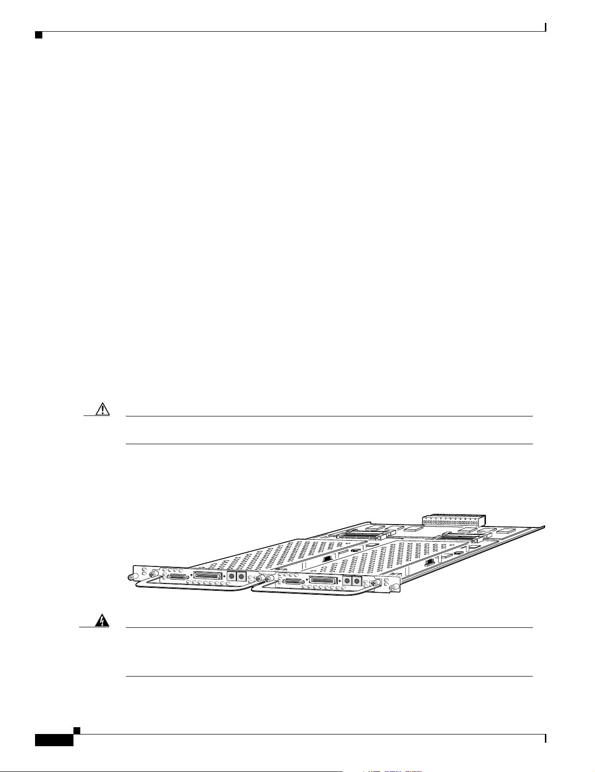
Each DFC carrier card accepts two DFCs which allow online insertion and removal (OIR). (See
Figure 2-1.)
Each DFC is a 5.1 x 13 inch PCI based interface board. The following is a brief description of the trunk
types supported:
• North American robbed-bit signaling (RBS) is supported on T1 trunks, including a variety of North
American RBS protocol, framing, and encoding types on these trunks.
• CAS is supported for E1 trunks, with R2 signaling.
• Many countries require an E1 R2 variant. Per-country defaults are provided for supervisory and
inter-register signaling.
• The CT3 DFC provides physical line termination for a channelized T3 ingress trunk line, and it uses
an onboard multiplexer to multiplex 28 channelized T1 lines into a single channelized T3 line.
Cisco AS5350 and Cisco AS5400 Universal Gateway Card Installation Guide
2-1
Page 20
Chapter 2 Dial Feature Card and Carrier Card Guidelines
Online Insertion and Removal (OIR) of DFCs
• Universal access (analog modem or digital calls) is supported when an interface is configured for
ISDN PRI signaling. PRI signaling is available for both T1 and E1 trunks.
In any single DFC slot, you can install your choice of:
• One T1, E1, or T3 dial feature card
• One universal port card
Online Insertion and Removal (OIR) of DFCs
All DFCs on the Cisco AS5350 and Cisco AS5400 chassis support online insertion and removal (also
known as hot swapping). You can install, remove, replace, and rearrange the DFCs without turning off
the chassis power.
When the chassis detects that a DFC is installed or removed, it automatically runs diagnostic and
discovery routines, acknowledges the presence or absence of the DFC, and resumes chassis operation
without any operator intervention.
See:
• Chapter 3, “T1 and E1 Dial Feature Cards,” to perform OIR of the T1 or E1 DFC.
• Chapter 4, “T3 Dial Feature Card,” to perform OIR of the T3 DFC.
• Chapter 5, “Universal Port Dial Feature Card,” to perform OIR of the universal port DFC.
Removing and Installing Populated Carrier Cards
Caution The carrier cards that carry the DFCs are not hot swappable. Removing a card while the system is
still powered on may cause permanent damage to electronic circuits on the card.
The DFC carrier card plugs into one of the backplane slots and supports two DFCs. The carrier card
increases backplane capacity and allows OIR of the DFCs. (See Figure 2-1.)
Figure 2-1 Carrier Card With Two 8 PRI CT1 Cards
29032
2-2
Warning
Cisco AS5350 and Cisco AS5400 Universal Gateway Card Installation Guide
Before working on a chassis or working near power supplies, unplug the power cord on AC units;
disconnect the power at the circuit breaker on DC units. To see translations of the warnings that
appear in this publication, refer to the Regulatory Compliance and Safety Information document
that accompanied this device.
78-13311-01
Page 21
Chapter 2 Dial Feature Card and Carrier Card Guidelines
Removing and Installing Populated Carrier Cards
Warning
Before performing any of the following procedures, ensure that power is removed from the DC
circuit. To ensure that all power is OFF, locate the circuit breaker on the panel board that services
the DC circuit, switch the circuit breaker to the OFF position, and tape the switch handle of the
circuit breaker in the OFF position. To see translations of the warnings that appear in this
publication, refer to the Regulatory Compliance and Safety Information document that
accompanied this device.
Caution Before you remove a carrier card, read Chapter 1, “Safety Warnings, Recommendations, and Tools
Required”
Removing a Populated Carrier Card
Warning
Warning
Before opening the chassis, disconnect the telephone-network cables to avoid contact with
telephone-network voltages. To see translations of the warnings that appear in this publication,
refer to the Regulatory Compliance and Safety Information document that accompanied this
device.
Do not work on the system or connect or disconnect cables during periods of lightning activity. To
see translations of the warnings that appear in this publication, refer to the Regulatory
Compliance and Safety Information document that accompanied this device.
To remove a populated carrier card, follow the steps below:
Step 1 Power off the chassis.
Step 2 Disconnect all interface cables from the universal gateway and secure them out of the way.
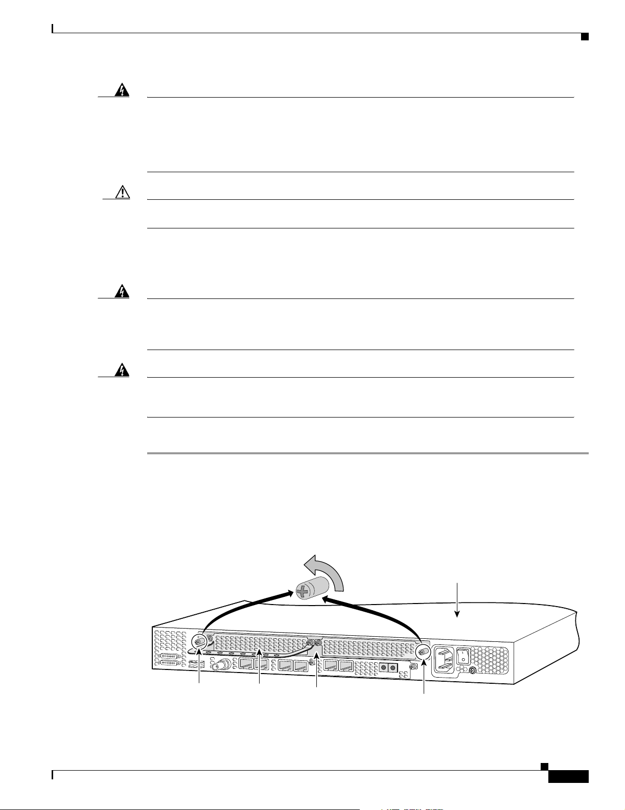
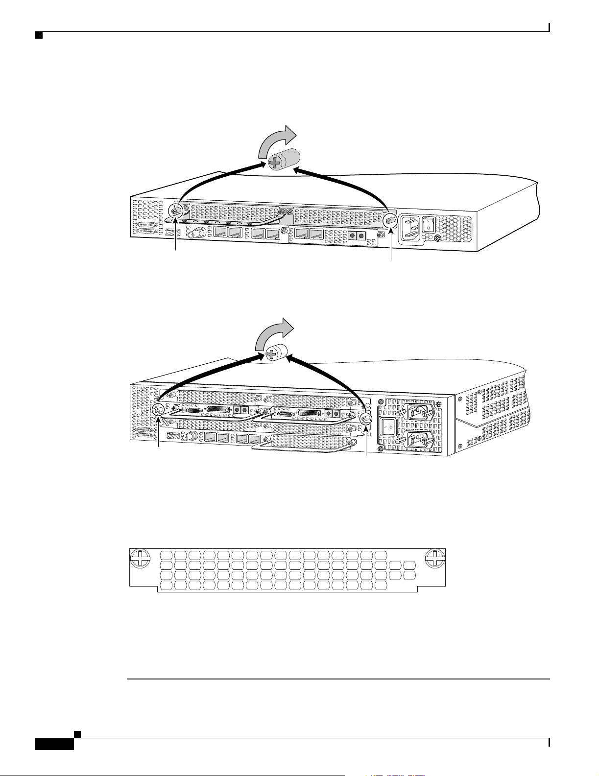
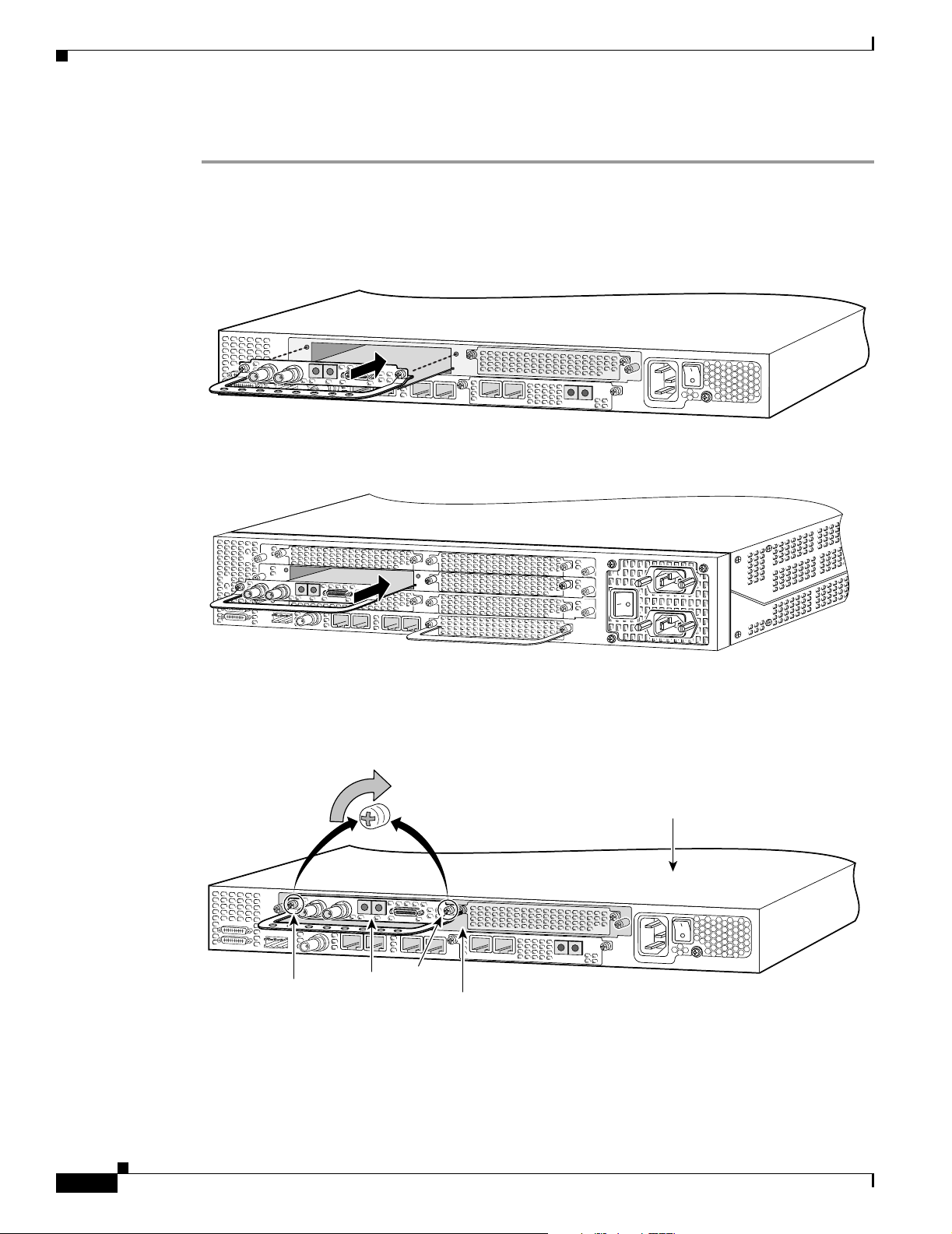
Step 3 Loosen the two captive screws that secure the carrier card to the chassis until each screw is free of the
chassis. (See Figure 2-2 and Figure 2-3.)
Figure 2-2 Loosen the Captive Screws on the Cisco AS5350
Chassis
36002
Captive screw
DFC
Carrier card
Captive screw
78-13311-01
Cisco AS5350 and Cisco AS5400 Universal Gateway Card Installation Guide
2-3
Page 22
Removing and Installing Populated Carrier Cards
Figure 2-3 Loosen the Captive Screws on the Cisco AS5400
Chapter 2 Dial Feature Card and Carrier Card Guidelines
Chassis
37159
Captive
screw
DFC
Carrier
card
DFC
Captive
screw
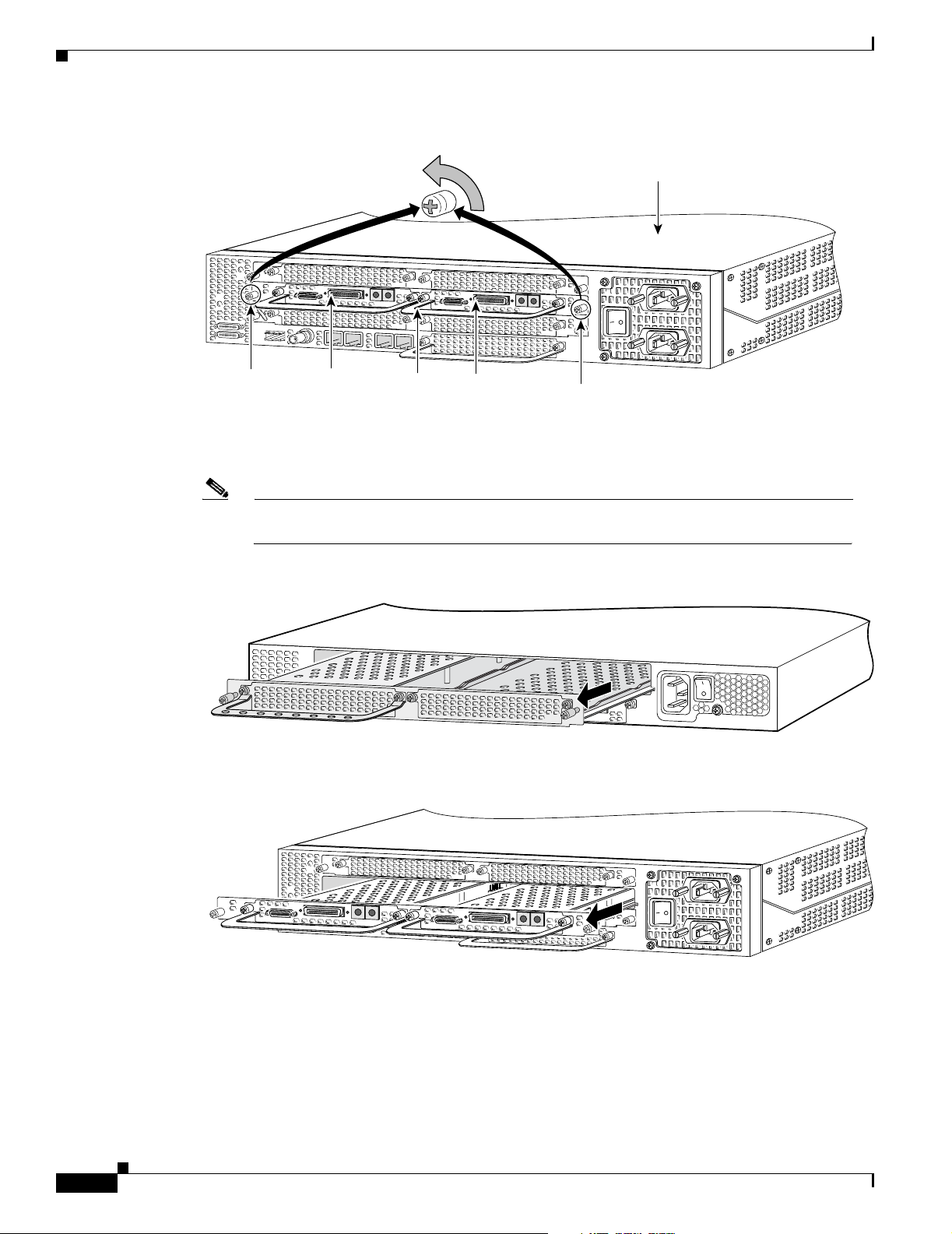
Step 4 Grasp the DFC handles and gently pull toward you to guide the carrier card out of the slot. Place one
hand under the carrier card as you pull it out of the chassis. (See Figure 2-4 and Figure 2-5.)
Note Use the DFC handles to remove the carrier card. Ensure that the DFCs are secured to the
carrier card.
Figure 2-4 Removing the Carrier Card from the Cisco AS5350
Figure 2-5 Removing the Carrier Card from the Cisco AS5400
36003
2-4
37160
Step 5 After you remove the carrier card from the chassis, set it aside on an ESD-preventive mat.
Cisco AS5350 and Cisco AS5400 Universal Gateway Card Installation Guide
78-13311-01
Page 23
Chapter 2 Dial Feature Card and Carrier Card Guidelines
Step 6 If the backplane slot is to remain empty, install a blank cover over the open slot to ensure proper airflow
inside the chassis. (See Figure 2-6.)
Figure 2-6 Blank Filler Panel
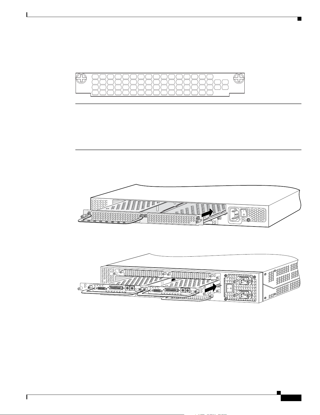
Installing a Populated Carrier Card
To install a populated carrier card:
Step 1 Slide the carrier card into the slot until it touches the backplane connector. (See Figure 2-7 and
Figure 2-8.)
Removing and Installing Populated Carrier Cards
36033
Figure 2-7 Install the Carrier Card in the Cisco AS5350
Figure 2-8 Install the Carrier Card in the Cisco AS5400
Step 2 Align the captive screws with their holes, and seat the card completely.
36004
37161
78-13311-01
Cisco AS5350 and Cisco AS5400 Universal Gateway Card Installation Guide
2-5
Page 24
Removing and Installing Populated Carrier Cards
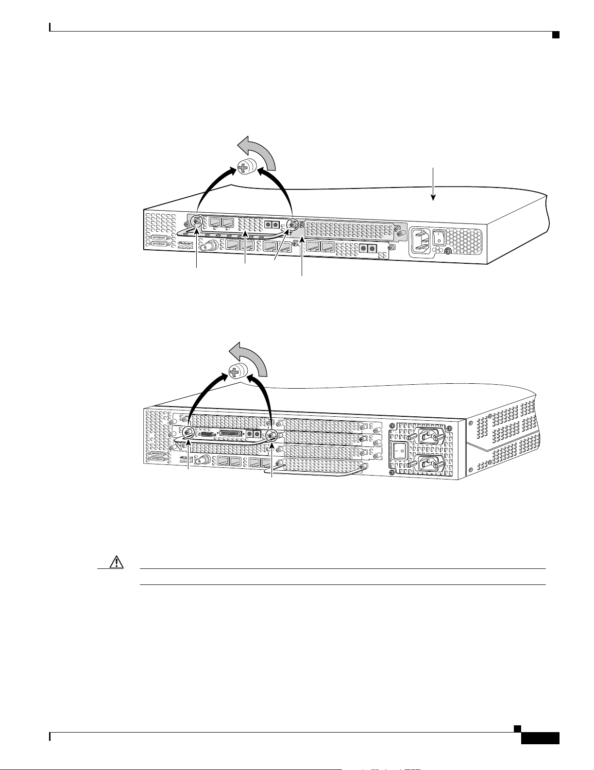
Step 3 Tighten the two captive screws to secure the carrier card to the chassis. (See Figure 2-9 and Figure 2-10.)
Figure 2-9 Tighten the Captive Screws on the Cisco AS5350
Captive screw
Figure 2-10 Tighten the Captive Screws on the Cisco AS5400
Chapter 2 Dial Feature Card and Carrier Card Guidelines
36005
Captive screw
Captive
screw
Step 4
If the carrier card has a blank DFC slot, install a blank cover over the open DFC slot to ensure proper
airflow inside the chassis. (See Figure 2-11.)
Figure 2-11 Blank DFC Cover
Step 5
For AC powered units, reconnect the AC power cord. For DC powered units, remove the tape from the
circuit breaker switch handle, and reinstate power by moving the handle of the circuit breaker to the ON
position. For more information on the AC and DC power supplies, refer to the chassis installation guide
that came with your universal gateway.
Step 6 Reconnect all interface cables.
37162
Captive
screw
36033
2-6
Cisco AS5350 and Cisco AS5400 Universal Gateway Card Installation Guide
78-13311-01
Page 25

Chapter 2 Dial Feature Card and Carrier Card Guidelines
Getting Help
For information about technical support, onsite service, and exchange and repair services, refer to the
“Obtaining Technical Assistance” section on page -xii in the “Preface.”
Where to Go Next
For instructions on installing and removing dial feature cards, refer to:
• Chapter 3, “T1 and E1 Dial Feature Cards.”
• Chapter 4, “T3 Dial Feature Card.”
• Chapter 5, “Universal Port Dial Feature Card.”
• Chapter 6, “Troubleshooting.”
• Appendix A, “Cabling Specifications.”
Getting Help
78-13311-01
Cisco AS5350 and Cisco AS5400 Universal Gateway Card Installation Guide
2-7
Page 26

Where to Go Next
Chapter 2 Dial Feature Card and Carrier Card Guidelines
2-8
Cisco AS5350 and Cisco AS5400 Universal Gateway Card Installation Guide
78-13311-01
Page 27
Overview
CHAPTER
3
T1 and E1 Dial Feature Cards
This chapter describes the installation and removal procedures for the T1 and E1 dial feature cards
(DFC) and includes the following sections:
• Overview, page 3-1
• Online Installation and Removal of the T1 or E1 DFC, page 3-3
• Configuring Input Impedance for the E1 DFC, page 3-11
• Getting Help, page 3-14
• Where to Go Next, page 3-14
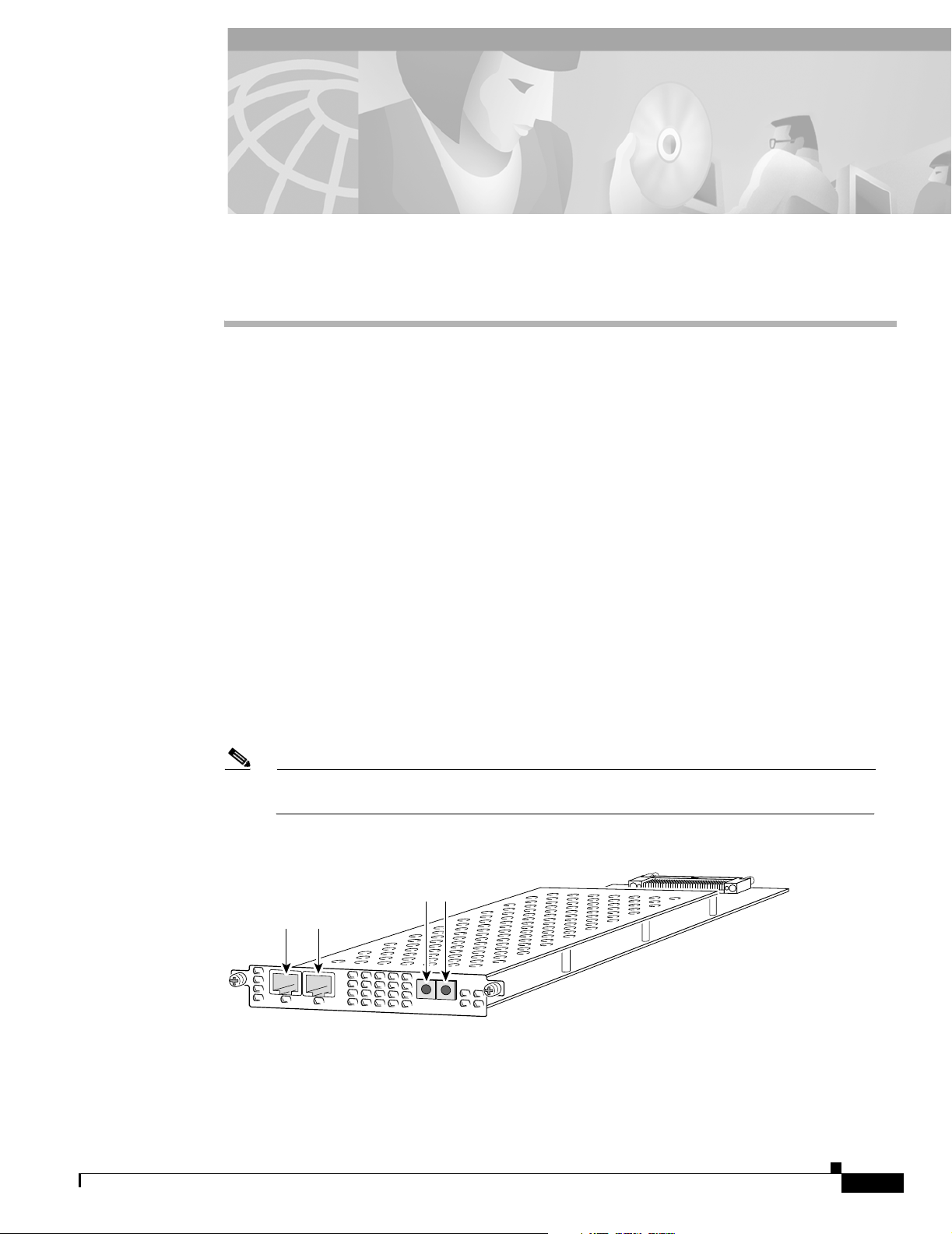
You can install a T1 or E1 dial feature card in any dial feature card slot of the universal gateway chassis.
(See Figure 3-1 through Figure 3-3.)
Each T1 or E1 DFC provides physical line termination for multiple DS-0 channels and uses onboard
HDLC controllers to terminate digital (ISDN) calls. For network specifications see Tab l e 3-1 and
Table 3-2. You can use the bantam ports on the DFC to monitor a line.
Note The Cisco AS5350 and Cisco AS5400 support only one type of WAN DFC at a time. Refer
to Chapter 6, “Troubleshooting” for more information.
Figure 3-1 2-Port T1 or E1 DFC
Bantam ports
T1 or E1 ports
0
1
2
P
R
I
Rx
Tx
ACT
OK
35840
78-13311-01
Cisco AS5350 and Cisco AS5400 Universal Gateway Card Installation Guide
3-1
Page 28

Overview
Figure 3-2 4-Port T1 or E1 DFC
Bantam ports
T1 or E1 ports
0
1
2
3
Rx
Figure 3-3 8-Port T1 or E1 DFC
Chapter 3 T1 and E1 Dial Feature Cards
56023
4
P
R
I
ACT
OK/
Tx
MAINT
Table 3-1 T1 DFC Network Specifications
Description Specification
Line rate 1.544 Mbps
Data rates (per port) number x 56 or number x 64 kbps, where
number = 1 to 24
Standards AT&T Pub. 62411, 54016, and 43081,
and ANSI T1.403
Input impedance 100 ohms per port
Table 3-2 E1 DFC Network Specifications
Description Specification
Line rate 2.048 Mbps
Data rate (per port) number x 56 or number x 64 kbps, where number = 1 to 31.
Input impedance 75 or 120 ohms per port
Note The factory default setting for the E1 ports is 120 ohm. Use a software
command to change the impedance. Refer to the, Cisco AS5350 and
Cisco AS5400 Universal Gateway Card Installation Guide.
29030
3-2
Cisco AS5350 and Cisco AS5400 Universal Gateway Card Installation Guide
78-13311-01
Page 29

Chapter 3 T1 and E1 Dial Feature Cards
Online Installation and Removal of the T1 or E1 DFC
Online Installation and Removal of the T1 or E1 DFC
Overview
To remove a DFC without dropping any calls or connections, you will need to take the DFC out of service
by using the busyout command to disable the DFC. The busyout command is executed on a per DFC
basis and will gracefully disable the card by waiting for the active services to terminate.
If you have active calls on the DFC after executing the busyout command, wait for the calls to drop. Use
the show busyout command to view the status of the termination process.
Caution The online installation and removal (OIR) of new cards should be done ONLY during times of low
CPU utilization, such as during maintenance.
Caution To avoid erroneous failure messages, remove or insert only one DFC at a time.
When you replace a DFC with a new DFC of the same type in the same slot, the system software will
recognize the new trunk interfaces and bring them up automatically.
If you replace the existing DFC with a new DFC of a different type, you will have to reconfigure the
system. For configuration details, refer to the Cisco AS5350 and Cisco AS5400 Universal Gateway
Software Configuration Guide.
Removing the T1 or E1 DFC
To remove the T1 or E1 DFC, follow these steps:
Note Following these steps are examples of the output from each command.
Step 1 Determine which slot the DFC is in by entering the show chassis command in privileged EXEC mode:
Router# show chassis slot
Figure 3-4 Slot Numbering on the Cisco AS5350 Chassis
78-13311-01
Slot 2
Slot 0
Slot 1
Cisco AS5350 and Cisco AS5400 Universal Gateway Card Installation Guide
Slot 3
36006
3-3
Page 30

Online Installation and Removal of the T1 or E1 DFC
Figure 3-5 Slot Numbering on the Cisco AS5400 Chassis
Chapter 3 T1 and E1 Dial Feature Cards
34977
Slot 1Slot 0
Step 2
Slot 2
Slot 4
Slot 6
Initialize the software busyout procedure by entering the busyout command:
Router# busyout slot-number
Slot 3
Slot 5
Slot 7
Step 3 Enter the show busyout command to check busyout status for that specific slot:
Router# show busyout slot-number
Step 4 You may use the clear port command to immediately disable active calls on the universal port card
(UPC). For more information on the UPC, see Chapter 5, “Universal Port Dial Feature Card”. Use the
show controller command to show the universal port card associated with the T1 or E1 DFC.
Router# show controller t1/e1 slot-number/control-number timeslot timeslot-number
Router# clear port slot-number/port number
Note The clear port command only applies to the universal port DFC.
Step 5 Verify that the OIR/MAINT LED is off; this indicates that the DFC is offline and ready to be removed.
Note The OK/MAINT LED is green before you enter the busyout command. After you enter the
busyout command, the LED changes to yellow. The LED turns off after all calls are
disconnected and resources are taken out of service, indicating that busyout is complete.
3-4
Step 6 Attach an ESD-preventive wrist strap.
Warning
Do not work on the system or connect or disconnect cables during periods of lightning activity. To
see translations of the warnings that appear in this publication, refer to the Regulatory
Compliance and Safety Information document that accompanied this device.
Step 7 Disconnect all interface cables from the DFC and secure them out of the way.
Cisco AS5350 and Cisco AS5400 Universal Gateway Card Installation Guide
78-13311-01
Page 31
Chapter 3 T1 and E1 Dial Feature Cards
Step 8 Loosen the two captive screws that secure the DFC to the chassis until each screw is free of the chassis.
(See Figure 3-6 and Figure 3-7.)
Figure 3-6 Loosen the Captive Screws on the Cisco AS5350
Online Installation and Removal of the T1 or E1 DFC
Chassis
2
P
R
0
1
I
R
x
T
x
A
C
T
O
K
Step 9
36814
Captive
screw
DFC
Captive
screw
Carrier
card
Figure 3-7 Loosen the Captive Screws on the Cisco AS5400
Captive
screw
Captive
screw
37163
Grasp the DFC handle with one hand and pull the card toward you until the card slides free of the chassis.
Grasp the ventilated metal cover with your other hand to support and guide the DFC out of the slot. (See
Figure 3-8 and Figure 3-9.)
78-13311-01
Caution Avoid touching any pins or circuit board components during removal and installation of a DFC.
Cisco AS5350 and Cisco AS5400 Universal Gateway Card Installation Guide
3-5
Page 32

Online Installation and Removal of the T1 or E1 DFC
Figure 3-8 Remove the DFC from the Cisco AS5350
0
1
Figure 3-9 Remove the DFC from the Cisco AS5400
Chapter 3 T1 and E1 Dial Feature Cards
2
P
R
I
R
x
T
x
ACT
OK
36815
37164
Step 10
After you remove the DFC from the chassis, set it aside on an ESD-preventive mat.
Step 11 If the DFC slot is to remain empty, install a blank cover over the open DFC slot to ensure proper airflow
inside the chassis. (See Figure 3-10.)
Figure 3-10 Blank DFC Cover
36033
The following output is an example of online insertion and removal of a E1 DFC in slot 6 of the
Cisco AS5400:
Router# show chassis slot 6
Slot 6:
DFC type is E1 8 PRI DFC
OIR events:
Number of insertions = 0, Number of removals = 0
DFC State is DFC_S_OPERATIONAL
3-6
Router#
Router# busyout 6
Busyout in progress for 6
Router# show busyout 6
Busyout status for trunk DFC slot = 6:
DFC slot busyout is in progress
(p - pending, s - static(cfg/exec), d - dynamic, n - none)
6/0 :s s p p p p p p p p p p p p p n p p p p p p p p p p p p p p p
Cisco AS5350 and Cisco AS5400 Universal Gateway Card Installation Guide
78-13311-01
Page 33

Chapter 3 T1 and E1 Dial Feature Cards
6/1 :s s s p p p p p p p p p p p p n p p p p p p p p p p p p p p p
6/2 :s s s p p p p p p p p p p p p n p p p p p p p p p p p p p p p
6/3 :s s s s p p p p p p p p p p p n p p p p p p p p p p p p p p p
6/4 :s s s p p p p p p p p p p p p n p p p p p p p p p p p p p p p
6/5 :s s s p p p p p p p p p p p p n p p p p p p p p p p p p p p p
6/6 :s s s p p p p p p p p p p p p n p p p p p p p p p p p p p p p
6/7 :s s p p p p p p p p p p p p p n p p p p p p p p p p p p p p p
Router#
Router# show controller e1 6/0 timeslot 1-31
E1 6/0 is up:
DS0 Type Modem Status rxA rxB rxC rxD txA txB txC txD
1 pri - idle
2 pri - idle
3 pri-modem 1/70 active
4 pri-modem 1/46 active
5 pri-modem 1/22 active
6 pri-modem 4/61 active
7 pri-modem 4/53 active
8 pri-modem 4/45 active
9 pri-modem 4/37 active
10 pri-modem 4/29 active
11 pri-modem 4/21 active
12 pri-modem 4/13 active
13 pri-modem 4/05 active
14 pri-modem 2/105 active
15 pri-modem 2/97 active
16 pri-D channel - 17 pri-modem 2/89 active
18 pri-modem 2/81 active
19 pri-modem 2/73 active
20 pri-modem 2/65 active
21 pri-modem 2/57 active
22 pri-modem 2/49 active
23 pri-modem 2/41 active
24 pri-modem 2/33 active
25 pri-modem 2/25 active
26 pri-modem 2/17 active
27 pri-modem 2/09 active
28 pri-modem 2/01 active
29 pri-modem 1/107 active
30 pri-modem 1/99 active
31 pri-modem 1/91 active
Router#
Router# show busyout 6
Busyout status for trunk DFC slot = 6:
DFC slot busyout is in progress
(p - pending, s - static(cfg/exec), d - dynamic, n - none)
Online Installation and Removal of the T1 or E1 DFC
78-13311-01
6/0 :s s p p p p p p p p p p p p p n p p p p p p p p p p p p p p p
6/1 :s s s p p p p p p p p p p p p n p p p p p p p p p p p p p p p
6/2 :s s s p p p p p p p p p p p p n p p p p p p p p p p p p p p p
6/3 :s s s s p p p p p p p p p p p n p p p p p p p p p p p p p p p
6/4 :s s s p p p p p p p p p p p p n p p p p p p p p p p p p p p p
6/5 :s s s p p p p p p p p p p p p n p p p p p p p p p p p p p p p
6/6 :s s s p p p p p p p p p p p p n p p p p p p p p p p p p p p p
6/7 :s s p p p p p p p p p p p p p n p p p p p p p p p p p p p p p
Router# clear port 1/70
This will clear port 1/70[confirm]
*Jan 1 00:27:37.083:%PORT-6-SM_PORT_CLEARED:Port 1/70 Cleared
Cisco AS5350 and Cisco AS5400 Universal Gateway Card Installation Guide
3-7
Page 34

Online Installation and Removal of the T1 or E1 DFC
Router# show busyout 6
Busyout status for trunk DFC slot = 6:
DFC slot busyout is in progress
(p - pending, s - static(cfg/exec), d - dynamic, n - none)
6/0 :s s s s s s s s s s p p p p p n p p p p p p p p p p p p p p p
6/1 :s s s p p p p p p p p p p p p n p p p p p p p p p p p p p p p
6/2 :s s s p p p p p p p p p p p p n p p p p p p p p p p p p p p p
6/3 :s s s s p p p p p p p p p p p n p p p p p p p p p p p p p p p
6/4 :s s s p p p p p p p p p p p p n p p p p p p p p p p p p p p p
6/5 :s s s p p p p p p p p p p p p n p p p p p p p p p p p p p p p
6/6 :s s s p p p p p p p p p p p p n p p p p p p p p p p p p p p p
6/7 :s s p p p p p p p p p p p p p n p p p p p p p p p p p p p p p
Router#
Router#
*Jan 1 00:32:40.271:%PORT-6-SM_PORT_CLEARED:All Ports Are Cleared
*Jan 1 00:32:40.635:%OIR-6-REMCARD:Card removed from slot 6, interfaces disabled
*Jan 1 00:32:40.643:%TRUNK_CLOCK-6-SWITCH:Switching to the clock on slot 7 port 0
priority 214 as the current primary has gone bad
*Jan 1 00:32:40.647:%CSM-5-PRI:delete PRI at slot 6, unit 0, channel 15 with index 0
*Jan 1 00:32:40.655:%CSM-5-PRI:delete PRI at slot 6, unit 1, channel 15 with index 1
*Jan 1 00:32:40.663:%CSM-5-PRI:delete PRI at slot 6, unit 2, channel 15 with index 2
*Jan 1 00:32:40.667:%CSM-5-PRI:delete PRI at slot 6, unit 3, channel 15 with index 3
*Jan 1 00:32:40.675:%CSM-5-PRI:delete PRI at slot 6, unit 4, channel 15 with index 4
*Jan 1 00:32:40.683:%CSM-5-PRI:delete PRI at slot 6, unit 5, channel 15 with index 4
*Jan 1 00:32:40.687:%CSM-5-PRI:delete PRI at slot 6, unit 6, channel 15 with index 3
*Jan 1 00:32:40.695:%CSM-5-PRI:delete PRI at slot 6, unit 7, channel 15 with index 2
Router#
*Jan 1 00:32:48.515:%ISDN-6-LAYER2DOWN:Layer 2 for Interface Se6/4:15, TEI 0 changed to
down
*Jan 1 00:32:48.523:%ISDN-6-LAYER2DOWN:Layer 2 for Interface Se6/5:15, TEI 0 changed to
down
*Jan 1 00:32:48.523:%ISDN-6-LAYER2DOWN:Layer 2 for Interface Se6/0:15, TEI 0 changed to
down
*Jan 1 00:32:48.523:%ISDN-6-LAYER2DOWN:Layer 2 for Interface Se6/3:15, TEI 0 changed to
down
*Jan 1 00:32:48.523:%ISDN-6-LAYER2DOWN:Layer 2 for Interface Se6/6:15, TEI 0 changed to
down
*Jan 1 00:32:48.527:%ISDN-6-LAYER2DOWN:Layer 2 for Interface Se6/7:15, TEI 0 changed to
down
*Jan 1 00:32:48.527:%ISDN-6-LAYER2DOWN:Layer 2 for Interface Se6/1:15, TEI 0 changed to
down
Router#
Router# show chassis slot 6
Chapter 3 T1 and E1 Dial Feature Cards
3-8
Slot 6:
DFC type is Empty DFC
DFC is not powered
OIR events:
Number of insertions = 0, Number of removals = 1
Router#
Router# show chassis slot 6
Slot 6:
DFC type is E1 8 PRI DFC
OIR events:
Number of insertions = 1, Number of removals = 1
DFC State is DFC_S_OPERATIONAL
Cisco AS5350 and Cisco AS5400 Universal Gateway Card Installation Guide
78-13311-01
Page 35

Chapter 3 T1 and E1 Dial Feature Cards
Installing the T1 or E1 DFC
Online Installation and Removal of the T1 or E1 DFC
Warning
Do not work on the system or connect or disconnect cables during periods of lightning activity. To
see translations of the warnings that appear in this publication, refer to the Regulatory
Compliance and Safety Information document that accompanied this device.
Warning
The E1 interface card may only be installed in an ACA-permitted customer equipment or a Data
Terminal Equipment (DTE) that is exempted from ACA's permit requirements. The customer
equipment must only be housed in a cabinet that has screw-down lids to stop user access to
overvoltages on the customer equipment. The customer equipment has circuitry that may have
telecommunications network voltages on them. To see translations of the warnings that appear in
this publication, refer to the Regulatory Compliance and Safety Information document that
accompanied this device.
Warning
The telecommunications lines must be disconnected 1) before unplugging the main power
connector and/or 2) while the housing is open. To see translations of the warnings that appear in
this publication, refer to the Regulatory Compliance and Safety Information document that
accompanied this device.
Note When you replace a DFC with a new DFC of the same type in the same slot, the system software will
recognize the new trunk interfaces and bring them up automatically. If you replace the existing DFC
with a new DFC of a different type, you will have to reconfigure the system. For configuration details,
refer to the Cisco AS5350 and Cisco AS5400 Universal Gateway Software Configuration Guide.
To install the T1 or E1 DFC, follow these steps:
Step 1 Attach an ESD preventive wrist strap.
Step 2 Slide the DFC into the slot until the connector pins make contact with the carrier card backplane
connector. (See Figure 3-11 and Figure 3-12.)
Figure 3-11 Install the T1 or E1 DFC in the Cisco AS5350
2
P
R
0
1
I
R
x
T
x
ACT
OK
36816
78-13311-01
Cisco AS5350 and Cisco AS5400 Universal Gateway Card Installation Guide
3-9
Page 36

Online Installation and Removal of the T1 or E1 DFC
Figure 3-12 Install the T1 or E1 DFC in the Cisco AS5400
Chapter 3 T1 and E1 Dial Feature Cards
37165
Step 3
Align the captive screws with their holes, and seat the card completely.
Step 4 Tighten the screws to secure the DFC to the chassis. (See Figure 3-13 and Figure 3-14.)
Figure 3-13 Tighten the Captive Screws on the Cisco AS5350
Chassis
2
P
R
R
x
T
x
A
Captive
screw
C
T
O
I
K
Carrier
Captive
screw
0
1
DFC
card
Figure 3-14 Tighten the Captive Screws on the Cisco AS5400
36817
3-10
Step 5
Captive
screw
Check the card LEDs to verify that the card is working properly. For information about dial feature card
Captive
screw
LEDs, refer to Chapter 6, “Troubleshooting”
Cisco AS5350 and Cisco AS5400 Universal Gateway Card Installation Guide
37163
78-13311-01
Page 37

Chapter 3 T1 and E1 Dial Feature Cards
Note For information about configuring the T1 or E1 ports, refer to the Cisco AS5350 and Cisco AS5400
Universal Gateway Software Configuration Guide.
Configuring Input Impedance for the E1 DFC
Use the line-termination command to set the input impedance for the E1 DFC.
You can set the input impedance before or after running the setup script. For information on configuring
the universal gateway with the setup script, refer to the Cisco AS5350 and Cisco AS5400 Universal
Gateway Software Configuration Guide.
Configuration
Command Purpose
Step 1
Step 2
Step 3
Step 4
Step 5
Router> enable
Password:
Router#
Router# configure terminal
Enter configuration commands, one per line.
End
with CNTL/Z.
Router(config)#
Router(config)# controller e1 0
Router(config-controller)#
Router(config-controller)# line-termination
75-ohm
Router(config-controller)# Ctrl-Z
Router#
%SYS-5-CONFIG_I: Configured from console by
console
password
Enter enable mode.
Enter the password.
You have entered enable mode when the
prompt changes to
Enter global configuration mode. You have
entered global configuration mode when the
prompt changes to
Enter the controller number to configure.
Sets the input impedance to 75 ohm for the
controller. The factory-set default is 120 ohm.
Repeat steps 3 and 4 for the other controllers.
Return to enable mode.
This message is normal and does not indicate
an error.
Configuring Input Impedance for the E1 DFC
Router#.
Router(config)#.
Verification
78-13311-01
To verify your impedance: Enter the show running-config command. Note that 120 ohms is the default
value and not displayed in the configuration file. The following output is an example of output after
having entered the command line-termination 75-ohm.
Router# show running-config
Building configuration...
Current configuration:
!
version 12.0
no service pad
service timestamps debug datetime msec localtime
Cisco AS5350 and Cisco AS5400 Universal Gateway Card Installation Guide
3-11
Page 38

Configuring Input Impedance for the E1 DFC
service timestamps log datetime localtime show-timezone
no service password-encryption
service internal
service udp-small-servers
service tcp-small-servers
!
hostname Router
!
boot system flash flash:1:vdukki/c5400-i-mz
enable secret 5 $1$qfO1$OYKRD2cvIJx7hfQbhrJS61
enable password lab
!
bert profile default pattern 220-O.151QRSS threshold 10^-6 error-injection none duration
10
ip subnet-zero
no ip domain-lookup
ip domain-name cisco.com
!
isdn switch-type primary-5ess
clock timezone PDT8 -8
clock summer-time PDT8 recurring
partition flash 2 8 8
!
!
!
controller E1 0
clock source free-running
line-termination 75-ohm
pri-group timeslots 1-31
!
controller E1 1
clock source line secondary 1
pri-group timeslots 1-31
!
controller E1 2
clock source line secondary 2
pri-group timeslots 1-31
!
controller E1 3
clock source line secondary 3
pri-group timeslots 1-31
!
controller E1 4
clock source line secondary 4
pri-group timeslots 1-3,16
!
controller E1 5
clock source line secondary 5
pri-group timeslots 1-31
!
controller E1 6
clock source line secondary 6
pri-group timeslots 1-31
!
controller E1 7
clock source line secondary 7
pri-group timeslots 1-31
!
!
!
interface Ethernet0
ip address 1.6.44.2 255.255.255.0
no ip directed-broadcast
no ip route-cache
Chapter 3 T1 and E1 Dial Feature Cards
3-12
Cisco AS5350 and Cisco AS5400 Universal Gateway Card Installation Guide
78-13311-01
Page 39

Chapter 3 T1 and E1 Dial Feature Cards
no ip mroute-cache
!
interface Serial0
ip address 1.1.1.1 255.255.255.0
no ip directed-broadcast
no keepalive
shutdown
no fair-queue
e2-clockrate
!
interface Serial1
no ip address
no ip directed-broadcast
no ip route-cache
no ip mroute-cache
shutdown
no fair-queue
clockrate 2015232
!
interface Serial2
no ip address
no ip directed-broadcast
no ip route-cache
no ip mroute-cache
shutdown
no fair-queue
clockrate 2015232
!
interface Serial3
no ip address
no ip directed-broadcast
no ip route-cache
no ip mroute-cache
shutdown
no fair-queue
clockrate 2015232
!
interface Serial0:15
no ip address
no ip directed-broadcast
isdn switch-type primary-5ess
no cdp enable
hold-queue 10 in
!
interface Serial1:15
no ip address
no ip directed-broadcast
isdn switch-type primary-5ess
no cdp enable
hold-queue 10 in
!
interface Serial2:15
no ip address
no ip directed-broadcast
isdn switch-type primary-5ess
no cdp enable
hold-queue 10 in
!
interface Serial3:15
no ip address
no ip directed-broadcast
isdn switch-type primary-5ess
no cdp enable
hold-queue 10 in
Configuring Input Impedance for the E1 DFC
78-13311-01
Cisco AS5350 and Cisco AS5400 Universal Gateway Card Installation Guide
3-13
Page 40

Getting Help
Chapter 3 T1 and E1 Dial Feature Cards
!
interface FastEthernet0
mac-address 0000.0c00.0011
ip address 15.0.0.1 255.0.0.0
no ip directed-broadcast
ip route-cache same-interface
no ip route-cache
no ip mroute-cache
no keepalive
duplex full
hold-queue 75 in
!
ip classless
ip route 223.255.254.254 255.255.255.255 Ethernet0
!
access-list 101 permit ip any any
access-list 101 deny igrp any any
dialer-list 1 protocol ip list 101
arp 25.0.0.1 1234.1234.1241 ARPA
arp 27.0.0.1 1234.1234.1243 ARPA
arp 26.0.0.1 1234.1234.1242 ARPA
arp 28.0.0.1 1234.1234.1244 ARPA
!
!
line con 0
exec-timeout 0 0
transport input none
line 1 54
line aux 0
transport input all
line vty 0 4
password lab
login
!
scheduler interval 500
end
Router#
Getting Help
For information about technical support, onsite service, and exchange and repair services, refer to the
“Obtaining Technical Assistance” section on page -xii in the “Preface.”
Where to Go Next
The remaining chapters of this guide include information on installing and troubleshooting DFCs and
creating cables.
• Chapter 4, “T3 Dial Feature Card.”
• Chapter 5, “Universal Port Dial Feature Card.”
• Chapter 6, “Troubleshooting.”
• Appendix A, “Cabling Specifications.”
3-14
Cisco AS5350 and Cisco AS5400 Universal Gateway Card Installation Guide
78-13311-01
Page 41
Overview
CHAPTER
4
T3 Dial Feature Card
This chapter describes the T3 dial feature card and includes the following sections:
• Overview, page 4-1
• Online Installation and Removal (OIR) of the T3 DFC, page 4-2
• Getting Help, page 4-7
• Where to Go Next, page 4-7
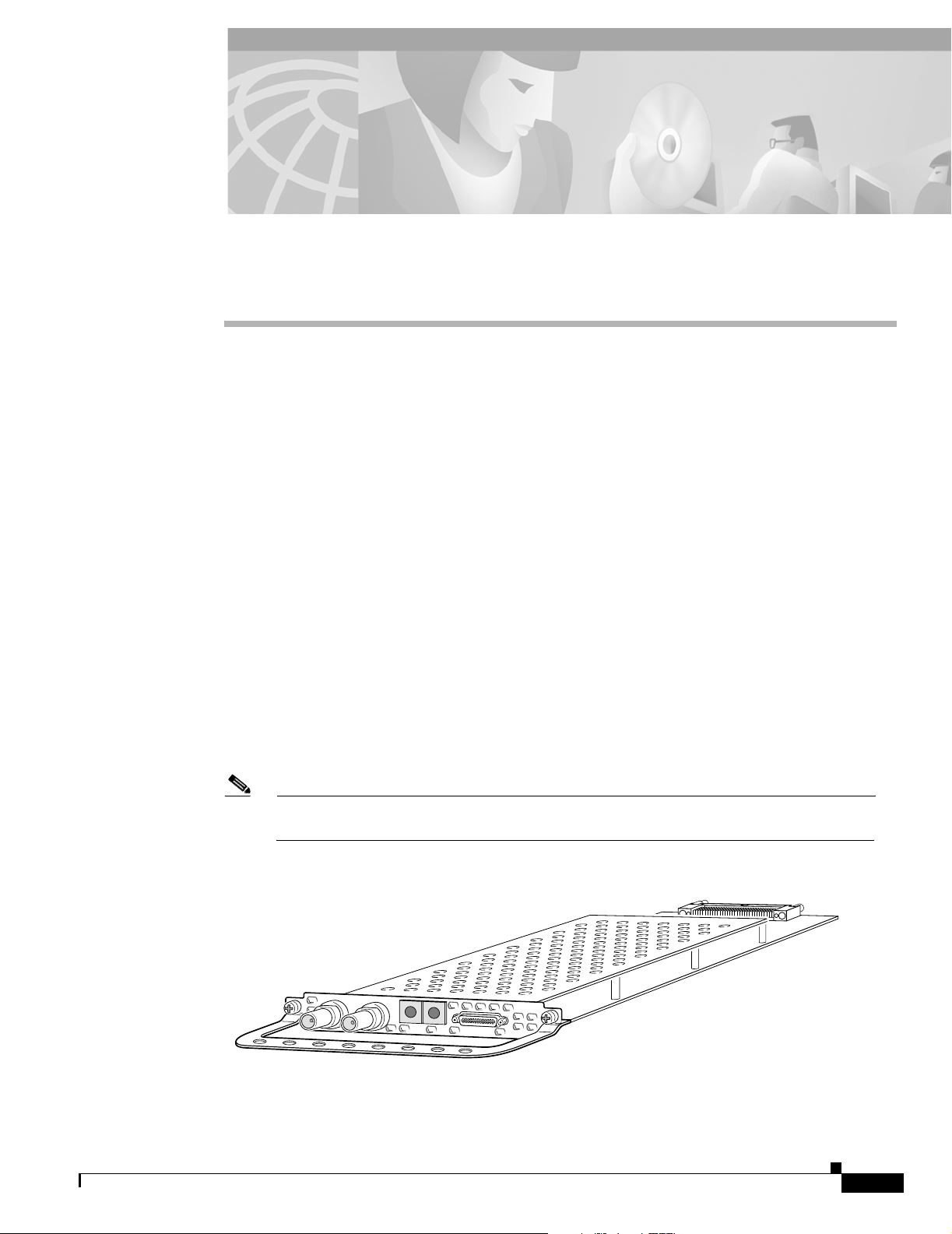
The T3 DFC provides physical line termination for a channelized T3 ingress trunk line. It uses an
onboard multiplexer to multiplex 28 channelized T1 lines into a single channelized T3 line. (See
Figure 4-1.)
The T3 DFC provides physical line termination for up to 672 DS0 channels and uses onboard HDLC
controllers to terminate digital (ISDN) calls.
You can use the bantam jacks on the DFC to monitor a T1 line or test any one of the individual T1 circuits
in drop and insert mode.
You can install a T3 DFC in any DFC slot of the universal gateway chassis.
Note The Cisco AS5350 and Cisco AS5400 support only one type of WAN DFC at a time. Refer
to Chapter 6, “Troubleshooting,” for more information.
Figure 4-1 T3 Dial Feature Card
29029
78-13311-01
Cisco AS5350 and Cisco AS5400 Universal Gateway Card Installation Guide
4-1
Page 42

Chapter 4 T3 Dial Feature Card
Online Installation and Removal (OIR) of the T3 DFC
Online Installation and Removal (OIR) of the T3 DFC
Overview
To remove a DFC without dropping any calls or connections, you will need to take the DFC out of service
by using the busyout command to disable the DFC. The busyout command is executed on a per DFC
basis and will gracefully disable the card by waiting for the active services to terminate.
If you have active calls on the DFC after executing the busyout command, wait for the calls to drop. Use
the show busyout command to view the status of the termination process.
Caution To avoid erroneous failure messages, remove or insert only one DFC at a time.
When you replace a DFC with a new DFC of the same type in the same slot, the system software will
recognize the new trunk interfaces and bring them up automatically.
If you replace the existing DFC with a new DFC of a different type, you will have to reconfigure the
system. For configuration details, refer to the Cisco AS5350 and Cisco AS5400 Universal Gateway
Software Configuration Guide.
Removing the T3 DFC
To remove the T3 DFC, follow these steps:
Note Following these steps are examples of the output from each command.
Step 1 Determine which slot the DFC is in (See Figure 4-2 and Figure 4-3.) by entering the show chassis
command in privileged EXEC mode:
Router# show chassis slot
Figure 4-2 Slot Numbering on the Cisco AS5350 Chassis
Slot 2
Slot 0
Slot 1
Slot 3
36006
4-2
Cisco AS5350 and Cisco AS5400 Universal Gateway Card Installation Guide
78-13311-01
Page 43

Chapter 4 T3 Dial Feature Card
Figure 4-3 Slot Numbering on the Cisco AS5400 Chassis
Online Installation and Removal (OIR) of the T3 DFC
34977
Slot 1Slot 0
Step 2
Slot 2
Slot 4
Slot 6
Initialize the software busyout procedure by entering the busyout command:
Router# busyout slot-number
Slot 3
Slot 5
Slot 7
Step 3 Enter the show busyout command to check busyout status for that specific slot:
Router# show busyout slot-number
Step 4 You may use the clear port command to immediately disable active calls on the universal port card. Use
the show controller command to show the universal port card associated with the T1 or E1 DFC.
Router# show controller t1/e1 slot-number/control-number timeslot timeslot-number
Router# clear port slot-number/port number
Note The clear port command only applies to the universal port DFC.
Step 5 Verify that the OIR/MAINT LED is off; this indicates that the DFC is offline and ready to be removed.
Note The OK/MAINT LED is green before you enter the busyout command. After you enter the
busyout command, the LED changes to yellow. The LED turns off after all calls are
disconnected and resources are taken out of service, indicating that busyout is complete.
78-13311-01
Step 6 Attach an ESD-preventive wrist strap.
Warning
Do not work on the system or connect or disconnect cables during periods of lightning activity. To
see translations of the warnings that appear in this publication, refer to the Regulatory
Compliance and Safety Information document that accompanied this device.
Step 7 Disconnect all interface cables from the DFC and secure them out of the way.
Note OIR of the T3 DFC is similar to that of the T1 or E1 DFC. To see an example of the output
during online insertion and removal of an E1 DFC refer to Chapter 3, “T1 and E1 Dial
Feature Cards”
Cisco AS5350 and Cisco AS5400 Universal Gateway Card Installation Guide
4-3
Page 44

Online Installation and Removal (OIR) of the T3 DFC
Step 8 Loosen the two captive screws that secure the DFC to the chassis until each screw is free of the chassis.
(See Figure 4-4 and Figure 4-5.)
Figure 4-4 Loosen the Captive Screws on the Cisco AS5350
Chapter 4 T3 Dial Feature Card
Chassis
Step 9
58760
Captive
screw
DFC
Captive
screw
Carrier
card
Figure 4-5 Loosen the Captive Screws on the Cisco AS5400
Captive
screw
Captive
screw
37167
Grasp the DFC handle with one hand and pull the card toward you until the card slides free of the chassis.
Grasp the ventilated metal cover with your other hand to support and guide the DFC out of the slot. (See
Figure 4-6 and Figure 4-7.)
4-4
Caution Avoid touching any pins or circuit board components during removal and installation of the DFC.
Cisco AS5350 and Cisco AS5400 Universal Gateway Card Installation Guide
78-13311-01
Page 45

Chapter 4 T3 Dial Feature Card
Figure 4-6 Remove the DFC from the Cisco AS5350
Figure 4-7 Remove the DFC from the Cisco AS5400
Online Installation and Removal (OIR) of the T3 DFC
58761
Step 10
Step 11 If a DFC slot on the carrier card is to remain empty, install a blank cover over the open DFC slot to ensure
After you remove the DFC from the chassis, set it aside on an ESD-preventive mat.
proper airflow inside the chassis. (See Figure 4-8.)
Figure 4-8 Blank DFC Cover
Installing the T3 DFC
Warning
Do not work on the system or connect or disconnect cables during periods of lightning activity. To
see translations of the warnings that appear in this publication, refer to the Regulatory
Compliance and Safety Information document that accompanied this device.
37168
36033
78-13311-01
Note When you replace a DFC with a new DFC of the same type in the same slot, the system software will
recognize the new trunk interfaces and bring them up automatically. If you replace the existing DFC
with a new DFC of a different type, you will have to reconfigure the system. For configuration details,
refer to the Cisco AS5350 and Cisco AS5400 Universal Gateway Software Configuration Guide.
Cisco AS5350 and Cisco AS5400 Universal Gateway Card Installation Guide
4-5
Page 46
Online Installation and Removal (OIR) of the T3 DFC
To install the T3 DFC, follow these steps:
Step 1 Attach an ESD-preventive wrist strap.
Step 2 Slide the DFC into the slot until the connector pins make contact with the carrier card backplane
connector. (See Figure 4-9 and Figure 4-10.)
Figure 4-9 Install the T3 DFC in the Cisco AS5350
Figure 4-10 Install the T3 DFC in the Cisco AS5400
Chapter 4 T3 Dial Feature Card
58762
Step 3
Align the captive screws with their holes, and seat the card completely.
Step 4 Tighten the screws to secure the DFC to the chassis. (See Figure 4-11 and Figure 4-12.)
Figure 4-11 Tighten the Captive Screws on the Cisco AS5350
Chassis
Captive
Captive
screw
DFC
screw
Carrier
card
37169
58763
4-6
Cisco AS5350 and Cisco AS5400 Universal Gateway Card Installation Guide
78-13311-01
Page 47

Chapter 4 T3 Dial Feature Card
Figure 4-12 Tighten the Captive Screws on the Cisco AS5400
Getting Help
Captive
screw
Step 5
Check the card LEDs to verify that the card is working properly. For information about dial feature card
LEDs, refer to Chapter 6, “Troubleshooting”
Getting Help
For information about technical support, onsite service, and exchange and repair services, refer to the
“Obtaining Technical Assistance” section on page -xii in the “Preface.”
Where to Go Next
The remaining chapters of this guide include information on installing and troubleshooting DFCs and
creating cables.
• Chapter 5, “Universal Port Dial Feature Card.”
• Chapter 6, “Troubleshooting.”
• Appendix A, “Cabling Specifications.”
37170
Captive
screw
78-13311-01
Cisco AS5350 and Cisco AS5400 Universal Gateway Card Installation Guide
4-7
Page 48

Where to Go Next
Chapter 4 T3 Dial Feature Card
4-8
Cisco AS5350 and Cisco AS5400 Universal Gateway Card Installation Guide
78-13311-01
Page 49

Overview
CHAPTER
5
Universal Port Dial Feature Card
This chapter describes the universal port dial feature card (DFC) and includes the following sections:
• Overview, page 5-1
• Online Insertion and Removal (OIR) of the Universal Port DFC, page 5-2
• SPE Firmware, page 5-9
• Getting Help, page 5-9
• Where to Go Next, page 5-9
The universal port DFC provides multiple port sessions, with each session capable of originating or
terminating a session over a DS-0 in PCM format. The number of sessions depends on the port density
of the card. You can install a universal port DFC in any DFC slot of the universal gateway chassis. The
universal port DFC does not require external connections. (See Figure 5-1.)
78-13311-01
Figure 5-1 Universal Port DFC
31634
Cisco AS5350 and Cisco AS5400 Universal Gateway Card Installation Guide
5-1
Page 50

Chapter 5 Universal Port Dial Feature Card
Online Insertion and Removal (OIR) of the Universal Port DFC
Online Insertion and Removal (OIR) of the Universal Port DFC
Overview
To remove a DFC without dropping any calls or connections, you will need to take the DFC out of service
by using the busyout command to disable the DFC. The busyout command is executed on a per DFC
basis and will gracefully disable the card by waiting for the active services to terminate.
If you have active calls on the DFC after executing the busyout command, wait for the calls to drop. Use
the show busyout command to view the status of the termination process.
Caution To avoid erroneous failure messages, remove or insert only one DFC at a time.
When you replace a DFC with a new DFC of the same type in the same slot, the system software will
recognize the new trunk interfaces and bring them up automatically.
If you replace the existing DFC with a new DFC of a different type, you will have to reconfigure the
system. For configuration details, refer to the Cisco AS5350 and Cisco AS5400 Universal Gateway
Software Configuration Guide. For information on voice and fax commands, refer to the
Monitoring Voice and Fax Services on the Cisco AS5350 and Cisco AS5400 Universal Gateways online
document.
Removing the Universal Port DFC
To remove the universal port DFC, follow these steps:
Note Following these steps are examples of the output of each command.
Step 1 Determine which slot the DFC is in (see Figure 5-2 and Figure 5-3) by entering the show chassis
command in privileged EXEC mode:
Router# show chassis slot
Figure 5-2 Slot Numbering on the Cisco AS5350 Chassis
Slot 0
Slot 2
Slot 1
Slot 3
36006
5-2
Cisco AS5350 and Cisco AS5400 Universal Gateway Card Installation Guide
78-13311-01
Page 51

Chapter 5 Universal Port Dial Feature Card
Figure 5-3 Slot Numbering on the Cisco AS5400 Chassis
Online Insertion and Removal (OIR) of the Universal Port DFC
34977
Slot 1Slot 0
Step 2
Slot 2
Slot 4
Slot 6
Initialize the software busyout procedure by entering the busyout command:
Router# busyout slot-number
Slot 3
Slot 5
Slot 7
Step 3 Enter the show busyout command to check busyout status for that specific slot:
Router# show busyout slot-number
Step 4 You may use the clear port command to immediately disable active calls on the universal port card.
Router# clear port slot-number/port number
Step 5 Verify that the OIR/MAINT LED is off; this indicates that the DFC is offline and ready to be removed.
Note The OK/MAINT LED is green before you enter the busyout command. After you enter the
busyout command, the LED changes to yellow. The LED turns off after all calls are
disconnected and resources taken out of service, indicating that busyout is complete.
Step 6 Attach an ESD-preventive wrist strap.
Warning
Do not work on the system or connect or disconnect cables during periods of lightning activity. To
see translations of the warnings that appear in this publication, refer to the Regulatory
Compliance and Safety Information document that accompanied this device.
78-13311-01
Step 7 Disconnect all interface cables from the DFC.
Cisco AS5350 and Cisco AS5400 Universal Gateway Card Installation Guide
5-3
Page 52

Online Insertion and Removal (OIR) of the Universal Port DFC
Step 8 Loosen the two captive screws that secure the DFC to the chassis until each screw is free of the chassis.
(See Figure 5-4 and Figure 5-5.)
Figure 5-4 Loosen the Captive Screws on the Cisco AS5350
Chapter 5 Universal Port Dial Feature Card
Chassis
Step 9
36821
Captive
screw
DFC
Carrier card
Captive
screw
Figure 5-5 Loosen the Captive Screws on the Cisco AS5400
Captive
screw
Captive
screw
37171
Grasp the DFC handle with one hand and pull the card toward you until the card slides free of the chassis.
Grasp the ventilated metal cover with your other hand to support and guide the DFC out of the slot. (See
Figure 5-6 and Figure 5-7.)
5-4
Figure 5-6 Remove the DFC from the Cisco AS5350
36819
Cisco AS5350 and Cisco AS5400 Universal Gateway Card Installation Guide
78-13311-01
Page 53

Chapter 5 Universal Port Dial Feature Card
Figure 5-7 Remove the DFC from the Cisco AS5400
Caution Avoid touching any pins or circuit board components during removal and installation of a DFC.
Step 10 After you remove the DFC, set it aside on an ESD-preventive mat.
Step 11 If the DFC slot is to remain empty, install a blank cover over the open DFC slot to ensure proper airflow
inside the chassis. (See Figure 5-8.)
Online Insertion and Removal (OIR) of the Universal Port DFC
37172
Figure 5-8 Blank DFC Cover
36033
The following output is an example of online insertion and removal of a universal port DFC in slot 3:
Router# show chassis slot 3
Slot 3:
DFC type is NP108 DFC
OIR events:
Number of insertions = 0, Number of removals = 0
DFC State is DFC_S_OPERATIONAL
Router#
Router# show busyout 3
Slot 3 is not being busied out
Router#
Router# busyout 3
Busyout in progress for 3
Router#
Router# show busyout 3
Slot busyout is in progress
Slot 3:Pending (64 calls remaining)
Router#
Router# show chassis slot 3
78-13311-01
Slot 3:
DFC type is NP108 DFC
OIR events:
Number of insertions = 0, Number of removals = 0
DFC State is DFC_S_OPERATIONAL
Cisco AS5350 and Cisco AS5400 Universal Gateway Card Installation Guide
5-5
Page 54

Online Insertion and Removal (OIR) of the Universal Port DFC
Router#
Router# clear port 3
This will clear ports 3/00 - 3/107[confirm]
Router#
*Jan 1 00:14:22.555:%PORT-6-SM_PORT_CLEARED:Port 3/00 - 3/107 Cleared
Router# show busyout 3
Slot busyout is in progress
Slot 3:Pending (54 calls remaining)
Router#
Router# show busyout 3
Slot busyout is in progress
Slot 3:Pending (36 calls remaining)
Router# show busyout 3
Slot busyout is in progress
Slot 3:Pending (30 calls remaining)
Router# clear port 3
This will clear ports 3/00 - 3/107[confirm]
Router#
*JRouteran 1 00:14:59.275:%PORT-6-SM_PORT_CLEARED:Port 3/00 - 3/107 Cleared
Router# show busyout 3
Slot busyout is in progress
Slot 3:Pending (9 calls remaining)
Router# clear port 3
*Jan 1 00:15:10.355:%NP_MD-6-MODULE_DOWN:NextPort module 3/0/0 down
*Jan 1 00:15:10.363:%NP_BS-6-MODULE_STOPPED:NextPort module 3/0/0 Stopped
*Jan 1 00:15:10.363:%NP_MD-6-MODULE_DOWN:NextPort module 3/0/1 down
*Jan 1 00:15:10.371:%NP_BS-6-MODULE_STOPPED:NextPort module 3/0/1 Stopped
*Jan 1 00:15:10.371:%NP_MD-6-MODULE_DOWN:NextPort module 3/0/2 down
*Jan 1 00:15:10.379:%NP_BS-6-MODULE_STOPPED:NextPort module 3/0/2 Stopped
*Jan 1 00:15:10.379:%NP_MD-6-SLOT_REMOVED:Slot 3 removed
Router# clear port 3
*Jan 1 00:15:10.539:%OIR-6-REMCARD:Card removed from slot 3, interfaces disabled
Router# show chassis slot 3
Chapter 5 Universal Port Dial Feature Card
Slot 3:
DFC type is Empty DFC
DFC is not powered
OIR events:
Number of insertions = 0, Number of removals = 1
Router#
Router#
*Jan 1 00:16:29.047:%OIR-6-INSCARD:Card inserted in slot 3, interfaces administratively
shut down
*Jan 1 00:16:29.123:%NP_MD-6-SLOT_INSERTED:Slot 3 (108 ports max) inserted
Router#
*Jan 1 00:16:33.415:%NP_BS-6-MODULE_STARTED:NextPort module 3/0/0 Started - 1.1.3.77
Router#
*Jan 1 00:16:37.843:%NP_BS-6-MODULE_STARTED:NextPort module 3/0/1 Started - 1.1.3.77
*Jan 1 00:16:40.615:%NP_MD-6-MODULE_UP:NextPort module 3/0/0 up
Router#
*Jan 1 00:16:41.847:%NP_BS-6-MODULE_STARTED:NextPort module 3/0/2 Started - 1.1.3.77
Router#
5-6
Cisco AS5350 and Cisco AS5400 Universal Gateway Card Installation Guide
78-13311-01
Page 55

Chapter 5 Universal Port Dial Feature Card
Router# show chassis slot 3
Slot 3:
DFC type is NP108 DFC
OIR events:
Number of insertions = 1, Number of removals = 1
DFC State is DFC_S_OPERATIONAL
Installing the Universal Port DFC
Online Insertion and Removal (OIR) of the Universal Port DFC
Warning
Do not work on the system or connect or disconnect cables during periods of lightning activity. To
see translations of the warnings that appear in this publication, refer to the Regulatory
Compliance and Safety Information document that accompanied this device.
Note When you replace a DFC with a new DFC of the same type in the same slot, the system software will
recognize the new trunk interfaces and bring them up automatically. If you replace the existing DFC
with a new DFC of a different type, you will have to reconfigure the system. For configuration details,
refer to the Cisco AS5350 and Cisco AS5400 Universal Gateway Software Configuration Guide.
To install the universal port DFC, follow these steps:
Step 1 Attach an ESD preventive wrist strap.
Step 2 Slide the DFC into the slot until the connector pins make contact with the carrier card backplane
connector. (See Figure 5-9 and Figure 5-10.)
Figure 5-9 Install the Universal Port DFC in the Cisco AS5350
78-13311-01
Step 3
36820
Figure 5-10 Install the Universal Port DFC in the Cisco AS5400
37201
Align the captive screws with their holes, and then seat the card completely.
Cisco AS5350 and Cisco AS5400 Universal Gateway Card Installation Guide
5-7
Page 56

Online Insertion and Removal (OIR) of the Universal Port DFC
Step 4 Seat the DFC in the carrier by pushing the card firmly until the captive screws are aligned with their
holes.
Step 5 Tighten the screws to secure the DFC to the chassis. (See Figure 5-11 and Figure 5-12.)
Figure 5-11 Tighten the Captive Screws on the Cisco AS5350
Chapter 5 Universal Port Dial Feature Card
Chassis
Step 6
36818
Captive
screw
DFC
Carrier card
Captive
screw
Figure 5-12 Tighten the Captive Screws on the Cisco AS5400
Captive
screw
Captive
screw
37202
Check the card LEDs to verify that the card is working properly. For information about dial feature card
LEDs, refer to Chapter 6, “Troubleshooting”
5-8
Cisco AS5350 and Cisco AS5400 Universal Gateway Card Installation Guide
78-13311-01
Page 57

Chapter 5 Universal Port Dial Feature Card
SPE Firmware
SPE firmware is automatically downloaded to a universal port DFC from the Cisco IOS image when you
boot the system for the first time, or when you insert a universal port DFC while the system is operating.
When you insert DFCs while the system is operating, the Cisco IOS image recognizes the cards and
downloads the required firmware to the cards.
For more information on universal port software and upgrade options, refer to the Cisco AS5350 and
Cisco AS5400 Universal Gateway Software Configuration Guide.
For information on managing universal port services, refer to Managing Port Services on the Cisco 5350
Universal Gateway and Managing Port Services on the Cisco AS5400 Universal Gateway.
Getting Help
For information about technical support, onsite service, and exchange and repair services, refer to the
“Obtaining Technical Assistance” section on page -xii in the “Preface.”
SPE Firmware
Where to Go Next
The remaining chapters of this guide include information on troubleshooting DFCs and creating cables.
• Chapter 6, “Troubleshooting.”
• Appendix A, “Cabling Specifications.”
78-13311-01
Cisco AS5350 and Cisco AS5400 Universal Gateway Card Installation Guide
5-9
Page 58

Where to Go Next
Chapter 5 Universal Port Dial Feature Card
5-10
Cisco AS5350 and Cisco AS5400 Universal Gateway Card Installation Guide
78-13311-01
Page 59

LEDs
CHAPTER
6
Troubleshooting
This chapter describes how to troubleshoot the universal gateway by referring to the LEDs on DFCs, and
using the bantam jacks. The chapter contains the following sections:
• LEDs, page 6-1
• Mixing WAN DFCs, page 6-5
• Environment Monitoring, page 6-6
• Using the Bantam Jacks for Test Port Functionality, page 6-9
• Troubleshooting Network Interfaces, page 6-10
• Getting Help, page 6-10
The LEDs indicate the current operating condition of the dial feature cards. Observe the LEDs (see
Figure 6-1 through Figure 6-4), note any fault condition that the product is encountering, and then
contact your system administrator or a customer service representative (see “Obtaining Technical
Assistance” in the “Preface”), if necessary. Refer to Table 6 -1 for a description of the LEDs.
Figure 6-1 2-Port or 4-Port T1 or E1 DFC LEDs
0
1
35681
0
1
ACTIVITY (ACT)
OK/MAINT
78-13311-01
Cisco AS5350 and Cisco AS5400 Universal Gateway Card Installation Guide
6-1
Page 60
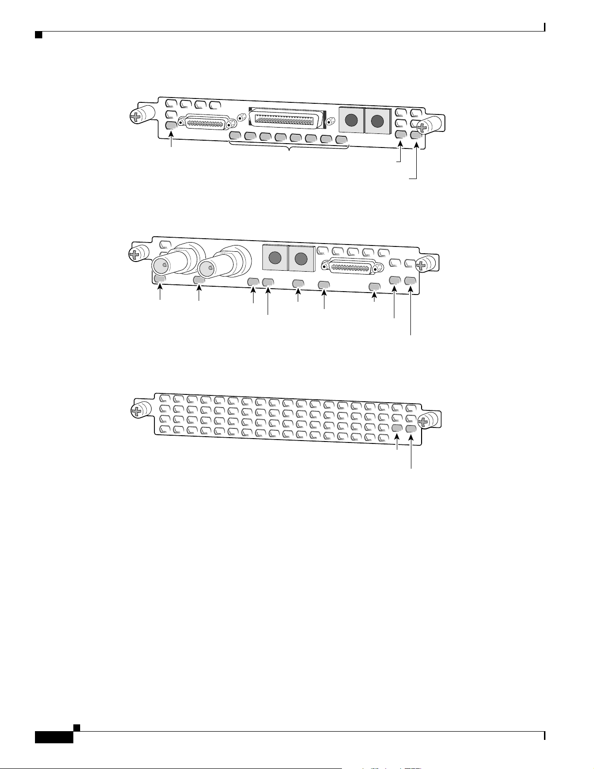
LEDs
Chapter 6 Troubleshooting
Figure 6-2 8-Port T1 or E1 DFC LEDs
LNK
Local alarm,
Remote alarm, or
Loopback LED for
each T1/E1 port
Figure 6-3 T3 DFC LEDs
Loop
LOS
EN/DIS
RA
Figure 6-4 Universal Port DFC LEDs
LA
ACTIVITY (ACT)
MA
ACTIVITY (ACT)
31630
OK/MAINT
31631
LNK
OK/MAINT
6-2
ACTIVITY (ACT)
31362
OK/MAINT
Cisco AS5350 and Cisco AS5400 Universal Gateway Card Installation Guide
78-13311-01
Page 61

Chapter 6 Troubleshooting
Ta b l e 6 - 1 L E D s
LEDs
DFC LED State Description
T1 or E1 DFC ACTIVITY (ACT) Fast flicker (Green) Indicates DFC is up and running.
Slow flicker (Green) Indicates DFC is not yet fully
functional.
OK/MAINT Green The T1 or E1 DFC has passed initial
power-up diagnostics tests and is
operating normally.
Yellow The T1 or E1 DFC is not functioning.
See the console for messages.
Off Indicates that all calls associated
with the card are shut down and it is
safe to remove the card with the
system powered on.
Remote Alarm
(RA), Local Alarm
(LA), or Loopback
(LB)
On (Yellow) One LED below each T1/E1 port
indicates one of the following:
• A local or remote loopback
diagnostic test is running on the
associated T1 port.
• An alarm is received on the
associated T1/E1 port, indicating
loss of signal (LOS) or loss of
multiframe alignment (LOF) at
the local or remote node.
78-13311-01
Cisco AS5350 and Cisco AS5400 Universal Gateway Card Installation Guide
6-3
Page 62

LEDs
Chapter 6 Troubleshooting
Table 6-1 LEDs (continued)
DFC LED State Description
T3 DFC ACTIVITY (ACT) Fast flicker Indicates DFC is up and running.
Slow flicker Indicates DFC is not yet fully
functional.
OK/MAINT On (Green) The CT3 DFC passed initial
power-up diagnostics tests and is
operating normally.
Yellow The CT3 DFC is not functioning. See
the console for messages.
Off Indicates that all calls associated
with the DFC are shut down and it is
safe to remove the card with the
system powered on.
M13 Alarm (MA) On Indicates the presence of one of the
following on the CT3 line:
Received Alarm Indication Signal
(RAIS), Loss Of Signal (LOS),
Receive RED Alarm (RRED), or a
Far-End Receive Failure(RFERF).
Off Remains off when operating
condition is normal.
Remote Alarm
(RA)
On Indicates a T1 alarm condition
encountered by software.
Off Remains off when operating
condition is normal.
Local Alarm (LA) On Indicates a T1 alarm condition
encountered by software for a
particular port.
Off Remains off when operating
condition is normal.
T3 EN/DIS Green Indicates a CT3 card line connection
enabling normal operation.
Yellow Normal operation is disabled.
Low signal (LOS) On Indicates the CT3 LIU is
experiencing a loss of signal.
Off Remains off when operating
condition is normal.
Network Loop
(LOOP)
On Indicates that at least one T1 is
unavailable.
Off Remains off when operating
condition is normal.
1
6-4
Cisco AS5350 and Cisco AS5400 Universal Gateway Card Installation Guide
78-13311-01
Page 63

Chapter 6 Troubleshooting
Table 6-1 LEDs (continued)
Mixing WAN DFCs
The Cisco AS5350 and Cisco AS5400 support only one type of WAN DFC at a time. The DFCs that can
be installed at one time are:
DFC LED State Description
Universal Port
DFC
ACTIVITY (ACT) Flickering There is call activity on the DFC.
OK/MAINT On The DFC passed the initial power-up
diagnostic tests and is operating
normally.
Off Indicates that all calls associated
with the card are shut down and it is
safe to remove the card with the
system powered on.
1. To display information about an M13 alarm, use the show CT3 EXEC command.
• Up to three T1 DFCs (any combination of 2, 4, or 8-port) or
• Up to three E1 DFCs (any combination of 2, 4, or 8-port) or
LEDs
• One CT3 DFC or
• One CT3 DFC and up to two T1 DFCs (any combination of 2, 4, or 8-port)
The universal gateway software recognizes DFCs in the order of the slots they are in. For example, a
DFC in slot 2 will be recognized before a DFC in slot 3. The system will recognize if there is a mix of
WAN DFCs during both power up and OIR:
• During power up, the first WAN DFC recognized by the system will be the only type brought up.
• If there are two or more WAN DFCs of the same type and one is hot-swapped with another of a
different type, the new one will not be recognized.
In both situations, an error message will appear on the console that is similar to:
00:01:12:%CARRIER-2-T1_E1_MIX:Cannot mix T1 and E1 8PRI DFC cards in chassis, do not power
up invalid card in slot 7
78-13311-01
Cisco AS5350 and Cisco AS5400 Universal Gateway Card Installation Guide
6-5
Page 64

Environment Monitoring
Environment Monitoring
Overview
The Cisco AS5350 and Cisco AS5400 contain temperature sensors to detect abnormal temperature
conditions during system operation. The three levels of sensor detection are as follows:
1. When the operating temperature of the system exceeds 45° C, the system reaches a warning state. A
warning message appears on the console. When the operating temperature of the system drops below
45° C, another message is displayed on the console indicating a recovery. At this level of sensor
detection, there is no disruption in system operation.
2. When the operating temperature of the system continues to rise above 45° C and reaches a
temperature of 60° C, the system reaches a critical state.
Cisco IOS software busys out the DFCs in the chassis and shuts down the first DFC. If the operating
temperature continues to be critical after 10 minutes, Cisco IOS software shuts down another DFC.
Chapter 6 Troubleshooting
Note DFC slot numbering starts from the system board and works up from left to right. Slot 0 is
reserved for the motherboard. The DFC slots are numbered sequentially. (See Figure 6-5 and
Figure 6-6.)
Figure 6-5 Slot Numbering on the Cisco AS5350 Chassis
Slot 0
Slot 2
Figure 6-6 Slot Numbering on the Cisco AS5400 Chassis
Slot 1
Slot 3
36006
34977
6-6
Slot 2
Slot 4
Slot 6
Slot 1Slot 0
Slot 3
Slot 5
Slot 7
The busyout process is repeated at 10 minute intervals until the final DFC is shut down. The console
displays the slot number of the DFC and the type of DFC that was shut down.
Cisco AS5350 and Cisco AS5400 Universal Gateway Card Installation Guide
78-13311-01
Page 65

Chapter 6 Troubleshooting
If the operating temperature cools down to 45° C, Cisco IOS software powers on the first DFC,
repeating the process for each DFC at 10 minute intervals.
3. When the operating temperature of the system rises above 65° C, Cisco IOS software shuts down all
DFCs immediately.
Displaying Environment Status
You can use the command line interface (CLI) to check environment monitoring status of your universal
gateway.
To check environment status, enter the show environment command in privileged EXEC mode.
Router> show environment
• The display shown below appears on your console during normal operating conditions. The slot
number corresponds to the DFC in that slot. The outlet and inlet sensors read the temperature
of the air circulating inside the chassis.
Router> show environment
Temperature:
Temperature Reading:
Temperature at inlet is measured as 22C/71F.
Temperature at outlet is measured as 27C/80F.
Temperature State:
Temperature is in normal state.
Fans:
Fans temperature delta is measured as 5C.
All fans are running well.
Power Supply:
Redundant Power System is present.
Environment Monitoring
• The display below appears on your console when the system reaches a warning state:
Router> show environment
Temperature:
Temperature Reading:
Temperature at inlet is measured as 52C/125F.
Temperature at outlet is measured as 64C/147F.
Temperature State:
Temperature is in warning state.
Fans:
Fans temperature delta is measured as 6C.
All fans are running well.
Power Supply:
Redundant Power System is present.
RPS Input Voltage status: normal
RPS Output Voltage status: normal
RPS Fan status: normal
RPS Thermal status: normal
RPS OverVoltage status: normal
Environmental monitor experienced the following events:
Temperature:sensor failed.
Fans:monitor dropped.
Temperature:warning.
Temperature:sensor recovered.
Fans:monitor recovered.
Fans:normal.
• The display below appears on your console when the system reaches a critical state:
Router> show environment
78-13311-01
Cisco AS5350 and Cisco AS5400 Universal Gateway Card Installation Guide
6-7
Page 66

Environment Monitoring
Chapter 6 Troubleshooting
Temperature:
Temperature Reading:
Temperature at inlet is measured as 62C/143F.
Temperature at outlet is measured as 74C/165F.
Temperature State:
Temperature is in critical state.
DFC Busyout/Power-down:
A DFC is powered down. Slot:1, Type:NP108 DFC
A DFC is busyout. Slot:2, Type:T1 8 PRI DFC
A DFC is busyout. Slot:3, Type:NP108 DFC
Fans:
Fans temperature delta is measured as 6C.
All fans are running well.
Power Supply:
Redundant Power System is present.
RPS Input Voltage status: normal
RPS Output Voltage status: normal
RPS Fan status: normal
RPS Thermal status: normal
RPS OverVoltage status: normal
Environmental monitor experienced the following events:
Temperature:sensor failed.
Fans:monitor dropped.
Temperature:warning.
Temperature:sensor recovered.
Fans:monitor recovered.
Fans:normal.
Temperature:critical.
• The display below appears on your console when the system reaches a shutdown state:
Router> show environment
Temperature:
Temperature Reading:
Temperature at inlet is measured as 70C/158F.
Temperature at outlet is measured as 82C/179F.
Temperature State:
Temperature is in shutdown state.
DFC Busyout/Power-down:
A DFC is powered down. Slot:1, Type:NP108 DFC
A DFC is powered down. Slot:2, Type:T1 8 PRI DFC
A DFC is powered down. Slot:3, Type:NP108 DFC
Fans:
Fans temperature delta is measured as 6C.
All fans are running well.
Power Supply:
Redundant Power System is present.
RPS Input Voltage status: normal
RPS Output Voltage status: normal
RPS Fan status: normal
RPS Thermal status: normal
RPS OverVoltage status: normal
Environmental monitor experienced the following events:
Temperature:sensor failed.
Fans:monitor dropped.
Temperature:warning.
Temperature:sensor recovered.
Fans:monitor recovered.
Fans:normal.
Temperature:critical.
Temperature:shutdown.
6-8
Cisco AS5350 and Cisco AS5400 Universal Gateway Card Installation Guide
78-13311-01
Page 67

Chapter 6 Troubleshooting
Using the Bantam Jacks for Test Port Functionality
Using the Bantam Jacks for Test Port Functionality
Test port functionality is supported by Cisco IOS Release 12.1(2)XD and later releases.
Monitoring Mode for the T1, E1 and T3 DFCs
The monitor mode is available on the T1, E1 and T3 dial feature cards.
If a T1 controller does not come up, or there is a large number of errors associated with a particular
controller, you might be able to determine whether the problem is in the DFC or in an external T1 line
by using the test port. The test port is a set of bantam jack connectors located on the front panel of the
T1, E1, and T3 DFCs. (See Figure 6-7.)
Figure 6-7 Bantam Ports
Bantam ports
T1 or E1 ports
35840
0
1
Rx
Tx
ACT
In monitor mode, you can monitor only the ingress side of the T1 line without disrupting that line.
The bantam jack connectors located on the front panel of the DFCs allow the connection of an external
test device (for example, a FIREBERD test device) to monitor the individual T1 circuit in monitor mode.
Use software commands to select a T1 line. For information on software commands, see the
Cisco AS5350 and Cisco AS5400 Universal Gateway Software Configuration Guide for details.
Passive monitoring equipment is used to listen on the TX MON and RX MON jacks during regular
operation to detect T1 errors.
Connecting test equipment to the following bantam jack connectors provides various functions:
• TX MON can monitor signals coming out of the test port without interrupting normal data
transmission.
• RX MON can monitor signals going in to the test port without interrupting normal data transmission.
Drop and Insert Mode for the CT3 DFC
Drop and Insert mode is available on the T3 DFC.
The bantam jack connectors located on the front panel of the T3 DFC allow the connection of an external
test device (for example, a FIREBERD test device) to test any of the 28 individual T1 circuits in
drop-insert mode.
2 P
R
I
OK
78-13311-01
In drop-insert mode, the T1 line is dropped out of service. To prevent accidental use of the push button
in drop-insert mode, use the test trunk drop-insert privileged EXEC command to disable the
drop-insert mode on the specified T3 controller.
Cisco AS5350 and Cisco AS5400 Universal Gateway Card Installation Guide
6-9
Page 68

Troubleshooting Network Interfaces
The test trunk drop-insert privileged EXEC command is used to enable or disable drop-insert mode on
a T3 controller. When the system initially boots up, the drop-insert mode is disabled on all T3
controllers.
To drop a particular T1 line to the test port, follow these steps:
Step 1 Enable drop-insert mode by entering the test trunk drop-insert on privileged EXEC command as
follows:
Router# test trunk drop-insert on
Note The t1 port is the particular T1 line that you wish to drop. T1 port numbers range from 1 to
Step 2 Disable drop-insert mode after testing the T1 lines. We recommend that you disable drop-insert mode to
prevent accidental use of the push button on the CT3 board.
To disable drop-insert mode, enter the test trunk drop-insert off privileged EXEC command as follows:
Router> test trunk drop-insert off
Chapter 6 Troubleshooting
t1port
28.
t1 port
Troubleshooting Network Interfaces
For information about isolating problems with the network connections to your universal gateway, refer
to the publication Internetwork Troubleshooting Guide available on the web and on the Cisco
Documentation CD-ROM that shipped with your universal gateway.
Getting Help
For information about technical support, onsite service, and exchange and repair services, refer to the
“Obtaining Technical Assistance” section on page -xii in the “Preface.”
6-10
Cisco AS5350 and Cisco AS5400 Universal Gateway Card Installation Guide
78-13311-01
Page 69

APPENDIX
A
Cabling Specifications
This appendix provides cabling and pinout information for dial feature cards (DFCs) on the
Cisco AS5350 and Cisco AS5400 universal gateway:
• T1 and E1 Cable and Port Pinouts, page A-1
• Attaching the 8-Port Interface Cable to a Bracket (Optional), page A-8
• CT3 Cable and Port Pinouts, page A-13
• Bantam Jack Port Pinouts, page A-13
Note This appendix specifies pinouts only for the pins used. Pins not listed in the tables in this appendix
are not connected.
T1 and E1 Cable and Port Pinouts
2-Port and 4-Port T1 or E1 DFC
Table A-1 T1 or E1 Port Pinouts
RJ-45 Pin Description
1RX Tip
2RX Ring
3 RX Shield
4TX Tip
5TX Ring
6 TX Shield
7-
8-
78-13311-01
Cisco AS5350 and Cisco AS5400 Universal Gateway Card Installation Guide
A-1
Page 70

T1 and E1 Cable and Port Pinouts
Figure A-1 through Figure A-5 show the types of cables that can connect to the RJ-45 connector on the
T1 or E1 feature card.
Figure A-1 RJ-45-to-DB-15 Cable Assembly
J1
Table A-2 lists the RJ-45-to-DB-15 cable pinouts.
Table A-2 RJ-45-to-DB-15 Cable Pinouts
RJ-45 Pin Signal Description Direction DB-15 Pin
Shield Ground Shell/Braid Shell
J1-1 RX Tip Twisted Pair #1 <— J2-3
J1-2 RX Ring Twisted Pair #1 <— J2-11
J1-3 RX Shield Twisted Pair #3 J2-4
J1-4 TX Tip Twisted Pair #2 —> J2-1
J1-5 TX Ring Twisted Pair #2 —> J2-9
J1-6 TX Shield Twisted Pair #4 J2-2
Appendix A Cabling Specifications
J2
35644
Table A-3 lists the RJ-45-to-DB-15 null modem cable pinouts.
Table A-3 RJ-45-to-DB-15 Null Modem Cable Pinouts
RJ-45 Pin Signal Description Direction DB-15 Pin
Shield Ground Shell/Braid Shell
J1-1 RX Tip Twisted Pair #1 <— J2-1
J1-2 RX Ring Twisted Pair #1 <— J2-9
J1-3 RX Shield Twisted Pair #3 J2-2
J1-4 TX Tip Twisted Pair #2 —> J2-3
J1-5 TX Ring Twisted Pair #2 —> J2-11
J1-6 TX Shield Twisted Pair #4 J2-4
Figure A-2 RJ-45-to-BNC Cable Assembly for 75-Ohm, Unbalanced Connections
RX
J1
TX
35643
A-2
Cisco AS5350 and Cisco AS5400 Universal Gateway Card Installation Guide
78-13311-01
Page 71

Appendix A Cabling Specifications
RX
Table A-4 lists the RJ-45-to-BNC cable pinouts.
Table A-4 RJ-45-to-BNC Cable Pinouts
RJ-45 Pin Signal Description Direction BNC Pin
Shield Ground Shell RX, TX Shields
J1-1 RX Tip Twisted Pair #1 <— RX-Tip
J1-2 RX Ring Twisted Pair #1 <— RX-Shield
J1-3 RX Shield Twisted Pair #3 RX-Shield
J1-4 TX Tip Twisted Pair #2 —> TX-Tip
J1-5 TX Ring Twisted Pair #2 —> TX-Shield
J1-6 TX Shield Twisted Pair #4 TX-Shield
Figure A-3 RJ-45 to Twinax Cable Assembly for 120-Ohm, Balanced Connections
J1
T1 and E1 Cable and Port Pinouts
35642
TX
Table A-5 lists the RJ-45 to twinax cable pinouts.
Table A-5 RJ-45 to Twinax Cable Pinouts
RJ-45 Pin Signal Description Direction Twinax Pin
Shield Ground Shell RX, TX Shields
J1-1 RX Tip Twisted Pair #1 <— RX-1
J1-2 RX Ring Twisted Pair #1 <— RX-2
J1-3 RX Shield Twisted Pair #3 RX Shield
J1-4 TX Tip Twisted Pair #2 —> TX-1
J1-5 TX Ring Twisted Pair #2 —> TX-2
J1-6 TX Shield Twisted Pair #4 TX Shield
Figure A-4 RJ-45-to-RJ-45 Cable Assembly
J1
J2
35645
78-13311-01
Table A-6 lists the RJ-45-to-RJ-45 TE cable pinouts.
Table A-6 RJ-45-to-RJ-45 TE Cable Pinouts
RJ-45 Pin Signal Description Direction RJ-45 TE Pin
Shield Ground Shell/Braid Shield
J1-1 RX Tip Twisted Pair #1 <— J2-1
Cisco AS5350 and Cisco AS5400 Universal Gateway Card Installation Guide
A-3
Page 72

T1 and E1 Cable and Port Pinouts
Table A-6 RJ-45-to-RJ-45 TE Cable Pinouts (continued)
RJ-45 Pin Signal Description Direction RJ-45 TE Pin
J1-2 RX Ring Twisted Pair #1 <— J2-2
J1-3 RX Shield Twisted Pair #3 J2-3
J1-4 TX Tip Twisted Pair #2 —> J2-4
J1-5 TX Ring Twisted Pair #2 —> J2-5
J1-6 TX Shield Twisted Pair #4 J2-6
Table A-7 lists the RJ-45-to-RJ-45 NT cable pinouts.
Table A-7 RJ-45-to-RJ-45 NT Cable Pinouts
RJ-45 Pin Signal Description Direction Signal RJ-45 NT Pin
Shield Ground Shell/Braid Ground Shield
J1-1 RX Tip Twisted Pair #1 <— TX Tip J2-4
J1-2 RX Ring Twisted Pair #1 <— TX Ring J2-5
J1-3 RX Shield Twisted Pair #3 TX Shield J2-6
J1-4 TX Tip Twisted Pair #2 —> RX Tip J2-1
J1-5 TX Ring Twisted Pair #2 —> RX Ring J2-2
J1-6 TX Shield Twisted Pair #4 RX Shield J2-3
Appendix A Cabling Specifications
Note Because the RJ-45-to-RJ-45 cable has polarity, the pinouts differ depending on which end of the
cable you use.
Table A-8 lists the RJ-45-to-RJ-45 T1 cable pinouts.
Table A-8 RJ-45-to-RJ-45 T1 Cable Pinouts
RJ-45 Pin Signal Description Direction RJ-45 T1 Pin
Shield Ground Shell/Braid Shield
J1-1 RX Tip Twisted Pair #1 <— J2-1
J1-2 RX Ring Twisted Pair #1 <— J2-2
J1-3 RX Shield
J1-4 TX Tip Twisted Pair #2 —> J2-4
J1-5 TX Ring Twisted Pair #2 —> J2-5
J1-6 TX Shield
Figure A-5 RJ-45 to Bare Wire Cable Assembly
J1
35646
A-4
Cisco AS5350 and Cisco AS5400 Universal Gateway Card Installation Guide
78-13311-01
Page 73

Appendix A Cabling Specifications
Table A-9 lists the RJ-45 to bare wire cable pinouts.
Table A-9 RJ-45 to Bare Wire Cable Pinouts
RJ-45 Pin Signal Description Direction Bare
Shield Ground Braid
J1-1 RX Tip Twisted Pair #1 <— WIRE-1
J1-2 RX Ring Twisted Pair #1 <— WIRE-2
J1-3 RX Shield
J1-4 TX Tip Twisted Pair #2 —> WIRE-3
J1-5 TX Ring Twisted Pair #2 —> WIRE-4
J1-6 TX Shield
Table A-10 lists the cable assemblies available for the T1 and E1 dial feature cards.
Table A-10 T1 and E1 Cable Assemblies
T1 and E1 Cable and Port Pinouts
Cable Description Part Number Product Number
RJ-45 to DB-15 72-1336-01 CAB-E1-RJ45DB15
RJ-45 to DB-15 Null 72-1337-01 CAB-E1-RJ45DB15N
RJ-45 to BNC 72-1338-01 CAB-E1-RJ45BNC
RJ-45 to Twinax 72-1339-01 CAB-E1-RJ-45TWIN
RJ-45 to RJ-45TE 72-1340-01 CAB-E1-RJ45TE
RJ-45 to RJ-45NT 72-1341-01 CAB-E1-RJ45NT
RJ-45 to RJ-45T1 72-1342-01 CAB-E1-RJ45RJ45
RJ-45 to Bare 72-1343-01 CAB-T1-RJJ45BARE
8-Port T1 or E1 DFC
Figure A-6 shows a diagram of the T1/E1 interface cable.
78-13311-01
Cisco AS5350 and Cisco AS5400 Universal Gateway Card Installation Guide
A-5
Page 74

T1 and E1 Cable and Port Pinouts
Figure A-6 8-Port T1/E1 Interface Cable
Appendix A Cabling Specifications
P0
P1
P2
P3
P4
P5
P6
P7
18
36
31603
19
1
Table A-11 lists the port pinouts for the 8-port DFC serial port.
Table A-11 8 PRI T1/E1 DFC Interface Cable
Male and Female RJ-45 (CAB-DFC-OCTAL-xMF)
From Signal Note Direction Signal To
SHELL GROUND SHELL/BRAID GROUND SHELL
J1-1
J1-2
J1-3
J1-4
J1-5
RX_TIP
RX_RING
RX_TIP
RX_RING
RX_TIP
Twisted Pair #1
Port 7
Twisted Pair #1
Port 6
Twisted Pair #1
<------
<------
<------
<------
<------
RX_TIP
RX_RING
RX_TIP
RX_RING
RX_TIP
J9-1
J9-2
J8-1
J8-2
J7-1
J1-6
J1-7
J1-8
J1-9
J1-10
J1-11
J1-12
J1-13
J1-14
J1-15
J1-16
J1-17
J1-18
J1-19
J1-20
RX_RING
RX_TIP
RX_RING
No Connect
No Connect
RX_TIP
RX_RING
RX_TIP
RX_RING
RX_TIP
RX_RING
RX_TIP
RX_RING
TX_TIP
TX_RING
Port 5
Twisted Pair #1
Port 4
<------
<------
<------
— — No Connect
Twisted Pair #1
Port 3
Twisted Pair #1
Port 2
Twisted Pair #1
Port 1
Twisted Pair #1
Port 0
Twisted Pair #2
Port 7
<------
<------
<------
<------
<------
<------
<------
<------
------>
------>
J1 connector is male 36 position plug, J2-J9 connectors are female RJ-45 receptacles
RX_RING
RX_TIP
RX_RING
No Connect
RX_TIP
RX_RING
RX_TIP
RX_RING
RX_TIP
RX_RING
RX_TIP
RX_RING
TX_TIP
TX_RING
J7-2
J6-1
J6-2
—
J5-1
J5-2
J4-1
J4-2
J3-1
J3-2
J2-1
J2-2
J9-4
J9-5
A-6
Cisco AS5350 and Cisco AS5400 Universal Gateway Card Installation Guide
78-13311-01
Page 75

Appendix A Cabling Specifications
T1 and E1 Cable and Port Pinouts
Table A-11 8 PRI T1/E1 DFC Interface Cable (continued)
Male and Female RJ-45 (CAB-DFC-OCTAL-xMF)
From Signal Note Direction Signal To
J1-21
TX_TIP
Twisted Pair #2
------>
TX_TIP
J8-4
J1-22
J1-23
J1-24
J1-25
J1-26
J1-27
J1-28
J1-29
J1-30
J1-31
J1-32
J1-33
J1-34
J1-35
J1-36
TX_RING
TX_TIP
TX_RING
TX_TIP
TX_RING
No Connect
No Connect
TX_TIP
TX_RING
TX_TIP
TX_RING
TX_TIP
TX_RING
TX_TIP
TX_RING
Port 6
Twisted Pair #2
Port 5
Twisted Pair #2
Port 4
------>
------>
------>
------>
------>
— — No Connect
Twisted Pair #2
Port 3
Twisted Pair #2
Port 2
Twisted Pair #2
Port 1
Twisted Pair #2
Port 0
------>
------>
------>
------>
------>
------>
------>
------>
J1 connector is male 36 position plug, J2-J9 connectors are female RJ-45 receptacles
TX_RING
TX_TIP
TX_RING
TX_TIP
TX_RING
No Connect
TX_TIP
TX_RING
TX_TIP
TX_RING
TX_TIP
TX_RING
TX_TIP
TX_RING
J8-5
J7-4
J7-5
J6-4
J6-5
—
J5-4
J5-5
J4-4
J4-5
J3-4
J3-5
J2-4
J2-5
78-13311-01
Cisco AS5350 and Cisco AS5400 Universal Gateway Card Installation Guide
A-7
Page 76

Appendix A Cabling Specifications
Attaching the 8-Port Interface Cable to a Bracket (Optional)
Attaching the 8-Port Interface Cable to a Bracket (Optional)
To attach the 8CT1/CE1 cable to a bracket:
Step 1 Place the molded RJ-45 end of the cable on the bracket with the RJ-45 ports facing you. Align the two
holes on the molded RJ-45 end of the cable with the holes on the bracket. (See Figure A-7.)
Figure A-7 Placing the Molded RJ-45 End of the Cable on the Bracket
35058
A-8
Cisco AS5350 and Cisco AS5400 Universal Gateway Card Installation Guide
78-13311-01
Page 77

Appendix A Cabling Specifications
Attaching the 8-Port Interface Cable to a Bracket (Optional)
Step 2 You can align the molded RJ-45 ends of the cables in different ways by following either Step a or Step b.
a. Place the molded RJ-45 ends of the cables next to each other. This placement creates space between
the last molded RJ-45 end of the cable and the edge of the bracket adjacent to it. Route the cables
through this space. (See Figure A-8.)
Figure A-8 Routing Cables with Molded RJ-45 Ends of Cables Next to Each Other
35059
78-13311-01
Cisco AS5350 and Cisco AS5400 Universal Gateway Card Installation Guide
A-9
Page 78

Attaching the 8-Port Interface Cable to a Bracket (Optional)
b. Align the molded RJ-45 ends of the cables with an opening between each adjacent molded RJ-45
end of the cable. This placement creates space between each adjacent molded RJ-45 end. Route the
cables through this space. (See Figure A-9.)
Figure A-9 Routing Cables with Molded RJ-45 Ends of Cables Flush with Bracket Edges
Appendix A Cabling Specifications
35060
A-10
Cisco AS5350 and Cisco AS5400 Universal Gateway Card Installation Guide
78-13311-01
Page 79

Appendix A Cabling Specifications
Step 3 Secure the molded RJ-45 ends of the cables to the bracket with the flathead screws provided to you. (See
Figure A-10.)
Note To secure a single molded RJ-45 end of the cable, use the short flathead screws. To secure
Figure A-10 Securing the Cable Bracket to the Rack
Attaching the 8-Port Interface Cable to a Bracket (Optional)
two (stacked) molded RJ-45 ends of the cables, use the long flathead screws.
Step 4
35061
Use the end screws on the bracket to secure the cable bracket to the rack. (See Figure A-10.)
78-13311-01
Cisco AS5350 and Cisco AS5400 Universal Gateway Card Installation Guide
A-11
Page 80

Attaching the 8-Port Interface Cable to a Bracket (Optional)
Step 5 Insert the 36-pin cable connector into the 36-pin port on the AS54-DFC-8CT1/CE1 card. Tighten the
captive screws on the 36-pin cable connector to secure the cable to the AS54-DFC-8CT1/CE1 card. (See
Figure A-11.)
Figure A-11 Connecting the 36-Pin Cable Connector to an 8-Port T1 DFC
Appendix A Cabling Specifications
35062
A-12
Cisco AS5350 and Cisco AS5400 Universal Gateway Card Installation Guide
78-13311-01
Page 81

Appendix A Cabling Specifications
CT3 Cable and Port Pinouts
Figure A-12 shows a diagram of the CT3 interface cable assembly. See Ta bl e A -1 2 for the CT3 cable
pinouts.
Figure A-12 CT3 Cable Assembly
CT3 Cable and Port Pinouts
12951
Table A-12 CT3 Cable Pinouts
Pin Description
Receiver Port (On the left)
1Rx signal
2 Ground
Transmitter Port
1 Tx signal
2 Ground
Bantam Jack Port Pinouts
Table A-13 lists the port pinouts for the bantam jacks.
Table A-13 Bantam Jack Port Pinouts
Pin Description
1Tip
2Ring
78-13311-01
Cisco AS5350 and Cisco AS5400 Universal Gateway Card Installation Guide
A-13
Page 82

Bantam Jack Port Pinouts
Appendix A Cabling Specifications
A-14
Cisco AS5350 and Cisco AS5400 Universal Gateway Card Installation Guide
78-13311-01
Page 83

INDEX
Numerics
2-Port or 4-Port T1 or E1 DFC LEDs (figure) 6-1
2-Port T1 or E1 DFC (figure) 3-1
4-Port T1 or E1 DFC (figure) 3-2
8-Port T1/E1 Interface Cable (figure) A-3
8-Port T1 or E1 DFC (figure) 3-2
8-Port T1 or E1 DFC LEDs (figure) 6-2
8 PRI T1/E1 interface cable pinouts (table) A-3
A
AC circuit breaker (15A) warning 1-3
attaching the 8-port interface cable bracket A-5
B
Bantam Jack, RX monitor port 6-9
Bantam Jack, TX monitor port 6-9
Bantam Jack port pinouts A-10
bantam jack port pinouts (table) A-10
Bantam Jack ports, testing with 6-9
Bantam Ports (figure) 6-9
blank DFC cover 5-5
blank DFC cover (figure) 2-5, 3-6, 4-5
bracket, 8-port interface cable A-5
C
Cables
8-port interface cable bracket
8-Port T1/E1 Interface Cable A-3
A-5
Connecting the 36-Pin Cable Connector to an 8-port T1
DFC
A-9
J-45 to DB-15 Interface Cable A-2
RJ-45 to Bare Wire Interface Cable A-2
RJ-45 to BNC Interface Cable for 75-Ohm, Unbalanced
Connections
A-2
RJ-45 to RJ-45 Interface Cable A-2
RJ-45 to Twinax Interface Cable for 120-Ohm, Balanced
Connections
A-2
cabling specifications A-1
carrier card, installing 2-5
carrier card, removing 2-3
Carrier Card With Two 8 PRI CT1/CE1 Cards
(figure)
2-2
caution symbol, meaning of viii
chassis warning - disconnecting telephone-network
cables
2-3
Configuring Input Impedance for the E1 DFC 3-11
Connecting the 36-Pin Cable Connector to an 8-port T1
DFC
A-9
CT3, drop and insert mode 6-9
CT3 cable and port pinouts A-10
CT3 cable assembly (figure) A-10
customer equipment warning 3-9
D
DC power disconnection warning 2-3
DFC, online insertion and removal 2-2
Dial Feature Cards, overview 2-1
documentation, getting xi
document organization vii
document organization (table) vii
documents, related xiii
drop and insert mode for the CT3 DFC 6-9
78-13311-01
Cisco AS5350 and Cisco AS5400 Universal Gateway Card Installation Guide
IN-1
Page 84

Index
E
E1 network specifications (table) 3-2
environment monitoring 6-6
environment status, checking 6-7
ESD wrist-strap, safety 1-3
F
Figures
2-Port or 4-Port T1 or E1 DFC LEDs
2-Port T1 or E1 DFC 3-1
4-Port T1 or E1 DFC 3-2
8-Port T1/E1 Interface Cable A-3
8-Port T1 or E1 DFC 3-2
8-Port T1 or E1 DFC LEDs 6-2
Bantam Ports 6-9
Blank DFC Cover 2-5, 3-6, 4-5, 5-5
Carrier Card With Two 8 PRI CT1/CE1 Cards 2-2
Connecting the 36-Pin Cable Connector to an 8-port T1
DFC
A-9
CT3 Cable Assembly A-10
Install the Carrier Card in the Cisco AS5350 2-5
Install the Carrier Card in the Cisco AS5400 2-5
Install the DFC in the Cisco AS5400 5-7
Install the T1 or E1 DFC in the Cisco AS5350 3-9
Install the T1 or E1 DFC in the Cisco AS5400 3-10
Install the T3 DFC in the Cisco AS5350 4-6
Install the T3 DFC in the Cisco AS5400 4-6
Install the Universal Port DFC in the Cisco AS5350 5-7
J-45 to DB-15 Interface Cable A-2
Loosen the Captive Screws on the Cisco AS5350 2-3,
3-5, 4-4, 5-4
Loosen the Captive Screws on the Cisco AS5400 2-4,
3-5, 4-4, 5-4
Placing the Molded RJ-45 End of the Cable on the
Bracket
A-5
Remove the DFC from the Cisco AS5350 3-6, 4-5, 5-4
Remove the DFC from the Cisco AS5400 3-6, 4-5, 5-5
Removing the Carrier Card from the Cisco AS5350 2-4
6-1
Removing the Carrier Card from the Cisco AS5400 2-4
RJ-45 to Bare Wire Interface Cable A-2
RJ-45 to BNC Interface Cable for 75-Ohm, Unbalanced
Connections
A-2
RJ-45 to RJ-45 Interface Cable A-2
RJ-45 to Twinax Interface Cable for 120-Ohm,
Balanced Connections
A-2
Routing Cables with Molded RJ-45 Ends of Cables
Flush with Bracket Edges
A-7
Routing Cables with Molded RJ-45 Ends of Cables Next
to Each Other
A-6
Securing the Cable Bracket to the Rack A-8
Slot Numbering on the Cisco AS5350 Chassis 3-3, 4-2,
5-2, 6-6
Slot Numbering on the Cisco AS5400 Chassis 3-4, 4-3,
5-3, 6-6
T3 DFC LEDs 6-2
T3 Dial Feature Card 4-1
Tighten the Captive Screws on the Cisco AS5350 2-6,
3-10, 4-6, 5-8
Tighten the Captive Screws on the Cisco AS5400 2-6,
3-10, 4-7, 5-8
Universal Port DFC 5-1
Universal Port DFC LEDs 6-2
G
ground connection first warning 1-2
ground connections, safety 1-2
H
hardware features, new xiii
help, getting xii, 2-7, 3-14, 4-7, 5-9, 6-10
I
input impedance, configuring 3-11
input impedance, verifying 3-11
installation instructions warning 1-2
installing a carrier card 2-5
IN-2
Cisco AS5350 and Cisco AS5400 Universal Gateway Card Installation Guide
78-13311-01
Page 85

Index
installing the T1 or E1 DFC 3-9
installing the T3 DFC 4-5
installing the universal port DFC 5-7
install the carrier card in the Cisco As5350 (figure) 2-5
install the carrier card in the Cisco AS5400 (figure) 2-5
Install the DFC in the Cisco AS5400 (figure) 5-7
Install the T1 or E1 DFC in the Cisco AS5350
(figure)
3-9
Install the T1 or E1 DFC in the Cisco AS5400
(figure)
3-10
Install the T3 DFC in the Cisco AS5350 (figure) 4-6
Install the T3 DFC in the Cisco AS5400 (figure) 4-6
Install the Universal Port DFC in the Cisco AS5350
(figure)
5-7
J
J-45 to DB-15 Interface Cable (figure) A-2
jewelry removal warning 1-2
L
N
network interfaces, troubleshooting 6-10
new hardware features xiii
note symbol, meaning of viii
O
obtaining documentation xi
online insertion and removal (OIR) of DFCs 2-2
online insertion and removal (OIR) of the T1 or E1
DFC
online insertion and removal (OIR) of the universal port
DFC
online installation and removal (OIR) of the T3 DFC 4-2
operating temperature 6-6
organization, document vii
overview, Dial Feature Cards 2-1
overview, T1 or E1 DFC 3-1
overview, T3 DFC 4-1
overview, universal port DFC 5-1
3-3
5-2
LEDs (table) 6-3
LEDs, location and description on DFCs 6-1
LEDs, T1 or E1 DFC (table) 6-3
LEDs, T3 DFC (table) 6-4
LEDs, universal port DFC (table) 6-5
lightning activity warning 2-3, 3-4, 3-9, 4-3, 4-5, 5-3, 5-7
Loosen the Captive Screws on the Cisco AS5350
(figure)
2-3, 3-5, 4-4, 5-4
Loosen the Captive Screws on the Cisco AS5400
(figure)
2-4, 3-5, 4-4, 5-4
M
mixing WAN DFCs, troubleshooting 6-5
monitoring mode for the T1, E1, and T3 DFCs 6-9
P
Pinouts
8 PRI T1/E1 DFC interface cable
A-3
Bantam Jack port A-10
CT3 Cable Pinouts A-10
placing the molded RJ-45 end of the cable on the bracket
(figure)
A-5
power supply disconnection warning 2-2
product disposal warning 1-1
R
related documents xiii
Remove the DFC from the Cisco AS5350 4-5
Remove the DFC from the Cisco AS5350 (figure) 3-6, 5-4
Remove the DFC from the Cisco AS5400 (figure) 3-6,
4-5, 5-5
78-13311-01
Cisco AS5350 and Cisco AS5400 Universal Gateway Card Installation Guide
IN-3
Page 86

Index
removing a carrier card 2-3
removing the carrier card from the Cisco AS5350
(figure)
2-4
removing the carrier card from the Cisco AS5400
(figure)
2-4
removing the T1 or E1 DFC 3-3
removing the universal port DFC 5-2
required tools and equipment 1-3
RJ-45 to Bare Wire Interface Cable (figure) A-2
RJ-45 to BNC Interface Cable for 75-Ohm, Unbalanced
Connections (figure)
A-2
RJ-45 to RJ-45 Interface Cable (figure) A-2
RJ-45 to Twinax Interface Cable for 120-Ohm, Balanced
Connections (figure)
A-2
routing cables with molded RJ-45 ends of cables flush with
bracket edges (figure)
A-7
routing cables with molded RJ-45 ends of cables next to
each other (figure)
A-6
RX MON Bantam Jack 6-9
S
safety, ground connections 1-2
safety with electricity 1-2
securing the cable bracket to the rack (figure) A-8
service and support 2-7, 3-14, 4-7, 5-9, 6-10
Slot Numbering on the Cisco AS5350 Chassis
(figure)
Slot Numbering on the Cisco AS5400 Chassis
(figure)
SPE Firmware 5-9
support, getting technical 2-7, 3-14, 4-7, 5-9, 6-10
Symbols
Caution
Note viii
Timesaver viii
Tips ix
Warning ix
3-3, 4-2, 5-2, 6-6
3-4, 4-3, 5-3, 6-6
viii
T
T1 and E1 Cable and Port Pinouts A-1
T1 and E1 Cable Assemblies (table) A-2
T1 network specifications (table) 3-2
T1 or E1 DFC, overview 3-1
T1 or E1 DFCs (table) 6-3
T1 or E1 Port Pinouts (table) A-1
T3 cable pinouts A-10
T3 DFC, installation and removal 4-2
T3 DFC, overview 4-1
T3 DFC LEDs (figure) 6-2
T3 Dial Feature Card (figure) 4-1
Tables
8 PRI T1/E1 DFC Interface Cable
Bantam Jack Port Pinouts A-10
CT3 Cable Pinouts A-10
Document Organization vii
E1 Network Specifications 3-2
LEDs 6-3
T1 and E1 Cable Assemblies A-2
T1 Network Specifications 3-2
T1 or E1 DFC LEDs 6-3
T1 or E1 Port Pinouts A-1
T3 DFC LEDs 6-4
Universal Port LEDs 6-5
technical assistance, getting xii
technical support 2-7, 3-14, 4-7, 5-9, 6-10
telecommunications lines warning 3-9
testing, using the Bantam Jack ports 6-9
Tighten the Captive Screws on the Cisco AS5350
(figure)
2-6, 3-10, 4-6, 5-8
Tighten the Captive Screws on the Cisco AS5400
(figure)
2-6, 3-10, 4-7, 5-8
timesaver symbol, meaning of viii
tips symbol, meaning of ix
tools required 1-3
troubleshooting 6-1
troubleshooting, environment 6-6
A-3
IN-4
Cisco AS5350 and Cisco AS5400 Universal Gateway Card Installation Guide
78-13311-01
Page 87

troubleshooting, mixing WAN DFCs 6-5
TX MON, Bantam Jack 6-9
U
universal port DFC (figure) 5-1
universal port DFC, overview 5-1
universal port DFC LEDs (figure) 6-2
V
verifying input impedance on the E1 DFC 3-11
W
Index
Warnings
AC circuit breaker (15A)
1-3
chassis warning - disconnecting telephone-network
cables
2-3
customer equipment 3-9
DC power disconnection 2-3
ground connection first 1-2
installation instructions 1-2
lightning activity 2-3, 3-4, 3-9, 4-3, 4-5, 5-3, 5-7
power supply disconnection 2-2
product disposal 1-1
remove jewelry 1-2
telecommunications lines 3-9
Warning symbol, meaning of ix
78-13311-01
Cisco AS5350 and Cisco AS5400 Universal Gateway Card Installation Guide
IN-5
Page 88

Index
IN-6
Cisco AS5350 and Cisco AS5400 Universal Gateway Card Installation Guide
78-13311-01
 Loading...