

Page 1

Cisco AS5350XM and
Cisco AS5400XM Universal Gateways
Card Installation Guide
Corporate Headquarters
Cisco Systems, Inc.
170 West Tasman Drive
San Jose, CA 95134-1706
USA
http://www.cisco.com
Tel: 408 526-4000
800 553-NETS (6387)
Fax: 408 526-4100
Customer Order Number: DOC-7817406=
Text Part Number: 78-17406-01
Page 2

THE SPECIFICATIONS AND INFORMATION REGARDING THE PRODUCTS IN THIS MANUAL ARE SUBJECT TO CHANGE WITHOUT NOTICE. ALL
STATEMENTS, INFORMATION, AND RECOMMENDATIONS IN THIS MANUAL ARE BELIEVED TO BE ACCURATE BUT ARE PRESENTED WITHOUT
WARRANTY OF ANY KIND, EXPRESS OR IMPLIED. USERS MUST TAKE FULL RESPONSIBILITY FOR THEIR APPLICATION OF ANY PRODUCTS.
THE SOFTWARE LICENSE AND LIMITED WARRANTY FOR THE ACCOMPANYING PRODUCT ARE SET FORTH IN THE INFORMATION PACKET THAT
SHIPPED WITH THE PRODUCT AND ARE INCORPORATED HEREIN BY THIS REFERENCE. IF YOU ARE UNABLE TO LOCATE THE SOFTWARE LICENSE
OR LIMITED WARRANTY, CONTACT YOUR CISCO REPRESENTATIVE FOR A COPY.
The following information is for FCC compliance of Class A devices: This equipment has been tested and found to comply with the limits for a Class A digital device, pursuant
to part 15 of the FCC rules. These limits are designed to provide reasonable protection against harmful interference when the equipment is operated in a commercial
environment. This equipment generates, uses, and can radiate radio-frequency energy and, if not installed and used in accordance with the instruction manual, may cause
harmful interference to radio communications. Operation of this equipment in a residential area is likely to cause harmful interference, in which case users will be required
to correct the interference at their own expense.
The following information is for FCC compliance of Class B devices: The equipment described in this manual generates and may radiate radio-frequency energy. If it is not
installed in accordance with Cisco’s installation instructions, it may cause interference with radio and television reception. This equipment has been tested and found to
comply with the limits for a Class B digital device in accordance with the specifications in part 15 of the FCC rules. These specifications are designed to provide reasonable
protection against such interference in a residential installation. However, there is no guarantee that interference will not occur in a particular installation.
Modifying the equipment without Cisco’s written authorization may result in the equipment no longer complying with FCC requirements for Class A or Class B digital
devices. In that event, your right to use the equipment may be limited by FCC regulations, and you may be required to correct any interference to radio or television
communications at your own expense.
You can determine whether your equipment is causing interference by turning it off. If the interference stops, it was probably caused by the Cisco equipment or one of its
peripheral devices. If the equipment causes interference to radio or television reception, try to correct the interference by using one or more of the following measures:
• Turn the television or radio antenna until the interference stops.
• Move the equipment to one side or the other of the television or radio.
• Move the equipment farther away from the television or radio.
• Plug the equipment into an outlet that is on a different circuit from the television or radio. (That is, make certain the equipment and the television or radio are on circuits
controlled by different circuit breakers or fuses.)
Modifications to this product not authorized by Cisco Systems, Inc. could void the FCC approval and negate your authority to operate the product.
The Cisco implementation of TCP header compression is an adaptation of a program developed by the University of California, Berkeley (UCB) as part of UCB’s public
domain version of the UNIX operating system. All rights reserved. Copyright © 1981, Regents of the University of California.
NOTWITHSTANDING ANY OTHER WARRANTY HEREIN, ALL DOCUMENT FILES AND SOFTWARE OF THESE SUPPLIERS ARE PROVIDED “AS IS” WITH
ALL FAULTS. CISCO AND THE ABOVE-NAMED SUPPLIERS DISCLAIM ALL WARRANTIES, EXPRESSED OR IMPLIED, INCLUDING, WITHOUT
LIMITATION, THOSE OF MERCHANTABILITY, FITNESS FOR A PARTICULAR PURPOSE AND NONINFRINGEMENT OR ARISING FROM A COURSE OF
DEALING, USAGE, OR TRADE PRACTICE.
IN NO EVENT SHALL CISCO OR ITS SUPPLIERS BE LIABLE FOR ANY INDIRECT, SPECIAL, CONSEQUENTIAL, OR INCIDENTAL DAMAGES, INCLUDING,
WITHOUT LIMITATION, LOST PROFITS OR LOSS OR DAMAGE TO DATA ARISING OUT OF THE USE OR INABILITY TO USE THIS MANUAL, EVEN IF CISCO
OR ITS SUPPLIERS HAVE BEEN ADVISED OF THE POSSIBILITY OF SUCH DAMAGES.
CCSP, CCVP, the Cisco Square Bridge logo, Follow Me Browsing, and StackWise are trademarks of Cisco Systems, Inc.; Changing the Way We Work, Live, Play, and Learn, and
iQuick Study are service marks of Cisco Systems, Inc.; and Access Registrar, Aironet, BPX, Catalyst, CCDA, CCDP, CCIE, CCIP, CCNA, CCNP, Cisco, the Cisco Certified
Internetwork Expert logo, Cisco IOS, Cisco Press, Cisco Systems, Cisco Systems Capital, the Cisco Systems logo, Cisco Unity, Enterprise/Solver, EtherChannel, EtherFast,
EtherSwitch, Fast Step, FormShare, GigaDrive, GigaStack, HomeLink, Internet Quotient, IOS, IP/TV, iQ Expertise, the iQ logo, iQ Net Readiness Scorecard, LightStream,
Linksys, MeetingPlace, MGX, the Networkers logo, Networking Academy, Network Registrar, Pac ke t , PIX, Post-Routing, Pre-Routing, ProConnect, RateMUX, ScriptShare,
SlideCast, SMARTnet, The Fastest Way to Increase Your Internet Quotient, and TransPath are registered trademarks of Cisco Systems, Inc. and/or its affiliates in the United States
and certain other countries.
All other trademarks mentioned in this document or Website are the property of their respective owners. The use of the word partner does not imply a partnership relationship
between Cisco and any other company. (0601R)
Any Internet Protocol (IP) addresses used in this document are not intended to be actual addresses. Any examples, command display output, and figures included in the
document are shown for illustrative purposes only. Any use of actual IP addresses in illustrative content is unintentional and coincidental.
Cisco AS5350XM and Cisco AS5400XM Universal Gateways Card Installation Guide
© 2006 Cisco Systems, Inc. All rights reserved.
Page 3

Preface vii
Document Organization vii
Document Conventions viii
Obtaining Documentation xiv
Cisco.com xiv
Product Documentation DVD xiv
Ordering Documentation xiv
Documentation Feedback xiv
Cisco Product Security Overview xv
Reporting Security Problems in Cisco Products xv
Obtaining Technical Assistance xvi
Cisco Technical Support & Documentation Website xvi
Submitting a Service Request xvii
Definitions of Service Request Severity xvii
CONTENTS
CHAPTER
CHAPTER
Obtaining Additional Publications and Information xviii
1 Safety Warnings, Recommendations, and Tools Required 1-1
General Safety 1-1
Maintaining Safety with Electricity 1-2
Preventing Electrostatic Discharge 1-3
Required Tools and Equipment 1-3
Where to Go Next 1-4
2 Feature Card and Carrier Card Guidelines 2-1
Overview 2-1
Online Insertion and Removal of Feature Cards 2-2
Removing and Installing Populated Carrier Cards 2-2
Removing a Populated Carrier Card 2-3
Installing a Populated Carrier Card 2-5
Getting Help 2-7
Where to Go Next 2-7
78-17406-01
Cisco AS5350XM and Cisco AS5400XM Universal Gateways Card Installation Guide
iii
Page 4

Contents
CHAPTER
CHAPTER
3 T1 and E1 Feature Cards 3-1
Overview 3-1
Online Installation and Removal of the T1 or E1 Feature Card 3-2
Removing the T1 or E1 Feature Card 3-3
Installing the T1 or E1 Feature Card 3-9
Configuring Input Impedance for the E1 Feature Card 3-11
Configuration 3-11
Verification 3-12
Getting Help 3-12
Where to Go Next 3-12
4 Channelized T3 Feature Card 4-1
Overview 4-1
Online Insertion and Removal of the CT3 Feature Card 4-2
Removing the CT3 Feature Card 4-2
Installing the CT3 Feature Card 4-5
Getting Help 4-7
CHAPTER
CHAPTER
Where to Go Next 4-7
5 Universal Port and Dial-Only Feature Cards 5-1
Overview 5-1
Restrictions for the Universal Port and Dial-Only Feature Cards 5-2
Online Insertion and Removal of the Universal Port or Dial-Only Feature Card 5-3
Removing the Universal Port or Dial-Only Feature Card 5-3
Installing the Universal Port or Dial-Only Feature Card 5-8
System Processing Engine Firmware 5-10
Getting Help 5-10
Where to Go Next 5-10
6 Voice Feature Card 6-1
Overview 6-1
Restrictions for the Voice Feature Card 6-2
Online Insertion and Removal of the Voice Feature Card 6-3
Removing the Voice Feature Card 6-3
Installing the Voice Feature Card 6-7
iv
Replacing PVDM2 Modules in the Voice Feature Card 6-8
Orienting the PVDM2 Module During Installation 6-9
Cisco AS5350XM and Cisco AS5400XM Universal Gateways Card Installation Guide
78-17406-01
Page 5

Removing PVDM2 Modules From the Voice Feature Card 6-9
Installing PVDM2 Modules in the Voice Feature Card 6-10
Digital Signal Processor Firmware 6-11
Getting Help 6-11
Where to Go Next 6-11
Contents
CHAPTER
APPENDIX
7 Troubleshooting 7-1
LEDs 7-1
Mixing WAN Feature Cards 7-5
Mixing Universal Port and Dial-Only Feature Cards 7-6
Mixing Voice Feature Cards With Universal Port and Dial-Only Feature Cards 7-6
Monitoring the Chassis Environment 7-7
Displaying Environment Status 7-8
Using the Bantam Jack Ports to Monitor T1, E1, and CT3 Feature Cards 7-10
Using Drop and Insert Mode on the CT3 Feature Card 7-10
Troubleshooting Network Interfaces 7-11
Getting Help 7-11
A Cabling Specifications A-1
2-Port and 4-Port T1 or E1 Feature Card Cable and Port Pinouts A-1
8-Port T1 or E1 Feature Card Cable and Port Pinouts A-6
Attaching the 8-Port T1 or E1 Feature Card Interface Cable to a Bracket (Optional) A-8
CT3 Feature Card Cable and Port Pinouts A-12
I
NDEX
78-17406-01
Bantam Jack Port Pinouts A-13
Cisco AS5350XM and Cisco AS5400XM Universal Gateways Card Installation Guide
v
Page 6

Contents
vi
Cisco AS5350XM and Cisco AS5400XM Universal Gateways Card Installation Guide
78-17406-01
Page 7

Preface
This preface describes the objectives and organization of this document and explains how to find
additional information on related products and services. This preface contains the following sections:
• Document Organization, page vii
• Document Conventions, page viii
• Obtaining Documentation, page xiv
• Documentation Feedback, page xiv
• Cisco Product Security Overview, page xv
• Obtaining Technical Assistance, page xvi
• Obtaining Additional Publications and Information, page xviii
Document Organization
This publication is designed for people who have some experience installing networking equipment such
as routers, hubs, servers, and switches. The person who installs the server should be familiar with
electronic circuitry and wiring practices and have experience as an electronic or electromechanical
technician.
Table 1 describes the contents of each chapter in this document.
Table 1 Document Organization
Chapter Title Description
Chapter 1 Safety Warnings,
Recommendations, and
Tools Re q u i red
Chapter 2 Feature Card and Carrier
Card Guidelines
Chapter 3 T1 and E1 Feature Cards Describes online insertion and removal (OIR) tasks that
Chapter 4 Channelized T3 Feature
Card
Chapter 5 Universal Port and
Dial-Only Feature Cards
Describes the safety warnings, recommendations, and the
tools required to install dial feature cards in the chassis.
Describes the tasks you must perform to remove and
install carrier cards.
you must perform on the T1 or E1 feature card.
Describes OIR tasks that you must perform on the
channelized T3 (CT3) feature card.
Describes OIR tasks that you must perform on the
universal port and dial-only feature cards.
78-17406-01
Cisco AS5350XM and Cisco AS5400XM Universal Gateways Card Installation Guide
vii
Page 8
Document Conventions
Table 1 Document Organization (continued)
Chapter Title Description
Chapter 6 Voice Feature Card Describes OIR tasks that you must perform on the voice
Chapter 7 Troubleshooting Describes how to troubleshoot by using LEDs, bantam
Appendix A Cabling Specifications Describes cabling and pinout information for the dial
Document Conventions
This publication uses the following conventions to convey instructions and information.
Convention Description
boldface font Commands and keywords.
italic font Variables for which you supply values.
[ ] Keywords or arguments that appear within square brackets are optional.
{x | y | z} A choice of required keywords appears in braces separated by vertical bars.
You must select one.
screen font Examples of information displayed on the screen.
boldface screen
font
< > Nonprinting characters, for example passwords, appear in angle brackets in
[ ] Default responses to system prompts appear in square brackets.
Examples of information you must enter.
contexts where italic font is not available.
Preface
feature card.
jacks, and environmental monitoring.
feature cards.
Note Means reader take note. Notes contain helpful suggestions or references to additional information and
material.
Timesaver This symbol means the described action saves time. You can save time by performing the action
described in the paragraph.
Caution This symbol means reader be careful. In this situation, you might do something that could result in
equipment damage or loss of data.
Tip This symbol means the following information will help you solve a problem. The tips information might
not be troubleshooting or even an action, but could be useful information, similar to a Timesaver.
Cisco AS5350XM and Cisco AS5400XM Universal Gateways Card Installation Guide
viii
78-17406-01
Page 9

Preface
Document Conventions
Warning
Waarschuwing
Varoitus
IMPORTANT SAFETY INSTRUCTIONS
This warning symbol means danger. You are in a situation that could cause bodily injury. Before you
work on any equipment, be aware of the hazards involved with electrical circuitry and be familiar
with standard practices for preventing accidents. Use the statement number provided at the end of
each warning to locate its translation in the translated safety warnings that accompanied this
device.
SAVE THESE INSTRUCTIONS
BELANGRIJKE VEILIGHEIDSINSTRUCTIES
Dit waarschuwingssymbool betekent gevaar. U verkeert in een situatie die lichamelijk letsel kan
veroorzaken. Voordat u aan enige apparatuur gaat werken, dient u zich bewust te zijn van de bij
elektrische schakelingen betrokken risico's en dient u op de hoogte te zijn van de standaard
praktijken om ongelukken te voorkomen. Gebruik het nummer van de verklaring onderaan de
waarschuwing als u een vertaling van de waarschuwing die bij het apparaat wordt geleverd, wilt
raadplegen.
BEWAAR DEZE INSTRUCTIES
TÄRKEITÄ TURVALLISUUSOHJEITA
Tämä varoitusmerkki merkitsee vaaraa. Tilanne voi aiheuttaa ruumiillisia vammoja. Ennen kuin
käsittelet laitteistoa, huomioi sähköpiirien käsittelemiseen liittyvät riskit ja tutustu
onnettomuuksien yleisiin ehkäisytapoihin. Turvallisuusvaroitusten käännökset löytyvät laitteen
mukana toimitettujen käännettyjen turvallisuusvaroitusten joukosta varoitusten lopussa näkyvien
lausuntonumeroiden avulla.
Attention
Warnung
SÄILYTÄ NÄMÄ OHJEET
IMPORTANTES INFORMATIONS DE SÉCURITÉ
Ce symbole d'avertissement indique un danger. Vous vous trouvez dans une situation pouvant
entraîner des blessures ou des dommages corporels. Avant de travailler sur un équipement, soyez
conscient des dangers liés aux circuits électriques et familiarisez-vous avec les procédures
couramment utilisées pour éviter les accidents. Pour prendre connaissance des traductions des
avertissements figurant dans les consignes de sécurité traduites qui accompagnent cet appareil,
référez-vous au numéro de l'instruction situé à la fin de chaque avertissement.
CONSERVEZ CES INFORMATIONS
WICHTIGE SICHERHEITSHINWEISE
Dieses Warnsymbol bedeutet Gefahr. Sie befinden sich in einer Situation, die zu Verletzungen
führen kann. Machen Sie sich vor der Arbeit mit Geräten mit den Gefahren elektrischer Schaltungen
und den üblichen Verfahren zur Vorbeugung vor Unfällen vertraut. Suchen Sie mit der am Ende jeder
Warnung angegebenen Anweisungsnummer nach der jeweiligen Übersetzung in den übersetzten
Sicherheitshinweisen, die zusammen mit diesem Gerät ausgeliefert wurden.
BEWAHREN SIE DIESE HINWEISE GUT AUF.
78-17406-01
Cisco AS5350XM and Cisco AS5400XM Universal Gateways Card Installation Guide
ix
Page 10

Document Conventions
Preface
Avvertenza
Advarsel
Aviso
IMPORTANTI ISTRUZIONI SULLA SICUREZZA
Questo simbolo di avvertenza indica un pericolo. La situazione potrebbe causare infortuni alle
persone. Prima di intervenire su qualsiasi apparecchiatura, occorre essere al corrente dei pericoli
relativi ai circuiti elettrici e conoscere le procedure standard per la prevenzione di incidenti.
Utilizzare il numero di istruzione presente alla fine di ciascuna avvertenza per individuare le
traduzioni delle avvertenze riportate in questo documento.
CONSERVARE QUESTE ISTRUZIONI
VIKTIGE SIKKERHETSINSTRUKSJONER
Dette advarselssymbolet betyr fare. Du er i en situasjon som kan føre til skade på person. Før du
begynner å arbeide med noe av utstyret, må du være oppmerksom på farene forbundet med
elektriske kretser, og kjenne til standardprosedyrer for å forhindre ulykker. Bruk nummeret i slutten
av hver advarsel for å finne oversettelsen i de oversatte sikkerhetsadvarslene som fulgte med denne
enheten.
TA VARE PÅ DISSE INSTRUKSJONENE
INSTRUÇÕES IMPORTANTES DE SEGURANÇA
Este símbolo de aviso significa perigo. Você está em uma situação que poderá ser causadora de
lesões corporais. Antes de iniciar a utilização de qualquer equipamento, tenha conhecimento dos
perigos envolvidos no manuseio de circuitos elétricos e familiarize-se com as práticas habituais de
prevenção de acidentes. Utilize o número da instrução fornecido ao final de cada aviso para
localizar sua tradução nos avisos de segurança traduzidos que acompanham este dispositivo.
¡Advertencia!
Varning!
GUARDE ESTAS INSTRUÇÕES
INSTRUCCIONES IMPORTANTES DE SEGURIDAD
Este símbolo de aviso indica peligro. Existe riesgo para su integridad física. Antes de manipular
cualquier equipo, considere los riesgos de la corriente eléctrica y familiarícese con los
procedimientos estándar de prevención de accidentes. Al final de cada advertencia encontrará el
número que le ayudará a encontrar el texto traducido en el apartado de traducciones que acompaña
a este dispositivo.
GUARDE ESTAS INSTRUCCIONES
VIKTIGA SÄKERHETSANVISNINGAR
Denna varningssignal signalerar fara. Du befinner dig i en situation som kan leda till personskada.
Innan du utför arbete på någon utrustning måste du vara medveten om farorna med elkretsar och
känna till vanliga förfaranden för att förebygga olyckor. Använd det nummer som finns i slutet av
varje varning för att hitta dess översättning i de översatta säkerhetsvarningar som medföljer denna
anordning.
SPARA DESSA ANVISNINGAR
Cisco AS5350XM and Cisco AS5400XM Universal Gateways Card Installation Guide
x
78-17406-01
Page 11
Preface
Document Conventions
78-17406-01
Cisco AS5350XM and Cisco AS5400XM Universal Gateways Card Installation Guide
xi
Page 12
Document Conventions
Preface
Aviso
Advarsel
INSTRUÇÕES IMPORTANTES DE SEGURANÇA
Este símbolo de aviso significa perigo. Você se encontra em uma situação em que há risco de lesões
corporais. Antes de trabalhar com qualquer equipamento, esteja ciente dos riscos que envolvem os
circuitos elétricos e familiarize-se com as práticas padrão de prevenção de acidentes. Use o
número da declaração fornecido ao final de cada aviso para localizar sua tradução nos avisos de
segurança traduzidos que acompanham o dispositivo.
GUARDE ESTAS INSTRUÇÕES
VIGTIGE SIKKERHEDSANVISNINGER
Dette advarselssymbol betyder fare. Du befinder dig i en situation med risiko for
legemesbeskadigelse. Før du begynder arbejde på udstyr, skal du være opmærksom på de
involverede risici, der er ved elektriske kredsløb, og du skal sætte dig ind i standardprocedurer til
undgåelse af ulykker. Brug erklæringsnummeret efter hver advarsel for at finde oversættelsen i de
oversatte advarsler, der fulgte med denne enhed.
GEM DISSE ANVISNINGER
xii
Cisco AS5350XM and Cisco AS5400XM Universal Gateways Card Installation Guide
78-17406-01
Page 13
Preface
Document Conventions
78-17406-01
Cisco AS5350XM and Cisco AS5400XM Universal Gateways Card Installation Guide
xiii
Page 14

Obtaining Documentation
Obtaining Documentation
Cisco documentation and additional literature are available on Cisco.com. Cisco also provides several
ways to obtain technical assistance and other technical resources. These sections explain how to obtain
technical information from Cisco Systems.
Cisco.com
You can access the most current Cisco documentation at this URL:
http://www.cisco.com/techsupport
You can access the Cisco website at this URL:
http://www.cisco.com
You can access international Cisco websites at this URL:
http://www.cisco.com/public/countries_languages.shtml
Preface
Product Documentation DVD
The Product Documentation DVD is a comprehensive library of technical product documentation on a
portable medium. The DVD enables you to access multiple versions of installation, configuration, and
command guides for Cisco hardware and software products. With the DVD, you have access to the same
HTML documentation that is found on the Cisco website without being connected to the Internet.
Certain products also have .PDF versions of the documentation available.
The Product Documentation DVD is available as a single unit or as a subscription. Registered Cisco.com
users (Cisco direct customers) can order a Product Documentation DVD (product number
DOC-DOCDVD= or DOC-DOCDVD=SUB) from Cisco Marketplace at this URL:
http://www.cisco.com/go/marketplace/
Ordering Documentation
Registered Cisco.com users may order Cisco documentation at the Product Documentation Store in the
Cisco Marketplace at this URL:
http://www.cisco.com/go/marketplace/
Nonregistered Cisco.com users can order technical documentation from 8:00 a.m. to 5:00 p.m.
(0800 to 1700) PDT by calling 1 866 463-3487 in the United States and Canada, or elsewhere by
calling 011 408 519-5055. You can also order documentation by e-mail at
tech-doc-store-mkpl@external.cisco.com or by fax at 1 408 519-5001 in the United States and Canada,
or elsewhere at 011 408 519-5001.
Documentation Feedback
You can rate and provide feedback about Cisco technical documents by completing the online feedback
form that appears with the technical documents on Cisco.com.
Cisco AS5350XM and Cisco AS5400XM Universal Gateways Card Installation Guide
xiv
78-17406-01
Page 15

Preface
You can submit comments about Cisco documentation by using the response card (if present) behind the
front cover of your document or by writing to the following address:
Cisco Systems
Attn: Customer Document Ordering
170 West Tasman Drive
San Jose, CA 95134-9883
We appreciate your comments.
Cisco Product Security Overview
Cisco provides a free online Security Vulnerability Policy portal at this URL:
http://www.cisco.com/en/US/products/products_security_vulnerability_policy.html
From this site, you will find information about how to:
• Report security vulnerabilities in Cisco products.
• Obtain assistance with security incidents that involve Cisco products.
Cisco Product Security Overview
• Register to receive security information from Cisco.
A current list of security advisories, security notices, and security responses for Cisco products is
available at this URL:
http://www.cisco.com/go/psirt
To see security advisories, security notices, and security responses as they are updated in real time, you
can subscribe to the Product Security Incident Response Team Really Simple Syndication (PSIRT RSS)
feed. Information about how to subscribe to the PSIRT RSS feed is found at this URL:
http://www.cisco.com/en/US/products/products_psirt_rss_feed.html
Reporting Security Problems in Cisco Products
Cisco is committed to delivering secure products. We test our products internally before we release them,
and we strive to correct all vulnerabilities quickly. If you think that you have identified a vulnerability
in a Cisco product, contact PSIRT:
• For Emergencies only— security-alert@cisco.com
An emergency is either a condition in which a system is under active attack or a condition for which
a severe and urgent security vulnerability should be reported. All other conditions are considered
nonemergencies.
• For Nonemergencies— psirt@cisco.com
In an emergency, you can also reach PSIRT by telephone:
• 1 877 228-7302
• 1 408 525-6532
78-17406-01
Cisco AS5350XM and Cisco AS5400XM Universal Gateways Card Installation Guide
xv
Page 16

Obtaining Technical Assistance
Tip We encourage you to use Pretty Good Privacy (PGP) or a compatible product (for example, GnuPG) to
encrypt any sensitive information that you send to Cisco. PSIRT can w ork with information that has been
encrypted with PGP versions 2.x through 9.x.
Never use a revoked or an expired encryption key. The correct public key to use in your correspondence
with PSIRT is the one linked in the Contact Summary section of the Security Vulnerability Policy page
at this URL:
http://www.cisco.com/en/US/products/products_security_vulnerability_policy.html
The link on this page has the current PGP key ID in use.
If you do not have or use PGP, contact PSIRT at the aforementioned e-mail addresses or phone numbers
before sending any sensitive material to find other means of encrypting the data.
Obtaining Technical Assistance
Preface
Cisco Technical Support provides 24-hour-a-day award-winning technical assistance. The Cisco
Technical Support & Documentation website on Cisco.com features extensive online support resources.
In addition, if you have a valid Cisco service contract, Cisco Technical Assistance Center (TAC)
engineers provide telephone support. If you do not have a valid Cisco service contract, contact your
reseller.
Cisco Technical Support & Documentation Website
The Cisco Technical Support & Documentation website provides online documents and tools for
troubleshooting and resolving technical issues with Cisco products and technologies. The website is
available 24 hours a day, at this URL:
http://www.cisco.com/techsupport
Access to all tools on the Cisco Technical Support & Documentation website requires a Cisco.com user
ID and password. If you have a valid service contract but do not have a user ID or password, you can
register at this URL:
http://tools.cisco.com/RPF/register/register.do
Note Use the Cisco Product Identification (CPI) tool to locate your product serial number before submitting
a web or phone request for service. You can access the CPI tool from the Cisco Technical Support &
Documentation website by clicking the Tools & Resources link under Documentation & Tools. Choose
Cisco Product Identification Tool from the Alphabetical Index drop-down list, or click the Cisco
Product Identification Tool link under Alerts & RMAs. The CPI tool offers three search options: by
product ID or model name; by tree view; or for certain products, by copying and pasting show command
output. Search results show an illustration of your product with the serial number label location
highlighted. Locate the serial number label on your product and record the information before placing a
service call.
xvi
Cisco AS5350XM and Cisco AS5400XM Universal Gateways Card Installation Guide
78-17406-01
Page 17

Preface
Submitting a Service Request
Using the online TAC Service Request Tool is the fastest way to open S3 and S4 service requests. (S3
and S4 service requests are those in which your network is minimally impaired or for which you require
product information.) After you describe your situation, the TAC Service Request Tool provides
recommended solutions. If your issue is not resolved using the recommended resources, your service
request is assigned to a Cisco engineer. The TAC Service Request Tool is located at this URL:
http://www.cisco.com/techsupport/servicerequest
For S1 or S2 service requests, or if you do not have Internet access, contact the Cisco TAC by telephone.
(S1 or S2 service requests are those in which your production network is down or severely degraded.)
Cisco engineers are assigned immediately to S1 and S2 service requests to help keep your business
operations running smoothly.
To open a service request by telephone, use one of the following numbers:
Asia-Pacific: +61 2 8446 7411 (Australia: 1 800 805 227)
EMEA: +32 2 704 55 55
USA: 1 800 553-2447
For a complete list of Cisco TAC contacts, go to this URL:
http://www.cisco.com/techsupport/contacts
Obtaining Technical Assistance
Definitions of Service Request Severity
To ensure that all service requests are reported in a standard format, Cisco has established severity
definitions.
Severity 1 (S1)—An existing network is down, or there is a critical impact to your business operations.
You and Cisco will commit all necessary resources around the clock to resolve the situation.
Severity 2 (S2)—Operation of an existing network is severely degraded, or significant aspects of your
business operations are negatively affected by inadequate performance of Cisco products. You and Cisco
will commit full-time resources during normal business hours to resolve the situation.
Severity 3 (S3)—Operational performance of the network is impaired, while most business operations
remain functional. You and Cisco will commit resources during normal business hours to restore service
to satisfactory levels.
Severity 4 (S4)—You require information or assistance with Cisco product capabilities, installation, or
configuration. There is little or no effect on your business operations.
78-17406-01
Cisco AS5350XM and Cisco AS5400XM Universal Gateways Card Installation Guide
xvii
Page 18

Obtaining Additional Publications and Information
Obtaining Additional Publications and Information
Information about Cisco products, technologies, and network solutions is available from various online
and printed sources.
• The Cisco Product Quick Reference Guide is a handy, compact reference tool that includes brief
product overviews, key features, sample part numbers, and abbreviated technical specifications for
many Cisco products that are sold through channel partners. It is updated twice a year and includes
the latest Cisco offerings. To order and find out more about the Cisco Product Quick Reference
Guide, go to this URL:
http://www.cisco.com/go/guide
• Cisco Marketplace provides a variety of Cisco books, reference guides, documentation, and logo
merchandise. Visit Cisco Marketplace, the company store, at this URL:
http://www.cisco.com/go/marketplace/
• Cisco Press publishes a wide range of general networking, training and certification titles. Both new
and experienced users will benefit from these publications. For current Cisco Press titles and other
information, go to Cisco Press at this URL:
http://www.ciscopress.com
• Pack et magazine is the Cisco Systems technical user magazine for maximizing Internet and
networking investments. Each quarter, Packet delivers coverage of the latest industry trends,
technology breakthroughs, and Cisco products and solutions, as well as network deployment and
troubleshooting tips, configuration examples, customer case studies, certification and training
information, and links to scores of in-depth online resources. You can access Packet magazine at
this URL:
http://www.cisco.com/packet
Preface
• iQ Magazine is the quarterly publication from Cisco Systems designed to help growing companies
learn how they can use technology to increase revenue, streamline their business, and expand
services. The publication identifies the challenges facing these companies and the technologies to
help solve them, using real-world case studies and business strategies to help readers make sound
technology investment decisions. You can access iQ Magazine at this URL:
http://www.cisco.com/go/iqmagazine
or view the digital edition at this URL:
http://ciscoiq.texterity.com/ciscoiq/sample/
• Internet Protocol Journal is a quarterly journal published by Cisco Systems for engineering
professionals involved in designing, developing, and operating public and private internets and
intranets. You can access the Internet Protocol Journal at this URL:
http://www.cisco.com/ipj
• Networking products offered by Cisco Systems, as well as customer support services, can be
obtained at this URL:
http://www.cisco.com/en/US/products/index.html
xviii
Cisco AS5350XM and Cisco AS5400XM Universal Gateways Card Installation Guide
78-17406-01
Page 19

Preface
Obtaining Additional Publications and Information
• Networking Professionals Connection is an interactive website for networking professionals to share
questions, suggestions, and information about networking products and technologies with Cisco
experts and other networking professionals. Join a discussion at this URL:
http://www.cisco.com/discuss/networking
• World-class networking training is available from Cisco. You can view current offerings at
this URL:
http://www.cisco.com/en/US/learning/index.html
78-17406-01
Cisco AS5350XM and Cisco AS5400XM Universal Gateways Card Installation Guide
xix
Page 20

Obtaining Additional Publications and Information
Preface
xx
Cisco AS5350XM and Cisco AS5400XM Universal Gateways Card Installation Guide
78-17406-01
Page 21

Safety Warnings, Recommendations, and Tools Required
This chapter describes the safety warnings, recommendations, and tools required to install feature cards
in the chassis. This chapter contains the following sections:
• General Safety, page 1-1
• Maintaining Safety with Electricity, page 1-2
• Preventing Electrostatic Discharge, page 1-3
• Required Tools and Equipment, page 1-3
• Where to Go Next, page 1-4
General Safety
CHA P TER
1
Warning
Any device that uses electricity must be handled carefully; follow these guidelines to ensure general
safety:
• Keep the chassis area clear and dust-free during and after installation.
• Put the removed chassis cover in a safe place.
• Keep tools away from walk areas where you and others could fall over them.
• Do not wear loose clothing that could get caught in the chassis. Fasten your tie or scarf and roll up
your sleeves.
• Wear safety glasses if you are working under any conditions that might be hazardous to your eyes.
• Do not perform any action that creates a potential hazard to people or makes the equipment unsafe.
Ultimate disposal of this product should be handled according to all national laws and regulations.
Statement 1040
78-17406-01
Cisco AS5350XM and Cisco AS5400XM Universal Gateways Card Installation Guide
1-1
Page 22

Maintaining Safety with Electricity
Maintaining Safety with Electricity
Chapter 1 Safety Warnings, Recommendations, and Tools Required
Warning
Warning
Warning
Before working on equipment that is connected to power lines, remove jewelry (including rings,
necklaces, and watches). Metal objects will heat up when connected to power and ground and can
cause serious burns or weld the metal object to the terminals.
Statement 43
Follow these guidelines when you work on equipment powered by electricity.
• Locate the emergency power-OFF switch for the room in which you are working. Then, if an
electrical accident occurs, you can act quickly to turn OFF the power.
• Before working on the system, unplug the power cord.
• Disconnect all power before doing the following:
–
Installing or removing a feature card
–
Working near power supplies
When installing or replacing the unit, the ground connection must always be made first and
disconnected last.
• Do not work alone if potentially hazardous conditions exist.
• Never assume that power is disconnected from a circuit. Always check.
Read the installation instructions before connecting the system to the power source.
Statement 1046
Statement 1004
Warning
• Look carefully for possible hazards in your work area, such as moist floors, ungrounded power
extension cables, frayed power cords, and missing safety ground connections.
• If an electrical accident occurs, proceed as follows:
–
Use caution; do not become a victim yourself.
–
Turn OFF power to the system.
–
If possible, send another person to get medical aid. Otherwise, assess the condition of the victim
and then call for help.
–
Determine if the person needs rescue breathing or external cardiac compressions; then take
appropriate action.
This product relies on the building’s installation for short-circuit (overcurrent) protection. Ensure that
a fuse or circuit breaker no larger than 120 VAC, 15A U.S. (240 VAC, 10A international) is used on the
phase conductors (all current-carrying conductors).
Statement 13
1-2
Cisco AS5350XM and Cisco AS5400XM Universal Gateways Card Installation Guide
78-17406-01
Page 23

Chapter 1 Safety Warnings, Recommendations, and Tools Required
Preventing Electrostatic Discharge
Electrostatic discharge (ESD) can damage equipment and impair electrical circuitry. ESD damage occurs
when electronic components are improperly handled and can result in complete or intermittent failures.
Always follow ESD-prevention procedures when you remove and replace components. Ensure that the
chassis is electrically connected to earth ground. Wear an ESD-preventive wrist strap, ensuring that it
makes good skin contact. Connect the grounding clip to an unpainted surface of the chassis frame to
safely ground unwanted ESD voltages. To guard against ESD damage and shocks, the wrist strap and
cord must operate properly. If no wrist strap is available, ground yourself by touching the metal part of
the chassis.
For safety, periodically check the resistance value of the antistatic strap, which should be between 1 and
10 megohm (Mohm).
Required Tools and Equipment
The following items are provided with each universal gateway:
• RJ-45-to-DB-9 female DTE adapter (labeled TERMINAL)
• RJ-45-to-DB-25 female DTE adapter (labeled TERMINAL)
Preventing Electrostatic Discharge
• RJ-45-to-DB-25 male DCE adapter (labeled MODEM)
• RJ-45-to-RJ-45 rollover console cable
• ESD-preventive wrist strap
• Nylon cable tie
• Cable tie holder
• Grounding lug
• Alarm connector
You might need the following equipment, which is not provided with the universal gateway:
• Straight-through RJ-45-to-RJ-45 cable for an Ethernet connection
• Ethernet hub or PC with a network interface card for Ethernet LAN connections
• One breakout cable consisting of a 36-pin connector connected to eight RJ-45 adapters for CT1 or
CE1 connections
• Straight-through RJ-45-to-RJ-45 cable for CT1 or CE1 connections
• 75-ohm coaxial cable for a CT3 connection
• PC that is running terminal emulation software for local administrative access
• Modem for remote administrative access
• ESD-preventive mat
• Blank feature card panel
78-17406-01
Cisco AS5350XM and Cisco AS5400XM Universal Gateways Card Installation Guide
1-3
Page 24

Where to Go Next
Where to Go Next
The remaining chapters of this guide provide information about installing and troubleshooting feature
cards and about building cables.
• Chapter 2, “Feature Card and Carrier Card Guidelines”
• Chapter 3, “T1 and E1 Feature Cards”
• Chapter 4, “Channelized T3 Feature Card”
• Chapter 5, “Universal Port and Dial-Only Feature Cards”
• Chapter 6, “Voice Feature Card”
• Chapter 7, “Troubleshooting”
• Appendix A, “Cabling Specifications”
Chapter 1 Safety Warnings, Recommendations, and Tools Required
1-4
Cisco AS5350XM and Cisco AS5400XM Universal Gateways Card Installation Guide
78-17406-01
Page 25

Overview
CHA P TER
2
Feature Card and Carrier Card Guidelines
This chapter includes the following sections:
• Overview, page 2-1
• Online Insertion and Removal of Feature Cards, page 2-2
• Removing and Installing Populated Carrier Cards, page 2-2
• Getting Help, page 2-7
• Where to Go Next, page 2-7
Cisco AS5350XM Chassis
The Cisco AS5350XM universal gateway chassis has a motherboard, a high-speed backplane, and three
slots for feature cards that allow online insertion and removal (OIR).
78-17406-01
Cisco AS5400XM Chassis
The Cisco AS5400XM universal gateway chassis has a motherboard, a high-speed backplane, and seven
slots for feature cards that allow OIR.
Feature Cards
Each feature card is a 5.1- by 13-inch (13- by 30-cm) PCI-based interface board.
The following trunk types are supported:
• T1 feature card—Supports North American robbed-bit signaling (RBS) on T1 trunks, including a
variety of North American RBS protocol, framing, and encoding types.
• E1 feature card—Supports channel-associated signaling (CAS) for E1 trunks, with R2 signaling.
Many countries require an E1 R2 variant. Per-country defaults are provided for supervisory and
inter-register signaling.
• Channelized T3 (CT3) feature card—Provides physical line termination for a channelized T3
ingress trunk line, and uses an onboard multiplexer to multiplex 28 channelized T1 lines into a single
channelized T3 line.
Cisco AS5350XM and Cisco AS5400XM Universal Gateways Card Installation Guide
2-1
Page 26
Chapter 2 Feature Card and Carrier Card Guidelines
Online Insertion and Removal of Feature Cards
The following access types are supported:
• Universal port feature card—Converts voice, fax, and dial calls into IP packets or frames by using
the Nextport digital signal processor (DSP) modules.
• Dial-only feature card—Converts dial calls into IP packets or frames by using the Nextport digital
signal processor (DSP) modules.
• Voice feature card—Converts voice and fax calls into IP packets or frames by using packet fax or
voice digital signal processor (DSP) modules (PVDM2).
Online Insertion and Removal of Feature Cards
All feature cards on the Cisco AS5350XM and Cisco AS5400XM chassis support OIR (also known as
hot swapping). You can install, remove, replace, and rearrange the feature cards without turning off the
chassis power.
When the chassis detects that a feature card is installed or removed, it automatically runs diagnostic and
discovery routines, acknowledges the presence or absence of the feature card, and resumes chassis
operation without any operator intervention.
See the following chapters for more information about specific feature cards:
• See Chapter 3, “T1 and E1 Feature Cards,” to perform OIR of the T1 or E1 feature card.
• See Chapter 4, “Channelized T3 Feature Card,” to perform OIR of the CT3 feature card.
• See Chapter 5, “Universal Port and Dial-Only Feature Cards,” to perform OIR of the universal port
or dial-only feature card.
• See Chapter 6, “Voice Feature Card,” to perform OIR of the voice feature card.
Removing and Installing Populated Carrier Cards
Caution The carrier cards that carry the feature cards are not hot-swappable. Removing a card while the system
is still powered on may cause permanent damage to electronic circuits on the card.
The feature card carrier card plugs into one of the backplane slots and supports two feature cards. The
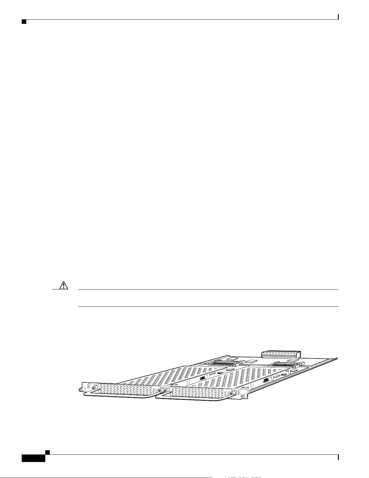
carrier card increases backplane capacity and allows OIR of the feature cards. (See Figure 2-1.)
Figure 2-1 Carrier Card with Two Feature Cards Installed
NP108
ACT
OK
MAINT
NP108
ACT
OK
MAINT
122109
2-2
Cisco AS5350XM and Cisco AS5400XM Universal Gateways Card Installation Guide
78-17406-01
Page 27
Chapter 2 Feature Card and Carrier Card Guidelines
Removing and Installing Populated Carrier Cards
Warning
Warning
Warning
Caution Before you remove a carrier card, see Chapter 1, “Safety Warnings, Recommendations, and Tools
Before working on a chassis or working near power supplies, unplug the power cord on AC units;
disconnect the power at the circuit breaker on DC units.
Before performing any of the following procedures, ensure that power is removed from the DC circuit.
Statement 1003
Before connecting or disconnecting ground or power wires to the chassis, ensure that power is
removed from the DC circuit. To ensure that all power is OFF, locate the circuit breaker on the panel
board that services the DC circuit, switch the circuit breaker to the OFF position, and tape the switch
handle of the circuit breaker in the OFF position.
Required.”
Removing a Populated Carrier Card
Warning
Before opening the unit, disconnect the telephone-network cables to avoid contact with
telephone-network voltages.
Statement 1041
Statement 12
Statement 140
Warning
Do not work on the system or connect or disconnect cables during periods of lightning activity.
Statement 1001
To remove a populated carrier card, follow the steps below:
Step 1 Power down the chassis.
Step 2 Disconnect all interface cables from the universal gateway, and secure them out of the way.
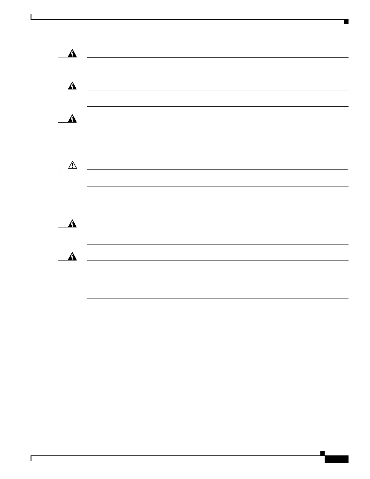
Step 3 Loosen the two captive screws that secure the carrier card to the chassis until each screw is free of the
chassis. (See Figure 2-2 and Figure 2-3.)
78-17406-01
Cisco AS5350XM and Cisco AS5400XM Universal Gateways Card Installation Guide
2-3
Page 28
Removing and Installing Populated Carrier Cards
Figure 2-2 Loosening the Captive Screws on the Cisco AS5350XM
Captive screw
Figure 2-3 Loosening the Captive Screws on the Cisco AS5400XM
DFC
Carrier card
Chapter 2 Feature Card and Carrier Card Guidelines
Chassis
36002
Captive screw
Chassis
37159
Captive
screw
DFC
Carrier
card
DFC
Captive
screw
Step 4 Grasp the feature card handles and gently pull them toward you to guide the carrier card out of the slot.
Place one hand under the carrier card as you pull it out of the chassis. (See Figure 2-4 and Figure 2-5.)
Note Use the feature card handles to remove the carrier card. Ensure that the feature cards are secured
to the carrier card.
Figure 2-4 Removing the Carrier Card from the Cisco AS5350XM
36003
2-4
Cisco AS5350XM and Cisco AS5400XM Universal Gateways Card Installation Guide
78-17406-01
Page 29
Chapter 2 Feature Card and Carrier Card Guidelines
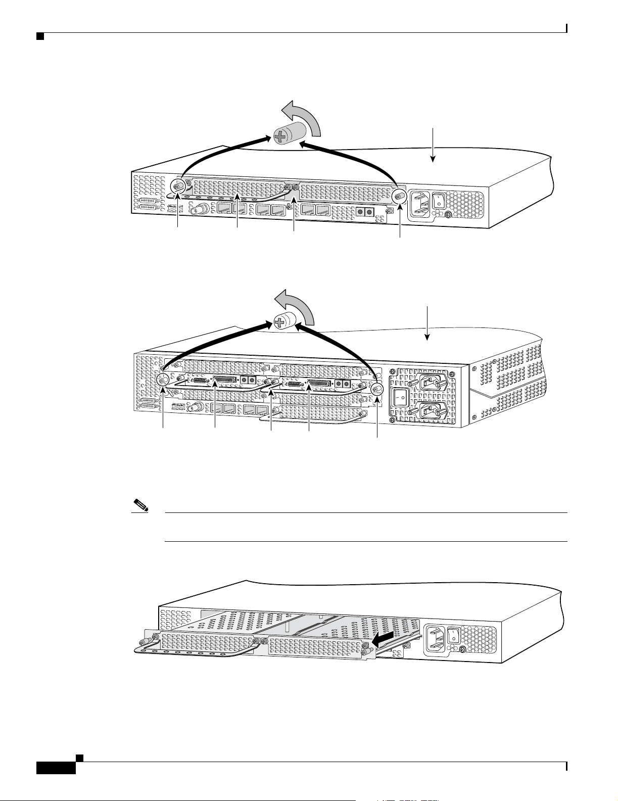
Figure 2-5 Removing the Carrier Card from the Cisco AS5400XM
Removing and Installing Populated Carrier Cards
37160
Step 5
Step 6 If the backplane slot is to remain empty, install a blank cover over the open slot to ensure proper airflow
After you remove the carrier card from the chassis, set it aside on an ESD-preventive mat.
inside the chassis. (See Figure 2-6.)
Figure 2-6 Blank Filler Panel
Installing a Populated Carrier Card
To install a populated carrier card:
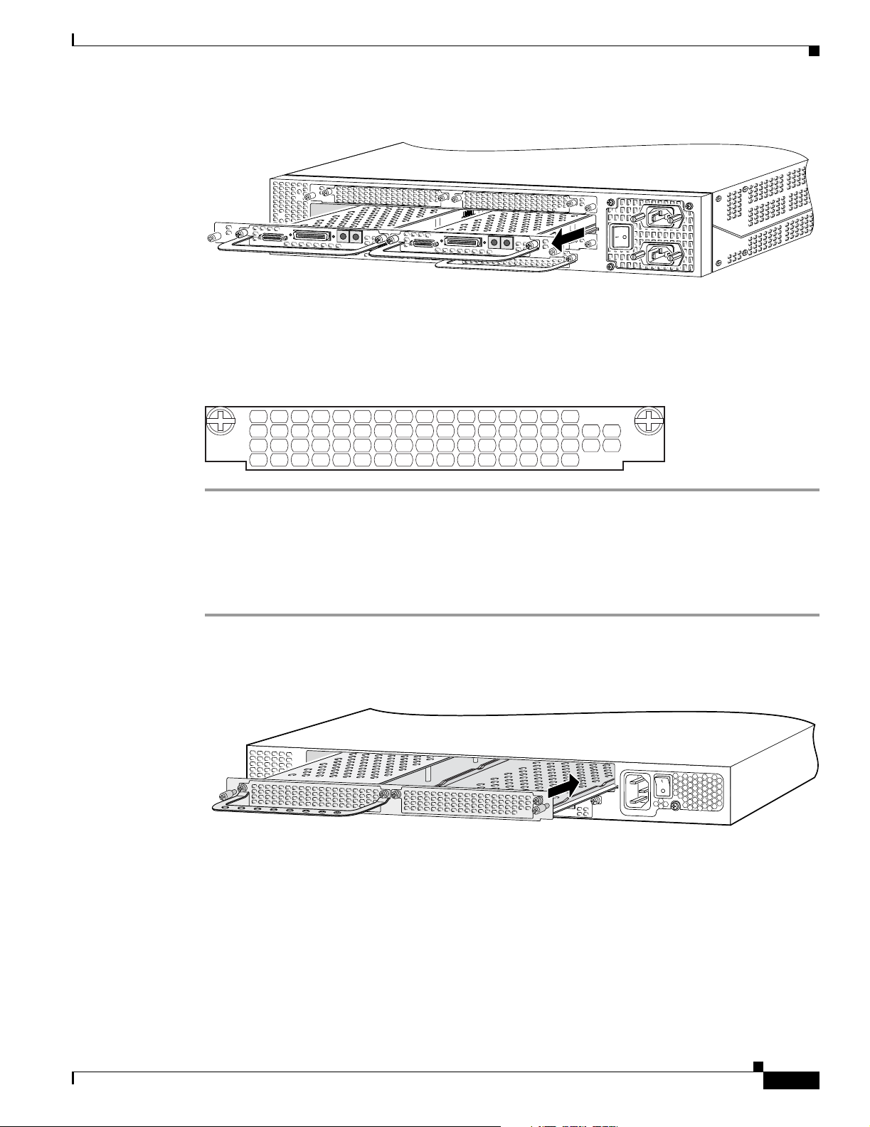
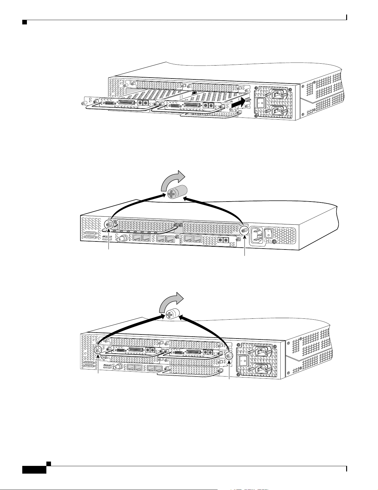
Step 1 Slide the carrier card into the slot until it touches the backplane connector. (See Figure 2-7 and
Figure 2-8.)
Figure 2-7 Installing the Carrier Card in the Cisco AS5350XM
36033
78-17406-01
36004
Cisco AS5350XM and Cisco AS5400XM Universal Gateways Card Installation Guide
2-5
Page 30
Removing and Installing Populated Carrier Cards
Figure 2-8 Installing the Carrier Card in the Cisco AS5400XM
Step 2 Align the captive screws with their holes, and seat the card completely.
Step 3 Tighten the two captive screws to secure the carrier card to the chassis. (See Figure 2-9 and Figure 2-10.)
Figure 2-9 Tightening the Captive Screws on the Cisco AS5350XM
Chapter 2 Feature Card and Carrier Card Guidelines
37161
Step 4
36005
Captive screw
Captive screw
Figure 2-10 Tightening the Captive Screws on the Cisco AS5400XM
Captive
screw
Captive
screw
37162
If the carrier card has a blank feature card slot, install a blank cover over the open feature card slot to
ensure proper airflow inside the chassis. (See Figure 2-11.)
2-6
Cisco AS5350XM and Cisco AS5400XM Universal Gateways Card Installation Guide
78-17406-01
Page 31

Chapter 2 Feature Card and Carrier Card Guidelines
Figure 2-11 Blank Feature Card Cover
Step 5 For AC-powered units, reconnect the AC power cord. For DC-powered units, remove the tape from the
circuit breaker switch handle, and reinstate power by moving the handle of the circuit breaker to the ON
position. For more information about the AC and DC power supplies, see the chassis installation guide
for your universal gateway.
Step 6 Reconnect all interface cables.
Getting Help
For information about technical support, onsite service, and exchange and repair services, see the
“Obtaining Technical Assistance” section on page xvi.
Getting Help
36033
Where to Go Next
The remaining chapters of this guide include information about installing and troubleshooting feature
cards and about building cables.
• Chapter 3, “T1 and E1 Feature Cards”
• Chapter 4, “Channelized T3 Feature Card”
• Chapter 5, “Universal Port and Dial-Only Feature Cards”
• Chapter 6, “Voice Feature Card”
• Chapter 7, “Troubleshooting”
• Appendix A, “Cabling Specifications”
78-17406-01
Cisco AS5350XM and Cisco AS5400XM Universal Gateways Card Installation Guide
2-7
Page 32

Where to Go Next
Chapter 2 Feature Card and Carrier Card Guidelines
2-8
Cisco AS5350XM and Cisco AS5400XM Universal Gateways Card Installation Guide
78-17406-01
Page 33

Overview
CHA P TER
3
T1 and E1 Feature Cards
This chapter provides procedures for installing and removing the T1 and E1 feature cards and includes
the following sections:
• Overview, page 3-1
• Online Installation and Removal of the T1 or E1 Feature Card, page 3-2
• Configuring Input Impedance for the E1 Feature Card, page 3-11
• Getting Help, page 3-12
• Where to Go Next, page 3-12
You can install a T1 or E1 feature card in any feature card slot of the universal gateway chassis. (See
Figure 3-1 through Figure 3-3.)
Figure 3-1 2-Port T1 or E1 Feature Card
Bantam ports
T1 or E1 ports
0
1
Figure 3-2 4-Port T1 or E1 Feature Card
Bantam ports
T1 or E1 ports
0
1
2
3
2 PRI
Rx
Tx
ACT
OK
4 PRI
Rx
ACT
OK/
Tx
MAINT
35840
56023
78-17406-01
Cisco AS5350XM and Cisco AS5400XM Universal Gateways Card Installation Guide
3-1
Page 34

Online Installation and Removal of the T1 or E1 Feature Card
Figure 3-3 8-Port T1 or E1 Feature Card
Note The Cisco AS5350XM and Cisco AS5400XM universal gateways each support only one type of
WAN feature card at a time. See Chapter 7, “Troubleshooting,” for more information.
Each T1 or E1 feature card provides physical line termination for multiple DS-0 channels and uses
onboard HDLC controllers to terminate digital (ISDN) calls. For network specifications, see Tab l e 3- 1
and Table 3-2. You can use the bantam jack ports on the feature card to monitor a line.
Chapter 3 T1 and E1 Feature Cards
29030
Table 3-1 T1 Feature Card Network Specifications
Description Specification
Line rate 1.544 Mbps
Data rate (per port) number x 56 or number x 64 kbps, where number = 1 to 24
Standards AT&T Pub. 62411, 54016, and 43081, and ANSI T1.403
Input impedance 100 ohm per port
Table 3-2 E1 Feature Card Network Specifications
Description Specification
Line rate 2.048 Mbps
Data rate (per port) number x 56 or number x 64 kbps, where number = 1 to 31.
Input impedance 75 or 120 ohm per port
Note The factory default setting for the E1 ports is 120 ohm. For
information about changing the impedance, see the “Configuring
Input Impedance for the E1 Feature Card” section on page 3-11.
Online Installation and Removal of the T1 or E1 Feature Card
3-2
To remove a feature card without dropping any calls or connections, you will need to take the feature
card out of service by using the busyout command to disable the feature card. The busyout command is
executed on a per–feature card basis and will disable the card after waiting for the active services to
terminate.
If there are active calls on the feature card after you execute the busyout command, wait for the calls to
drop. To view the status of the termination process, use the show busyout command.
Cisco AS5350XM and Cisco AS5400XM Universal Gateways Card Installation Guide
78-17406-01
Page 35

Chapter 3 T1 and E1 Feature Cards
Caution The online installation and removal (OIR) of new cards should be done only during times of low CPU
utilization, such as during maintenance.
Caution To avoid erroneous failure messages, remove or insert only one feature card at a time.
When you replace a feature card in a slot with a new feature card of the same type, the system software
recognizes the new feature card and brings up the trunk interfaces automatically.
If you replace the existing feature card with a new feature card of a different type, you must reconfigure
the system. For configuration details, see the Cisco AS5350XM and Cisco AS5400XM Universal
Gateways Software Configuration Guide.
Removing the T1 or E1 Feature Card
To remove the T1 or E1 feature card, follow these steps.
Online Installation and Removal of the T1 or E1 Feature Card
Note An example showing the output from each command is provided after the procedure. See the “Online
Insertion and Removal Example for the T1 or E1 Feature Card” section on page 3-6.
Step 1 Determine which slot the feature card is in (see Figure 3-4 and Figure 3-5) by entering the show chassis
slot command in privileged EXEC mode:
Router# show chassis slot
Note These commands are not valid for slot 0. Slot 0 is the motherboard.
Figure 3-4 Slot Numbering on the Cisco AS5350XM Chassis
36006
Slot 2
Slot 0
Slot 1
Slot 3
78-17406-01
Cisco AS5350XM and Cisco AS5400XM Universal Gateways Card Installation Guide
3-3
Page 36

Online Installation and Removal of the T1 or E1 Feature Card
Figure 3-5 Slot Numbering on the Cisco AS5400XM Chassis
Chapter 3 T1 and E1 Feature Cards
34977
Slot 2
Slot 4
Slot 6
Step 2
Step 3 Check busyout status for the slot, by entering the show busyout command.
Step 4 You can use the clear port command to immediately disable active calls on a universal port, dial-only,
Initialize the software busyout procedure by entering the busyout command:
Router# busyout slot-number
Router# show busyout slot-number
Slot 1Slot 0
Slot 3
Slot 5
Slot 7
or voice feature card. For more information on the universal port or dial-only feature card, see Chapter 5,
“Universal Port and Dial-Only Feature Cards.” For more information on the voice feature card, see
Chapter 6, “Voice Feature Card.” Use the show controller command to show the card that is associated
with the T1 or E1 feature card.
Router# show controller t1/e1 slot-number/control-number timeslot timeslot-number
Router# clear port slot-number/port number
Note The clear port command applies only to universal port, dial-only, or voice feature cards.
Step 5 Verify that the OK/MAINT LED is off; this indicates that the feature card is offline and ready to be
removed.
3-4
Note The OK/MAINT LED is green before you enter the busyout command. After you enter the
busyout command, the LED changes to yellow. The LED turns off after all calls are
disconnected and resources are taken out of service, indicating that busyout is complete.
Step 6 Attach an ESD-preventive wrist strap.
Warning
Do not work on the system or connect or disconnect cables during periods of lightning activity.
Statement 1001
Step 7 Disconnect all interface cables from the feature card and secure them out of the way.
Step 8 Loosen the two captive screws that secure the feature card to the chassis until each screw is free of the
chassis. (See Figure 3-6 and Figure 3-7.)
Cisco AS5350XM and Cisco AS5400XM Universal Gateways Card Installation Guide
78-17406-01
Page 37

Chapter 3 T1 and E1 Feature Cards
Figure 3-6 Loosening the Captive Screws on the Cisco AS5350XM Universal Gateway
Online Installation and Removal of the T1 or E1 Feature Card
Chassis
Rx
Tx
ACT
Captive
screw
2 PRI
OK
Carrier
Captive
screw
0
1
DFC
card
Figure 3-7 Loosening the Captive Screws on the Cisco AS5400XM Universal Gateway
Captive
screw
Captive
screw
36814
37163
78-17406-01
Step 9
Grasp the feature card handle with one hand. Pull the card toward you until the card slides free of the
chassis. Grasp the ventilated metal cover with your other hand to support and guide the feature card out
of the slot. (See Figure 3-8 and Figure 3-9.)
Caution Avoid touching any pins or circuit board components when you remove or install a feature card.
Figure 3-8 Removing the Feature Card from the Cisco AS5350XM Universal Gateway
0
1
2 PRI
Rx
Tx
ACT
OK
Cisco AS5350XM and Cisco AS5400XM Universal Gateways Card Installation Guide
36815
3-5
Page 38

Online Installation and Removal of the T1 or E1 Feature Card
Figure 3-9 Removing the Feature Card from the Cisco AS5400XM Universal Gateway
Step 10 After you remove the feature card from the chassis, set it aside on an ESD-preventive mat.
Step 11 If the feature card slot is to remain empty, install a blank cover over the open feature card slot to ensure
proper airflow inside the chassis. (See Figure 3-10.)
Figure 3-10 Blank Feature Card Cover
Chapter 3 T1 and E1 Feature Cards
37164
Online Insertion and Removal Example for the T1 or E1 Feature Card
The following output is an example of the online insertion and removal (OIR) process for an E1 feature
card in slot 6 of the universal gateway:
Router# show chassis slot 6
Slot 6:
DFC type is E1 8 PRI DFC
OIR events:
Number of insertions = 0, Number of removals = 0
DFC State is DFC_S_OPERATIONAL
Router#
Router# busyout 6
Busyout in progress for 6
Router# show busyout 6
Busyout status for trunk DFC slot = 6:
DFC slot busyout is in progress
(p - pending, s - static(cfg/exec), d - dynamic, n - none)
6/0 :s s p p p p p p p p p p p p p n p p p p p p p p p p p p p p p
6/1 :s s s p p p p p p p p p p p p n p p p p p p p p p p p p p p p
6/2 :s s s p p p p p p p p p p p p n p p p p p p p p p p p p p p p
6/3 :s s s s p p p p p p p p p p p n p p p p p p p p p p p p p p p
6/4 :s s s p p p p p p p p p p p p n p p p p p p p p p p p p p p p
6/5 :s s s p p p p p p p p p p p p n p p p p p p p p p p p p p p p
6/6 :s s s p p p p p p p p p p p p n p p p p p p p p p p p p p p p
6/7 :s s p p p p p p p p p p p p p n p p p p p p p p p p p p p p p
36033
3-6
Router#
Router# show controller e1 6/0 timeslot 1-31
Cisco AS5350XM and Cisco AS5400XM Universal Gateways Card Installation Guide
78-17406-01
Page 39

Chapter 3 T1 and E1 Feature Cards
E1 6/0 is up:
DS0 Type Modem Status rxA rxB rxC rxD txA txB txC txD
1 pri - idle
2 pri - idle
3 pri-modem 1/70 active
4 pri-modem 1/46 active
5 pri-modem 1/22 active
6 pri-modem 4/61 active
7 pri-modem 4/53 active
8 pri-modem 4/45 active
9 pri-modem 4/37 active
10 pri-modem 4/29 active
11 pri-modem 4/21 active
12 pri-modem 4/13 active
13 pri-modem 4/05 active
14 pri-modem 2/105 active
15 pri-modem 2/97 active
16 pri-D channel - 17 pri-modem 2/89 active
18 pri-modem 2/81 active
19 pri-modem 2/73 active
20 pri-modem 2/65 active
21 pri-modem 2/57 active
22 pri-modem 2/49 active
23 pri-modem 2/41 active
24 pri-modem 2/33 active
25 pri-modem 2/25 active
26 pri-modem 2/17 active
27 pri-modem 2/09 active
28 pri-modem 2/01 active
29 pri-modem 1/107 active
30 pri-modem 1/99 active
31 pri-modem 1/91 active
Router#
Router# show busyout 6
Busyout status for trunk DFC slot = 6:
DFC slot busyout is in progress
(p - pending, s - static(cfg/exec), d - dynamic, n - none)
Online Installation and Removal of the T1 or E1 Feature Card
78-17406-01
6/0 :s s p p p p p p p p p p p p p n p p p p p p p p p p p p p p p
6/1 :s s s p p p p p p p p p p p p n p p p p p p p p p p p p p p p
6/2 :s s s p p p p p p p p p p p p n p p p p p p p p p p p p p p p
6/3 :s s s s p p p p p p p p p p p n p p p p p p p p p p p p p p p
6/4 :s s s p p p p p p p p p p p p n p p p p p p p p p p p p p p p
6/5 :s s s p p p p p p p p p p p p n p p p p p p p p p p p p p p p
6/6 :s s s p p p p p p p p p p p p n p p p p p p p p p p p p p p p
6/7 :s s p p p p p p p p p p p p p n p p p p p p p p p p p p p p p
Router# clear port 1/70
This will clear port 1/70[confirm]
*Jan 1 00:27:37.083:%PORT-6-SM_PORT_CLEARED:Port 1/70 Cleared
Router# show busyout 6
Busyout status for trunk DFC slot = 6:
DFC slot busyout is in progress
(p - pending, s - static(cfg/exec), d - dynamic, n - none)
6/0 :s s s s s s s s s s p p p p p n p p p p p p p p p p p p p p p
6/1 :s s s p p p p p p p p p p p p n p p p p p p p p p p p p p p p
6/2 :s s s p p p p p p p p p p p p n p p p p p p p p p p p p p p p
6/3 :s s s s p p p p p p p p p p p n p p p p p p p p p p p p p p p
6/4 :s s s p p p p p p p p p p p p n p p p p p p p p p p p p p p p
Cisco AS5350XM and Cisco AS5400XM Universal Gateways Card Installation Guide
3-7
Page 40

Online Installation and Removal of the T1 or E1 Feature Card
6/5 :s s s p p p p p p p p p p p p n p p p p p p p p p p p p p p p
6/6 :s s s p p p p p p p p p p p p n p p p p p p p p p p p p p p p
6/7 :s s p p p p p p p p p p p p p n p p p p p p p p p p p p p p p
Router#
Router#
*Jan 1 00:32:40.271:%PORT-6-SM_PORT_CLEARED:All Ports Are Cleared
*Jan 1 00:32:40.635:%OIR-6-REMCARD:Card removed from slot 6, interfaces disabled
*Jan 1 00:32:40.643:%TRUNK_CLOCK-6-SWITCH:Switching to the clock on slot 7 port 0
priority 214 as the current primary has gone bad
*Jan 1 00:32:40.647:%CSM-5-PRI:delete PRI at slot 6, unit 0, channel 15 with index 0
*Jan 1 00:32:40.655:%CSM-5-PRI:delete PRI at slot 6, unit 1, channel 15 with index 1
*Jan 1 00:32:40.663:%CSM-5-PRI:delete PRI at slot 6, unit 2, channel 15 with index 2
*Jan 1 00:32:40.667:%CSM-5-PRI:delete PRI at slot 6, unit 3, channel 15 with index 3
*Jan 1 00:32:40.675:%CSM-5-PRI:delete PRI at slot 6, unit 4, channel 15 with index 4
*Jan 1 00:32:40.683:%CSM-5-PRI:delete PRI at slot 6, unit 5, channel 15 with index 4
*Jan 1 00:32:40.687:%CSM-5-PRI:delete PRI at slot 6, unit 6, channel 15 with index 3
*Jan 1 00:32:40.695:%CSM-5-PRI:delete PRI at slot 6, unit 7, channel 15 with index 2
Router#
*Jan 1 00:32:48.515:%ISDN-6-LAYER2DOWN:Layer 2 for Interface Se6/4:15, TEI 0 changed to
down
*Jan 1 00:32:48.523:%ISDN-6-LAYER2DOWN:Layer 2 for Interface Se6/5:15, TEI 0 changed to
down
*Jan 1 00:32:48.523:%ISDN-6-LAYER2DOWN:Layer 2 for Interface Se6/0:15, TEI 0 changed to
down
*Jan 1 00:32:48.523:%ISDN-6-LAYER2DOWN:Layer 2 for Interface Se6/3:15, TEI 0 changed to
down
*Jan 1 00:32:48.523:%ISDN-6-LAYER2DOWN:Layer 2 for Interface Se6/6:15, TEI 0 changed to
down
*Jan 1 00:32:48.527:%ISDN-6-LAYER2DOWN:Layer 2 for Interface Se6/7:15, TEI 0 changed to
down
*Jan 1 00:32:48.527:%ISDN-6-LAYER2DOWN:Layer 2 for Interface Se6/1:15, TEI 0 changed to
down
Router#
Router# show chassis slot 6
Chapter 3 T1 and E1 Feature Cards
Slot 6:
DFC type is Empty DFC
DFC is not powered
OIR events:
Number of insertions = 0, Number of removals = 1
Router#
Router# show chassis slot 6
Slot 6:
DFC type is E1 8 PRI DFC
OIR events:
Number of insertions = 1, Number of removals = 1
DFC State is DFC_S_OPERATIONAL
3-8
Cisco AS5350XM and Cisco AS5400XM Universal Gateways Card Installation Guide
78-17406-01
Page 41

Chapter 3 T1 and E1 Feature Cards
Installing the T1 or E1 Feature Card
Online Installation and Removal of the T1 or E1 Feature Card
Warning
Do not work on the system or connect or disconnect cables during periods of lightning activity.
Statement 1001
Warning
The E1 interface card may only be installed in an ACA-permitted customer equipment or a Data
Terminal Equipment (DTE) that is exempted from ACA’s permit requirements. The customer equipment
must only be housed in a cabinet that has screw-down lids to stop user access to overvoltages on the
customer equipment. The customer equipment has circuitry that may have telecommunications
Warning
network voltages on them.
The telecommunications lines must be disconnected 1) before unplugging the main power connector
and/or 2) while the housing is open.
Statement 90
Statement 89
Note When you replace a feature card in a slot with a new feature card of the same type, the system software
recognizes the new feature card and brings up the trunk interfaces automatically. If you replace the
existing feature card with a new feature card of a different type, you must reconfigure the system. For
configuration details, see the Cisco AS5350XM and Cisco AS5400XM Universal Gateways Software
Configuration Guide.
To install the T1 or E1 feature card, follow these steps:
Step 1 Attach an ESD-preventive wrist strap.
Step 2 Slide the feature card into the slot until the connector pins make contact with the carrier card backplane
connector. (See Figure 3-11 and Figure 3-12.)
Figure 3-11 Installing the T1 or E1 Feature Card in the Cisco AS5350XM Universal Gateway
0
1
2 PRI
Rx
Tx
ACT
OK
36816
78-17406-01
Cisco AS5350XM and Cisco AS5400XM Universal Gateways Card Installation Guide
3-9
Page 42

Online Installation and Removal of the T1 or E1 Feature Card
Figure 3-12 Installing the T1 or E1 Feature Card in the Cisco AS5400XM Universal Gateway
Chapter 3 T1 and E1 Feature Cards
37165
Step 3
Align the captive screws with their holes, and seat the card completely.
Step 4 Tighten the screws to secure the feature card to the chassis. (See Figure 3-13 and Figure 3-14.)
Figure 3-13 Tightening the Captive Screws on the Cisco AS5350XM Universal Gateway
Chassis
Rx
Tx
ACT
Captive
screw
2 PRI
OK
Carrier
Captive
screw
0
1
DFC
card
Figure 3-14 Tightening the Captive Screws on the Cisco AS5400XM Universal Gateway
36817
3-10
Step 5
Captive
screw
Check the card LEDs to verify that the card is working properly. For information about feature card
Captive
screw
LEDs, see Chapter 7, “Troubleshooting.”
Cisco AS5350XM and Cisco AS5400XM Universal Gateways Card Installation Guide
37163
78-17406-01
Page 43

Chapter 3 T1 and E1 Feature Cards
Configuring Input Impedance for the E1 Feature Card
Note For information about configuring the T1 or E1 ports, see the Cisco AS5350XM and Cisco AS5400XM
Universal Gateways Software Configuration Guide.
Configuring Input Impedance for the E1 Feature Card
You can set the input impedance of the E1 feature card before or after running the setup script. For
information on configuring the universal gateway with the setup script, see the Cisco AS5350XM and
Cisco AS5400XM Universal Gateways Software Configuration Guide.
Configuration
To set the input impedance for the E1 feature card, use the line-termination command.
Command Purpose
Step 1
Step 2
Step 3
Step 4
Step 5
Router> enable
Password: password
Router#
Router# configure terminal
Enter configuration commands, one per line. End
with CNTL/Z.
Router(config)#
Router(config)# controller e1 0
Router(config-controller)#
Router(config-controller)# line-termination
75-ohm
Router(config-controller)# Ctrl-Z
Router#
%SYS-5-CONFIG_I: Configured from console by
console
Enters enable mode.
Enter the password. You have entered enable mode when
the prompt changes to
Router#.
Enters global configuration mode. You have entered
global configuration mode when the prompt changes to
Router(config)#.
Enter the controller number on which you are configuring
input impedance.
Sets the input impedance to 75 ohm for the controller.
The factory-set default is 120 ohm. Repeat Step 3 and
Step 4 for the other controllers.
Returns to enable mode.
This message is normal and does not indicate an error.
78-17406-01
Cisco AS5350XM and Cisco AS5400XM Universal Gateways Card Installation Guide
3-11
Page 44

Getting Help
Verification
Note By default, input impedance is 120 ohm. In the following example, the input impedance was successfully
Chapter 3 T1 and E1 Feature Cards
To verify the impedance, enter the show running-config command.
changed to 75 ohm using the line-termination 75-ohm command. Some of the configuration has been
deleted for readability.
Router# show running-config
Building configuration...
Current configuration:
.
.
.
!
controller E1 0
clock source free-running
line-termination 75-ohm
pri-group timeslots 1-31
!
.
.
.
Router#
Getting Help
For information about technical support, onsite service, and exchange and repair services, see the
“Obtaining Technical Assistance” section on page xvi.
Where to Go Next
The remaining chapters of this guide include information about installing and troubleshooting feature
cards and about building cables.
• Chapter 4, “Channelized T3 Feature Card”
• Chapter 5, “Universal Port and Dial-Only Feature Cards”
• Chapter 6, “Voice Feature Card”
• Chapter 7, “Troubleshooting”
• Appendix A, “Cabling Specifications”
3-12
Cisco AS5350XM and Cisco AS5400XM Universal Gateways Card Installation Guide
78-17406-01
Page 45

Overview
CHA P TER
4
Channelized T3 Feature Card
This chapter describes the channelized T3 (CT3) feature card and includes the following sections:
• Overview, page 4-1
• Online Insertion and Removal of the CT3 Feature Card, page 4-2
• Getting Help, page 4-7
• Where to Go Next, page 4-7
The CT3 feature card provides physical line termination for a channelized T3 ingress trunk line. It uses
an onboard multiplexer to multiplex 28 channelized T1 lines into a single channelized T3 line. (See
Figure 4-1.)
Figure 4-1 CT3 Feature Card
29029
Note The Cisco AS5350XM and Cisco AS5400XM universal gateways each support only one type of
WAN feature card at a time. See Chapter 7, “Troubleshooting,” for more information.
The CT3 feature card provides physical line termination for up to 672 DS0 channels and uses onboard
High-Level Data Link Control (HDLC) controllers to terminate digital (ISDN) calls.
You can use the bantam jack ports on the feature card to monitor a T1 line or to test any of the individual
T1 channels in drop and insert mode.
You can install a CT3 feature card in any feature card slot in a universal gateway chassis.
78-17406-01
Cisco AS5350XM and Cisco AS5400XM Universal Gateways Card Installation Guide
4-1
Page 46

Chapter 4 Channelized T3 Feature Card
Online Insertion and Removal of the CT3 Feature Card
Online Insertion and Removal of the CT3 Feature Card
To remove a feature card without dropping any calls or connections, you will need to take the feature
card out of service by using the busyout command to disable the feature card. The busyout command is
executed on a per–feature card basis and will disable the card after waiting for the active services to
terminate.
If there are active calls on the feature card after you execute the busyout command, wait for the calls to
drop. To view the status of the termination process, use the show busyout command.
Caution The online installation and removal (OIR) of new cards should be done only during times of low CPU
utilization, such as during maintenance.
Caution To avoid erroneous failure messages, remove or insert only one feature card at a time.
When you replace a feature card in a slot with a new feature card of the same type, the system software
recognizes the new feature card and brings up the trunk interfaces automatically.
If you replace the existing feature card with a new feature card of a different type, you must reconfigure
the system. For configuration details, see the Cisco AS5350XM and Cisco AS5400XM Universal
Gateways Software Configuration Guide.
Removing the CT3 Feature Card
To remove the CT3 feature card, follow these steps.
Note The OIR procedure for the CT3 feature card is similar to that for the T1 or E1 feature card. See the
“Online Insertion and Removal Example for the T1 or E1 Feature Card” section on page 3-6 for an
example of the output during OIR of an E1 feature card.
Step 1 Determine which slot the feature card is in (see Figure 4-2 and Figure 4-3) by entering the show chassis
slot command in privileged EXEC mode:
Router# show chassis slot
Note These commands are not valid for slot 0. Slot 0 is the motherboard.
Figure 4-2 Slot Numbering on the Cisco AS5350XM Chassis
Slot 0
Slot 2
Slot 1
Slot 3
36006
4-2
Cisco AS5350XM and Cisco AS5400XM Universal Gateways Card Installation Guide
78-17406-01
Page 47

Chapter 4 Channelized T3 Feature Card
Figure 4-3 Slot Numbering on the Cisco AS5400XM Chassis
Online Insertion and Removal of the CT3 Feature Card
34977
Slot 2
Slot 4
Slot 6
Step 2
Step 3 Check busyout status for the slot, by entering the show busyout command.
Step 4 You can use the clear port command to immediately disable active calls on the universal port, dial-only,
Initialize the software busyout procedure by entering the busyout command:
Router# busyout slot-number
Router# show busyout slot-number
Slot 1Slot 0
Slot 3
Slot 5
Slot 7
or voice feature card. For more information on the universal port or dial-only feature card, see Chapter 5,
“Universal Port and Dial-Only Feature Cards.” For more information on the voice feature card, see
Chapter 6, “Voice Feature Card.” Use the show controller command to show the feature card that is
associated with the CT3 feature card.
Router# show controller t3 slot-number/control-number timeslot timeslot-number
Router# clear port slot-number/port number
Note The clear port command applies only to universal port, dial-only, or voice feature cards.
Step 5 Verify that the OK/MAINT LED is off; this indicates that the feature card is offline and ready to be
removed.
78-17406-01
Note The OK/MAINT LED is green before you enter the busyout command. After you enter the
busyout command, the LED changes to yellow. The LED turns off after all calls are
disconnected and resources are taken out of service, indicating that busyout is complete.
Step 6 Attach an ESD-preventive wrist strap.
Warning
Do not work on the system or connect or disconnect cables during periods of lightning activity.
Statement 1001
Step 7 Disconnect all interface cables from the feature card and secure them out of the way.
Cisco AS5350XM and Cisco AS5400XM Universal Gateways Card Installation Guide
4-3
Page 48

Online Insertion and Removal of the CT3 Feature Card
Note The OIR procedure for the CT3 feature card is similar to that for the T1 or E1 feature card. See
the “Online Insertion and Removal Example for the T1 or E1 Feature Card” section on page 3-6
for an example of the output during OIR of an E1 feature card.
Step 8 Loosen the two captive screws that secure the feature card to the chassis until each screw is free of the
chassis. (See Figure 4-4 and Figure 4-5.)
Figure 4-4 Loosening the Captive Screws on the Cisco AS5350XM Universal Gateway
Chapter 4 Channelized T3 Feature Card
Chassis
Step 9
58760
Captive
screw
DFC
Captive
screw
Carrier
card
Figure 4-5 Loosening the Captive Screws on the Cisco AS5400XM Universal Gateway
Captive
screw
Captive
screw
37167
Grasp the feature card handle with one hand. Pull the card toward you until the card slides free of the
chassis. Grasp the ventilated metal cover with your other hand to support and guide the feature card out
of the slot. (See Figure 4-6 and Figure 4-7.)
4-4
Caution Avoid touching any pins or circuit board components when you remove or install a feature card.
Cisco AS5350XM and Cisco AS5400XM Universal Gateways Card Installation Guide
78-17406-01
Page 49

Chapter 4 Channelized T3 Feature Card
Figure 4-6 Removing the Feature Card from the Cisco AS5350XM Universal Gateway
Figure 4-7 Removing the Feature Card from the Cisco AS5400XM Universal Gateway
Online Insertion and Removal of the CT3 Feature Card
58761
Step 10
Step 11 If a feature card slot on the carrier card is to remain empty, install a blank cover over the open feature
After you remove the feature card from the chassis, set it aside on an ESD-preventive mat.
card slot to ensure proper airflow inside the chassis. (See Figure 4-8.)
Figure 4-8 Blank Feature Card Cover
Installing the CT3 Feature Card
Warning
Do not work on the system or connect or disconnect cables during periods of lightning activity.
Statement 1001
37168
36033
78-17406-01
Note When you replace a feature card with a new feature card of the same type in the same slot, the system
software recognizes the new feature card and brings up the trunk interfaces automatically. If you replace
the existing feature card with a new feature card of a different type, you must reconfigure the system.
For configuration details, see the Cisco AS5350XM and Cisco AS5400XM Universal Gateways Software
Configuration Guide.
Cisco AS5350XM and Cisco AS5400XM Universal Gateways Card Installation Guide
4-5
Page 50

Online Insertion and Removal of the CT3 Feature Card
To install the CT3 feature card, follow these steps:
Step 1 Attach an ESD-preventive wrist strap.
Step 2 Slide the feature card into the slot until the connector pins make contact with the carrier card backplane
connector. (See Figure 4-9 and Figure 4-10.)
Figure 4-9 Installing the CT3 Feature Card in the Cisco AS5350XM Universal Gateway
Figure 4-10 Installing the CT3 Feature Card in the Cisco AS5400XM Universal Gateway
Chapter 4 Channelized T3 Feature Card
58762
Step 3
Align the captive screws with their holes, and seat the card completely.
Step 4 Tighten the screws to secure the feature card to the chassis. (See Figure 4-11 and Figure 4-12.)
Figure 4-11 Tightening the Captive Screws on the Cisco AS5350XM Universal Gateway
Chassis
Captive
Captive
screw
DFC
screw
Carrier
card
37169
58763
4-6
Cisco AS5350XM and Cisco AS5400XM Universal Gateways Card Installation Guide
78-17406-01
Page 51

Chapter 4 Channelized T3 Feature Card
Figure 4-12 Tightening the Captive Screws on the Cisco AS5400XM Universal Gateway
Getting Help
Captive
screw
Step 5
Check the card LEDs to verify that the card is working properly. For information about feature card
LEDs, see Chapter 7, “Troubleshooting.”
Getting Help
For information about technical support, onsite service, and exchange and repair services, see the
“Obtaining Technical Assistance” section on page xvi.
Where to Go Next
The remaining chapters of this guide include information about installing and troubleshooting feature
cards and about building cables.
• Chapter 5, “Universal Port and Dial-Only Feature Cards”
• Chapter 6, “Voice Feature Card”
• Chapter 7, “Troubleshooting”
• Appendix A, “Cabling Specifications”
37170
Captive
screw
78-17406-01
Cisco AS5350XM and Cisco AS5400XM Universal Gateways Card Installation Guide
4-7
Page 52

Where to Go Next
Chapter 4 Channelized T3 Feature Card
4-8
Cisco AS5350XM and Cisco AS5400XM Universal Gateways Card Installation Guide
78-17406-01
Page 53

Overview
CHA P TER
5
Universal Port and Dial-Only Feature Cards
This chapter describes universal port and dial-only feature cards and includes the following sections:
• Overview, page 5-1
• Online Insertion and Removal of the Universal Port or Dial-Only Feature Card, page 5-3
• System Processing Engine Firmware, page 5-10
• Getting Help, page 5-10
• Where to Go Next, page 5-10
Two different types of Nextport digital signal processor (DSP) feature cards are available for
Cisco AS5350XM and Cisco AS5400XM universal gateways. (See Figure 5-1.)
• Universal port feature card—The universal port feature card supports 60 (NP-60) to 108 (NP-108)
voice, fax, and dial calls in Cisco AS5350XM and Cisco AS5400XM universal gateways.
• Dial-only feature card—The dial-only feature card supports 60 (DL-60) to 108 (DL-108) dial calls
in Cisco AS5350XM and Cisco AS5400XM universal gateways. It does not support voice or fax
services.
78-17406-01
Note Dial services include modem calls (all modulations), ISDN digital calls, V.110 data calls, and V.120 data
calls. Modem pass-through calls are not included in dial services.
For configuration details, see the Cisco AS5350XM and Cisco AS5400XM Universal Gateways Software
Configuration Guide. For information on voice and fax commands, see the Cisco IOS Voice
Configuration Library for your Cisco IOS software release at Cisco.com.
You can install a universal port or dial-only feature card in any card slot in the universal gateway chassis.
The universal port and dial-only feature cards do not require external connections.
Note The dial-only feature card is configured in the same way as the universal port feature card. This allows
the dial-only feature card to be used with your existing software configuration.
Cisco AS5350XM and Cisco AS5400XM Universal Gateways Card Installation Guide
5-1
Page 54

Chapter 5 Universal Port and Dial-Only Feature Cards
Overview
Figure 5-1 Universal Port or Dial-Only Feature Card
Note The versions of the universal port and dial-only feature cards are identified on the card faceplate. The
universal port feature card faceplates are labeled NP-60 or NP-108, depending on the number of calls
supported. The dial-only feature card faceplates are labeled DL-60 or DL-108, depending on the number
of calls supported.
Restrictions for the Universal Port and Dial-Only Feature Cards
31634
If a dial-only feature card is installed in a chassis with the universal port feature card, only the dial
services are supported. Tab l e 5-1 describes the behavior of the Cisco AS5350XM and Cisco AS5400XM
universal gateways with dial-only feature cards, universal port feature cards, or both types of cards
installed in the chassis.
Caution We do not recommend deploying dial-only feature cards in a chassis that supports voice and fax services,
because voice or fax calls assigned to the dial-only feature card will fail.
Note For information about mixing voice feature cards with the universal port and dial-only feature cards, see
the “Restrictions for the Voice Feature Card” section on page 6-2.
Table 5-1 Features Supported on Universal Port and Dial-Only Feature Cards
Feature Cards Installed Services Supported
Only dial-only feature cards installed Dial services
Only universal port feature cards installed Dial, voice, and fax services
Both universal port and dial-only feature cards
Dial services
installed
5-2
Cisco AS5350XM and Cisco AS5400XM Universal Gateways Card Installation Guide
78-17406-01
Page 55

Chapter 5 Universal Port and Dial-Only Feature Cards
Online Insertion and Removal of the Universal Port or Dial-Only Feature Card
Online Insertion and Removal of the Universal Port or Dial-Only
Feature Card
To remove a feature card without dropping any calls or connections, you will need to take the feature
card out of service by using the busyout command to disable the feature card. The busyout command is
executed on a per–feature card basis and will disable the card after waiting for the active services to
terminate.
If there are active calls on the feature card after you execute the busyout command, wait for the calls to
drop. To view the status of the termination process, use the show busyout command.
Caution The online installation and removal (OIR) of new cards should be done only during times of low CPU
utilization, such as during maintenance.
Caution To avoid erroneous failure messages, remove or insert only one feature card at a time.
When you replace a feature card in a slot with a new feature card of the same type, the system software
recognizes the new feature card and brings up the trunk interfaces automatically.
If you replace the existing feature card with a new feature card of a different type, you must reconfigure
the system. For configuration details, see the Cisco AS5350XM and Cisco AS5400XM Universal
Gateways Software Configuration Guide. For information on voice and fax commands, see the
Monitoring Voice and Fax Services on the Cisco AS5350 and Cisco AS5400 Universal Gateways online
document.
Removing the Universal Port or Dial-Only Feature Card
To remove the universal port or dial-only feature card, follow these steps.
Note An example showing the output from each command is provided after the procedure. See the “Online
Insertion and Removal Example for the Universal Port or Dial-Only Feature Card” section on page 5-6.
Step 1 Determine which slot the feature card is in (see Figure 5-2 and Figure 5-3) by entering the show chassis
slot command in privileged EXEC mode:
Router# show chassis slot
Note These commands are not valid for slot 0. Slot 0 is the motherboard.
78-17406-01
Cisco AS5350XM and Cisco AS5400XM Universal Gateways Card Installation Guide
5-3
Page 56

Online Insertion and Removal of the Universal Port or Dial-Only Feature Card
Figure 5-2 Slot Numbering on the Cisco AS5350XM Chassis
Chapter 5 Universal Port and Dial-Only Feature Cards
Slot 2
Slot 0
Slot 1
Slot 3
Figure 5-3 Slot Numbering on the Cisco AS5400XM Chassis
Slot 1Slot 0
Step 2
Slot 2
Slot 4
Slot 6
Initialize the software busyout procedure by entering the busyout command:
Router# busyout slot-number
Slot 3
Slot 5
Slot 7
Step 3 To check busyout status for the slot, enter the show busyout command:
Router# show busyout slot-number
36006
34977
5-4
Step 4 You can use the clear port command to immediately disable active calls on a universal port or dial-only
feature card.
Router# clear port slot-number/port number
Step 5 Verify that the OK/MAINT LED is off; this indicates that the feature card is offline and ready to be
removed.
Note The OK/MAINT LED is green before you enter the busyout command. After you enter the
busyout command, the LED changes to yellow. The LED turns off after all calls are
disconnected and resources taken out of service, indicating that busyout is complete.
Step 6 Attach an ESD-preventive wrist strap.
Warning
Do not work on the system or connect or disconnect cables during periods of lightning activity.
Statement 1001
Step 7 Loosen the two captive screws that secure the feature card to the chassis until each screw is free of the
chassis. (See Figure 5-4 and Figure 5-5.)
Cisco AS5350XM and Cisco AS5400XM Universal Gateways Card Installation Guide
78-17406-01
Page 57

Chapter 5 Universal Port and Dial-Only Feature Cards
Figure 5-4 Loosening the Captive Screws on the Cisco AS5350XM Universal Gateway
Online Insertion and Removal of the Universal Port or Dial-Only Feature Card
Chassis
36821
Captive
screw
DFC
Carrier card
Captive
screw
Figure 5-5 Loosening the Captive Screws on the Cisco AS5400XM Universal Gateway
Captive
screw
Captive
screw
37171
Step 8 Grasp the feature card handle with one hand. Pull the card toward you until the card slides free of the
chassis. Grasp the ventilated metal cover with your other hand to support and guide the feature card out
of the slot. (See Figure 5-6 and Figure 5-7.)
78-17406-01
Figure 5-6 Removing the Feature Card from the Cisco AS5350XM Universal Gateway
36819
Cisco AS5350XM and Cisco AS5400XM Universal Gateways Card Installation Guide
5-5
Page 58

Online Insertion and Removal of the Universal Port or Dial-Only Feature Card
Figure 5-7 Removing the Feature Card from the Cisco AS5400XM Universal Gateway
Caution Avoid touching any pins or circuit board components when you remove or install a feature card.
Step 9 After you remove the feature card, set it aside on an ESD-preventive mat.
Step 10 If the feature card slot is to remain empty, install a blank cover over the open feature card slot to ensure
proper airflow inside the chassis. (See Figure 5-8.)
Chapter 5 Universal Port and Dial-Only Feature Cards
37172
Figure 5-8 Blank Feature Card Cover
36033
Online Insertion and Removal Example for the Universal Port or Dial-Only Feature Card
The following output is an example of the online insertion and removal (OIR) process for a universal
port feature card in slot 3 of the universal gateway:
Router# show chassis slot 3
Slot 3:
DFC type is NP108 DFC
OIR events:
Number of insertions = 0, Number of removals = 0
DFC State is DFC_S_OPERATIONAL
Router#
Router# show busyout 3
Slot 3 is not being busied out
Router#
Router# busyout 3
Busyout in progress for 3
Router#
Router# show busyout 3
Slot busyout is in progress
Slot 3:Pending (64 calls remaining)
Router#
Router# show chassis slot 3
5-6
Slot 3:
DFC type is NP108 DFC
Cisco AS5350XM and Cisco AS5400XM Universal Gateways Card Installation Guide
78-17406-01
Page 59

Chapter 5 Universal Port and Dial-Only Feature Cards
OIR events:
Number of insertions = 0, Number of removals = 0
DFC State is DFC_S_OPERATIONAL
Router#
Router# clear port 3
This will clear ports 3/00 - 3/107[confirm]
Router#
*Jan 1 00:14:22.555:%PORT-6-SM_PORT_CLEARED:Port 3/00 - 3/107 Cleared
Router# show busyout 3
Slot busyout is in progress
Slot 3:Pending (54 calls remaining)
Router#
Router# show busyout 3
Slot busyout is in progress
Slot 3:Pending (36 calls remaining)
Router# show busyout 3
Slot busyout is in progress
Slot 3:Pending (30 calls remaining)
Router# clear port 3
This will clear ports 3/00 - 3/107[confirm]
Online Insertion and Removal of the Universal Port or Dial-Only Feature Card
Router#
*JRouteran 1 00:14:59.275:%PORT-6-SM_PORT_CLEARED:Port 3/00 - 3/107 Cleared
Router# show busyout 3
Slot busyout is in progress
Slot 3:Pending (9 calls remaining)
Router# clear port 3
*Jan 1 00:15:10.355:%NP_MD-6-MODULE_DOWN:NextPort module 3/0/0 down
*Jan 1 00:15:10.363:%NP_BS-6-MODULE_STOPPED:NextPort module 3/0/0 Stopped
*Jan 1 00:15:10.363:%NP_MD-6-MODULE_DOWN:NextPort module 3/0/1 down
*Jan 1 00:15:10.371:%NP_BS-6-MODULE_STOPPED:NextPort module 3/0/1 Stopped
*Jan 1 00:15:10.371:%NP_MD-6-MODULE_DOWN:NextPort module 3/0/2 down
*Jan 1 00:15:10.379:%NP_BS-6-MODULE_STOPPED:NextPort module 3/0/2 Stopped
*Jan 1 00:15:10.379:%NP_MD-6-SLOT_REMOVED:Slot 3 removed
Router# clear port 3
*Jan 1 00:15:10.539:%OIR-6-REMCARD:Card removed from slot 3, interfaces disabled
Router# show chassis slot 3
Slot 3:
DFC type is Empty DFC
DFC is not powered
OIR events:
Number of insertions = 0, Number of removals = 1
Router#
Router#
*Jan 1 00:16:29.047:%OIR-6-INSCARD:Card inserted in slot 3, interfaces administratively
shut down
*Jan 1 00:16:29.123:%NP_MD-6-SLOT_INSERTED:Slot 3 (108 ports max) inserted
Router#
*Jan 1 00:16:33.415:%NP_BS-6-MODULE_STARTED:NextPort module 3/0/0 Started - 1.1.3.77
Router#
*Jan 1 00:16:37.843:%NP_BS-6-MODULE_STARTED:NextPort module 3/0/1 Started - 1.1.3.77
*Jan 1 00:16:40.615:%NP_MD-6-MODULE_UP:NextPort module 3/0/0 up
Router#
*Jan 1 00:16:41.847:%NP_BS-6-MODULE_STARTED:NextPort module 3/0/2 Started - 1.1.3.77
Router#
78-17406-01
Cisco AS5350XM and Cisco AS5400XM Universal Gateways Card Installation Guide
5-7
Page 60

Chapter 5 Universal Port and Dial-Only Feature Cards
Online Insertion and Removal of the Universal Port or Dial-Only Feature Card
Router# show chassis slot 3
Slot 3:
DFC type is NP108 DFC
OIR events:
Number of insertions = 1, Number of removals = 1
DFC State is DFC_S_OPERATIONAL
Installing the Universal Port or Dial-Only Feature Card
Warning
Do not work on the system or connect or disconnect cables during periods of lightning activity.
Statement 1001
Note When you replace a feature card with a new feature card of the same type in the same slot, the system
software recognizes the new feature card and brings up the trunk interfaces automatically. If you replace
the existing feature card with a new feature card of a different type, you must reconfigure the system.
For configuration details, see the Cisco AS5350XM and Cisco AS5400XM Universal Gateways Software
Configuration Guide.
To install the universal port or dial-only feature card, follow these steps:
Step 1 Attach an ESD-preventive wrist strap.
Step 2 Slide the feature card into the slot until the connector pins make contact with the carrier card backplane
connector. (See Figure 5-9 and Figure 5-10.)
Figure 5-9 Installing the Universal Port or Dial-Only Feature Card in the Cisco AS5350XM
Universal Gateway
5-8
36820
Cisco AS5350XM and Cisco AS5400XM Universal Gateways Card Installation Guide
78-17406-01
Page 61

Chapter 5 Universal Port and Dial-Only Feature Cards
Figure 5-10 Installing the Universal Port or Dial-Only Feature Card in the Cisco AS5400XM
Universal Gateway
Online Insertion and Removal of the Universal Port or Dial-Only Feature Card
37201
Step 3
Align the captive screws with their holes, and then seat the card completely.
Step 4 Seat the feature card in the carrier by pushing the card firmly until the captive screws are aligned with
their holes.
Step 5 Tighten the screws to secure the feature card to the chassis. (See Figure 5-11 and Figure 5-12.)
Figure 5-11 Tightening the Captive Screws on the Cisco AS5350XM Universal Gateway
Chassis
Captive
screw
DFC
Carrier card
Captive
screw
Figure 5-12 Tightening the Captive Screws on the Cisco AS5400XM Universal Gateway
36818
78-17406-01
Captive
screw
37202
Captive
screw
Cisco AS5350XM and Cisco AS5400XM Universal Gateways Card Installation Guide
5-9
Page 62

System Processing Engine Firmware
Step 6 Check the card LEDs to verify that the card is working properly. For information about feature card
LEDs, see Chapter 7, “Troubleshooting.”
System Processing Engine Firmware
System processing engine (SPE) firmware is automatically downloaded to a universal port or dial-only
feature card from the Cisco IOS image when you boot the system for the first time, or when you insert
a universal port or dial-only feature card while the system is operating. When you insert feature cards
while the system is operating, the Cisco IOS image recognizes the cards and downloads the required
firmware to the cards.
For more information on universal port and dial-only feature card firmware and upgrade options, see the
Cisco AS5350XM and Cisco AS5400XM Universal Gateways Software Configuration Guide.
Getting Help
Chapter 5 Universal Port and Dial-Only Feature Cards
For information about technical support, onsite service, and exchange and repair services, see the
“Obtaining Technical Assistance” section on page xvi.
Where to Go Next
The remaining chapters of this guide include information about installing and troubleshooting feature
cards and about building cables.
• Chapter 6, “Voice Feature Card”
• Chapter 7, “Troubleshooting”
• Appendix A, “Cabling Specifications”
5-10
Cisco AS5350XM and Cisco AS5400XM Universal Gateways Card Installation Guide
78-17406-01
Page 63

Overview
CHA P TER
6
Voice Feature Card
This chapter describes the voice feature card and includes the following sections:
• Overview, page 6-1
• Online Insertion and Removal of the Voice Feature Card, page 6-3
• Replacing PVDM2 Modules in the Voice Feature Card, page 6-8
• Getting Help, page 6-11
• Where to Go Next, page 6-11
High-density packet voice digital signal processor (DSP) modules (PVDM2) installed on the voice
feature card convert voice and fax calls into IP packets or frames that can be transmitted as voice over
IP (VoIP) over a variety of transport technologies on Cisco AS5350XM and Cisco AS5400XM universal
gateways. The number of calls supported depends on the number of PVDM2 modules installed on the
voice feature card, and the number of voice feature cards installed in the chassis.
The voice feature card supports a 64-channel PVDM2 (AS5X-PVDM2-64) module. You can install up
to six AS5X-PVDM2-64 modules on each voice feature card. Tab le 6-1 describes the maximum number
of channels supported by each AS5X-PVDM2-64 module and the maximum number of channels
supported by a voice feature card with six AS5X-PVDM2-64 modules installed.
78-17406-01
Table 6-1 Maximum Number of Channels Available on a Voice Feature Card with
AS5X-PVDM2-64 Modules
Maximum Number of Channels
Codec Type
Low complexity (G.711) 64 384
Medium complexity (G.726, G.729a,
G.729ab, T.38 fax relay)
High complexity (G.729, G.729b,
G.723.1, GSM-AMR, modem relay)
Note A Cisco AS5350XM or Cisco AS5400XM universal gateway with the maximum number of PVDM2
modules installed can take up to 6 minutes to boot from power-on to system ready.
Cisco AS5350XM and Cisco AS5400XM Universal Gateways Card Installation Guide
per AS5X-PVDM2-64
32 192
24 144
Maximum Number of Channels
per Voice Feature Card
6-1
Page 64

Overview
Chapter 6 Voice Feature Card
For configuration details, see the Cisco AS5350XM and Cisco AS5400XM Universal Gateways Software
Configuration Guide. For information on voice and fax commands, see the Cisco IOS Voice
Configuration Library for your Cisco IOS software release at Cisco.com.
You can install a voice feature card in any card slot of the universal gateway chassis. The voice feature
card does not require external connections. (See Figure 6-1.)
Figure 6-1 Voice Feature Card
Restrictions for the Voice Feature Card
Voice feature cards are not compatible with universal port and dial-only feature cards. Voice feature
cards should not be installed on any system that has universal port and dial-only feature cards. Tabl e 6-2
describes the behavior of the Cisco AS5350XM and Cisco AS5400XM universal gateways depending on
whether the voice feature card is present at power on.
Table 6-2 Voice Feature Card Support During Power On
Feature Cards Present at Power On Feature Cards Supported
Voice feature card present at power on Voice feature card only. Any universal port and
Voice feature card not present at power on Universal port or dial-only feature cards only. Any
135784
dial-only feature cards present will not be
operational until the voice feature card is removed
and the system is rebooted.
voice feature card installed later will not be
operational until the system is rebooted.
6-2
Cisco AS5350XM and Cisco AS5400XM Universal Gateways Card Installation Guide
78-17406-01
Page 65

Chapter 6 Voice Feature Card
Online Insertion and Removal of the Voice Feature Card
Note If you plan to use voice feature cards, at least one voice feature card must be present when the universal
gateway is powered on. More voice feature cards can be installed later.
Online Insertion and Removal of the Voice Feature Card
To remove a feature card without dropping any calls or connections, you will need to take the feature
card out of service by using the busyout command to disable the feature card. The busyout command is
executed on a per–feature card basis and will disable the card after waiting for the active services to
terminate.
If there are active calls on the feature card after you execute the busyout command, wait for the calls to
drop. To view the status of the termination process, use the show busyout command.
Caution The online installation and removal (OIR) of new cards should be done only during times of low CPU
utilization, such as during maintenance.
Caution To avoid erroneous failure messages, remove or insert only one feature card at a time.
When you replace a feature card with a new feature card of the same type in the same slot, the system
software recognizes the new feature card and brings up the interface automatically.
If you replace the existing feature card with a new feature card of a different type, you must reconfigure
the system. For configuration details, see the Cisco AS5350XM and Cisco AS5400XM Universal
Gateways Software Configuration Guide. For information on voice and fax commands, see the
Cisco IOS Voice Configuration Library for your Cisco IOS software release at Cisco.com.
Note To use the voice feature card, at least one voice feature card must be present when the universal gateway
is powered on. More voice feature cards can be inserted later. See the “Restrictions for the Voice Feature
Card” section on page 6-2 for more information.
Removing the Voice Feature Card
To remove the voice feature card, follow these steps.
Note An example showing the output from each command is provided after the procedure. See the “Online
Insertion and Removal Example for the Voice Feature Card” section on page 6-6.
78-17406-01
Step 1 Determine which slot the feature card is in (see Figure 6-2 and Figure 6-3) by entering the show chassis
slot command in privileged EXEC mode:
Router# show chassis slot
Note These commands are not valid for slot 0. Slot 0 is the motherboard.
Cisco AS5350XM and Cisco AS5400XM Universal Gateways Card Installation Guide
6-3
Page 66

Online Insertion and Removal of the Voice Feature Card
Figure 6-2 Slot Numbering on the Cisco AS5350XM Chassis
Chapter 6 Voice Feature Card
Slot 2
Slot 0
Slot 1
Slot 3
Figure 6-3 Slot Numbering on the Cisco AS5400XM Chassis
Slot 1Slot 0
Step 2
Slot 2
Slot 4
Slot 6
Initialize the software busyout procedure by entering the busyout command:
Router# busyout slot-number
Slot 3
Slot 5
Slot 7
Step 3 Check busyout status for the slot, by entering the show busyout command.
Router# show busyout slot-number
36006
34977
Timesaver You can use the clear voice dsp command to immediately disable active calls on the voice feature card.
Step 4 Verify that the OK/MAINT LED is off; this indicates that the feature card is offline and ready to be
removed.
Note The OK/MAINT LED is green before you enter the busyout command. After you enter the
busyout command, the LED changes to yellow. The LED turns off after all calls are
disconnected and resources taken out of service, indicating that busyout is complete.
Step 5 Attach an ESD-preventive wrist strap.
Warning
Do not work on the system or connect or disconnect cables during periods of lightning activity.
Statement 1001
Step 6 Loosen the two captive screws that secure the feature card to the chassis until each screw is free of the
chassis. (See Figure 6-4 and Figure 6-5.)
Cisco AS5350XM and Cisco AS5400XM Universal Gateways Card Installation Guide
6-4
78-17406-01
Page 67

Chapter 6 Voice Feature Card
Figure 6-4 Loosening the Captive Screws on the Cisco AS5350XM Universal Gateway
Online Insertion and Removal of the Voice Feature Card
Chassis
36821
Captive
screw
DFC
Carrier card
Captive
screw
Figure 6-5 Loosening the Captive Screws on the Cisco AS5400XM Universal Gateway
Captive
screw
Captive
screw
37171
Step 7 Grasp the feature card handle with one hand. Pull the card toward you until the card slides free of the
chassis. Grasp the sheet metal on each side of the feature card with your other hand to support and guide
the feature card out of the slot. (See Figure 6-6 and Figure 6-7.)
78-17406-01
Figure 6-6 Removing a Feature Card from the Cisco AS5350XM Universal Gateway
36819
Cisco AS5350XM and Cisco AS5400XM Universal Gateways Card Installation Guide
6-5
Page 68

Online Insertion and Removal of the Voice Feature Card
Figure 6-7 Removing a Feature Card from the Cisco AS5400XM Universal Gateway
Caution Avoid touching any pins or circuit board components when you remove or install a feature card.
Step 8 After you remove the feature card, set it aside on an ESD-preventive mat.
Step 9 If the feature card slot is to remain empty, install a blank cover over the open card slot to ensure proper
airflow inside the chassis. (See Figure 6-8.)
Chapter 6 Voice Feature Card
37172
Figure 6-8 Blank Feature Card Cover
Online Insertion and Removal Example for the Voice Feature Card
The following output is an example of the online insertion and removal (OIR) process for a voice feature
card in slot 3 of the universal gateway:
Router# show chassis slot 3
Slot 3:
DFC type is AS5400XM AS5X-FC
OIR events:
Number of insertions = 0, Number of removals = 0
DFC State is DFC_S_OPERATIONAL
Router# busyout 3
Busyout in progress for 3
Router# show busyout 3
OIR cleanup in progress for slot 3.
36033
6-6
Router# show busyout 3
DFC in slot 3 is powered down.
Router# show chassis slot 3
Slot 3:
DFC type is AS5400XM AS5X-FC
DFC is not powered
Cisco AS5350XM and Cisco AS5400XM Universal Gateways Card Installation Guide
78-17406-01
Page 69

Chapter 6 Voice Feature Card
OIR events:
Number of insertions = 0, Number of removals = 1
DFC State is DFC_S_REMOVED
Installing the Voice Feature Card
Online Insertion and Removal of the Voice Feature Card
Warning
Do not work on the system or connect or disconnect cables during periods of lightning activity.
Statement 1001
Note When you replace a feature card in a slot with a new feature card of the same type, the system software
recognizes the new feature card and brings up the trunk interfaces automatically. If you replace the
existing feature card with a new feature card of a different type, you must reconfigure the system. For
configuration details, see the Cisco AS5350XM and Cisco AS5400XM Universal Gateways Software
Configuration Guide.
To install the voice feature card, follow these steps:
Step 1 Attach an ESD-preventive wrist strap.
Step 2 Slide the feature card into the slot until the connector pins make contact with the carrier card backplane
connector. (See Figure 6-9 and Figure 6-10.)
Figure 6-9 Installing a Feature Card in the Cisco AS5350XM Universal Gateway
78-17406-01
36820
Figure 6-10 Installing a Feature Card in the Cisco AS5400XM Universal Gateway
37201
Step 3
Step 4 Seat the feature card in the carrier by pushing the card firmly until the captive screws are aligned with
Align the captive screws with their holes, and then seat the card completely.
their holes.
Step 5 Tighten the screws to secure the feature card to the chassis. (See Figure 6-11 and Figure 6-12.)
Cisco AS5350XM and Cisco AS5400XM Universal Gateways Card Installation Guide
6-7
Page 70

Replacing PVDM2 Modules in the Voice Feature Card
Figure 6-11 Tightening the Captive Screws on the Cisco AS5350XM Universal Gateway
Chapter 6 Voice Feature Card
Chassis
Step 6
Captive
screw
Figure 6-12 Tightening the Captive Screws on the Cisco AS5400XM Universal Gateway
Captive
screw
DFC
Carrier card
Captive
screw
Captive
screw
36818
37202
Check the OK/MAINT LED to verify that the card is working properly. For information about the voice
feature card LED, see the “LEDs” section on page 7-1.
Note To use the voice feature card, at least one voice feature card must be present when the universal
gateway is powered on. More voice feature cards can be inserted later. See the “Restrictions for
the Voice Feature Card” section on page 6-2 for more information.
Replacing PVDM2 Modules in the Voice Feature Card
The voice feature card contains six 80-pin SIMM sockets for PVDM2 modules, numbered 0 through 5.
(See Figure 6-13.) Each socket can be filled with a single 80-pin PVDM2 module.
Note The voice feature card supports a 64-channel PVDM2 (AS5X-PVDM2-64) module.
Cisco AS5350XM and Cisco AS5400XM Universal Gateways Card Installation Guide
6-8
78-17406-01
Page 71

Chapter 6 Voice Feature Card
Figure 6-13 PVDM2 Slot Locations
Replacing PVDM2 Modules in the Voice Feature Card
5 4 3
12 0
Orienting the PVDM2 Module During Installation
The PVDM2 modules are manufactured with a polarization notch to ensure proper orientation, and with
alignment holes to ensure proper positioning. Figure 6-14 shows the polarization notch and alignment
holes on a PVDM2 module. PVDM2 modules are installed with the connector edge down.
Caution To avoid damaging ESD-sensitive components, observe all ESD precautions. To avoid damaging the
voice feature card, avoid using excessive force when you remove or replace PVDM2 modules.
Figure 6-14 PVDM2 Orientation
Alignment holes
Connector edge
Alignment notch
135740
95200
Polarization notch
Removing PVDM2 Modules From the Voice Feature Card
To remove PVDM2 modules from the voice feature card, perform the following steps:
Step 1 Attach an ESD-preventive wrist strap.
Step 2 Find the appropriate PVDM2 slot on the voice feature card. (See Figure 6-13.)
Cisco AS5350XM and Cisco AS5400XM Universal Gateways Card Installation Guide
78-17406-01
6-9
Page 72

Replacing PVDM2 Modules in the Voice Feature Card
Caution Handle PVDM2 modules by the card edges only. PVDM2 modules are ESD-sensitive components and
can be damaged by mishandling.
Step 3 Remove one PVDM2 module at a time. To lift the PVDM2 module out of its socket, pull the locking
spring clips on both sides outward and tilt the PVDM2 up, free of the clips.
Step 4 Hold the PVDM2 module by the edges with your thumb and index finger and lift it out of the socket.
Place the removed PVDM2 module in an antistatic bag to protect it from ESD damage.
Step 5 Repeat Step 2 through Step 4 for each PVDM2 module you are removing.
Installing PVDM2 Modules in the Voice Feature Card
To install PVDM2 modules in the voice feature card, perform the following steps:
Step 1 Attach an ESD-preventive wrist strap.
Chapter 6 Voice Feature Card
Step 2 Find the appropriate PVDM2 slot on the voice feature card. (See Figure 6-13.)
Caution Handle PVDM2 modules by the card edges only. PVDM2 modules are ESD-sensitive components and
can be damaged by mishandling.
Step 3 Hold the PVDM2 module with the polarization notch pointing toward the back of the voice feature card,
with the connector edge pointing down. (See Figure 6-14.)
Caution It is normal to feel some resistance, but do not use excessive force to install the PVDM2 module into the
socket, and do not touch the surface components. If the PVDM2 module does not fit easily into the
socket, remove it and check the orientation of the alignment holes and polarization notch.
Step 4 Insert the PVDM2 module into the connector slot at approximately a 45 degree angle to the voice feature
card. (See Figure 6-15.) Gently press the PVDM2 module down, using as little force as possible. When
the PVDM2 module is properly seated, the socket guide posts fit through the alignment holes, and the
connector springs click into place.
Step 5 Ensure that each PVDM2 module is straight and that the alignment holes (as shown in Figure 6-15) line
up with the plastic guides on the socket.
6-10
Cisco AS5350XM and Cisco AS5400XM Universal Gateways Card Installation Guide
78-17406-01
Page 73

Chapter 6 Voice Feature Card
Figure 6-15 Installing PVDM2 Modules in the Voice Feature Card
Step 6
Repeat Step 2 through Step 5 for each PVDM2 module.
Note When the voice feature card is installed and running, you can check that the PVDM2 modules
Digital Signal Processor Firmware
1. Insert the PVDM2 into the socket
View from front of board
are installed correctly by entering the show voice dsp summary command. If an installed
PVDM2 module is missing from the output, try reseating the PVDM2 module.
at an angle from vertical.
2. Push the top of the PVDM2
down and back.
The socket guide posts fit through
3.
the holes in the PVDM2.
The locking springs clip the back
4.
of the PVDM2.
142599
Digital Signal Processor Firmware
Digital signal processor (DSP) firmware is automatically downloaded to the voice feature card from the
Cisco IOS image when you boot the system for the first time, or when you insert a voice feature card
while the system is operating. When you insert feature cards while the system is operating, the Cisco IOS
image recognizes the cards and downloads the required firmware to the cards.
For more information on voice feature card firmware and upgrade options, see the Cisco AS5350XM and
Cisco AS5400XM Universal Gateways Software Configuration Guide.
Getting Help
For information about technical support, onsite service, and exchange and repair services, see the
“Obtaining Technical Assistance” section on page xvi.
Where to Go Next
The remaining chapters of this guide include information on troubleshooting feature cards and building
cables.
• Chapter 7, “Troubleshooting”
• Appendix A, “Cabling Specifications”
78-17406-01
Cisco AS5350XM and Cisco AS5400XM Universal Gateways Card Installation Guide
6-11
Page 74

Where to Go Next
Chapter 6 Voice Feature Card
6-12
Cisco AS5350XM and Cisco AS5400XM Universal Gateways Card Installation Guide
78-17406-01
Page 75

CHA P TER
7
Troubleshooting
This chapter describes how to troubleshoot the universal gateway by referring to the LEDs on feature
cards and using the bantam jack ports. The chapter contains the following sections:
• LEDs, page 7-1
• Mixing WAN Feature Cards, page 7-5
• Mixing Universal Port and Dial-Only Feature Cards, page 7-6
• Mixing Voice Feature Cards With Universal Port and Dial-Only Feature Cards, page 7-6
• Monitoring the Chassis Environment, page 7-7
• Using the Bantam Jack Ports to Monitor T1, E1, and CT3 Feature Cards, page 7-10
• Using Drop and Insert Mode on the CT3 Feature Card, page 7-10
• Troubleshooting Network Interfaces, page 7-11
• Getting Help, page 7-11
LEDs
78-17406-01
The LEDs indicate the current operating condition of the feature cards. Observe the LEDs (see
Figure 7-1 through Figure 7-4), note any fault condition that the product is encountering, and then
contact your system administrator or a customer service representative. (See the “Obtaining Technical
Assistance” section on page xvi, if necessary.) Tabl e 7-1 describes the LEDs.
Figure 7-1 2-Port or 4-Port T1 or E1 Feature Card LEDs (2-Port T1 or E1 Feature Card Shown)
0
1
35681
0
1
Cisco AS5350XM and Cisco AS5400XM Universal Gateways Card Installation Guide
ACTIVITY (ACT)
OK/MAINT
7-1
Page 76

LEDs
Chapter 7 Troubleshooting
Figure 7-2 8-Port T1 or E1 Feature Card LEDs
LNK
Local alarm,
Remote alarm, or
Loopback LED for
each T1/E1 port
ACTIVITY (ACT)
OK/MAINT
31630
Figure 7-3 Channelized T3 (CT3) Feature Card LEDs
31631
Loop
LOS
EN/DIS
RA
LA
MA
ACTIVITY (ACT)
LNK
OK/MAINT
Figure 7-4 Universal Port Feature Card, Dial-Only Feature Card, and Voice Feature Card LEDs
7-2
ACTIVITY (ACT)
31362
OK/MAINT
Cisco AS5350XM and Cisco AS5400XM Universal Gateways Card Installation Guide
78-17406-01
Page 77

Chapter 7 Troubleshooting
Ta b l e 7 - 1 L E D s
Feature Card LED State Description
T1 or E1
feature card
ACTIVITY (ACT) Fast flicker (green) The feature card is up and running.
Slow flicker (green) The feature card is not yet fully functional.
OK/MAINT Green The feature card has passed initial power-up diagnostics
tests and is operating normally.
Yellow
• The feature card is busied out, but there are active
calls. Once all the calls are terminated the feature
card will be powered off.
• The feature card is not functioning correctly.
Off All calls associated with the card have been shut down,
and it is safe to remove the card with the system powered
on.
• Remote Alarm (RA)
• Local Alarm (LA)
• Loopback (LB)
On (yellow) One LED below each T1/E1 port indicates one of the
following:
• A local or remote loopback diagnostic test is running
on the associated T1 port.
• An alarm has been received on the associated T1/E1
port, indicating loss of signal (LOS) or loss of
multiframe alignment (LOF) at the local or remote
node.
LEDs
78-17406-01
Cisco AS5350XM and Cisco AS5400XM Universal Gateways Card Installation Guide
7-3
Page 78

LEDs
Table 7-1 LEDs (continued)
Feature Card LED State Description
CT3 feature
card
ACTIVITY (ACT) Fast flicker The feature card is up and running.
Slow flicker The feature card is not yet fully functional.
OK/MAINT On (green) The feature card passed initial power-up diagnostics tests
and is operating normally.
Yellow
• The feature card is busied out, but there are active
calls. Once all the calls are terminated the feature
card will be powered off.
• The feature card is not functioning correctly.
Off All calls associated with the feature card have been shut
down, and it is safe to remove the card with the system
powered on.
M13 Alarm (MA) On One of the following is present on the T3 line:
• Received alarm indication signal (RAIS)
• Loss of signal (LOS)
Chapter 7 Troubleshooting
• Receive RED alarm (RRED)
• Far-end receive failure (RFERF)
1
Off The operating condition is normal.
Remote Alarm (RA) On A T1 alarm condition has been encountered by software.
Off The operating condition is normal.
Local Alarm (LA) On A T1 alarm condition has been encountered by software
for a particular port.
Off The operating condition is normal.
T3 EN/DIS Green A CT3 feature card line connection exists, enabling
normal operation.
Yellow Normal operation is disabled.
Low signal (LOS) On The T3 line interface unit (LIU) is experiencing a loss of
signal.
Off Remains off when operating condition is normal.
Network Loop (LOOP) On At least one T1 is unavailable.
Off The operating condition is normal.
7-4
Cisco AS5350XM and Cisco AS5400XM Universal Gateways Card Installation Guide
78-17406-01
Page 79

Chapter 7 Troubleshooting
Table 7-1 LEDs (continued)
Feature Card LED State Description
Universal port
and dial-only
feature card
Voice feature
card
1. To display information about an M13 alarm, use the show controllers t3 user EXEC command.
ACTIVITY (ACT) Flickering There is call activity on the feature card.
OK/MAINT Green The feature card passed initial power-up diagnostic tests
and is operating normally.
Yellow
• The feature card is busied out, but there are active
calls. Once all the calls are terminated the feature
card will be powered off.
• The feature card is not functioning correctly.
Off All calls associated with the feature card have been shut
down, and it is safe to remove the card with the system
powered on.
ACTIVITY Green (blinking) There is call activity on the feature card.
Off There is no activity on the feature card.
OK/MAINT Green The feature card passed initial power-up diagnostic tests
and is operating normally.
Yellow
• The feature card is busied out, but there are active
calls. Once all the calls are terminated the feature
card will be powered off.
• The feature card is not functioning correctly.
Off All calls associated with the feature card have been shut
down, and it is safe to remove the card with the system
powered on.
Mixing WAN Feature Cards
Mixing WAN Feature Cards
The Cisco AS5350XM and Cisco AS5400XM universal gateways support only one type of WAN feature
card at a time. The feature cards that can be installed at one time are:
• Up to three T1 feature cards (any combination of 2-, 4-, or 8-port) or
• Up to three E1 feature cards (any combination of 2-, 4-, or 8-port) or
• One CT3 feature card or
• One CT3 feature card and up to two T1 feature cards (any combination of 2-, 4-, or 8-port)
The universal gateway software recognizes feature cards in the order of the slots they are in. For
example, a feature card in slot 2 is recognized before a feature card in slot 3. The system recognizes
whether there is a mix of WAN feature cards during both power up and OIR:
• During power up, the first WAN feature card recognized by the system is the only type brought up.
• If there are two or more WAN feature cards of the same type and one is hot-swapped with another
of a different type, the new one is not recognized.
In both situations, an error message will appear on the console that is similar to this example:
00:01:12:%CARRIER-2-T1_E1_MIX:Cannot mix T1 and E1 8PRI DFC cards in chassis, do not power
up invalid card in slot 7
Cisco AS5350XM and Cisco AS5400XM Universal Gateways Card Installation Guide
78-17406-01
7-5
Page 80

Mixing Universal Port and Dial-Only Feature Cards
Mixing Universal Port and Dial-Only Feature Cards
If a dial-only feature card is installed in a chassis with the universal port feature card, only dial services
are supported. Tab le 7-2 describes the behavior of the Cisco AS5350XM and Cisco AS5400XM
universal gateways with dial-only feature cards, universal port feature cards, or both installed in the
chassis.
Caution We do not recommend deploying dial-only feature cards in a chassis that supports voice and fax services,
because voice or fax calls assigned to the dial-only feature card will fail.
Table 7-2 Universal Port and Dial-Only Feature Card Supported Features
Feature Cards Installed Services Supported
Only dial-only feature cards installed Dial services
Only universal port feature cards installed Dial, voice, and fax services
Both universal port and dial-only feature cards
installed
Dial services
Chapter 7 Troubleshooting
Mixing Voice Feature Cards With Universal Port and Dial-Only Feature Cards
Voice feature cards are not compatible with universal port and dial-only feature cards. Voice feature
cards should not be installed on any system that has universal port and dial-only feature cards. Tabl e 7-3
describes the behavior of the Cisco AS5350XM and Cisco AS5400XM universal gateways depending on
whether the voice feature card is present at power on.
Table 7-3 Voice Feature Card Support During Power On
Feature Cards Present at Power On Feature Cards Supported
Voice feature card present at power on Voice feature card only. Any universal port and
dial-only feature cards present will not be
operational until the voice feature card is removed
and the system is rebooted.
Voice feature card not present at power on Universal port or dial-only feature cards only. Any
voice feature card installed later will not be
operational until the system is rebooted.
Note If you plan to use voice feature cards, at least one voice feature card must be present when the universal
gateway is powered on. More voice feature cards can be installed later.
7-6
Cisco AS5350XM and Cisco AS5400XM Universal Gateways Card Installation Guide
78-17406-01
Page 81

Chapter 7 Troubleshooting
Monitoring the Chassis Environment
The Cisco AS5350XM and Cisco AS5400XM universal gateways contain temperature sensors to detect
abnormal temperature conditions during system operation. The three levels of sensor detection are as
follows:
1. When the operating temperature of the system exceeds 113° F (45° C), the system reaches a warning
state. A warning message appears on the console. When the operating temperature of the system
drops below 113° F (45° C), another message is displayed on the console, indicating a recovery. At
this level of sensor detection, there is no disruption in system operation.
2. When the operating temperature of the system continues to rise above 113° F (45° C) and reaches a
temperature of 140° F (60° C), the system reaches a critical state.
Cisco IOS software busys out the feature cards in the chassis and shuts down the first feature card.
If the operating temperature continues to be critical after 10 minutes, Cisco IOS software shuts down
another feature card.
Note Feature card slot numbering starts at the system board and slots are numbered sequentially from
the bottom row up, left to right. Slot 0 is reserved for the motherboard. (See Figure 7-5 and
Figure 7-6.)
Monitoring the Chassis Environment
Figure 7-5 Slot Numbering on the Cisco AS5350XM Chassis
Slot 0
Slot 2
Figure 7-6 Slot Numbering on the Cisco AS5400XM Chassis
Slot 2
Slot 4
Slot 6
Slot 1Slot 0
Slot 3
Slot 5
Slot 7
Slot 1
Slot 3
36006
34977
78-17406-01
The busyout process is repeated at 10-minute intervals until the final feature card is shut down. The
console displays the slot number of the feature card and the type of feature card that was shut down.
If the operating temperature cools down to 113° F (45° C), Cisco IOS software powers on the first
feature card, repeating the process for each feature card at 10-minute intervals.
Cisco AS5350XM and Cisco AS5400XM Universal Gateways Card Installation Guide
7-7
Page 82

Monitoring the Chassis Environment
3. When the operating temperature of the system rises above 149° F (65° C), Cisco IOS software shuts
down all feature cards immediately.
Displaying Environment Status
You can use the command-line interface (CLI) to check environment monitoring status of your universal
gateway.
To check environment status, enter the show environment command in privileged EXEC mode.
Router# show environment
• The output shown below displays on your console during normal operating conditions. The slot
number corresponds to the feature card in that slot. The outlet and inlet sensors read the temperature
of the air circulating inside the chassis.
Router# show environment
Temperature:
Temperature Reading:
Temperature at inlet is measured as 22C/71F.
Temperature at outlet is measured as 27C/80F.
Temperature State:
Temperature is in normal state.
Fans:
Fans temperature delta is measured as 5C.
All fans are running well.
Power Supply:
Redundant Power System is present.
Chapter 7 Troubleshooting
• The output shown below displays on your console when the system reaches a warning state:
Router# show environment
Temperature:
Temperature Reading:
Temperature at inlet is measured as 52C/125F.
Temperature at outlet is measured as 64C/147F.
Temperature State:
Temperature is in warning state.
Fans:
Fans temperature delta is measured as 6C.
All fans are running well.
Power Supply:
Redundant Power System is present.
RPS Input Voltage status: normal
RPS Output Voltage status: normal
RPS Fan status: normal
RPS Thermal status: normal
RPS OverVoltage status: normal
Environmental monitor experienced the following events:
Temperature:sensor failed.
Fans:monitor dropped.
Temperature:warning.
Temperature:sensor recovered.
Fans:monitor recovered.
Fans:normal.
• The output shown below displays on your console when the system reaches a critical state:
Router# show environment
Temperature:
Temperature Reading:
Temperature at inlet is measured as 62C/143F.
7-8
Cisco AS5350XM and Cisco AS5400XM Universal Gateways Card Installation Guide
78-17406-01
Page 83

Chapter 7 Troubleshooting
Monitoring the Chassis Environment
Temperature at outlet is measured as 74C/165F.
Temperature State:
Temperature is in critical state.
DFC Busyout/Power-down:
A DFC is powered down. Slot:1, Type:NP108 DFC
A DFC is busyout. Slot:2, Type:T1 8 PRI DFC
A DFC is busyout. Slot:3, Type:NP108 DFC
Fans:
Fans temperature delta is measured as 6C.
All fans are running well.
Power Supply:
Redundant Power System is present.
RPS Input Voltage status: normal
RPS Output Voltage status: normal
RPS Fan status: normal
RPS Thermal status: normal
RPS OverVoltage status: normal
Environmental monitor experienced the following events:
Temperature:sensor failed.
Fans:monitor dropped.
Temperature:warning.
Temperature:sensor recovered.
Fans:monitor recovered.
Fans:normal.
Temperature:critical.
• The output shown below displays on your console when the system reaches a shutdown state:
Router# show environment
Temperature:
Temperature Reading:
Temperature at inlet is measured as 70C/158F.
Temperature at outlet is measured as 82C/179F.
Temperature State:
Temperature is in shutdown state.
DFC Busyout/Power-down:
A DFC is powered down. Slot:1, Type:NP108 DFC
A DFC is powered down. Slot:2, Type:T1 8 PRI DFC
A DFC is powered down. Slot:3, Type:NP108 DFC
Fans:
Fans temperature delta is measured as 6C.
All fans are running well.
Power Supply:
Redundant Power System is present.
RPS Input Voltage status: normal
RPS Output Voltage status: normal
RPS Fan status: normal
RPS Thermal status: normal
RPS OverVoltage status: normal
Environmental monitor experienced the following events:
Temperature:sensor failed.
Fans:monitor dropped.
Temperature:warning.
Temperature:sensor recovered.
Fans:monitor recovered.
Fans:normal.
Temperature:critical.
Temperature:shutdown.
78-17406-01
Cisco AS5350XM and Cisco AS5400XM Universal Gateways Card Installation Guide
7-9
Page 84

Chapter 7 Troubleshooting
Using the Bantam Jack Ports to Monitor T1, E1, and CT3 Feature Cards
Using the Bantam Jack Ports to Monitor T1, E1, and CT3 Feature
Cards
Monitor mode is available on the T1, E1, and CT3 feature cards. If a T1 controller does not come up, or
if a large number of errors are associated with a particular controller, you might be able to use the test
port to determine whether the problem is in the feature card or in an external T1 line. by using the test
port. The test port is a set of bantam jack ports located on the front panel of the T1, E1, and CT3 feature
cards. (See Figure 7-7.)
Figure 7-7 Bantam Jack Ports
Bantam ports
T1 or E1 ports
35840
0
1
2 PRI
Rx
Tx
ACT
OK
In monitor mode, you can monitor only the ingress side of the T1 line without disrupting that line.
The bantam jack ports located on the front panel of the feature cards allow the connection of an external
test device (for example, a FIREBERD test device) to monitor the individual T1 circuits in monitor
mode. Use software commands to select a T1 line. For information on software commands, see the
Cisco AS5350XM and Cisco AS5400XM Universal Gateways Software Configuration Guide.
Passive monitoring equipment is used to listen on the TX MON and RX MON jacks during regular
operation to detect T1 errors.
Connecting test equipment to the following bantam jack ports provides various functions:
• TX MON can monitor signals coming out of the test port without interrupting normal data
transmission.
• RX MON can monitor signals going in to the test port without interrupting normal data transmission.
Using Drop and Insert Mode on the CT3 Feature Card
The bantam jack ports located on the front panel of the CT3 feature card allow the connection of an
external test device (for example, a FIREBERD test device) to test any of the 28 individual T1 circuits
in drop and insert mode. Once drop and insert mode is enabled, a T1 circuit can be dropped out of service
by using the push button on the CT3 feature card.
The test trunk drop-insert privileged EXEC command is used to enable or disable drop and insert mode
on a T3 controller. When the system initially boots up, the drop and insert mode is disabled on all T3
controllers.
To drop a T1 circuit to a test port, follow these steps:
7-10
Step 1 Enable drop and insert mode by entering the test trunk drop-insert on port-number privileged EXEC
command as follows:
Router# test trunk drop-insert on port-number
Cisco AS5350XM and Cisco AS5400XM Universal Gateways Card Installation Guide
78-17406-01
Page 85

Chapter 7 Troubleshooting
Note The port-number is the T1 circuit that you wish to drop. T1 port numbers range from 1 to 28.
Step 2 Disable drop and insert mode after testing the T1 circuits.
Note We recommend that you disable drop and insert mode to prevent accidental use of the push
button on the CT3 feature card.
To disable drop and insert mode, enter the test trunk drop-insert off port-number privileged EXEC
command as follows:
Router> test trunk drop-insert off port-number
Troubleshooting Network Interfaces
Troubleshooting Network Interfaces
For information about isolating problems with the network connections to your universal gateway, see
the Internetwork Troubleshooting Guide publication available on Cisco.com.
Getting Help
For information about technical support, onsite service, and exchange and repair services, see the
“Obtaining Technical Assistance” section on page xvi.
78-17406-01
Cisco AS5350XM and Cisco AS5400XM Universal Gateways Card Installation Guide
7-11
Page 86

Getting Help
Chapter 7 Troubleshooting
7-12
Cisco AS5350XM and Cisco AS5400XM Universal Gateways Card Installation Guide
78-17406-01
Page 87

APPENDIX
A
Cabling Specifications
This appendix provides cabling and pinout information for feature cards on the Cisco AS5350XM and
Cisco AS5400XM universal gateways. It contains the following sections:
• 2-Port and 4-Port T1 or E1 Feature Card Cable and Port Pinouts, page A-1
• 8-Port T1 or E1 Feature Card Cable and Port Pinouts, page A-6
• CT3 Feature Card Cable and Port Pinouts, page A-12
• Bantam Jack Port Pinouts, page A-13
Note This appendix specifies pinouts only for the pins used. Pins not listed in the tables in this appendix are
not connected.
2-Port and 4-Port T1 or E1 Feature Card Cable and Port Pinouts
Table A-1 lists the T1 or E1 feature card port pinouts.
Table A-1 T1 or E1 Feature Card Port Pinouts
RJ-45 Pin Description
1 RX tip
2RX ring
3 RX shield
4TX tip
5TX ring
6 TX shield
7—
8—
78-17406-01
Cisco AS5350XM and Cisco AS5400XM Universal Gateways Card Installation Guide
A-1
Page 88

2-Port and 4-Port T1 or E1 Feature Card Cable and Port Pinouts
Table A-2 lists the cable assemblies available for the T1 and E1 feature cards.
Table A-2 T1 and E1 Cable Assemblies
Cable Description Part Number Product Number
RJ-45 to DB-15 72-1336-01 CAB-E1-RJ45DB15
RJ-45 to DB-15 null 72-1337-01 CAB-E1-RJ45DB15N
RJ-45 to BNC 72-1338-01 CAB-E1-RJ45BNC
RJ-45 to twinax 72-1339-01 CAB-E1-RJ-45TWIN
RJ-45 to RJ-45TE 72-1340-01 CAB-E1-RJ45TE
RJ-45 to RJ-45NT 72-1341-01 CAB-E1-RJ45NT
RJ-45 to RJ-45T1 72-1342-01 CAB-E1-RJ45RJ45
RJ-45 to bare wire 72-1343-01 CAB-T1-RJJ45BARE
Figure A-1 through Figure A-5 show the types of cables that can connect to the RJ-45 connector on the
T1 or E1 feature card.
Appendix A Cabling Specifications
Figure A-1 RJ-45-to-DB-15 Cable Assembly
J2
J1
35644
Table A-3 lists the RJ-45-to-DB-15 cable pinouts.
Table A-3 RJ-45-to-DB-15 Cable Pinouts
RJ-45 Pin Signal Description Direction DB-15 Pin
Shield Ground Shell/Braid Shell
J1-1 RX Tip Twisted Pair #1 <— J2-3
J1-2 RX Ring Twisted Pair #1 <— J2-11
J1-3 RX Shield Twisted Pair #3 J2-4
J1-4 TX Tip Twisted Pair #2 —> J2-1
J1-5 TX Ring Twisted Pair #2 —> J2-9
J1-6 TX Shield Twisted Pair #4 J2-2
Table A-4 lists the RJ-45-to-DB-15 null modem cable pinouts.
A-2
Table A-4 RJ-45-to-DB-15 Null Modem Cable Pinouts
RJ-45 Pin Signal Description Direction DB-15 Pin
Shield Ground Shell/Braid Shell
J1-1 RX Tip Twisted Pair #1 <— J2-1
Cisco AS5350XM and Cisco AS5400XM Universal Gateways Card Installation Guide
78-17406-01
Page 89

Appendix A Cabling Specifications
RX
Table A-4 RJ-45-to-DB-15 Null Modem Cable Pinouts (continued)
RJ-45 Pin Signal Description Direction DB-15 Pin
J1-2 RX Ring Twisted Pair #1 <— J2-9
J1-3 RX Shield Twisted Pair #3 J2-2
J1-4 TX Tip Twisted Pair #2 —> J2-3
J1-5 TX Ring Twisted Pair #2 —> J2-11
J1-6 TX Shield Twisted Pair #4 J2-4
Figure A-2 RJ-45-to-BNC Cable Assembly for 75-Ohm, Unbalanced Connections
J1
2-Port and 4-Port T1 or E1 Feature Card Cable and Port Pinouts
RX
TX
35643
Table A-5 lists the RJ-45-to-BNC cable pinouts.
Table A-5 RJ-45-to-BNC Cable Pinouts
RJ-45 Pin Signal Description Direction BNC Pin
Shield Ground Shell RX, TX Shields
J1-1 RX Tip Twisted Pair #1 <— RX-Tip
J1-2 RX Ring Twisted Pair #1 <— RX-Shield
J1-3 RX Shield Twisted Pair #3 RX-Shield
J1-4 TX Tip Twisted Pair #2 —> TX-Tip
J1-5 TX Ring Twisted Pair #2 —> TX-Shield
J1-6 TX Shield Twisted Pair #4 TX-Shield
Figure A-3 RJ-45 to Twinax Cable Assembly for 120-Ohm, Balanced Connections
J1
35642
TX
Table A-6 lists the RJ-45 to twinax cable pinouts.
78-17406-01
Table A-6 RJ-45 to Twinax Cable Pinouts
RJ-45 Pin Signal Description Direction Twinax Pin
Shield Ground Shell RX, TX Shields
J1-1 RX Tip Twisted Pair #1 <— RX-1
J1-2 RX Ring Twisted Pair #1 <— RX-2
Cisco AS5350XM and Cisco AS5400XM Universal Gateways Card Installation Guide
A-3
Page 90

2-Port and 4-Port T1 or E1 Feature Card Cable and Port Pinouts
Table A-6 RJ-45 to Twinax Cable Pinouts (continued)
RJ-45 Pin Signal Description Direction Twinax Pin
J1-3 RX Shield Twisted Pair #3 RX Shield
J1-4 TX Tip Twisted Pair #2 —> TX-1
J1-5 TX Ring Twisted Pair #2 —> TX-2
J1-6 TX Shield Twisted Pair #4 TX Shield
Figure A-4 RJ-45-to-RJ-45 Cable Assembly
Appendix A Cabling Specifications
J1
J2
35645
Table A-7 lists the RJ-45-to-RJ-45 TE cable pinouts.
Table A-7 RJ-45-to-RJ-45 TE Cable Pinouts
RJ-45 Pin Signal Description Direction RJ-45 TE Pin
Shield Ground Shell/Braid Shield
J1-1 RX Tip Twisted Pair #1 <— J2-1
J1-2 RX Ring Twisted Pair #1 <— J2-2
J1-3 RX Shield Twisted Pair #3 J2-3
J1-4 TX Tip Twisted Pair #2 —> J2-4
J1-5 TX Ring Twisted Pair #2 —> J2-5
J1-6 TX Shield Twisted Pair #4 J2-6
Table A-8 lists the RJ-45-to-RJ-45 NT cable pinouts.
Table A-8 RJ-45-to-RJ-45 NT Cable Pinouts
A-4
RJ-45 Pin Signal Description Direction Signal RJ-45 NT Pin
Shield Ground Shell/Braid Ground Shield
J1-1 RX Tip Twisted Pair #1 <— TX Tip J2-4
J1-2 RX Ring Twisted Pair #1 <— TX Ring J2-5
J1-3 RX Shield Twisted Pair #3 TX Shield J2-6
J1-4 TX Tip Twisted Pair #2 —> RX Tip J2-1
J1-5 TX Ring Twisted Pair #2 —> RX Ring J2-2
J1-6 TX Shield Twisted Pair #4 RX Shield J2-3
Note Because the RJ-45-to-RJ-45 cable has polarity, the pinouts differ depending on which end of the
cable you use.
Cisco AS5350XM and Cisco AS5400XM Universal Gateways Card Installation Guide
78-17406-01
Page 91

Appendix A Cabling Specifications
Table A-9 lists the RJ-45-to-RJ-45 T1 cable pinouts.
Table A-9 RJ-45-to-RJ-45 T1 Cable Pinouts
RJ-45 Pin Signal Description Direction RJ-45 T1 Pin
Shield Ground Shell/Braid Shield
J1-1 RX Tip Twisted Pair #1 <— J2-1
J1-2 RX Ring Twisted Pair #1 <— J2-2
J1-3 RX Shield
J1-4 TX Tip Twisted Pair #2 —> J2-4
J1-5 TX Ring Twisted Pair #2 —> J2-5
J1-6 TX Shield
Figure A-5 RJ-45 to Bare Wire Cable Assembly
J1
2-Port and 4-Port T1 or E1 Feature Card Cable and Port Pinouts
35646
Table A-10 lists the RJ-45 to bare wire cable pinouts.
Table A-10 RJ-45 to Bare Wire Cable Pinouts
RJ-45 Pin Signal Description Direction Bare
Shield Ground Braid
J1-1 RX Tip Twisted Pair #1 <— WIRE-1
J1-2 RX Ring Twisted Pair #1 <— WIRE-2
J1-3 RX Shield
J1-4 TX Tip Twisted Pair #2 —> WIRE-3
J1-5 TX Ring Twisted Pair #2 —> WIRE-4
J1-6 TX Shield
78-17406-01
Cisco AS5350XM and Cisco AS5400XM Universal Gateways Card Installation Guide
A-5
Page 92

Appendix A Cabling Specifications
8-Port T1 or E1 Feature Card Cable and Port Pinouts
8-Port T1 or E1 Feature Card Cable and Port Pinouts
Figure A-6 shows a diagram of the 8-port T1 or E1 feature card cable assembly.
Figure A-6 8-Port T1 or E1 Feature Card Cable Assembly
P0
P1
P2
P3
P4
P5
P6
P7
18
36
31603
19
1
Table A-11 lists the 8-port T1 or E1 feature card cable pinouts.
Table A-11 8-Port T1 or E1 Feature Card Cable Pinouts
Female RJ-45 (CAB-DFC-OCTAL-xMF)
From Signal Note Direction Signal To
SHELL GROUND SHELL/BRAID GROUND SHELL
J1-1
J1-2
J1-3
J1-4
J1-5
J1-6
J1-7
RX_TIP
RX_RING
RX_TIP
RX_RING
RX_TIP
RX_RING
RX_TIP
Twisted pair #1
Port 7
Twisted pair #1
Port 6
Twisted pair #1
Port 5
Twisted pair #1
<------
<------
<------
<------
<------
<------
<------
RX_TIP
RX_RING
RX_TIP
RX_RING
RX_TIP
RX_RING
RX_TIP
J9-1
J9-2
J8-1
J8-2
J7-1
J7-2
J6-1
J1-8
J1-9
J1-10
J1-11
J1-12
J1-13
J1-14
J1-15
J1-16
J1-17
J1-18
RX_RING
No Connect
No Connect
RX_TIP
RX_RING
RX_TIP
RX_RING
RX_TIP
RX_RING
RX_TIP
RX_RING
Port 4
<------
— — No Connect
Twisted pair #1
Port 3
Twisted pair #1
Port 2
Twisted pair #1
Port 1
Twisted pair #1
Port 0
<------
<------
<------
<------
<------
<------
<------
<------
J1 connector is male 36-position plug, J2–J9 connectors are female RJ-45 receptacles
Cisco AS5350XM and Cisco AS5400XM Universal Gateways Card Installation Guide
A-6
RX_RING
No Connect
RX_TIP
RX_RING
RX_TIP
RX_RING
RX_TIP
RX_RING
RX_TIP
RX_RING
J6-2
—
J5-1
J5-2
J4-1
J4-2
J3-1
J3-2
J2-1
J2-2
78-17406-01
Page 93

Appendix A Cabling Specifications
8-Port T1 or E1 Feature Card Cable and Port Pinouts
Table A-11 8-Port T1 or E1 Feature Card Cable Pinouts (continued)
Female RJ-45 (CAB-DFC-OCTAL-xMF)
From Signal Note Direction Signal To
J1-19
TX_TIP
Twisted pair #2
------>
TX_TIP
J9-4
J1-20
J1-21
J1-22
J1-23
J1-24
J1-25
J1-26
J1-27
J1-28
J1-29
J1-30
J1-31
J1-32
J1-33
J1-34
J1-35
J1-36
TX_RING
TX_TIP
TX_RING
TX_TIP
TX_RING
TX_TIP
TX_RING
No Connect
No Connect
TX_TIP
TX_RING
TX_TIP
TX_RING
TX_TIP
TX_RING
TX_TIP
TX_RING
Port 7
Twisted pair #2
Port 6
Twisted pair #2
Port 5
Twisted pair #2
Port 4
------>
------>
------>
------>
------>
------>
------>
— — No Connect
Twisted pair #2
Port 3
Twisted pair #2
Port 2
Twisted pair #2
Port 1
Twisted pair #2
Port 0
------>
------>
------>
------>
------>
------>
------>
------>
J1 connector is male 36-position plug, J2–J9 connectors are female RJ-45 receptacles
TX_RING
TX_TIP
TX_RING
TX_TIP
TX_RING
TX_TIP
TX_RING
No Connect
TX_TIP
TX_RING
TX_TIP
TX_RING
TX_TIP
TX_RING
TX_TIP
TX_RING
J9-5
J8-4
J8-5
J7-4
J7-5
J6-4
J6-5
—
J5-4
J5-5
J4-4
J4-5
J3-4
J3-5
J2-4
J2-5
78-17406-01
Cisco AS5350XM and Cisco AS5400XM Universal Gateways Card Installation Guide
A-7
Page 94

Appendix A Cabling Specifications
8-Port T1 or E1 Feature Card Cable and Port Pinouts
Attaching the 8-Port T1 or E1 Feature Card Interface Cable to a Bracket (Optional)
To attach the 8-port T1 or E1 cable to a bracket:
Step 1 Place the molded RJ-45 end of the cable on the bracket with the RJ-45 ports facing you. Align the two
holes on the molded RJ-45 end of the cable with the holes on the bracket. (See Figure A-7.)
Figure A-7 Placing the Molded RJ-45 End of the Cable on the Bracket
35058
A-8
Cisco AS5350XM and Cisco AS5400XM Universal Gateways Card Installation Guide
78-17406-01
Page 95

Appendix A Cabling Specifications
8-Port T1 or E1 Feature Card Cable and Port Pinouts
Step 2 You can align the molded RJ-45 ends of the cables in one of the following ways:
• Place the molded RJ-45 ends of the cables next to each other. This placement creates space between
the last molded RJ-45 end of the cable and the edge of the bracket adjacent to it. Route the cables
through this space. (See Figure A-8.)
Figure A-8 Routing Cables with Molded RJ-45 Ends of Cables Next to Each Other
35059
78-17406-01
Cisco AS5350XM and Cisco AS5400XM Universal Gateways Card Installation Guide
A-9
Page 96

8-Port T1 or E1 Feature Card Cable and Port Pinouts
• Align the molded RJ-45 ends of the cables with an opening between the adjacent molded RJ-45 ends
of the cable. Route the cables through the openings. (See Figure A-9.)
Figure A-9 Routing Cables with Molded RJ-45 Ends of Cables Flush with Bracket Edges
Appendix A Cabling Specifications
35060
A-10
Cisco AS5350XM and Cisco AS5400XM Universal Gateways Card Installation Guide
78-17406-01
Page 97

Appendix A Cabling Specifications
Step 3 Secure the molded RJ-45 ends of the cables to the bracket with the provided flathead screws. (See
Figure A-10.)
Note To secure a single molded RJ-45 end of the cable, use the short flathead screws. To secure two
Figure A-10 Securing the Cable Bracket to the Rack
8-Port T1 or E1 Feature Card Cable and Port Pinouts
(stacked) molded RJ-45 ends of the cables, use the long flathead screws.
Step 4
35061
Use the end screws on the bracket to secure the cable bracket to the rack. (See Figure A-10.)
78-17406-01
Cisco AS5350XM and Cisco AS5400XM Universal Gateways Card Installation Guide
A-11
Page 98

CT3 Feature Card Cable and Port Pinouts
Step 5 Insert the 36-pin cable connector into the 36-pin port on the 8-port T1 or E1 feature card. Tighten the
captive screws on the 36-pin cable connector to secure the cable to the feature card. (See Figure A-11.)
Figure A-11 Connecting the 36-Pin Cable Connector to an 8-Port T1 or E1 Feature Card
Appendix A Cabling Specifications
CT3 Feature Card Cable and Port Pinouts
Table A-12 lists the CT3 feature card port pinouts.
Table A-12 CT3 Feature Card Port Pinouts
Pin Description
Receiver port (on the left)
1Rx signal
2 Ground
Transmitter port
1Tx signal
2 Ground
35062
A-12
Cisco AS5350XM and Cisco AS5400XM Universal Gateways Card Installation Guide
78-17406-01
Page 99

Appendix A Cabling Specifications
Figure A-12 shows a diagram of the CT3 feature card cable assembly.
Figure A-12 CT3 Feature Card Cable Assembly
Bantam Jack Port Pinouts
Table A-13 lists the bantam jack port pinouts.
Bantam Jack Port Pinouts
12951
Table A-13 Bantam Jack Port Pinouts
Pin Description
1Tip
2Ring
78-17406-01
Cisco AS5350XM and Cisco AS5400XM Universal Gateways Card Installation Guide
A-13
Page 100

Bantam Jack Port Pinouts
Appendix A Cabling Specifications
A-14
Cisco AS5350XM and Cisco AS5400XM Universal Gateways Card Installation Guide
78-17406-01
 Loading...