

Page 1

Corporate Headquarters
Cisco Systems, Inc.
170 West Tasman Drive
San Jose, CA 95134-1706
USA
http://www.cisco.com
Tel: 408 526-4000
800 553-NETS (6387)
Fax: 408 526-4100
Cisco AS5350 and Cisco AS5400 Universal
Gateway Software Configuration Guide
Text Part Number: OL-3418-02 B0
Page 2

THE SPECIFICATIONS AND INFORMATION REGARDING THE PRODUCTS IN THIS MANUAL ARE SUBJECT TO CHANGE WITHOUT NOTICE. ALL
STATEMEN TS , INF O RMA TION, AND RE C OM ME ND AT IO NS IN TH IS MA NU AL ARE B ELI EV ED TO BE ACCURAT E B U T ARE PRE S EN TED W ITH O UT
WARRANTY OF ANY KIND, EXPRESS OR IMPLIED. USERS MUST TAKE FULL RESPONSIBILITY FOR THEIR APPLICATION OF ANY PRODUCTS.
THE SOFTWARE LICENSE AND LIMITED WARRANTY FOR THE ACCOMPANYING PRODUCT ARE SET FORTH IN THE INFORMATION PACKET THAT
SHIPPED WITH THE PRODUCT AND ARE INCORPORATED HEREIN BY THIS REFERENCE. IF YOU ARE UNABLE TO LOCATE THE SOFTWARE LICENSE
OR LIMITED WARRANTY, CONTACT YOUR CISCO REPRESENTATIVE FOR A COPY.
The Cisco implementatio n of TCP he ader co mpres sion is an adap tat ion of a pro gram developed by the Unive rsi ty of California , Berke ley (U CB) a s part of UC B’s publi c
domain version of the UNIX oper ati ng system. All ri ghts rese rved . Copyri ght © 198 1, Rege nts of the Unive rsi ty of C alifornia .
NOTWITHSTANDING ANY OTHER WARRANTY HEREIN, ALL DOCUMENT FILES AND SOFTWARE OF THESE SUPPLIERS ARE PROVIDED “AS IS” WITH
ALL FAULTS. CISCO AND THE ABOVE-NAMED SUPPLIERS DISCLAIM ALL WARRANTIES, EXPRESSED OR IMPLIED, INCLUDING, WITHOUT
LIMITATION, THOSE OF MERCHANTABILITY, FITNESS FOR A PARTICULAR PURPOSE AND NONINFRINGEMENT OR ARISING FROM A COURSE OF
DEALING, USA GE, OR TRADE P R AC T I CE .
IN NO EVENT SHALL CIS CO OR ITS SUPPLIERS BE LI ABLE FOR ANY INDIRECT, SPECIAL, CONSEQUENTIAL, OR INCIDENTAL DAMAGES, INC LUDING,
WITHOU T LI MIT ATI ON, LO ST P ROF ITS O R L OSS OR DAM AG E TO DAT A AR ISI NG OU T OF T HE US E OR INA BIL ITY T O USE TH IS M ANU AL , EVE N I F CIS CO
OR ITS SUPPLIERS HAVE BEEN ADVISED OF THE POSSIBILITY OF SUCH DAMAGES.
CCIP, CCSP, the Cisco Arrow logo, the Cisco Powered Network mark, Cisco Unity, Follow Me Browsing, FormShare, and StackWise are trademarks of Cisco Systems, Inc.;
Changing the Way We Work, Live, Play, and Learn, and iQuick Study are service marks of Cisco Systems, Inc.; and Aironet, ASIST, BPX, Catalyst, CCDA, CCDP, CCIE,
CCNA, CCNP, Cisco, the Cisco Certi fied Inter network Exp ert lo go, Cisc o IOS, the Cisco IO S logo, Cisc o Press, C isco Syste ms, Cisc o Systems Capital, the Cisco Systems
logo, Empowering the Internet Generation, Enterprise/Solver, EtherChannel, EtherSwitch, Fast Step, GigaStack, Internet Quotient, IOS, IP/T V, iQ Expe rtise, the iQ logo, iQ
Net Readiness Scorecard, LightStream, MGX, MICA, the Networkers logo, Networking Academy, Network Registrar, Packet, PIX, Post-Routing, Pre-Ro uting, Rate MU X,
Registrar, Sc riptShare, Slid eCast, SMARTnet, Stra taV iew Plus, Stratm, Sw itchProbe, TeleRouter, The Fastest Way to Increase Your Internet Quotient, TransPath, and VCO
are registered trademarks of Cisco S ystems, Inc. and/ or it s affiliat es in the U.S. and certain oth er count ries.
All other trademarks mentioned in this document or Web site are the property of their respective owners. The use of the word partner does not imply a partnership relationship
between Cisco and any other com pany . (0304R)
Cisco AS5350 and Cisco AS5400 U nive rsal Gatewa y Softw are Configuration Guide
Copyright © 2000-2004, Cisc o Syste ms, Inc .
All rights reserved.
Page 3

iii
Cisco AS5350 and Cisco AS5400 Universal Gateway Software Configuration Guide
OL-3418-02 B0
CONTENTS
Preface ix
Objective ix
Organization and Use ix
Where to Get the Latest Version of This Guide xiv
Document Conventions xiv
Obtaining Documentation xvi
World Wide Web xvi
Document ation C D-R OM xvii
Ordering Documentation xvii
Document ation Fe edb ack xvii
Obtaining Technical Assistance xvii
Cisco.com xviii
Technical Assistance Center xviii
CHAPTER
1 Understanding Basic Hardware Architecture and CiscoIOS Software 1-1
Basic Hardware Architecture 1-1
Exploring the Cisco IOS File System 1-3
Exploring Cisco IOS Software 1-6
Getting Help 1-6
Understanding Command Modes 1-7
Finding Command Options 1-7
Undoing a Command or Feature 1-9
Saving Configuration Changes 1-10
Upgrading to a New CiscoIOS Release 1-10
Changing Console Line Speed 1-13
Changing Gateway Line Speed 1-13
Where to Go Next 1-14
CHAPTER
2 Verifying Basic Setup 2-1
Analyzing the System Boot Dialog 2-1
Checking the Initial Running Configuration 2-5
Investigating Memory Usage 2-7
Inspecting CPU Utilization 2-8
Page 4

Contents
iv
Cisco AS5350 and Cisco AS5400 Universal Gateway Software Configuration Guide
OL-3418-02 B0
Where to Go Next 2-10
CHAPTER
3 Basic Configuration Using the Command-Line Interface 3-1
Configuring the Host Name, Password, and Time Stamps 3-2
Configure 3-2
Verify 3-3
Configuring Local AAA Security 3-4
Creating a Login Banner 3-5
Configuring Loopback Interfaces, Fast Ethernet Interfaces, and IP Route 3-6
Configuring th e Asynch ro nou s Group Interface 3-7
Configure 3-7
Verify 3-7
Configuring Channelized T1 and E1 Trunk Cards 3-9
Controller Numb er ing 3-9
Configure 3-9
Verify 3-10
Configuring a Channelized T3 Trunk Card 3-11
Controller Numb er ing 3-11
Configure 3-12
Verify 3-12
Configuring IS DN PRI 3-13
Request PRI Line and Switch Configuration from a Telco Service Provider 3-13
Controller Numb er ing 3-14
Configure 3-14
Verify 3-16
Configuring DS0 Trunk Group Dial Out 3-20
Trunk Group Resource Manager 3-20
Configure 3-21
Verify 3-22
Configuring the D Channels for ISDN Signaling 3-23
Configure 3-24
Verify 3-25
Configuring the Universal Port Card and Lines 3-26
SPE Firmware 3-27
Configure 3-28
Verify 3-29
Configuring Cl ock ing 3-31
Trunk-Card Ports 3-31
Page 5

Contents
v
Cisco AS5350 and Cisco AS5400 Universal Gateway Software Configuration Guide
OL-3418-02 B0
External Clock 3-31
Free-Runn ing Cloc k 3-32
Configurat ion Exam ples 3-33
Verify 3-33
Enabling IP Basic Setup 3-36
Testing Asynchronous Shell Connections 3-37
Verifying the Final Running-Configuration 3-39
Saving Configuration Changes 3-41
Configure 3-41
Where to Go Next 3-42
CHAPTER
4 Continuing Configuration Using the Command-Line Interface 4-1
Configuring Synchronous Serial Interfaces for WAN Support 4-2
Configure 4-2
Verify 4-3
Configuring CT1 Channel Groups 4-3
Configure 4-4
Verify 4-4
Configuring ISDN NFAS on CT1 PRI Groups 4-5
Configure 4-5
Take a Channel or Interface Out of Service 4-6
Verify 4-6
Configuring E1 R2 Signaling 4-6
Configure 4-7
Country Codes for R2 Signaling 4-9
Verify 4-9
Configuring Ala rm s 4-10
Configure 4-10
Verify 4-11
Saving Configuration Changes 4-12
Configure 4-12
Where to Go Next 4-12
CHAPTER
5 Managing and Troubleshooting the UniversalPort Card 5-1
Managing SPE Performance Statistics 5-2
Configuration 5-2
Viewing SPE Performance Statistics 5-3
Managing Ports 5-5
Page 6

Contents
vi
Cisco AS5350 and Cisco AS5400 Universal Gateway Software Configuration Guide
OL-3418-02 B0
Clear Ports 5-5
Port Configuration Mode 5-5
Managing SPEs 5-6
SPE Country 5-6
SPE Configuration Mode 5-8
Troubleshooting 5-9
Configure SPE Diagnostic Tests 5-9
SPE Recovery 5-11
SPE Download Maintenance 5-11
Upgrading SPE Firmware 5-12
Important Upgrade Commands 5-13
Displaying SPE Firmware Versions 5-13
Upgrading SPE Firmware from the Cisco.com FTP Server 5-14
Using SPE Firmware Bundled with CiscoIOS Software 5-20
Health Monitor 5-22
Interface Queue Wedge Monitor 5-23
Where to Go Next 5-27
CHAPTER
6 Configuring Voice over IP 6-1
VoIP Basics 6-2
Call Flow 6-3
Dial Peers 6-4
Configuring Ba sic VoIP 6-6
Perform Preconf ig uration Tasks 6-6
Configure Signaling on Voice Ports 6-7
Configure Dial Peers 6-8
Configuring N extp ort Echo Ca ncell er Contr ol (option al) 6-12
Voice QoS Basics 6-15
Enabling QoS Features for VoIP 6-16
Congestion Management 6-16
Fragmentation and Interleaving 6-19
Traffic Shaping fo r Frame Relay 6-19
Other Bandwidth-Reduction Features 6-20
Additional Resources 6-23
APPENDIX
A Using the Setup Script A-1
Getting Started A-1
Cisco AS5350 or Cisco AS5400 with AS54-DFC-CT3 and AS54-DFC-108NP A-2
Page 7

Contents
vii
Cisco AS5350 and Cisco AS5400 Universal Gateway Software Configuration Guide
OL-3418-02 B0
Cisco AS5350 or Cisco AS5400 with AS54-DFC-8CT1 and AS54-DFC-108NP A-7
Cisco AS5350 or Cisco AS5400 with AS54-DFC-8CE1 and AS54-DFC-108NP A-11
Save the Configuration File A-15
Where to Go Next A-16
APPENDIX
B ROM Monitor B-1
Entering the ROM Monitor Program B-1
ROM Monitor Command Conventions B-2
Command Aliasing B-2
ROM Monitor Commands B-3
APPENDIX
C Comprehensive Configuration Examples C-1
CT3 CAS/ISDN with RADIUS C-1
CT3 CAS/ISDN Without RADIUS C-11
CT3 Without Resource Pooling C-20
CT3 CAS with Resource Pooling C-26
Two 8 T1/PRI ISDN with Modems C-32
Two 8 E1/PRI ISDN with Modems C-44
Two 8 T1/PRI CAS with Modems C-49
Two 8 T1/PRI CAS with RADIUS (AAA) and Resource Pooling C-54
Two 8 T1/PRI ISDN with RADIUS (AAA) and Resource Pooling C-59
Two 8 E1/PRI ISDN with RADIUS (AAA) and Resource Pooling C-71
CT3 with Resource Pooling, AAA, and Modem C-75
I
NDEX
Page 8

Contents
viii
Cisco AS5350 and Cisco AS5400 Universal Gateway Software Configuration Guide
OL-3418-02 B0
Page 9

ix
Cisco AS5350 and Cisco AS5400 Universal Gateway Software Configuration Guide
OL-3418-02 B0
Preface
This preface discusses how this guide is organized, explains how to use the guide, describes how to get
the latest version of the guide, the conventions used in the guide, related documentation, and how to
obtain docum entat ion an d techn ical as sis tance .
Objective
Whether y o u a re a co rp o rate end user o r a co m pe ti tive Inter ne t service pr ovid er ( ISP) , y o u have
purchas ed a Cis co AS5350 or Ci sco AS5400 universal gateway to pro vide di al-u p se rv ice s th a t fa cil it ate
accessibility for remote or roaming personnel, or Internet admission to consumers for e-mail,
e-commerce, and web browsing. This guide assists you in configuring basic features to get you started.
Organization and Use
This so f tw ar e configuration guide is org an ized into the foll owi ng c hap ters an d ap pendixe s:
Table 1 Document Organization
Chapter Title Description
Chapter 1 Understanding Basic Hardware
Architec ture and Ci s c o IOS S oftwa re
Brief l y ov e r vi ews th e Ci s c o A S5350 a n d
Cisco AS5400 universal gateway
archit ect ure , an d des crib es ho w to u pgr ade
Cisco IOS software.
Chapter 2 Verifying Basic Setup Describes how to analyze your syste m,
execute basi c t as k s, a nd c on figur e yo u r
system to co mmis sio n the universal
gateway using the CLI.
Chapter 3 Basic Configuration Using the
Command -Lin e Inte rface
Describes how to configure additional
basic system features.
Chapter 4 Continuing Configuration Using the
Command -Lin e Inte rface
Describes how to use the Cisco IOS
software command-line interface (CLI) t o
commission your gateway.
Chapter 5 Managing and Troubleshooting the
Universal Por t Card
Describes how to manage your unive rsal
port modules using the CLI.
Page 10

x
Cisco AS5350 and Cisco AS5400 Universal Gateway Software Configuration Guide
OL-3418-02 B0
Organization and Use
Organization and Use
The following details where you can find your basic and advanced configuration information:
• Chapter 1—Get familiar with your Cisco AS5350 or Cisco AS5400, learn how to use the
command - lin e in ter fa ce (C LI) , an d u pg r ad e y our C is co IO S so f twar e, i f ne ces sa ry.
• Chapter 2—Analyze your system, execute basic tasks and system configuration.
• Chapters 3 an d 4—Begin to commission the Cisco AS5350 or Cisco AS5400 using the
command -lin e inter face (CL I).
• The rema in in g ch ap te rs an d a pp en d ixes —Refer ence thes e for your ad dition al configur atio n,
management, and troubleshooting needs.
To obtain advanced feature-configuration in formation that is supported on your Cisco AS5350 or
Cisco AS5400 universal gatewa y, you can go to the following locations:
• Cisco AS5350 or Cisco AS5400 platform webs it e, whi ch i nc lude s pl atfor m-s peci f ic docum ent atio n
such as hardware books and release notes
–
Cisco AS5350 (or Cisco AS5400) Universal Gateway Ch assis Installation G uide
–
Cisco AS5350 (or Cisco AS5400) Universal Gateway Card Installation Guide
–
Cisco AS5350 (or Cisco AS5400) Universal Gateway Regulatory Compliance and Safety
Information
Note The Cisco AS5350 and Cisco AS5400 platform websites are available online at
http://www.cisco.com/univercd/cc/td/doc/product/access/acs_serv/as5350/index.htm and
http://www.cisco.com/univercd/cc/td/doc/product/access/acs_serv/as5400/index.htm
–
Monitoring Voice and Fax Services on the Cisco AS5400 Universal Gateway, available a t
http:/ /www.cisco. com/u nive r c d/cc/t d/doc/ product/software /.
Select yo u r Ci sco I O S r elease and s e ar ch f or t hi s ti tl e.
• Cisco Technical Assistance Center website for the Cisco AS5350 and Cisco AS5400 universal
gateways, available a t
http://www.cisco.com/pcgi-bin/Support/PSP/psp_view.pl?p=Hardware:AS5350
and
http://www.cisco.com/pcgi-bin/Support/PSP/psp_view.pl?p=Hardware:AS5400
Chapter 6 Configuring Voice over IP Provid es a b r ief over v iew o f th e VoIP cal l
process and explains how to configure
VoIP on your gateway.
Appe nd ix A Using the S etup Sc ri pt Describes how to power on the gateway
and configure it using the prompt-driven
setup script.
Appe nd ix B ROM Monitor Describes how to use theROM monitor to
isolate or rule out hardware problems
encountered when installing your gateway.
Appe nd ix C Comp re hensive C o nfigura ti on Exa m ples Provides basic and advanced configuration
examples for reference.
Table 1 Document Organization (continued)
Chapter Title Description
Page 11

xi
Cisco AS5350 and Cisco AS5400 Universal Gateway Software Configuration Guide
OL-3418-02 B0
Organization and Use
Organization and Use
• Cisco IO S d ocument at ion set, w hi c h in cl ud es :
–
Cisco IOS Command Summary
–
Cisco IOS System Error Messages
–
Cisco I O S Debug C om m a nd Reference
–
Cisco IOS Dial Services Quick Configuration Guide
–
New feature m o dule documentatio n an d rel e a se n ot es
–
Configurat ion guid es and co mman d refer ences (se e Figure 1)
Note The Cisco IOS documentation set for your release is available online at
http:/ /www.cisco. com/u nive r c d/cc/t d/doc/ product/software /
Note The abbreviations next to the book icons are page designators (for example, FC, FR, and so on), which
are defined in a key in t he index of each document to help with navigation. The bulleted lists under each
module describe the major technology areas discussed in their corresponding books.
Page 12

xii
Cisco AS5350 and Cisco AS5400 Universal Gateway Software Configuration Guide
OL-3418-02 B0
Organization and Use
Organization and Use
Figure 1 Cisco IOS Software Documentation Modules
Cisco IOS
Configuration
Fundamentals
Configuration
Guide
Cisco IOS
Configuration
Fundamentals
Command
Reference
Module FC/FR:
• Cisco IOS User
Interfaces
• File Management
• System Management
Cisco IOS
IP and
IP Routing
Configuration
Guide
Cisco IOS
IP and
IP Routing
Command
Reference
Module P1C/P1R:
• IP Addressing
• IP Services
• IP Routing
Protocols
• IP Multicast
Cisco IOS
AppleTalk and
Novell IPX
Configuration
Guide
Cisco IOS
AppleTalk and
Novell IPX
Command
Reference
Module P2C/P2R:
• AppleTalk
• Novell IPX
Cisco IOS
Apollo Domain,
Banyan VINES,
DECnet, ISO
CLNS, and XNS
Configuration
Guide
Cisco IOS
Apollo Domain,
Banyan VINES,
DECnet, ISO
CLNS, and XNS
Command
Reference
Module P3C/P3R:
• Apollo Domain
• Banyan VINES
• DECnet
• ISO CLNS
• XNS
Cisco IOS
Wide-Area
Networking
Configuration
Guide
Cisco IOS
Wide-Area
Networking
Command
Reference
Module WC/WR:
• ATM
• Frame Relay
• SMDS
• X.25 and LAPB
Cisco IOS
Security
Configuration
Guide
Cisco IOS
Security
Command
Reference
Module SC/SR:
• AAA Security Services
• Security Server Protocols
• Traffic Filtering and Firewalls
• IP Security and Encryption
• Passwords and Privileges
• Neighbor Router Authentication
• IP Security Options
• Supported AV Pairs
Cisco IOS
Interface
Configuration
Guide
Cisco IOS
Interface
Command
Reference
Module IC/IR:
• Interface
Configuration
30464
FC
FR
WC
WR
SC
SR
IC
IR
P1C
P1R
P2C
P2R
P3C
P3R
Page 13

xiii
Cisco AS5350 and Cisco AS5400 Universal Gateway Software Configuration Guide
OL-3418-02 B0
Organization and Use
Organization and Use
Cisco IOS
Multiservice
Applications
Configuration
Guide
Cisco IOS
Multiservice
Applications
Command
Reference
Module MC/MR:
• Voice over IP
• Voice over
Frame Relay
• Voice over ATM
• Voice over HDLC
• Video Support
• Universal Broadband
Features
Cisco IOS
Quality of
Service
Solutions
Configuration
Guide
Cisco IOS
Quality of
Service
Solutions
Command
Reference
Module QC/QR:
• Packet Classification
• Congestion Management
• Congestion Avoidance
• Policing and Shaping
• Signalling
• Link Efficiency
Mechanisms
Cisco IOS
Configuration
Guide
Master Index
Cisco IOS
Command
Reference
Master Index
Cisco IOS
Dial Services
Configuration
Guide:
Terminal
Services
Cisco IOS
Dial Services
Configuration
Guide:
Network
Services
Cisco IOS
Dial Services
Command
Reference
Module DTC/DR:
• Dial Access
• Modem
Management
• ISDN BRI
Services
• Point-to-Point
Protocols
• Dial-on-Demand
Routing
• Dial Backup
• Terminal Services
Module DNC/DR:
• Large-Scale
Dial Solutions
• Cost-Control
Solutions
• Virtual Private
Networks
• X.25 on ISDN
Solutions
• Telco Solutions
• Dial-Related
Addressing
Services
• Internetworking
Dial Access
Scenarios
Module BC/B1R:
• Transparent
Bridging
• Source-Route
Bridging
• Token Ring
Inter-Switch Link
• Token Ring Route
Switch Module
• Remote SourceRoute Bridging
• Data-Link
Switching Plus
• Serial Tunnel and
Block Serial Tunnel
• LLC2 and SDLC
• IBM Network
Media Translation
• SNA Frame Relay
Access
• NCIA Client/Server
• Airline Product Set
Module BC/B2R:
• DSPU and SNA
Service Point
• SNA Switching
Services
• Cisco Transaction
Connection
• Cisco Mainframe
Channel Connection
• CLAW and TCP/IP
Offload
• CSNA, CMPC,
and CMPC+
• TN3270 Server
Cisco IOS
Switching
Services
Configuration
Guide
Cisco IOS
Switching
Services
Command
Reference
Module XC/XR:
• Cisco IOS
Switching Paths
• Cisco Express
Forwarding
• NetFlow Switching
• Multiprotocol Label
Switching
• Multilayer Switching
• Multicast Distributed
Switching
• Virtual LANs
• LAN Emulation
30465
Cisco IOS
Bridging and
IBM Networking
Configuration
Guide
Cisco IOS
Bridging
and IBM
Networking
Command
Reference,
Volume I
Cisco IOS
Bridging
and IBM
Networking
Command
Reference,
Volume II
MC
MR
DTC XC BC
DNC
DR XR
B1R
B2R
QC
QR
Page 14

xiv
Cisco AS5350 and Cisco AS5400 Universal Gateway Software Configuration Guide
OL-3418-02 B0
Where to Get the Latest Version of This Guide
Where to Get t he Latest Version of This Guide
Where to Get the Late st Versio n of This Gui de
This guide is available online and is updated continuously to integrate the late st enhancements to the
product. You can access the current online copy of this guide on the World Wide Web at
http:/ /w w w.cisco.com, http://www-china.cisco.com, or http://www-europe.cisco.com.
See also the “Ob ta inin g Docu me ntati on” section on page xvi.
Document Conventions
This publ ication u ses t h e f ollow in g co nvention s t o c onvey inst ru ct io ns and in for m at io n.
Note Means reader take note. Notes contain helpful suggestions or references to additional
information and material.
Timesaver This symbol me ans the described action saves time. You can save time by performing the
action described in the paragraph.
Caution This symbol means reader be careful. In this situation, you might do somet hing that could
result in equipment damage or loss of data.
Tip This symbol means t he fo llowing in formation will help you so lv e a p robl em. The tips
information might not be troubleshooting or even an action, but could be useful
information, similar to a Timesaver.
Table 2 Document Conv enti ons
Convention Description
boldface font Commands and keywords.
italic fo n t Variables for which you supply values.
[ ] Keywords or arguments that appe a r w it hin squ a r e brac kets are opti on al.
{x | y | z} A choice of required keywords appears in braces separated by vertical bars.
You must select one.
screen font
Examples of information displayed on the screen.
boldfa ce screen
font
Examp les of information yo u m u s t enter.
< > Nonp rint in g ch ar act er s, f o r example pass wor d s, appear in an gl e b r ack ets in
contexts where italic font is not available.
[ ] Default responses to system prompts appear in square brackets.
Page 15

xv
Cisco AS5350 and Cisco AS5400 Universal Gateway Software Configuration Guide
OL-3418-02 B0
Document Conventions
Document Conventions
Warning
This warning symbol means danger. You are in a situation t hat coul d cause bodily
injury. Before you work on any equipment, be aware of the hazards involved with
electrical circuitry and be familiar with standard practices for prev enting
accidents. To see translations of the warnings that appear in this publication, refer
to the Regulatory Compliance and Safety Information document that accompanied
this device.
Waarschuwing
Dit waarschuwingssymbool betekent gevaar. U verkeert in een situatie die
lichamelijk letsel kan veroorzaken. Voordat u aan enige apparatuur gaat werken,
dient u zich bewust te z ij n van de bij elektrische schakelingen betrokken risico's en
dient u op de hoogte te zijn v an standaard maatregelen om ongelukken te
voorkomen. Voor vertalingen van de waarschuwingen die in deze publicatie
verschijnen, kunt u het document Regulatory Compliance and Safety Information
(Informatie over naleving van veiligheids- en andere voorschriften) raadplegen dat
bij dit toestel is ingesloten.
Varoitus
Tämä varoitusmerkki merkitsee vaaraa. Olet tilanteessa, joka voi j ohtaa
ruumiinvammaan. Ennen kuin työskentelet minkään laitteiston parissa, ota selvää
sähkökytkentöihin liittyvistä vaaroista ja tavanomaisista onnettomuuksien
ehkäisykeinoista. Tässä julkaisussa esiintyvien varoitus ten käännöks et l öydät
laitteen mukana olevasta Regulatory Compliance and S afet y I nformati on - k ir jasesta
(määräysten noudattaminen ja tietoa turvallisuudesta).
Attention
Ce symbole d'avertissement indique un danger . V ou s vous trouvez dans une situation
pouvant causer des blessures ou des dommages corporels. A vant de travailler sur un
équipement, soyez conscient des dangers posés par les circuits électriques et
familiarisez-vous avec les procédures couramment utilisées pour éviter les
accidents. Pour prendre connaissance des traductions d’avertissements figurant
dans cette publication, consultez le document Regulatory Compliance and Safety
Information (Conformité aux règlements et consignes de sécurité) qui accompagne
cet appareil.
Warnung
Dieses Warnsymbol bedeutet Gefahr. Sie befinden sich in einer Situation, di e zu
einer Körperverletzung führen könnte. Bevor Sie mit der Arbeit an irgendein em Gerät
beginnen, seien Sie sich der mit elektrischen Stromkreisen verbundenen Gefahren
und der Standardpraktiken zur Vermeidung von Unfällen bewußt. Übersetzunge n der
in dieser Veröffentlichung enthaltenen Warnhinweise finden Sie im Dokument
Regulatory Compliance and Safety Information (Informationen zu behördlichen
Vorschriften und Sicherheit), das zusammen mit diesem Gerät geliefert wurde.
Avvertenza
Questo simbolo di avvertenza indica un pericolo. La situazione potrebbe caus are
infortuni alle persone. Prima di lavorare su qualsiasi apparecchiatura, occorre
conoscere i pericoli relativi ai circuiti elettrici ed essere al corrente delle pratiche
standard per la prevenzione di incidenti. La traduzione delle avvertenze riportate in
questa pubblicazione si trova nel documento Regulatory Compliance and Safety
Information (Conformità alle norme e informazioni sulla sicurezza) che accom pagna
questo dispositivo.
Page 16

xvi
Cisco AS5350 and Cisco AS5400 Universal Gateway Software Configuration Guide
OL-3418-02 B0
Obtaining Documentation
Obtai n i n g D o cumentation
Obtaining D ocumentation
These sections explain how to obtain documentation from Cisco Systems.
World Wide Web
You can access th e most cur re nt C isc o d o cu men tation o n t h e World Wide Web at this U R L:
http:/ /w w w.cisco.com
Translated do cu m e nt ati on i s availa bl e at this U RL :
http://w w w.cisco.c om/publi c/ cou n tr ie s _l an gu ag es.shtml
Advarsel
Dette varselsymbolet betyr fare. Du befinner deg i en situasjon som kan føre til
personskade. Før du utfører arbeid på utstyr, må du vare oppmerksom på de
faremomentene som elektriske kretser innebærer, samt gjøre deg kjent med vanlig
praksis når det gjelder å unngå ulykker. Hvis du vil se oversettelser av de advarslene
som finnes i denne publikasjonen, kan du se i dokumentet Regulatory Compliance
and Safety Information (Overholdelse av forskrifter og sikkerhetsinformasjon) som
ble levert med denne enheten.
Aviso
Este símbolo de aviso indica perigo. Encontra-se numa situação que lhe poderá
causar danos físicos. Antes de começar a trabalhar com qualquer equipamento,
familiarize-se com os perigos relacionados com circuitos eléctricos, e com
quaisquer práticas comuns que possam prevenir possíveis acidentes. P ara ver as
traduções dos avisos que constam desta publicação, consulte o documento
Regulatory Compliance and Safety Information (Informação de Segurança e
Disposições Reguladoras) que acompanha este dispositivo.
¡Advertencia!
Este símbolo de aviso significa peligro. Existe riesgo para su integridad física.
Antes de manipular cualquier equipo, cons iderar los riesgos que entraña la
corriente eléctrica y familiarizarse con los procedimientos estándar de prevención
de accidentes. Para ver una traducción de las advertencias que aparecen en esta
publicación, consultar el documento titulado R egulatory Compliance and Safety
Information (Información sobre seguridad y conformidad con las disposiciones
reglamentarias) que se acompaña con este dispositivo.
Varning!
Denna varningssymbol signalerar fara. Du befinner dig i en situation som kan leda
till personskada. Innan du utför arbete på någon utrustning måste du vara medveten
om farorna med elkretsar och känna till vanligt förfarande för att föreby gga skador.
Se förklaringar av de varningar som förkommer i denna publikation i dokumentet
Regulatory Compliance and Safety Information (Efterrättelse av föreskrifter och
säkerhetsinformation), vil ket medföl jer denna anordni ng.
Page 17

xvii
Cisco AS5350 and Cisco AS5400 Universal Gateway Software Configuration Guide
OL-3418-02 B0
Documentation CD -R OM
Obtaining Technical Assistance
Documen t at i on CD-ROM
Cisco docum en tatio n and addi tional li terat ure ar e available in a Cisco Do cume ntati on CD- ROM
package , which is shipp ed wit h your pr oduct. The Doc umentat ion CD -ROM i s updat ed mont hly and may
be more cu r r en t t ha n p r in te d do cu m en ta ti on . T he CD - ROM p ack ag e is available as a single u n it or
through an annual subscription.
Orderi ng D ocum entation
You can o r de r C is co do cu m e nt ati on i n th ese ways:
• Registered Cisco.com users (Cisco direct customers) can order Cisco product documentation from
the Networking Products MarketPlace:
http:/ /w w w.cisco.com/cg i- bin/or de r/order_r oot.pl
• Regis tere d Cis co. com use rs c an o rde r the Doc ument at ion CD-ROM through t he on li ne Su bs cri pti on
Store:
http:/ /w w w.cisco.com/g o/subscr i ption
• Nonregist er ed C isco.com us er s can orde r do cu m e nt ati on t hr o ugh a local ac co unt r epresent ative by
calling C isco Syst ems C o rpo ra te H ead q ua rt er s ( Ca lif o rn i a, U .S.A.) at 408 5 26 - 720 8 or, elsew he re
in No rt h A m e r ic a , by callin g 800 553-NE TS ( 6 387).
Documentat i on Feedback
You can s u b mit co m ments elect ro n ica ll y on C isco .com. In th e C is c o Do cu me nt ati o n h o m e pa ge , cl ick
the Fax or Ema il op ti on in th e “Leave Fe ed ba ck ” section at the bottom of the page.
Yo u c an e-mail your c o m m e nts to bu g- doc@c i s co . co m .
You can submit your comments by mail by using the response card behind the front cover of your
docum e nt or by writing to the fo l l owi n g addr es s :
Cisco Systems
Attn: D oc ument R es o ur c e Connect io n
170 West Tasman Drive
San Jose, CA 95134-9883
We appreciate your comments.
Obtaining Technical Assist ance
Cisco p rovi des Cisco.com a s a star t in g po in t fo r al l t ech n ica l assistan ce. Customers and p ar t ne rs can
obtain onl in e do cu ment ati on , tr oub le sho ot in g ti ps, a nd s amp le c on f ig urat io ns f rom onl i ne t ool s b y usi ng
the Cisco Technical Assistance Center (TA C) W eb Site. Cisco.com registered users have complete access
to the technical support resources on the Cisco TAC Web Site.
Page 18

xviii
Cisco AS5350 and Cisco AS5400 Universal Gateway Software Configuration Guide
OL-3418-02 B0
Cisco.com
Obtaining Technical Assistance
Cisco.com
Cisco.com is the foundation of a suite of interactive, networked services that provides immediate, open
access to Ci s co in fo rm at io n, networking solutions, services, programs, and resources at any time, from
anywhere in the world.
Cisco.com is a highly integrated Interne t application and a powerful, easy-to-use tool that provides a
broad range of features and services to help you with these tasks:
• Strea m li ne business p ro cesses and i m p rove pr oduct ivit y
• Resolve technical issues with online support
• Download and test software packages
• Order Cisco learning materials and merchandise
• Register for online skill assessment, training, and certification programs
If you want to obtain customized information and service, you can self-register on Cisco.com. To access
Cisco.co m , go to this U RL:
http:/ /w w w.cisco.com
Technical A ssi stance Center
The Ci sco T ech nica l Ass is tan ce Cen ter (TAC) is av ai labl e to all custo mers wh o need tech nica l as sist anc e
with a Cisco product, technology, or solution. Two levels of support are available: the Cisco TAC
Web Sit e a nd th e Cisco TAC Escalatio n Cen t er.
Cisco TAC inquiries ar e cat ego ri zed a cco r di ng t o th e u rg ency o f th e i ss ue :
• Priori ty level 4 (P4) —You need information or assistance concerning Cisco product capabilities,
product installation, or basic product configuration.
• Priori ty level 3 (P3) —Your network pe rformance is degraded. Network functionality is noticeably
impaired, but most business operations continue.
• Priori ty level 2 (P2) —Your production network is severely degraded, affecting significant aspects
of business operations. No workaround is available.
• Priority level 1 (P1)—Your product ion n et w ork is d own , a nd a c rit ica l im pac t to b us ine ss op erat io ns
will occur if service is not restored quickly. No workaround is available.
The Cisco TAC resource that you choose is based on the priority of the problem and the conditions of
service co nt r act s , wh en ap p licable.
Cisco TAC Web Site
You can use the Cisco TAC Web Site to resolve P3 and P4 issues yourself, saving both cost and time.
The site provides around-the-clock access to online tools, knowledge bases, and software. To access the
Cisco TAC Web Site , g o to thi s U RL:
http:/ /w w w.cisco.com/tac
All cu s to m er s , part ners, a n d resel ler s w h o have a va li d Cisco s ervice contra ct have co m p le t e a c cess to
the technical support resources on the Cisco TAC Web Site. The Cisco TAC Web Site requires a
Cisco.com login ID and password. If you have a valid service contract but do not have a login ID or
passwo r d, go t o th is U RL to re g is t e r :
http:/ /w w w.cisco.com/r egis t e r /
Page 19

xix
Cisco AS5350 and Cisco AS5400 Universal Gateway Software Configuration Guide
OL-3418-02 B0
Technical Assistance Cent er
Obtaining Technical Assistance
If you are a Ci sco .co m regi s tered user, and you canno t re sol ve y ou r tech n ic al is sues by using th e C is co
TAC Web Site, you can open a case online by using the TAC Case Open tool at this URL:
http:/ /w w w.cisco.com/tac/caseo pen
If you have In ter n et acc es s, we recom mend that you open P 3 an d P4 cases thro ug h th e C isco TAC
Web Site.
Cisco TAC Escalation Center
The Cisco TAC Esc alation Center a dd r es s es prior it y leve l 1 o r pr i or it y leve l 2 i ss ue s . These
classifications are assigned when severe network degradation significantly impacts business operations.
When you co n tac t the TAC Escalation Cen t er w ith a P1 or P2 p r ob le m , a C is co TAC engineer
automat icall y opens a case .
To obtain a directory of toll-free Cisco TAC telephone numbers for your country, go to this URL:
http:/ /w w w.cisco .com/wa rp /public/687/D irect or y /D irTAC.shtml
Before c all ing , pl eas e ch eck wit h your ne tw ork oper at ions center to dete rmi ne th e l e v el of Ci sco supp ort
services to which your company is entitled: for example, SMARTnet, SMARTnet Onsite, or Network
Supporte d A cco u nts ( NS A). When you cal l the cent er, pleas e h ave availab le y our s erv ice agreement
number and your product serial number.
Page 20

xx
Cisco AS5350 and Cisco AS5400 Universal Gateway Software Configuration Guide
OL-3418-02 B0
Technical Assistance Center
Obtaining Technical Assistance
Page 21

CHAPTER
1-1
Cisco AS5350 and Cisco AS5400 Universal Gateway Software Configuration Guide
OL-3418-02 B0
1
Understanding Basic Hardware Architecture and
Cisco IOS Software
Note The information herein applies to the Cisco AS5350, Cisco AS5400, and Cisco AS5400HPX universal
gateways. No te that th e l at ter r eq u ir es u s e of C isco IOS rel ease 1 2.2(2)XB o r lat er.
This chapter provides a brief profile of the Cisco AS5350 and Cisco AS5400 universal gateway
hardware compon ents and fu ncti onalit y , det ails how to us e the Ci sco IOS command-line interf ace (CL I),
and describes how to upgrade your Cisco IOS software:
• Basic H ar dwar e A r ch it ect ur e , p ag e 1 - 1
• Exploring the Cisco IOS File System, page 1-3
• Exploring Cisco IOS Software, page 1-6
• Upgradin g to a New Ci sco I O S Release, pa ge 1-10
The Cisco AS5350 and Cisco AS5400 universal gateways are ve rsatile data and voic e communications
platform s t hat pr o vide t he fu nc tions of a gat e w ay, router , and di gita l mode ms i n a s ing le mod ul ar c has sis.
The gateways are intended for Internet service providers (ISPs), telecommunications carriers, and other
service providers that offer managed Internet connections, and also medium to large sites that provide
both digital and an al og ac ces s to u s er s o n an en ter p r ise ne two r k.
Basic Ha rdwar e Architecture
Note The cards that reside in the AS5350 and AS5400 chassis, sometimes referred to as dial feature cards
(DFC), ar e of two ty pe s: tr unk cards , whic h pro vid e a n E1, T1, or T3 inte rf ace , and un i v ers al po rt c ards ,
which host the universal digital signal processors (DSPs) that dynamically handle voice, dial, and fax
calls.
Figure 1-1 shows the logical and physical system architecture for the Cisco AS5350 and Cisco AS5400,
and illustr ates the comp onents used to pro cess a call .
Page 22
1-2
Cisco AS5350 and Cisco AS5400 Universal Gateway Software Configuration Guide
OL-3418-02 B0
Chapter 1 Understanding Basic Hardware Architecture and CiscoIOS Software
Basic Hardware Architecture
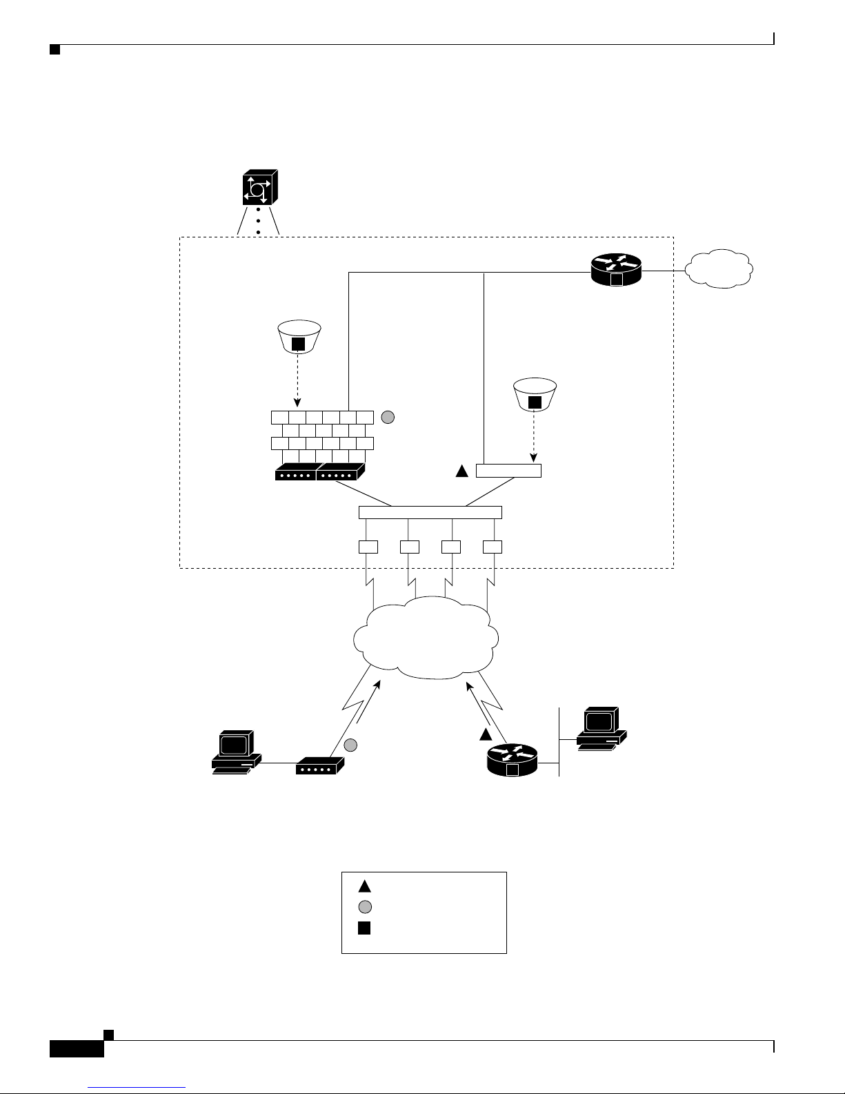
Figure 1-1 Cisco AS5350 and Cisco AS5400 Basic System Architecture
Cloning
Cloning
Asynchronous
interfaces
Group-async
interface
TTY lines
Modems
56092
Inside a Cisco
network gateway
Serial interface
channels S0:1, S0:2…
Dialer interface
controlling the
D channels
TDM bus
T1 controllers
PRI lines
POTS line BRI line
ISDN
router
Client
modem
Legend
Client
PC
Client
PC
= Synchronous PPP
= Asynchronous PPP
= Configuration
template
PSTN
Routing and
switching engine
IP
network
V
V
V
Page 23

1-3
Cisco AS5350 and Cisco AS5400 Universal Gateway Software Configuration Guide
OL-3418-02 B0
Chapter1 Understanding Basic Hardware Architecture and CiscoIOS Software
Exploring the CiscoIOS File System
Figure 1-1 shows the following:
• Client m o de m s and Int egr at ed Serv ice s D ig it al Networ k ( IS D N ) r outers dial into the ga teway
through the public switched telephone network (PSTN).
• Analog Point-to-Point Protocol (PPP) calls connect to modems inside the gateway.
• Each mode m inside the gateway provides a corresponding TT Y line and asynchronous inte rface for
terminating character and packet mode services.
• Asynchronous interfa ces clone their configurations from a group-async interface.
• Synchronous PPP calls connect to serial interface channels (for example, Se2/0:1 and Se2/0:2).
• Synchronous interfa ces clone their configurations from a dialer interface.
One analog PPP call uses the following resources:
• One T1 DS0 channel
• One chan n el i n a TDM bus
• One integ ra ted modem
• One TTY line
• One asynchronous interface
One synchronous PPP call uses the following resources:
• One T1 DS0 channel
• One serial interface channel
Exploring the Cisc oIOS File System
The Cisc o IOS F i le System (I FS ) f eat ure provides a single in ter fa ce to the following:
• Flash memory file system
• Network file system (TFTP, rcp, and FTP)
• Any othe r en dpo int fo r re adin g or writ ing da ta (su ch as NVR AM , mod em firmwa re , the runn in g
configurati o n, ROM, r aw sy s t em memory, Xmode m , a nd F l ash lo ad h el per log)
IFS fir st app eared i n Cisc o IOS Releases 11.3 AA and 12 .0. For more info rma tion about IFS, re fer t o the
chapter “Using the Cisco IOS F ile System” in the Cisco IOS Release 12 .0 Configuration Funda mentals
Configuration Guide, available online at
http:/ /www.cisco.com/univercd /c c/td/ do c /product/software/ios120/12cgcr /fun_c/fcprt2/fc ifs.htm
Page 24

1-4
Cisco AS5350 and Cisco AS5400 Universal Gateway Software Configuration Guide
OL-3418-02 B0
Chapter 1 Understanding Basic Hardware Architecture and CiscoIOS Software
Exploring the CiscoIOS File System
Figure 1-2 il lu str a t es t he m e m or y lo ca tions an d Table 1-1 des c ri be s th e m em o r y lo cat ions.
Figure 1-2 Cisco AS5350 and Cisco AS5400 Memory Locations
Table 1-1 Memory Location Descriptions
Component Description
CPU 250 MHz (Cisco AS5350 and Cisco AS5400)
390 MHz (Cisco AS5400HPX)
Processor memory The Cisco IOS image is initially read out of Flash
memory , decompres sed, an d loade d into pr ocesso r
memory (also known as main memory or DRAM).
Routing tables, c all control blocks, and other data
structures are also sto r ed h ere.
Packet I/O m em o ry Packets are temporar il y sto r ed in I /O memory.
System F la s h an d bo ot Flash mem or y Memory th at s tor es C isc o IOS i mag es , m odem
firmware/portware, and custom web pages.
NVRAM memo r y Nonvolatile configuration m em o r y th at retains its
contents whe n a unit is powered off.
CPU
(R7000)
System Flash
memory
35922
Processor
memory
Boot Flash
memory
Pocket I/O
memory
NVRAM
memory
Inside a Cisco
network gateway
V
Page 25

1-5
Cisco AS5350 and Cisco AS5400 Universal Gateway Software Configuration Guide
OL-3418-02 B0
Chapter1 Understanding Basic Hardware Architecture and CiscoIOS Software
Exploring the CiscoIOS File System
To inspect the file system, enter the show file systems command and the di r comm an d as s h own in th e
followi ng pr oc e d ur e .
Step 1 View the different file storage areas and file management functions:
Router# show file systems
File Systems:
Size(b) Free(b) Type Flags Prefixes
520184 520184 nvram rw nvram:
- - opaque rw null:
- - opaque rw system:
- - network rw tftp:
- - opaque wo vfc:
* 32768000 22992256 flash rw flash:
7602176 4634364 flash rw bootflash:
- - opaque wo lex:
- - network rw rcp:
- - network rw ftp:
In addition, verify that you have everything that you ordere d (for example, 32 megabytes of
Flash memo ry) . T he as t er isk (
*) indicat es t h e cu r re nt d irectory.
Step 2 Display the objects in the system me mory d irectory:
Router# dir system:
Directory of system:/
4 dr-x 0 <no date> memory
1 -rw- 5026 <no date> running-config
2 dr-x 0 <no date> ucode
14 dr-x 0 <no date> vfiles
Note Rememb er to include th e tr ailing co lo n ( :) in dir commands.
Step 3 Inspect t he co nt en ts o f b ootf l as h :
Router# dir bootflash:
Directory of bootflash:/
1 -rw- 1962796 Jan 01 2000 00:00:59 c5350-boot-mz.Jan7
2 -rw- 182684 Jun 05 2000 22:04:15 crashinfo_20000605-220415
3 -rw- 172464 Jun 26 2000 19:21:04 crashinfo_20000626-192104
5 -rw- 167594 Jun 26 2000 19:24:37 crashinfo_20000626-192437
6 -rw- 163300 Aug 02 2000 00:14:08 crashinfo_20000802-001408
7 -rw- 131250 Aug 02 2000 00:14:19 crashinfo_20000802-001419
8 -rw- 158171 Aug 08 2000 23:21:40 crashinfo_20000808-232140
7602176 bytes total (4634364 bytes free)
In the exampl e, th e bo o tflash image is c5350-boot-mz.Jan7. The compressed file size is 1962796 bytes.
The total Boot Flash memory size is
7602176 bytes. The number of fr ee bytes is 4634364. The crashi nfo
file is a collection of useful information related to the current crash stored in Boot Flash or Flash
memory.
Note For more information on crashinfo files, refer to Retrie ving Informat ion fr om th e Crashi nfo F ile ,
available onli ne at
http://www.cisco.com/warp/public/63/cra shinfo.html.
Page 26

1-6
Cisco AS5350 and Cisco AS5400 Universal Gateway Software Configuration Guide
OL-3418-02 B0
Chapter 1 Understanding Basic Hardware Architecture and CiscoIOS Software
Exploring CiscoIOS Software
Step 4 Display t he conten ts of F l ash m e m ory :
Router# pwd
flash:
Router# dir
1 -rw- 9950528 Jan 01 2000 00:48:59 c5350-js-mz.121-1.XD1.bin
32768000 bytes total (22817344 bytes free)
The Cisco IOS image named c5350-js-mz.121-1.XD1.bin is present.
Step 5 Inspect the NVRAM directory:
Router# dir nvram:
Directory of nvram:/
1 -rw- 0 <no date> startup-config
2 ---- 0 <no date> private-config
520184 bytes total (520184 bytes free)
In the exampl e, th e star tu p -c on fig and private-co nfi g are pr esent. The private-co n fig file is a secu re file
that is part of the startup c onfiguration. It supports encryption technologies , but it is not us er accessible.
Exploring Cisco IOS Software
This section describes what you need to know about the Cisco IOS software (the software that runs the
gateway) before you configure the gateway using the CLI. This section includes:
• Gettin g H e lp , page 1- 6
• Under sta ndi ng Com m and M od es, pa ge 1-7
• Finding Command Options, page 1-7
• Undoing a Command or Feature, page 1-9
• Saving Configuration Changes, page 1-10
Underst andi ng th ese con cept s sa v es you time if you ha v e no or minim al e xperi e nce usi ng th e Cisco IOS
software.
Getting Help
Use the question mark (?) and arrow keys t o help you enter co m mands, where Router> is t he prompt for
the top level of the Cisco IOS software for the Cisco AS5350 or Cisco AS5400 universal gateway.
Note The examples in this guide show prompts for either a Cisco AS5350 or a Cisco AS5400 gateway.
However, regardless of the prompt or output shown, all examples apply to either type of gatewa y.
Page 27

1-7
Cisco AS5350 and Cisco AS5400 Universal Gateway Software Configuration Guide
OL-3418-02 B0
Chapter1 Understanding Basic Hardware Architecture and CiscoIOS Software
Exploring CiscoIOS Software
• For a list of avail ab le co mm an d s, e nt er a q u es t io n m ar k:
Router> ?
• T o co mp le t e a c om man d, en te r a few known ch ar act er s f ol lowed by a q u est io n m ar k (with no space ):
Router> s?
• For a list of command variables, enter the show command followed by a space and a question mark:
Router> show ?
• To redisplay a command you previously entered, press the up arrow key. You can continue to press
the up arrow key for more commands.
Understan di ng C om man d Modes
Y ou need to use many different command modes to configure the gateway. Each command mode restricts
you to a subset of commands.
Tip If you are having trouble ente ring a command, check the prompt, and then enter the question mark (?)
for a list of available commands. You might be in the wrong command mode or us ing the wrong syntax.
In the fol lowin g example, no ti ce h ow th e prompt ch an g es a ft er ea ch co mm a nd t o in di cat e a new
command mode:
Router> enable
Router> password
Router# configure terminal
Router(config)# interface fastethernet 0/0
Router(config-if)# ip address 172.16.254.250
Router(config-if)# exit
Router#
%SYS-5-CONFIG_I: Configured from console by console
The last message is normal and does not in dicate a n error. Press Return to get the Router> prompt.
Note You can press Ctrl-Z at any time to im med i ately retu r n to en ab le m o de ( Router#), instead of entering
exit, wh ic h return s y o u t o the previo us m o de .
Finding Com ma nd O pt i ons
This sectio n e x pl a i ns how to dis p lay op ti ons fo r a c om mand. To display o ptions for a comm a n d , e nter
a ? at t he co nfigu r at io n pr ompt, or af ter enterin g p ar t o f a c om m an d followed by a sp ace. The
configuration parser displays options available with the command. For example, if you were in global
configurati on mode, ty pe d th e comman d arap, and wanted to see all the keywords and arguments for
that comma nd , y o u would type arap ?
Page 28

1-8
Cisco AS5350 and Cisco AS5400 Universal Gateway Software Configuration Guide
OL-3418-02 B0
Chapter 1 Understanding Basic Hardware Architecture and CiscoIOS Software
Exploring CiscoIOS Software
Command Purpose
Step 1
Router> enable
Password:
password
Router#
Enters enable mode. Enters the
password. You are in enable mode when
the prom pt ch an g es to
Router#.
Step 2
Router# config terminal
Enter configuration commands, one per line. End with
CNTL/Z.
Router(config)#
Enters g lobal configu r ation m ode. You
are in global configur a t io n mode when
the prompt changes to
Router(config)#.
Step 3
Router(config)# controller t1 1/?
<0-1> Controller port number
Router(config)# controller t1 1/0
Specif ie s t he T1 co ntrol le r th at y ou wa nt
to configure using the controller T1
number global configuration command.
Step 4
Router(config-controller)# ?
Controller configuration commands:
Displa ys c on t ro ll er configuration
commands.
cablelength
channel-group
default
description
ds0
ds0-group
exit
fdl
framing
help
linecode
loopback
no
pri-group
shutdown
Specify cable length for a
DS1 link
Specify timeslots to
channel-group mapping for an
interface
Set a command to its defaults
Controller specific
description
ds0 commands
Replacement of cas-group
Configure group of timeslots
to a particular signaling
type
Exit from controller
configuration mode
Specify the FDL standard for
a DS1 data link
Specify the type of Framing
on a DS1 link
Description of the
interactive help system
Specify the line encoding
method for a DS1 link
Put the entire T1 line into
loopback
Negate a command or set its
defaults
Configure the specified
timeslots for PRI
Shut down a DS1 link (send
Blue Alarm)
Step 5
Router(config-controller)# ds0-group ?
<0-23> Channel number
Displays the options for the ds0-group
controller co nfigur ati on co mm an d . This
command i s us ed to co n fig ure the
channel-as soci ated sig naling on a T1
controller.
Step 6
Router(config-controller)# ds0-group 1 ?
timeslots List of timeslots in the ds0-group
Displays the only command (timeslots)
available in ds0 -group 1.
Page 29

1-9
Cisco AS5350 and Cisco AS5400 Universal Gateway Software Configuration Guide
OL-3418-02 B0
Chapter1 Understanding Basic Hardware Architecture and CiscoIOS Software
Exploring CiscoIOS Software
Undoing a C om man d or Feature
If you want to undo a command you entered or disable a feature, enter the keyword no before most
command s; for example, no ip routing.
Step 7
Router(config-controller)# ds0-group 1 timeslots ?
<1-24> List of timeslots which comprise the
ds0-group
Displays the range for the timeslot
option. Specif y a timeslo t range of
values from 1 to 24. You can specify
timeslot ra n ge s ( fo r e xa m ple, 1- 2 4) ,
individual timeslots separated by
commas (fo r exampl e 1 , 3, 5), or a
combination of the two (for example 1-3,
8, 17-2 4) . The 1 6t h timeslot is n o t
specified in the command line, because it
is rese rved f or t ra ns mitting the channel
signaling.
Step 8
Router(config-controller)# ds0-group 1 timeslots
1-24 ?
Display s the two com mands (service and
type) available for th e timeslo ts .
service
type
Specify the type of service
Specify the type of signaling
Step 9
Router(config-controller)# ds0-group 1 timeslots
1-24 type ?
Lists supported signaling type s.
e&m-fgb
e&m-fgd
e&m-immediate-start
fxs-ground-start
fxs-loop-start
sas-ground-start
sas-loop-start
E & M Type II FGB
E & M Type II FGD
E & M Immediate Start
FXS Ground Start
FXS Loop Start
SAS Ground Start
SAS Loop Start
Step 10
Router(config-controller)# ds0-group 1 timeslots
1-24 type e&m-fgb ?
dtmf DTMF tone signaling
mf MF tone signaling
service Specify the type of service
<cr>
Displays the types of channel-associated
signaling available for the e&m-fgb
type.
Step 11
Router(config-controller)# ds0-group 1 timeslots
1-24 type e&m-fgb dtmf ?
dnis DNIS addr info provisioned
service Specify the type of service
<cr>
Displays the options supported for the
DTMF tone signaling option.
Command Purpose
Page 30

1-10
Cisco AS5350 and Cisco AS5400 Universal Gateway Software Configuration Guide
OL-3418-02 B0
Chapter 1 Understanding Basic Hardware Architecture and CiscoIOS Software
Upgradi ng to a New CiscoIOS Release
Saving Con f i guration Changes
Enter the copy running-config startup-config command to save your configuration changes to
nonvolatile ran dom - ac ces s m emo r y (N V R A M ) s o t ha t t h ey ar e no t lo st i f th er e i s a system relo ad o r
power outage. For exampl e:
Router# copy running-config startup-config
Building configuration...
It might take a minute or two to save the configuration to NVRAM. After the configuration has been
saved, the fo ll owi ng appears:
[OK]
Router#
Timesaver You can u se t h e q ue s ti on mark (?) and arrow keys to help you enter commands.
Timesaver Each co mm an d mo de r es t ricts yo u to a s et of c om m an ds. I f yo u are h avi ng d ifficul ty en tering a
command, check the pr ompt and then enter the question mark (?) for a list of available commands . You
might be in the wrong command mode or using the wrong syntax.
Timesaver If you want to dis able a featur e, enter the keyword no before the command; for example, no ip routing.
Timesaver You ne ed to s ave y o ur c on fig ur at io n ch anges to N V R A M s o th at th ey are not lo s t if th er e is a s y s tem
reload or power outage.
Upgrading to a New Ci scoIOS Rel ease
Obtain n ew Cisco IOS fe atu r es and mor e st ab le code by u pg r adi n g t o a n ew Cis c o IOS re lea s e.
Step 1 Display t he conten ts of F l ash m e m ory :
Router# cd flash:
Router# dir
Directory of flash:/
1 -rw- 9950528 Jan 01 2000 00:48:59 c5350-js-mz.121-1.XD1.bin
32768000 bytes total (13041600 bytes free)
Step 2 Copy the new image from the remote TFTP server into Flash memory. Make sur e that you specify your
own TFTP server’s IP addres s and Ci sco IOS file name. If yo u encoun ter iss ues with upgrad ing th e
image, b e su r e t ha t y o u can p in g th e T F TP se rve r an d th at appropr ia te di re cto ry pe rmissions ar e
configured on the TFTP server. To see the bangs (!) during the download operation, enable line wrap in
your terminal emulation software.
Page 31

1-11
Cisco AS5350 and Cisco AS5400 Universal Gateway Software Configuration Guide
OL-3418-02 B0
Chapter1 Understanding Basic Hardware Architecture and CiscoIOS Software
Upgrading to a New CiscoI OS Release
Note If you h ave availabl e sp ace for two images, leave b o th images in F lash memory. If necess ar y,
you can easily revert back to the previous image. Enter the boot system flash newiosname.bin
comm an d to p oi nt to the n ew image file n ame. By de fau lt , the first im a ge in Fla s h m emory is
loaded.
If you do not have available space, during the copy operation the system displays a message
telling you to delete the current file and squeeze the flash to make room for the new image. Enter
the delete flash:version command, foll owe d by the squeeze flash command, to perform this
delete -and - squ ee ze operatio n. Then p roceed wit h th e c opy o p e ration.
Router# copy tftp flash
Address or name of remote host [172.22.191.135]? 172.22.191.135
Source filename [c5350-js-mz.121-1.XD1.bin]? c5350-js-mz.121-3.T.bin
Destination filename [c5350-js-mz.121-3.T.bin]?
Accessing tftp://172.22.191.135/c5350-js-mz.121-3.T.bin...
Loading c5350-js-mz.121-3.T.bin from 172.22.191.135 (via FastEthernet0/0): !!!!!
!!!!!!!!!!!!!!!!!!!!!!!!!!!!!!!!!!!!!!!!!!!!!!!!!!!!!!!!!!!!!!!!!!!!!!!!!!!!!!!!
!!!!!!!!!!!!!!!!!!!!!!!!!!!!!!!!!!!!!!!!!!!!!!!!!!!!!!!!!!!!!!!!!!!!!!!!!!!!!!!!
!!!!!!!!!!!!!!!!!!!!!!!!!!!!!!!!!!!!!!!!!!!!!!!!!!!!!!!!!!!!!!!!!!!!!!!!!!!!!!!!
!!!!!!!!!!!!!!!!!!!!!!!!!!!!!!!!!!!!!!!!!!!!!!!!!!!!!!!!!!!!!!!!!!!!!!!!!!!!!!!!
!!!!!!!!!!!!!!!!!!!!!!!!!!!!!!!!!!!!!!!!!!!!!!!!!!!!!!!!!!!!!!!!!!
[OK - 9775616/19551232 bytes]
9775616 bytes copied in 66.424 secs (148115 bytes/sec)
Caution Occasionally TFTP errors occur. Make sure that the verifying checksum reports “OK.” Do not reload the
gateway if the checksum reports errors.
Step 3 Verif y th at t he new image w as d ownlo ad ed . I n th i s exam pl e, notice th at th e Cisco IOS Release
12.1(1)XD im age is the first in Flash memory, so it is loaded during the boot sequence. To boot using
the new image, yo u mu st ei th er del et e th e un wa nt ed imag e o r u se th e bo ot system command to specify
the alternate image to use during the boot sequence.
Router# dir flash:
Directory of flash:/
1 -rw- 9950528 Jan 01 2000 00:48:59 c5350-js-mz.121-1.XD1.bin
2 -rw- 9775616 Jan 01 2000 00:59:10 c5350-js-mz.121-3.T.bin
32768000 bytes total (13041600 bytes free)
For mo re in for ma tio n on del et ing the imag e, re fe r to the do cu me nt Cisco IOS File System, available
onlin e at
http:/ /w w w.cisco.com/u nivercd/cc/td/doc/produ ct/software/ios 1 13ed/11 3aa/113 aa_2/allp lats/if s .ht m
Note The Ci s co A S 5 350 an d Ci s co A S 5 400, u nl ike the Ci s co A S 52 00 an d C isco AS5300, use a
Class A Flash File System.
Page 32

1-12
Cisco AS5350 and Cisco AS5400 Universal Gateway Software Configuration Guide
OL-3418-02 B0
Chapter 1 Understanding Basic Hardware Architecture and CiscoIOS Software
Upgradi ng to a New CiscoIOS Release
Step 4 To specif y th e alternate im a ge th at is to b e u s ed d uring the bo o t se qu en ce use t he boot system flash
newios name .bin comman d to sp eci fy t he lo ca tio n ( devi ce) a nd n ame of th e i mag e t o be u s ed :
Router(config)# boot system flash c5350-js-mz.121-3.T.bin
Router(config)# ^Z
Router# copy running-config startup-config
Destination filename [startup-config]?
Building configuration...
[OK]
To verify th at this c om m an d is in effect , u se t he show running-configuration command . Save yo ur
running configura tion before the reload so that the gateway loads the correct image.
Step 5 Reload the Cisco AS5350 or Cisco AS5400 to run the new image. If you erased the old Cisco IOS image,
make sure that the boot sy stem flash ol diosna me.bin command is not enabled and pointing to the old
image file name; otherwise, the gateway gets stuck trying to reload the old im age over and over again.
Router# reload
Proceed with reload? [confirm]
System Bootstrap, Version 12.0(20000106:234457) [tombnyg-rommon_1_6 106],
SOFTWARE REV 1.6
Copyright (c) 1994-2000 by cisco Systems, Inc.
AS5400 platform with 131072 Kbytes of main memory
Self decompressing the image : #################################################
##################################################### [OK]
Self decompressing the image : #################################################
################################################################################
################################################################################
################################################################################
################################################################################
################################################################### [OK]
Press RETURN to get started!
Note Most sections of t he bo o t se qu en ce h ave be en o m it ted f r om th e ex am p le .
For more information about TFTP, refer to the document Loading and Maintaining System Images
and Microcode, available online at
http:/ /www.cisco. com/u nive r c d/cc/t d/doc/ product/software /ios12 0/12cg cr/fun_c/fc pr t2/fc im ages .htm
Tip On sys t e m relo ad, if t he c o n s ole se ss io n free z es or d i splays unus ual cha racters on the sc r een, yo u m ay
have a consol e session mismatch be tw ee n t h e C isco I O S console lin e speed an d th e t e rm in al se rver
speed. T his mis match may occ ur becaus e o f t he pr ogr am se tti ng s of you r con sol e or you r t ermina l serv e r
speed.
Note Before you pro cee d to correct ses sio n mismat ch, v e rify tha t your pr oble m is not due to a defe ctive cable
or improp er cable con n ect io n. Ch ec k yo u r cab le co nn ec ti on o r repl ace cable a nd r el oa d s ys t em again.
Page 33

1-13
Cisco AS5350 and Cisco AS5400 Universal Gateway Software Configuration Guide
OL-3418-02 B0
Chapter1 Understanding Basic Hardware Architecture and CiscoIOS Software
Upgrading to a New CiscoI OS Release
To correct a console session mismatch, do one of the following:
• Change your console line speed.
• Change y o ur terminal s er ver speed.
• If the ab ove tw o so lutions do n ot co r rect consol e s es s io n, in s ta ll th e console ju m p er on the
motherboard to set your default console port speed to 9600 bps.
For Re v isi on 1 mot herb oa rds, th e jum per is se t at m othe rbo ar d pin lo ca tion or ro w J3, wh ere th e t op
two pi ns (t ow ar d t he ba ck of t he boa rd ) are ju mper ed. F or Re vi sio n 3 mot her boa rds, pi ns 1 and 2 f or
row J1 m u s t be shor ted ou t.
Changing C onsole Line Speed
Caution Changing your console line speed on an active Cisco AS5350 or Cisco AS5400 results in a temporary
loss of synchronization between the console line and terminal port speeds. At this point the gateway may
recogniz e a fa ls e send break command that may result in your system crashing.
To avoid this problem, you can do one of the following:
• If the configuration register on your Cisco AS5350 or Cisco AS5400 already has the Break Abort
Effect bit set (mask is 0x0100) , then you ar e protec ted and the false s end break eve nt does not occur .
(You can change the configuration register to have this bit set, but the change does not take effect
until your gateway is rebooted.)
• If the c o n fig ur a t ion reg is t e r d oes not ha ve the Break Abort Effect bit set (mask 0x0100), then
disconnect the cable on the console port and either log into the Cisco AS5350 or Cisco AS5400
through the AUX port or telnet in through a VTY session. Change the console line speed and the
related t e rm in al s erver speed, th en r eco n ne ct the con s o le cab le .
Log in to your Cisco AS5350 or Cisco AS5400 through the AUX port or Telnet VTY session. Enter the
show running-config command and determine what speed your line console is set. Possible console
speeds are 1200, 2400, 4800, 9600, 19200, 38400, 57600, and 115200. The default setting is 9600.
If your gatewa y is in ROM monitor m ode, then the AUX port is not functioning. You must then change
the terminal server port speed through your console port connection until the
rommon> prompt is
displayed. See Appendix B, “ROM Monitor.”
Changing G at ew ay Line Speed
The following exa mple shows how to configure line speed on a Cisco AS5350 or Cisco AS5400,
beginning in global configuration mode:
Router(config)# line 3
Router(config-line)# speed speed_value
Page 34

1-14
Cisco AS5350 and Cisco AS5400 Universal Gateway Software Configuration Guide
OL-3418-02 B0
Chapter 1 Understanding Basic Hardware Architecture and CiscoIOS Software
Where to Go Next
Where to Go Next
At this point you should go to:
• Chapter 2, “Verifying Basic Setup” to an al yz e y o ur s y ste m an d execu te b asic tasks an d sys t em
configuration before configuring the Cisco AS5350 or Cisco AS5400 universal gateway using the
CLI. To commission is to systematically execute basic configuration tasks that prepare your system
for data call processing.
Tip The foll owing publication s are available on the Documentation CD-ROM that came with your gateway,
or on th e World Wide Web from the C is co hom e page .
• Cisco IOS publications Dial Solutions Configuration Guide and Dial Solutions Command Reference
provide a ddit io n a l ba s ic-co n fig uration in fo rm at io n. Fo r m o r e ad van ced c on fig uration to p ics, refer
to the Cisco IOS software configuration guide, feature modules, and command reference
publicat ions th at pert ain to you r Cisco IOS soft ware relea se.
• Check Configuring Se lected 12.1 Cisco IOS Software Fe atures, available online at
http://www.cisco.com/univercd/cc/td/doc/product/access/acs_serv/as5400/index.htm
• For troubleshooting information, refer to the System Error Messages and Debug Command
Reference publications.
Page 35

CHAPTER
2-1
Cisco AS5350 and Cisco AS5400 Universal Gateway Software Configuration Guide
OL-3418-02 B0
2
Verifying Basic Setup
Note The information herein applies to the Cisco AS5350, Cisco AS5400, and Cisco AS5400HPX universal
gateways. No te that th e l at ter r eq u ir es u s e of C isco IOS rel ease 1 2.2(2)XB o r lat er.
This chapter details the tasks required to verify that your basic system components are function ing
normally:
• Analyzing the System Boot Dialog, page 2-1
• Checking the Initial Running Configuration, page 2-5
• Investigating Memory Usage, page 2-7
• Inspecting CPU Utilization, page 2-8
Analyzing the Syst em Boot Dialog
The Cisc o AS5350 and Cisco AS5400 ha v e a spe c ifi c bo ot s eque nce. To view the b oot s equ en ce t hro ugh
a terminal session, you must have a console connection to the gatewa y before it powers up.
Note If you observe no messages on the console port, check that the baud rate is configured correctly. The
Cisco AS5350 and Cisco AS5400 console port can support a baud rate up to 115200.
The following boot sequence occurs. Step numbers and comments are inserted in the example to describe
the boot sequence.
Step 1 In the following segment, the gateway decompresses the system boot image, t ests the NVR A M for
validity, and decompr ess es the C i s co I O S image .
System Bootstrap, Version 12.0(20000106:234457) [tombnyg-rommon_1_6 106],
SOFTWARE REV 1.6
Copyright (c) 1994-2000 by cisco Systems, Inc.
AS5350 platform with 131072 Kbytes of main memory
Self decompressing the image : #################################################
##################################################### [OK]
Self decompressing the image : #################################################
################################################################################
################################################################### [OK]
Page 36

2-2
Cisco AS5350 and Cisco AS5400 Universal Gateway Software Configuration Guide
OL-3418-02 B0
Chapter 2 Verifying Basic Setup
Analyzing the System Boot Dialog
Step 2 Cisco IOS re le ase, available memory, hardware in terfaces, a nd m o d em lines ar e d isp la ye d:
Note If a card type is not recognized, verify that you are running the optimum version of Cisco IOS
softwar e . R ef er t o the hard war e- s o f twa re co m p at ib ility ma tr ix , avail able onli ne at
http://cco-sj-1.cisco.com/cgi-bin/front.x/Support/HWSWmatrix/hwswmatrix.cgi
Restricted Rights Legend
Use, duplication, or disclosure by the Government is
subject to restrictions as set forth in subparagraph
(c) of the Commercial Computer Software - Restricted
Rights clause at FAR sec. 52.227-19 and subparagraph
(c) (1) (ii) of the Rights in Technical Data and Computer
Software clause at DFARS sec. 252.227-7013.
cisco Systems, Inc.
170 West Tasman Drive
San Jose, California 95134-1706
Cisco Internetwork Operating System Software
IOS (tm) 5350 Software (C5350-JS-M), Version 12.1(3)T, RELEASE SOFTWARE (fc1)
Copyright (c) 1986-2000 by cisco Systems, Inc.
Compiled Thu 20-Jul-00 03:02 by ccai
Image text-base: 0x60008968, data-base: 0x61000000
cisco AS5400 (R7K) processor (revision O) with 131072K/65536K bytes of memory.
Processor board ID JAB0351040G
R7000 CPU at 250Mhz, Implementation 39, Rev 1.0, 256KB L2, 2048KB L3 Cache
Last reset from IOS reload
Bridging software.
X.25 software, Version 3.0.0.
SuperLAT software (copyright 1990 by Meridian Technology Corp).
TN3270 Emulation software.
Primary Rate ISDN software, Version 1.1.
Manufacture Cookie Info:
EEPROM Type 0x0001, EEPROM Version 0x01, Board ID 0x31,
Board Hardware Version 3.21, Item Number 800-5171-01,
Board Revision 017, Serial Number JAB0351040G,
PLD/ISP Version 1.0, Manufacture Date 6-Jan-2000.
Processor 0xFF, MAC Address 0x03096F818
Backplane HW Revision FF.FF, Flash Type 5V
2 FastEthernet/IEEE 802.3 interface(s)
2 Serial network interface(s)
108 terminal line(s)
8 Channelized T1/PRI port(s)
512K bytes of non-volatile configuration memory.
32768K bytes of processor board System flash (Read/Write)
8192K bytes of processor board Boot flash (Read/Write)
Step 3 Because th e g atewa y h as never b een co nfigured, it can n ot fin d a st ar tu p- co n fig fil e. Therefor e, the
software asks, “Would you like to enter the initial configuration dialog? [yes/no]”
Enter no. In this example, the Cisco IOS software is configured manually. The automatic setup script is
not used. Configuring the Cisco IOS software manually develops your expertise.
Enter yes to terminate autoin stall.
--- System Configuration Dialog ---
Would you like to enter the initial configuration dialog? [yes/no]: no
Would you like to terminate autoinstall? [yes]: yes
Page 37

2-3
Cisco AS5350 and Cisco AS5400 Universal Gateway Software Configuration Guide
OL-3418-02 B0
Chapter 2 Veri fy in g Basi c Setu p
Analyzing the System Boot Dialog
Step 4 This examp le sh ows t he LA N i nt erfac es a nd t he slo ts in w h ich p o rt ca rd s ar e no t in s erted. The
univ ersa l -port -c ard (fo rmer ly call ed Ne xtPor t) modul e f irm war e v ersi on i s disp la yed (v ers ion 1.1 .6. 81) .
The gateway attempts to switch to a better clock source but does not find a suitable source because the
T1s are not ye t config ured .
00:00:03: %NP_MD-6-SLOT_INSERTED: Slot 1 (108 ports max) inserted
00:00:16: %CARRIER-3-NO_DFC: DFC is not present - DFC 3
00:00:16: %CARRIER-3-NO_DFC: DFC is not present - DFC 4
00:00:16: %CARRIER-3-NO_DFC: DFC is not present - DFC 5
00:00:16: %CARRIER-3-NO_DFC: DFC is not present - DFC 6
00:00:16: %CARRIER-3-NO_DFC: DFC is not present - DFC 7
00:00:19: %LINK-3-UPDOWN: Interface FastEthernet0/0, changed state to up
00:00:19: %LINK-3-UPDOWN: Interface FastEthernet0/1, changed state to up
00:00:19: %LINK-3-UPDOWN: Interface Serial0/0, changed state to down
00:00:19: %LINK-3-UPDOWN: Interface Serial0/1, changed state to down
00:00:20: %LINEPROTO-5-UPDOWN: Line protocol on Interface FastEthernet0/0, changed state
to up
00:00:20: %LINEPROTO-5-UPDOWN: Line protocol on Interface FastEthernet0/1, changed state
to down
00:00:20: %LINEPROTO-5-UPDOWN: Line protocol on Interface Serial0/0, changed state to down
00:00:20: %LINEPROTO-5-UPDOWN: Line protocol on Interface Serial0/1, changed state to down
00:00:23: %NP_BS-6-MODULE_STARTED: NextPort module 1/0/0 Started - 1.1.6.81
00:00:26: %NP_BS-6-MODULE_STARTED: NextPort module 1/0/1 Started - 1.1.6.81
00:00:30: %NP_MD-6-MODULE_UP: NextPort module 1/0/0 up
00:00:30: %NP_BS-6-MODULE_STARTED: NextPort module 1/0/2 Started - 1.1.6.81
00:00:33: %NP_MD-6-MODULE_UP: NextPort module 1/0/1 up
00:00:37: %NP_MD-6-MODULE_UP: NextPort module 1/0/2 up
00:01:05: %LINK-5-CHANGED: Interface Serial0/0, changed state to administratively down
00:01:05: %LINK-5-CHANGED: Interface FastEthernet0/0, changed state to administratively
down
00:01:05: %LINK-5-CHANGED: Interface FastEthernet0/1, changed state to administratively
down
00:01:05: %LINK-5-CHANGED: Interface Serial0/1, changed state to administratively down
00:01:06: %LINEPROTO-5-UPDOWN: Line protocol on Interface FastEthernet0/0, changed state
to down
00:01:10: %SYS-5-RESTART: System restarted -Cisco Internetwork Operating System Software
IOS (tm) 5350 Software (C5350-JS-M), Version 12.1(1)XD1, EARLY DEPLOYMENT RELEASE SOFTWARE
(fc2)
TAC:Home:SW:IOS:Specials for info
Copyright (c) 1986-2000 by cisco Systems, Inc.
Compiled Sun 09-Jul-00 07:06 by beliu
00:01:10: %TRUNK_CLOCK-6-SWITCH: Switching to the clock on slot 2 port 1 priority 205 as
the current primary has gone bad
00:01:10: %TRUNK_CLOCK-6-SWITCH: Switching to the clock on slot 2 port 2 priority 204 as
the current primary has gone bad
00:01:10: %TRUNK_CLOCK-6-SWITCH: Switching to the clock on slot 2 port 3 priority 205 as
the current primary has gone bad
00:01:10: %TRUNK_CLOCK-6-SWITCH: Switching to the clock on slot 2 port 4 priority 204 as
the current primary has gone bad
00:01:10: %TRUNK_CLOCK-6-SWITCH: Switching to the clock on slot 2 port 5 priority 205 as
the current primary has gone bad
00:01:10: %TRUNK_CLOCK-6-SWITCH: Switching to the clock on slot 2 port 6 priority 204 as
the current primary has gone bad
00:01:10: %TRUNK_CLOCK-6-SWITCH: Switching to the clock on slot 2 port 7 priority 205 as
the current primary has gone bad
00:01:10: %TRUNK_CLOCK-6-BAD_CLOCKS: There are no good clocks in the system. Remain in
HOLDOVER mode
00:01:10: %TRUNK_CLOCK-6-BAD_CLOCKS: There are no good clocks in the system. Remain in
HOLDOVER mode
00:01:10: %TRUNK_CLOCK-6-BAD_CLOCKS: There are no good clocks in the system. Remain in
HOLDOVER mode
Page 38

2-4
Cisco AS5350 and Cisco AS5400 Universal Gateway Software Configuration Guide
OL-3418-02 B0
Chapter 2 Verifying Basic Setup
Analyzing the System Boot Dialog
00:01:10: %TRUNK_CLOCK-6-BAD_CLOCKS: There are no good clocks in the system. Remain in
HOLDOVER mode
00:01:10: %TRUNK_CLOCK-6-BAD_CLOCKS: There are no good clocks in the system. Remain in
HOLDOVER mode
Step 5 Enter the show v ers i on comman d to c he ck th e s y st em h ar d wa re , C isco IOS i m ag e n ame, uptime, and
restart reas on :
Router> show version
Cisco Internetwork Operating System Software
IOS (tm) 5350 Software (C5350-JS-M), Version 12.1(20001028:174051)]
Copyright (c) 1986-2001 by cisco Systems, Inc.
Compiled Mon 19-Feb-01 04:10 by
Image text-base: 0x60008968, data-base: 0x61180000
ROM: System Bootstrap, Version 12.0(19991122:230447)
BOOTFLASH: 5350 Software (C5350-BOOT-M), Version 12.0(19991112:131]
AS5400 uptime is 1 day, 4 hours, 29 minutes
System returned to ROM by reload at 12:34:33 UTC Tue Nov 30 1999
System image file is "flash:c5350-js-mz.xm.Feb19"
cisco AS5400 (R7K) processor (revision L) with 131072K/65536K bytes of memory.
Processor board ID 99290068
R7000 CPU at 250Mhz, Implementation 39, Rev 1.0, 256KB L2, 2048KB L3 Cache
Last reset from warm-reset
Bridging software.
X.25 software, Version 3.0.0.
SuperLAT software (copyright 1990 by Meridian Technology Corp).
TN3270 Emulation software.
Primary Rate ISDN software, Version 1.1.
Manufacture Cookie Info:
EEPROM Type 0x0001, EEPROM Version 0x01, Board ID 0x31,
Board Hardware Version 1.21, Item Number 800-5171-01,
Board Revision 011, Serial Number 99290068,
PLD/ISP Version 0.0, Manufacture Date 2-Aug-1999.
Processor 0xFF, MAC Address 0x0503EFF5F4C
Backplane HW Revision FF.FF, Flash Type 5V
2 FastEthernet/IEEE 802.3 interface(s)
2 Serial network interface(s)
108 terminal line(s)
8 Channelized T1/PRI port(s)
512K bytes of non-volatile configuration memory.
16384K bytes of processor board System flash (Read/Write)
8192K bytes of processor board Boot flash (Read/Write)
Configuration register is 0x2102
Table 2-1 describes the significant output fields in the prev ious example.
Page 39

2-5
Cisco AS5350 and Cisco AS5400 Universal Gateway Software Configuration Guide
OL-3418-02 B0
Chapter 2 Veri fy in g Basi c Setu p
Checking the Initia l Runni ng Configuration
Checking the Initial Running Confi gur ation
The Cisco IOS software creates an initial running configuration. Inspect the configuration to get familiar
with the default sett in gs . U s er in p ut is s how n in b ol df ace type.
Router> enable
Password:
Router# show running-config
Building configuration...
Current configuration : 7653 bytes
!
version 12.1
no service single-slot-reload-enable
no service pad
service timestamps debug uptime
service timestamps log uptime
no service password-encryption
!
hostname Router
!
no boot startup-test
logging rate-limit console 10 except errors
!
!
resource-pool disable
!
!
voice-fastpath enable
ip subnet-zero
no ip routing
no ip finger
ip name-server 172.16.11.48
ip name-server 172.16.2.132
ip name-server 172.16.2.133
!
call rsvp-sync
!
!
fax interface-type modem
mta receive maximum-recipients 0
!
!
controller T1 1/0
!
controller T1 1/1
Table 2-1 Show Version Command Field Descriptions
Field Description
AS5400 uptime is....
Watch for unsch ed ul ed r elo ad s by in s p ect in g th is
field .
System returned to ROM by reload at....
Tells you why the gateway last reloaded. If the
field displays “pow er-on,” a power in terruption
caused the rel oad.
System image file is....
The gat eway bo o ted from th is im a ge loca tio n .
Page 40

2-6
Cisco AS5350 and Cisco AS5400 Universal Gateway Software Configuration Guide
OL-3418-02 B0
Chapter 2 Verifying Basic Setup
Checking the Initia l Running Configurati on
!
controller T1 1/2
!
controller T1 1/3
!
controller T1 1/4
!
controller T1 1/5
!
controller T1 1/6
!
controller T1 1/7
!
!
interface FastEthernet0/0
ip address 172.21.101.21 255.255.255.0
no ip route-cache
no ip mroute-cache
duplex auto
speed 100
no mop enabled
!
interface FastEthernet0/1
no ip address
no ip route-cache
no ip mroute-cache
shutdown
duplex auto
speed auto
!
interface Serial0/0
no ip address
no ip route-cache
no ip mroute-cache
shutdown
fair-queue
clockrate 2000000
!
interface Serial0/1
no ip address
no ip route-cache
no ip mroute-cache
shutdown
clockrate 2000000
!
interface Async4/00
no ip address
no ip route-cache
!
interface Async4/01
no ip address
no ip route-cache
!
interface Async4/02
no ip address
no ip route-cache
.
.
.
interface Async4/107
no ip address
no ip route-cache
!
Page 41

2-7
Cisco AS5350 and Cisco AS5400 Universal Gateway Software Configuration Guide
OL-3418-02 B0
Chapter 2 Veri fy in g Basi c Setu p
Investigating Memory Usage
interface Group-Async0
no ip address
no ip route-cache
no group-range
!
ip kerberos source-interface any
ip classless
no ip http server
!
!
line con 0
logging synchronous
transport input none
line aux 0
logging synchronous
line vty 0 4
password cisco
login
line 4/00 4/107
no flush-at-activation
modem InOut
!
scheduler allocate 10000 400
end
The Cisco AS5 35 0 or Ci s co AS 5 400 di s play s every asyn ch r ono us i nt er fac e it re co gnizes. Theref o re, if
your sys tem ha s a lar ge numb er of a syn ch ronous int e rfac es , the runni ng -conf i gu rati on will b e v ery lo ng.
To aggregat e t he asy n ch ro n ous i nt er faces , yo u mu s t a ss ign th em to a G r o up -A s ync Interface using th e
command group-range. See the “Configuring the Asynchronous Group Interface” secti on on page 3-7 .
Group-async interfaces are templates used to control the configuration of multiple asynchronous
interfaces on the gateway. Each asynchronous interface corresponds to one of the modem lines and uses
the same number as its co rr esp o nd i ng li n e. C o nfigu r in g th e asynchron ou s i nt er fa ces as a gro up - asy nc
saves you time and configuration file size.
Investigating Memory Usage
Use the show mem ory su mmary command to :
• Understand how memory is used for different processor and I/O memory processes.
• Identify memory fragmentation and memory leaks.
–
Memory leak—Memory that is not released back to the processor. Memory leaks are indicated
by steady d ec re as es of f ree memor y. However, the prefer red way t o tr ack memory l eak s is to
monitor th e F r ee M e m var ia bl e i n th e O I D M I B ( o bj ec t- id en ti fier m a nagemen t i n for m at io n
base) .
–
Memory fragmentation—Indicated b y the lar gest block of m emory not be ing equa l to th e lowe st
block. Fr ag m en ta tio n in cr eases as th e number s g row f u rt he r ap ar t.
Router# show memory summary
Head Total(b) Used(b) Free(b) Lowest(b) Largest(b)
Processor 61952B00 107664640 24210716 83453924 82827184 82866768
I/O 40000000 67108880 28952352 38156528 38156528 38156412
.
.
.
Page 42

2-8
Cisco AS5350 and Cisco AS5400 Universal Gateway Software Configuration Guide
OL-3418-02 B0
Chapter 2 Verifying Basic Setup
Inspectin g CPU Utilization
The sum o f th e use d and free m emory eq ua ls t h e to t al memor y. Most of th e sh ow me mo ry sum ma ry
command output has been removed for brevity.
Note Do not enter the show memory su m mary command with the term inal len gth 0 command enabled. If
you do, many screens of output might interrupt your session.
Note To learn more about management information bases (MIBs), see the online references at
http:/ /www.cisco. com/u nive r c d/cc/t d/doc/ product/software /.
Select your Cisco IOS release and search under new feature documentation.
Inspecting CPU Utilization
Enter the show process cpu command a nd th en th e show process cpu history comma nd to investigate
high C P U u tilization. H ig h utiliza tion ca us e s network perfor m a n ce problems. Fo r e xa m pl e , knowing
when the rou t er is runn in g at over 50 % utilizat io n is cri tic al. The rout er m ig h t star t dr opp in g p ack ets if
an unexpected traffic burst comes through or if Open Shortest Path First (OSPF) is recalculated. Fast
switch in g c a n al so be us ed to r ed uce CPU u ti lizatio n.
Router# show process cpu
CPU utilization for five seconds: 0%/0%; one minute: 1%; five minutes: 1%
PID Runtime(ms) Invoked uSecs 5Sec 1Min 5Min TTY Process
1 0 20232 0 0.00% 0.00% 0.00% 0 Load Meter
2 0 12 0 0.00% 0.00% 0.00% 0 EST msg processing
3 305688 23808 12839 0.00% 0.39% 0.29% 0 Check heaps
4 0 1 0 0.00% 0.00% 0.00% 0 Chunk Manager
5 4 10 400 0.00% 0.00% 0.00% 0 Pool Manager
6 0 2 0 0.00% 0.00% 0.00% 0 Timers
7 112 20205 5 0.00% 0.00% 0.00% 0 ALARM_TRIGGER_SC
8 0 2 0 0.00% 0.00% 0.00% 0 Serial Background
9 0 1 0 0.00% 0.00% 0.00% 0 RM PROCESS
10 0 1 0 0.00% 0.00% 0.00% 0 RM PROCESS
11 0 1 0 0.00% 0.00% 0.00% 0 RM PROCESS
12 0 1 0 0.00% 0.00% 0.00% 0 RM PROCESS
13 0 2 0 0.00% 0.00% 0.00% 0 CAS Process
14 220 2803 78 0.00% 0.00% 0.00% 0 ARP Input
15 0 5058 0 0.00% 0.00% 0.00% 0 HC Counter Timer
16 0 2 0 0.00% 0.00% 0.00% 0 DDR Timers
17 0 2 0 0.00% 0.00% 0.00% 0 Dialer event
18 4 2 2000 0.00% 0.00% 0.00% 0 Entity MIB API
19 0 1 0 0.00% 0.00% 0.00% 0 SERIAL A'detect
20 0 1 0 0.00% 0.00% 0.00% 0 Critical Background
21 72 13826 5 0.00% 0.00% 0.00% 0 Net Background
PID Runtime(ms) Invoked uSecs 5Sec 1Min 5Min TTY Process
43 0 3 0 0.00% 0.00% 0.00% 0 AAA Accounting
.
.
.
Page 43

2-9
Cisco AS5350 and Cisco AS5400 Universal Gateway Software Configuration Guide
OL-3418-02 B0
Chapter 2 Veri fy in g Basi c Setu p
Inspect in g CP U Utilization
Router# show process cpu history
11111
44 11111 99999 33333
100
90
80
70
60
50
40
30
20 *****
10 *****
0....5....1....1....2....2....3....3....4....4....5....5....
0 5 0 5 0 5 0 5 0 5
CPU% per second (last 60 seconds)
1
9244444444444444444344444444443443444444444443444444424444
100
90
80
70
60
50
40
30
20 *
10 *
0....5....1....1....2....2....3....3....4....4....5....5....
0 5 0 5 0 5 0 5 0 5
CPU% per minute (last 60 minutes)
* = maximum CPU% # = average CPU%
1
1 0
4444444444444444444449444440
100 *
90 *
80 *
70 *
60 *
50 *
40 *
30 *
20 * *
10 * *
0....5....1....1....2....2....3....3....4....4....5....5....6....6....7.
0 5 0 5 0 5 0 5 0 5 0 5 0
CPU% per hour (last 72 hours)
* = maximum CPU% # = average CPU%
If you see high utilization numbers in the top line of the output, for example over 50%, inspect the
columns 5 Sec, 1Min, an d 5M i n. Fin d th e p r oc es s t ha t u s es th e most CPU pow er.
Page 44

2-10
Cisco AS5350 and Cisco AS5400 Universal Gateway Software Configuration Guide
OL-3418-02 B0
Chapter 2 Verifying Basic Setup
Where to Go Next
Where to Go Next
At this point you should go to:
• Chapter 3, “Basic Configuration Using the Command-Line Interface” to commission your
Cisco AS5350 or Cisco AS5400 universal gateway.
Tip The followin g p ub li cat io ns are available on the D oc um en tat ion CD-ROM th at s h ip pe d with your
gateway, or on the World Wide Web from the Cisco home page.
• For additional basic configuration information, refer to Cisco IOS Dial Technologies Configuration
Guide and Cisco IOS Dial Technologies Command Reference, availa bl e o nl in e a t
http://www.cisco.com/univercd/cc/td/doc/product/software/ios122/122cgcr/index.htm. For more
advanced configuration topics, refer to the Cisco IOS software configuration guide, feature
modules, and command reference publications that pertain to your Cisco IOS software release.
• Check Configuring Se lected 12.1 Cisco IOS Software Fe atures, available online at
http://www.cisco.com/univercd/cc/td/doc/product/access/acs_serv/as5400/index.htm
• For troubleshooting information, refer to the System Error Messages and Debug Command
Reference publications.
Page 45

CHAPTER
3-1
Cisco AS5350 and Cisco AS5400 Universal Gateway Software Configuration Guide
OL-3418-02 B0
3
Basic Configuration Using the Command-Line
Interface
Note The information herein applies to the Cisco AS5350, Cisco AS5400, and Cisco AS5400HPX universal
gateways. No te that th e l at ter r eq u ir es u s e of C isco IOS rel ease 1 2.2(2)XB o r lat er.
After you have verif ied you r bas ic s etu p, y ou a re re ady to be gi n c onf i gur ing bas ic t asks t hat prepa re your
system for data call processing.
This chapter describes how to use the Cisco IOS software command-line interface (CLI) to commission
your Cisco AS5350 or Cisco AS5400 universal gateway and include s the following tasks:
• Configuring the Host Name, Password, and Time Stamps, page 3-2
• Configuring Local AAA Security, page 3-4
• Creati ng a Lo gin Ba nn er, page 3-5
• Configuring Loopback Interfa ces, Fast Etherne t Interfaces, and IP Route, page 3-6
• Configuring the Asynchronous Group Interfa ce, page 3-7
• Configuring Channelized T1 and E1 Trunk Cards, page 3-9
• Configuring a Channelized T3 Trunk Card, page 3-11
• Configuring ISDN PRI, page 3-13
• Configuring DS0 Trunk Group Dial Out, page 3-20
• Configuring th e D Channels for ISDN Signaling, page 3-23
• Configuring the Universal Port Card and Lines, page 3-26
• Configuring Clocking, page 3-31
• Enabling IP Basic Setup, page 3-36
• Testing Asynchronous Shell Connections, page 3-37
• Verifying the Final Running-Configuration, page 3-39
• Saving Configuration Changes, page 3-41
Note After com missioni ng your ga tew ay , pr oceed to Chapter 4 to conf igur e the softw are fea tures t hat are most
commonly used on your system.
Page 46

3-2
Cisco AS5350 and Cisco AS5400 Universal Gateway Software Configuration Guide
OL-3418-02 B0
Chapter3 Basic Configuration Using the Command-Line Interface
Configuring the Host Nam e , Passwo r d , an d Time St am p s
Tip • For further help with AS5350 universal gateway configurations, refer to the Cisco Te chnical
Market ing E ngi ne erin g config u rati ons webs ite a t
http://dial.cisco.com/products/as5350/as5350-configs/index.html
• For advanced confi gur at io n t o pi cs and proce du r es, go t o C onfig u ring Se lec ted 12.1 Ci sco I OS
Softw are Features, available online at
http://www.cisco.com/univercd/cc/td/doc/product/access/acs_serv/as5400/index.htm
You can also view these publications on the Documentation CD-ROM that arrived with your
gateway.
• If you are experienced using the Cisco IOS software, you might find the “Where to G o Next ” section
on page 3-42 a useful reference for configuration.
Configuring the Host Name, Password, and Time Stamps
The first configura tion tasks you might want to execute a re assi gn a host na me to your Cisco AS5350 o r
Cisco AS5400, set an encrypted password, and turn on time stamps because:
• Assigning a host name allows you to distinguish between different network devices.
• Setting an encrypted password in the configuration file adds greater security on your gatewa y.
• Time stamps help you trace debug output for testing connections. Not knowing exactly when an
event occurs hinders you from examining background processes.
Configure
Command Purpose
Step 1
Router> enable
Password: password
Router#
Enters enable mode (also called privileged EXEC
mode). Enters the password. You are in enable
mode when the prompt changes to
Router#.
Step 2
Router# configure terminal
Enter configuration commands, one per line.
End with CNTL/Z.
Router(config)#
Enters global configuration mode. You are in
global configuration mode when the prompt
changes t o
Router(config)#.
Step 3
Router(config)# hostname AS5400
AS5400(config)#
Change s the name o f the gateway to a meaningful
name. Substitute your host name for
AS5400.
Step 4
AS5400(config)# enable secret guessme
Enters an enable secret password. This password
provides access to privil ege d E X EC m o de . Wh en
you type enable at the EXEC prompt (
AS5350> or
AS5400>
), you must enter the e na bl e s e cr et
password to gain access to configuration mode.
Substitute your enable secret for guessme.
Page 47

3-3
Cisco AS5350 and Cisco AS5400 Universal Gateway Software Configuration Guide
OL-3418-02 B0
Chapter3 Basic Configuration Using the Command-Line Interface
Configuring the Host Name, Password, and Time Stamps
Note The enable password command is obsolete. Do not use it.
Verify
To verify that you con figur ed t he righ t host name a nd pas s word s:
• Enter the show configuration command:
AS5400(config)# show configuration
Using 1888 out of 512000 bytes
!
version XX.X
.
.
!
hostname AS5400
!
enable secret 5 $1$60L4$X2JYOwoDc0.kqa1loO/w8/
.
Check the host name and encrypted password displayed near the top of the command output.
Step 5
AS5400(config)# service password-encryption
Appl ie s passwor d encr yp tion.
When password encryption is enabled, the
encrypte d f orm of th e p assw ord is disp la yed w he n
a show configuration command i s en tered.
Note You cannot recover a lost encrypted
password.
Step 6
AS5400(config)# service timestamps debug
datetime msec
Enters timestamp debugging messages to inc lude
milliseconds in t he date and time stamp.
Step 7
AS5400(config)# service timestamps log
datetime msec
Enter s timestam p lo g gi n g messag es to in clude
milliseconds in t he date and time stamp.
Step 8
AS5400(config)# line con 0
Enters line configuration mode to configure the
console port. You are in configuration mode when
the prompt changes to
AS5350(config-line)# or
AS5400(config-line)#.
Step 9
AS5400(config-line)# exec-timeout 0 0
Prev ents the gate way’s EXEC f aci li ty fro m tim in g
out if you do not type any information on the
console screen for a n exte nd ed p er io d .
Step 10
AS5400(config-line)# exit
AS5400(config)#
Exits global configuration mode.
Command Purpose
Page 48

3-4
Cisco AS5350 and Cisco AS5400 Universal Gateway Software Configuration Guide
OL-3418-02 B0
Chapter3 Basic Configuration Using the Command-Line Interface
Configurin g Loc al AAA Se cur it y
• Exit global configuration mode and attempt to login using the new enable secret password. The
show privilege command shows the current security privilege level.
AS5400# exit
AS5400 con0 is now available
Press RETURN to get started.
AS5400> enable
Password:
AS5400# show privilege
Current privilege level is 15
AS5400#
Configuring Local AAA Securit y
Confi gure aut henti cation , autho riza tion, a nd account ing (AAA) to perf orm logi n authen ticat ion b y using
the local username database. The login keyword authenticates EXEC shell users. Additionally, configure
PPP authentication to use the local database if the session was not already authenticated by login.
AAA (called triple A) is the Cisco IOS security model used on all Cisco devices. AAA provide s the
primary framework through which you set up access control on the Cisco AS5350 or Cisco AS5400.
The same authentication method is used on all interfaces. AAA is set up to use the local database
configured o n t h e g ateway. Th is l o cal da tabase is cr eat ed w ith th e use rname configuration commands.
Step 1 Create a loca l login userna me dat abase i n glo bal co nfi guratio n mode. In th is e xample, the administr ator's
userna me is admin. The remo te client ’s login username is Harry.
AS5400(config)# username admin password adminpasshere
AS5400(config)# username Harry password Harrypasshere
Caution This step a lso pre ve nts you from get ting lo cked ou t of th e gate wa y . If y ou get lo cked ou t, yo u must re boot
the device and perform password recovery.
Step 2 Configure local AAA security in global configuration mode. You must enter the aaa new-model
command b ef ore the oth er two authen t ica tio n co m mands.
AS5400(config)# aaa new-model
AS5400(config)# aaa authentication login default local
AS5400(config)# aaa authentication ppp default if-needed local
Table 3-1 explains the previous configuration example.
Table 3-1 Local AAA Commands
Command Purpose
AS5400(config)# aaa new-model
Initiates the AAA access c ontrol system . This
command immediately locks down login and PPP
authentication.
Page 49

3-5
Cisco AS5350 and Cisco AS5400 Universal Gateway Software Configuration Guide
OL-3418-02 B0
Chapter3 Basic Configuration Using the Command-Line Interface
Creating a Login Banner
Step 3 Log in with your username and password:
AS5400# login
User Access Verification
Username: admin
Password:
AS5400#
A successful login means that your local username works on any TTY or VTY line. Do not disconnect
your session until you can log in.
Note For comp rehensive inform ation abo u t h ow to impleme nt a C isco AA A-b ased s e cu ri ty envi ron m en t fo r
dial-base d and r o ut er environments, see Cisco AAA Implementation Case Study, available online at
http:/ /w w w.cisco.com/u niver cd/cc/td/doc/cis i ntwk/in tsolns/ aaaisg/index.htm
Creating a Login Banner
A banner s how s you whic h u nit you a re conne cte d to (or ar e conn ect in g th rou gh, i n t he cas e of a c on sol e
server).
Step 1 Create the banner:
AS5400(config)# banner login |
Enter TEXT message. End with the character '|'.
This is a secured device.
Unauthorized use is prohibited by law.
|
AS5400(config)# ^Z
AS5400#
Step 2 Test the ba nn e r :
AS5400# login
This is a secured device.
Unauthorized use is prohibited by law.
User Access Verification
AS5400(config)# aaa authentication login
default local
Configures AAA to perform login authentication
by using the local username database. The login
keyword aut h en tic ate s EX EC sh el l u s ers .
AS5400(config)# aaa authentication ppp
default if-needed local
Configures PPP authentication to use the local
database if the session was n ot already
authenticated by login.
Table 3-1 Local AAA Commands (continued)
Command Purpose
Page 50

3-6
Cisco AS5350 and Cisco AS5400 Universal Gateway Software Configuration Guide
OL-3418-02 B0
Chapter3 Basic Configuration Using the Command-Line Interface
Configuring Loopback Interfaces, Fast Ethernet Interfaces, and IP Route
Username: admin
Password:
AS5400#
Configurin g Loopback Int erface s, Fast Ethe rnet Int erfac es, and
IP Route
To commis sion a basic dial access ser vice pe rform the following tasks:
• Create two lo opback inter faces.
• Bring up the Fast Ethernet interface.
• Add an IP route to the default gateway.
Step 1 Assign th e I P a dd r ess es as i n th e f ol lowin g example, an d c re at e an I P r o ut e t o th e d efa ul t gat eway:
AS5400(config)# interface loopback 0
AS5400(config-if)# ip address 172.22.99.1 255.255.255.255
AS5400(config-if)# exit
AS5400(config)# interface loopback 1
AS5400(config-if)# ip address 172.22.90.1 255.255.255.0
AS5400(config-if)# exit
AS5400(config)# interface FastEthernet 0/0
AS5400(config-if)# ip address 172.28.186.55 255.255.255.240
AS5400(config-if)# no shutdown
AS5400(config-if)# exit
AS5400(config)# ip route 0.0.0.0 0.0.0.0 172.28.186.49
In this example:
• Interface loopback 0—Identifies with a unique and stable IP address. One unique IP address from a
common block of addresses is assigned to each device in the IP network. This technique makes
security- filter i ng ea s y for th e Ne tw or k O p er ati ons C en te r (N OC). One cl ass C su b ne t u s ed f or
device identification can support 254 distinct devices with unique loopback addre sses.
• Interface loopback 1—Hosts a pool of IP addresses for the remote nodes. In this way, one route,
instead of 254 routes, is summarized and propagated to the backbone. Pick the IP address for
loopback 1 from the range of addresses that you will assign to the local address pool.
Step 2 Ver if y that t he Fast E t hernet i nterfac e i s up . Ping the default ga t ewa y to verify thi s.
AS5400# ping 172.28.186.49
Type escape sequence to abort.
Sending 5, 100-byte ICMP Echos to 172.28.186.49, timeout is 2 seconds:
.!!!!
Success rate is 80 percent (4/5), round-trip min/avg/max = 1/1/4 ms
This step verifi es th at y ou h ave IP c on n ect ivit y with ano th er devi ce on th e su b net. If the pi ng su cceeds
to the de fault gate way , try p inging t he DNS se rver i n your bac kbone. Make s ure that t he bac kbone rou ters
are configured to get to the gateway; ot herwise, t he ping does not work. Configure the backbone routers
to support the routes to the networks you are using.
Page 51

3-7
Cisco AS5350 and Cisco AS5400 Universal Gateway Software Configuration Guide
OL-3418-02 B0
Chapter3 Basic Configuration Using the Command-Line Interface
Configuring the Asynchr onous Group Interface
Note An 80% ping-success rate is normal for the first time you ping an external device. The Cisco AS5350
and Cisco AS5400 do not have an Address Resolution Protocol (ARP) entry for the external device. A
100% s uc c es s r a te i s achieved the n ext time you ping the device.
Configuring the Asynchronous Group Inter face
Asynchro nous gro up int erf ac es al lo w a dmin ist rato rs to e asily c onf igu re a la r ge numbe r o f as ynchr ono us
interface s by al lowin g t he m to clone from one mana ge d co py. This can al s o red u ce the numb er of li n es
in the co nfigu r ati on , be cau s e e ach i nd ividu al as y nc hro no u s in t er face co n fig uration can b e r ep l aced by
at least one group-async. To assign the async hronous interfaces to a group-async interface, first
determine th e number o f asy nc hr o nou s li ne s th at n eed to be ag grega ted . Thi s ca n be d etermined f rom
the runn in g config ur at io n.
Notice that, in the “Checking the Initi al Running Configuratio n ” section on page 2-5, the as ynchronous
lines are numbered from 0 to 107.
Configure
Verify
To verify your group interface configuration:
• Enter the show i n t erfa ce a s yn c comman d to ch ec k i f th e p r oto c o l i s u p:
AS5400# show interface async 4/0
Command Purpose
Step 1
AS5400> enable
Password: password
AS5400#
Enter s th e enable command. En ters your
passwor d. You are in pr ivil eged EXEC m ode when
the prompt changes to
AS5350# or AS5400#.
Step 2
AS5400# configure terminal
Enter configuration commands, one per line.
End with CNTL/Z.
AS5400(config)#
Enters global configuration mode. You are in
global configuration mode when the prompt
changes t o
AS5540(config)# or
AS5350(config)#.
Step 3
AS5400(config)# interface group-async 1
AS5400(config-if)#
Places al l asynchr onou s i nt er fa ces i n a s i ngl e
grou p, s o that yo u c o nfi gure t he same parame t e r s
quickly on all interfaces at one time.
Step 4
AS5400(config-if)# group-range slot/port
slot/port
Building configuration...
AS5400(config-if)#
Defines the slot/port group range of the interf ac e.
The range that you specify depends on the number
of asynchronous interfaces you have on your
gateway. If your gateway has 108 asynchronous
interfaces , y o u can sp ec if y group-range 1/1
1/107.
Step 5
AS5400(config-if)# Ctrl-Z
AS5400#
Return s to en ab le m o d e.
Page 52

3-8
Cisco AS5350 and Cisco AS5400 Universal Gateway Software Configuration Guide
OL-3418-02 B0
Chapter3 Basic Configuration Using the Command-Line Interface
Configuring the Asynchronous Group Interface
Async4/00 is down, line protocol is down
modem(slot/port)=4/0, state=IDLE
dsx1(slot/unit/channel)=NONE, status=VDEV_STATUS_UNLOCKED
Hardware is Async Serial
MTU 1500 bytes, BW 115 Kbit, DLY 100000 usec,
reliability 255/255, txload 1/255, rxload 1/255
Encapsulation SLIP, loopback not set
DTR is pulsed for 5 seconds on reset
Last input never, output never, output hang never
Last clearing of "show interface" counters never
Input queue: 0/10/0/0 (size/max/drops/flushes); Total output drops: 0
Queueing strategy: weighted fair
Output queue: 0/1000/64/0 (size/max total/threshold/drops)
Conversations 0/1/32 (active/max active/max total)
Reserved Conversations 0/0 (allocated/max allocated)
Available Bandwidth 86 kilobits/sec
5 minute input rate 0 bits/sec, 0 packets/sec
5 minute output rate 0 bits/sec, 0 packets/sec
0 packets input, 0 bytes, 0 no buffer
Received 0 broadcasts, 0 runts, 0 giants, 0 throttles
0 input errors, 0 CRC, 0 frame, 0 overrun, 0 ignored, 0 abort
0 packets output, 0 bytes, 0 underruns
0 output errors, 0 collisions, 0 interface resets
0 output buffer failures, 0 output buffers swapped out
0 carrier transitions
Tip If you are having trouble:
• Enter the show async status co m man d to c heck for er r o rs and l ocal and re mo te add r ess e s:
AS5400# show async status
Async protocol statistics:
Int Local Remote Qd InPack OutPac Inerr Drops MTU
1/00 42.1.1.1 None 0 0 0 0 0 1500
1/01 192.168.10.100 None 0 0 0 0 0 1500
1/02 192.168.10.100 None 0 0 0 0 0 1500
1/03 192.168.10.100 None 0 0 0 0 0 1500
1/04 192.168.10.100 None 0 0 0 0 0 1500
1/05 192.168.10.100 None 0 0 0 0 0 1500
4/52 192.168.10.100 None 0 0 0 0 0 1500
.
.
.
*6/00 192.168.10.100 34.6.42.1 0 130 50 5 0 1500
*6/01 192.168.10.100 34.6.92.1 0 131 53 5 0 1500
*6/02 192.168.10.100 34.5.92.1 0 130 50 5 0 1500
*6/03 192.168.10.100 34.4.14.1 0 116 40 4 0 1500
.
.
.
*7/102 192.168.10.100 34.1.89.1 0 119 40 4 0 1500
*7/103 192.168.10.100 34.4.34.1 0 118 40 4 0 1500
*7/104 192.168.10.100 34.1.67.1 0 105 40 4 0 1500
7/105 192.168.10.100 None 0 0 0 0 0 1500
*7/106 192.168.10.100 34.4.90.1 0 119 40 4 0 1500
*7/107 192.168.10.100 34.1.42.1 0 119 40 4 0 1500
Rcvd: 25762 packets, 1052214 bytes
0 format errors, 891 checksum errors, 0 overrun
Sent: 8891 packets, 222264 bytes, 0 dropped
Page 53

3-9
Cisco AS5350 and Cisco AS5400 Universal Gateway Software Configuration Guide
OL-3418-02 B0
Chapter3 Basic Configuration Using the Command-Line Interface
Configuring Channelized T1 and E1 Trunk Cards
Configuring Channelized T1 and E1 Trunk Cards
On a Cisco AS5350 or Cisco AS5400, you c an allocate the available channels for channelized E1 and
T1 in the following ways:
• All channels can be configured to support ISDN PRI.
• If you are not running ISDN PRI, all channels can be configured to support robbed-bit signaling
(also know n as c hannel-as so ciated sign al in g) .
• All channels can be configured in a single channel group.
• Mix and matc h c hanne ls suppo rt ing IS DN PRI , chann el groupi ng , and chann el -as soc iat ed s igna ling
(CAS).
• Mix and match channels supporting ISDN PRI, channel grouping, and robbed-bit signaling across
the same T1 line . For exa m p le, on the sam e ch an n eli zed T1 yo u can c on figu re th e pri-group
timeslots 1-10,24 command, channel-group 11 timeslots 11-16 command, and ds0-group 17
timeslots 17-23 type e&m-fgb command. This is an unusual configuration because it requires you
to align the correct range of timeslots on both ends of the connection.
Note For configuration inform ation about leased-line or nondial use, see the Cisco IOS publication
Configuration Fundamentals Configuration Guide available online.
Note You can install, in one Cisco AS5350 or Cis co AS5400 chass is, a maximum of two T1 trunk cards, two
E1 trunk cards, or one CT3 trunk card.
Controll er Nu mb eri ng
The CT1/E1 controller numbering convention is dfc-slot/port in CLI commands. Trunk-card slot
numbering starts from the motherboard and works up from left to right. Slot 0 is rese rved for the
motherboard. CT1/ E1 trunk-c ard slots are numbere d s equentially from 1 to 7. Port numbering is from 0
to 7.
Configure
Command Purpose
Step 1
AS5400> enable
Password: password
AS5400#
Enter s en ab le mode . En ters the p as sw o rd . You
have entered enable mode when the prompt
changes t o
AS5350# or AS5400#.
Step 2
AS5400# configure terminal
Enter configuration commands, one per line.
End with CNTL/Z.
AS5400(config)#
Enters global configuration mode. You are in
global configuration mode when the prompt
changes t o
AS5350(config)# or
AS5400(config)#.
Page 54

3-10
Cisco AS5350 and Cisco AS5400 Universal Gateway Software Configuration Guide
OL-3418-02 B0
Chapter3 Basic Configuration Using the Command-Line Interface
Config uring Channelized T1 and E1 Trunk Car d s
Verify
To verify tha t yo ur co nt roller i s up and r u nn ing an d no alarm s have b een re ported :
• Enter the show c on trol ler c o m mand a nd s p e c ify the c ontroller ty pe , slot, a nd port number s :
AS5400# show controller t1 1/7
T1 1/7 is up.
No alarms detected.
Framing is ESF, Line Code is B8ZS, Clock Source is Line Primary.
Version info of slot 2: HW: 2, Firmware: 14, NEAT PLD: 13, NR Bus PLD: 19
Data in current interval (476 seconds elapsed):
0 Line Code Violations, 0 Path Code Violations
0 Slip Secs, 0 Fr Loss Secs, 0 Line Err Secs, 0 Degraded Mins
0 Errored Secs, 0 Bursty Err Secs, 0 Severely Err Secs, 0 Unavail Secs
Total Data (last 24 hours)
0 Line Code Violations, 0 Path Code Violations,
0 Slip Secs, 0 Fr Loss Secs, 0 Line Err Secs, 0 Degraded Mins,
0 Errored Secs, 0 Bursty Err Secs, 0 Severely Err Secs, 0 Unavail Secs
• Note the following:
–
The controller must report being up.
–
No errors should be reported.
The TDM subsystem troubleshooting commands are not used during normal system operation.
Instead, t he C isco I O S co m mands s how th e cu rren t status an d sett in gs of the TD M b ackplane ,
enable debug o utput for dis p lay to th e u s er w h e n T D M progr a mming occurs, and pr ov ide a se t o f
test commands t o tes t th e f u nctionality of th e TDM pat h . T D M co mmands are gen er ally use d o n ly
by a Cisco technical support representative during troubleshooting of data continuity problems.
Note For de tai ls on the TDM f e ature, r efer to the Ci s co I OS so ft ware co nfiguration gu id e a nd
command r ef ere n ce pu b li cat io ns. Th es e pu b lic at io ns are available o n th e Docume nt ati on
CD-ROM that sh ips wit h your ga t ewa y and on the World Wide Web from the Cisco home
page, or you can order printed copies. See “Obtaining Documentation” on page xvi.
Step 3
AS5400(config)# controller [t1 | e1]
slot/port
AS5400(config-controller)#
Enters cont rol ler co nf igur at ion mo de to configure
your controller slot and port. Slot values range
from 1 to 7. Po rt value s range from 0 to 7 for T1
and E1.
Step 4
AS5400(config-controller)# framing esf
Enter s your tel co ’s framing type: esf or sf.
Step 5
AS5400(config-controller)# linecode b8zs
Enter s your tel co ’s line co de type : ami or b8zs.
Step 6
AS5400(config-controller)# Ctrl-Z
AS5400#
Returns to enab le mode.
Command (continued) Purpose (continued)
Page 55

3-11
Cisco AS5350 and Cisco AS5400 Universal Gateway Software Configuration Guide
OL-3418-02 B0
Chapter3 Basic Configuration Using the Command-Line Interface
Configuring a Channelized T3 Trunk Card
Tip If you are having trouble:
• First decide if the problem is due to the T1 or E1 line or with a particular channel group. If the
problem is with a single channel group, you have a potential interface problem. If the problem is
with the T1 or E1 line, or with all channel gr oups, you have a potenti al contr oller problem. (Se e the
“Configuring ISDN PRI” section on page 3-13.)
• To troubleshoot your E1 or T1 controllers, first check that the configurat ion is correct. The framing
type and li ne code sho ul d m atc h to wh at th e service p r ovi de r ha s s p eci fied. Then check chan n el
group and P RI-group configura tions, especially to verify that the timeslo ts and speeds are what the
service pr ov ider has s p ecified. A t this p o in t, th e sh ow co ntrol le r t1 or sho w co n troller e1
commands should be used to check for T1 or E1 errors. Use the command several times to determine
if error counters are increasing, or if the line status is continually changing. If this is occurring, you
need to work w ith th e s e rvice p r ovider.
• Another common reason for failure is the dial-tdm-clock priority setting. The default setting is a
free-running clock that causes clock slip problems if not set properly. (See the “Configurin g
Clocking” section on page 3-31.)
Configurin g a Channeli zed T3 Trunk Card
Your AS54-DFC-CT3 trunk card offers 28 individual T1 channels (bundled in the T3) for serial
transm issi on of da ta. The CT 3 link su pport s the mai nte nan ce da ta link c hanne l in C- Bit pa ri ty mode and
also payload and network loopbacks. The T1s multiplexed in the CT3 link support facilit ies data link
(FDL ) in exten de d sup er fra me (E S F) fr am in g.
Additi onally, you can alloc ate your CT1 channels as describe d in the “Configuring Channelized T1 and
E1 Trunk Cards” section on page 3-9.
Controll er Nu mb eri ng
The CT3 c ont roll er nu mbe ring c onvention is df c-s lot /p ort in C LI c omm ands . T r unk- ca rd s lot num ber in g
starts from the motherboard and works up from left to right. Slot 0 is reserved for the motherboard.
Trunk-card slots are numbered sequentially from 1 to 7. Port number value is always 0.
Under the CT3, the CT1 controller numbering convention is dfc-slot/port:channel in CLI commands.
Port number ing valu es range f r om 1 to 28.
Page 56

3-12
Cisco AS5350 and Cisco AS5400 Universal Gateway Software Configuration Guide
OL-3418-02 B0
Chapter3 Basic Configuration Using the Command-Line Interface
Configuring a Channelized T3 Trunk Card
Configure
Verify
To verify tha t yo ur co nt roller i s up and r u nn ing an d no alarm s have b een re ported :
• Enter the show c on trol ler c o m mand a nd s p e c ify the c ontroller ty pe , slot, a nd port number s :
AS5400# show controller t3 1/0
T3 1/0 is down.
Applique type is Channelized T3
Transmitter is sending remote alarm.
Receiver has loss of signal.
FEAC code received: No code is being received
Framing is M23, Line Code is B3ZS, Clock Source is Line
Data in current interval (330 seconds elapsed):
0 Line Code Violations, 0 P-bit Coding Violation
0 C-bit Coding Violation, 0 P-bit Err Secs
0 P-bit Severely Err Secs, 0 Severely Err Framing Secs
0 Unavailable Secs, 0 Line Errored Secs
0 C-bit Errored Secs, 0 C-bit Severely Errored Secs
Total Data (last 24 hours)
Command Purpose
Step 1
AS5400> enable
Password: password
AS5400#
Enters enable mode. Enters the password. You are
in enable mode when the prompt changes to
AS5350# or AS5400#.
Step 2
AS5400# configure terminal
Enter configuration commands, one per line.
End with CNTL/Z.
AS5400(config)#
Enters global configuration mode. You are in
global configuration mode when the prompt
changes t o
AS5350(config)# or
AS5400(config)#.
Step 3
AS5400(config)# controller t3 1/0
AS5400(config-controller)#
Enters cont rol ler co nf igur at ion mo de to configure
your T3 controller for slot 1 por t 0. Slo t values
range from 1 to 7. Port n umb er is always 0.
Step 4
AS5400(config-controller)# framing c-bit
Enter s your tel co ’s framing type: c-b i t or m23.
Step 5
AS5400(config-controller)# clock source
line
Enters your clock source: internal or line.
Step 6
AS5400(config-controller)# cablelength 450
Enters your cablelength: values range from 0 to
450 feet.
Step 7
AS5400(config-controller)# t1 1-28
controller
or
AS5400(config-controller)# t1 1-10,15-20,23
controller
Configures your T1 controllers. Range is 1 to 28.
In this ins tan ce , al l 28 T1 s ar e co nfigu red at o nc e.
or
Omits specified T1 controllers wh ile provisio ning
others. I n th is insta nc e, T1 cont ro ll er s 1 1- 1 4, 2 1,
22, and 24-28 are unprovisioned.
Note This CL I co m m an d is ba ckward
compat ib le on l y.
Step 8
AS5400(config-controller)# Ctrl-Z
AS5400#
Returns to enab le mode.
Page 57

3-13
Cisco AS5350 and Cisco AS5400 Universal Gateway Software Configuration Guide
OL-3418-02 B0
Chapter3 Basic Configuration Using the Command-Line Interface
Config uring ISDN PRI
9944 Line Code Violations, 0 P-bit Coding Violation,
0 C-bit Coding Violation, 0 P-bit Err Secs,
0 P-bit Severely Err Secs, 0 Severely Err Framing Secs,
86400 Unavailable Secs, 0 Line Errored Secs,
0 C-bit Errored Secs, 0 C-bit Severely Errored Secs
Tip If you are having trouble, make sure the show controller output is not reporting alarms or violations.
Also, see “Configuring Channelized T1 and E1 Trunk Cards” section on page 3-9.
Configuring ISDN PRI
Your ISDN PRI interfaces are configured on the following Cisco AS5350 and Cisco AS5400 trunk
cards: AS 54-DFC-8CT1, AS54-DFC-8CE1 and AS54-DFC-CT3. ISDN provides out-o f-band signa ling
using the D c hannel f or s ignal in g and t h e B chan nels for us er data.
Channelized T1 ISDN PRI offers 23 B channels and 1 D channel. Channelized E1 ISDN PRI offers
30 B channels and 1 D channel . Chan nel 24 is the D channe l for T1, an d chan nel 16 is the D chann el for
E1.
For a com pl e te d es cr ip ti on o f th e comman d s m e nt io ned in this ch ap ter, re fe r to t he Dial Technologies
Command Reference, available online at
http://www.cisco.com/univercd/cc/td/doc/product/software/ios122/122cgcr/index.htm.
Request PR I Li ne and Switch Configurat i on f rom a Telco Service Provi der
Before c onf igu rin g ISD N PRI on you r Cis co ro uter, you need to orde r a c orr ect ly pro vi sio ne d ISD N PRI
line from your telecommunications service provider.
This p r oc e s s va r ie s f ro m provide r to p r ovider on a nation al a n d intern ationa l b as i s . However, som e
general guidelines follow:
• Determi ne if the outgoin g B cha nnel c alls are made in as cendin g or des cendin g orde r . The Ci sco IOS
software default is descending order; however, if the switch from the service providers is configured
for outgoing calls made in ascending order, the router can be configured to match the switch
configurati o n o f th e service pr ov id er.
• Ask for d e liver y of c a ll in g lin e identi ficat io n. Provi d er s so m et im es call t h is CLI or au to m at ic
number identification (ANI).
• If the gateway will be a t ta c hed to a n I S D N bus (t o whi ch other IS D N devic e s might b e attach e d ),
ask for point-to-multipoint service (subaddressing is required) and a voice-and-data line.
Table 3-2 provides a sample of the CT1 configuration attributes you might request for a PRI switch.
Table 3-2 CT1 Configuration Attributes
Attribute Value
Line format Extended Superframe Format (ESF)
Line coding Binary 8-zero substitution (B8ZS)
Call type 23 incoming channels and 23 outgoing channels
Speed 64 kbps
Call-by- ca ll capab ilit y Enable d
Page 58

3-14
Cisco AS5350 and Cisco AS5400 Universal Gateway Software Configuration Guide
OL-3418-02 B0
Chapter3 Basic Configuration Using the Command-Line Interface
Configur in g ISDN PRI
Controll er Nu mb eri ng
The CT1/E1 controller numbering convention is dfc-slot/port in CLI commands. Trunk-card slot
numbering starts from the motherboard and works up from left to right. Slot 0 is rese rved for the
motherboard. CT1/ E1 trunk-c ard slots are numbere d s equentially from 1 to 7. Port numbering is from 0
to 7.
The CT3 c ont roll er nu mbe ring c onvention is df c-s lot /p ort in C LI c omm ands . T r unk- ca rd s lot num ber in g
starts from the motherboard and works up from left to right. Slot 0 is reserved for the motherboard.
Trunk-card slots are numbered sequentially from 1 to 7. Port number value is always 0.
Under the CT3, the CT1 controller numbering convention is dfc-slot/port:channel in CLI commands.
Port number ing valu es range f r om 1 to 28.
Configure
Channels 23 B + D
Trunk selection sequence Either ascending order (from 1 to 23) o r descending order (from 23 to 1)
B + D glare Yield
Directory numbers Only 1 directory number assigned by service provider
SPIDs required? None
Table 3-2 CT1 Configuration Attributes (continued)
Attribute Value
Command Purpose
Step 1
AS5400> enable
Password: password
AS5400#
Enters enable mode. Enters the password. You are
in enable mode when the prompt changes to
AS5350# or AS5400#.
Step 2
AS5400# configure terminal
Enter configuration commands, one per line.
End with CNTL/Z.
AS5400(config)#
Enters global configuration mode. You are in
global configuration mode when the prompt
changes t o
AS5350(config)# or
AS5400(config)#.
Step 3
AS5400(config)# isdn switch-type
switch-type
Selects a service provider switch type that
accommo d ates PRI. (Ref er t o Table 3-3 fo r a list
of supported switch type keywords.)
Page 59

3-15
Cisco AS5350 and Cisco AS5400 Universal Gateway Software Configuration Guide
OL-3418-02 B0
Chapter3 Basic Configuration Using the Command-Line Interface
Config uring ISDN PRI
For CT 1 ISD N PR I —If you do not specify the timeslots, the specifie d controller is configured for
23 B chan n els and 1 D ch anne l. B cha nn el numbe rs ra ng e 1 to 23; ch an nel 24 is t he D channel f or T1 .
Corresponding serial interface numbers range 0 to 23. In comma nds , t h e D c ha nn el is in terfa ce serial
slot/port:23—for example , interface serial 1/0:23.
For CE 1 ISD N PR I —If you do not specify the timeslots, the specifie d controller is configured for
30 B channels a n d 1 D c h annel. B chann el num bers range 1 to 31; chan nel 16 is t he D channel f or E1 .
Corresponding serial interface numbers range 0 to 30. In comma nds , t h e D c ha nn el is in terfa ce serial
slot/port:15—for example , interface serial 1/0:15.
Step 4
AS5400(config)# controller t1 1/0
or
AS5400(config)# controller e1 1/0
Specifies T1 con tro ll er dfc-s lo t, po rt nu mb er, and
channel. On the CT3 trunk card, port-number
value s range from 1 to 28. On the CT 1 trunk card,
port-number values range from 0 to 7.
or
Specifies E1 con tro ll er dfc-s lo t, po rt nu mb er, and
channel. On the CE1 trunk card, port number
values range fr om 0 to 7.
Note After y o u confi gu r e t he CT1o r CE1
contro lle r, a co rresponding D - ch an ne l
serial interface is created instantly. See the
“Co nfi guring the D C h a n nels fo r ISDN
Signaling” section on page 3-23 to learn
how to configure your D channel.
Step 5
AS5400(config-controller)# framing esf
or
AS5400(config-controller)# framing crc4
Enter s fr aming type f or t he CT3 or CT1 t runk
card.
or
Enter s framing ty pe for t he CE1 tr un k card.
Step 6
AS5400(config-controller)# linecode b8zs
or
AS5400(config-controller)# linecode hdb3
Defin es th e li ne cod e as bi na ry 8 ze ro subs ti tu tion
(B8ZS) for the CT3 or CT1 trunk card.
or
Defines the line code as high-density bipolar 3
(HDB3) for the CE1 trunk card.
Step 7
AS5400(config-controller)# pri-group
[timeslots range]
1
Configures ISDN PRI.
If you d o no t specif y th e timeslots , th e contro ll er
is configured for 23 B channels and 1 D channel.
Step 8
AS5400(config-controller)# Ctrl-Z
AS5400#
Return s to en ab le m o d e.
1. On CT1 , tim es lot s range 1 to 24. Y ou can spec i fy a r a nge of timesl o ts ( f or example, pr i- group ti m esl ots 1 2-24 ) if other
timeslots are used for non-PRI channel groups.
Command Purpose
Page 60

3-16
Cisco AS5350 and Cisco AS5400 Universal Gateway Software Configuration Guide
OL-3418-02 B0
Chapter3 Basic Configuration Using the Command-Line Interface
Configur in g ISDN PRI
Verify
To verify that you have configured the interfa ces corr ectly :
• Enter the show controller t 3 command and specify the slot and port numbers. Verify tha t the
controller is up and that you do not have excessive errors; otherwise your controller might go down
frequentl y. This co ul d in di cat e sw i tch p r oblems.
AS5400# show controller t3 1/0
T3 1/0 is up.
Applique type is Channelized T3
No alarms detected.
MDL transmission is disabled
FEAC code received:No code is being received
Framing is C-BIT Parity, Line Code is B3ZS, Clock Source is Internal
Data in current interval (270 seconds elapsed):
0 Line Code Violations, 0 P-bit Coding Violation
0 C-bit Coding Violation, 0 P-bit Err Secs
0 P-bit Severely Err Secs, 0 Severely Err Framing Secs
0 Unavailable Secs, 0 Line Errored Secs
0 C-bit Errored Secs, 0 C-bit Severely Errored Secs
Total Data (last 32 15 minute intervals):
0 Line Code Violations, 0 P-bit Coding Violation,
0 C-bit Coding Violation, 0 P-bit Err Secs,
0 P-bit Severely Err Secs, 0 Severely Err Framing Secs,
0 Unavailable Secs, 0 Line Errored Secs,
0 C-bit Errored Secs, 0 C-bit Severely Errored Secs
Table 3- 3 IS D N S e rv ic e -P rov id e r PR I Swi tch Types
Area Keyword Switch Type
none none No switch defined
Australia primary-ts014 Austra li a P R I s w itc hes
Europe primary-net5 European, New Zealand, and Asia ISDN PRI
switches (covers the Euro-ISDN E-DSS1
signaling system and is European
Telecommunicati on Standards I n sti tu te or
ETSI-compliant)
Japan primary-ntt Japanese ISDN PRI switches
North America primary-4ess AT&T 4ESS s w i tch t yp e fo r th e U n it ed S ta tes
primary-5ess AT&T 5ESS s w i tch t yp e fo r th e U n it ed S ta tes
primary-dms100 NT DMS - 10 0 s w it ch ty pe for t he U n ited Stat es
primary-ni National ISD N sw it ch type
Page 61

3-17
Cisco AS5350 and Cisco AS5400 Universal Gateway Software Configuration Guide
OL-3418-02 B0
Chapter3 Basic Configuration Using the Command-Line Interface
Config uring ISDN PRI
• Enter the show controller t 1 command and specify the slot and port numbers.
AS5400# show controller t1 1/0
T1 1/0 is up.
Applique type is Channelized T1
Cablelength is long gain36 0db
No alarms detected.
alarm-trigger is not set
Version info of slot 1: HW:768, PLD Rev:4
Framer Version:0x8
Manufacture Cookie Info:
EEPROM Type 0x0001, EEPROM Version 0x01, Board ID 0x041,
Board Hardware Version 3.0, Item Number 73-4089-03,
Board Revision 05, Serial Number JAB99432626,
PLD/ISP Version 0.1, Manufacture Date 11-Nov-1999.
Framing is ESF, Line Code is B8ZS, Clock Source is Line.
Data in current interval (264 seconds elapsed):
3 Line Code Violations, 1 Path Code Violations
5 Slip Secs, 0 Fr Loss Secs, 1 Line Err Secs, 1 Degraded Mins
5 Errored Secs, 0 Bursty Err Secs, 0 Severely Err Secs, 0 Unavail Secs
.
.
.
• Enter the show isdn status command to view layer status information.
AS5400# show isdn status
Global ISDN Switchtype = primary-5ess
ISDN Serial1/0:1:23 interface
dsl 0, interface ISDN Switchtype = primary-5ess
Layer 1 Status:
ACTIVE
Layer 2 Status:
TEI = 0, Ces = 1, SAPI = 0, State = MULTIPLE_FRAME_ESTABLISHED
Layer 3 Status:
0 Active Layer 3 Call(s)
Activated dsl 0 CCBs = 0
The Free Channel Mask: 0x807FFFFF
.
.
.
ISDN Serial1/0:28:23 interface
dsl 27, interface ISDN Switchtype = primary-5ess
Layer 1 Status:
ACTIVE
Layer 2 Status:
TEI = 0, Ces = 1, SAPI = 0, State = MULTIPLE_FRAME_ESTABLISHED
Layer 3 Status:
0 Active Layer 3 Call(s)
Activated dsl 27 CCBs = 0
The Free Channel Mask: 0x807FFFFF
Total Allocated ISDN CCBs = 0
Page 62

3-18
Cisco AS5350 and Cisco AS5400 Universal Gateway Software Configuration Guide
OL-3418-02 B0
Chapter3 Basic Configuration Using the Command-Line Interface
Configur in g ISDN PRI
Note the following informatio n for Serial 1/0:1:23 (the first half of the messages):
–
Layer 1 Status should be “Active.”
–
Layer 2 Status should be “Multi p le_ Fr ame_ Es t ab li she d. ” (It might ta ke se ver a l s econds for
Layer 2 statu s t o ap pe ar.)
–
Layer 3 Status should be “0 Active Layer 3 Call(s).”
–
The second half of the messages display information for Serial 1/0:28:23.
• Monitor ISD N chann els and se rvice by enter ing the show is dn s erv ice co mma nd:
AS5400# show isdn service
PRI Channel Statistics:
ISDN Se0:23, Channel (1-31)
Activated dsl 0
State (0=Idle 1=Propose 2=Busy 3=Reserved 4=Restart 5=Maint)
2 2 2 2 2 2 2 2 2 2 2 2 2 2 2 2 2 2 2 0 0 0 0 3 3 3 3 3 3 3 3
Channel (1-31) Service (0=Inservice 1=Maint 2=Outofservice)
0 0 0 0 0 0 0 0 0 0 0 0 0 0 0 0 0 0 0 0 0 0 0 2 2 2 2 2 2 2 2
ISDN Se1:23, Channel (1-31)
Activated dsl 1
State (0=Idle 1=Propose 2=Busy 3=Reserved 4=Restart 5=Maint)
2 2 2 2 2 2 2 2 2 2 2 2 2 2 2 2 2 2 2 2 2 2 0 3 3 3 3 3 3 3 3
Channel (1-31) Service (0=Inservice 1=Maint 2=Outofservice)
0 0 0 0 0 0 0 0 0 0 0 0 0 0 0 0 0 0 0 0 0 0 0 2 2 2 2 2 2 2 2
ISDN Se2:23, Channel (1-31)
Activated dsl 2
State (0=Idle 1=Propose 2=Busy 3=Reserved 4=Restart 5=Maint)
2 2 2 2 2 2 2 2 2 2 2 2 2 2 2 2 2 2 2 0 0 0 0 3 3 3 3 3 3 3 3
Channel (1-31) Service (0=Inservice 1=Maint 2=Outofservice)
0 0 0 0 0 0 0 0 0 0 0 0 0 0 0 0 0 0 0 0 0 0 0 2 2 2 2 2 2 2 2
ISDN Se3:23, Channel (1-31)
Activated dsl 3
State (0=Idle 1=Propose 2=Busy 3=Reserved 4=Restart 5=Maint)
2 2 2 2 2 2 2 2 2 2 2 2 2 2 2 2 2 2 2 2 2 2 2 3 3 3 3 3 3 3 3
Channel (1-31) Service (0=Inservice 1=Maint 2=Outofservice)
0 0 0 0 0 0 0 0 0 0 0 0 0 0 0 0 0 0 0 0 0 0 0 2 2 2 2 2 2 2 2
ISDN Se4:23, Channel (1-31)
Activated dsl 4
State (0=Idle 1=Propose 2=Busy 3=Reserved 4=Restart 5=Maint)
2 2 2 2 2 2 2 2 2 2 2 2 2 2 2 2 2 2 2 2 2 2 2 3 3 3 3 3 3 3 3
Channel (1-31) Service (0=Inservice 1=Maint 2=Outofservice)
0 0 0 0 0 0 0 0 0 0 0 0 0 0 0 0 0 0 0 0 0 0 0 2 2 2 2 2 2 2 2
ISDN Se5:23, Channel (1-31)
Activated dsl 5
State (0=Idle 1=Propose 2=Busy 3=Reserved 4=Restart 5=Maint)
2 2 2 2 2 2 2 2 2 2 2 2 0 0 0 0 0 0 0 0 0 0 0 3 3 3 3 3 3 3 3
Channel (1-31) Service (0=Inservice 1=Maint 2=Outofservice)
0 0 0 0 0 0 0 0 0 0 0 0 0 0 0 0 0 0 0 0 0 0 0 2 2 2 2 2 2 2 2
ISDN Se6:23, Channel (1-31)
Activated dsl 6
State (0=Idle 1=Propose 2=Busy 3=Reserved 4=Restart 5=Maint)
2 2 2 2 2 2 2 2 2 2 2 2 2 2 2 2 2 2 2 2 2 2 0 3 3 3 3 3 3 3 3
Channel (1-31) Service (0=Inservice 1=Maint 2=Outofservice)
0 0 0 0 0 0 0 0 0 0 0 0 0 0 0 0 0 0 0 0 0 0 0 2 2 2 2 2 2 2 2
ISDN Se7:23, Channel (1-31)
Activated dsl 7
State (0=Idle 1=Propose 2=Busy 3=Reserved 4=Restart 5=Maint)
2 2 2 2 2 2 2 2 2 2 2 2 2 2 2 2 2 2 2 2 2 2 0 3 3 3 3 3 3 3 3
Channel (1-31) Service (0=Inservice 1=Maint 2=Outofservice)
0 0 0 0 0 0 0 0 0 0 0 0 0 0 0 0 0 0 0 0 0 0 0 2 2 2 2 2 2 2 2
Page 63

3-19
Cisco AS5350 and Cisco AS5400 Universal Gateway Software Configuration Guide
OL-3418-02 B0
Chapter3 Basic Configuration Using the Command-Line Interface
Config uring ISDN PRI
Note Your Cisco AS5350 or Cisco AS5400 supports a total of 248 ISDN channels per ingress trunk card. If
you are c on fig uri ng in di vi dual T1 c hann el s of yo ur CT 3 fo r bac kup l in ks o r se ri al ba ckha ul c on nect ions ,
the CT1s must be conf igured into channel-groups —each channel-gr oup using 24 tim eslots or channels.
For example, to configure 6 CT1s (6x24), 144 ISDN channels are in use leaving a remainder of 104
(248–144) channels for ISDN use. See the “Configuring ISDN PRI” section on page 3-13.
In the following show running-config example, six C T 1 s ar e co nfigu r ed in to ch an n el- g r oups:
AS5400# show running-config
Building configuration...
Current configuration:
!
! Last configuration change at 15:49:30 UTC Mon Apr 3 2000 by admin
! NVRAM config last updated at 01:35:05 UTC Fri Mar 17 2000 by admin
!
version 12.0
service timestamps debug datetime msec localtime show-timezone
service timestamps log datetime msec localtime show-timezone
service password-encryption
!
---text omitted--!
controller T3 1/0
framing m23
clock source line
t1 1-28 controller
!
controller T1 1/0:11
framing esf
channel-group 20 timeslots 1-24 speed 64
!
controller T1 1/0:12
framing esf
channel-group 20 timeslots 1-24 speed 64
!
controller T1 1/0:13
framing esf
channel-group 20 timeslots 1-24 speed 64
!
controller T1 1/0:14
framing esf
channel-group 20 timeslots 1-24 speed 64
!
controller T1 1/0:15
framing esf
channel-group 20 timeslots 1-24 speed 64
!
controller T1 1/0:16
framing esf
channel-group 20 timeslots 1-24 speed 64
Page 64

3-20
Cisco AS5350 and Cisco AS5400 Universal Gateway Software Configuration Guide
OL-3418-02 B0
Chapter3 Basic Configuration Using the Command-Line Interface
Configuring DS0 Trunk Group Dial Out
Tip If you are having trouble:
• Make sure the cable connection is not loo se or disconnected if the Layer 1 Status is “Deactivated.”
This stat us m ess ag e in di cat es a problem at the physical la ye r.
• There may be a problem with your telco or the framing and line code types you entered may not
match your telco’s . A L a yer 2 er ro r in d icates th at th e g a tewa y cannot communi cate wi th t he telco.
There is a problem at the data link layer.
Configuring DS0 Trunk Group Dial Out
The DS0 T r unk Gro up Di al Ou t fe atu re adds fu nc ti onal ity t ha t enh ance s ou tb ound c all rout ing b y giving
the user control over individual DS0s for outbound calls. Pre vious to this feature, outbound DS 0s could
not be configured separat ely fro m DS1s . The dial out cap abil ities of a DS 1 applied to all DS0s und er
that DS 1.
Currently, the aggregation of DS1s into trunk groups is done via the Trunk Group Resource Manager
(TGRM). The DS0 Trunk Group Dial Out feature enables the TGRM subsystem to aggregate DS0s into
trunk groups also. The dial out c apabilities of these DS0 trunk groups can then be configured directly at
the DS0 level, via th e TGRM C LI an d by s et ti ng th e A ut he nt ica tion Auth or i zat io n and Ac co un ti ng
(AAA) attributes.
The configuration of DS0s for outbound calls enables the Dial on Demand feature to initiate outbound
calls over a s e t o f B ch an ne ls .
DS0 Dial Out Trunk Groups are configured on a Network Access Server (NAS). They support both
digita l and asynch r on ou s calls a n d c a n be co nfi gured f or t he following types o f circu it s .
• Integrate d Ser vices Dig ital Ne twor k (IS DN)
–
Primary Rate Int er face ( P R I)
–
Non-Facility Associated Signaling (NFAS)
A trunk gro up is a logic a l group in g of mul ti pl e T1/E 1 in terf a ces with th e sa me sig na ling char ac teri sti c s.
A single trunk group can contain up to 64 trunks. Each trunk group can consist of DS0s from different
circuit s, b ut e ach i nd iv idu al DS0 can b el ong t o on ly one t run k gr oup . T r unk gr oup s co nf igur ed for ISDN
can cons ist of bo th P R I an d NFAS interfa ces.
Note DS0 Dial Ou t Tru nk Group s can be pro visi oned for di al ou t only at presen t and shoul d not be provis ioned
as targets of d ia l- pe er s.
Note DS0 Dial Out Trunk Groups do not support for voice interfaces.
Trunk Grou p Resource Manager
The Trunk Group Resource Manager (TGRM) supports the logical grouping, configuration, and joint
management of one or more interfaces. The TGRM is used to store configuration information and to
accept or sel ect an int erfac e f r om a t ru n k gro up wh en r eq ue s ted .
Page 65

3-21
Cisco AS5350 and Cisco AS5400 Universal Gateway Software Configuration Guide
OL-3418-02 B0
Chapter3 Basic Configuration Using the Command-Line Interface
Configuring DS0 Trunk Group Dial Out
A trunk group is provisioned as the target of a dial peer or a dial out profile on an AAA server, and the
TGRM tr an spa re nt ly selects t he sp eci fic i n terfa ce and cha nn el s to u s e fo r in co m i ng o r outg o in g cal ls .
Trunks are selected based on the trunk that is least used (default configuration) or the hunt-scheme
configured.
Using trunk groups simplifies the task of configuring dial peers and interfa ces, and also enables the
dynamic s e lec ti on o f in ter faces as n ee de d i n th e a ccess server.
A trunk group can include any number of interfaces, but all the interfaces in a trunk group must use the
same type of signaling.
The TGRM subsystem has been enhanc ed to add fractional trunks to a trunk group. A fractional trunk is
a single DS0 or a group of DS0s from a trunk.
Configure
The trunk-group command a ssigns a trunk to a trunk group by specifying the trunk group label
parameter and optiona lly sett in g the preference parame ter.
The DS0 Dial Out Trunk Group feature adds two new optional keywords:
• timeslots <list of timeslots>
• preference <preference>
The timeslots keyword allows you to selectively add DS0s from a signaling circuit. Fractional
trunk-groups are configured from the controller c onfiguration mode only (as a PRI serial interface may
repres ent m u lt ip le member in te rf aces, incl ud in g NFAS). If th e timeslots option is not specified, a ll th e
DS0s in the signaling circuit are assigned to the trunk-group.
The preference keyword is configured after the timeslots option and is visible only when the timeslots
option is used. This helps to differentiate between the list of timeslots number a nd the preference number.
The following example shows the syntax for configuring selected DS0s using the timeslots keyword and
the pref erenc e keyword.
trunk-group <label> timeslot <list of timeslots> preference <preference>
The following example shows the synta x for configuring all the DS0s in the signaling circuit:
trunk-group <label> <preference>
Syntax Parameter Descriptions
The following examples show the configuration steps for PRI signalling. Controller T1 3 is a trunk
configured for PRI.
label Trunk group label. Maximum length of the trunk group label is 127 alphanumeric
characte rs.
list of timeslots List of t he in terfaces fr o m t he s ig n all in g ci rc ui t t o be adde d to th e tr un k g ro u p.
Range is 1 to 64.
preference Priority of the trunk group member in a trunk group. Range is from 1 (highest
priorit y) to 64 (lo west pr iorit y). Preference can be used to sort a list of trunks in order.
A trunk with no preference is given the highest preference.
Page 66

3-22
Cisco AS5350 and Cisco AS5400 Universal Gateway Software Configuration Guide
OL-3418-02 B0
Chapter3 Basic Configuration Using the Command-Line Interface
Configuring DS0 Trunk Group Dial Out
PRI Trunk Configuration
Step 1 Configure framing, clock source, DS0 group, etc.
AS5400(config)#controller T1 3
AS5400(config-controller)#framing esf
AS5400(config-controller)#clock source line secondary 3
AS5400(config-controller)#linecode b8zs
AS5400(config-controller)#pri-group timeslots 1-24
AS5400(config-controller)#!
Step 2 Configure trunk group label.
AS5400(config)#interface Serial3:23
AS5400(config-if)#no ip address
AS5400(config-if)#trunk-group PRI-TRUNK-GROUP
Note The timeslots option is NOT available in the serial interface configuration mode since a serial interface
may repr esen t an NFAS serial i nt erfac e.
Step 3 Con figure tim eslots and pref erence .
AS5400(config)#controller T1 3
AS5400(config-controller)#framing esf
AS5400(config-controller)#clock source line secondary 3
AS5400(config-controller)#linecode b8zs
AS5400(config-controller)#pri-group timeslots 1-24
AS5400(config-controller)#trunk-group PRI-TRUNK-GROUP-1 timeslots 1-10
AS5400(config-controller)#trunk-group PRI-TRUNK-GROUP-2 timeslots 11-15
AS5400(config-controller)#trunk-group PRI-TRUNK-GROUP-3 timeslots 20-22 preference 10
Note When a PRI/NFAS trunk is fractionally added to a trunk-group, the timeslots keyword is compulsory.
Verify
The show trunk group command displays the DS0s that belong to a particular trunk group.
A trunk-group can be a group of DS0s from various signaling channels.
Show Trunk Group Example 2 – Trunk Group with PRI Tr unks
AS5400#show trunk group pri-tg
Trunk group: pri-tg
Description:
trunk group label: pri-tg
Translation profile (Incoming):
Translation profile (Outgoing):
Hunt Scheme is least-used
Max Calls (Incoming): NOT-SET (Any) NOT-SET (Voice) NOT-SET (Data)
Max Calls (Outgoing): NOT-SET (Any) NOT-SET (Voice) NOT-SET (Data)
Retries: 0
Trunk 2/1:23 Preference 10
Page 67

3-23
Cisco AS5350 and Cisco AS5400 Universal Gateway Software Configuration Guide
OL-3418-02 B0
Chapter3 Basic Configuration Using the Command-Line Interface
Config u rin g th e D Ch ann e ls fo r IS DN Signa l in g
Channels : 1-23
Total channels available : 23
Data = 0, Voice = 0, Modem = 0, Pending = 0, Free = 23
Total calls for trunk group: Data = 0, Voice = 0, Modem = 0
Pend = 0, Free = 23
advertise_flag 0x00000040, capacity timer 25 sec tripl_config_mask 0x00000000
AC_curr 24, FD_curr 0, SD_curr 0
succ_curr 0 tot_curr 0
succ_report 0 tot_report 0
changed 0 replacement position 0
Configuring the D Ch annels for ISDN Signaling
The ISDN D channels carry the control and signaling information for your ISDN calls—fo r bot h
circui t-s witc he d data calls , an d anal og mode m call s.
The D channel notifies the central office switch to send the incoming call to particular timeslots on the
Cisco gateway or router. Each one of the B channels carries data or voice. The D channel carries
signaling f o r th e B ch an n els . Th e D ch ann el i dentifies if t he call is a ci rc ui t s w i tch ed d igit a l cal l o r an
analog modem call. Analog modem calls are decoded and then get sent off to the onboard modems.
Circui t- sw it ched dig ital cal ls a re directly r elayed off to t he IS D N pr o ces s o r in t he gateway.
When you co nfi gur ed yo u r IS D N P RI o n th e C T1 or C E1 co nt ro ll er, you aut o mat ically crea te d a s er ial
interface that corresponds to the PRI group timeslots. This interface is a logical entity that is associated
with the specific controller. After the serial interface is created, you must configure the D channel serial
interface th at car r ie s sig n ali ng . Th e co n fig ur at io n ap pl ies to all th e P R I B c ha nn el s ( ti mes l ot s) for th at
pri gr o up .
Figure 3-1 shows the log ic al co n ten ts o f a ISDN P RI in te rface u s ed in a T1 net wor k co nfigu ration. The
logical contents in cl ud es 23 B chann els , o ne D ch an n el, 24 timeslots, an d 24 v ir tu al s er ia l i nt er faces
(total number of Bs + D).
Note To allow a single D channel to control multiple PRI interfaces, see the “Configur ing the D Channels f or
ISDN Signaling” section on page 3-23.
Page 68

3-24
Cisco AS5350 and Cisco AS5400 Universal Gateway Software Configuration Guide
OL-3418-02 B0
Chapter3 Basic Configuration Using the Command-Line Interface
Configurin g th e D Chan n els fo r ISDN Si gna lin g
Figure 3-1 Logical Rel ati onship of ISDN PRI Components for T1
Note When you co n fig ur e yo ur C T 1 c on troller for an N FAS backu p D ch an nel, a se ri al in ter fa ce is
automatically created only when your primary D channel fails. See the “Configuring th e D Chan ne ls for
ISDN Signaling” section on page 3-23.
Configure
Command Purpose
Step 1
AS5400> enable
Password: password
AS5400#
Enters enable mode. Enters the password. You are
in enable mode when the prompt changes to
AS5350# or AS5400#.
Step 2
AS5400# configure terminal
Enter configuration commands, one per line.
End with CNTL/Z.
AS5400(config)#
Enters global configuration mode. You are in
global configuration mode when the prompt
changes t o
AS5350(config)# or
AS5400(config)#.
Step 3
AS5400(config)# interface serial 1/0:23
AS5400(config-if)#
Enter s s er ia l i nt e rface config ur at io n m o de . A f ter
configu ring th e CT1 cont roll er, a correspo nding D
channel s er ia l i nt erfac e i s au to matically cr eat ed .
For example, ser ia l i nt er face 1/0:23 is the
D channel for CT1 controller 1. Yo u must
configure each serial interface to receive incoming
and send outgoing signaling.
Note On a CE1 PRI line, the serial interface is
1/0:15.
Step 4
AS5400(config-if)# ip address
172.16.254.254 255.255.255.0
Assigns an IP address a nd subnet ma sk to the
interface.
B (data channel) 1 S0:0
B (data channel) 2 S0:1
B (data channel) 3 S0:2
B (data channel) 4 S0:3
•••
•••
•••
•••
•••
B (data channel) 21 S0:20
B (data channel) 22 S0:21
B (data channel) 23 S0:22
D (signaling channel) 24 S0:23
35765
Channel
type
Time slot
number
Logical
contents
of a PRI
interface
Virtual
serial
interface
number
Page 69

3-25
Cisco AS5350 and Cisco AS5400 Universal Gateway Software Configuration Guide
OL-3418-02 B0
Chapter3 Basic Configuration Using the Command-Line Interface
Config u rin g th e D Ch ann e ls fo r IS DN Signa l in g
Verify
To verify your D channel configuration:
• Enter the show i n t erfa ce s e ri al command and make sure the line protocol is up and you are using
the corr ect IP in t er face . A l so, m ak e sure that exc ess ive err o rs ar e n ot b ein g r ep orte d.
AS5400# show interface serial 1/0:23
Serial1/0:23 is up, line protocol is up (spoofing)
Hardware is DSX1
Internet address is 172.16.254.254/16
MTU 1500 bytes, BW 64 Kbit, DLY 20000 usec,
reliability 255/255, txload 1/255, rxload 1/255
Encapsulation PPP, loopback not set
Last input 00:00:03, output never, output hang never
Last clearing of "show interface" counters 00:00:01
Queueing strategy:fifo
Output queue 0/40, 0 drops; input queue 0/75, 0 drops
1 minute input rate 0 bits/sec, 0 packets/sec
1 minute output rate 0 bits/sec, 0 packets/sec
0 packets input, 0 bytes, 0 no buffer
Received 0 broadcasts, 0 runts, 0 giants, 0 throttles
0 input errors, 0 CRC, 0 frame, 0 overrun, 0 ignored, 0 abort
0 packets output, 0 bytes, 0 underruns
0 output errors, 0 collisions, 0 interface resets
0 output buffer failures, 0 output buffers swapped out
0 carrier transitions
Timeslot(s) Used:24, Transmitter delay is 0 flags
AS5400#
Step 5
AS5400(config-if)# isdn incoming-voice
modem
Configures all incoming voice calls.
Note This comma nd has two po ssible ke ywords :
data and modem. You must u se t h e
modem keyword to enable both modem
and voice cal ls. The modem keyword
represen ts bearer cap ab ilities of sp eech.
Step 6
AS5400(config-if)# exit
Exits int er fac e co n figur at io n m o de .
Command Purpose
Page 70

3-26
Cisco AS5350 and Cisco AS5400 Universal Gateway Software Configuration Guide
OL-3418-02 B0
Chapter3 Basic Configuration Using the Command-Line Interface
Configuring the Universa l Por t Ca rd and Line s
Tip If you are having trouble:
• Make sure the serial interface and protocol are up by entering the show interface serial command.
• Check th e I P ad d re ss .
AS5400# show interface serial 1/0:23
Serial1/0:23 is up, line protocol is up (spoofing)
Hardware is DSX1
Internet address is 172.16.254.254/16
MTU 1500 bytes, BW 64 Kbit, DLY 20000 usec,
reliability 255/255, txload 1/255, rxload 1/255
Encapsulation PPP, loopback not set
Last input 00:00:07, output never, output hang never
Last clearing of "show interface" counters 00:00:06
Queueing strategy:fifo
Output queue 0/40, 0 drops; input queue 0/75, 0 drops
1 minute input rate 0 bits/sec, 0 packets/sec
1 minute output rate 0 bits/sec, 0 packets/sec
0 packets input, 0 bytes, 0 no buffer
Received 0 broadcasts, 0 runts, 0 giants, 0 throttles
0 input errors, 0 CRC, 0 frame, 0 overrun, 0 ignored, 0 abort
0 packets output, 0 bytes, 0 underruns
0 output errors, 0 collisions, 0 interface resets
0 output buffer failures, 0 output buffers swapped out
0 carrier transitions
Timeslot(s) Used:24, Transmitter delay is 0 flags
AS5400#
Configuring the Univ ersal Port Car d and Lines
Rather than the more traditional line/modem one-to-one correspondence, lines are mapped to a Service
Process Element (SPE) that resides on t he uni versal port ca rd. Associated SPE firmware serve s a
function s imilar to modem code on a MICA modem.
One SPE provides services for multiple ports. Busyout and shutdown can be configured at the SPE or
port level. There are several universal port cards, each with a different number or ports, available for the
Cisco AS 5 350 an d Ci s co A S 5400.
The universal port card performs the following functions:
• Converts pulse code modulat io n (P C M ) bitstre ams t o digita l p ac ket data
• Forwards co nverted an d p ac ket ized data to th e main pr oc ess o r, whic h exam i n es t he data an d
forwards it to the backhaul egress interface
• Support s all modem stan dards (suc h as V.34 and V.42bis) and features, including di al-in an d dial-out
Page 71

3-27
Cisco AS5350 and Cisco AS5400 Universal Gateway Software Configuration Guide
OL-3418-02 B0
Chapter3 Basic Configuration Using the Command-Line Interface
Configuring the Univer sal Port Card and Lines
Note For further information, refer to Chap te r 5, “Managing and Troubleshooting the Universal Port Card.”
For det aile d infor mat io n abo ut CLI com mand s suppor te d on th e uni v ers al por t ca rd, re fer to Monitoring
Voice and Fax Services on the Cisco AS5400 Universal Gateway, available onl in e at
http:/ /www.cisco. com/u nive r c d/cc/t d/doc/ product/software /. S elect yo ur Cis co IOS relea se and se arch
for thi s ti tle .
SPE Firmware
SPE firmware is automatically downloaded to a universal port card from the Cisco AS5350 or
Cisco AS5400 when you boo t t he sy stem for the f i rst t ime or wh en you insert a uni v er sal por t c ard whi l e
the syst em is opera ti ng . W h en y o u in se rt cards while th e sy s te m is operat in g , th e Cisco IOS ima ge
recognizes the cards and downloads the required firmware to the cards.
The SPE firm w ar e image is bu nd led with th e gateway Cisc o IO S im a ge . T h e S PE firm w ar e image us es
an auto det ec t mechanism, which enables the universal port card to service multiple call types. An SPE
detects t h e ca ll type an d au to m a tic ally configu r es i ts e lf f or that op er ati on . T he fir mw ar e i s u pg rad able
independen t of Cisc o IO S u p grades , a n d diffe rent firm w a r e versi on s c a n be con fig ur e d to ru n on S P Es
in the s ame card.
The universal port card supports the modem standards and features listed in Table 3-4.
Table 3-4 Modem Standards and Support ed Features
Feature Description
Carrier protocols ITU V.23 at 75/1200 bps
Telcordia Technologies (formerly Bell core) 103 at 300 bps
ITU V.21 at 300 bps
ITU V.22 at 1200 bps
Telcordia Technologies (formerly B ellcore) 212A at 1200 bps
ITU V.22bis at 2400 bps
ITU V.32 up to 9600 bps
ITU V.32bis up to 14,400 bps
V.32 turbo up to 19,200 bps
V.FC up to 28,800 bps
V.34 up to 28,800 bps
V.34+ up to 33.6 bps
TIA/ITU V.90
K56flex
Error-correcting link-access protocols V.42 LAPM, MNP 2-4
Compressi on protocols V.42bis (includes MNP 5)
Comman d in terface Superset o f th e AT command s e t
Page 72

3-28
Cisco AS5350 and Cisco AS5400 Universal Gateway Software Configuration Guide
OL-3418-02 B0
Chapter3 Basic Configuration Using the Command-Line Interface
Configuring the Universa l Por t Ca rd and Line s
Configure
Configure the lines and ports to allow users to dial in to your network.
In-band sig nali ng/t on e gene rati on and
detect io n
DTMF generati on
DTMF detection
MF gene ra tion
MF detec tion
Other Out-of-band access for management
PPP and SLIP framing
Table 3-4 Modem Standards and Supported Features (continued)
Feature Description
Command Purpose
Step 1
AS5400> enable
Password: password
AS5400#
Enter s th e enable command. En ters your
passwor d. You are in pr ivil eged EXEC m ode when
the prompt changes to
AS5350# or AS5400#.
Step 2
AS5400# configure terminal
Enter configuration commands, one per line.
End with CNTL/Z.
AS5400(config)#
Enters global configuration mode. You are in
global configuration mode when the prompt
changes t o
AS5350(config)# or
AS5400(config)#.
Step 3
AS5400(config)# spe country country name
Specifies the country to set the universal-port-card
param e te r s (inc lu ding c ou nt r y code and
encoding). This setting is applied at the system
level. All universal port cards use the same
country code. The default is usa if th e g a t ewa y i s
configured with T1 i nt erfac es an d e1 -d ef aul t if
the gateway is configured with E1 interfaces. Use
the no form o f th is comman d to s et the co un try
code to the default of domestic.
Note All s essio ns on al l universal po rt c ards in
all sl ots mus t be ID LE for this c ommand to
execute.
Step 4
AS5400(config)# line slot/port slot/port
AS5400(config-line)#
Enters the numbers of the ports to configure. If
you wish to configure 108 ports on slot 3, enter
line 3 /00 3/ 107 . If you wish to confi gure 32 4 ports
on slots 3-5, enter line 3/00 5/107.
Step 5
AS5400(config-line)# transport input all
Allows all protocols to be used when connecting
to the line.
Step 6
AS5400(config-line)# autoselect ppp
Enables remote IP users running a PPP application
to dial i n , bypa s s th e EXEC facility, and connec t
directly to the network.
Page 73

3-29
Cisco AS5350 and Cisco AS5400 Universal Gateway Software Configuration Guide
OL-3418-02 B0
Chapter3 Basic Configuration Using the Command-Line Interface
Configuring the Univer sal Port Card and Lines
Modems an d lin es are con figu re d a ft er :
• The ISDN ch an n els are oper ati on al
• POTS telepho n e ca ll s are successf u lly r o ut ed to t he modems
Each modem is mapped to a dedicated asynchronous line inside the gateway. After the modem inout
command i s ap pl ie d t o th e l in es , th e gateway is r ea dy t o a ccept modem call s.
AAA security is applied to the lines by the aaa new-model command and aaa authentication login
default local command. AAA perf orms login a uthentication by u si ng the local username da tabase. Th e
login keyword au then ti cat es EXEC s h ell use rs. F or more inf orm ati on abou t th e AAA c omma nds, se e t he
“Configuring Local AAA Security” section on page 3-4.
Note The modem spee d 115 200 bps and hardwa re flo w cont ro l are t he def aul t set t ings for int e grat ed mod ems.
Resetting to Default Values for Country Codes
To reset to default settings for country codes, enter the following commands in global configuration
mode:
• no spe country—Resets to default setting.
Verify
To verify your SPE co nfig urat ion:
• Enter the show spe com mand to di spl ay a s um m ary fo r al l t he li ne s :
AS5400# show spe
SPE settings:
==============
Country code configuration: default T1 (u Law)
Polling interval: 8 secs.
History log events: 50(per port)
Port legends:
============
Port state: (s)shutdown (t)test (r)recovery (d)download
(b)busiedout (p)busyout pending, (B)bad (a)active call
Call type: (m)modem (d)digital (f)fax-relay (v)voice (_)not in use
System resources summary:
======================
Total ports: 108, in use ports: 0, disabled ports: 0, free ports: 108
Total active calls: modem 0, voice 0, digital 0, fax-relay 0
Step 7
AS5400(config-line)# modem inout
Enables incoming and outgoing calls.
Step 8
AS5400(config-line)# Ctrl-Z
AS5400#
Return s to en ab le m o d e.
Command Purpose
Page 74

3-30
Cisco AS5350 and Cisco AS5400 Universal Gateway Software Configuration Guide
OL-3418-02 B0
Chapter3 Basic Configuration Using the Command-Line Interface
Configuring the Universa l Por t Ca rd and Line s
SPE SPE SPE SPE Port Call
SPE# Port # State Busyout Shut Crash State Type
4/00 0000-0005 ACTIVE 0 0 0 ______ ______
4/01 0006-0011 ACTIVE 0 0 0 ______ ______
4/02 0012-0017 ACTIVE 0 0 0 ______ ______
4/03 0018-0023 ACTIVE 0 0 0 ______ ______
4/04 0024-0029 ACTIVE 0 0 0 ______ ______
.
.
.
• Enter the show line number command to display a summary for a single line:
AS5400# show line 1
Tty Typ Tx/Rx A Modem Roty AccO AccI Uses Noise Overruns Int
1 AUX 9600/9600 - - - - - 0 0 0/0 Ready
Line 1, Location: "", Type: ""
Length: 24 lines, Width: 80 columns
Baud rate (TX/RX) is 9600/9600, no parity, 2 stopbits, 8 databits
Status: Ready
Capabilities: none
Modem state: Ready
Group codes: 0
Modem hardware state: noCTS noDSR DTR RTS
TTY NUMBER 1
Parity Error = 0 Framing Error = 0 Receive Error = 0 Overrun = 0
Outcount = 0 totalout = 39 incount = 0 totalin = 0
Special Chars: Escape Hold Stop Start Disconnect Activation
^^x none - - none
Timeouts: Idle EXEC Idle Session Modem Answer Session Dispatch
00:10:00 never none not set
Idle Session Disconnect Warning
never
Login-sequence User Response
Tip If you are having trouble, make sure you turned on the protocols for connecting to the lines (transp ort
input all) and configured for incoming and outgoing calls (modem inout).
Page 75

3-31
Cisco AS5350 and Cisco AS5400 Universal Gateway Software Configuration Guide
OL-3418-02 B0
Chapter3 Basic Configuration Using the Command-Line Interface
Configuring Clocking
Configuring Clocking
The time-division multiplexing (TDM) bus on the Cisco AS5350 and Cisco AS5400 backplane can
receive an input clock from one of four basic sources on the gatewa y:
• CT1, CE1, an d CT3 tr un k c ar d s
• An ext er nal T1/E 1 clo ck s o urce f eed dire c tly th rou gh t he Buil di ng I nt e gr ated Timing Supply ( BITS)
interface po r t o n th e m o th er boar d
• Free-running clock providing clock from an oscillator
Note Building Integrated Timing Supply (BITS) is a single building master timing supply. BITS generally
supplies DS1 and DS0 level timing throughout an office. In North America, BITS are the clocks that
provid e and dis tribute t im i ng to a w irelin e network’s lower levels.
Trunk-Card Ports
The TDM b us can be sync hr oniz ed wit h an y tru nk c ar ds. O n the CT 1/CE 1 tr unk ca rd, e ach port receiv es
the clock from the T1/E1 line. The CT3 trunk card uses an M13 multiplexer to receive the DS1 clock.
Each por t on eac h trunk -card slo t has a defaul t cloc k prior ity . Also, c lock pri ority i s conf igur able th rough
the dial-tdm-clock priority CLI command.
External Cl ock
The TDM bus c an b e s y nc hro ni zed w i th an ex ter n al clo ck s o u rce that can be u sed as an ad di ti on al
network r ef er en ce. If n o cl oc ks ar e c on fig ured , th e s y ste m u ses a p ri mar y cl oc k th ro u gh a
software-controlled default algorithm. If you want the external T1/E1 clock (via the BITs interface) as
the primary clock source, you must configure it using the dial-tdm-clock priority CLI command; th e
external clock is never selected by default.
The BITs i nt er face r eq ui r es a T1 line comp o site clock re fere nc e s e t at 1 .5 44 M Hz and an E1 li ne
composite clock reference set at 2.048 MHz.
Page 76

3-32
Cisco AS5350 and Cisco AS5400 Universal Gateway Software Configuration Guide
OL-3418-02 B0
Chapter3 Basic Configuration Using the Command-Line Interface
Configurin g Clo c ki ng
Free-Runn i ng Cl ock
If there is no good clocking source from a trunk card or an external clock source, then select the
free-running clock from the local oscillator through the dial-tdm-clock priority CLI command.
The foll owi ng tabl e lists command s to help you con fi gure the clock so urce and clock so urce pri orit y used
by the TDM bus :
Command Purpose
Step 1
AS5400> enable
Password: password
AS5400#
Enters enable mode. Enters the password. You are
in enable mode when the prompt changes to
AS5350# or AS5400#.
Step 2
AS5400# configure terminal
Enter configuration commands, one per line.
End with CNTL/Z.
AS5400(config)#
Enters gl o bal co n figuration mo de . Th e example
uses the terminal configuration option. You are in
global configuration mode when the prompt
changes t o
AS5350(config)# or
AS5400(config)#.
Step 3
Perform step a or b, depending on your
configuration.
a.
AS5400(config)# dial-tdm-clock priority
priority# {external | freerun | slot/ds1
port}
Configures the CT1/CE trunk-card clock priority,
trunk slot, and port that is providing the clocking
source. Priority range is a value between 1 and 99.
Trunk-card slot is a value between 1 and 7. DS1
port number controller is a value between 0 and 7.
Note DS1 port specifies T1 port.
b.
AS5400(config)# dial-tdm-clock priority
priority# {external | freerun | slot/ds3
port:ds1 port}
Configures the CT3 trunk-card clock priority,
trunk slot, and port that is providing the clocking
source. Priority range is a value between 1 and 99.
Trunk-card slot is a value between 1 and 7. DS3
port specifies the T3 port. DS1 port number
contro ller is a value betw een 1 and 28.
Note A clock with priority of 100 cannot drive
the TDM clock.
Step 4
AS5400(config)# Ctrl-Z
AS5400#
Returns to privi leg ed EX EC mod e.
Step 5
AS5400# copy running-config startup-config
Saves your changes when ready.
Page 77

3-33
Cisco AS5350 and Cisco AS5400 Universal Gateway Software Configuration Guide
OL-3418-02 B0
Chapter3 Basic Configuration Using the Command-Line Interface
Configuring Clocking
Configu rat i on Examples
In the f ollowing exam pl e, B I T S c lock is set at pr io r ity 1.
AS5400(config)# dial-tdm-clock priority 1 external
AS5400(config)# exit
AS5400#
In the following example, a trunk clock from an CT1 trunk card is set at priority 2 and uses slot 4 and
ds1 port (controller) 6.
AS5400(config)# dial-tdm-clock priority 2 4/6
AS5400(config)# exit
In the following example, a trunk clock from a CT3 trunk card is set at priority 2 and uses slot 1, ds3
port 0, and ds1 port 19.
AS5400(config)# dial-tdm-clock priority 2 1/0:19
AS5400(config)# exit
In the f ollowin g ex ample, free-ru nn in g clock i s s et at p ri ority 3 .
AS5400(config)# dial-tdm-clock priority 3 free
AS5400(config)# exit
Verify
You can verify the system primary and backup clocks, status of all trunk-card controller clocks, and
information about and history of last 20 TDM clock changes and the events that caused them.
• Verify your default system clocks and clock history using the show tdm clocks c ommand (this
example is f or T1/E1):
AS5400# show tdm clocks
Primary Clock:
-------------TDM Bus Master Clock Generator State = HOLDOVER
Backup clocks for primary:
Source Slot Port DS3-Port Priority Status State
-------------------------------------------------------------
Trunk cards controllers clock health information
-----------------------------------------------Slot Type 7 6 5 4 3 2 1 0
1 T1 B B B B B B B B
Page 78

3-34
Cisco AS5350 and Cisco AS5400 Universal Gateway Software Configuration Guide
OL-3418-02 B0
Chapter3 Basic Configuration Using the Command-Line Interface
Configurin g Clo c ki ng
CLOCK CHANGE HISTORY
--------------------------
CLOCK Event Time
----- ----- ---1/1 Loss Of Signal (LOS) 00:00:22 UTC Tue Nov 30 1999
1/2 Loss Of Signal (LOS) 00:00:22 UTC Tue Nov 30 1999
1/3 Alarm Indication Signal (AIS) 00:00:22 UTC Tue Nov 30 1999
1/4 Alarm Indication Signal (AIS) 00:00:22 UTC Tue Nov 30 1999
1/5 Alarm Indication Signal (AIS) 00:00:22 UTC Tue Nov 30 1999
1/6 Alarm Indication Signal (AIS) 00:00:22 UTC Tue Nov 30 1999
1/7 Alarm Indication Signal (AIS) 00:00:22 UTC Tue Nov 30 1999
AS5400#
• Verify your tdm clock history using the show tdm clock s com mand (thi s exa m ple is for CT 3 ):
AS5400# show tdm clocks
Primary Clock:
-------------System primary is slot 7 ds3_port 0 ds1_port 1 of priority 1
TDM Bus Master Clock Generator State = NORMAL
Backup clocks for primary:
Source Slot Port DS3-Port Priority Status State
------------------------------------------------------------Trunk 7 8 YES 214 Good Default
Trunk 7 9 YES 215 Good Default
Trunk cards controllers clock health information
----------------------------------------------- CT3 2 2 2 2 2 2 2 2 2 1 1 1 1 1 1 1 1 1 1
Slot Port Type 8 7 6 5 4 3 2 1 0 9 8 7 6 5 4 3 2 1 0 9 8 7 6 5 4 3 2 1
7 0 T3 G G G G G G G G G G G G G G G G G G G G G G G G G G G G
CLOCK CHANGE HISTORY
--------------------------
CLOCK Event Time
----- ----- ---7/1 Signal recovered from LOS 00:03:29 UTC Sat Jan 1 2000
7/8 Alarm Indication Signal (AIS) 11:27:48 UTC Fri Feb 25 2000
7/1 Signal recovered from LOS 11:30:22 UTC Fri Feb 25 2000
AS5400#
• Verify your user-configured trunk clock selection using the show tdm clocks command:
AS5400# show tdm clocks
Primary Clock:
System primary is slot 2 port 0 of priority 15
TDM Bus Master Clock Generator State = NORMAL
Backup clocks for primary:
Source Slot Port DS3-Port Priority Status State
Trunk 2 1 NO 205 Good Default
Trunk cards controllers clock health information
Slot Type 7 6 5 4 3 2 1 0
2 T1 B B B B G G G G
Page 79

3-35
Cisco AS5350 and Cisco AS5400 Universal Gateway Software Configuration Guide
OL-3418-02 B0
Chapter3 Basic Configuration Using the Command-Line Interface
Configuring Clocking
CLOCK CHANGE HISTORY
CLOCK
Event Time
2/1 Controller shutdown 23:23:06 UTC Tue Nov 30 1999
2/0 Change in CLI configuration 23:27:25 UTC Tue Nov 30 1999
AS5400#
• Verify your free-running clock selection using the show td m cloc k s comma nd:
AS5400# show tdm clocks
Primary Clock:
System primary is FREE RUNNING with priority 2
TDM Bus Master Clock Generator State = FREERUN
Backup clocks for primary:
Source Slot Port DS3-Port Priority Status State
Trunk 2 0 NO 204 Good Default
Trunk 2 1 NO 205 Good Default
Trunk cards controllers clock health information
Slot Type 7 6 5 4 3 2 1 0
2 T1 B B B B G G G G
CLOCK CHANGE HISTORY
CLOCK
Event Time
Freerun Change in CLI configuration 23:27:25 UTC Tue Nov 30 1999
AS5400#
• Verify your BITS clock selection using the show tdm clocks command:
AS5400# show tdm clocks
Primary Clock:
System primary is external with priority 1
TDM Bus Master Clock Generator State = NORMAL
Backup clocks for primary:
Source Slot Port DS3-Port Priority Status State
Trunk 2 0 NO 204 Good Default
Trunk 2 1 NO 205 Good Default
Trunk cards controllers clock health information
Slot Type 7 6 5 4 3 2 1 0
2 T1 B B B B G G G G
CLOCK CHANGE HISTORY
CLOCK
Event Time
External Change in CLI configuration 23:27:25 UTC Tue Nov 30 1999
AS5400#
Tip The most co mmo n r easo n fo r clock sli p pr ob l ems i s th at t he dial-tdm-clock priority parameter is set
improperly. Change the default setting for dial-tdm-clock priority from fr ee-running clock to a setting
that matches your system requirements.
Page 80

3-36
Cisco AS5350 and Cisco AS5400 Universal Gateway Software Configuration Guide
OL-3418-02 B0
Chapter3 Basic Configuration Using the Command-Line Interface
Enabling IP Basic Setup
Enabling IP Basic Setu p
Fine-tune the IP routing functions and domain-name services for EXEC shell users, by performing the
following steps:
Step 1 Optimize IP routing functions in global configura tion mode:
AS5400(config)# ip subnet-zero
AS5400(config)# no ip source-route
AS5400(config)# ip classless
AS5400(config)# ip domain-lookup
Table 3-5 d escr ib es the com m an ds in th e exam p l e.
Step 2 In global configuration mode, enter domain-name service commands to support EXEC shell users:
AS5400(config)# ip host mymap 172.22.53.101
AS5400(config)# ip domain-name mydomain.com
AS5400(config)# ip name-server 172.22.11.10
AS5400(config)# ip name-server 172.22.11.11
Table 3-6 d escr ib es the com m an ds in th e exam p l e.
Table 3-5 IP Routing Commands
Command Purpose
ip subnet-zero
Specifies th at 172 .2 2. 0.0 i s a legal subn et .
no ip source-route
Tightens se cu rity by en su ri ng that IP- he ad er
packets cannot define their own paths through the
gateway.
ip classless
Tightens se cu rity by en su ri ng that IP- he ad er
packets cannot define their own paths through the
gateway.
ip domain-lookup
Enables IP domain-name lookups.
Table 3-6 Domain-Name Commands
Command Purpose
ip host mymap 172.22.53.101
Creates a lo cal n am e -t o-ad d re ss map. Wh en th e
gatew ay is not entere d in a DNS serv er , thi s map is
useful.
ip domain-name mydomain.com
Tells the gateway ho w to qualify DNS lookups. In
this example, mydomain.c om is append ed t o th e
end o f e ach lo oke d-up name.
ip name-server 172.22.11.10
ip name-server 172.22.12.11
Specifies the primary and secondary name servers.
The ip na me -server comm a nd is used fo r
mapping names to IP addresses.
Page 81

3-37
Cisco AS5350 and Cisco AS5400 Universal Gateway Software Configuration Guide
OL-3418-02 B0
Chapter3 Basic Configuration Using the Command-Line Interface
Testing Asynchronous Shell Connections
Testing Asynchr onous Shell Connections
This task verifies that t h e fol low in g co mp on en ts are work in g:
• The physic al asynchronous data path
• Basic modem links
• Basic IP functionality to support shell sessions
The Cisco IOS so f twar e p r ovides a co mm and -l ine i nt erfac e ( C LI) cal led t he EX EC . T he EX EC :
• Can be a ccesse d by dia li ng in with a modem
• Provides access to terminal-shell services (no PPP) to do the following:
–
Modify configuration files
–
Change passwords
–
Troubleshoot possible problems including modem connections
–
Access other network resources by using Telnet
During this task, some administrators try to make complex services function, such as PPP-based Web
browsing. Do not jump ahead. Many other elements still must be configured (for example, PPP and
IPCP). The asynchronous-shell test ensures that the EXEC's login prompt can be accessed by a client
mode m. Taking a layered app r oa c h to buildi ng a netw or k is o lates pr o bl e m s and saves yo u time.
To test asynchronous-shell connections, perform the following ste ps:
Step 1 Locate a client PC, client modem, and analog line. From the client PC, open a terminal emulation
program ( such a s Hyper Terminal, not Dial-Up Ne two rking) an d conn ect to the clie nt mode m. Figure 3-2
shows the networ k environment fo r th is t es t .
Figure 3-2 Test Envi ronment
Step 2
From a ter m i nal-emulation p rogram, te st your EI A /TI A - 23 2 co nnection to the c lient mo dem. Enter the
at command. The modem returns the prompt OK.
at
OK
Note To learn mo re ab o ut th e at co m m an d s e t, s ee th e var iou s r efer en ces availab le on li n e at t he
Technical Assis tance Center w eb s i te at
http://www.cisco.com/pcgi-bin/Support/PSP/psp_view.pl?p=Internetworking:ASYNC&s=Impl
ementation_and_Configuration
Client PC
Default
gateway
Client
modem
PSTN
POTS line PRI lines
56093
V
V
Cisco gateway
with integrated
modems
Page 82

3-38
Cisco AS5350 and Cisco AS5400 Universal Gateway Software Configuration Guide
OL-3418-02 B0
Chapter3 Basic Configuration Using the Command-Line Interface
Testing As ynchronous Shell Connections
Step 3 Dial the PRI telephone number assigned to th e gateway (in t his example, the number is 5554100). After
the modem successf u ll y co nn ect s, a conne ct m ess a ge ap pe ar s.
atdt 5554100
CONNECT 33600/REL - LAPM
Note Many modems support the a/ command, which recalls the last AT command. The at h command
hangs up a modem call. The atdl command dials the last telephone number.
Step 4 Log in to t he EXEC s e s sio n on the gateway (fr o m t he client P C) :
This is a secured device.
Unauthorized use is prohibited by law.
User Access Verification
Username: Harry
Password:
AS5400>
Step 5 Identify th e l in e w h er e t he ca ll landed . Th e fo ll owing ex amp le s h ows that line T TY 2 1 6 a ccepted th e
call. The call has been up and active for 30 seconds.
AS5400# show caller
Active Idle
Line User Service Time Time
con 0 admin TTY 00:39:09 00:00:00
tty 216 Harry TTY 00:00:30 00:00:07
AS5400# show caller user Harry
User: Harry, line tty 216, service TTY
Active time 00:00:42, Idle time 00:00:19
Timeouts: Absolute Idle Idle
Session Exec
Limits: - - 00:10:00
Disconnect in: - - 00:09:40
TTY: Line 1/00
DS0: (slot/unit/channel)=2/0/18
Line: Baud rate (TX/RX) is 115200/115200, no parity, 1 stopbits, 8 databits
Status: Ready, Active, No Exit Banner
Capabilities: No Flush-at-Activation, Hardware Flowcontrol In
Hardware Flowcontrol Out, Modem Callout, Modem RI is CD
Integrated Modem
Modem State: Ready
Note The show caller comma nd i s ad d ed to th e Cisco IO S sof t war e in Cisc o IO S R elease 11.3 AA
and Relea s e 12.0 T. If your software release does not support this comm and, use the show user
command.
Page 83

3-39
Cisco AS5350 and Cisco AS5400 Universal Gateway Software Configuration Guide
OL-3418-02 B0
Chapter3 Basic Configuration Using the Command-Line Interface
Verifying the Final Running-Configuration
Step 6 Test the IP functionality to support shell sessions. From the gateway, Telnet to another device in your
networ k.
AS5400# telnet 171.68.186.49
Trying 171.68.186.49 ... Open
access-gw line 2
access-gw telnet smart
Translating "smart"...domain server (171.68.10.70) [OK]
Trying smart.cisco.com (171.68.191.135)... Open
UNIX(r) System V Release 4.0 (smart)
login: Router
Password:
No directory! Logging in with home=/
Last login: Fri Aug 18 13:50:07 from dhcp-aus-163-230
Sun Microsystems Inc. SunOS 5.5.1 Generic May 1996
Verifying the Final Running-Con fi gurati on
The followin g is an exa m ple of a final r u nn i ng co n figur at io n:
AS5400# show running-config
Building configuration...
Current configuration : 6017 bytes
!
version 12.2
no service single-slot-reload-enable
no service pad
service timestamps debug uptime
service timestamps log uptime
no service password-encryption
!
hostname AS5400
!
boot system tftp c5350-js-mz.xm.Feb19 171.69.20.20
no boot startup-test
no logging buffered
logging rate-limit console 10 except errors
enable secret 5 $1$ltzj$8lGJ1cGmyZRdXdPXncLAo/
!
!
resource-pool disable
!
!
voice-fastpath enable
ip subnet-zero
no ip finger
ip domain-name cisco.com
ip name-server 171.69.11.48
ip name-server 171.69.2.132
ip name-server 171.69.2.133
!
no ip dhcp-client network-discovery
!
Page 84

3-40
Cisco AS5350 and Cisco AS5400 Universal Gateway Software Configuration Guide
OL-3418-02 B0
Chapter3 Basic Configuration Using the Command-Line Interface
Verifying the Final Running-Con fi guration
!
fax interface-type modem
mta receive maximum-recipients 0
!
!
crypto mib ipsec flowmib history tunnel size 200
crypto mib ipsec flowmib history failure size 200
!
!
controller T1 1/0
framing sf
linecode ami
!
controller T1 1/1
framing sf
linecode ami
!
.
.
.
controller T1 1/7
framing sf
linecode ami
!
!
interface FastEthernet0/0
ip address 172.21.101.21 255.255.255.0
no ip route-cache
no ip mroute-cache
duplex auto
speed auto
!
interface FastEthernet0/1
no ip address
no ip route-cache
no ip mroute-cache
shutdown
duplex auto
speed auto
!
interface Serial0/0
no ip address
no ip route-cache
no ip mroute-cache
shutdown
clockrate 2000000
!
interface Serial0/1
no ip address
no ip route-cache
no ip mroute-cache
shutdown
clockrate 2000000
!
interface Async4/00
no ip address
!
interface Async4/01
no ip address
!
interface Async4/02
no ip address
!
.
Page 85

3-41
Cisco AS5350 and Cisco AS5400 Universal Gateway Software Configuration Guide
OL-3418-02 B0
Chapter3 Basic Configuration Using the Command-Line Interface
Saving Configuration Changes
.
.
interface Async4/107
no ip address
!
interface Group-Async0
no ip address
no ip route-cache
no ip mroute-cache
no group-range
!
ip classless
ip route 0.0.0.0 0.0.0.0 172.21.101.1
no ip http server
!
!
call rsvp-sync
!
!
line con 0
logging synchronous
transport input none
line aux 0
logging synchronous
line vty 0 4
password #1writer
login
line 4/00 4/107
no flush-at-activation
modem InOut
!
scheduler allocate 10000 400
end
Saving Configur ation Changes
To prevent the loss of the gateway configuration, save it to NVRAM.
Configure
Command Purpose
Step 1
AS5400> enable
Password: password
AS5400#
Enters enable mode (also called privileged EXEC
mode) and enter the password. You are in enable
mode when the prompt changes to
AS5350# or
AS5400#.
Step 2
AS5400# copy running-config startup-config
Saves the configuration changes to NVRAM so
that they are n o t l ost during re se ts , p ower cyc les,
or power outages.
Step 3
AS5400(config-if)# Ctrl-Z
AS5400#
Return s to en ab le m o d e.
Page 86

3-42
Cisco AS5350 and Cisco AS5400 Universal Gateway Software Configuration Guide
OL-3418-02 B0
Chapter3 Basic Configuration Using the Command-Line Interface
Where to Go Next
Where to Go Next
At this point you can go to:
• Chapter 4, “Continuing Configuration Using the Command-Line Interface” to c o nt inue sy s tem
configuratio n o f b asic f eat ur es .
• Chapter 5, “Managing and Troubleshooting the Universal Port Card” to configure, manage, and
troubleshoot universal-port-card connections on your gateway.
• Appendix C, “Comprehensive Configuration Examples.”
• Monitoring Voice and Fax Services on the Cisco AS5400 Universal Gateway, available o n li ne at
http:/ /www.cisco. com/u nive r c d/cc/t d/doc/ product/software /. Select your Cisco IOS release and
search fo r th is t it le.
Tip The following publications are ava ilable on the Documentation CD-ROM that came with your gateway
or on the World Wide Web from the Cisco home page, or you can order printed copies.
• For additional basic configuration information, refer to Cisco IOS Dial Technologies Configuration
Guide and Cisco IOS Dial Technologies Command Reference, availa bl e o nl in e a t
http://www.cisco.com/univercd/cc/td/doc/product/software/ios122/122cgcr/index.htm. For more
advanced configuration topics, refer to the Cisco IOS software configuration guide, feature
modules, and command reference publications that pertain to your Cisco IOS software release.
• For information on available software features ava ilable on your Cisco IOS release, refer to the
software-configuration documents available online at
http://www.cisco.com/univercd/cc/td/doc/product/access/acs_serv/as5400/index.htm
• For Cisco AAA-based security information, refer to the Cisco AAA Implementation Case Study,
available online at
http:/ /w w w.cisco.com/u niver cd/cc/td/doc/cis i ntwk/in tsolns/ aaaisg/index.htm
• For troubleshooting information, refer to the System Error Messages and Debug Command
Reference publications.
Page 87

CHAPTER
4-1
Cisco AS5350 and Cisco AS5400 Universal Gateway Software Configuration Guide
OL-3418-02 B0
4
Continuing Configuration Using the
Command-Line Interface
Note The information herein applies to the Cisco AS5350, Cisco AS5400, and Cisco AS5400HPX universal
gateways. No te that th e l at ter r eq u ir es u s e of C isco IOS rel ease 1 2.2(2)XB o r lat er.
This chap ter co ntin ues wher e “Basic Con fig urat ion Usin g the Co mmand -Line I nter face ” ends. After you
have commissioned your Cisco AS5350 or Cisco AS5400 universal gateway, you might want to
configure other features that include serial interface support, CT1 channel groups, and signaling.
Proceed to the follow in g sectio ns:
• Configuring Synchronous Serial Interfaces for WAN Support, page 4-2
• Configuring CT1 Channel Groups, page 4-3
• Configuring ISDN NFAS on CT1 PRI Groups, page 4-5
• Configuring E1 R2 Signaling, page 4-6
• Configuring Alarms, page 4-10
• Saving Configuration Changes, page 4-12
For advanced configuration topics and procedures, go to Configur ing Selected 12.1 Cis co IOS Software
Features, available online at
http://www.cisco.com/univercd/cc/td/doc/product/access/acs_serv/as5400/index.htm
You can also view these publications on the Documentation CD-ROM that arrived with your gateway.
If you are experienced using t he Cisco IOS software, you might fi nd the “Where to Go Next” sectio n at
the end o f th is chapter a u sef ul r ef er en ce f o r co nfigu r ati o n.
Page 88

4-2
Cisco AS5350 and Cisco AS5400 Universal Gateway Software Configuration Guide
OL-3418-02 B0
Chapter4 Continuing Configuration Using the Command-Line Interface
Configuring Synchronous Serial Interfaces for WAN Support
Configurin g Synchronous Ser ial Int erfaces fo r WAN Support
Configure the synchronous serial interfaces on the motherboard to connect to a WAN through a
CSU/DSU.
This secti o n d es c ri b es h ow to en ab le th e s e r ial in te rf ace , s p eci f y IP r o utin g , an d set u p ex te rn al cl oc k
timing on a DCE or DTE interface. To use a port as a DTE interface, you need only connect a DTE
adapter cable to the port. When the system detects the DTE mode cable, it automatically uses the external
timing signal. To use a port in DCE mode, you must connect a DCE interface cable and set the clock
speed with the clock rate c onfi gurati on comma nd. You must al so set t he cloc k rat e to pe rform a loo pback
test.
Configure
Command Purpose
Step 1
AS5350> enable
Password: password
AS5350#
Enters enable mode (also called privileged EXEC
mode) and enter the password. You are in enable
mode when the prompt changes to
AS5350# or
AS5400#.
Step 2
AS5350# configure terminal
Enter configuration commands, one per line.
End with CNTL/Z.
AS5350(config)#
Enters global configuration mode. You are in
global configuration mode when the prompt
changes t o
AS5350(config)# or
AS5400(config)#.
Step 3
AS5350(config)# interface serial 0/0
Specifies th e fi rst in te r face to b e configured.
Step 4
AS5350(config-int)# ip address
172.22.4.67 255.255.255.0
If IP routing is enabled, assigns an IP address and
subnet mask to the inter fa ce.
Step 5
AS5350(config-int)# clock rate 2015232
Configures the external clock signa l only if you
are configu rin g a D C E interface. The available
options include 1200, 2400, 4800, 9600, 14400,
19200, 28800, 38400, 56000, 64000, 128000, and
2015232.
Step 6
AS5350(config-int)# no shutdown
Changes th e s h ut d own stat e to up and en ab les the
interface.
Step 7
AS5350(config-controller)# Ctrl-Z
AS5350#
Returns to enab le mode.
Page 89

4-3
Cisco AS5350 and Cisco AS5400 Universal Gateway Software Configuration Guide
OL-3418-02 B0
Chapter4 Continuing Configur ation Using the Command-Line Interface
Configuring CT1 Channel Groups
Verify
To verify yo u h ave co nfigu r ed th e i nt er faces c or r ect ly :
• Specify o ne o f th e n ew s e ri al in terfaces w ith the show i n t erfa ces se ri al port comma nd and ve r i fy
that the first line of the display specifies the interface with the correct slot number. Also verify that
the inter fa ce a nd l in e p r ot oc ol are in the co rr ec t state: up o r down.
AS5350# show interfaces serial 0/0
Serial0/0 is up, line protocol is up
Hardware is 4T
Internet address is 172.0.0.1/8
MTU 1500 bytes, BW 1544 Kbit, DLY 20000 usec,
reliablility 255/255, txload 1/255, rxload 1/255
Encapsulation HDLC, crc 16, loopback not set, keepalive set (10 sec)
Last input 00:00:08, output 00:00:04, output hang never
Last clearing of "show interface" counters never
Queueing strategy:fifo
Output queue 0/40, 0 drops; input queue 0/75, 0 drops
5 minute input rate 0 bits/sec, 0 packets/sec
5 minute output rate 0 bits/sec, 0 packets/sec
392 packets input, 33312 bytes, 0 no buffer
Received 392 broadcasts, 0 runts, 0 giants, 0 throttles
0 input errors, 0 CRC, 0 frame, 0 overrun, 0 ignored, 0 abort
358 packets output, 25157 bytes, 0 underruns
0 output errors, 0 collisions, 1 interface resets
0 output buffer failures, 0 output buffers swapped out
0 carrier transitions DCD=up DSR=up DTR=up RTS=up CTS=up
• Display the entire system configuration file with the show configuration command. Verify that the
configurati o n is ac cu ra te fo r th e system an d e ach i nt er fac e.
Tip If you are having trouble, make sure the network interface is properly connected and terminated.
Note If you have qu es ti o ns o r n eed a ss ist anc e, s ee th e “Obta in in g D ocumen tat io n” on page xvi.
Configuring CT1 Channel Groups
You can conf igure u p to 24 ch anne l g roups fo r each CT 1 for ba c kup li nk s or se ri al b ackh au l con nect ions .
First, you must define the timeslots that b elong with each channel group. Channel gr oups are numbered
0 to 23, and t ime slo ts ar e numbe re d 1 to 24. Def ini ng a chan nel gr oup crea te s a se rial inte rf ace ; def i ni ng
multiple channel g rou ps creates a n eq ual numbe r of se ri al in terfaces th at yo u ca n co nfigu r e
independently.
Note The channel group numbers for each CT1 controller can be arbitrarily assigned.
Page 90

4-4
Cisco AS5350 and Cisco AS5400 Universal Gateway Software Configuration Guide
OL-3418-02 B0
Chapter4 Continuing Configuration Using the Command-Line Interface
Configuring CT1 Channel Groups
Configure
Perform the following task in controller configuration mode to define the channel groups a nd timeslots:
After you define the T1 channel groups, you can configure each channel group as a serial interface.
Meaning, you can think of each channel group as a virtual serial interface. Subinterface configuration is
also suppo r te d o n th e cr eat ed se rial interfac e.
Perform the following task in global configuration mode to enter interface configuration mode and
configure the serial interface that corresponds to a channel group:
Verify
The following example shows a channelized T1 controller configure d for channel groups and an
ISDN PRI group. The pri-group command an d th e channel-group c omman d c a n no t h ave over lappi ng
timeslot s ; n o te th e c or r ect ti m eslot con figur at io n.
AS5350# show running-config
Building configuration...
Current configuration:
!
! Last configuration change at 15:49:30 UTC Mon Apr 3 2000 by admin
! NVRAM config last updated at 01:35:05 UTC Fri Mar 17 2000 by admin
!
version 12.0
service timestamps debug datetime msec localtime show-timezone
service timestamps log datetime msec localtime show-timezone
service password-encryption
!
---text omitted---
!
controller t1 1/0
channel-group 0 timeslot 1-6
channel-group 1 timeslot 7
Command Purpose
AS5350(config-controller)# channel-group
number timeslots range [speed {48 | 56 |
64}]
Defines the channel group number and, if needed,
circuit speed .
1
Note W orking with your local service provider ,
you can create channel-groups with from
1 to 24 timeslots. These timeslots can be
in any ord er, contiguou s or no nc onti guo us.
1. In the United States, channel-group speeds can be either 56 or 64 kbps; the default is 56 kb ps. If 64 kbp s is used, it is
recommended to be used with framing type of ESF and a linecode of B8ZS. The speed you select must match the speed
provided by the telephone company.
Command Purpose
AS5350(config)# interface serial
slot/port:channel-group
Defines th e serial in terface for a CT1 chan ne l
group.
Page 91

4-5
Cisco AS5350 and Cisco AS5400 Universal Gateway Software Configuration Guide
OL-3418-02 B0
Chapter4 Continuing Configur ation Using the Command-Line Interface
Configuring ISDN NFAS on CT1 PRI Groups
channel-group 2 timeslot 8
channel-group 3 timeslot 9-11
pri-group timeslot 12-24
Configurin g ISDN NFAS on CT1 PRI Group s
ISDN No n-Facility Asso cia ted S i gn aling (N FAS) allow s a s in gl e D c hannel to contro l m ul tiple PR I
interface s. A b ackup D chan n el can also be co n figur ed for use w h en th e pr im ar y N FAS D chann el fail s.
When co nfigur in g N FAS for chan n e li zed T 1 c on tr o ll er s co n figur ed for I SD N , y o u use an ext en de d
version of the ISD N pri-group comman d to s p e ci fy the f ollowing:
• Range of PRI tim es l ot s to b e u n der the c on tr o l of the D channel ( timeslo t 2 4)
• Function to be performed by timeslot 24 (primary D channel, backup, or none); the latter specifies
its use as a B chann el
• Group identifier number for the interface under control of this D channel
Note Your Cisco AS5350 or Cisc o AS5400 must conne ct to a Prim ary-4e ss, Primary -DMS 100, or Pr imary- NI
switch (see Table 3-3 on page 3-16) and must a lso have a ch an nel iz ed T1 controller an d, as a r es u lt , b e
ISDN PR I ca pa ble .
Configure
To configure ISDN NFAS, complete the following tasks in controller configuration mode:
Command Purpose
AS5350(config-controller)# pri-group
timeslots 1-24 nfas_d primary
nfas_interface number nfas_group number
On one ch an ne li zed T1 c on tr o ll er, config u res th e
NFAS primary D channel.
AS5350(config-controller)# pri-group
timeslots 1-24 nfas_d backup nfas_interface
number nfas_group number
On a di fferent channe liz ed T1 co n tr ol le r,
configures the NFAS backup D channel to be used
if the primary D channel fails.
AS5350(config-controller)# pri-group
timeslots 1-24 nfas_d none nfas_interface
number nfas_group number
(Optional) On other channelized T1 controllers,
configures a 24 B ch an ne l i nt er fac e, i f de sir ed .
Page 92

4-6
Cisco AS5350 and Cisco AS5400 Universal Gateway Software Configuration Guide
OL-3418-02 B0
Chapter4 Continuing Configuration Using the Command-Line Interface
Configuring E1 R2 Signaling
Take a Cha nnel o r I nterface Out of Service
You can take a s p eci fied channel or a n e nt ir e P R I in te rface out of s e rv ic e o r pu t it in to o ne of the o th er
states th at is p ass e d in to t he switch.
To do so, complete one of the following tasks in interface configuration mode:
These are t he s upp o rted s ta te valu es:
• 0—In service
• 1—Maintenance
• 2—Out of service
Verify
• Monitor NFAS groups by entering the show isdn nfas group number co mmand:
AS5350# show isdn nfas group 0
ISDN NFAS GROUP 0x0 ENTRIES:
The primary D is Serial0:23.
The backup D is Serial1:23.
There are 2 total nfas members.
There are 24 total available B channels.
The primary D-channel is DSL 0 in state IN SERVICE.
The backup D-channel is DSL 1 in state STANDBY.
The current active layer 2 DSL is 0.
Configuring E1 R2 Signaling
R2 signaling is an internati onal signaling standard that is common t o channelized E1 networks. You can
configure a ch an ne li zed E1 i nt er fac e t o sup p ort different ty pe s o f R2 si gn al in g, u s ed in o lder an al og
telephone networks.
Note The Cisco impl ementa tion of R2 sig naling ha s DNIS support tur ned on by defa ult. If you enable the ANI
option , the co llect ion of D NIS infor matio n is stil l per formed. Specify ing th e ANI optio n does no t dis able
DNIS col le ction. DNI S i s th e n u m b er b ein g cal led. ANI i s th e cal ler 's number. For exa mp le, if y ou a re
configur in g gat eway A to call ga teway B, the n th e D N I S number i s ass i g ned to ga teway B, the A NI
number is assigned to gateway A. Also, note that ANI is similar to caller ID.
Command Purpose
AS5350(config-controller)# isdn service dsl
number b_channel number state state-value
T a kes an i nd ivi du al B ch anne l out of serv ice or set
it to a d iffer en t st ate.
AS5350(config-controller)# isdn service dsl
number b_channel 0 state state-value
Sets the entire PR I i nt er fac e to th e sp ecified stat e.
Page 93

4-7
Cisco AS5350 and Cisco AS5400 Universal Gateway Software Configuration Guide
OL-3418-02 B0
Chapter4 Continuing Configur ation Using the Command-Line Interface
Configuring E1 R2 Signaling
Configure
To configure E1 R2 signalling, use the following commands beginning in global configuration mode:
Command Purpose
Step 1
AS5350> enable
Password: password
AS5350#
Enters enable mode (also called privileged EXEC
mode) and enter the password. You are in enable
mode when the prompt changes to
AS5350# or
AS5400#.
Step 2
AS5350# configure terminal
Enter configuration commands, one per line.
End with CNTL/Z.
AS5350(config)#
Enters global configuration mode. You are in
global configuration mode when the prompt
changes t o
AS5350(config)# or AS5400(config)#.
Step 3
AS5350(config)# controller e1 0/0
AS5350(config-controller)#
Enters controller confi guration mode to c onfigure
your E1 controller port.
Specifies E1 con tro ll er dfc-s lo t, po rt nu mb er, and
channel. On the CE1 trunk card, port-number
values range fr om 0 to 1.
Step 4
AS5350(config-controller)# ds0-group 1
timeslots 1-30 type r2-analog r2-compelled
ani
Configu re s th e timeslo ts that be lo n g to each E1
circuit for R2 signaling. Sets R2 signaling to R2
ITU Q4 11, the ton e s ig na l t o R2 co mp el led
register signaling, and the ANI addr info
provi sione d op tion .
R2 line signaling options include r2-analog,
r2-digital, and r 2-pulse.
Tone signaling options include dtmf (default),
r2-comp elled, r2-non-compelled, and
r2-sem i-co mp elled.
You can als o set ani (ANI address in formation
provi si o ned) fo r any of t he above options
Step 5
AS5350(config-controller-cas)# cas-custom 1
Enters th e channel n um be r t o cu sto mi ze.
Step 6
AS5350(config-ctrl-cas)# country country
use-default
Uses de fault s f or t he s p eci fied c ou ntr y.
Note To view the parameters for the country ( if
the country defaults are the same as ITU
defaults), enter write term.
The default setting for all countries is ITU.
See “Country Codes for R2 Signaling” section on
page 4-9 for a list o f supp orted co untries.
Page 94

4-8
Cisco AS5350 and Cisco AS5400 Universal Gateway Software Configuration Guide
OL-3418-02 B0
Chapter4 Continuing Configuration Using the Command-Line Interface
Configuring E1 R2 Signaling
Step 7
AS5350(config-ctrl-cas)# answer-signal
group-b 6
[or]
AS5350(config-ctrl-cas)# default
answer-signal group-b 6
[or]
AS5350(config-ctrl-cas)# no answer-signal
group-b 6
controller E1 0
clock source line primary
ds0-group 0 timeslots 1-15,17-31 type
r2-analog
r2-compelled
cas-custom 0
country singapore use-defaults
category 2 <--- default category for
singapore
answer-signal group-b 6 <--- default
bxfree
for singapore
AS5350(config-ctrl-cas)# exit
AS5350(config)#
Sets the cas custo m c ommand answer-sig na l t o
group-b to 6.
Cas custom commands i nclude ca ll er-d ig it s ,
category, country, unused-abcd, invert-ab cd ,
meterin g, ka, kd, dnis-digits, answer-signal, and
nc-congestion
Sets answer-signal group-b to the default ITU
value.
Resets answer-signal group-b 6 to the default
value.
Note The parameters you do not set are
automatically set to the ITU default by the
gateway.
After you configure a country with default
settin gs, th e gat ewa y displ ays a write term, simi lar
to the one displayed here.
Exits cas-custom mode and returns to global
configuration mode.
Step 8
AS5350(config)# spe country {country |
e1-default}
Set the S PE country code or us e th e E1 defau lt
(A-Law).
Note The gateway must be in idle state (no calls
are active) to execu te th e S P E co u nt ry
comman d
Note On the Cisco AS5350 and Cisco AS5400,
DS-0 companding law selection is
configured for the entire system rather
than on individual voice ports.
Step 9
AS5350(config)# voice-port
slot/controller-number:DS0 group-number
AS5350(config-voiceport)#
Enter voice port mode for the port you want to
configure.
Step 10
AS5350(config-voiceport)# cptone
contry-code
Enter th e t wo - di git coun tr y code to configur e th e
region al ring tone .
Step 11
AS5350(config-voiceport)# Ctrl-Z
AS5350#
Return to en ab le mod e.
Command Purpose
Page 95

4-9
Cisco AS5350 and Cisco AS5400 Universal Gateway Software Configuration Guide
OL-3418-02 B0
Chapter4 Continuing Configur ation Using the Command-Line Interface
Configuring E1 R2 Signaling
Country Codes for R2 Signaling
Table 4-1 lists the country codes supported for R2 signaling.
.
Verify
To verify your R2 sign al ing co nfig ura tion :
• Enter the show controller e1 command to view the status for all controllers, or enter the
show controller e1 # to view the status for a particular controller. Make sure the status indicates the
controller is up (line 2 in the following example) and no alarms (line 4 in the following example) or
errors (lines 9 and 10 in the following example) have been reported.
AS5350# show controller e1 0/0
E1 0/0 is up.
Applique type is Channelized E1 - balanced
No alarms detected.
Version info of Slot 0: HW: 2, Firmware: 4, PLD Rev: 2
Manufacture Cookie is not programmed.
Framing is CRC4, Line Code is HDB3, Clock Source is Line Primary.
Data in current interval (785 seconds elapsed):
0 Line Code Violations, 0 Path Code Violations
0 Slip Secs, 0 Fr Loss Secs, 0 Line Err Secs, 0 Degraded Mins
0 Errored Secs, 0 Bursty Err Secs, 0 Severely Err Secs, 0 Unavail Secs
Total Data (last 13 15 minute intervals):
0 Line Code Violations, 0 Path Code Violations,
0 Slip Secs, 12 Fr Loss Secs, 0 Line Err Secs, 0 Degraded Mins,
0 Errored Secs, 0 Bursty Err Secs, 0 Severely Err Secs, 12 Unavail Secs
Table 4-1 Country Codes for R2 Signaling
argentina greece paraguay
australia guatam ala peru
bolivia hongkong-china philippines
brazil india saudiarabia
bulgari a indo nesia singapore
china israel southafrica-panaftel
colomb ia itu telmex
costarica korea telnor
croatia laos thaila nd
easteurope malaysia uraguay
equador-itu malta venezuela
ecuador- lme n ewze aland vietnam
Page 96

4-10
Cisco AS5350 and Cisco AS5400 Universal Gateway Software Configuration Guide
OL-3418-02 B0
Chapter4 Continuing Configuration Using the Command-Line Interface
Configurin g Ala rm s
Tip If the conne ction does not go up, check for the following:
• Loose wires, splices, connectors, shorts, bridge taps, and grounds
• Backwards transmit and receive
• Mismatched framing types (for example, CRC-4 and no-CRC-4)
• Transmit and r e c eive p air separati on ( c r o s s talk)
• Faulty li ne ca rd s o r re pe at er s
• Noisy lin es (for exam pl e, pow er an d cr o ss tal k)
If you see errors on the line or the line is going up and down, check for the following:
• Misma tch ed lin e cod es (H DB 3 vers us AM I)
• Receive l evel
• Frame slips because of poor clocking plan
When th e E 1 co nt ro ll er co mes up, yo u s ee th e f o ll owi ng m e s sag e:
%CONTROLLER-3-UPDOWN: Controller E1 0, changed state to up
Configuring Alarms
Facility alarms cu rr en tl y moni to r th e f o llow in g fa ilu r e even ts :
• Interface d own
• CT1/CE1/CT 3 c on troller d own
• Trunk card failure
• Redundant power supply (RPS) fa ilure
Cisco IOS softwar e polls every second to detec t the f ailure events that you have configured and turns on
the alarm when any one of the failure events is detected. By default, the facility alarm is off. Users have
to config ure a fa cility ala rm comma nd t o e na bl e monitor i ng o f th e f ail ure condit io n s.
Enter no before th e full comma nd t o di sab le any o f th e al ar m c ommands.
AS5350# no facility-alarm detect rps
Configure
Command Purpose
Step 1
AS5350> enable
Password: password
AS5350#
Enters ena ble mode and enters the passwor d. You
are in en ab le m o d e w h en th e pr o mpt ch an g es t o
AS5350# or AS5400#.
Step 2
AS5350# configure terminal
Enter configuration commands, one per line.
End with CNTL/Z.
AS5350(config)#
Enters global configuration mode. You are in
global configuration mode when the prompt
changes t o
AS5350(config)# or
AS5400(config)#.
Page 97

4-11
Cisco AS5350 and Cisco AS5400 Universal Gateway Software Configuration Guide
OL-3418-02 B0
Chapter4 Continuing Configur ation Using the Command-Line Interface
Configuring Alarms
Verify
To see th e s t atu s o f th e alarms , en te r th e sho w fa cil ity - alar m com mand :
AS5350# show facility-alarm
Device State
------ -----
FastEthernet0/0 UP
Modem Card 4 UP
Facility Alarm is ON
Tip If you are having trouble:
• Make sure th e cable co nn ec tio n s ar e no t lo ose or dis co nn ect ed .
• Make sure you are using Number 12 or 14 AWG copper wires to connect to the alarm port terminal
blocks.
• Make sure you r alarm is op erat iona l.
Step 3
AS5350(config)# facility-alarm detect
interface [interface type] [slot/port]
Turns on the facility alarm when an interface goes
down. Enter interface type and slot/port
desi gn a tion.
Step 4
AS5350(config)# facility-alarm detect
controller [t1 | e1 | t3] [slot/port]
Turns on alarm when controller goes down. The
slot valu e s rang e f rom 1 to 7. The po rt value s
range from 0 to 7 for T1 and E1. For T3, the port
value is always 0.
Step 5
AS5350(config)# facility-alarm detect
modem-board [slot]
Turns on al ar m when mod em boar d pre se nt in s lot
# fails .
Step 6
AS5350(config)# facility-alarm detect rps
Turns on alar m when R P S f ail ur e event is
detected. Any of the following failures turns on
the alar m:
• I/P voltag e f ail ur e
• O/P voltage failure
• Overvolta ge condi tion
• Multiple failures
Step 7
AS5350(config)# facility-alarm detect
temperature
Turns on alarm if thermal failure event is detected.
Step 8
AS5350(config)# facility-alarm detect fan
Turns on alarm if fan failure event is detected.
Step 9
AS5350(config-if)# Ctrl-Z
AS5350#
Return s to en ab le m o d e.
Command Purpose
Page 98

4-12
Cisco AS5350 and Cisco AS5400 Universal Gateway Software Configuration Guide
OL-3418-02 B0
Chapter4 Continuing Configuration Using the Command-Line Interface
Saving Configuration Changes
Saving Configur ation Changes
To prevent the loss of the gateway configuration, save it to NVRAM.
Configure
Where to Go Next
At this point you can go to:
• Chapter 5, “Managing and Troubleshooting the Universal Port Card” to configure, manage, and
troubleshoot universal-port-card connections on your gateway.
• Appendix C, “Comprehensive Configuration Examples.”
• Monitoring Voice and Fax Services on the Cisco AS5400 Universal Gateway, available o n li ne at
http:/ /www.cisco. com/u nive r c d/cc/t d/doc/ product/software /.
Select yo u r Ci sco I O S r elease and s e ar ch f or t hi s ti tl e.
Tip The foll owing publication s are available on the Documentation CD-ROM that came with your gateway,
on the World Wide Web from the Cisco home page, or you can order printed copies.
• For additional basic configuration information, refer to Cisco IOS Dial Technologies Configuration
Guide and Cisco IOS Dial Technologies Command Reference, availa bl e o nl in e a t
http://www.cisco.com/univercd/cc/td/doc/product/software/ios122/122cgcr/index.htm. For more
advanced configuration topics, refer to the Cisco IOS software configuration guide, feature
modules, and command reference publications that pertain to your Cisco IOS software release.
• For troubleshooting information, refer to the System Error Messages and Debug Command
Reference publications.
Command Purpose
Step 1
AS5350> enable
Password: password
AS5350#
Enters enable mode (also called privileged EXEC
mode) and enter the password. You are in enable
mode when the prompt changes to
AS5350# or
AS5400#.
Step 2
AS5350# copy running-config startup-config
Saves the configuration changes to NVRAM so
that they are n o t l ost during re se ts , p ower cyc les,
or power outages.
Step 3
AS5350(config-if)# Ctrl-Z
AS5350#
Returns to enab le mode.
Page 99

CHAPTER
5-1
Cisco AS5350 and Cisco AS5400 Universal Gateway Software Configuration Guide
OL-3418-02 B0
5
Managing and Troubleshooting the
Universal Port Card
Note The information herein applies to the Cisco AS5350, Cisco AS5400, and Cisco AS5400HPX universal
gateways. No te that th e l at ter r eq u ir es u s e of C isco IOS rel ease 1 2.2(2)XB o r lat er.
Note The cards that reside in the AS5350 and AS5400 chassis, sometimes referred to as dial feature cards
(DFC), ar e of two ty pe s: tr unk cards , whic h pro vid e a n E1, T1, or T3 inte rf ace , and un i v ers al po rt c ards ,
which host the universal DSPs that dynamically handle voice, dial, and fax calls.
A universal port card is a hardware card that processes digital signals for the Cisco AS5350 and
Cisco AS5400 univ ersa l gate ways . Ports on th e univ ersa l port card suppor t mu lti p le ty p es of se r vi ce s s uc h
as modem, fax, digital data, and voice. You can ma n age yo ur p ort co n nection s a t t he univer sa l -p or t-ca r d
slot level, service-processing-element (SPE) level, or port level using monitoring and troubleshooting
commands. A port is defined as an endpoint on a trunk card through which multiservice tones, voice,
and data flow. There are multiple ports per SPE .
Tip For more informa tion, see these references:
• On the u n iversal p or t car d: C isco AS5350 (o r C isco AS5400) U niversal Gateway Cha ssis
Installation Guide, Cisco AS5350 (or Cisco AS5400) Universal Gateway Card Installation Guide,
and Cisco AS5350 (or Cisco AS5400) Universal Gateway Regulatory Compliance and Safety
Information. These publications ship with your Cisco AS5350 or Cisco AS5400 gateway and are
available online at
http://www.cisco.com/univercd/cc/td/doc/product/access/acs_serv/as5350/index.htm
or
http://www.cisco.com/univercd/cc/td/doc/product/access/acs_serv/as5400/index.htm
• On CLI commands supported on the univ ersal port card: Monitoring Voice and Fax Services on the
Cisco AS5400 Universal Gateway, available online at
http:/ /www.cisco. com/u nive r c d/cc/t d/doc/ product/software /. S elect yo ur Cis co IOS re lease and
search fo r th is t it le.
• On ho w universal-p ort-card commands c om pare to MICA modem commands: C ompar in g Nex t Port
SPE Commands to MICA Modem Commands, available online at
http:/ /w w w.cisco .com/warp/pu blic/76/nextport_compare .html
Page 100

5-2
Cisco AS5350 and Cisco AS5400 Universal Gateway Software Configuration Guide
OL-3418-02 B0
Chapter5 Managing and Troubleshooting the UniversalPort Card
Managin g SPE Performance Statist ics
The universal port card introduces slot and SPE software hierarchies. On the Cisco AS5350 and
Cisco AS5400, the hierarchy designation is slot/spe and slot/port:
• Slot values range from 1 to 7.
• Port values range from 0 to one less than the total port count available on the card.
• SPEs range from 0 to 17.
For example, universal - port-card port 2/5 is th e sixth port in the se cond chassis slot on the gateway. Slot
0 is rese rved for the moth erbo ard.
You can perform the following functions on an SPE:
• General configuration such as busyout, shutdown, or clear
• View statistics and states
• Configure auto and manual recovery process
• Upgrade firmw ar e
This chapter in cl ud es th e f o llowing sections :
• Managing SPE Performance Statistics, page 5-2
• Managing Ports, page 5-5
• Managing SPEs, page 5-6
• Troubles hoo ting , pa ge 5-9
• Upgr ad ing SP E F i rm w are, pa ge 5-1 2
Managing SPE Performance Statistics
Configuration
By default, an event log is enabled and based on one event queue per SPE port. The log contains raw
data in binary form, which must be viewed using the show comman d s li sted in th e “Viewing SPE
Performance Statistics” section on page 5-3. You may configure some aspects of how the record is kept
using the following global configuration mode commands (at the
AS5350(config)# or AS5400(config)#
prompt):
• spe call-record modem max-userid—Genera te s a modem call reco rd a ft er a modem cal l is
terminate d. The max-userid is the maxim u m u s er i d size, in by tes, allow ab le in th e modem . Th e
call-record default is 30; the range is 0 to 100. You may display this record on the console or a
configured syslog server. This call record is not stored in the port event log. T o disable this function,
use the no form. This replaces the modem call-record comman d.
• spe log-size number—Allows you to configure the size of the history event queue buffer for
manageable SPEs in the gateway. The default is 100 events per port. Use the show port [modem |
voice | fax] l og command to view port events. It is used in the same way the modem buffer-size
command is used for MICA m odems.
• show port [modem | voice | fax] lo g reverse co m mand to v iew p ort events with t he mo s t r ec en t
event first.
The follo win g pri vile ged EXEC mode co mmands a llow you to clear some or all of t he log e ven ts relati ng
to the S P Es (a t th e
AS5350# or AS5400# prompt):
 Loading...