

Page 1

Cisco AS5350 Universal Gateway Chassis Installation Guide
Corporate Headquarters
Cisco Systems, Inc.
170 West Tasman Drive
San Jose, CA 95134-1706
USA
http://www.cisco.com
Tel: 408 526-4000
800 553-NETS (6387)
Fax: 408 526-4100
Customer Order Number: DOC-7810754=
Text Part Number: 78-10754-03 0A
Page 2

THE SPECIFICATIONS AND INFORMATION REGARDING THE PRODUCTS IN THIS MANUAL ARE SUBJECT TO CHANGE WITHOUT NOTICE. ALL
A
STATEMEN TS , INF O RMA TION, AND RE C OM ME ND AT IO NS IN TH IS MA NU AL ARE B ELI EV ED TO BE ACCURAT E B U T ARE PRE S EN TED W ITH O UT
WARRANTY OF ANY KIND, EXPRESS OR IMPLIED. USERS MUST TAKE FULL RESPONSIBILITY FOR THEIR APPLICATION OF ANY PRODUCTS.
THE SOFTWARE LICENSE AND LIMITED WARRANTY FOR THE ACCOMPANYING PRODUCT ARE SET FORTH IN THE INFORMATION PACKET THAT
SHIPPED WITH THE PRODUCT AND ARE INCORPORATED HEREIN BY THIS REFERENCE. IF YOU ARE UNABLE TO LOCATE THE SOFTWARE LICENSE
OR LIMITED WARRANTY, CONTACT YOUR CISCO REPRESENTATIVE FOR A COPY.
The following information is for FCC compliance of Class A devices: This equipment has been tested and found to comply with the limits for a Class A digital device, pursuant
to part 15 of the FCC rules. These limi ts are designe d to provide r easonable prot ection a gainst harmful interfe rence when t he equi pme nt is ope rate d in a comm ercial
environment. This equi pment gener ates, us es , and can ra diate radi o-fr equ ency energy a nd, i f not install ed and us ed in a ccorda nce wit h the ins tructi on ma nual, ma y caus e
harmful interference to radio communi c ations . Operati on of thi s equipme nt in a reside ntial a rea is likel y to ca use harmfu l inter f erenc e, i n which case users wi ll be require d
to correct the interference at their own expense.
The following information is for FCC compliance of Class B devices: The equipment described in this manual generates and may radiate radio-fre q ue ncy ene rgy. If it is not
installed in accordance with C isco’s i nst allation instruc tions, i t may c ause inte rferen ce with radio a nd televis ion recep tion. T hi s eq uip ment has been teste d and found t o
comply with the limits for a Class B digital de vice in accorda n ce with the specifications in part 15 of the FCC rules. These specifications are designed to provide reasonable
protection against such interference in a residential installation. However, there is no guarantee that interference will not occur in a particular installation.
Modifying the equipment wit hout C isco’s w ritten authoriza tion may r esult in the e quipme nt no longer c omplyi ng with F CC requ irements for Class A or Class B digital
devices. In that event, your r ight to use t he equipme nt may be limi ted by FCC regul ati ons, and yo u may be re qui red to corre ct any interference to radio or television
communications at your own expe nse .
You can determine whether your equipme nt is causing i nterfe rence by t urning i t off. If the inter ferenc e stops, it was proba bly c a used by the Cisc o eq uipment or one of it s
peripheral devices. If the equi pme nt cause s inte rfere nce to radio or t ele vision rece ptio n, try to correct t he int erferenc e by using one or mor e of the followi ng measure s:
• Turn the television or radio ant enna unt il the int erferenc e st ops.
• Move the equipment to one side or the ot her of the tel evisi on or radi o.
• Move the equipment farther awa y fr om the televi sion or ra dio.
• Plug the equipment into an ou tlet that i s on a diffe rent c ircuit from the televi sion or ra dio. ( That is, make cert ain the e quipmen t and th e telev ision or ra dio ar e on cir cuits
controlled by different cir cuit brea kers or fuse s.)
Modifications to this produc t not aut horized by C is co Systems, Inc. cou ld void t he FCC approva l and ne gate your a uth ority to operate the product.
The Cisco implementatio n of TCP he ader co mpres sion is an adap tat ion of a pro gram developed by the Unive rsi ty of California , Berke ley (U CB) a s part of UC B’s publi c
domain version of the UNIX oper ati ng system. All ri ghts rese rved . Copyri ght © 198 1, Rege nts of the Unive rsi ty of C alifornia .
NOTWITHSTANDING ANY OTHER WARRANTY HEREIN, ALL DOCUMENT FILES AND SOFTWARE OF THESE SUPPLIERS ARE PROVIDED “AS IS” WITH
ALL FAULTS. CISCO AND THE ABOVE-NAMED SUPPLIERS DISCLAIM ALL WARRANTIES, EXPRESSED OR IMPLIED, INCLUDING, WITHOUT
LIMITATION, THOSE OF MERCHANTABILITY, FITNESS FOR A PARTICULAR PURPOSE AND NONINFRINGEMENT OR ARISING FROM A COURSE OF
DEALING, USA GE, OR TRADE P R AC T I CE .
IN NO EVENT SHALL CIS CO OR ITS SUPPLIERS BE LI ABLE FOR ANY INDIRECT, SPECIAL, CONSEQUENTIAL, OR INCIDENTAL DAMAGES, INC LUDING,
WITHOU T LI MIT ATI ON, LO ST P ROF ITS O R L OSS OR DAM AG E TO DAT A AR ISI NG OU T OF T HE US E OR INA BIL ITY T O USE TH IS M ANU AL , EVE N I F CIS CO
OR ITS SUPPLIERS HAVE BEEN ADVISED OF THE POSSIBILITY OF SUCH DAMAGES.
CIP, CCSP, the Cisco Arrow logo, the Cisco Powered Network mark, Cisco Unity, Follow Me Browsing, FormShare, and StackWise are trademarks of Cisco Systems, Inc.;
hanging the Way We Work, Live, Play, and Learn, and iQuick Study are service marks of Cisco Systems, Inc.; and Aironet, ASIST, BPX, Catalyst, CCDA, CCDP, CCIE, CCN
CNP, Cisco, the Cisco Certified Internetwork Expert logo, Cisco IOS, the Cisco IOS logo, Cisco Press, Cisco Systems, Cisco Systems Capital, the Cisco Systems logo,
mpowering the Internet Generation, Enterprise/Solver, EtherChannel, EtherFast, EtherSwitch, Fast Step, GigaDrive, GigaStack, HomeLink, Internet Quotient, IOS, IP/TV, iQ
xpertise, the iQ logo, iQ Net Readiness Scorecard, LightStream, Linksys, MeetingPlace, MGX, the Networkers logo, Networking Academy, Network Registrar, Packet, PIX,
ost-Routing, Pre-Routing, ProConnect, RateMUX, Registrar, ScriptShare, SlideCast, SMARTnet, StrataView Plus, SwitchProbe, TeleRouter, The Fastest Way to Increase Your
nternet Quotient, TransPath, and VCO are registered trademarks of Cisco Systems, Inc. and/or its affiliates in the United States and certain other countries.
ll other trademarks mentioned in this document or Website are the property of their respective owners. The use of the word partner does not imply a partnership relationship
etween Cisco and any other company. (0403R)
Cisco AS5350 Universal Gateway C hassis In stall ation Gui de
Copyright © 2000-2004, Cisc o Syste ms, Inc . All rights reserv ed.
Page 3

Preface vii
Document Organization vii
Document Conventions viii
Warning Definition ix
Related Documentation xii
New Hardware Features xiii
Obtaining Documentation xiii
Cisco.com xiii
Document ation C D-R OM xiii
Ordering Documentation xiv
Document ation Fe edb ack xiv
Obtaining Technical Assistance xiv
Cisco.com xiv
Technical Assistance Center xv
Obtaining Additional Publications and Information xvi
CONTENTS
CHAPTER
CHAPTER
1 Overview 1-1
Chassis Components 1-1
Dial Feature Cards (DFCs) 1-2
Power Supply 1-3
Chassis Specifications 1-3
2 Preparing to Install the Cisco AS5350 Chassis 2-1
Safety Recommendations 2-1
Maintaining Safety with Electricity 2-1
Preventing Electrostatic Discharge Damage 2-2
Required Tools and Equipment 2-3
Preparing to Connect to a Network 2-3
Ethernet Connections 2-4
Console and Auxiliary Ports 2-4
2T Serial Ports 2-5
Alarm Port 2-5
BITS Port 2-5
78-10754-03 0A
Cisco AS5350 Universal Gateway Chassis Installation Guide
iii
Page 4

Contents
Power Supply Considerations 2-6
CHAPTER
CHAPTER
3 Installing the Cisco AS5350 3-1
Setting Up the Chassis 3-2
Setting the Chassis on a Desktop 3-2
Rack-Mou nting th e Chas sis 3- 3
Connecting to the Network 3-6
Connecting to an Ethernet Network 3-7
Connecting to a WAN 3-7
Connecting to the Console and Auxiliary Ports 3-11
Connecting to the Console Port 3-11
Connecting a Modem to the Auxiliary Port 3-12
Connecting a Signal Generator to the BITS Port 3-13
Connecting an Alarm to the Alarm Port 3-14
Supplying Pow er 3-15
Where to Go Next 3-19
4 Troubleshooting 4-1
LEDs 4-1
APPENDIX
Monitoring Environment 4-3
Displaying Environment Status 4-4
Troubleshooting Network Interfaces 4-6
Replacing the Fan Tray 4-6
Removing the Fan Tray 4-6
Installing the Fan Tray 4-10
Getting Help 4-12
A Replacing Memory Components A-1
Removing the Chassis Cover A-1
Required Tools A-1
Safety Recommendations A-1
Chassis Cover Removal A-2
Replacing the Boo t ROM A- 4
Required Tools and Equipment A-4
Boot ROM Replacement A-4
Replacing SDR AM DIMM s A-7
Required Tools and Equipment A-7
SDRAM DIMM Replacement A-7
iv
Cisco AS5350 Universal Gateway Chassis Installation Guide
78-10754-03 0A
Page 5

Replacing Flash Memory SIMMs A-9
Required Tools and Equipment A-10
Flash Memory SIMM Replacement A-10
Replacing the Chassis Cover A-12
Required Tools and Equipment A-12
Chassis Cover Replacement A-12
Contents
APPENDIX
APPENDIX
B Replacing the Power Supply B-1
Overview B-1
Safety Recommendations B-1
Required Tools and Equipment B-2
Removing the Chassis Cover B-3
Removing the Old Power Supply B-6
Installing the Power Supply B-10
Replacing the Chassis Cover B-12
C Cabling Specifications C-1
Console and Auxiliary Port Cables and Pinouts C-1
Identifying a Rollover Cable C-2
Console Port Cables and Pinouts C-2
Auxiliary Port Cables and Pinouts C-4
Ethernet Port Pinouts C-5
BITS Port Pinouts C-5
Alarm Port Pinouts C-5
INDEX
78-10754-03 0A
Bantam Jack Port Pinouts C-5
Cisco AS5350 Universal Gateway Chassis Installation Guide
v
Page 6

Contents
vi
Cisco AS5350 Universal Gateway Chassis Installation Guide
78-10754-03 0A
Page 7

Preface
This prefa ce de s cr ibe s t he o bj ect ives an d organ ization o f th is d o cu ment and ex plains how to fi nd
additional information on related products and services. This preface contains the following sections:
• Document Organization, pagevii
• Document Conventions, page viii
• Related Documentation, page xii
• New Hardware Features, page xiii
• Related Documentation, page xii
• Obtaini ng Technical A ssistance, p ag e xiv
Document Organ ization
This pub licat ion is de signed for peopl e who hav e som e expe rience ins tall ing netw or king equi pment such
as routers, hubs, servers, and switches. Th e perso n insta lling the u niversal gateway should be familiar
with electronic circuitry and wiring practices and have experience as an electronic or electromechanical
technician.
78-10754-03 0A
This table describes the contents of each chapter in this document.
Table 1 Organization
Chapter Title Description
Chapter 1 Overview Overview of the Cisco AS5350 universal gateway.
Chapter 2 Preparing to Install the
Cisco AS5350 Chassis
Chapter 3 Installing the Cisco AS5350 Describes the tasks you must perform to install t he
Chapter 4 Troubleshooting Describes how to troubleshoot the chassis by referring to
Appe nd ix A Replaci ng Memory
Compon en ts
Append ix B Replacing the Power S upp ly Describes how to repla ce th e p owe r sup p ly.
Appendix C Cabling Specifications Describes cabling and pinout information for the chassis.
Describes the ta s ks you must perform be fore you begin to
install the chas sis.
Cisco AS5350 chassis.
the chassis LEDs.
Describes how to replace memory chips in the chassis
field-replac eab le u ni ts.
Cisco AS5350 Universal Gateway Chassis Installation Guide
vii
Page 8
Document Conventio ns
Document Conventions
This publ ication u ses t h e f ollow in g co nvention s t o c onvey inst ru ct io ns and in for m at io n.
Convention Description
boldface font Commands and keywords.
italic fo n t Variables for which you supply values.
[ ] Keywords or arguments that appe a r w it hin squ a r e brac kets are opti on al.
{x | y | z} A choice of required keywords appears in braces separated by vertical bars. You
must select one.
screen font
boldface
screen font
< > Nonp rint in g ch ar act er s, f o r example pass wor d s, appear in an gl e b r ack ets in
[ ] Default responses to system prompts appear in square brackets.
Examples of information displayed on the screen.
Examp les of information yo u m u s t enter.
contexts where italic font is not available.
Note This symbol means reader take note. Notes contain helpful suggestions or references to additional
information and material.
Timesaver This symbol m eans t he described action saves time. You can save time by performing the action
described in the paragraph.
Caution This symbol means re ade r be c areful. In this situation, you might do something that could result in
equipment damage or loss of data.
Tip This symbol means the following information will help you solve a problem. The tips info rma ti on might
not be troubleshooting or even an action, but could be useful information, similar to a Timesaver.
viii
Cisco AS5350 Universal Gateway Chassis Installation Guide
78-10754-03 0A
Page 9

Warning Definition
Document Conventions
Warning
Waarschuwing
IMPORTANT SAFETY I NST RU CTIONS
This warning symbol means danger. You are in a situation that could caus e bodil y injury. Before you
work on any equipment, be aware of the hazards involved with electrical circuitry and be familiar
with standard practices for preventing accidents. To see translations of the warnings that appear in
this publication, refer to the translated saf ety warnings that accompanied t his devi ce.
Note: SAVE THESE INSTRUCTIONS
Note: This documentation is to be used in conjunction with the specific product installation gui de
that shipped with the product. Please refer to t he Ins tallation Guide, C onfiguration Guide, or ot her
enclosed additional documentation for further details.
BELANGRIJKE VEILI GH EIDSINSTRUCTIE S
Dit waarschuwingssymbool betekent gevaar. U verkeert in een situatie die lichamelijk letsel kan
veroorzaken. Voordat u aan enige apparatuur gaat werken, dient u zich bewust te zijn van de bij
elektrische schakelingen betrokken risico's en dient u op de hoogte te zijn van de standaard
praktijken om ongelukken te voorkomen. Voor een vertaling van de waarschuwingen die in deze
publicatie verschijnen, dient u de vertaalde veiligheidswaarschuwingen te raadplegen die bij dit
apparaat worden geleverd.
Opmerking BEWAAR DEZE INSTRUCTIES.
Opmerking Deze documentatie dient gebruikt t e worden in combinatie met de
installatiehandleiding voor het specifieke product die bi j het product wordt geleverd. Raadpleeg de
installatiehandleiding, configuratiehandleiding of andere verdere ingesloten documentatie voor
meer informatie.
Varoitus
78-10754-03 0A
TÄRKEITÄ TURVALLISUUTEEN LIITTYVIÄ OHJEITA
Tämä varoitusmerkki merkitsee vaaraa. Olet tilanteessa, joka voi johtaa ruumiinvammaan. Ennen
kuin työskentelet minkään laitteiston parissa, ota selvää sähkökytkentöihin liittyvistä vaaroista ja
tavanomaisista onnettomuuksien ehkäisykeinoista. Tässä asiakirjassa esitettyjen varoitusten
käännökset löydät l aitteen mukana toimitetuista ohjeista.
Huomautus SÄILYTÄ NÄMÄ O HJEET
Huomautus Tämä asiakirja on tarkoitettu käytettäväksi yhdessä t uotteen mukana t ulleen
asennusoppaan kanssa. Katso lisätietoja asennusoppaasta, kokoonpano-oppaasta ja muista
mukana toimitetuista asiakirjoista.
Cisco AS5350 Universal Gateway Chassis Installation Guide
ix
Page 10

Document Conventions
Attention
Warnung
IMPORTANTES INFORMATIONS DE SÉCURITÉ
Ce symbole d'avertissement indique un danger. Vous vous trouvez dans une situation pouvant caus er
des blessures ou des dommages corporels. Avant de travailler sur un équipement, soyez conscient
des dangers posés par les circu its électriques et familiarisez-vous avec les procédures couramment
utilisées pour éviter les accidents. Pour prendre connaissance des traductions d'avertissements
figurant dans cette publication, consultez les consignes de sécurité traduites qui accompagnent cet
appareil.
Remarque CONSERVEZ CES INFORMATIONS
Remarque Cette documentation doit être utilisée avec le guide spécifique d'installation du produit
qui accompagne ce dernier. Veuillez vous reporter au Guide d'installation, au Guide de
configuration, ou à toute autre documentation jointe pour de plus amples renseignements.
WICHTIGE SI CHERHEI TSAN WEISUNG EN
Dieses Warnsymbol bedeutet Gefahr. Sie befinden sich in einer Situat ion, die zu einer
Körperverletzung führen könnte. Bevor Sie mit der Arbeit an irgendeinem Gerät beginnen, seien Sie
sich der mit elektrischen Stromkreisen verbundenen Gefahren und der Standardpraktiken zur
Vermeidung von Unfällen bewusst. Übersetzungen der in dieser Veröffentlichung enthaltenen
Warnhinweise sind im Lieferumfang des Geräts enthalten.
Hinweis BEWAHREN SIE DIESE SICHERHEITSANWEISUNGEN AUF
Hinweis Dieses Handbuch ist zum Gebrauch in Verbindung mit dem Installationshandbuch für Ihr
Gerät bestimmt, das dem Gerät beiliegt. Entnehmen Sie bitte alle weiteren Informationen dem
Handbuch (Installations- oder Konfigurationshandbuch o. Ä.) für Ihr spezifisches Gerät.
Figyelem!
Avvertenza
FONTOS BIZTONSÁGI ELÕÍRÁSOK
Ez a figyelmezetõ jel ves zél yre utal. Sérülésv eszélyt rejtõ helyzetben van. Mielõtt bármely
berendezésen munkát végezte, legyen figyelemmel az elektromos áramkörök okozta kockáz atokra,
és ismerkedjen meg a szokásos bal esetvédelmi el járásokkal. A kiadványban szereplõ
figyelmeztetések fordítása a készülékhez mellékelt biztonsági figyelmeztetések között található.
Megjegyzés ÕRIZZE MEG EZEKET AZ UTASÍTÁSO KAT!
Megjegyzés Ezt a dokumentációt a készülékhez mellékelt üzembe helyezési útmutatóval együtt kell
használni. További tudnivalók a mellékelt Üzembe helyezési útmutatóban (Installation G uide),
Konfigurációs útmutatóban (Configuration G uide) vagy más dokumentumban találhatók.
IMPORTANTI ISTRUZIONI SULLA SICUREZZA
Questo simbolo di avvertenza indica un pericolo. La situazione potrebbe causare infortuni alle
persone. Prima di intervenire su qualsiasi apparecchiatura, occorre essere al corrente dei pericoli
relativi ai circuiti elettrici e conoscere le procedure standard per la prevenzione di incidenti. Per le
traduzioni delle avvertenze riportate in questo documento, vedere le avvertenze di sicurezza che
accompagnano questo dispositivo.
Nota C ONSERVARE QUESTE ISTRUZIONI
Nota La presente documentazione va usata congiuntamente alla guida di installazione specifica
spedita con il prodotto. Per maggiori informazioni, consultare la Guida all'installazione, la Guida
alla configurazione o altra documentazione accl usa.
Cisco AS5350 Universal Ga teway Chassis Installation Guide
x
78-10754-03 0A
Page 11

Document Conventions
Advarsel
Aviso
VIKTIGE SIKKERHETSINSTRUKSJONER
Dette varselssymbolet betyr fare. Du befinner deg i en situasjon som kan forårsake personskade.
Før du utfører arbeid med utstyret, bør du være oppmerksom på farene som er forbundet med
elektriske kretssystemer, og du bør være kjent med vanlig praksis for å unngå ulykker. For å se
oversettelser av advarslene i denne publikasjonen, se de oversatte s ikkerhetsvarslene som følger
med denne enheten.
Merk TA VARE PÅ DISSE INSTRUKSJONENE
Merk Denne dokumentasjonen skal brukes i f orbindelse med den spesifikke
installasjonsveiledningen som fulgte med produktet. Vennligst se installasjonsveiledningen,
konfigureringsveiledningen eller annen vedlagt tilleggsdokumentasjon for detaljer.
INSTRUÇÕES IMPORTANTES DE SEGURANÇA
Este símbolo de aviso si gnifica perigo. O ut ilizador encontra-se numa sit uação que poderá ser
causadora de lesões corporais. Antes de iniciar a utilização de qualquer equipamento, tenha em
atenção os perigos envolvidos no manuseamento de circuitos eléctricos e familiarize-se com as
práticas habituais de prevenção de acidentes. Para ver traduções dos avisos incluídos nest a
publicação, consulte os avisos de segurança traduzidos que acompanham este dispositivo.
Nota GU AR DE E STAS INSTR UÇÕES
Nota Esta documentação destina-se a ser utilizada em conjunto com o manual de instalação
incluído com o produto específico. Consulte o manual de instalação, o manual de configuração ou
outra documentação adicional inclusa, para obter mais informações.
¡Advertencia!
Varning!
INSTRUCC ION ES I M PO RTANTES DE SEGURIDAD
Este símbolo de aviso indi ca peligro. Exi ste riesgo para s u integridad f ísica. Antes de manipular
cualquier equipo, considere los riesgos de la corriente eléct rica y f amiliarícese con los
procedimientos estándar de prevención de acci dentes. Vea las traducciones de las advertencias
que acompañan a este dispositivo.
Nota GUARDE ESTAS INSTRUCCIONES
Nota Es ta documentación está pensada para ser utilizada con la guía de instalación del producto
que lo acompaña. Si necesita más detalles, consulte l a Guía de instalación, la Guía de
configuración o cualquier documentación adicional adjunta.
VIKTIGA SÄKERHETSANVIS N ING AR
Denna varningssignal signalerar fara. Du befinner dig i en situation som kan leda till personskada.
Innan du utför arbete på någon utrustning måste du vara medveten om farorna med elkretsar och
känna till vanliga förfaranden för att förebygga olyckor. Se översättningarna av de
varningsmeddelanden som finns i denna publikation, och se de översatt a säkerhetsvarningarna som
medföljer denna anordning.
OBS! SPARA DESSA ANV ISN IN GAR
OBS! Denna dokumentation s ka användas i samband med den specifika
produktinstallationshandbok som medföljde produkten. Se install ationshandboken,
konfigurationshandboken eller annan bifogad ytterligare dokumentation för närmare detaljer.
78-10754-03 0A
Cisco AS5350 Universal Gateway Chassis Installation Guide
xi
Page 12
Related D ocumentation
Related Documentat ion
This gui de describes how to install a nd maintain the Cisco AS5350 uni versal gate way chassis . You will
also need the following publications to configure the universal gateway:
• Refe r to the Cisco AS5350 Universal Gateway Regulatory Compliance and Safety Information
document to
• Use the Cisco AS5 35 0 Universal Gateway C ard In stalla tio n G u ide to install, re place , and
troubleshoot dial feature cards.
• Refer to the Cisco AS5350 an d Ci sc o AS5400 Univer sa l Ga te way S oft ware Config ura ti on Gui de for
basic software configuration instructions.
Cisco AS5350 Universal Ga teway Chassis Installation Guide
xii
see translations of the warnings that appear in this publication
.
78-10754-03 0A
Page 13

• For i nfo rmat ion ab out iso la ting p rob lem s wi th the n etw ork conn ec tio ns t o yo ur Ci sco AS5350, r ef er
to the publicat io n Internetwork Troubleshooting Guide available on th e C isco Doc umentatio n
CD-ROM.
• Refer to t he a ppr opr iate Cis co IOS softw are c onf i gur atio n g ui des , co mmand refe re nce publi c atio ns,
Cisco IOS Dial Technologies Configuration Guide, Release 1 2.2T, and th e Cisco IOS Dial
Tech no lo gies C o mma n d Ref erenc e, R eleas e 12.2T for mo re advanced configurat ion topi cs. Thes e
publications are available on the Documentation CD-ROM that came with your universal gateway,
on the World Wide Web from the Cisco home page, or you can order printed copies.
New Hardware Featur es
A description of new hardware feature s available after the release of this document can be found at the
following URL:
http:/ /www.cisco.com/univercd /cc/td/ doc/pr oduct/ access/acs_s erv/5 3 50/ind ex.htm
Obtaining D ocumentation
New Hardware Features
Cisco provides several ways to obtain documentation, technical assistance, and other technical
resources . Th es e s ec tio n s expla in h ow t o obtain tech ni ca l information from Cisco S y stems.
Cisco.com
You can access th e most cur re nt C isco d o cu m en ta tio n o n t h e World Wide Web at this U R L:
http:/ /w w w.cisco.com/u nivercd/home/hom e.htm
You can access th e C is c o w eb s ite at th is URL :
http:/ /w w w.cisco.com
International Cisco web sites can be accessed from this URL:
http://w w w.cisco.c om/publi c/ cou n tr ie s _l an gu ag es.shtml
Documen t at i on CD-ROM
Cisco docum en tatio n and addi tional li terat ure ar e available in a Cisco Do cume ntati on CD- ROM
package, which may have shipped with your product. The Documentation CD-ROM is updated monthly
and may be more current than printed documentation. The CD-ROM package is available as a single unit
or through an annual subscription.
Registered Cisco.com users can order the Documentation CD-ROM (product number
DOC-CONDOCCD=) through the on line Subscription Store:
http:/ /w w w.cisco.com/g o/subscr i ption
78-10754-03 0A
Cisco AS5350 Universal Gateway Chassis Installation Guide
xiii
Page 14

Obtaining Technical Assistance
Orderi ng D ocum entation
You can find instructions for ordering documentation at this URL:
http:/ /www.cisco.com/u nive r c d /c c/td/ do c /es_in pck/pd i . htm
You can o r de r C is co do cu mentation in these way s:
• Registered Cisco.com users (Cisco direct customers) can order Cisco product documentation from
the Networking Products MarketPlace:
http://www.cisco.com/en/US /partne r/ ordering/index.s h tml
• Registered Cisco.com users can order the Documentation CD-ROM (Customer Order Number
DOC-CONDOCCD=) through the on line Subscription Store:
http:/ /w w w.cisco.com/g o/subscr i ption
• Nonregist er ed C isco.com us er s can orde r do cu m e nt ati on t hr o ugh a local ac co unt r epresent ative by
calling C isco Syst ems C o rpo ra te H ead q ua rt er s ( Ca lif o rn i a, U .S.A.) at 408 526- 720 8 or, elsew he re
in No rt h A m e r ic a , by callin g 800 553- N ET S ( 6 38 7).
Documentat i on Feedback
You can submit comments electronically on Cisco.com. On the Cisco Documentation home page, click
Feedback at the top of th e page.
Yo u ca n e-mail your c o m ments to bug-d oc@ci s co .c o m .
You can submit your comments by mail by using the response card behind the front cover of your
docum e nt or by writing to the fo l l owi n g addr es s :
Cisco Systems
Attn: Cu s t om er Document Ordering
170 West Tasman Drive
San Jose, CA 95134-9883
We appreciate your comments.
Obtaining Technical Assist ance
Cisco p rovi des Cisco.com , w hi ch in cl ud es the Cisco Technical As s ista nc e Center (TAC) We bsi te, as a
starting po int for all technica l assist ance. Custom ers an d partne rs can obtai n onli ne docum ent ation,
troubl eshoot ing tip s, and sa mple c onfigu rati ons fr om the Cis co TAC webs ite. Ci sco. com regi stere d users
have complete access to the technical support resources on the Cisco TA C website, including TAC tools
and utiliti es.
Cisco.com
xiv
Cisco.co m off ers a su ite of in t er act ive, ne twor ke d s er vices th at let you a ccess Cisco i nf o rma ti on ,
networking solutions, services, programs, and resources at any time, from anywhere in the world.
Cisco.co m provides a broad range of features and services to help you with these tasks:
• Strea m li ne business p ro cesses and i m p rove pr oduct ivit y
• Resolve technical issues with online support
Cisco AS5350 Universal Ga teway Chassis Installation Guide
78-10754-03 0A
Page 15

• Download and test software packages
• Order Cisco learning materials and merchandise
• Register for online skill assessment, training, a nd certification programs
To obta in cu sto m i zed i nformation a nd s e rv ic e, y o u can s e lf -regi s te r on C isco .com at th is UR L:
http:/ /w w w.cisco.com
Technical A ssi stance Center
The Cisc o TAC is availab le to a ll customer s wh o need tech ni cal ass i stance wit h a C isco produ ct ,
technology, or solution. Two levels of support are available : the Cisco TAC website and the Cisco TAC
Escala ti on Cen ter. The ave nu e of su ppo rt th at you choos e de pends o n the pr io ri ty of the p rob le m an d the
conditio n s stated in ser vi ce co nt ra cts, when ap pl ica bl e.
We categorize Cisco TAC inquiries according to urgency:
• Priori ty level 4 (P4) —You need inform ation or assistance concerning Cisco product capabilities,
product installation, or basic product configuration.
• Priori ty level 3 (P3) —Your network performance is degraded. Network functionality is noticeably
impaired, but most business operations continue.
• Priori ty level 2 (P2) —Your production network is severely degraded, affe cting significant aspects
of business operations. No workaround is available.
Obtaining Technical Assistance
Cisco TAC Website
You can use the Cisco T AC website to resolve P3 and P4 issues yourself, saving both cost and time. The
site provides around-the-clock access to online tools, knowledge bases, and soft ware. To access the
Cisco TAC website, go to this U RL:
http:/ /w w w.cisco.com/tac
All cu s to m er s , part ners, a n d resel ler s w h o have a va li d Cisco s ervice contra ct have co m p le t e a c cess to
the technical support resources on the Cisco TAC website. Some services on the Cisco TAC website
require a Cisco.com login ID and password. If you have a valid service contract but do not have a login
ID or password, go to this URL to register:
http:/ /t ools.cis co.com /RPF/re gi s ter /r egister.do
If you are a Ci sco .co m regi s tered user, and you canno t re sol ve y ou r tech n ic al is sues by using th e C is co
TAC web si te, yo u ca n open a case onl in e a t t hi s U R L:
http://www.cisco.com/en/US/support/index.html
If you have In ter n et acc es s, we recom mend that you open P 3 an d P4 cases thro ug h th e C isco TAC
website so that you can describe the situation in your own words and attach any necessary files.
• Priority level 1 (P1)—Your product ion n et w ork is d o wn, a nd a c rit ica l impa ct to bus i nes s op erat io ns
will occur if service is not restored quickly. No workaround is available.
78-10754-03 0A
Cisco AS5350 Universal Gateway Chassis Installation Guide
xv
Page 16

Obtaining Ad di tio n al Pub lic a tio ns an d Infor ma tio n
Cisco TAC Escalation Center
The Cisco TAC Esc alation Center a dd r es s es prior it y leve l 1 o r pr i or it y leve l 2 issues . Th es e
classifications are assigned when severe network degradation significantly impacts business operations.
When you co n tac t the TAC Escalation Cen t er w ith a P1 or P2 p r ob le m , a C is co TAC engineer
automat icall y opens a case .
To obtain a directory of toll-free Cisco TAC telephone numbers for your country, go to this URL:
http:/ /w w w.cisco .com/wa rp /public/687/D irect or y /D irTAC.shtml
Before c all ing , pl eas e ch eck wit h your ne tw ork oper at ions center to dete rmi ne th e l e v el of Ci sco supp ort
services to which your company is entitled: for example, SMARTnet, SMARTnet Onsite, or Network
Supporte d A cco u nts ( NS A). When you cal l the cent er, pleas e h ave availab le y our s erv ice agreement
number and your product serial number.
Obtaining Additional Publications and Information
Information about Cisco products, technologies, and network solutions is available from various online
and prin ted s our ces.
• The Cisco Product Catalog describes the networking products offered by Cisco Systems as we ll as
ordering and customer support services. Access the Cisco Product Catalog at this URL:
http://www.cisco.com/en/US/products/products_catalog_links_launch.html
• Cisco Press publishes a wide range of networking publications. Cisco suggests these titles for new
and experience d users: Internetworking Terms and Acronyms Dictionary, Internetworking
Technology Handbook, Internetworking Troubleshooting Guide, and the Internetworking Design
Guide. For current Cisco Press titles and other information, go to Cisco Press online at this URL:
http://www.ciscopre s s.com
• Packet magazine is th e Cisc o mont hly pe ri odic al tha t provi de s ind ust ry pr ofes sio nals with the late st
information about the field of networking. You can access Packet magazine at this URL:
http://www.cisco.com/en/US/about/ac123/ac114/about_cisco_packet_magazine.html
• iQ Magazine is the Cisco m ont hly pe ri odic al th at prov ide s busin ess leade rs a nd de cisi on m aker s
with the latest information about the networking industry. You ca n access iQ Magazine at this URL:
http:/ /bu s in es s .cisco.com/p ro d /tr ee.taf% 3 fas s e t_id=44699& pu blic_view = tr u e & k b ns =1.htm l
• Internet Protocol Journal is a qua rterly journal published by Cisco Systems for engineering
profess iona l s in v ol v ed in the des ign, dev e l opment , a nd ope ra tion of publ i c and pr i v at e int erne ts a nd
intranet s. You can acces s t he Internet Protocol Journal at this URL :
http://www.cisco.com/en/US/about/ac123/ac147/about_cisco_the_internet_protocol_journal.html
• Training—Cisco offers world-class networking training, with current offerings in network training
listed at this URL:
xvi
http://www.cisco.com/en/US/learning/le31/learning_recommended_training_list.html
Cisco AS5350 Universal Ga teway Chassis Installation Guide
78-10754-03 0A
Page 17

CHAPTER
1
Overview
This c hapter provides a n over view of the Ci sc o AS5 35 0 universal ga t ewa y, a vers atile d ata and voi ce
communic ations platform that pro vides high perfo rm ance, hig h density, and hot-swap capabili ty in only
one rack unit.
The Cisco AS5350 is inte nded for small- to medium-size companies who require dense and scalable
solutions to create new multiservice access networks, replace existing gateway hardware, or expand and
enhance their current access offering. The Cisco AS5350 provides you with a cost-effective platform for
deploy ing th e w idest rang e of IP- b a sed se rv ices.
This chapter in cl ud es the fo llowing sections:
• Chassis Components, page 1-1
• Dial Feature Cards (DFCs), page 1-2
• Power Supply, page 1-3
• Chassis Specifications, page 1-3
Chassis Components
The chassis consists of the following components:
• One modular chassis with motherboard, high-speed backplane and three DFC slots (see Figure 1-1
and Fig ure 1-2)
• Building Integrated Timing System (BITS) interface port
• Two Fast Ethernet (2FE) LAN ports
• Two T serial ports for backhaul WAN support
• Fast console auxiliary ports for local administrative access
• An inte gr al AC or D C power s u pp ly
• Replaceab le fan tray
78-10754-03 0A
Cisco AS5350 Universal Gateway Chassis Installation Guide
1-1
Page 18
Dial Feature Cards (DFCs)
Chapter1 Overview
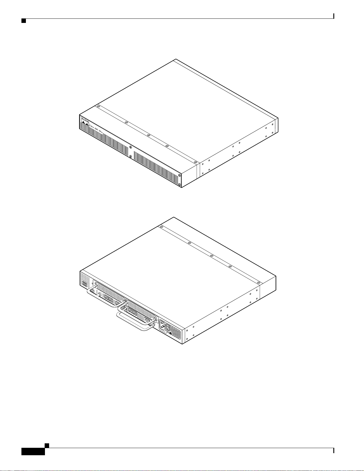
Figure 1-1 Cisco AS5350 Front Panel
3
35663
Figure 1-2 Cisco AS5350 Rear Panel
Dial Feature Cards (DFCs)
35665
1-2
The Dial Featu r e Ca rd (DF C ) is a 5.1 by 13 in ch PCI - ba sed int er fac e boar d tha t al lows o nlin e in s erti o n
and removal (OIR) of trunk ingress, and modem cards without rebooting or powering off the system.
The chassis includes one backplane slot which accepts a DFC carrier card. The DFC carrier card accepts
two DFCs, which allow OIR. The motherboard accepts one DFC in its own dedicated slot.
Cisco AS5350 Universal Ga teway Chassis Installation Guide
78-10754-03 0A
Page 19
Chapter1 Overview
Note For details on cards, in stal latio n, and trou blesh ooti ng, s ee the Cisco AS5350 Universal Gateway Card
Installation Guide. This document is a vail able on th e W orld W ide W eb and th e document ati on CD-R OM
that com es w ith y o ur u niver sal gateway. (See t he “Rela te d D ocumentati on” sect ion on pag e xi i.)
Power Supply
The power system is comprised of a single AC or DC power supply or a redundant AC or DC power
supply. Cooling is provided by two self-contained fans.
Note The Cisco AS5350 redundant power supply is supported in Cisco IOS Release 12.2(2)XB5 or later.
Each power module is capable of supplying a maximum DC load of 150 watts, and is composed of four
independent output voltages: 3 .3V, 5V, 12V, and -12V. AC input units have power factor correction, an d
low Total Harmonic Distortion. Power failures are reported through environm ental monitoring software.
Check th e power at your site to ensur e that yo u a re r ece ivin g “clean” power (free of spikes an d noise ).
Install a power conditioner if necessary.
Power Supply
Chassis Specificat ions
Table 1-1 Chassis Specifications
Description Specification
Dime n s io ns (H x W x D) 1.73 x 17.5 x 2 0.5 in . ( 4.39 x 44. 45 x 5 2. 07 cm )
Weight 22 lb maximum (10 kg)
Processor 250 MHz
Operati ng temperat ur e 32 to 1 04° F (0 to 40°C)
Operating humidity 5 to 95%, noncondensing
Noise level 55 dB
Input volt ag e, AC power supply
Current
Freq uency
Power factor
Input AC power
Input voltage, DC power supply
Maxim um input current
Input DCpower
WAN i nt er fac e o p tio n s T1 and E1 dial fe atu r e c ar ds
Serial in terfaces (f or back haul
WAN support)
LAN interfa ce options 2 Fast Ethernet 10/100BASE-T (RJ-45) ports
1
@ 3 ft (0.914 m)
100 to 240 VAC
2.0 to 1.0 A; dependent on load
50/60 Hz
0.80 to 0.90
140 to 170W; dependent on load
-48/ -6 0 Vdc, - 1 0%, +10% to leranc e
3 A (1 .5 -2.0 A t yp ical)
150 W (maximum)
2 serial line in terfa ces
2
; -10%, +6% tolerance
78-10754-03 0A
Cisco AS5350 Universal Gateway Chassis Installation Guide
1-3
Page 20

Chassis Specifications
Chapter1 Overview
Table 1-1 Chassis Specifications (cont inued)
Description Specification
Console and auxiliary ports Asynchronous serial (RJ-45)
Regulato ry co mp liance See the Regulatory Compliance and Safety
Infor mation docu m e nt that s h ip ped wi th y our
univ ersal g ate way . This document is a v ailabl e on
the World Wid e Web and th e documentat ion
CD-ROM that comes with your universal
gateway. (See the “Related Documentation”
section on page xii.)
1. dB = decibels.
2. VAC = volts alternating current.
1-4
Cisco AS5350 Universal Ga teway Chassis Installation Guide
78-10754-03 0A
Page 21

Preparing to Install the Cisco AS5350 Chassis
This chapter describes the tasks you must perform before you begin to install the Cisco AS5350 and
includes t h e f ol low in g sect io n s :
• Safet y R e c ommen dation s, p age 2- 1
• Required Tools and Equipment, page 2-3
• Preparing to Connect to a Network, page 2-3
Safety R ecommen dations
Any device that use s electricit y mu st be handle d caref ully ; follow thes e guidel ines to ensure ge nera l
safety:
• Keep the chas si s ar ea clear an d d ust-free du rin g an d af ter installat io n.
CHAPTER
2
• Put the removed chassis cover in a safe place.
• Keep tools away f rom wal k areas w here you and ot h er s co ul d fall o ver th em.
• Do not wear loose clothing that could get caught in the chassis. Fasten your tie or scarf and roll up
your sleeves.
• Wear safety glasses if you are working under any conditions that might be hazardous to your eyes.
• Do not pe rfo rm any action that cr eat es a p ot en tial hazard to pe op le or ma k es th e eq u ip m en t u nsa fe .
Warning
Ultimate disposal of this product should be handled according to all national laws and regulations.
T o see translations of the warnings that appear in the publication, refer to the Regulatory Compliance
and Safety Information document that accompanied this device.
Maintaining Safety with Electricity
Warning
Before working on equipment that is connected to power l ines, remove jewelry (including rings,
necklaces, and watches). Metal objects will heat up when connected to power and ground and can
cause serious burns or can weld the metal object to the terminals. T o see translations of the warnings
that appear in the publication, refer to the Regulatory Compliance and Safet y Information document
that accompanied this device.
78-10754-03 0A
Cisco AS5350 Universal Gateway Chassis Installation Guide
2-1
Page 22

Safety Recommendations
Chapter2 Preparing to Install the CiscoAS5350 Chassis
Follow these guidelines when you work on equipment powered by electricity.
• Locate the emergency power-OFF sw i tch f o r th e r oom in w hi ch y ou are working . Th en , if a n
electrical ac cid en t oc cu rs, yo u ca n act quick ly to t ur n O FF th e power.
• Before wor k in g on t he sy s tem , u np l ug t he power co r d .
• Disconnect all power before doing the following:
–
Insta lling or r emoving a ch a s sis
–
Working ne ar pow e r suppli es
Warning
Warning
When installing the unit, the ground connection must alway s be made fi rst and disconnected last. Do
not work alone if potentially hazardous conditions exist. To see translations of the warnings that
appear in this publication, refer to the Regulatory Compliance and Safety Information document that
accompanied this device.
• Never assume that power is disconnected from a circuit. Always check.
Read the installation instructions before you connect the system to its power source. To see
translations of the warnings that appear in the publication, refer to the Regulatory Compliance and
Safety Information docum ent that accompanied this device.
• Look carefully for possible hazards in your work area, such as moist floors, ungrounded power
extension cables, frayed power cords, and missing safety grounds.
• If an electrical acciden t occur s, pro ceed as follow s:
–
Use caution; do not become a victim yourself.
–
Turn OFF power to the system.
–
If possi ble, sen d anothe r person t o get medic al aid. Ot herwis e, asses s the condi tion of th e victi m
and then call fo r help .
–
Determine if the person needs rescue breathing or external cardiac compressions; then take
appropri ate act io n .
Warning
This product relies on the building’s installation for short-circuit (overcurrent) protection. Ensure that
a fuse or circuit breaker no larger than 120VAC, 15AU.S. (240 VAC, 10A international) is used on the
phase conductors (all current-carrying conduct ors). To see translations of the warnings that appear
in the publication, refer to the R egulatory Compliance and Safety Information document that
accompanied this device.
Preventi ng Electrostatic Disc harge Damage
Electr ostati c disc harge (ESD) can da mage equ ipment a nd impa ir ele ctric al cir cuitry. ESD dama ge occurs
when electronic components are imprope rly handled and can result in complete or intermittent failures.
Always follow ESD-prevention procedures when you remove and replace components. Ensure that the
chassis is electricall y co nn ected to ear th g r ou n d. Wear an ES D -pr eventive wr is t str ap , ensuring th at it
makes good skin contact. Connect the grounding clip to an unpainted surface of the chassis fra me to
Cisco AS5350 Universal Ga teway Chassis Installation Guide
2-2
78-10754-03 0A
Page 23

Chapter 2 Prep a rin g to Insta ll th e Cisc o AS 5 350 Ch ass is
safely ground unwanted ESD volt ages. To guard against ESD damage and shocks, the wrist strap and
cord must operate properly. If no wrist strap is available, ground yourself by touching the metal pa rt of
the chassis.
Caution For safety, periodically check the resistance value of the antistatic strap, which should be between 1 and
10 megohm (Mohm).
Required Tools and Equipment
The fo llow in g it em s are included with the univers al gateway:
• 19- and 24-inch rack-mount kits
• Rubbe r feet for deskto p ins talla tion
• RJ-45-to-DB-9 female DTE adapter (labeled TERMINAL)
• RJ-45-t o-DB-2 5 femal e DTE adapter (lab ele d TERMINAL)
• RJ-45-to-DB-25 male DCE adapter (labeled MODEM)
Required Tools and Equipment
• RJ-45-to-RJ-45 rollover console cable
• ESD-pr event ive wris t str ap
• Nylon cable tie
• Cable tie ho ld er
• Grounding lug
You might need the following equipment, which is not included:
• Straight-through RJ-45-to-RJ-45 cable for an Ethernet connection
• Up to two straight-through RJ-45-to-RJ-45 cables for T1 connections
• Up to tw o E1 ca bl es f o r E 1 co nn ec tio n s
• Ethernet hub or PC with a network interface card for Ethernet LAN connections
• PC runni ng t er min al emulation so f tw ar e f o r lo cal ad m in i str ative a cce s s
• Modem for remote administrative access
Preparing to Conne ct to a Network
When you set up your universal gateway, consider distance limitations and potential electromagnetic
interferen ce (EMI) as defined by th e Electro ni c I n du st ri es A ss o ci ati on (EIA) .
Warning
78-10754-03 0A
Hazardous network voltages are pres ent in WAN ports regardless of whether power to the router is
OFF or ON. To avoid electric shock, use caution when working near WAN ports. When detaching
cables, detach the end away from the router first. To see translations of the warnings that appear in
the publication, refer to the Regulatory Compliance and Safety Information document that
accompanied this device.
Cisco AS5350 Universal Gateway Chassis Installation Guide
2-3
Page 24

Preparing to Connect to a Network
Chapter2 Preparing to Install the CiscoAS5350 Chassis
Warning
The ISDN connection is regarded as a source of voltage that should be inaccessible to user contact.
Do not attempt to tamper with or open any public t elephone operator (PTO)-provided equipment or
connection hardware. Any hardwired connection (other than by a nonremovable,
connect-one-time-only plug) must be made only by PTO staff or s uitably trained engineers. To see
translations of the warnings that appear in the publication, refer to the Regulatory Compliance and
Safety Information docum ent that accompanied this device.
Ethernet Con nections
Two Fast Ethernet (FE) ports, RJ-45 ports, are located on the rear panel of the universal gateway: FE0
and FE1 (s ele ctable). To configure th e Et h er ne t p o rt s, r ef er t o the Cisco AS5350 and Cisco AS5400
Universal Gateway Software Config ur ation Guide. Both ports use unshielded twisted-pair (UTP) cable
and requir e Category 5 cab le. The m ax imu m segmen t distanc e i s 3 28 f eet ( 10 0 meters).
Note UTP cables l ook like t he cabl es use d fo r or dina ry tel epho ne s; however, UTP ca bles m eet cert ain
electrical standards that telephone cables do not. Cables are not included.
Console and Auxiliary Ports
The Cisco AS5350 includes an asynchrono us serial console port and an auxiliary port. The console and
auxiliar y po rts p rovi de access to th e u n iversa l g atewa y e it he r l o cal ly ( w ith a consol e t er m in al ) or
remotel y (w i th a m o dem). Th is s ect io n discu ss es i m p ortant cabling in fo r m at io n to co nsider b e for e
connecti ng a co nso le term in al (a n ASC I I ter minal or PC r un n in g ter minal em ulation sof tw are ) to the
console port, or modem to the auxiliary port.
Console Port
The Cisco AS5350 includes an EIA/TIA-232 asynchronous serial console port (RJ-45). Depending on
the cable an d the ada pt er us ed , th is port will appe ar as a data ter min al equip men t ( D TE ) or d at a
communications equipment (DCE) device at the end of the cable. Your universal gateway arrives with
cables and adapters to connect a console terminal (an ASCII terminal or PC running terminal emulation
software) to the co ns ol e p or t. To connect an A SCI I te rminal to th e console p o rt , u se the RJ-4 5 r o ll over
cable wit h th e f emale RJ -4 5 -t o-D B -2 5 ad ap ter ( l abe le d TERMINAL ).
To connec t a PC run ni ng t er min al emulati on s o ftw ar e t o t h e co n s ole p o rt , u s e th e R J- 45 r ol lover cab le
with the female RJ-45-to-DB-9 adapter (labeled TERMINAL). The default parameters for the console
port are 9600 baud, 8 data bits, no parity, and 2 stop bits. The console port does not support hardware
flow co ntro l.
For detailed infor m at io n ab ou t i n s tal li ng a co nso le term in al, s ee Ch ap t e r 3, “Installing the
Cisco AS5350.” See A p pendi x C, “Cabling Specifications,” for cable and port pinouts.
2-4
Cisco AS5350 Universal Ga teway Chassis Installation Guide
78-10754-03 0A
Page 25

Chapter 2 Prep a rin g to Insta ll th e Cisc o AS 5 350 Ch ass is
Auxiliary Port
The Cisco AS5350 includes an EIA/TIA-232 asynchronous serial auxiliary port (RJ-45) that supports
flow cont rol . Dep endi ng o n t he ca ble and th e adap ter us ed, t his por t wil l a ppea r as a DTE or DCE de vi ce
at the end o f the cab le. Yo ur u niversal gat eway a rrives wi th a ca bl e an d an a da pt er to con n ect a m o de m
to the au xi li ar y po r t. To connect a modem to th e auxili ar y por t, u s e th e R J -45 r o llove r cab le w it h th e
male RJ-45-to-DB-25 adapter (labeled MODEM).
For detailed infor mation ab ou t c on n ect in g devi ces to th e auxili ar y p o rt, s e e C h ap ter 3 , “Ins ta ll ing t he
Cisco AS5350.” See A p pendi x C, “Cabling Specifications,” for cable and port pinouts.
2T Seri al Ports
Two high speed 12-in-1 serial ports on the rear panel of the Cisco AS5350 provide backhaul WAN and
IP support.
The following types of serial interface standards (in DTE/DCE) are supported:
• EIA/TIA-232
• EIA/TIA-449
Preparing to Connect to a Network
Alarm Port
BITS Port
• EIA/TIA-530
• EIA/TIA-530A
• EIA/TIA-X.21
• ITU-T V. 35
Each interface supports up to 8 Mbps.
The three pins on the alarm port are connected to the output of a relay. This relay is controlled by system
software . To configure the Alarm port , refer to the Cisco AS5350 and Cisco AS5400 Universal Gateway
Softw are Config ur a tion Guide. This document is available on CCO and the documentation CD-ROM
that com es w ith y o ur u niver sal gateway. (See t he “Rela te d D ocumentati on” sect io n on pag e xi i. ) With
the alarm ports c on n ect ed an d co nfigu r ed , C isc o I O S so f tw ar e p olls every on e s eco n d to d ete ct the
failure events t hat ar e co nfigu r ed an d tu rns O N th e alarm wh en i t d et ect s any fa il ure event. See
Appendix C, “Cabling Specific ations,” for pino uts an d cab l e sp eci fica ti on s.
The BITS p or t is a coaxia l i nt er fac e t ha t p rovi d es ext er n al s ynch r on iz ed cl oc ki ng t hro ug h a Timin g
Signal Ge nerator (T S G). To confi g u r e t h e B I T S port, r e f er to the Cisco AS5350 and Cisco AS5400
Universal Gateway Software Configu ration Guide. This document is available on CCO and the
docume nt ati on C D - ROM th at comes w i th y ou r u nivers al gat eway. (See th e “Related D o cu m en tation”
section on page xii.) See Appendix C, “C ab ling Specification s,” for pinouts an d cable specificatio ns.
78-10754-03 0A
Cisco AS5350 Universal Gateway Chassis Installation Guide
2-5
Page 26
Preparing to Connect to a Network
Power Supply C onsiderations
Check th e power at your site to ensur e that yo u a re r ece ivin g “clean” power (free of spikes an d noise ).
Install a power conditioner if necessary.
Chapter2 Preparing to Install the CiscoAS5350 Chassis
Warning
Warning
The device is designed to work with TN power systems. To s ee translati ons of the warnings that
appear in the publication, refer to the Regulatory Compliance and S afety I nformation document that
accompanied this device.
This product relies on the building’s installation for short-circuit (overcurrent) protection. Ensure that
a fuse or circuit breaker no larger than 120VAC, 15AU.S. (240 VAC, 10A international) is used on the
phase conductors (all current-carrying conduct ors). To see translations of the warnings that appear
in the publication, refer to the R egulatory Compliance and Safety Information document that
accompanied this device.
The universal ga teway AC power supply includes the following features:
• Full range operation—100 to 240 VAC.
• All unit s in cl ud e a 6-foo t ( 1 .8 -m ) e lectrical p ower cord . ( A lab el n ear th e p ow er in let indica tes t he
correct voltag e, frequ ency, and current draw for the unit .)
Note The redu n da nt AC powe r s up p ly h a s a pow er co r d w ith a s p eci al co nn ector.
The universal ga teway DC power supply includes the following features:
• 150 W output
• Dual input c onnections for power source redundancy
• Removable DC connector (A label near the power inlets indicates the correct voltage, current draw,
and pow er dissi pa tion for the u ni t. )
2-6
• Double-hole grounding lug for reliable grounding to the chassis
Cisco AS5350 Universal Ga teway Chassis Installation Guide
78-10754-03 0A
Page 27

CHAPTER
3
Installing the Cisco AS5350
This cha pt er gu id es you thro ugh t he i nst alla t ion o f t he C isc o AS535 0 u ni v er sal g at e wa y an d i ncl udes t he
followi ng sec t ions:
• Setting Up the Chassis, page 3-2
• Connecting to the Network, page 3-6
• Connecting to the Console and Auxiliary Ports, page 3-11
• Connecting a Signal Generator to the BITS Port, page 3-13
• Connecting an Alarm to the Alarm Port, page 3-14
• Supplying Power, page 3-15
• Where to Go Next, page 3-19
Warning
Warning
Warning
Only trained and qualified personnel should be allowed to install or replace this equipment. To see
translations of the warnings that appear in the publication, refer to the Regulatory Compliance and
Safety Information docum ent that accompanied this device.
This equipment is intended to be grounded. Ensure that the host is connected to earth ground during
normal use. To see translations of the warnings that appear in the publication, refer to the Regulatory
Compliance and Safety Information document that accompanied this device.
Incorrect connection of this or connected equipment to the general purpose out let could result in a
hazardous situation. To see translations of the warnings that appear in the publication, refer to the
Regulatory Compliance and Safety Information document that accompanied this device.
78-10754-03 0A
Cisco AS5350 Universal Gateway Chassis Installation Guide
3-1
Page 28

Setting Up t he Chassis
Setting Up the Chassis
You can s e t t he ch as si s o n a d esk top or install it i n a r ack . Use the procedure in t hi s se c ti on th at b est
meets the needs of your network:
• Setting the Chassis on a Desktop
• Rack-Mounting the Cha ssis
Chapter3 Installing the Cisco AS5350
Warning
Warning
When installing the unit, the ground connection must always be made first and disconnected last. To
see translations of the warnings that appear in the publication, refer to the Regulatory Compliance
and Safety Information document that accompanied this device.
This unit is intended for installation in restrict ed access areas. A restricted access area is where
access can only be gained by service personnel through the use of a special tool , lock and key, or
other means of security, and is controlled by the authority responsible for the location. To see
translations of the warnings that appear in the publication, refer to the Regulatory C ompliance and
Safety Information docum ent that accompanied this device.
Setting the Chassis on a Desktop
The locati on o f th e ch as sis is ex tr em e ly important for pro p er o pe ra tio n . Eq u ip m en t pl ace d to o clo s e
togethe r, inadequat e v e nt ilat i on, an d ina c cess ibl e pane ls c an c aus e m alf unc ti ons and s hutd o wn s, a nd c an
make ma in ten ance d ifficult . The fol low in g i n fo r m at io n will help you p la n the location of th e ch as sis :
• Plan for acc es s t o bo th f r ont an d r e ar pa ne ls o f th e ch ass is.
• Ensure that the room where the chassis operates has adequate ventilation. Remember that electrical
equipment generates heat. Ambient air temperature may not cool equipment to acceptable operating
temperatures without adequate ventilation.
Attaching the Rubber Feet
To att ach t he r ub b er f eet to the chass i s, follow th i s pr o ced u re :
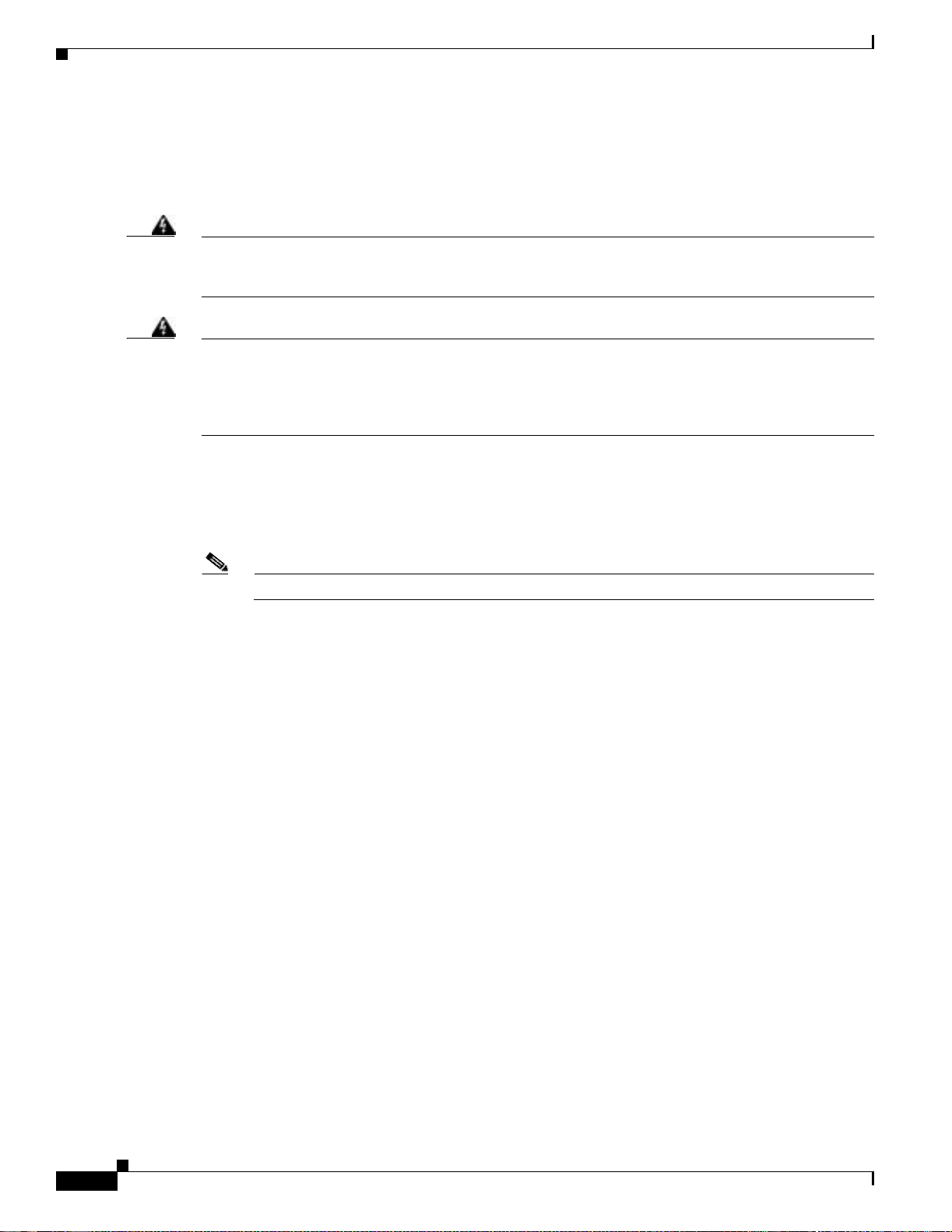
Step 1 Carefull y tu rn th e ch as si s over s o yo u can see the f o ur sm al l d ep re s sio n s m ad e f or attaching th e r u bber
feet. (See Figure 3-1.) The rubber feet are included in the accessory kit that shipped with your universal
gateway.
Step 2 Remov e the wax paper from the bottom of each rubber foot and pres s the foot into the small depression
on the bottom of the chassis. (See Figure 3-1.)
Cisco AS5350 Universal Ga teway Chassis Installation Guide
3-2
78-10754-03 0A
Page 29
Chapter3 Installing the Cisc oAS5350
Figure 3-1 Attaching the Rubber Feet
Setting Up the Chassis
Rack-Mount i ng t he Chassis
This section describes how to rack-moun t th e chassis. T he u niversal gateway arrives with 19-inch
rack-mount brackets and larger brackets for use with a 23- or 24-inch rack (See Figure 3-2).
The following information will help you plan your equipment rack configuration:
• Enclosed racks must have adequate ventilation. Ensure that the rack is not congested, because each
unit gen er at es h eat. An en cl o sed ra ck s h ould h ave lo u ver ed si des and a f an to p rovid e coolin g air.
Heat generated by equipment near the bottom of the rack can be drawn upward into the intake ports
of the equipment above.
• When mo un ti ng a ch as si s in a n op en r ack , en sur e t h at th e r ack frame d oe s n ot block the i nt ake o r
exhaust ports. If the chassis is installed on slides, check the position of the chassis when it is seated
in the ra ck .
• Baffles can isolate exhaust air from intake air, which also helps to draw cooling air through the
chassis. The best placeme nt of the baffles depends on the airf low patterns in the rack, which can be
found by experimenting with different configurations.
37208
Universal gateway
chassis bottom
Warning
78-10754-03 0A
Before working on a chassis or working near power supplies, unplug the power cord on AC units;
disconnect the power at the circuit breaker on DC units. To see translations of the warnings that
appear in the publication, refer to the Regulatory Compliance and S afety Information document that
accompanied this device.
Cisco AS5350 Universal Gateway Chassis Installation Guide
3-3
Page 30
Setting Up t he Chassis
Required Tools and Equipment
You need the following tools and equipment to rack-mount the chassis:
• Number 2 Phillips screwdriver (not included)
• Medium flat-blade screwdriver (not include d)
• Screws for attach ing the chassis to the rack (not inclu ded)
• Standard rack-mount brackets (included)
• Screws for att ach in g th e bracket s to t he chassi s ( in clu d ed )
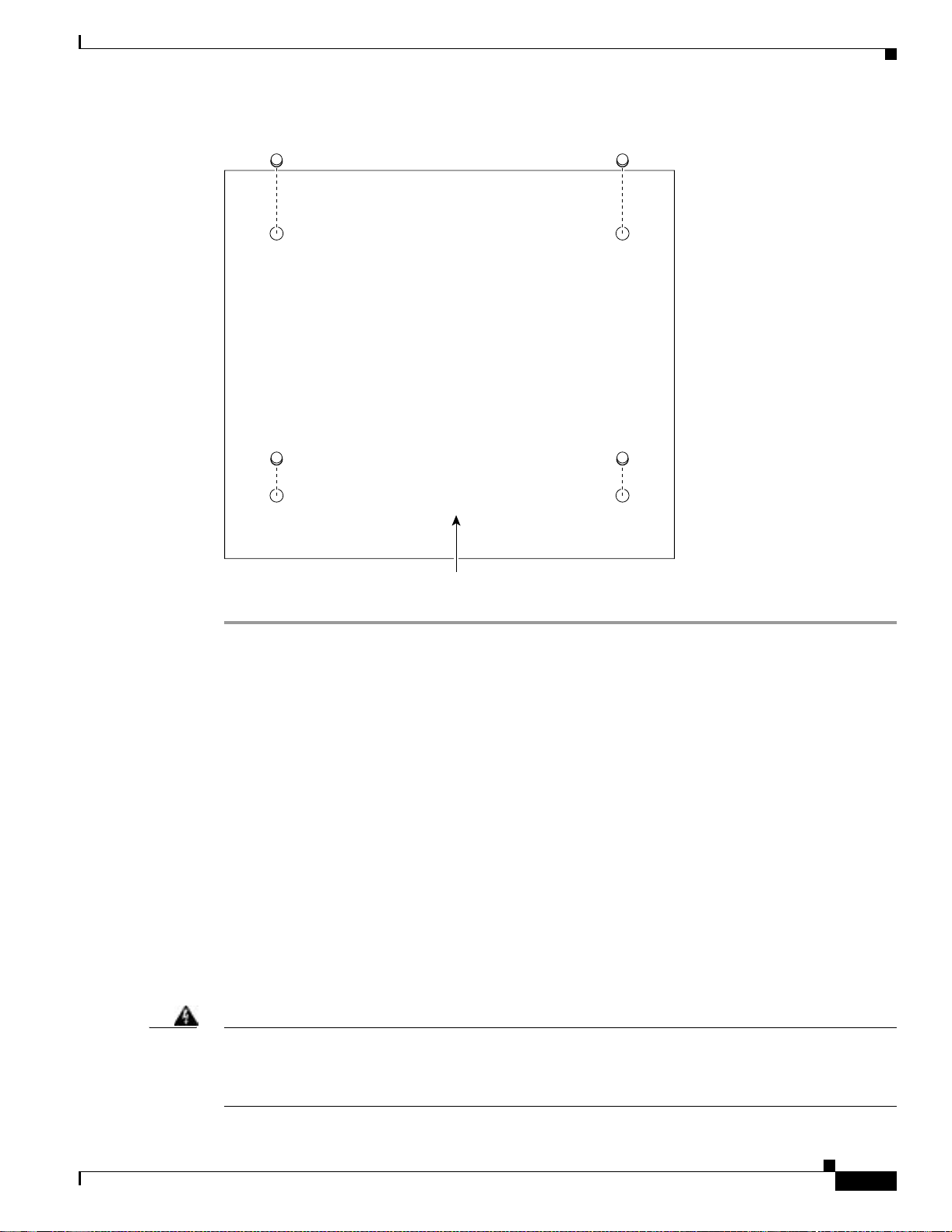
Figure 3-2 Standard Rack-Mount Brackets
Chapter3 Installing the Cisco AS5350
Attaching the Brackets
To attach t he mountin g brackets to th e chassis , f ol low th is procedu re :
Step 1 Set the c ha s sis o n a fl at sur fa ce. (See Figu re 3-3.)
Note The chassis may be installed with either the front or rear panel facing forward.
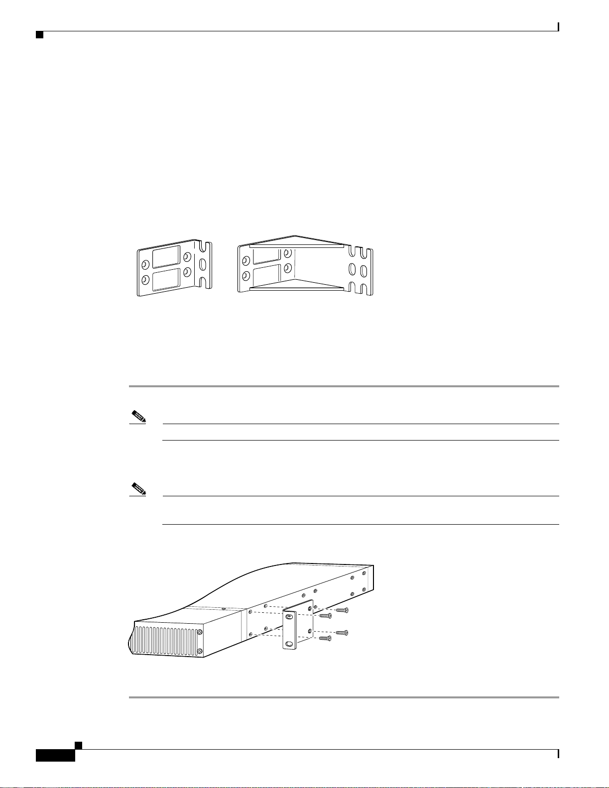
Step 2 Attach the standard 19 or 23-inch rack brackets to the sides of the chassis. Use the screws provided with
the mounting brackets. (See Figure 3-3.)
Note There are three sets of mounting holes on the sides of the chassis. Attach the brackets for front,
Figure 3-3 Standard Bracket Installation—Front Panel Forward
Bracket for 23-inch rackBracket for 19-inch rack
rear, or middle mounting.
36012
35669
3-4
Note: The second bracket attaches to the other side of the chassis.
The chassis can also be installed with the rear panel forward.
Cisco AS5350 Universal Ga teway Chassis Installation Guide
78-10754-03 0A
Page 31

Chapter3 Installing the Cisc oAS5350
Installing in a Rack
Caution Do not use the h a n d les on t he d ial f eat ur e car d s to a s sist in liftin g th e ch as sis.
To instal l th e ch as sis into th e e qu ip m en t ra ck , f o llow this pro ce du r e:
Step 1 With the mounting brackets attached to the chassis, support the chassis and align the holes in the brackets
with the s cr ew ho le s in t he rack. ( See Figu re 3-4.)
Step 2 Attach th e chassis to th e rack w it h th e screws you h ave pr ov id ed . ( See Figure 3-4.)
Figure 3-4 At taching the Chassis to a 19-Inch Rac k— R ear Panel F orward
Setting Up the Chassis
35659
Note: The second bracket attaches to the rack at the other side
of the chassis. The chassis can also be installed with the
front panel forward.
Connec t ing the Chassis Ground
You must connect t he chass is to a re liab le ea rth gr oun d usi ng the gro und lug (pro vid ed ) and s ize AWG 6
(13 mm2) wire.
To attach the chass i s g ro u nd, t ake th e fo ll owing st eps:
Step 1 Strip one end of the ground wire to expose approximately 0.75 in. (20 m m) of conductor.
Step 2 Crimp the ground wire to the ground lug, using a crimp tool of the appropriate size.
Step 3 Attach the ground lug to the chassis. (See Figure 3-5 or Figure 3-6.) Use a medium flat-blade
screwdriver and the screws supplied with the ground lug. Tighte n the scre ws to a torque of 8 to 10 in-lb
(0.9 to 1.1 N - m) .
Step 4 Connect the other end of the ground wire to a suitable grounding point at your site.
78-10754-03 0A
Cisco AS5350 Universal Gateway Chassis Installation Guide
3-5
Page 32

Connecting to the Network
Figure 3-5 Cisco AS5350 Ground Lug Attachment
Chapter3 Installing the Cisco AS5350
Ground lug
attachment
Figure 3-6 Cisco AS5400 Ground Lug Attachment
Connecting to the Network
82735
82734
Ground lug
attachment
3-6
This sec tion de scrib es ho w to conne ct the Cisco AS5350 to your netw ork. The cables requir ed to co nnect
the universal gateway to a network are not provided. For ordering information, contact customer service.
See the “Obt ain in g Technical A ss ist an ce” section on page xiv, or see Appendix C, “Cabling
Specificat io n s ,” for cable and port pinouts.
Warning
T o avoid electric shock, do not connect safety ext ra-low voltage (SELV) circuits to telephone-network
voltage (TNV) circuits. LAN ports contain SELV circuits, and WAN ports contain TNV circuits. Some
LAN and WAN ports use both RJ-45 connectors. Use caution when connecting cables. To see
translations of the warnings that appear in the publication, refer to the Regulatory C ompliance and
Safety Information docum ent that accompanied this device.
Warning
Do not work on the sy stem or connect or disconnect cables during periods of lightning activity. To see
translations of the warnings that appear in the publication, refer to the Regulatory Compliance and
Safety Information docum ent that accompanied this device.
Cisco AS5350 Universal Ga teway Chassis Installation Guide
78-10754-03 0A
Page 33

Chapter3 Installing the Cisc oAS5350
Caution If the universal gateway is configured with fewer than three DFCs, make sure that a blank slot cover is
insta lle d over ea ch open slot t o e ns u r e p r op e r a i r fl ow.
Note The Cisco AS5350 arrives with all carrier cards and DFCs already installed, unless you order a card
separat ely a s a sp ar e. Refer to th e Cisco AS5350 Universal Gateway Card Installation Guide for card
installation instructions. This document is available on Cisco.com and the documentation CD-ROM that
comes wi th y our univers al gateway. (See the “Obtaining Documentation” sectio n on page xiii.)
Connecti ng t o an Ethernet Network
Connect an Cisco AS5350 Fast Ethernet port to an Ethernet hub using a straight-through,
RJ-45- to-R J-45, Et hernet cabl e . (See F i gure 3 -7 . )
Figure 3-7 Connecting to an Ethernet Hub (10/100BASE-T Show n)
Connecting to the Network
10/100BASE-T port
(RJ-45)
Connecti ng t o a WAN
Warning
Warning
To reduce the risk of fire, use only No. 26 AWG or larger telecommunication line cord. To see
translations of the warnings that appear in the publication, refer to the Regulatory Compliance and
Safety Information docum ent that accompanied this device.
This equipment is to be installed and mai ntained by service personnel only as defined by A S/NZS 3260
Clause 1.2.14.3 Service Personnel. To see translations of the warnings that appear in the publication,
refer to the Regulatory Compliance and Safety Information document that accompanied this device.
FE1
Straight-through
Ethernet cable
Ethernet hub
8
7
1
35670
78-10754-03 0A
Cisco AS5350 Universal Gateway Chassis Installation Guide
3-7
Page 34

Connecting to the Network
Chapter3 Installing the Cisco AS5350
Warning
Warning
Hazardous network voltages are pres ent in WAN ports regardless of whether power to the router is
OFF or ON. To avoid electric shock, use caution when working near WAN ports. When detaching
cables, detach the end away from the router first. To see translations of the warnings that appear in
the publication, refer to the Regulatory Compliance and Safety Information document that
accompanied this device.
The telecommunications lines must be disconnected 1) before unplugging the main power connector
and/or 2) while the housing is open. To see translations of the warnings that appear in the publication,
refer to the Regulatory Compliance and Safety Information document that accompanied this device.
You can con ne ct the Cis c o AS535 0 t o a WAN in the f o ll owi ng w ays:
• Connect each T1/PRI port to an RJ-45 jack with a straight-through RJ-45 to RJ-45 cable. (See
Figure 3-8 and Figure 3-9.)
Figure 3-8 Connecting a 2-Port or 4-Port DFC to an RJ-45 (T1) Jack
3-8
Straight-through
RJ-45-to-RJ-45 cable
Cisco AS5350 Universal Ga teway Chassis Installation Guide
RJ-45 jack
35672
78-10754-03 0A
Page 35

Chapter3 Installing the Cisc oAS5350
Figure 3-9 Connecting an 8-Port DFC to a RJ-45 (T1) Jac k
0
1
2
P
P
P
P
T1/E1 8 PRI
connector
Connecting to the Network
56057
3
4
5
6
P
7
P
P
P
Straight-through
RJ-45-to-RJ-45 cable
RJ-45 jack
Note Use software commands to choose a specific port and the line termination on that port. For information
on softwar e comman ds, see the Cisco AS5350 and Cisco AS5400 Universal Gateway Software
Conf igur ation Gui de. This document is available on the Cisco.com and the documentation CD-ROM that
comes wi th y our univers al gateway. (See the “Obtaining Documentation” sectio n on page xiii.) If you
choose a port with 75- ohm inp ut impedanc e, u s e an RJ- 45 - to-75- ohm coaxial c a b le adapt e r an d plug it
into that port .
• Connect each E1/PRI port to an RJ-45 jack with a straight-through RJ-45 to RJ-45 cable. (See
Figure 3-10 and Figure 3-11.)
Warning
The E1 interface card may only be installed in an ACA-permitted customer equipment or a Data
T erm in al Equipment (DT E) that is ex empted from ACA ’s permit requirements. The customer equipment
must only be housed in a cabinet that has screw-down lids to stop user access to overvoltages on the
customer equipment. The customer equipment has circuitry that may have telecommunications
network voltages on them. T o see translations of the warnings that appear in the publication, refer to
the Regulatory Compliance and Safety Information document that accompanied this device.
78-10754-03 0A
Cisco AS5350 Universal Gateway Chassis Installation Guide
3-9
Page 36

Connecting to the Network
Figure 3-10 Connecting a 2-Port or 4-Port DFC to an RJ-45 Jack
Chapter3 Installing the Cisco AS5350
35673
RJ-45 jack
E1 cable
Figure 3-11 Connecting an 8-Port DFC to an RJ-45 Jack
0
1
2
P
T1/E1 8 PRI
connector
E1 cable
3
P
4
P
5
P
6
P
7
P
P
P
56058
RJ-45 jack
3-10
Cisco AS5350 Universal Ga teway Chassis Installation Guide
78-10754-03 0A
Page 37

Chapter3 Installing the Cisc oAS5350
• Connect a synchronous serial port to a modem or a CSU/DSU with a serial transition cable. (See
Figure 3-12.)
Figure 3-12 Connecting to a CSU/DSU
Synchronous serial
port (DB-26)
Connecting to the Console and Auxiliary Ports
35675
Internet
Serial
transition
cable
EIA/TIA-232, EIA/TIA-449, EIA/TIA-530A,
EIA/TIA-530, V.35, or X.21 connector
CSU/DSU or
other DCE or DTE
Connecting to the Console and Auxiliar y Ports
Use the console terminal for local administrative access to the universal gateway. You can only connect
a terminal to the console port. Y ou can use the auxiliary port to connect a terminal or a modem for remote
access to th e u n iversal g ateway.
Connecting to the Console Port
To conn ec t a termi n al ( an ASC I I ter mi nal or a P C r u nn in g termin al em u la tio n s o ft wa re) to th e c on s o le
port on the Cisco AS5350, follow this procedure:
Step 1 Connect the terminal to the consol e port using an RJ-45 rollover cable and an RJ-45-to-DB-25 or
RJ-45-t o-D B- 9 ad ap te r. The adap ters provid ed ar e lab el ed TERMINAL. Th e a da pt er s an d th e rollover
cable are in clu d e d in t he ac ces so r y ki t t ha t c omes with the un iversal g a teway. (See Fi gu re 3-13.)
78-10754-03 0A
Note For addit i onal inform ati on on rollo v er cabl e pinou ts, see Appe nd ix C, “Cabling Specifications.”
Step 2 Configure your terminal or PC terminal emulation software for 9600 baud, 8 data bits, no parity, and
2 stop bi ts.
Step 3 Configure the console port. See the Cisco AS5350 and Cisco AS5400 Universal Gateway Software
Configuration Guide. This document is available on the World Wide Web and the documentation
CD-ROM that comes with your universal gateway. (See the “Obta inin g Doc ume ntat ion” section on
page x iii.)
Cisco AS5350 Universal Gateway Chassis Installation Guide
3-11
Page 38

Connecting to the Consol e and Auxiliary Ports
Figure 3-13 Connecting the Console Terminal
Console port
(RJ-45)
RJ-45-to-RJ-45
rollover cable
Chapter3 Installing the Cisco AS5350
35676
PC (laptop)
RJ-45
Connecting a Mode m to th e Auxiliary Port
To connect a mo de m t o t he au x il iar y p or t, fol low th is p r oc ed ur e:
Step 1 Connect a modem to the auxiliary port on the Cisco AS5350 using an RJ-45 rollover cable with an
RJ-45-t o-D B- 2 5 ad ap ter. The ad ap ter p r ovide d i s l ab ele d M O D EM . Th e ad ap t er an d th e r o llove r cab le
are inclu de d in th e accessory k it th at co m e s w it h th e u niver sal ga teway.(See F igure 3-14 .)
Note Make sure that your modem and the auxiliary port on the Cisco AS5350 are configured for the
same transmission speed (38400 baud is typical) and hardware flow control with Data Carrier
Detect (DCD) and Dat a Terminal Ready (DTR) operations.
3-12
Cisco AS5350 Universal Ga teway Chassis Installation Guide
78-10754-03 0A
Page 39

Chapter3 Installing the Cisc oAS5350
Figure 3-14 Connecting a Modem to the Auxiliary Port
Connecting a Signal Generator to the BITS Port
RJ-45-to-RJ-45
rollover cable
Auxiliary port
(RJ-45)
Modem
RJ-45-to-DB-25 adapter
(labeled MODEM)
Connecting a Sign al Generat or to the BI TS Port
Use a coax ia l ca ble t o conn ec t a T i min g Si gna l Gen er ator (TS G) to th e BIT S por t. T he BIT S po rt i s use d
for external clocking. (See Figure 3-15.)
Figure 3-15 Connecting to the BITS Port
35841
35677
78-10754-03 0A
To timing signal
generator
Coaxial cable
BITS port
connector
Cisco AS5350 Universal Gateway Chassis Installation Guide
3-13
Page 40

Connecting an Alarm to the Alarm Port
Connecting an Alar m to the Alarm Port
To connect an alar m device to the alarm port, foll ow this proc edure:
Note The alarm connecto r i s a 3-wire co nn ec to r th at pl ug s i nt o a r ec ep tacle in th e re ar of the chassis. The
connec to r is p r ovi d e d in th e accessory k it th at ships w it h th e Cisco AS5350 .
Step 1 Insert the three pin alarm port connector (included in the accessory kit) into the alarm port terminal
block.
Step 2 Strip a m in imum 1/4 in . ( 0 .6 25 cm) off the wi r e i nsu la tio n to con n ect th e s tr an de d wi re s t o t h e al ar m
connector. The maximum insulation strip length is 0.31 in. (0.78 cm).
Note Connec t t he al ar m p ort on ly t o a s a fe ty ex tr a- lo w v o lta ge ( S ELV) source usi n g 2 2 AWG, or
thicker, copper wire. SELV ratings are maximum 30 Volts AC (RMS), maximum 60 Volts DC,
and maximum 50 VA power. The alarm port is rated for 2.0 Amp maximum current.
Chapter3 Installing the Cisco AS5350
Step 3 Secure t he w ires to th e alarm co nnector w ith t he s crews o n th e co nn ec to r. See Ap p en di x C, “Cabling
Specificat io n s ,” for alarm port pinouts.
Caution The maximum tightening to rque on the screws is 7 in.-lb (0.79 N-m).
Step 4 Attach tw o cab l e t ies to th e chassis an d c on n ect th e wires t o th e c a b le t ie s. ( S ee F ig ure 3-16. )
Step 5 Attach th e alarm w ires to th e alarm device.
Figure 3-16 Connecting to the Alarm Port
To alarm device
Alarm port
connector
Cable ties
#1#2#3
35967
3-14
Cisco AS5350 Universal Ga teway Chassis Installation Guide
78-10754-03 0A
Page 41

Chapter3 Installing the Cisc oAS5350
Supplying Power
The power system comprises an AC or DC power supply or a redundant AC or DC power supply, with
internal cooling provided by two self-contained fans.
Note The redundant power supply is supported in Cisco IOS Release 12.2(2)XB5 or later releases.
Each power module is capable of supplying a maximum DC load of 150 watts, and is composed of four
independent output voltages: 3 .3V, 5V, 12V, and -12V. AC input units have power factor correction, an d
low Total Harmonic Distortion. Power failures are reported through environm ental monitoring software.
Check th e power at your site to ensur e that yo u a re r ece ivin g “clean” power (free of spikes an d noise ).
Install a power conditioner if necessary.
The universal ga teway AC power supply includes the following features:
• Full range operation—100 to 240 VAC.
• All AC units i nc lu de a 6 - f oot (1.8-m ete r) electric al power cor d (A l abel near t he power i nl ets
indicates th e c or r e ct voltage, frequ e n cy, cur r ent draw, and pow er d i ss i pation f or t he uni t.)
Supplying Pow er
Note The redundant AC power supply has a non-standard connector. Use the electrical power cord that
came with your universal gateway.
The universal ga teway DC power supply includes the following features:
• 150 W output
• Dual input c onnections for power source redundancy
• Removable DC connector (A label near the power inlets indicates the correct voltage, current draw,
and pow er dissi pa tion for the u ni t. )
• Double-hole grounding lug for reliable grounding to the chassis
Follow thi s p ro c e du r e t o connect power to the univers a l g a t eway:
Step 1 Connect one end of the AC power cord to the power connector on the rear panel of the Cisco AS5350 (See
Figure 3-17 or Figure 3-18.) Or , if you a re us ing a DC -po we red u ni t, re fer to Fi gur e 3-19 or Figure 3-20,
and comp let e S t ep a t hro u gh Step e.
Step 2 Connect the other end of the AC power cord to the power outlet.
Warning
This product relies on the building’s installation for short-circuit (overcurrent) protection. Ensure that
a fuse or circuit breaker no larger than 120 VAC, 15A U.S. (240 VAC, 10A international) is used on the
phase conductors (all current-carrying conduct ors). To see translations of the warnings that appear
in the publication, refer to the R egulatory Compliance and Safety Information document that
accompanied this device.
Warning
78-10754-03 0A
The device is designed to work with TN power systems. To see translations of the warnings that appear in
the publication, refer to the Regulatory Com pliance and Safety Information docu ment that accom panied this
device.
Cisco AS5350 Universal Gateway Chassis Installation Guide
3-15
Page 42

Supplying Power
Chapter3 Installing the Cisco AS5350
Warning
The plug-socket combination must be accessible at all times because it serves as the main
disconnecting device.To see translations of the warnings that appear in the publication, refer to the
Regulatory Compliance and Safety Information document that accompanied this device.
Figure 3-17 Connecting the AC Power Cord
35678
Power switch
Figure 3-18 Connecting the AC Power Cord to the Redundant Power Supply
Warning
82079
Power cables
Before performing any of the following procedures, ensure that power is removed from the DC circuit.
To ensure that all power is OFF, locate the circuit breaker on the panel board that services the DC
circuit, switch the circuit breaker to the OFF position, and tape t he s witch handle of the ci rcuit
breaker in the OFF position. To see translations of the warnings that appear in this publication, refer
to the Regulatory Compliance and Safety Information document that accompanied this device.
3-16
Cisco AS5350 Universal Ga teway Chassis Installation Guide
78-10754-03 0A
Page 43

Chapter3 Installing the Cisc oAS5350
Supplying Pow er
Warning
The illustration shows the DC power supply terminal block. Wire the DC power supply using the
appropriate wire terminations at th e wiring end, as illustrated. The proper wiring sequence is ground
to ground, return to return, and negative to negative. Not e that the ground wire should al ways be
connected first and disconnected last. To see translations of the warnings that appear in this
publication, refer to the Regulatory Compliance and Safety Information document that accompanied
this device.
Figure 3-19 DC Power Suppl y Connections—Single Power Supply
Power switch
To DC source
DC connector
56022
Source A - NEG
Source A - RTN
Ground
Source B - RTN
Source B - NEG
Caution Do not overtorque the terminal block contact screws. The rec ommended torque is 4.5 lb-in (0.50 N-m).
78-10754-03 0A
Cisco AS5350 Universal Gateway Chassis Installation Guide
3-17
Page 44

Supplying Power
Chapter3 Installing the Cisco AS5350
Figure 3-20 DC Power Suppl y Connections—Redundant Power Supply
To DC source
DC connector
A- A+
Source A - NEG
Source A - RTN
Note This pro duc t is int e nded for in sta lla t ion i n re st rict ed a cce ss are as and i s a ppr o ved for conn ec tio n
B- B+
Ground
Source B - RTN
Source B - NEG
Power switch
82637
using 12 or 14 AWG copper conductors only. The installation must comply with all applicable
codes.
3-18
Note If you are installing a redundant power supply, you should attach appropriate sized spade
terminals to the stripped ends of the ground and input wires.
a. Strip off a quarter of an inch (1/4 in. [0.625 cm]) of insulation on the safety ground, +48 VDC, and
-48 VDC input wires.
b. Insert the safety ground (green wire) into the DC connector ground connector and tighten the
locking screws. Ensure that no bare wire is exposed.
c. Inser t the 48 VDC Return wire s into t he DC c o nnector po s it ive c o nnectors (+) an d tigh t en the
locking screws. Ensure that no bare wire is exposed.
d. In se rt the -4 8 V DC w ires into t he D C connec to r neg ative c on n ect or s ( - ) an d t ighten the lo ck in g
screws. Ensure that no bare wire is exposed.
e. Make sure that the p ow er su pp ly w ir es ar e s e cu re d to cable st ra in -rel ief clam ps w ith cable tie s .
Cisco AS5350 Universal Ga teway Chassis Installation Guide
78-10754-03 0A
Page 45

Chapter3 Installing the Cisc oAS5350
Where to Go Next
Warning
Step 3 Power on the un ivers al gat eway.
After wiring the DC power supply, remove the tape from the circuit breaker switch handle and
reinstate power by moving the handle of the circuit breaker to the ON position. T o see translations of
the warnings that appear in this publication, refer to the Regulatory Compliance and Safety
Information document that accompanied this device.
The internal power supply fan should power on.
Where to Go Next
When you po we r ON the Ci sco AS5350 for th e f ir st t ime , me ssa ges will be gin to ap pea r on your c onso le
screen. Refer to the Cisco AS5350 a nd Ci sc o AS5400 Univer sal Ga te way Sof tware Configur a tion Guid e
for configuration instructions. This document is available on the World Wide Web and the
docume ntation CD -ROM th at co m es with you r Cisco A S5 35 0 . ( S ee th e “Obta in i ng D o cu m en tation”
section on page xiii.)
The rem ain in g ch ap te rs of t hi s g ui de in cl ud e referenc e m a ter i al for rep lac in g s pa re pa r ts,
troubleshooting, a nd creating your own cables:
• Chapter 4, “Troubleshooting”
• Appendix A, “Repl a ci ng Mem or y Comp onent s”
• Appendix B, “Replacing the Power Supply”
• Appendix C, “Cabling Specific ations”
78-10754-03 0A
Cisco AS5350 Universal Gateway Chassis Installation Guide
3-19
Page 46

Where to Go Next
Chapter3 Installing the Cisco AS5350
3-20
Cisco AS5350 Universal Ga teway Chassis Installation Guide
78-10754-03 0A
Page 47

LEDs
CHAPTER
4
Troubleshooting
This chapter describes troubleshooting te chniques for the Cisco AS5350. The chapter contains the
followi ng sec t ions:
• LEDs, page 4 -1
• Monit or ing Envir o nment, page 4- 3
• Troubleshooting Network Interfaces, page 4-6
• Replac i ng the Fa n Tray, pag e 4-6
• Gettin g H e lp , page 4- 1 2
The LEDs indicate the current operating condition of the Cisco AS5350. Y ou can observe the LEDs, note
any fault condition that the product is encountering, and then contact your system administrator or a
customer s e rv ic e r ep r esen tative (see th e “Obtain ing Technical Assistance” section on pa ge xiv), if
necessary. Refer to Figure 4-1 for a diagram illu strating the rear panel LEDs and Table 4-1 for a
description of the LEDs.
78-10754-03 0A
For information about LEDs and troubleshooting on Cisco AS5350 dial feature cards, see the
Cisco AS5350 Universal Gateway Card Installation Guide. This document is available on the World
Wid e W eb and the document ation CD-R OM th at come s with y our uni ve rsal g ate way . (See th e “Obtaining
Documentation” section on page xiii.)
Cisco AS5350 Universal Gateway Chassis Installation Guide
4-1
Page 48

LEDs
Chapter4 Troubleshooting
Figure 4-1 Rear Panel LEDs
T0
BITS
T1
Table 4-1 Chassis LEDs
ACTIVITY (ACT)
LNK
ACTIVITY (ACT)
BOARD OK
LED
LNK
35679
Function LED State Description
Alarm Alarm On An alarm er ror i s d et ect ed .
Fast Ethernet Activity (ACT) Flickering The Fast Ethernet LAN connection
is tran sm i tting and r e c eivin g data
norma lly.
Off The Fast Ethernet LAN connection
is not tra nsmit ting or recei ving da ta.
Link (LNK) On Fast Ethernet cable is connected
properly.
Off The Fast Ethernet port is not
connected.
Console /Auxiliar y Acti vity (ACT ) Flickeri ng The console or auxili ary connec tion
is tran sm i tting and r e c eivin g data
norma lly.
Off The console or auxi liary conne ction
is not tra nsmit ting or recei ving da ta.
Link (LNK) On The console or auxiliary cable is
connected properly.
Off The console or auxi liary port is not
connected.
System Board Status
(Located to right of
Console/Auxiliary ports)
OK On System boar d is opera ting norma lly .
Off Power is off or system ha s no t
booted.
Blinking A me mo ry failure oc cu rred .
4-2
Cisco AS5350 Universal Ga teway Chassis Installation Guide
78-10754-03 0A
Page 49

Chapter4 Troubleshooting
Table 4-1 Chassis LEDs (continued)
Function LED State Description
Serial Ports T0, T1 Flickering Indicates data activity on the serial
BITS Port BITS ON Indica tes a v a lid sign al on th e BITS
Monitoring Environmen t
The Cisco AS5350 contains temperature sensors to detect abnormal temperature conditions during
system op eration. The three l evels of s e ns or d et ect io n ar e as fol lows:
• If the ope ra ti ng t emp er atu r e o f th e syst em exce ed s 45° C, th e system r e ach es a wa r ni ng s t ate . A
warning m essag e appears on th e consol e. When t he opera ting te mperatu re of t he syst em drops be lo w
45°C, another message is displayed on the console indicating a recovery. At this level of sensor
detection, there is no disruption in system operation.
• When th e o p e r ating t em p eratu re of the system c o n tinues to ri se a bove 45° C and reaches a
temperatu re of 6 0°C, the system reaches a critical state. Cisco IOS software gracefully shuts down
the first D FC . If th e o p er ating temp er at ur e co nt in ue s to b e cr iti cal af t e r 1 0 minutes, Ci sc o IOS
softwa re s huts down anothe r D FC.
Monitoring Environment
ports.
Off The serial port connection is not
transmitting or receiving data.
port.
Note DFC slot numbering starts from the motherboard and works up from left to right. Slot 0 is
reserved for th e m ot h erbo ar d . Th e DFC s l ot s ar e nu mb er ed seq u en ti all y fr o m 1 to 3 . ( See
Figu r e 4-2.)
Figure 4-2 Cisco AS5350 Slot Numbering
36006
Slot 2
Slot 0
Slot 1
Slot 3
This pro cess i s repeat ed at 10 minute inte rval s unti l the f inal DFC is s hut do wn. The consol e disp lays
the slot number of the DFC and the type of DFC that was shut down.
If the operating temperature cools down to 45°C, Cisco IOS software powers on the first DFC,
repeatin g t h e p rocess for e ach D F C at 1 0 m inut e i n ter vals.
• When the operating temperature of the system rises above 65° C, Cisco IOS software shuts down all
DFCs imme diat ely.
78-10754-03 0A
Cisco AS5350 Universal Gateway Chassis Installation Guide
4-3
Page 50

Monitoring Environment
Displayi ng Environment Status
You can u s e t h e co mmand-li ne in te rf ace ( CLI ) to check enviro nm ent monit or ing s ta tu s o f th e
Cisco AS5350.
T o check environment monitoring, enter the show environm ent command in privileged EXEC mode, as
follows :
Router# show environment
The display shown below appears o n your console during normal operating conditions. The s lot number
correspo nds t o th e D F C i n t ha t slot. The o ut let an d in let senso r s r ead t he temperatu r e o f th e air
circulati ng inside th e ch as sis.
Router# show environment
Temperature:
Temperature Reading:
Temperature at inlet is measured as 22C/71F.
Temperature at outlet is measured as 27C/80F.
Temperature State:
Temperature is in normal state.
Fans:
Fans temperature delta is measured as 5C.
All fans are running well.
Power Supply:
Power System is present.
Chapter4 Troubleshooting
The display below appears on your console when the system reaches a warning state:
Router# show environment
Temperature:
Temperature Reading:
Temperature at inlet is measured as 52C/125F.
Temperature at outlet is measured as 64C/147F.
Temperature State:
Temperature is in warning state.
Fans:
Fans temperature delta is measured as 6C.
All fans are running well.
Power Supply:
Power System is not present.
PS Input Voltage status: normal
PS Output Voltage status: normal
PS Fan status: normal
PS Thermal status: normal
PS OverVoltage status: normal
Environmental monitor experienced the following events:
Temperature:sensor failed.
Fans:monitor dropped.
Temperature:warning.
Temperature:sensor recovered.
Fans:monitor recovered.
Fans:normal.
4-4
Cisco AS5350 Universal Ga teway Chassis Installation Guide
78-10754-03 0A
Page 51

Chapter4 Troubleshooting
The displa y below appe ar s o n you r co nso le when th e sy s te m r eaches a critical state:
Router# show environment
Temperature:
Temperature Reading:
Temperature at inlet is measured as 62C/143F.
Temperature at outlet is measured as 74C/165F.
Temperature State:
Temperature is in critical state.
DFC Busyout/Power-down:
A DFC is powered down. Slot:1, Type:NP60 DFC
A DFC is busyout. Slot:2, Type:T1 2 PRI DFC
A DFC is busyout. Slot:3, Type:NP60 DFC
Fans:
Fans temperature delta is measured as 6C.
All fans are running well.
Power Supply:
Power System is present.
PS Input Voltage status: normal
PS Output Voltage status: normal
PS Fan status: normal
PS Thermal status: normal
PS OverVoltage status: normal
Environmental monitor experienced the following events:
Temperature:sensor failed.
Fans:monitor dropped.
Temperature:warning.
Temperature:sensor recovered.
Fans:monitor recovered.
Fans:normal.
Temperature:critical.
Monitoring Environment
The displa y be low ap pe ar s o n yo u r co nso le when th e sy stem reach es a s hutd ow n s tat e:
Router# show environment
Temperature:
Temperature Reading:
Temperature at inlet is measured as 70C/158F.
Temperature at outlet is measured as 82C/179F.
Temperature State:
Temperature is in shutdown state.
DFC Busyout/Power-down:
A DFC is powered down. Slot:1, Type:NP60 DFC
A DFC is powered down. Slot:2, Type:T1 2 PRI DFC
A DFC is powered down. Slot:3, Type:NP60 DFC
Fans:
Fans temperature delta is measured as 6C.
All fans are running well.
Power Supply:
Power System is present.
PS Input Voltage status: normal
PS Output Voltage status: normal
PS Fan status: normal
PS Thermal status: normal
PS OverVoltage status: normal
78-10754-03 0A
Cisco AS5350 Universal Gateway Chassis Installation Guide
4-5
Page 52

Troubleshooting Network I nterfaces
Environmental monitor experienced the following events:
Temperature:sensor failed.
Fans:monitor dropped.
Temperature:warning.
Temperature:sensor recovered.
Fans:monitor recovered.
Fans:normal.
Temperature:critical.
Temperature:shutdown.
Troubleshooting Network Interfaces
For information about isolating problems with the network connect ions to your Cisco AS5350, refer to
the publ ication In ternetwork Trou bleshooting Guide available on the Cisco Documentation CD-ROM.
For more information, see the section “Relate d D o cument ati on” sect io n on pag e xi i.
Replacing th e Fan Tray
Chapter4 Troubleshooting
Warning
Caution Befo r e y ou re m ove t he fan t r ay, read th e “Safe ty R ecommendation s ” section on page 21.
Before working on a system that has an on/off switch, turn OFF the power and unplug the power
cord.To see translations of the warnings that appear in this publ ication, refer to the Regulatory
Compliance and Safety Information document that accompanied this device.
Removing t he Fan Tray
To remove the fan tray, foll ow this pr oc edur e:
Step 1 Use the power switch on the chassis to power down the chassis.
Caution The f an tray i s no t hot swappab le. You m u s t pow e r d own the sys t e m before r em o ving t he fa n tray.
4-6
Cisco AS5350 Universal Ga teway Chassis Installation Guide
78-10754-03 0A
Page 53

Chapter4 Troubleshooting
Step 2 Position the chassis with the front panel facing you. (See Figure 4-3.) The front panel contains the fa n
tray.
Figure 4-3 Cisco A S5350 Front Panel
Replacing the Fan Tray
3
35663
Step 3 Loosen th e f o ur sc rews secu r in g th e f an tr ay t o th e ch assis. (See F ig u re 4-4.)
Figure 4-4 Loosen F an Tray Screws
3
35703
Step 4
Grasp the edge of the fan tray near the two end-screws and ca refully pull it towards you. (See
Figure 4- 5 .) Th e fan tr ay p owe r conn ector dis co nnects from it s receptacle. (Se e Fi gu r e 4 - 6.)
78-10754-03 0A
Cisco AS5350 Universal Gateway Chassis Installation Guide
4-7
Page 54

Replacing the Fan Tray
Chapter4 Troubleshooting
Figure 4-5 Pulling the Edge of the Fan Tray
3
35704
Step 5
Figure 4-6 F an Tray Po w er Connector Disconnecting From Receptacle
3
35941
Slide the metal tabs located at the other end of the fan tray out of their slots. (See Figure 4-7.)
4-8
Cisco AS5350 Universal Ga teway Chassis Installation Guide
78-10754-03 0A
Page 55

Chapter4 Troubleshooting
Figure 4-7 Slide Metal Tabs out of Slots
Replacing the Fan Tray
Tabs
3
3
35705
78-10754-03 0A
Cisco AS5350 Universal Gateway Chassis Installation Guide
4-9
Page 56

Replacing the Fan Tray
Installing the Fan Tray
To install th e fan tray, follow this proc edur e:
Step 1 Insert th e metal t a b s lo cated a t t he end of th e fa n tr ay in to their s l ot s . ( See Figure 4-8.) U s e y o ur l ef t
hand t o ho ld t hat end o f th e f an tr ay against th e ch as sis to ens u re th at the m et al tabs d o n ot sli p out of
their slots.
Figure 4-8 Insert ing the Metal Tabs into Slots
Chapter4 Troubleshooting
Tabs
3
3
35706
4-10
Cisco AS5350 Universal Ga teway Chassis Installation Guide
78-10754-03 0A
Page 57

Chapter4 Troubleshooting
Step 2 Use your right hand to rotate the other end of the fan tray towards the front panel of the chassis. Make
sure the f an tr ay p owe r co nn ec to r slid es in to th e recepta cl e. ( S ee F ig u re 4-9.)
Figure 4-9 Sliding the Fan Tray Power Connector into Receptacle
Replacing the Fan Tray
Step 3
3
35942
Carefull y sli de the fan tr ay c on n ect or i nt o it s re cep tacle unt il th e fan tr a y t ou ch es th e f r on t pa ne l. (S e e
Figure 4-9.)
78-10754-03 0A
Cisco AS5350 Universal Gateway Chassis Installation Guide
4-11
Page 58

Getting Help
Chapter4 Troubleshooting
Step 4 Tighten the four screws to secure the fan tray to the chassis. (See Figure 4-10.)
Figure 4-1 0 Tightening Fan Tray Screws
3
35709
Getting Help
For information about technical support, onsite service, and exchange and repair services, refer to the
“Obtaining Technical Assistance” se ction on pag e xiv.
4-12
Cisco AS5350 Universal Ga teway Chassis Installation Guide
78-10754-03 0A
Page 59

Replacing Memory Components
This appendix contains procedures on how to replace memory chips in the Cisco AS5350
field-replaceable units. The appendix contains the following sections:
• Removing the Chassis Cover, page A-1
• Replac i ng the B oo t ROM, pa ge A-4
• Replac i ng S D RAM D IM M s , page A - 7
• Replac i ng F lash Memor y S IM Ms, page A -9
• Replac i ng the C hassis C ove r, p a g e A - 12
Removing the Chassis Cover
This section describes how to open the ch assis by removing the chassis cover.
APPENDIX
A
Required Tools
Yo u need th e f o llowing t ools:
• Mediu m P h illips screwdriver
• Small or medium flat-b lade s cr ewdriver
Safety R eco mm end at i ons
Note t he follow ing saf e ty r ecomm en dation s:
Warning
Warning
Before opening the chassis, disconnect the telephone-network cables to avoid contact with
telephone-network voltages. T o see translations of the warnings that appear in this publication, refer
to the Regulatory Compliance and Safety Information document that accompanied this device.
Do not work on the sy stem or connect or disconnect cables during periods of lightning activity. To see
translations of the warnings that appear in this publication, ref er to t he Regulat ory Compliance and
Safety Information docum ent that accompanied this device.
78-10754-03 0A
Cisco AS5350 Universal Gateway Chassis Installation Guide
-1
Page 60

Removing the Chassis Cover
NVRAM in the universal gateway uses an internal lithium battery to maintain data. Although this is not
a field-ser vi cea bl e c omponen t, we are re qu ir ed t o prov id e t he f ol lowin g s af ety w ar ni ngs :
Appendix
Warning
Warning
Warning
Before working on a system that has an on/off switch, turn OFF the power and unplug the power cord.
T o see translations o f the warnings that appear in this publication, refer to the Regulatory Compliance
and Safety Information document that accompanied this device.
There is the danger of explosion if the battery is replaced i ncorrectly. Replace the battery only with
the same or equivalent type recommended by the manufacturer. Dispose of used batteries according
to the manufacturer’s instructions. To see translations of the warnings that appear in this publication,
refer to the Regulatory Compliance and Safety Information document that accompanied this device.
Before working on equipment that is connected to power lines, remove jewelry (incl uding rings,
necklaces, and watches). Metal objects will heat up when connected to power and ground and can
cause serious burns or weld the metal object to the terminals. To see translations of the warnings that
appear in this publication, refer to the Regulatory Compliance and Safety Information document that
accompanied this device.
Chassis Co ver Removal
You must open the universal gateway chassis to gain access to its interior components: boot read-only
memory (R OM) sof twar e, synchr onous dy namic random- access memor y , dua l in-li ne memory (SDRAM
DIMMs) modu les , and Fl ash memory SIMM s. (Whe n you re pl ace the boot R OM, you must a lso remo v e
all featu re car d s i n t he ch ass i s.)
To remove th e ch assis cover, follow t h i s p ro ce du r e:
-2
Step 1 Turn the power switch o n the un ive rsal gat ewa y off a n d disconnect s i te power.
Step 2 Remove all in te rf ace cables fr om the rea r pa nel of th e un iversa l g ateway.
Step 3 Place the gateway so that the front panel is facing you.
Cisco AS5350 Universal Ga teway Chassis Installation Guide
78-10754-03 0A
Page 61

Appendix
Removing the Chassis Cov er
Step 4 Remove th e five s cr ew s on the chas s i s cover, as show n in Figure A - 1.
Figure A-1 Removing the Chassis Cover Screws
3
35660
Step 5 Gently pry the cover off with a flat-blade screwdriver. Lift the chassis cover upward, as shown in
Figure A-2, and pull it away from the tabs on the rear of the chassis.
Figure A-2 Removing the Chassis Cover
Chassis cover
3
35661
Front panel
Chassis bottom
78-10754-03 0A
Cisco AS5350 Universal Gateway Chassis Installation Guide
-3
Page 62

Replacing the Boot ROM
Replacing th e Boot ROM
To upgrade the boot ROM software to a new software image, you must replace the existing boot ROM.
Required Tools and Equipment
Yo u w ill need t he following tools an d equi p m en t:
• ROM extracti on too l
• One boot ROM
• ESD-pr event ive wris t str ap
Boot ROM Repl acement
Caution A PLCC-type bo ot ROM doe s not have pins th at plug i nt o the so c k et; instead, t he cont acts a re on the
sides of the boot ROM and along the inne r sides of the socket. Therefore, you cannot use a small
flat-blade screwdriver to remove a PLCC-type boot ROM. Forcing a small screwdriver or other tool
between the boot ROM and the side s of the s o cket to pry out the boot ROM will damage the component,
the socket, or both.
Appendix
To replace th e boot ROM, f o ll ow the s e st ep s :
Step 1 Turn the power switch o n the un ive rsal gat ewa y off a n d disconnect s i te power.
Warning
Step 2 Remove all in te rf ace cables fr om the rea r pa nel of th e un iversa l g ateway.
Step 3 Attach an ESD-preventive w r ist strap.
Step 4 Remove the chassis cover. (See the instructions in the section “Removing th e Chas si s Cov e r” section on
Step 5 Remove the carrier card to access the syst em bo ar d . (S ee th e Cisco AS5350 Univ ersal Gateway Card
Before opening the chassis, disconnect the telephone-network cables to avoid contact with
telephone-network voltages. T o see translations of the warnings that appear in this publication, refer
to the Regulatory Compliance and Safety Information document that accompanied this device.
page A1.)
Instal la tion Gu ide for instructions on removing the carrier card. This doc ument is available on
Cisco.com and the documentation CD-ROM that comes with your universal gateway. See the “Obta ining
Documentation” section on page xiii.)
-4
Cisco AS5350 Universal Ga teway Chassis Installation Guide
78-10754-03 0A
Page 63

Appendix
Step 6 Locate the boot ROM on the system boar d. (See Fig ure A -3.)
Figure A-3 System Board Layout
Backplane
Shared memory
Main memory
SDRAM
DIMMS
Socket 0
Socket 1
Socket 2
connector
Replacing the Boot ROM
36008
System board DFC
connector
Flash
SIMMS
Socket 0
Socket 1
Socket 2
Flash memory
Boot memory
2T serial
Interface
Alarm
port
BITS
port
FE0 FE1 CON
Boot ROM
AUX
78-10754-03 0A
Cisco AS5350 Universal Gateway Chassis Installation Guide
-5
Page 64

Replacing the Boot ROM
Step 7 Gently extract the old ROM with a PLCC-type ROM extraction tool and set the old boot ROM on a
Appendix
nonconducting surface. Do not use excessive force because the socke t might break. (See Figure A-4.)
Figure A-4 Extracting Boot ROM
Squeeze here
Squeeze here
PLCC extractor tool
PLCC PROMPLCC extractor slot
Step 8
PLCC socket
Insert th e n ew bo o t ROM i nt o th e s o cke t.
PLCC extractor slot
H1579a
Caution The no tch i n th e ROM m u st align w i th th e no tc h in the socket on t he sy s tem b oa rd . I f th e ROM is
insta lle d back war ds, damage w il l occur w h e n t he gateway is pow er e d o n.
Step 9 Replace th e carrier c ar d. ( S ee t he AS5350 Universal Gateway Card Installation Guide for instructions
on installing the carrier card. This document is available on the World Wide W eb and the documentation
CD-ROM that co m e s w it h your gat eway. See the “Obtaining Documentation” section on page xiii.)
Step 10 Re pl ace the gat eway ch ass i s cove r. (See th e in s tru ctions in th e “Replacing the Chassis C over” se ction
on page A12.)
Step 11 Power on the universal gateway. If error messages relating to memory are displayed, remove the new
boot ROM and reinstall it, taking care to seat the ROM firmly in its socket.
-6
Cisco AS5350 Universal Ga teway Chassis Installation Guide
78-10754-03 0A
Page 65

Appendix
Replacing SDR AM DIMMs
This secti on desc ribe s ho w to repl ace SDRAM DIM Ms on th e sys te m boar d. You migh t nee d to upgr ade
the SDRAM DIMMs for the following reasons:
• You have upgraded to a new Cisco IOS feature set or release that requires more memory.
• You are using v ery la r ge rout i ng tab les or man y pr otoc ol s (for e x ample , when the universal gate w ay
is set up as a c on ne ction device b etween l arge ex ter n al networks an d yo u r in tern al network).
The system board contains three sockets for SDRAM DIMMs (see Figure A-3):
• Two sockets hold main memory SDRAM DIMMs. Main memory is used by the CPU to store the
operating co nfigu r ati o n, rou ti ng ta bl es, an d qu eu es. The DIM M s can b e 12 8 or 2 5 6 MB , an d t h e
capacity o f th e D IM M s in both so cke ts must match.
–
For main memor y, the to tal cap aci ty is 51 2 MB (two , 2 5 6 MB DIM M s ).
• One socket holds a shared memory SDRAM DIMM. Shared memory is used to store incoming and
outgoing packets. This DIMM can be 64 or 128 MB.
–
For share d m emory, the tota l c apacity is 128 M B (one, 1 2 8 M B D I M M ).
Replacing SDRAM DIMMs
Required Tools and Equipment
You need the following tools and equipment:
• ESD-pr event ive wris t str ap
• The appropriate SDRAM DIMM(s) for your universal gateway
SDRAM DIMM Replacement
To replace the S DR AMM, fo llow t hi s p rocedure:
Step 1 Turn the power switch on the universal gateway off and disconnect site power.
Step 2 Remove all in te rf ace cables fr om the rea r pa nel of th e un iversa l g ateway.
Warning
Step 3 Attach an ESD-preventive w r ist strap.
Step 4 Remove th e c ha s sis c over. (See t h e in st ru ct io ns in the “Removing the Chassis Cover” section on
Before opening the chassis, disconnect the telephone-network cables to avoid contact with
telephone-network voltages. T o see translations of the warnings that appear in this publication, refer
to the Regulatory Compliance and Safety Information document that accompanied this device.
page A1.)
78-10754-03 0A
Step 5 Use Figu r e A - 3 to lo ca te the DI M M y ou ar e re pl aci n g.
Cisco AS5350 Universal Gateway Chassis Installation Guide
-7
Page 66

Replacing SDRAM DIMMs
Step 6 Pull the s o cke t l atc hes away from the D IM M , and the n pull the D IM M o ut o f th e s o ck et. ( S ee
Figure A-5.) The latches hold the DIMM tightly, so be careful not to break the socket.
Caution To prevent damage, do not press on the center of the DIMM. Handle the DIMM carefully.
Figure A-5 Removing and Replacing the SDRAM DIMM
Appendix
-8
Step 7
Cisco AS5350 Universal Ga teway Chassis Installation Guide
Position the new DIMM so that the polarization notch is located at the right end of the DIMM socket.
35685
78-10754-03 0A
Page 67

Appendix
Replacing Flash Memory SIMMs
Step 8 Insert the new SDRAM DIMM by sliding the end with the metal fingers into the DIMM socket, as shown
in Figure A-6.
Figure A-6 Inserting the New SDRAM DIMM into the Socket
Step 9
Step 10 Re pl ace the gateway ch assis cover. (See the “Replac ing the Ch assis Cove r” section on page A12.)
Step 11 Power on the un iv ersa l gate w ay . If error mes sage s relat ing to memory a re dis played , remo ve th e SDRAM
Snap th e l atc hes into p lace. Do no t use excessive for ce because th e so ck et might b r eak .
DIMM and reinstall it, taking care to seat the DIMM firmly in its socket.
Replacing Flash Memory SIMMs
The system board c ontains three sockets for 5V Flash memory SIMMs (see Figure A-3):
• The first two F lash memory so ck ets ho ld SI M M s co n tai nin g t he Cisco IO S so f tware image. Cisco
recommends that you install the first SIMM into the first Flash memory socket. (Socket 0 in
Figure A-3.) For future expansion, install the second SIMM in the second Flash memory socket. The
SIMMs a re 3 2 MB , an d t h e ca pa city of bo th S IM Ms mu s t match.
–
For system m emory, the tota l c a p aci ty is 64 MB (two, 32 M B S I M Ms) .
35688
78-10754-03 0A
Cisco AS5350 Universal Gateway Chassis Installation Guide
-9
Page 68

Replacing Flash Memory SIMMs
• The third F l ash memory so cke t h o lds a SIM M f o r th e b oo t he lp er image (r xbo ot ) sof twar e. Th e
SIMM can be 8 or 16 MB.
–
For boot m emory, the total capacity is 16 MB (one, 16 MB SIMM).
The Flash memory SIMMs must be purchased from Cisco. For ordering information, refer to the
“Obtaining Technical Assistance” se ction on pag e xiv.
Required Tools and Equipment
You need the following tools and equipment:
• ESD-pr event ive wris t str ap
• The appropriate Flash memory SIMM(s) for your universal gateway
Flash Memory SIMM Repl acement
To replace the 5V F l ash m e m ory S I M Ms, f ol low th is pr o ced u re :
Appendix
Step 1 Turn the power switch o n the un ive rsal gat ewa y off a n d disconnect s i te power.
Step 2 Remove all in te rf ace cables fr om the rea r pa nel of th e un iversa l g ateway.
Step 3 Attach an ESD-preventive w r ist strap.
Step 4 Remov e the chassis cover. (Se e the previous procedure in the “Removing the Chassis Cover” section o n
page A1.)
Step 5 Place the ch as si s so th at th e system bo ar d is orient ed as s hown in F ig u re A-3, w ith t he F la s h mem o r y
SIMMs toward you.
Step 6 Remove the exi sting Flash memory SIMM by pulling outward on the socket latches and then lifting the
SIMM out of the socket (see Figure A-7).
Caution To prevent damage, do not press on the center of the SIMMs. Handle each SIMM carefully.
Step 7 Repeat th ese s tep s f o r all th e F lash memory S I M M s th at y ou n ee d to r ep lac e.
-10
Cisco AS5350 Universal Ga teway Chassis Installation Guide
78-10754-03 0A
Page 69

Appendix
Replacing Flash Memory SIMMs
Figure A-7 Removing the Flash Memory SIMM
35689
Caution Som e F l a sh mem or y S I MMs have t he componen t s m o un ted on t he rear side. To preven t d a mage w h e n
you inser t th e S I M M , a lway s u s e th e p o lar iz ati o n n o tch a s a re fe re nc e, not the position of the
componen ts on the S IMM .
Step 8 Insert th e n ew S IMM by slid in g th e end wit h th e metal fing er s i nt o th e appropr iat e S I M M so cket at
approximately a 4 5-d egr ee an gl e t o th e s y ste m b oa rd a s sh own in F i gu r e A - 8 .
Figure A-8 Inserting the Flash Memory SIMM
45
35690
Step 9
Gently rotate the SIMM until the latch on either side snaps into place. Do not use excessive force because
the conn ect or might b re ak . W h en i nserting th e new SIMM , m a ke s ure that th e p o lar iz ation no tch i s
located at t he ri ght en d of t he SI MM s oc ket.
78-10754-03 0A
Cisco AS5350 Universal Gateway Chassis Installation Guide
-11
Page 70

Replacing the Chassis Cover
Step 10 Replace the gateway chassis cover. (See the instructions in the following section “Replacing the Chas sis
Cover.”)
Step 11 Connect the gateway to a console terminal.
Step 12 Power on the un ive rsal gate way . If any memory-re late d error mess ages a ppear , r emove the Fla sh memory
SIMM a nd r einstall it, takin g ca re to s ea t t he SIMM fir mly i n the socket.
Replacing th e Chassis Cover
This section describes the procedure for replacing the chassis cover.
Required Tools and Equipment
• Mediu m P h illips screwdriver
• Five screws
Appendix
Chassis Cover Replacement
To replace the ch assis cover, follow this pro cedu re:
Step 1 Place the chassis bottom so that the front panel is facing you. (See Figure A-9.)
Figure A-9 Replacing the Chassis Cove r
3
Front panel
Chassis cover
35662
Chassis bottom
-12
Step 2
Hold the chassis cover over the chassis bottom, and align each of the cover tabs with the chassis tabs at
the top re a r of t he ch as si s .
Cisco AS5350 Universal Ga teway Chassis Installation Guide
78-10754-03 0A
Page 71

Appendix
Replacing the Chassis Cover
Step 3 Lower the fr o nt of t h e top cover to cl os e th e ch as sis, and en sur e th e f o ll owin g :
• The chas sis cover tabs fit und er th e edge of the chass i s r ear p an el so that they a r e n ot expo s ed .
• The chassis tabs fit under the chassi s cover so that they are not exposed.
• The chassis cover side tabs on both sides fit inside the cha ssis side p anels so that th ey are not
exposed.
When the chassis cover is properly assembled, no tabs are visible. (See Figure A-10.)
Figure A-10 Cisco AS5350 Chassi s
3
35663
Step 4
Secure the chassi s cove r with five scr ews.
Step 5 Reinstall the chassis on a rack, d esktop, or t able.
Step 6 Reinsta ll all interface ca bl es .
Step 7 Reconnect the AC power cord to the power supply. Power on the universal gateway.
The internal power supply fan should power on.
78-10754-03 0A
Cisco AS5350 Universal Gateway Chassis Installation Guide
-13
Page 72

Replacing the Chassis Cover
Appendix
-14
Cisco AS5350 Universal Ga teway Chassis Installation Guide
78-10754-03 0A
Page 73

Overview
APPENDIX
B
Replacing the Power Supply
This appendix includes information on how to replace the power supply for the Cisco AS5350 and
contains t h e f ollow in g sect io n s :
• Safet y R ecomm en dation s, p ag e B- 1
• Required Tools and Equipment, page B-2
• Removing the Chassis Cove r, page B-3
• Removing the Old Power Supply, page B-6
• Installing the Power Supply, page B-10
• Replac i ng the C hassis C ove r, p age B-1 2
The Cisco AS5350 universal gateway can have a single AC or DC power supply or a redundant AC or
DC power supply.
Note The redundant power supply is supported in Cisco IOS Release 12.2(2)XB5 or later releases.
Safety R ecommen dations
Note t he follow ing saf e ty r ecomm en dation s:
Warning
Warning
Before opening the chassis, disconnect the telephone-network cables to avoid contact with
telephone-network voltages. T o see translations of the warnings that appear in this publication, refer
to the Regulatory Compliance and Safety Information document that accompanied this device.
Do not work on the sy stem or connect or disconnect cables during periods of lightning activity. To see
translations of the warnings that appear in this publication, ref er to t he Regulat ory Compliance and
Safety Information docum ent that accompanied this device.
78-10754-03 0A
Cisco AS5350 Universal Gateway Chassis Installation Guide
-1
Page 74

Require d Tools and Equipment
Appendix
Warning
Warning
Warning
Warning
Before working on a system that has an on/off switch, turn OFF the power and unplug the power cord.
T o see translations o f the warnings that appear in this publication, refer to the Regulatory Compliance
and Safety Information document that accompanied this device.
Before working on equipment that is connected to power lines, remove jewelry (incl uding rings,
necklaces, and watches). Metal objects will heat up when connected to power and ground and can
cause serious burns or weld the metal object to the terminals. To see translations of the warnings that
appear in this publication, refer to the Regulatory Compliance and Safety Information document that
accompanied this device.
Only trained and qualified service personnel should be allowed to install or replace this equipment.
T o see translations o f the warnings that appear in this publication, refer to the Regulatory Compliance
and Safety Information document that accompanied this device.
This product relies on the building's installation for short-circuit (overcurrent) protection. Ensure t hat
a UL Listed and Certified fuse or circuit breaker no l arger than 6 0 VDC, 15 A is used on al l
current-carrying conductors. To see translations of the warnings that appear in this publication, refer
to the Regulatory Compliance and Safety Information document that accompanied this device.
Caution Before opening the chassis, ensure that you have discharged all static electricity from your body and be
sure th at th e p ow er is off.
Required Tools and Equipment
You need the following tools and equipment:
• Mediu m- s ize Phill ip s s c rewd r iver
• Small or medium flat-b lade s cr ewdriver
• ESD-pr event ive wris t str ap
• Tie-wraps (opti on al )
• Antistatic bag (optional)
-2
Cisco AS5350 Universal Ga teway Chassis Installation Guide
78-10754-03 0A
Page 75

Appendix
Removing the Chassis Cover
You must open the universal gateway chassis to gain access to its interior components.
To open the ch a ss i s cover, follow th is proc ed ure:
Step 1 Turn the power switch on the universal gateway off and disconnect site power.
Note Note th at th e p ow er s w it ch is part o f th e p owe r s up p ly.
Note If you are using a DC-powered unit, refer to Figure B-1 or Figure B-2 and complete the Step a
through Step d.
Removing the Chassis Cov er
Warning
Before performing any of the following procedures, ensure that power is removed from the DC circuit.
To ensure that all power is OFF, locate the circuit breaker on the panel board that services the DC
circuit, switch the circuit breaker to the OFF position, and tape t he s witch handle of the ci rcuit
breaker in the OFF position. To see translations of the warnings that appear in this publication, refer
to the Regulatory Compliance and Safety Information document that accompanied this device.
Figure B-1 DC Power Supply Connections—Single Power Supply
Power switch
Source A - NEG
Source A - RTN
Source B - NEG
To DC source
DC connector
56022
Ground
Source B - RTN
78-10754-03 0A
Cisco AS5350 Universal Gateway Chassis Installation Guide
-3
Page 76

Removing the Chassis Cover
Figure B-2 DC Power Supply Connections—Redundant Power Supply
Appendix
To DC source
DC connector
Power switch
A- A+ B- B+
82637
Source A - NEG
Source A - RTN
Source B - NEG
a.
Loosen the five locking screws for the negative, return, and ground connectors on the DC connector.
b. Remove th e +48 VD C re tu r n w i re s fro m th e D C connecto r s .
c. Remove th e - 4 8 V D C wires into the DC n egative connectors .
Ground
Source B - RTN
-4
d. Remove the safety ground wire from the DC connector.
Step 2 Remove all in te rf ace cables fr om the rea r pa nel of th e un iversa l g ateway.
Step 3 Place the universal gateway so that the front panel is facing you.
Cisco AS5350 Universal Ga teway Chassis Installation Guide
78-10754-03 0A
Page 77

Appendix
Removing the Chassis Cov er
Step 4 Remove th e five s crews on the ch a s sis cove r. (See Figu re B-3 . )
Figure B-3 Removing the Chass is Cover Screw s
3
35660
Step 5 Gently pry the cover off with a flat-blade screwdriver. Lift the chassis cover upward, as shown in
Figure B-4, and pull it away from the tabs on the rear of the chassis.
Figure B-4 Removing the Chass is Cover
Chassis cover
3
35661
Front panel
Chassis bottom
78-10754-03 0A
Step 6
Continue with the “Removing the Old Power Supply” section on page B-6.
Cisco AS5350 Universal Gateway Chassis Installation Guide
-5
Page 78

Removing the Old Power Supply
Removing the Old Power Sup ply
This section describes how to remove the power supply. Note the following safety warnings before you
remove the power supply:
Appendix
Warning
Warning
Warning
Warning
Warning
Ultimate disposal of this product should be handled according to all national laws and regulations.
T o see translations o f the warnings that appear in this publication, refer to the Regulatory Compliance
and Safety Information document that accompanied this device.
Only trained and qualified personnel should be allowed to install or replace this equipment. To see
translations of the warnings that appear in this publication, ref er to t he Regulat ory Compliance and
Safety Information docum ent that accompanied this device.
Read the installation instructions before you connect the system to its power source. To see
translations of the warnings that appear in this publication, ref er to t he Regulat ory Compliance and
Safety Information docum ent that accompanied this device.
Before working on a system that has an on/off switch, turn OFF the power and unplug the power cord.
T o see translations o f the warnings that appear in this publication, refer to the Regulatory Compliance
and Safety Information document that accompanied this device.
Before working on equipment that is connected to power lines, remove jewelry (incl uding rings,
necklaces, and watches). Metal objects will heat up when connected to power and ground and can
cause serious burns or weld the metal object to the terminals. To see translations of the warnings that
appear in this publication, refer to the Regulatory Compliance and Safety Information document that
accompanied this device.
-6
To remove the power supply, follow this procedure:
Step 1 Place the u nivers al ga teway s o th at th e re ar pa ne l is facing y ou .
Step 2 Remove the mounting screw that secures the power supply to the chassis and set it aside. (See Figure B-5
or Figu r e B -6. )
Note Although the following illustrations show only the AC power supply, the procedures are the
same for the DC power supply.
Cisco AS5350 Universal Ga teway Chassis Installation Guide
78-10754-03 0A
Page 79

Appendix
Removing the Old Power Supply
Figure B-5 Removing the Mounting Screw on the Single AC Power Supply
Power supply
Mounting
screw
35664
Figure B-6 Removing the Mounting Screw on the Redundant AC Power Supply
Step 3
Mounting
screw
Turn the universal gateway so that the front panel is facing you.
82078
Step 4 Lift the a ir sep a rator out o f th e chassis . ( S ee F ig ure B-7.)
78-10754-03 0A
Cisco AS5350 Universal Gateway Chassis Installation Guide
-7
Page 80

Removing the Old Power Supply
Figure B-7 Removing the Air Separ ator
Power
supply
Appendix
3
35692
Front panel
Chassis bottom
Note There ar e t wo p owe r co nn ec to rs on the pow er s u p pl y. One conn ect s to t he ba ck pl an e a nd t he
other to the system board. (See Figure B-8.)
Figure B-8 Power Supply Connectors
Power
supply
36016
Backplane
connector
-8
Step 5
Disconnect both power supply connectors. Disconnect the backplane connector first, followed by the
system bo ar d co n ne cto r. (See Fi gu re B-9.)
Cisco AS5350 Universal Ga teway Chassis Installation Guide
System board
connector
78-10754-03 0A
Page 81

Appendix
Removing the Old Power Supply
Note The sys tem board co n ne cto r is lo cat ed o n t h e sy s te m b oa rd, below and lef t of t he b ack p lan e
connect or.
Figure B-9 Disconnecting t he Power Connectors f rom the Backplane
Power
supply
3
Step 6
Front panel
Power connector
Chassis bottom
35693
Backplane
Slide the power supply toward the front panel to disengage the power supply from the chassis hooks.
(See F i gu re B- 10 . ) R e move the pow e r s u pp ly from the chass is .
Figure B-1 0 Liftin g the Power Supply Out of the Chassis
Power
supply
3
78-10754-03 0A
35694
Front panel
Chassis bottom
Cisco AS5350 Universal Gateway Chassis Installation Guide
-9
Page 82

Install ing the Power Supply
Installing the Power Supply
To install the power supply, follow this proce dure:
Step 1 Place the power supp l y as s hown in Figu r e B-11, th en slid e it towa rd th e rea r p an el. You will be able to
feel the chassis hooks engage with the slots on the bottom of the power supply. The same procedure
applie s to both th e AC a nd D C power sup p lies.
Figure B-11 Inserting the Power Supply in the Chassis
Power
supply
Appendix
Step 2
3
35695
Front panel
Chassis bottom
Connect the two powe r connectors to the system board and backplane. (See Figure B-8.) Connect the
system bo a r d c o n nector fir s t, f ollowed by the backpla ne c o nn e ctor. (See F i gu re B- 12 . )
Note The sys tem bo ar d co n ne cto r is located o n t h e sy s te m b oa rd , be low an d lef t of the back pl an e
connect or.
-10
Cisco AS5350 Universal Ga teway Chassis Installation Guide
78-10754-03 0A
Page 83

Appendix
Installing th e Po wer Supply
Figure B-12 Reconnecting the Power Cables to the Backplane
Power
supply
3
Step 3
Front panel
Power connector
Chassis bottom
Backplane
35696
Replace th e air separato r, hold in g all cables to the right o f th e separato r as yo u sli p i t in to the ch as sis.
(See F igure B-13 . )
Figure B-13 Replacing the Air Separator
Power
supply
78-10754-03 0A
3
36007
Front panel
Chassis bottom
Step 4
Reinstall the power supply mounting screw.
Step 5 Replace th e ch ass is cover u sin g th e procedu re s in t he “Replacing the Chassis Cove r” section on
page B-12 .
Cisco AS5350 Universal Gateway Chassis Installation Guide
-11
Page 84

Replacing the Chassis Cover
Replacing th e Chassis Cover
To replace the ch assis cover, follow this proced ure:
Step 1 Place the chassis bottom so that the front panel is facing you.
Step 2 Hold the chassis cover over the chassis bottom, and align each of the cover tabs with the chassis tabs at
the top r e a r of the ch a ss i s , as show n in F igure B-14 .
Figure B-14 Replacing th e Chassis Cover
Chassis cover
Appendix
3
Front panel
Step 3
Lower the fr o nt of t h e top cover to cl os e th e ch as sis, and en sur e th e f o ll owin g :
• The chas sis cover tabs fit und er th e edge of the chass i s r ear p an el so that they a r e n ot expo s ed .
• The chassis tabs fit under the chassi s cover so that they are not exposed.
• The chassis cover side tabs on both s ides fit inside the cha ssis side p anels so that th ey are not
exposed.
When th e c ha s sis cover is pro pe r ly as se m bl ed , n o ta bs ar e v isi bl e.
Step 4 Secure the chassi s cove r with five scr ews.
35662
Chassis bottom
-12
Cisco AS5350 Universal Ga teway Chassis Installation Guide
78-10754-03 0A
Page 85

Appendix
Replacing the Chassis Cover
Step 5 If you in s tal le d a different t yp e o f p owe r s up pl y ( AC or D C ) th an wa s o ri gi n all y installe d i n th e
universal gat eway, place on e o f th e pow er ra ti n gs l ab els that came in th e p la s ti c b ag w it h th e
docume nt ati on directl y over th e power rati ng s i nfo rmation o n th e re ar p an e l. For example, if th e
origi na l c hassis came w ith an AC pow er s u pply a nd y ou re pl a ced it wi th a D C p ow e r supply, place the
DC power r ati ngs lab el over the rati ng s stamped o n th e r ear pa nel o f th e chassis . This will ensure th at
the correct power ratings information appears on the rear panel. (See Figure B-15 and Figure B-16.)
Figure B-15 Power Ratings Label for DC Power Supply
INPUT -48/-60V == 3A 150VA
Figure B-16 Power Ratings Label for AC Po wer Supply
INPUT 100 – 240V~ 50/60Hz 2 – 1A
Step 6 Reinstall the chassis on a rack, d esktop, or t able.
Step 7 Reinsta ll all interface ca bl es .
Step 8 Reconnect the AC power cord. Or, if you are using a DC-powered unit, refer to Figure B-17 or
Figure B- 1 8 , an d co mp lete the ste ps appropr ia te for each power su p pl y.
Warning
The illustration shows the DC power supply terminal block. Wire the DC power supply using the
appropriate wire terminations at th e wiring end, as illustrated. The proper wiring sequence is ground
to ground, return to return, and negative to negative. Not e that the ground wire should al ways be
connected first and disconnected last. To see translations of the warnings that appear in this
publication, refer to the Regulatory Compliance and Safety Information document that accompanied
this device.
Figure B-17 Connecting DC Power Supply—Single Powe r Supply
Power switch
To DC source
DC connector
78-10754-03 0A
Source A - NEG
Source A - RTN
Source B - NEG
a. Connect the DC co n ne c to r to t he r ear o f th e p ow er supply.
Cisco AS5350 Universal Gateway Chassis Installation Guide
56022
Ground
Source B - RTN
-13
Page 86

Replacing the Chassis Cover
Caution Do not overtorque the terminal block contact screws. The rec ommended torque is 4.5 lb-in (0.50 N-m).
Figure B-18 Connecting DC Power Supply—Redundant Power Supply
Appendix
To DC source
DC connector
A- A+
Source A - NEG
Source A - RTN
Note This pro duc t is int e nded for in sta lla t ion i n re st rict ed a cce ss are as and i s a ppr o ved for conn ec tio n
B- B+
Ground
Source B - RTN
Source B - NEG
Power switch
82637
using 12 or 14 AWG copper conductors only. The installation must comply with all applicable
codes.
-14
Note For central office inst allation s , it is recomme n ded to use a 6 AWG green gr o un d wire with one
end connected to reliable earth. The other end of the wire should be crimped onto the
double- hole lug provid ed in the insta llation pack. The lug should be se cured to the ma ting holes
on the side of th e c ha s sis with the tw o screws incl ud ed i n th e a ccessory pack.
Note If you are installing a redundant power supply, you should attach appropriate sized spade
terminals to the stripped ends of the ground and input wires.
a. Insert the safety ground (green wires) into the DC connector ground c onnector and tighten the
locking screw. Ensure that no bare wire is exposed.
Cisco AS5350 Universal Ga teway Chassis Installation Guide
78-10754-03 0A
Page 87

Appendix
Replacing the Chassis Cover
b. Insert the +48 VDC return wire s into the DC connect ors (+) and tighten the lockin g s crews. Ensure
that no b are w ire is exposed .
c. Insert the -48 VDC wir es int o the DC ne g ati v e con nect ors (-) and tigh ten t he loc king sc re ws . Ens ure
that no b are w ire is exposed .
d. Make sure that the p ow er su pp ly w ir es ar e s e cu re d to cable st ra in -rel ief clam ps w ith cable tie s .
Warning
After wiring the DC power supply, remove the tape from the circuit breaker switch handle and
reinstate power by moving the handle of the circuit breaker to the ON position. T o see translations of
the warnings that appear in this publication, refer to the Regulatory Compliance and Safety
Information document that accompanied this device.
Step 9 Power on the un ivers al gat eway.
The internal power supply fan should power on.
78-10754-03 0A
Cisco AS5350 Universal Gateway Chassis Installation Guide
-15
Page 88

Replacing the Chassis Cover
Appendix
-16
Cisco AS5350 Universal Ga teway Chassis Installation Guide
78-10754-03 0A
Page 89

APPENDIX
C
Cabling Specifications
This appendix provides the following cabling and pinout information for the Cisco AS5350 universal
gateway:
• Console and Auxiliary Port Cables and Pinouts, page C-1
• Ethernet Port Pinouts, page C-5
• BITS Port Pinouts, page C-5
• Alarm Port Pinouts, page C-5
• Bantam Jack Port Pinouts, page C-5
Note This appendix provides cabling information for chassis connections only. For cabling information for
the Cisco AS5350 dial feature cards, see the Cisco AS5350 Universal Gateway Card Installation Guide.
Note This appendix specifies pinouts only for the pins used. Pins not listed in the tables in this appendix are
not conn ec ted.
Console and Auxiliary Por t Cables and Pinout s
The universal ga teway a rrives w it h a co n sol e a nd a ux il iary cable kit, w h ic h con t ain s the cabl e an d
adapte rs you need to connect a consol e (an ASCII terminal or PC running terminal emulation softwa re)
or modem to your universal gateway. The console and auxiliary cable kit includes:
• RJ-45- to-RJ -4 5 r ollover c a b le (S ee the ne x t section, “I de ntif yin g a Rol love r Cabl e,” for mo re
information).
• RJ-45-to-DB-9 female DTE adapter (labeled TERMINAL).
• RJ-45-t o-DB-2 5 femal e DTE adapter (lab ele d TERMINAL) .
• RJ-45-to-DB-25 male DCE adapter (labeled MODEM).
For conso le conne cti ons , pro cee d to the “Console Port Cables and Pinouts” section on pa ge C-2. For
modem connections, proceed to the “Auxiliary Port Cables and Pinouts” section on page C-4.
78-10754-03 0A
Cisco AS5350 Universal Gateway Chassis Installation Guide
-1
Page 90

Console and Auxiliary Port Cables and Pinouts
Identifying a Rollover Cable
You can i de nt if y a r o llover cab le by comp ar in g th e t wo m o d ul ar en d s o f th e c ab le. Holding t he cables
side-b y- sid e, wit h th e tab at the back, the wir e c onn ect ed to th e pi n on the ou tsi de of th e left plu g shou ld
be the sa me color a s th e w i re co nn ec ted t o t h e p in on t he ou t sid e o f th e r ig h t p lu g. (S ee F i gu re C-1.) If
your cable was purchased from Cisco Systems, pin 1 will be white on one connector, and pin 8 will be
white on the other connector (a rollove r cable reverses pins 1 and 8, 2 and 7, 3 and 6, and 4 and 5).
Figure C-1 Identifying a Rollover Cable
Pin 1
Appendix
Pin 1 and pin 8
should be the
same color
Pin 8
Console Po rt Cables and Pinouts
Use the RJ-45-to-RJ-45 rollover cable and RJ-45-to-DB-9 female DTE adapter (labeled TERMINAL) to
connect the console port to a PC running terminal emulation software. Figure C-2 shows how to connect
the conso le po r t t o a PC. Table C-1 list s th e pinouts f o r th e a s yn ch ron o us s er ial co n sol e p o rt , t he
RJ-45-t o-R J -45 ro l lover c ab le, and th e R J- 45 - to -DB - 9 fe male DTE ad ap ter (labeled TERM INAL) .
Figure C-2 Connecting the Console Port to a PC
RJ-45-to-RJ-45
rollover cable
Universal gateway
RJ-45-to-DB-9 adapter
(labeled TERMINAL)
35697
PC
37209
-2
Cisco AS5350 Universal Ga teway Chassis Installation Guide
78-10754-03 0A
Page 91

Appendix
Console and Auxiliary Port Cables and Pinouts
Table C-1 Console Port Signaling and Cabling Using a DB-9 Adapter
Console Port
(DTE)
RJ-45-to-RJ-45
Rollover Cable
RJ-45-to-DB-9
Terminal Adapter
Consol e
Device
Signal RJ-45 Pin RJ-45 Pin DB-9 Pin Signal
RTS 1
1
88 CTS
DTR 2 7 6 DSR
TxD 3 6 2 RxD
GND 4 5 5 GND
GND 5 4 5 GND
RxD 6 3 3 TxD
DSR 7 2 4 DTR
CTS 8
1. Pin 1 is connected internally to pin 8.
1
17 RTS
Use the RJ-45-to-RJ-45 rollover cable and RJ-45-to-DB-25 female DTE adapter (labeled TERMINAL)
to connect the console port to a terminal. Figure C-3 shows how to connect the console port to a terminal.
Table C-2 lists the pinouts for the asynchronous seria l console port, the RJ-45-to-RJ-45 rollover cable,
and the RJ-45-to-DB-25 female DTE adapter (labeled TERMINAL).
Figure C-3 Connecting the Console Port to a Term inal
RJ-45-to-RJ-45
rollover cable
Terminal
Universal gateway
Table C-2 Console Port Signaling and Cabling Using a DB-25 Adapter
RJ-45-to-DB-25 adapter
(labeled TERMINAL)
37210
RJ-45-to-DB-25
Console Port
1
(DTE)
RJ-45-to-RJ-45 Rollover
Cable
Terminal
Adapter
Console
Device
Signal RJ-45 Pin RJ-45 Pin DB-25 Pin Signal
RTS 1
2
85 CTS
DTR 2 7 6 DSR
TxD 3 6 3 RxD
GND 4 5 7 GND
GND 5 4 7 GND
RxD 6 3 2 TxD
DSR 7 2 20 DTR
CTS 8
1. You can use the same cabling to connect a console to the auxiliary port.
2. Pin 1 is connected internally to pin 8.
1
14 RTS
78-10754-03 0A
Cisco AS5350 Universal Gateway Chassis Installation Guide
-3
Page 92

Console and Auxiliary Port Cables and Pinouts
Auxiliary Port Cables and Pinouts
Use the R J -45 -t o-RJ-45 rol lover cable an d RJ- 4 5- to - DB- 2 5 male DC E ad ap ter (label ed MODEM ) to
connect the auxiliary port to a modem. Figure C-4 shows how t o connect the auxil iary port to a modem.
T a ble C-3 lists the pi nou ts for the async hr ono us seri a l auxi lia ry por t, the RJ-45 -t o-R J-45 roll ov er cable ,
and the R J -45 - to -DB-25 ma le DCE ad ap ter ( la be le d M O D EM ) .
Figure C-4 Connecting the Auxiliary Port to a Modem
Appendix
RJ-45-to-RJ-45
rollover cable
Universal gateway
Table C-3 Auxiliary Port Signaling and Cabling Using a DB-25 Adapter
AUX Port
(DTE)
RJ-45-to-RJ-45
Rollover Cable
RJ-45-to-DB-25 adapter
(labeled MODEM)
RJ-45-to-DB-25
Modem Adap ter Modem
Modem
37211
Signal RJ-45 Pin RJ-45 Pin DB-25 Pin S igna l
RTS 1 8 4 RTS
DTR 2 7 20 DTR
TxD 3 6 3 TxD
GND 4 5 7 GND
GND 5 4 7 GND
RxD 6 3 2 RxD
DSR 7 2 8 DCD
CTS 8 1 5 CTS
-4
Cisco AS5350 Universal Ga teway Chassis Installation Guide
78-10754-03 0A
Page 93

Appendix
Ethernet Po rt Pinouts
Table C-4 lists the pinouts for the Ethernet ports.
Table C-4 10/100BASE-T Port Pinouts
RJ-45 Pin Description
1 TXD+
2TXD–
3 RXD+
4 –
5 –
6RXD–
7 –
8 –
Ethernet Port Pinouts
BITS Port Pinouts
Table C-5 BITS Port Pinouts
Pin Description
1BITS signal
2 Ground
Alarm Port Pinouts
Table C-6 Alarm Port Pinouts
Pin Description
1 Normally open
2Pole
3 Normally c losed
Bantam Jack Port Pinout s
78-10754-03 0A
Table C-7 Bantam Jack Port Pinouts
Pin Description
1Tip
2Ring
Cisco AS5350 Universal Gateway Chassis Installation Guide
-5
Page 94

Bantam Ja ck Port Pinouts
Appendix
-6
Cisco AS5350 Universal Ga teway Chassis Installation Guide
78-10754-03 0A
Page 95

INDEX
Numerics
10BASE-T port pinouts (table) C-5
A
ACA permit requirements warning 3-9
AC circuit bre aker (15A) warning 2-2, 2-6
AC pow e r su pp ly spec if ications 1-3
alarm port, connecting 3-14
alarm port, description 2-5
alarm p ort co nn ec tio n ( fi gur e) 3-14
alarm port pinouts C-5
alarm port pinouts (table) C-5
attaching ra c k b rack et s 3-4
attaching t he ch as si s to a 19-inch r ack ( f ig ure) 3-5
attaching the rubber feet (figure) 3-3
Auxiliary Port
adapter
connect in g 3-12
connect in g a D TE or DCE devi ce 2-5
pinouts C-4
specif ica ti on 1-4
auxilia r y port signaling and cabling usin g a DB-25 adapter
C-3
(tab le)
C-4
B
Bantam Jack pinout s C-5
Bantam Jack p or t pi n outs (table) C-5
batter y warn in g A-2
BITS port, connecting to 3-13
BITS port, description 2-5
BITS port pinouts C-5
BITS port pinouts (table) C-5
blank s lot cov er s, cau tion 3-7
boot memory, size A-10
boot ROM, replacing A-4
C
Cables
console port
rollover cable C-2
cabling sp ecifications C-1
Cautio n
alarm port screw torque
blank slot covers 3-7
DIMM hand li ng A-8
ESD wrist-strap safety 2-3
Flash memory insertion A-11
removing the fan tray 4-6
SIMM hand l ing A-10
static e lectricity B-2
caution symbol, meaning of viii
Chassis
components
opening A-2
rack-mounting 3-2
removing the cover A-1, B-3
replacing cover A-12
replacing the cover B-12
safety r eco mm e nd at io ns A-1
setting on the desktop 3-2
specif ica ti on s 1-3
chassis ground conne ction 3-5
C-2
3-14
1-1
78-10754-03 0A
Cisco AS5350 Universal Gateway Chassis Installation Guide
IN-1
Page 96

Index
chassis LEDs, descriptions 4-2
Cisco AS5350, installation 3-1
Cisco AS5350 Chassis (figure) A-13
Cisco AS5350 ground lug at tachment (figure) 3-6
Cisco AS5350 overview 1-1
Cisco AS5400 ground lug at tachment (figure) 3-6
connecting a m o dem to t he aux ili a r y port 2-5, 3-12
connecting a m o dem to t he aux ili a r y port (f ig ure) 3-13
connecti ng an a lar m to th e a larm por t 3-14
connecti ng a PC t o co nso le port 2-4
connecti ng a sig na l g en er at or to the B I TS p or t 3-13
connecti ng th e au xi liary por t t o a m o d em ( fig u re ) C-4
connecti ng th e co ns o le p ort to the P C ( fig u re ) C-2
connecti ng th e co ns o le p or t to th e ter m i na l ( fig ur e) C-3
connecti ng th e co ns o le te rminal (f i gu r e) 3-12
connecti ng th e D C p o w er su pp ly , single p o we r
supply
B-13
connecti ng to a CSU/DS U (fi gu r e) 3-11
connecti ng to a n E1 CS U / D SU (figure) 3-10
connecti ng to a n Eth e rn et hub (fi gu r e) 3-7
connecti ng to a WAN 3-7
connec ti ng to t he auxili ar y port 2-5
connecting to the B IT S port (figure) 3-13
connec ti ng to t he netwo r k 3-6
Connections
preparing for network connections
2-3
T1 interface ports 3-8
WAN 3-8
connection s, r ed undan t power s u pply 3-18, B-4
connection s , s i ngle p ow er sup ply 3-17, B-3
console and auxiliary port pinouts and cables C-1
Console Port
adapter
C-3
connect io ns 3-11
default settings 2-4
description 2-4
pinouts C-3
specif ica ti on 1-4
console port cables and pinouts C-2
console port description 2-4
console po rt signal ing an d cabling using a DB-25 adapt er
(table)
C-3
console po rt signal ing an d cabling using a DB- 9 adapter
(table)
C-3
conventions, document viii
D
DC circui t br e aker w arning B-15
DC power supply circuit breaker warning 3-19
DC power supply connections (figure) 3-17
DC power supply support 1-3, 3-15, B-1
DC power supply wiring warning 3-17, B-13
description, slot numbering 4-3
dial feature card (DFC), description 1-2
dimensions, Cisco AS5350 chassis 1-3
disconnecting fan tray power connector (figure) 4-8
disconn ect in g th e p o w er co nn ec to r s f ro m t he b ack p lan e
(figure)
B-9
disconnect power supplies warning 3-3
disconnect telephone cables warning A-1, A-4, A-7, B-1
displaying environment status 4-4
document conventions viii
documents, related xii
DTE device, connecting to the console port 2-4
E
electrostatic discharge (ESD), preventing 2-2
environment monitoring 4-3
environment status, displaying 4-4
equipment racks 3-3
error messages, memory A-6, A-12
Ethernet connections 2-4, 3-7
Ethernet port pinouts C-5
extracting boot rom (figure) A-6
IN-2
Cisco AS5350 Universal Ga teway Chassis Installation Guide
78-10754-03 0A
Page 97

Index
F
Fan Tray
cautio n
disconnect ing power connector 4-8
instal lin g 4-10
replacing 4-6
tightening screws 4-12
fan tray m etal ta bs (figu re ) 4-9
fan tray power connector (figure) 4-11
Figures
Attaching the Chassis to a 19-inch Rack
Attaching the Rubber Feet 3-3
Cisco AS5350 Chassis A-13
Cisco AS5350 Front Panel 1-2, 4-7
Cisco AS5350 ground lug attachment 3-6
Cisco AS5350 Rear Panel 1-2
Cisco AS5350 Slot Numbering 4-3
Cisco AS5400 ground lug attachment 3-6
Connect in g a M o d em t o th e A u x ili ar y P ort 3-13
Connecting the Auxiliary Port to a Modem C-4
Connect in g th e C o ns o l e Po rt to t he P C C-2
Connect in g th e C o nso l e P o rt to t he Te rminal C-3
Connect in g th e C o nso l e Terminal 3-12
Connecting the DC power supply, redundant power
Connecting the DC power supply, single powe r
Connect in g to a CSU/D S U 3-11
Connect in g to an E1 CSU /DS U 3-10
Connect in g to an Etherne t Hu b 3-7
Connecting to an RJ-45 (T1) Jack 3-8
Connect in g to t he A lar m Port 3-14
Connect in g to t he BI TS Por t 3-13
DC Power Supply Connections 3-17
Disconnecting the Power Connectors from the
Extracting B o ot ROM A-6
Fan T ray Power C o nnecto r Disconne cting Fr om
4-6
supply
supply
Backplan e
Recepta cle
3-5
B-14
B-13
B-9
4-8
Insertin g the Fl as h M em o r y S IMM A-11
Inserting the Metal Tabs into Slots 4-10
Insertin g the New SDRAM DIMM into th e S oc ket A-9
Insert in g th e P o w er S u pp ly in the C hassis B-10
Lifting the Po w er S u pp ly O u t of the Ch as si s B-9
Loosen Fan tray sc re ws 4-7
Power Ratings Label for AC Power Supply B-13
Power Ratings Label for DC Power Supply B-13
Power supply connections, redundant power
supply
B-4
Power supply connections, single power supply B-3
Power Supply Connectors B-8
Pulling the Edge of the Fan Tray 4-8
Rear Pan el LEDs 4-2
Reconnec tin g th e Powe r Cab les to the Backplan e B-11
Redundant power supply connections 3-18
Removing a nd R e p lacing th e S D RAM D IM M A-8
Removing t he A ir Separ a t o r B-8
Removing the Chassis Cover A-3
Remo vi ng the Ch assis C over Screw s A-3
Remo vi ng the F la s h Memo ry SIM M A-11
Removing the Power Supply Mounting Screws B-7
Replacin g t he ai r sep ar at or B-11
Replacing the Chassis Cover A-12, B-12
rollove r cable C-2
Slide Metal Tabs out of Slots 4-9
Sliding the Fan Tray Power Connector into
Receptacle
4-11
Standar d Br acket In s tal lation 3-4
Standard Ra ck-Mount Brackets 3-4
System Board Layout A-5
Tightening Fan Tray Screws 4-12
Flash memory, replacing A-9
Flash m e m or y in se rtion, cau tion A-11
front panel (figure) 4-7
front panel illustration (figure) 1-2
78-10754-03 0A
Cisco AS5350 Universal Gateway Chassis Installation Guide
IN-3
Page 98

Index
G
ground connection first warning 2-2, 3-2
grounded equipment warning 3-1
grounding lug 3-5
H
handli n g D I M Ms, cau tio n A-8
handli n g S I M M s , c a u tio n A-10
hardw ar e fe atu res , ne w xiii
help, getting 4-12
humidity s p eci f ica tio n 1-3
I
incorre ct connect ion warning 3-1
inserting fan tray into slots (figure) 4-10
inserting Flash memory (figure) A-11
inserting the new SDRAM DIMM (figure) A-9
inserting the power supply in the chassis (figure) B-10
installation 3-1
installation, t oo ls and eq ui pment r eq u ir ed 2-3
installation instructions w ar ni ng 2-2, B-6
installi ng in a rack 3-5
installi ng the fan tray 4-10
installing the power supply B-10
interfac e options, LAN and WAN 1-3
ISDN connection warning 2-4
LEDs
alarm (de s cr ip ti on )
BITS port (description) 4-3
chassis (table) 4-2
console/A uxili ary (des cript ion ) 4-2
descriptions 4-1
Fast Ether n et ( descriptio n ) 4-2
rear panel (figure) 4-2
serial ports (descripti on) 4-3
system bo ar d status (de s crip tion) 4-2
troubleshooting 4-1
LEDs, descriptions 4-1
lifting the power supply from the chassis (figure) B-9
light n in g activity warn ing 3-6, A-1
4-2
M
main memory, size A-7
Memory
boot helper size
error messages A-6, A-12
replac in g boot ROMs A-4
replac in g Flash A-9
replac in g SDR AM A-7
SDRAM size A-7
system memory size A-9
memory components, replacing A-1
modem, connecting to the auxiliary port 2-5
monitoring, temperature 4-3
A-10
J
jewelr y remo va l warn ing 2-1
L
LAN connections 3-7
LAN interface options 1-3
Cisco AS5350 Universal Ga teway Chassis Installation Guide
IN-4
N
Network Connections
Ethernet
LAN 3-7
WAN 3-7
netw or k c o nn e c tions 3-6
network interfaces, troubleshooting 4-6
2-4
78-10754-03 0A
Page 99

Index
netwo rk v o ltages w a r n in g B-1
new hardware features xiii
No. 26 AWG warning 3-7
noise le vel spec if ication 1-3
note symbol , meanin g of v iii
O
opening th e ch ass is A-1, A-2, B-3
opening the fan tray (figure) 4-8
operating temperature 4-3
organiza tion (table) vii
organiza tion, document vii
overview, Cisco AS5350 1-1
P
Pinouts
alarm port
auxiliary port C-4
Bantam Jack C-5
BITS port C-5
console and auxiliary ports C-1
console port C-3
Ethernet port C-5
power lines warning A-2, B-2, B-6
Power Ratings Label for AC Power Supply (figure) B-13
Power Ratings Label for DC Power Supply (figure) B-13
Power Supply
description
instal lin g B-10
power requirements 2-6
removing from the chassis B-6
specif ica ti on s 1-3
power supply
connecting the redundant power supply
power supply, IOS support 1-3, 3-15, B-1
power supply connectors (figure ) B-8
C-5
1-3
B-14
power warning 4-6, A-2, B-2, B-6
prepar in g to connect to a net w or k 2-3
preven tin g el ect ros t ati c d ischarge 2-2
proces sor s pecif icat ion 1-3
product di sposal warning 2-1, B-6
R
rack-mounting, required tools 3-4
rack-mounting the chassis 3-2
racks, eq ui p men t 3-3
rear pa nel illus t ration ( fi gu r e) 1-2
rear panel LEDs ( fi gu r e ) 4-2
reconn ect in g th e p o we r cab les to the b ack p lan e
(figure)
redundant power supply support 1-3, 3-15, B-1
regulat ory co mp liance 1-4
relate d do cum ent s xii
removing and replacing the SDRAM DIMM (figur e) A-8
removing the air separator (figure) B-8
removing the chassis cover A-1, B-3
removing the chassis cover (figure) A-3
removing the chassis co ver screw s (figure) A-3
removing the flash memory SIMM (figure) A-11
removing the po wer s upply mount in g sc rews (figu re ) B-7
replacing boot ROM A-4
replacing boot ROM, required tools A-4
replacing Flash memory A-9
replacing memory components A-1
replacing SDRAM A-7
replacing SIMMs A-9
replacing the air separator (figure) B-11
replacin g the chas sis cove r A-12, B-12
replacing the chassis cover (figure) A-12, B-12
replacing the fan tray 4-6
replacing the power supply, required tools B-2
required tools, rack-m ounting 3-4
required tools, replacing boot ROM A-4
required tools, replacing the powe r supply B-2
B-11
78-10754-03 0A
Cisco AS5350 Universal Gateway Chassis Installation Guide
IN-5
Page 100

Index
required tools, SDRAM replacement A-7
required tools, system code SIMM replacement A-10
restricted access area warning 3-2
rollover cab le (figu re) C-2
rollove r cable, iden tif ying C-2
S
Safety
general guidelines
with el ect ri ci ty 2-1
safety ext r a- lo w vo lt ag e ( SELV) circ u it s w ar n in g 3-6
safety recommendations A-1
screws, loosen fan tray screws (figure) 4-7
SDRAM , re pla cing A-7
SDRAM, size A-7
SDRAM replacement, required tools A-7
serial interfaces 1-3
serial ports, supported standards 2-5
service and support 4-12
service personnel warning 3-7
setting up the chassis 3-2
shared memory, size A-7
SIMM s, re pla ci ng A-9
single power supply 3-17
sliding fan tray out of slots (figure) 4-9
slot nu mbe rin g (fi gur e) 4-3
slot numbering, description 4-3
specifications, cabling C-1
specifications, Cisco AS5350 (table) 1-3
standard bracket installation (figure) 3-4
standard rack-mount brackets (figure) 3-4
static el ect ri ci ty , caution B-2
static el ect ri ci ty , p re ve nt in g 2-2
support, getting te chnical 4-12
supported standards, serial ports 2-5
Symbols
Caution
viii
Note viii
2-1
Timesaver viii
Tips viii
system board layout (figure) A-5
system memory, size A-9
T
T1 card, connections 3-8
Tables
10BASE-T Port Pinouts
Alarm Port Pinouts C-5
Auxiliary Port Signaling and Cabling using a DB-25
Adapter
C-4
Bantam Jack P o r t Pi no u ts C-5
BITS Port Pinouts C-5
Chassis LEDs 4-2
Chassis S p eci f ica tio n s 1-3
Consol e P o r t S i gnalin g a n d Cablin g U s in g a D B -25
Adapter
C-3
Consol e P o r t S i gnalin g and Ca bl ing usi ng a DB-9
Adapter
C-3
Organization vii
technical support 4-12
teleco mm u n ications li ne w a r n in g 3-8
temperat ur e, m o ni to rin g 4-3
temper ature spe cific atio n 1-3
tightening fan tray screws (figure) 4-12
timesaver symbol, meaning of viii
tips s y m b ol, me an ing of viii
TN power system warn ing 2-6
Tools Required
for installation
2-3
trained personnel warning 3-1, B-2, B-6
troubleshooting 4-1
troubleshooting, using LEDs 4-1
troubleshooting network interfaces 4-6
C-5
IN-6
Cisco AS5350 Universal Ga teway Chassis Installation Guide
78-10754-03 0A
 Loading...