

Page 1
CHAPTER
Configuring the Cisco AS5300 Network Access
Server
This chapter describes how to configure the Cisco AS5300 network access server (NAS) to receive calls
from the Cisco 1604, Cisco 766, and remote modem users as presented in Chapter 1, “Dial Case Study
Overview”.
Network Topology, Hardware, and Software Parameters
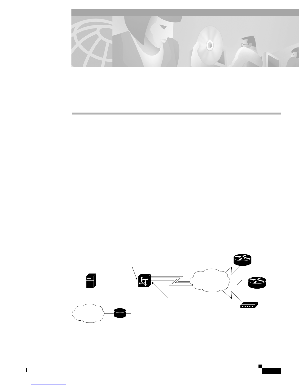
In the network topology shown in Figure 2-1, the PRI telephone number assigned to the Cisco AS5300
at the central headquarters site (hq-sanjose) is 4085551234. This number is often called the hunt group
number, which distributes calls among the available B channels. All four PRI trunks on the Cisco
AS5300 are assigned to this number by the PRI provider. The directory numbers for the remote devices
are configured on the Cisco AS5300 and then, subsequently configured on the remote devices
themselves.
2
The subnet 10.1.2.0 255.255.255.0 is configured on the Cisco AS5300 and is used for the loopback
interface and the local IP address pools as described in Chapter 1, “Dial Case Study Overview”.
Figure 2-1 Case Study Scenario Network Topology from the Perspective of the Cisco AS5300
Cisco 766
remote LAN
DNS
server
10.2.2.3
IP network
Table 2-1 provides detailed information about each end of the connection. This is the network
administrator’s top-level design table and is used in conjunction with the network topology diagram
shown in Figure 2-1 for planning and organizing the network.
10.1.1.10
255.255.255.0
Backhaul
router
Cisco
AS5300
Four T1 PRI lines
Interface dialer
10.1.254.1
255.255.255.0
PSTN
Cisco 1604
remote LAN
Modem
client
15580
Cisco IOS Dial Services Quick Configuration Guide
2-1
Page 2

Overview of Tasks
Table 2-1 Case Study Network Device Characteristics
Chapter 2 Configuring the Cisco AS5300 Network Access Server
Site Hardware WAN IP Address
Cisco AS5300 10.1.254.1
255.255.255.0
Dialer Interface
Cisco AS5300 10.1.2.0
255.255.255.0
Loopback Interface
Cisco 1604 10.1.254.4
255.255.255.0
Cisco 766 10.1.254.3
255.255.255.0
Note Be sure to use your own host names and passwords. For example, hq-sanjose, soho-tahoe,
and tahoe-pw are for this case study only.
Overview of Tasks
Do the following tasks to configure the Cisco AS5300 network access server (NAS):
Ethernet IP
Address Assigned Phone Number
10.1.1.10
255.255.255.0
10.1.4.1
255.255.255.0
10.1.3.1
255.255.255.0
4085551234 hq-sanjose hq-sanjose-pw
Directory number =
5125554433
Directory number =
5305558084
Host Name/
User Name
robo-austin austin-pw
soho-tahoe tahoe-pw
Username
Password
Task 1—Setting Up Basic Configuration Parameters:
Step 1—Verifying the Startup Configuration
Step 2—Configuring the Host Name, Password, and Time Stamps
Step 3—Configuring Local AAA Security
Task 2—Setting Up Asynchronous Shell Services:
Step 1—Configuring the Fast Ethernet 100BaseT Interface
Step 2—Configuring the T1 Controllers
Step 3—Configuring the Serial Channels to Let Modem Calls Come In
Step 4—Configuring the Modems and Lines
Step 5—Testing Async Shell Connections
Task 3—Setting Up Asynchronous PPP services:
Step 1—Setting Up IP Address Pools
Step 2—Configuring the Group-Async Interface
Step 3—Testing Async PPP Connections
Task 4—Setting Up Synchronous PPP Services:
Step 1—Configuring Dial-on-Demand Routing
Step 2—Configuring Parameters for Remote LAN Sites
Step 3—Configuring a Default Gateway (Backhaul) Routing Protocol
Step 4—Confirming the Final Running Configuration
Cisco IOS Dial Services Quick Configuration Guide
2-2
Page 3

Chapter 2 Configuring the Cisco AS5300 Network Access Server
Task 1—Setting Up Basic Configuration Parameters
Step 5—Saving the Configuration
Step 6—Testing Sync PPP Connections to Remote LANs
Step 7—Adding More Remote LAN Sites as Needed
Task 1—Setting Up Basic Configuration Parameters
When you first power up the Cisco AS5300, it will have to be configured to your particular needs. Verify
that you have a blank startup configuration, and configure it to your particular site needs by doing the
following steps:
Step 1—Verifying the Startup Configuration
If the startup configuration running inside the Cisco AS5300 is blank, the following screen appears at
bootup. The automatic setup script is engaged.
Copyright (c) 1994-1999 by cisco Systems, Inc.
AS5300 processor with 32768 Kbytes of main memory
program load complete, entry point: 0x80008000, size: 0xf4b10
Self decompressing the image : #################################################
################################################################################
################################################################################
################################################################################
################################################################################
################## [OK]
Restricted Rights Legend
Use, duplication, or disclosure by the Government is
subject to restrictions as set forth in subparagraph
(c) of the Commercial Computer Software - Restricted
Rights clause at FAR sec. 52.227-19 and subparagraph
(c) (1) (ii) of the Rights in Technical Data and Computer
Software clause at DFARS sec. 252.227-7013.
cisco Systems, Inc.
170 West Tasman Drive
San Jose, California 95134-1706
Cisco Internetwork Operating System Software
IOS (tm) 5300 Software (C5300-JS-M), Version 12.0(5)
Copyright (c) 1986-1999 by cisco Systems, Inc.
Compiled Tue 07-Nov-99 15:26 by xxxx
Image text-base: 0x600088E8, data-base: 0x608F4000
cisco AS5300 (R4K) processor (revision A.04) with 32768K/8192K bytes of memory.
Processor board ID 04614948
R4700 processor, Implementation 33, Revision 1.0 (512KB Level 2 Cache)
Bridging software.
X.25 software, Version 3.0.0.
SuperLAT software copyright 1996 by Meridian Technology Corp).
TN3270 Emulation software.
Primary Rate ISDN software, Version 1.1.
Backplane revision 1
Manufacture Cookie is not programmed.
1 Ethernet/IEEE 802.3 interface(s)
1 FastEthernet/IEEE 802.3 interface(s)
96 terminal line(s)
Cisco IOS Dial Services Quick Configuration Guide
2-3
Page 4

Task 1—Setting Up Basic Configuration Parameters
4 Channelized T1/PRI port(s)
128K bytes of non-volatile configuration memory.
16384K bytes of processor board System flash (Read/Write)
4096K bytes of processor board Boot flash (Read/Write)
Cisco Internetwork Operating System Software
IOS (tm) 5300 Software (C5300-JS-M), Version 12.0(5),
Copyright (c) 1986-1999 by cisco Systems, Inc.
Compiled Tue 07-Nov-99 15:26 by xxx
00:00:50: %MICA-5-BOARDWARE_RUNNING: Slot 2 is running boardware version 2.5.0.8
--- System Configuration Dialog ---
At any point you may enter a question mark '?' for help.
Use ctrl-c to abort configuration dialog at any prompt.
Default settings are in square brackets '[]'.
Would you like to enter the initial configuration dialog? [yes]: no
Press RETURN to get started!
Router>
Enter no when you are asked the question, “Would you like to enter the initial configuration dialog?
[yes]: ”
Would you like to enter the initial configuration dialog? [yes]: no
Chapter 2 Configuring the Cisco AS5300 Network Access Server
Press RETURN to get started!
Router>
In this case study, the Cisco AS5300 is manually configured by using the Cisco IOS software.
The automatic setup script is not used.
Note Enter the show version command to see if the access server is recognizing all its modem
cards. For example, the output field “96 terminal line(s)” indicates that the chassis can find
all 96 integrated modems.
Step 2—Configuring the Host Name, Password, and Time Stamps
Assign a host name to the Cisco AS5300, enable basic security, and turn on timestamping.
• Assigning a host name helps you to distinguish between different network devices.
• Enabling passwords helps you to prevent unauthorized configuration changes.
• Setting time stamps helps you to trace debug output for testing connections. Not knowing exactly
when an event occurs hinders you from examining background processes.
To configure the host name, enable password, and time stamps, use the following steps beginning in
user EXEC mode:
Step 1 Enter privileged EXEC mode.
Router> enable
Cisco IOS Dial Services Quick Configuration Guide
2-4
Page 5

Chapter 2 Configuring the Cisco AS5300 Network Access Server
Step 2 Enter global configuration mode. If the logging output generated by the access server interferes with
your terminal screen, redisplay your current command line by using the Tab key.
Router# configure terminal
Enter configuration commands, one per line. End
with CNTL/Z.
Step 3 Assign a host name to the access server. The router prompt changes from Router(config)# to
hq-sanjose(config)#. This host name is typically used during authentication with PPP peers.
Router(config)# hostname hq-sanjose
Step 4 Enter a secret enable password that secures privileged EXEC mode. Make sure to change “letmein” to
your own secret password.
hq-sanjose(config)# enable secret letmein
Step 5 Encrypt passwords in the configuration file for greater security.
hq-sanjose(config)# service password-encryption
Step 6 Enable millisecond time stamping on debug and logging output. Time stamps are useful for detailed
access troubleshooting.
hq-sanjose(config)# service timestamps debug datetime msec
hq-sanjose(config)# service timestamps log datetime msec
Task 1—Setting Up Basic Configuration Parameters
Verifying the Host Name, Password, and Time Stamp Configuration
Log in with your new enable password.
Step 1 Exit out of privileged EXEC mode by using the disable command. The prompt changes from
hq-sanjose# to hq-sanjose>.
Step 2 Enter the enable command followed by your password.
Step 3 Enter the show privilege command to show the current security privilege level:
hq-sanjose# disable
hq-sanjose> enable
Password: letmein
hq-sanjose# show privilege
Current privilege level is 15
hq-sanjose#
Cisco IOS Dial Services Quick Configuration Guide
2-5
Page 6

Task 1—Setting Up Basic Configuration Parameters
Step 4 Enter the show running command to show the current running configuration:
hq-sanjose# show running
Building configuration...
Current configuration:
!
version 12.0(5)
service timestamps debug datetime msec
service timestamps log datetime msec
service password-encryption
!
hostname hq-sanjose
!
enable secret 5 $1$.voA$9/8.Zoil3jeWJMP6hEE6U0
!
----- snip ----
Tips
If you have trouble:
• Make sure the Caps Lock key is off.
• Make sure you have entered the correct passwords. Passwords are case sensitive.
• Password protection is very important. Enter the show tech-support command to report system
configuration information to Cisco TAC:
hq-sanjose# show tech-support ?
ipmulticast IP multicast related information
page Page through output
password Include passwords
rsvp IP RSVP related information
<cr>
Chapter 2 Configuring the Cisco AS5300 Network Access Server
Step 3—Configuring Local AAA Security
The Cisco IOS security model to use on all Cisco devices is authentication, authorization, and
accounting (AAA). AAA provides the primary framework through which you set up access control on
the access server.
• Authentication—Who are you?
• Authorization—What can you do?
• Accounting—What did you do?
In this case study, the same authentication method is used on all interfaces. AAA is set up to use the
local database configured on the Cisco AS5300. This local database is created with the username
configuration commands.
Note Although configuring your local AAA is not required here, it is considered “best
practices” to do so when first setting up your router. Setting up this local AAA prevents
unauthorized access and configuration changes.
Cisco IOS Dial Services Quick Configuration Guide
2-6
Page 7

Chapter 2 Configuring the Cisco AS5300 Network Access Server
To configure local AAA security, enter the following commands beginning in global configuration
mode:
Note Make sure to change “joe-admin” to your own username and “joe-password” to your own
password.
Step 1 Create a local login database and username for yourself. This step also prevents you from getting locked
out of the access server.
hq-sanjose(config)# username joe-admin password joe-password
Step 2 Initiate the AAA access control system. This step immediately locks down login and PPP
authentication.
hq-sanjose(config)# aaa new-model
Step 3 Configure AAA to perform login authentication by using the local username database. The login
keyword authenticates shell/EXEC users.
hq-sanjose(config)# aaa authentication login default local
Task 1—Setting Up Basic Configuration Parameters
Step 4 Configure PPP authentication to use the local database if the session was not already authenticated by
login.
hq-sanjose(config)# aaa authentication ppp default if-needed local
Note After you finish setting up basic security, you can enhance the security solution by
extending it to an external TACACS+ or RADIUS server. This case study describes only
local AAA security.
Verifying Local AAA Security Configuration
Step 1 Log in with your username:password.
Step 2 Enter the login command at the EXEC shell prompt. If you get in, the login authentication is working
with your local username. Do not disconnect your access server session until you can log in
successfully. (If you get locked out, recover your password by rebooting the access server.)
hq-sanjose# login
User Access Verification
Username: joe-admin
Password: joe-password
hq-sanjose#
Cisco IOS Dial Services Quick Configuration Guide
2-7
Page 8

Task 2—Setting Up Asynchronous Shell Services
Step 3 Enter the show running command to view the current configuration of the AAA parameters:
hq-sanjose# show running
Building configuration...
Current configuration:
!
version 12.0(5)
service timestamps debug datetime msec
service timestamps log datetime msec
service password-encryption
!
hostname hq-sanjose
!
aaa new-model
aaa authentication login default local
aaa authentication ppp default if-needed local
enable secret 5 $1$.voA$9/8.Zoil3jeWJMP6hEE6U0
!
username joe-admin password 7 <removed>
!
----- snip ----
Chapter 2 Configuring the Cisco AS5300 Network Access Server
Task 2—Setting Up Asynchronous Shell Services
When you have configured the preliminary parameters such as your host name, password, timestamps
and local AAA security on the Cisco AS5300, you can then move on to setting up the asynchronous
shell services, which provide access through the Cisco IOS CLI EXEC shell to terminal services (no
PPP) for the following tasks:
• Changing passwords
• Accessing menus
• Troubleshooting modem connections
• Accessing other network resources with Telnet
Step 1—Configuring the Fast Ethernet 100BaseT Interface
Assign an IP address, line speed, and duplex mode to the Cisco AS5300’s Fast Ethernet interface, which
supports 10- and 100-Mbps speeds.
The default priority search order for autonegotiating the line speed is as follows:
1. 100Base-TX full duplex
2. 100Base-TX half duplex
3. 10Base-T full duplex
4. 10Base-T half duplex
To configure the Fast Ethernet 100Base-TX interface, enter the following commands beginning in
global configuration mode:
Cisco IOS Dial Services Quick Configuration Guide
2-8
Page 9

Chapter 2 Configuring the Cisco AS5300 Network Access Server
Step 1 Configure the IP address and subnet mask on the Fast Ethernet interface.
hq-sanjose(config)# interface fastethernet 0
hq-sanjose(config-if)# ip address 10.1.1.10 255.255.255.0
Step 2 Set autonegotiation for the line speed based on the peer routers, hubs, and switch media.
hq-sanjose(config-if)# speed auto
Step 3 Set autonegotiation for duplex mode.
hq-sanjose(config-if)# duplex auto
Step 4 Bring up the interface. This command changes the state of the interface from administratively down to
up.
hq-sanjose(config-if)# no shutdown
%LINK-3-UPDOWN: Interface FastEthernet0, changed state to up
Verifying the Fast Ethernet 100BaseT Interface
Task 2—Setting Up Asynchronous Shell Services
Step 1 Enter the show ip interface brief command to view the interface’s status. The “up” field appears under
the Status and Protocol columns in the displayed output. The fields “
down” or “administratively down”
indicate a connection problem:
hq-sanjose# show ip interface brief fastethernet 0
Interface IP-Address OK? Method Status Protocol
FastEthernet0 10.1.1.10 YES manual up up
Step 2 Ping a device in your network, such as a default gateway (backhaul router) or the backbone gateway:
hq-sanjose# ping 10.1.1.1
Type escape sequence to abort.
Sending 5, 100-byte ICMP Echos to 10.1.1.1, timeout is 2 seconds:
!!!!!
Success rate is 100 percent (5/5), round-trip min/avg/max = 4/5/8 ms
Step 3 Enter the show interface fastethernet 0 command to see detailed interface information. Look for the
display field “
FastEthernet 0 is up, line protocol is up.” This means that the access server sees
its own sent and received keepalives.
hq-sanjose# show interface fastethernet 0
FastEthernet0 is up, line protocol is up
Hardware is DEC21140AE, address is 00e0.1e6b.2ffb (bia 00e0.1e6b.2ffb)
Internet address is 10.1.1.10 /24
MTU 1500 bytes, BW 100000 Kbit, DLY 100 usec, rely 255/255, load 1/255
Encapsulation ARPA, loopback not set, keepalive set (10 sec), auto duplex,
100BaseTX/FX, auto speed
ARP type: ARPA, ARP Timeout 04:00:00
Last input 00:00:05, output 00:00:05, output hang never
Last clearing of "show interface" counters never
Queueing strategy: fifo
Output queue 0/40, 0 drops; input queue 0/120, 0 drops
5 minute input rate 0 bits/sec, 0 packets/sec
5 minute output rate 0 bits/sec, 0 packets/sec
282 packets input, 68476 bytes, 0 no buffer
Received 282 broadcasts, 0 runts, 0 giants, 0 throttles
0 input errors, 0 CRC, 0 frame, 0 overrun, 0 ignored, 0 abort
Cisco IOS Dial Services Quick Configuration Guide
2-9
Page 10

Task 2—Setting Up Asynchronous Shell Services
0 watchdog, 0 multicast
0 input packets with dribble condition detected
176 packets output, 16936 bytes, 0 underruns
0 output errors, 0 collisions, 0 interface resets
0 babbles, 0 late collision, 0 deferred
0 lost carrier, 0 no carrier
0 output buffer failures, 0 output buffers swapped out
Step 4 Enter the show running command to view the current configuration of the FastEthernet 100BaseT
interface:
hq-sanjose# show running
Building configuration...
Current configuration:
!
----- snip ---!
interface FastEthernet0
ip address 10.1.1.10 255.255.255.0
no ip directed-broadcast
no ip route-cache
no ip mroute-cache
duplex auto
speed auto
!
----- snip ----
Chapter 2 Configuring the Cisco AS5300 Network Access Server
Tips
If you have trouble:
• Make sure the cable connections are not loose or disconnected.
• Make sure you are using the correct IP address.
• An auto-configuration of the Fast Ethernet interface may not work as expected if the Cisco device
is connected to a third-party switch. Using the step-by-step configuration described above may be
a good work-around if you have problems getting the interface to work.
Step 2—Configuring the T1 Controllers
Configure the Cisco AS5300’s T1 controllers to allow calls to come into the NAS from the public
switched telephone network (PSTN) cloud. You must specify the following information for each
controller:
• Framing type
• Line code type
• Clock source
• Timeslot assignments
To configure the controllers, enter the following commands beginning in global configuration mode:
Step 1 Enter your telephone company’s switch type. This example uses primary national ISDN 1.
hq-sanjose(config)# isdn switch-type primary-ni
Cisco IOS Dial Services Quick Configuration Guide
2-10
Page 11

Chapter 2 Configuring the Cisco AS5300 Network Access Server
Step 2 Enter controller configuration mode for the first T1 controller, which is 0. The controller ports are
labeled 0 through 3 on the quad T1/PRI card.
hq-sanjose(config)# controller t1 0
Step 3 Enter the T1 framing type. This example uses extended super frame.
hq-sanjose(config-controller)# framing esf
Step 4 Enter the T1 line code type. This example uses B8ZS.
hq-sanjose(config-controller)# linecode b8zs
Step 5 Configure the access server to get its primary clock (timing signal) from the T1 line assigned to
controller 0. Line clocking comes from the remote switch.
hq-sanjose(config-controller)# clock source line primary
Step 6 Assign all 24 T1 timeslots as ISDN PRI channels. After you enter this command, a D-channel serial
interface is instantly created (for example S0:23, S1:23, and so on) in the configuration file and the
individual B-channel serial interfaces (for example S0:0, S0:1, ...). The D-channel interface functions
like a dialer for all the 23 B channels using the controller.
hq-sanjose(config-controller)# pri-group timeslots 1-24
Task 2—Setting Up Asynchronous Shell Services
Step 7 Exit back to global configuration mode.
hq-sanjose(config-controller)# exit
Step 8 Configure the second controller, controller T1 1. Set the clocking to secondary 1. If the line clocking
from controller T1 0 fails, the Cisco AS5300 will receive its clocking from controller T1 1.
hq-sanjose(config#) controller t1 1
hq-sanjose(config-controller)# framing esf
hq-sanjose(config-controller)# linecode b8zs
hq-sanjose(config-controller)# clock source line secondary 1
hq-sanjose(config-controller)# pri-group timeslots 1-24
hq-sanjose(config-controller)# exit
Step 9 Configure the remaining two controllers. Cisco IOS Release 12.0 and later releases support use of the
clock source line secondary x command. This enables the Cisco AS5300 to continue to receive clock
(timing signal) from the telephone company or the next remaining controller if a previous controller
goes down. This would not be possible if the remaining T1 controllers were set to internal.
hq-sanjose(config#) controller t1 2
hq-sanjose(config-controller)# framing esf
hq-sanjose(config-controller)# linecode b8zs
hq-sanjose(config-controller)# clock source line secondary 2
hq-sanjose(config-controller)# pri-group timeslots 1-24
hq-sanjose(config-controller)# exit
hq-sanjose(config#) controller t1 3
hq-sanjose(config-controller)# framing esf
hq-sanjose(config-controller)# linecode b8zs
hq-sanjose(config-controller)# clock source line secondary 3
hq-sanjose(config-controller)# pri-group timeslots 1-24
hq-sanjose(config-controller)# exit
hq-sanjose(config#)
Cisco IOS Dial Services Quick Configuration Guide
2-11
Page 12

Task 2—Setting Up Asynchronous Shell Services
Verifying the T1 Controller Configuration
Step 1 Enter the show controller t1 command. The output from this command enables you to determine when
and where errors occur.
Note the display field “
hq-sanjose# show controller t1
T1 0 is up.
No alarms detected.
Version info of slot 0: HW: 2, Firmware: 16, PLD Rev: 0
Manufacture Cookie Info:
EEPROM Type 0x0001, EEPROM Version 0x01, Board ID 0x42,
Board Hardware Version 1.0, Item Number 73-2217-4,
Board Revision A0, Serial Number 07557185,
PLD/ISP Version 0.0, Manufacture Date 17-Dec-1997.
Framing is ESF, Line Code is B8ZS, Clock Source is Line Primary.
Data in current interval (25 seconds elapsed):
0 Line Code Violations, 0 Path Code Violations
0 Slip Secs, 0 Fr Loss Secs, 0 Line Err Secs, 0 Degraded Mins
0 Errored Secs, 0 Bursty Err Secs, 0 Severely Err Secs, 0 Unavail Secs
Total Data (last 24 hours)
0 Line Code Violations, 0 Path Code Violations,
0 Slip Secs, 0 Fr Loss Secs, 0 Line Err Secs, 0 Degraded Mins,
0 Errored Secs, 0 Bursty Err Secs, 0 Severely Err Secs, 0 Unavail Secs
T1 1 is up.
No alarms detected.
Version info of slot 0: HW: 2, Firmware: 16, PLD Rev: 0
Manufacture Cookie Info:
EEPROM Type 0x0001, EEPROM Version 0x01, Board ID 0x42,
Board Hardware Version 1.0, Item Number 73-2217-4,
Board Revision A0, Serial Number 07557185,
PLD/ISP Version 0.0, Manufacture Date 17-Dec-1997.
Framing is ESF, Line Code is B8ZS, Clock Source is Line Secondary 1.
Data in current interval (827 seconds elapsed):
0 Line Code Violations, 0 Path Code Violations
0 Slip Secs, 0 Fr Loss Secs, 0 Line Err Secs, 0 Degraded Mins
0 Errored Secs, 0 Bursty Err Secs, 0 Severely Err Secs, 0 Unavail Secs
Total Data (last 24 hours)
0 Line Code Violations, 0 Path Code Violations,
0 Slip Secs, 0 Fr Loss Secs, 0 Line Err Secs, 0 Degraded Mins,
0 Errored Secs, 0 Bursty Err Secs, 0 Severely Err Secs, 0 Unavail Secs
T1 2 is administratively down.
Transmitter is sending remote alarm.
Receiver has loss of signal.
Version info of slot 0: HW: 2, Firmware: 16, PLD Rev: 0
Manufacture Cookie Info:
EEPROM Type 0x0001, EEPROM Version 0x01, Board ID 0x42,
Board Hardware Version 1.0, Item Number 73-2217-4,
Board Revision A0, Serial Number 07557185,
PLD/ISP Version 0.0, Manufacture Date 17-Dec-1997.
Framing is ESF, Line Code is B8ZS, Clock Source is Line Secondary 2.
Data in current interval (868 seconds elapsed):
3 Line Code Violations, 0 Path Code Violations
0 Slip Secs, 868 Fr Loss Secs, 2 Line Err Secs, 0 Degraded Mins
0 Errored Secs, 0 Bursty Err Secs, 0 Severely Err Secs, 868 Unavail Secs
Total Data (last 24 hours)
182 Line Code Violations, 0 Path Code Violations,
1 Slip Secs, 86400 Fr Loss Secs, 125 Line Err Secs, 0 Degraded Mins,
0 Errored Secs, 0 Bursty Err Secs, 0 Severely Err Secs, 86400 Unavail Secs
T1 3 is administratively down.
Transmitter is sending remote alarm.
Data in current interval”:
Chapter 2 Configuring the Cisco AS5300 Network Access Server
Cisco IOS Dial Services Quick Configuration Guide
2-12
Page 13

Chapter 2 Configuring the Cisco AS5300 Network Access Server
Receiver has loss of signal.
Version info of slot 0: HW: 2, Firmware: 16, PLD Rev: 0
Manufacture Cookie Info:
EEPROM Type 0x0001, EEPROM Version 0x01, Board ID 0x42,
Board Hardware Version 1.0, Item Number 73-2217-4,
Board Revision A0, Serial Number 07557185,
PLD/ISP Version 0.0, Manufacture Date 17-Dec-1997.
Framing is ESF, Line Code is B8ZS, Clock Source is Line Secondary 3.
Data in current interval (142 seconds elapsed):
0 Line Code Violations, 0 Path Code Violations
0 Slip Secs, 142 Fr Loss Secs, 0 Line Err Secs, 0 Degraded Mins
0 Errored Secs, 0 Bursty Err Secs, 0 Severely Err Secs, 142 Unavail Secs
Total Data (last 24 hours)
12 Line Code Violations, 0 Path Code Violations,
0 Slip Secs, 86400 Fr Loss Secs, 8 Line Err Secs, 0 Degraded Mins,
0 Errored Secs, 0 Bursty Err Secs, 0 Severely Err Secs, 86400 Unavail Secs
Step 2 Enter the show controller t1 number command to view the statistics for a particular T1 controller.
If counters are increasing on a specific T1 controller, see the error statistics. Error counters are recorded
for a 24-hour period in 15-minute intervals. You must specify a specific controller number to see this
detailed information. Focus on the current interval.
In the following example, note that the frame loss and line errors present in data intervals 1 through 4
cleared in the current data interval.
Task 2—Setting Up Asynchronous Shell Services
Note Errors are reported to the controller’s counters each time there is an error.
Therefore, clear the counters by using the clear controller t1 number command
before you look for current error statistics. Error counters stop increasing when
the controller is configured correctly.
hq-sanjose# show controller t1 0
T1 0 is up.
No alarms detected.
Version info of slot 0: HW: 2, Firmware: 16, PLD Rev: 0
Manufacture Cookie Info:
EEPROM Type 0x0001, EEPROM Version 0x01, Board ID 0x42,
Board Hardware Version 1.0, Item Number 73-2217-4,
Board Revision A0, Serial Number 07557185,
PLD/ISP Version 0.0, Manufacture Date 17-Dec-1997.
Framing is ESF, Line Code is B8ZS, Clock Source is Line Primary.
Data in current interval (72 seconds elapsed):
0 Line Code Violations, 0 Path Code Violations
0 Slip Secs, 0 Fr Loss Secs, 0 Line Err Secs, 0 Degraded Mins
0 Errored Secs, 0 Bursty Err Secs, 0 Severely Err Secs, 0 Unavail Secs
Data in Interval 1:
0 Line Code Violations, 0 Path Code Violations
0 Slip Secs, 405 Fr Loss Secs, 14 Line Err Secs, 0 Degraded Mins
0 Errored Secs, 0 Bursty Err Secs, 0 Severely Err Secs, 405 Unavail Secs
Data in Interval 2:
0 Line Code Violations, 0 Path Code Violations
0 Slip Secs, 450 Fr Loss Secs, 1 Line Err Secs, 0 Degraded Mins
0 Errored Secs, 0 Bursty Err Secs, 0 Severely Err Secs, 450 Unavail Secs
Data in Interval 3:
0 Line Code Violations, 0 Path Code Violations
0 Slip Secs, 450 Fr Loss Secs, 1 Line Err Secs, 0 Degraded Mins
0 Errored Secs, 0 Bursty Err Secs, 0 Severely Err Secs, 450 Unavail Secs
-------------------------------- snip ------------------------------------------
Cisco IOS Dial Services Quick Configuration Guide
2-13
Page 14

Task 2—Setting Up Asynchronous Shell Services
Step 3 Enter the show running command to see the current configuration of all of the Cisco AS5300 T1
controllers:
hq-sanjose# show running
Building configuration...
Current configuration:
!
----- snip ---!
isdn switch-type primary-ni
!
controller T1 0
framing esf
clock source line primary
linecode b8zs
pri-group timeslots 1-24
!
controller T1 1
framing esf
clock source line secondary 1
linecode b8zs
pri-group timeslots 1-24
!
controller T1 2
framing esf
clock source line secondary 2
linecode b8zs
pri-group timeslots 1-24
!
controller T1 3
framing esf
clock source line secondary 3
linecode b8zs
pri-group timeslots 1-24
!
----- snip ----
Chapter 2 Configuring the Cisco AS5300 Network Access Server
Tips
If you have trouble:
• Make sure the controller reports “up.”
• Check if errors are reported in the current interval.
Step 3—Configuring the Serial Channels to Let Modem Calls Come In
Configure the D channels to allow incoming voice calls to be routed to the Cisco AS5300’s integrated
modems. The D channel is the signalling channel that controls the calls coming in on the ISDN B
channels.
Later, in the section “Step 1—Configuring Dial-on-Demand Routing” in Task 4, the D-channel
configuration can be expanded to also accept ISDN synchronous PPP calls from the remote offices.
However, Cisco recommends getting only modem users configured and running at this stage in the
process.
Cisco IOS Dial Services Quick Configuration Guide
2-14
Page 15

Chapter 2 Configuring the Cisco AS5300 Network Access Server
To configure the serial channels, enter the following commands beginning in global configuration
mode:
Step 1 Access the configuration mode for the D-channel serial interface that corresponds to controller T1 0.
The behavior of B channels S0:0 through S0:22 is controlled by the configuration instructions provided
for S0:23. This concept is also true for the other remaining D-channel configurations.
hq-sanjose(config)# interface serial 0:23
Step 2 Enable analog modem voice calls coming in over the B channels to be connected to the integrated
modems.
hq-sanjose(config-if)# isdn incoming-voice modem
hq-sanjose(config-if)# no shutdown
Step 3 Return to global configuration mode.
hq-sanjose(config-if)# exit
Step 4 Configure the three remaining D channels with the same settings.
hq-sanjose(config)# interface serial 1:23
hq-sanjose(config-if)# isdn incoming-voice modem
hq-sanjose(config-if)# no shutdown
hq-sanjose(config-if)# exit
hq-sanjose(config)# interface serial 2:23
hq-sanjose(config-if)# isdn incoming-voice modem
hq-sanjose(config-if)# no shutdown
hq-sanjose(config-if)# exit
hq-sanjose(config)# interface serial 3:23
hq-sanjose(config-if)# isdn incoming-voice modem
hq-sanjose(config-if)# no shutdown
hq-sanjose(config-if)# exit
hq-sanjose(config)#
Task 2—Setting Up Asynchronous Shell Services
Verifying the Serial Channel Configuration
Step 1 Enter the show interface serial 0:23 command to display the serial channel interface configuration.
hq-sanjose# show interface serial 0:23
Serial0:23 is up, line protocol is up (spoofing)
Hardware is DSX1
MTU 1500 bytes, BW 64 Kbit, DLY 20000 usec, rely 255/255, load 1/255
Encapsulation PPP, loopback not set
DTR is pulsed for 1 seconds on reset
Last input 00:00:12, output 00:00:12, output hang never
Last clearing of "show interface" counters never
Input queue: 0/75/0 (size/max/drops); Total output drops: 0
Queueing strategy: weighted fair
Output queue: 0/1000/64/0 (size/max total/threshold/drops)
Conversations 0/1/256 (active/max active/max total)
Reserved Conversations 0/0 (allocated/max allocated)
5 minute input rate 0 bits/sec, 0 packets/sec
5 minute output rate 0 bits/sec, 0 packets/sec
937 packets input, 19612 bytes, 0 no buffer
Received 0 broadcasts, 0 runts, 2 giants, 0 throttles
2 input errors, 0 CRC, 0 frame, 0 overrun, 0 ignored, 0 abort
945 packets output, 4263 bytes, 0 underruns
0 output errors, 0 collisions, 4 interface resets
Cisco IOS Dial Services Quick Configuration Guide
2-15
Page 16

Task 2—Setting Up Asynchronous Shell Services
0 output buffer failures, 0 output buffers swapped out
3 carrier transitions
Timeslot(s) Used:24, Transmitter delay is 0 flags
The term “spoofing” means that the interface is presenting itself to the Cisco IOS software as up and
operational. This interface can now receive routes. There are 23 more channels behind this interface that
you do not see (for example, S0:0, S0:1, and so on). The D channel decides which serial channel
(B channel) to assign to an incoming call.
Note The packet counters shown by the interface serial 0:23 command are for
signalling traffic only. Data traffic passes through S0:0 through S0:22.
Step 2 Enter the show isdn status command to view the ISDN layer information.
This output shows that Layer 1 and Layer 2 are enabled and active and that there are no active Layer 3
ISDN calls.
hq-sanjose# show isdn status
The current ISDN Switchtype = primary-ni
ISDN Serial0:23 interface
Layer 1 Status:
ACTIVE
Layer 2 Status:
TEI = 0, State = MULTIPLE_FRAME_ESTABLISHED
Layer 3 Status:
No Active Layer 3 Call(s)
Activated dsl 0 CCBs = 0
Total Allocated ISDN CCBs = 0
ISDN Serial1:23 interface
Layer 1 Status:
ACTIVE
Layer 2 Status:
TEI = 0, State = MULTIPLE_FRAME_ESTABLISHED
Layer 3 Status:
No Active Layer 3 Call(s)
Activated dsl 1 CCBs = 0
Total Allocated ISDN CCBs = 0
ISDN Serial2:23 interface
Layer 1 Status:
ACTIVE
Layer 2 Status:
TEI = 0, State = MULTIPLE_FRAME_ESTABLISHED
Layer 3 Status:
No Active Layer 3 Call(s)
Activated dsl 2 CCBs = 0
Total Allocated ISDN CCBs = 0
ISDN Serial3:23 interface
Layer 1 Status:
ACTIVE
Layer 2 Status:
TEI = 0, State = MULTIPLE_FRAME_ESTABLISHED
Layer 3 Status:
No Active Layer 3 Call(s)
Activated dsl 3 CCBs = 0
Total Allocated ISDN CCBs = 0
Chapter 2 Configuring the Cisco AS5300 Network Access Server
Note the following information:
• Layer 1 Status should be “Active.”
Cisco IOS Dial Services Quick Configuration Guide
2-16
Page 17

Chapter 2 Configuring the Cisco AS5300 Network Access Server
• Layer 2 Status should be “Multiple_Frame_Established.” (It might take several seconds for Layer 2
status to appear.)
• Layer 3 Status should be “No Active Layer 3 Call(s).”
Step 3 Enter the show isdn service command to determine which channels have active calls and if all the
individual channels are in service. In this example, note that there are 8 serial channels under each
D channel that calls cannot use. T1 lines are used in this case study (not E1):
hq-sanjose# show isdn service
PRI Channel Statistics:
ISDN Se0:23, Channel (1-31)
Activated dsl 0
State (0=Idle 1=Propose 2=Busy 3=Reserved 4=Restart 5=Maint)
0 0 2 0 0 0 0 0 0 0 0 0 0 0 0 0 0 0 0 0 0 0 0 3 3 3 3 3 3 3 3
Channel (1-31) Service (0=Inservice 1=Maint 2=Outofservice)
0 0 0 0 0 0 0 0 0 0 0 0 0 0 0 0 0 0 0 0 0 0 0 2 2 2 2 2 2 2 2
ISDN Se1:23, Channel (1-31)
Activated dsl 0
State (0=Idle 1=Propose 2=Busy 3=Reserved 4=Restart 5=Maint)
0 0 0 0 0 0 0 0 0 0 0 0 0 0 0 0 0 0 0 0 0 0 0 3 3 3 3 3 3 3 3
Channel (1-31) Service (0=Inservice 1=Maint 2=Outofservice)
0 0 0 0 0 0 0 0 0 0 0 0 0 0 0 0 0 0 0 0 0 0 0 2 2 2 2 2 2 2 2
ISDN Se2:23, Channel (1-31)
Activated dsl 0
State (0=Idle 1=Propose 2=Busy 3=Reserved 4=Restart 5=Maint)
0 0 0 0 0 0 0 0 0 0 0 0 0 0 0 0 0 0 0 0 0 0 0 3 3 3 3 3 3 3 3
Channel (1-31) Service (0=Inservice 1=Maint 2=Outofservice)
0 0 0 0 0 0 0 0 0 0 0 0 0 0 0 0 0 0 0 0 0 0 0 2 2 2 2 2 2 2 2
ISDN Se3:23, Channel (1-31)
Activated dsl 0
State (0=Idle 1=Propose 2=Busy 3=Reserved 4=Restart 5=Maint)
0 0 0 0 0 0 0 0 0 0 0 0 0 0 0 0 0 0 0 0 0 0 0 3 3 3 3 3 3 3 3
Channel (1-31) Service (0=Inservice 1=Maint 2=Outofservice)
0 0 0 0 0 0 0 0 0 0 0 0 0 0 0 0 0 0 0 0 0 0 0 2 2 2 2 2 2 2 2
Task 2—Setting Up Asynchronous Shell Services
Step 4 Enter the show ip interface brief command to view the individual serial B channel interfaces. In the
following example, Serial 0:0 through Serial 0:22 are B channels and are associated to D channel
Serial 0:23:
hq-sanjose# show ip interface brief
Interface IP-Address OK? Method Status Protocol
Ethernet0 unassigned YES NVRAM administratively down down
FastEthernet0 10.1.1.10 YES manual up up
Serial0:0 unassigned YES unset down down
Serial0:1 unassigned YES unset down down
Serial0:2 unassigned YES unset down down
Serial0:3 unassigned YES unset down down
Serial0:4 unassigned YES unset down down
Serial0:5 unassigned YES unset down down
Serial0:6 unassigned YES unset down down
Serial0:7 unassigned YES unset down down
Serial0:8 unassigned YES unset down down
Serial0:9 unassigned YES unset down down
Serial0:10 unassigned YES unset down down
Serial0:11 unassigned YES unset down down
Serial0:12 unassigned YES unset down down
Serial0:13 unassigned YES unset down down
Serial0:14 unassigned YES unset down down
Serial0:15 unassigned YES unset down down
Serial0:16 unassigned YES unset down down
Serial0:17 unassigned YES unset down down
Serial0:18 unassigned YES unset down down
Serial0:19 unassigned YES unset down down
Cisco IOS Dial Services Quick Configuration Guide
2-17
Page 18

Task 2—Setting Up Asynchronous Shell Services
Serial0:20 unassigned YES unset down down
Serial0:21 unassigned YES unset down down
Serial0:22 unassigned YES unset down down
Serial0:23 unassigned YES unset down down
Step 5 Enter the show running command to see the current configuration of the D channels for the serial
interfaces:
hq-sanjose# show running
Building configuration...
Current configuration:
!
---- snip ---!
interface Serial0:23
no ip address
no ip directed-broadcast
isdn incoming-voice modem
!
interface Serial1:23
no ip address
no ip directed-broadcast
isdn incoming-voice modem
!
interface Serial2:23
no ip address
no ip directed-broadcast
isdn incoming-voice modem
!
interface Serial3:23
no ip address
no ip directed-broadcast
isdn incoming-voice modem
!
---- snip ----
Chapter 2 Configuring the Cisco AS5300 Network Access Server
Tips
If you have trouble:
• Be sure you have configured the correct ISDN switch type.
• Make sure no wires or cables are loose.
• The framing or line code types you entered might not match your telco’s settings. A Layer 2 error
indicates that the access server cannot communicate with the telco.
• Make sure the show controller t1 command’s current output shows no errors.
Step 4—Configuring the Modems and Lines
Configure the Cisco AS5300 internal modems and asynchronous lines after the ISDN channels are
operational. Each modem is directly mapped to a dedicated async line in the access server. After this
configuration is set up, the Cisco AS5300 is ready to take modem calls.
The modem speed 115200 bps and hardware flow control are the defaults for the integrated modems.
Cisco IOS Dial Services Quick Configuration Guide
2-18
Page 19

Chapter 2 Configuring the Cisco AS5300 Network Access Server
To configure the Cisco AS5300’s modems and asynchronous lines, enter the following commands
beginning in global configuration mode:
Step 1 Enter the range of modem lines to configure. In this example, the Cisco AS5300 has 96 integrated
modems.
hq-sanjose(config)# line 1 96
Step 2 Enable remote PPP users to dial in, bypass the EXEC facility, and automatically launch PPP on the line.
This and the next autoselect command provide for transparent launching of shell and PPP services on
the same lines.
hq-sanjose(config-line)# autoselect ppp
Step 3 Enter the autoselect during-login command to display the username:password prompt after modems
connect.
hq-sanjose(config-line)# autoselect during-login
Step 4 Set the modems to support incoming and outgoing modem calls.
hq-sanjose(config-line)# modem inout
Task 2—Setting Up Asynchronous Shell Services
Verifying the Modem and Line Configuration
Step 1 Enter the show running command to verify the configuration of the modems and lines:
hq-sanjose# show running
Building configuration...
Current configuration:
---- snip ---!
line 1 96
autoselect during-login
autoselect ppp
modem InOut
---- snip ----
Step 2 Send a voice call to the access server by using a standard POTS telephone. If you hear modem squelch
(tone) from the access server’s internal modem, the configuration works. See Figure 2-2.
Cisco IOS Dial Services Quick Configuration Guide
2-19
Page 20

Task 2—Setting Up Asynchronous Shell Services
Figure 2-2 Case Study Lab Environment for Testing an Incoming Voice Call
Chapter 2 Configuring the Cisco AS5300 Network Access Server
PSTN
PRI
DNIS
444-1234
POTS
Cisco AS5300 receiving
analog telephone call
Step 5—Testing Async Shell Connections
Now you are ready to send the first modem call into the Cisco AS5300. This step shows you how to do
the test and track the asynchronous data path taken by a single modem call.
Do this test by using a shell service, which verifies that the physical async data path is working. This is
the most efficient way to get quick test results in a simple test environment.
At this step, do not try to make complex services such as PPP-based Web browsing work, because you
still need to configure other elements first. This step is provided to ensure that the basic modem link is
functioning, and that you can access the shell/EXEC prompt remotely. To avoid problems, take a
layered approach to building a network.
Standard POTS
telephone
15987
2-20
Figure 2-3 shows a test PC running a terminal emulation program, such as HyperTerminal. This
program enables the test PC to make a modem-to-modem connection with the Cisco AS5300 over the
PSTN network.
Cisco IOS Dial Services Quick Configuration Guide
Page 21

Chapter 2 Configuring the Cisco AS5300 Network Access Server
Figure 2-3 Case Study Lab Environment for Testing Async Shell Connections
Task 2—Setting Up Asynchronous Shell Services
PSTN
POTS
PRI
555-1234
RS-232
Administrator's PC
Modem
Test PC
(configuration and logging)
Cisco AS5300
receiving call
from test PC
RS-232
console
15990
Step 1 Enter the following debug commands on the Cisco AS5300 to debug calls coming in to the integrated
modems.
These commands capture the call-switching module and ISDN connection messages:
hq-sanjose# debug modem csm
Modem Management Call Switching Module debugging is on
hq-sanjose# debug isdn q931
ISDN Q931 packets debugging is on
hq-sanjose# terminal monitor
% Console already monitors
Note The command terminal monitor is not required on the console, but would be required if
you were using a Telnet connection into the access servers. If you are not on a console,
you will need to type terminal monitor here.
Step 2 After you are finished with the test, turn off all debugging with the undebug all command.
Note The ISDN Q.931 messages display call information coming into the access server.
The modem call-switching module captures the calls getting routed to the internal
modems. The terminal monitor ensures that your EXEC session is receiving the
logging and debug output.
Step 3 From a terminal emulation program running on the test PC, enter atdt followed by the primary rate
interface (PRI) phone number assigned to the Cisco AS5300. In this case test, 5551234 is used.
Cisco IOS Dial Services Quick Configuration Guide
2-21
Page 22

Task 2—Setting Up Asynchronous Shell Services
If the modem successfully connects, a connect message followed by the terminal service EXEC login
prompt appears on the test PC.
atdt5551234
CONNECT 24000/REL - MNP
User Access Verification
Username: joe-admin
Password:
hq-sanjose>
Note The modem attached to the test PC sends out “CONNECT 24000/REL - MNP”
The Cisco AS5300 sends out “
“
Password:.” These messages confirm that you have end-to-end async shell
connectivity.
Interpret the debug messages that appear on the administrator’s terminal screen as a result of Step 2.
This debug output (shown after the comments) was created as the modem call came into the
Cisco AS5300 NAS.
Chapter 2 Configuring the Cisco AS5300 Network Access Server
User Access Verification,” “Username:,” and
The following comments apply to the debug output example:
a. See 20:43:35.906 through 20:43:35.918.
The setup message is received. The bearer capability is a voice call as indicated by 0x8090A2. The
calling party number is 5551111, the test PC’s phone number. The called party number is 5551234,
the NAS’s dialed hunt group number.
b. See 20:43:35.938.
Modem 1/1 is assigned to the incoming voice call.
c. See 20:43:36.754 and 20:43:36.782.
The call successfully connects as indicated by the fields “
CONNECT_ACK
.”
TX -> CONNECT” and “RX <-
d. See 20:43:36.806.
The integrated modem waits to negotiate carrier with the remote modem.
*Mar 1 20:43:35.906: ISDN Se0:23: RX <- SETUP pd = 8 callref = 0x0001
*Mar 1 20:43:35.906: Bearer Capability i = 0x8090A2
*Mar 1 20:43:35.910: Channel ID i = 0xA98381
*Mar 1 20:43:35.914: Calling Party Number i = '!', 0x80, '5551111'
*Mar 1 20:43:35.918: Called Party Number i = 0xA1, '5551234'
*Mar 1 20:43:35.934: EVENT_FROM_ISDN::dchan_idb=0x27C878, call_id=0xB, ces=0x1
bchan=0x0, event=0x1, cause=0x0
*Mar 1 20:43:35.938: VDEV_ALLOCATE: slot 1 and port 1 is allocated.
*Mar 1 20:43:35.938: EVENT_FROM_ISDN:(000B): DEV_INCALL at slot 1 and port 1
*Mar 1 20:43:35.942: CSM_PROC_IDLE: CSM_EVENT_ISDN_CALL at slot 1, port 1
*Mar 1 20:43:35.946: Fast Ringing On at modem slot 1, port 1
*Mar 1 20:43:35.966: ISDN Se0:23: TX -> CALL_PROC pd = 8 callref = 0x8001
*Mar 1 20:43:35.970: Channel ID i = 0xA98381
*Mar 1 20:43:35.978: ISDN Se0:23: TX -> ALERTING pd = 8 callref = 0x8001
*Mar 1 20:43:36.742: Fast Ringing Off at modem slot 1, port 1
*Mar 1 20:43:36.742: CSM_PROC_IC1_RING: CSM_EVENT_MODEM_OFFHOOK at slot 1, port 1
*Mar 1 20:43:36.754: ISDN Se0:23: TX -> CONNECT pd = 8 callref = 0x8001
*Mar 1 20:43:36.782: ISDN Se0:23: RX <- CONNECT_ACK pd = 8 callref = 0x0001
Cisco IOS Dial Services Quick Configuration Guide
2-22
Page 23

Chapter 2 Configuring the Cisco AS5300 Network Access Server
Task 2—Setting Up Asynchronous Shell Services
*Mar 1 20:43:36.798: EVENT_FROM_ISDN::dchan_idb=0x27C878, call_id=0xB, ces=0x1
bchan=0x0, event=0x4, cause=0x0
*Mar 1 20:43:36.802: EVENT_FROM_ISDN:(000B): DEV_CONNECTED at slot 1 and port 1
*Mar 1 20:43:36.806: CSM_PROC_IC4_WAIT_FOR_CARRIER: CSM_EVENT_ISDN_CONNECTED at
slot 1, port 1
Every Q.931 message indicates whether the message was transmitted by the Cisco AS5300 NAS (TX ->)
or received by the NAS (
RX <-). Table 2-2 shows the most common message types used for opening and
closing connections. Information elements exist within each message type, as described in Table 2-3.
Table 2-2 Debug Q.931 ISDN Messages
Message Type Description
SETUP Indicates that a SETUP message has been received to initiate call establishment between PSTN end
devices.
A key element to observe within the call setup message is the bearer capability.
CALL_PROC Call proceeding. The network attempts to service the call. The switch is attempting to set up a call
through the ISDN network backbone.
CONNECT The called side transmits “CONNECT” when the connection is made. The side that transmits “CONNECT”
is usually the side that receives the call, which is the called party.
CONNECT_ACK Connect acknowledgment. Transmitted by the calling side to indicate that the “CONNECT” message was
received.
DISCONNECT Indicates that the transmitting side is ending the call. This messages indicates who dropped the call.
RELEASE Indicates that the sending equipment is releasing the call and the associated channel.
RELEASE_COMP Release complete. Indicates that the ISDN network has received the “RELEASE” message.
ISDN setup messages contain different information elements. See Table 2-3.
Table 2-3 Information Elements Within an ISDN Setup Message
Message Description
Bearer Capability Indicates what kind of service the caller is requesting. For example, a 64K data call is indicated
by the bearer capability of 0x8890. An analog voice call is indicated by the value 0x8090A2.
pd Indicates the protocol discriminator number, which is 8 for Q.931 messages.
callref A number used by the access server and the switch to reference the call. Indicates the call reference
number in hexadecimal format. The field value indicates the number of calls made from the router
(outgoing calls) or the network (incoming calls). Note that the originator of the SETUP message
sets the high-order bit of the call reference number to 0.
The destination of the connection sets the high-order bit to 1 in subsequent call control messages,
such as the
CONNECT message. For example, callref = 0x04 in the request becomes callref = 0x84
in the response.
Cause i Indicates the Information Element Identifier. The value depends on the field with which it is
associated. Refer to the ITU-T Q.931 specification for details about the possible values associated
with each field for which this identifier is relevant.
Channel ID Indicates the Channel Identifier. The value 83 indicates any channel, 89 indicates the B1 channel,
and 8A indicates the B2 channel. For more information about the Channel Identifier, refer to
ITU-T Recommendation Q.931.
Cisco IOS Dial Services Quick Configuration Guide
2-23
Page 24

Chapter 2 Configuring the Cisco AS5300 Network Access Server
Task 2—Setting Up Asynchronous Shell Services
Message Description
Calling Party Number
Identifies the phone number of the device that initiated the call.
In this case study, 5551111 is the directory number assigned to the telephone line used by the test
PC.
Called Party Number Identifies the called phone number that is used to reach another device.
In this case study, 5551234 is the directory number assigned to the Cisco AS5300. The test PC
dialed this number to make a modem connection.
Step 4 To determine the status of the modem call connected to the Cisco AS5300, enter the following modem
management commands:
a. Enter the show user command to see which TTY line accepted the call:
hq-sanjose# show user
Line User Host(s) Idle Location
* 0 con 0 joe-admin idle 0
2 tty 2 joe-admin Async interface 1
b. Enter the show line 2 command. Note that TTY 2 is associated with modem 1/1. The state is
currently idle because this command was entered after the user disconnected:
hq-sanjose# show line 2
Tty Typ Tx/Rx A Modem Roty AccO AccI Uses Noise Overruns
2 TTY 115200/115200 - inout - - - 0 0 0/0
Line 2, Location: "", Type: ""
Length: 24 lines, Width: 80 columns
Baud rate (TX/RX) is 115200/115200, no parity, 1 stopbits, 8 databits
Status: No Exit Banner
Capabilities: Hardware Flowcontrol In, Hardware Flowcontrol Out
Modem Callout, Modem RI is CD
Modem state: Idle
modem(slot/port)=1/1, state=IDLE
dsx1(slot/unit/channel)=NONE, status=VDEV_STATUS_UNLOCKED
Group codes: 0
Modem hardware state: CTS noDSR DTR RTS
Special Chars: Escape Hold Stop Start Disconnect Activation
^^x none - - none
Timeouts: Idle EXEC Idle Session Modem Answer Session Dispatch
00:10:00 never none not set
Idle Session Disconnect Warning
never
Login-sequence User Response
00:00:30
Autoselect Initial Wait
Tty Typ Tx/Rx A Modem Roty AccO AccI Uses Noise Overruns
not set
Modem type is unknown.
Session limit is not set.
Time since activation: never
Editing is enabled.
History is enabled, history size is 10.
DNS resolution in show commands is enabled
Full user help is disabled
Allowed transports are lat pad telnet rlogin v120. Preferred is lat.
No output characters are padded
No special data dispatching characters
Cisco IOS Dial Services Quick Configuration Guide
2-24
Page 25

Chapter 2 Configuring the Cisco AS5300 Network Access Server
c. Enter the show modem log 1/1 command to view the information logged for modem 1/1. The time
stamps show when the event occurred. The most current events begin at the bottom of the output:
hq-sanjose# show modem log 1/1
Modem 1/1 Events Log:
20:40:45: Startup Response: Microcom (Managed)
Modem (boot) firmware = 2.2(8) (1.0(5))
---- snip ----
00:02:19: ISDN incoming calling number: 5551111
00:02:19: ISDN incoming called number: 5551234
00:02:13: Modem State event: Dialing/Answering
00:02:13: Modem State event: Incoming ring
00:02:13: Modem State event: Waiting for Carrier
00:02:13: RS232 event: RTS DTR CTS DSR noDCD noRI* noTST
00:02:01: Modem State event: Connected
00:02:01: Connection event: TX/RX Speed = 33600/33600, Modulation = V34
Direction = Answer, Protocol = reliable/LAPM, Compression = V42bis
00:02:02: RS232 event: RTS DTR CTS DSR DCD* noRI noTST
00:01:50: Modem Analog signal event: TX = -21, RX = -18, Signal to noise = 43
00:00:15: DTR event: DTR Off
00:00:15: Modem State event: Connected
00:00:15: End connection event: Retransmits for EC block (TX/RX) = 0/0
Duration = 0:01:43, Number of TX/RX char = 159/0
Local Disc Reason = DTR Drop
Remote Disc Reason = Unknown
00:00:15: Modem State event: Disconnecting
00:00:15: DTR event: DTR On
00:00:15: RS232 event: RTS DTR* CTS* DSR* noDCD* noRI* noTST*
Task 2—Setting Up Asynchronous Shell Services
d. Enter the show modem command. In the following example, the current active call is on modem
1/1, which is functioning properly at 100 percent. An active call is indicated by an asterisk (*):
hq-sanjose# show modem
Inc calls Out calls Busied Failed No Succ
Mdm Usage Succ Fail Succ Fail Out Dial Answer Pct.
1/0 0% 0 0 0 0 0 0 0 0%
* 1/1 0% 1 0 0 0 0 0 0 100%
1/2 0% 0 0 0 0 0 0 0 0%
1/3 0% 0 0 0 0 0 0 0 0%
1/4 0% 0 0 0 0 0 0 0 0%
1/5 0% 0 0 0 0 0 0 0 0%
1/6 0% 0 0 0 0 0 0 0 0%
1/7 0% 0 0 0 0 0 0 0 0%
1/8 0% 0 0 0 0 0 0 0 0%
1/9 0% 0 0 0 0 0 0 0 0%
1/10 0% 0 0 0 0 0 0 0 0%
1/11 0% 0 0 0 0 0 0 0 0%
---- snip -----
Cisco IOS Dial Services Quick Configuration Guide
2-25
Page 26

Task 2—Setting Up Asynchronous Shell Services
e. Enter the show controller t1 0 call-counters command, which shows you the DS0 timeslot used
to carry the modem call. This example shows that timeslot 1 has accepted one call for a total
duration of 1 minute 30 seconds:
hq-sanjose# show controller t1 0 call-counters
T1 0:
DS0's Active: 0
DS0's Active High Water Mark: 0
TimeSlot Type TotalCalls TotalDuration
1 pri 1 00:01:30
2 pri 0 00:00:00
3 pri 0 00:00:00
4 pri 0 00:00:00
5 pri 0 00:00:00
6 pri 0 00:00:00
7 pri 0 00:00:00
8 pri 0 00:00:00
9 pri 0 00:00:00
10 pri 0 00:00:00
11 pri 0 00:00:00
12 pri 0 00:00:00
13 pri 0 00:00:00
14 pri 0 00:00:00
15 pri 0 00:00:00
16 pri 0 00:00:00
17 pri 0 00:00:00
18 pri 0 00:00:00
19 pri 0 00:00:00
20 pri 0 00:00:00
21 pri 0 00:00:00
22 pri 0 00:00:00
23 pri 0 00:00:00
Total DS0's Active High Water Mark: 0
Chapter 2 Configuring the Cisco AS5300 Network Access Server
f. To further troubleshoot modem problems, connect to a modem’s out-of-band management port:
–
For Microcom modems, enter the modem at-mode slot/port command.
–
For MICA modems, enter the show modem operational-status slot/port command and the
show modem configuration slot/port command.
hq-sanjose# modem at-mode 2/15
You are now entering AT command mode on modem (slot 2 / port 15).
Please type CTRL-C to exit AT command mode.
at@e1
MNP Class 10 K56flex Modem
MODEM HW: OEM 2W United States
Firmware Rev 3.3.20/85
Bootstrap Rev 3.0.4
DSP C36 Part/Rev 3635 4241
DSP C58 Part/Rev 3635 2041
DSP Controller Rev 42
DSP Data Pump Rev 4.2
NET ADDR: FFFFFFFFFFFF
Connect Time 000:06:41
4 RTS 5 CTS 6 DSR 8 CD 20 DTR - RI
Disconnect Remote - Local -
Mod Type V.34
TX/RX Spd 24000 26400 BPS
TX/RX Spd Mask NA BFFF Hex
Symbol Rate 3200 Hz
Cisco IOS Dial Services Quick Configuration Guide
2-26
Page 27

Chapter 2 Configuring the Cisco AS5300 Network Access Server
TX/RX Carrier Freq 1829 1829 Hz
TX/RX States 16 16
TX/RX NLE ON ON
TX/RX Precoding ON ON
TX/RX Shaping ON ON
TX Preemphasis Index 0
TX Lvl REG - 13 dBm
TX Lvl RAM - 0 dB
TX Lvl Reduct 1 dB
TX Lvl - 14 dBm
RX Lvl - 19 dBm
S/NR 42
S/DR 0
EQM 1C00 Hex
AVG EQM 19BE Hex
Lower/Upper Edge 150 3675 Hz
Phase Jitter Freq 139 Hz
Phase Jitter Amp 0.0 deg
Far Echo Lvl 138 N
Round Trip Delay 0 msec
Dropouts > 5dB 0
RTRNs Init/Accept 0 0
RRENs Init/Accept 0 0
BLER 0000 Hex
RBS Counter 0000 Hex
Digital Pad Detected 0 dB
Max SECRXB 67
Max SECTXB 67
V8BIS STATUS NAK
Task 3—Setting Up Asynchronous PPP Services
OK
Task 3—Setting Up Asynchronous PPP Services
Now that asynchronous shell services have been set up, you can set up the Cisco AS5300’s
asynchronous PPP services to provide IP and multiprotocol connectivity for remote node modem users
and to support Internet applications available by using IP, such as:
• Email
• Web-browsing
• File Transfer Protocol (FTP)
• Telnet
Step 1—Setting Up IP Address Pools
To support remote nodes dialing in, create a pool of IP addresses on the Cisco AS5300. As remote node
devices connect, they request an IP address from this central site.
Determine how your Internet/intranet backbone will route packets to the addresses in this IP address
pool. There are several ways that this routing can be done, such as using addresses off a subnet defined
on the Cisco AS5300 NAS (for example, on the loopback or Ethernet interface).
Cisco IOS Dial Services Quick Configuration Guide
2-27
Page 28

Task 3—Setting Up Asynchronous PPP Services
Note You can create a loopback interface and a new subnet if your existing Ethernet subnet has
all its IP addresses already assigned. Loopback interfaces are very stable—they do not go
up and down as LAN interfaces can.
To set up an IP address pool, enter the following commands in the Cisco AS5300 CLI beginning in
global configuration mode:
Step 1 Create loopback interface 0.
hq-sanjose(config)# interface loopback 0
Step 2 Assign an IP subnet and address to loopback 0. This subnet is used to create your IP address pool and
is now dedicated to the Cisco AS5300 for remote node support. You cannot use this subnet in other
places in your network.
hq-sanjose(config-if)# ip address 10.1.2.1 255.255.255.0
Step 3 Return to global configuration mode.
hq-sanjose(config-if)# exit
Chapter 2 Configuring the Cisco AS5300 Network Access Server
Step 4 Create a pool of IP addresses for assignment to the remote nodes.
hq-sanjose(config)# ip local pool dialin_pool 10.1.2.2 10.1.2.97
Step 5 Specify the domain name servers on the network, which can be used for clients dialing in with PPP.
hq-sanjose(config)# async-bootp dns-server 10.2.2.3 10.2.3.1
Verifying IP Address Pool Configuration
Enter the show ip local pool command to verify the configuration:
hq-sanjose# show ip local pool
Pool Begin End Free In use Cache Size
dialin_pool 10.1.2.2 10.1.2.97 96 0 20
Step 2—Configuring the Group-Async Interface
The group-async interface is a template that controls the configuration of all the async interfaces on the
Cisco AS5300 NAS.
• Async interfaces are lines that are running in PPP mode.
• An async interface uses the same number as its corresponding line.
• Configuring the asynchronous interfaces as a group-async saves you time and configuration file
size.
Cisco IOS Dial Services Quick Configuration Guide
2-28
Page 29

Chapter 2 Configuring the Cisco AS5300 Network Access Server
To configure the group-async interface, enter the following commands beginning in global
configuration mode:
Step 1 Create the group-async interface.
hq-sanjose(config)# interface group-async 1
Step 2 To conserve IP address space, configure the asynchronous interfaces as unnumbered.
hq-sanjose(config-if)# ip unnumbered loopback 0
Step 3 Enable PPP.
hq-sanjose(config-if)# encapsulation ppp
Step 4 Configure the interactive mode on the asynchronous interfaces. Interactive means that users can dial in
and get to a shell or PPP session on that line.
hq-sanjose(config-if)# async mode interactive
Step 5 Enable CHAP and PAP authentication on the interface during LCP negotiation. The Cisco AS5300 NAS
first requests authentication with CHAP. If CHAP is rejected by the remote client, then PAP
authentication is requested.
hq-sanjose(config-if)# ppp authentication chap pap
Task 3—Setting Up Asynchronous PPP Services
Step 6 Assign dial-in clients and IP addresses from the pool named dialin_pool.
hq-sanjose(config-if)# peer default ip address pool dialin_pool
Step 7 Disable the Cisco discovery protocol.
hq-sanjose(config-if)# no cdp enable
Step 8 Specify the range of asynchronous interfaces to include in the group, which is usually equal to the
number of modems you have in the NAS.
hq-sanjose(config-if)# group-range 1 96
Verifying the Group-Async Interface Configuration
Enter the show running command to see the Cisco AS5300’s current configuration. After completing
Steps 1 through 8, the configuration looks like this:
hq-sanjose# show running
Building configuration...
Current configuration:
!
version 12.0
service timestamps debug datetime msec
service timestamps log datetime msec
service password-encryption
!
hostname hq-sanjose
!
aaa new-model
aaa authentication login default local
aaa authentication ppp default if-needed local
enable secret 5 $1$.voA$9/8.Zoil3jeWJMP6hEE6U0
!
Cisco IOS Dial Services Quick Configuration Guide
2-29
Page 30

Task 3—Setting Up Asynchronous PPP Services
username joe-admin password 7 <removed>
!
async-bootp dns-server 10.2.2.3 10.2.3.1
isdn switch-type primary-ni
!
!
controller T1 0
framing esf
clock source line primary
linecode b8zs
pri-group timeslots 1-24
!
controller T1 1
framing esf
clock source line secondary
linecode b8zs
pri-group timeslots 1-24
!
controller T1 2
framing esf
clock source internal
linecode b8zs
pri-group timeslots 1-24
!
controller T1 3
framing esf
clock source internal
linecode b8zs
pri-group timeslots 1-24
!
interface Loopback0
ip address 10.1.2.1 255.255.255.0
no ip directed-broadcast
!
interface Ethernet0
no ip address
no ip directed-broadcast
no ip route-cache
no ip mroute-cache
shutdown
!
interface Serial0:23
no ip address
no ip directed-broadcast
isdn incoming-voice modem
no fair-queue
no cdp enable
!
interface Serial1:23
no ip address
no ip directed-broadcast
isdn incoming-voice modem
no fair-queue
no cdp enable
!
interface Serial2:23
no ip address
no ip directed-broadcast
isdn incoming-voice modem
no fair-queue
no cdp enable
!
interface Serial3:23
no ip address
Chapter 2 Configuring the Cisco AS5300 Network Access Server
Cisco IOS Dial Services Quick Configuration Guide
2-30
Page 31

Chapter 2 Configuring the Cisco AS5300 Network Access Server
no ip directed-broadcast
isdn incoming-voice modem
no fair-queue
no cdp enable
!
interface FastEthernet0
ip address 10.1.1.10 255.255.255.0
no ip directed-broadcast
no ip route-cache
no ip mroute-cache
duplex auto
speed auto
!
interface Group-Async1
ip unnumbered Loopback0
no ip directed-broadcast
encapsulation ppp
async mode interactive
peer default ip address pool dialin_pool
no cdp enable
ppp authentication chap pap
group-range 1 96
!
ip local pool dialin_pool 10.1.2.2 10.1.2.97
!
!
line con 0
line 1 96
autoselect during-login
autoselect ppp
modem InOut
line aux 0
line vty 0 4
!
end
Task 3—Setting Up Asynchronous PPP Services
Cisco IOS Dial Services Quick Configuration Guide
2-31
Page 32

Task 3—Setting Up Asynchronous PPP Services
Step 3—Testing Async PPP Connections
Now you are ready to send the first async PPP modem call into the Cisco AS5300. Figure 2-4 shows a
test PC making a PPP modem-to-modem connection with the Cisco AS5300 over the PSTN network.
Figure 2-4 Case Study Lab Environment for Testing Async PPP Connections
Chapter 2 Configuring the Cisco AS5300 Network Access Server
PSTN
POTS
PRI
555-1234
RS-232
Administrator's PC
Modem
(configuration and logging)
Cisco AS5300
receiving call
from test PC
RS-232
console
Step 1 Enter the following debug commands on the Cisco AS5300:
Note Debug only at the component level that you have built so far. Otherwise your
terminal display will show all router signals, which at this stage will not provide
much meaningful information.
Test PC
15990
2-32
hq-sanjose# debug ppp negotiation
PPP protocol negotiation debugging is on
hq-sanjose# debug ppp authentication
PPP authentication debugging is on
hq-sanjose# debug modem
Modem control/process activation debugging is on
hq-sanjose# debug ip peer
IP peer address activity debugging is on
hq-sanjose# show debug
General OS:
Modem control/process activation debugging is on
Generic IP:
IP peer address activity debugging is on
PPP:
PPP authentication debugging is on
PPP protocol negotiation debugging is on
hq-sanjose# terminal monitor
Cisco IOS Dial Services Quick Configuration Guide
Page 33

Chapter 2 Configuring the Cisco AS5300 Network Access Server
Step 2 From the dial-up networking software running on the test PC, use the “Connect to” dialog box to enter
the telephone number assigned to the Cisco AS5300. In this example, 5551234 is used:
Figure 2-5 Dial Up Networking Dialog Box
Task 3—Setting Up Asynchronous PPP Services
Step 3
Step 4 Interpret the debug messages that appear on your terminal screen as a result of Step 3. As the modem
Press the Connect button to start the dial-in process.
call comes into the Cisco AS5300 NAS, debug output is created.
Note When examining PPP between two remote peers, first check to see if both sides
get through LCP negotiation. If they do, move on to check authentication.
After authentication is successful, check IPCP negotiation.
The following comments apply to the debug output example that follows. Locate the time stamps in the
debug output; then, interpret the call behavior.
a. See 21:34:56.958.
A modem call comes into the access server on TTY line 4.
b. See 21:34:59.722 through 21:34:59.734.
An incoming PPP frame is recognized, so PPP is sent on TTY line 4.
c. See 21:34:59.790.
The test PC gets assigned an IP address from the address pool set up on the NAS. The address is
10.1.2.2.
d. See 21:35:01.798.
Interface async 4 comes up. After PPP is sent, TTY line 4 becomes async interface 4.
e. See 21:35:02.718.
Incoming config request (I CONFREQ). The remote test PC requests a set of options to be
negotiated. The PC asks the Cisco AS5300 to support the callback option.
f. See 21:35:02.738.
Outgoing config reject (O CONFREJ). The Cisco AS5300 rejects this option because the NAS is
not configured to support Microsoft Callback in this case study.
Cisco IOS Dial Services Quick Configuration Guide
2-33
Page 34

Task 3—Setting Up Asynchronous PPP Services
g. See 21:35:02.850.
Incoming config request (I CONFREQ). The test PC requests a new set of options.
h. See 21:35:02.862.
Outgoing config acknowledgment (O CONFACK). The Cisco AS5300 accepts the new set of
options.
i. See 21:35:03.978.
LCP is now open (LCP: State is Open). Both sides have acknowledged (CONFACK) the other side’s
configuration request (CONFREQ).
j. See 21:35:03.978.
After LCP negotiates, authentication starts. Authentication must happen before any network
protocols, such as IP, are delivered. Both sides authenticate with the method negotiated during LCP.
The Cisco AS5300 is authenticating the test PC by using CHAP. The test PC is not authenticating
the Cisco AS5300 in this test case.
k. See 21:35:03.982.
Outgoing challenge from hq-sanjose.
l. See 21:35:04.162.
Incoming CHAP response from the test PC, which shows the username joe-admin.
m. See 21:35:04.182.
An outgoing success is sent from the NAS—authentication is successful.
n. See 21:35:04.186.
PPP is up. The Cisco AS5300 PPP link is now open and available to negotiate any network
protocols supported by both peers.
Chapter 2 Configuring the Cisco AS5300 Network Access Server
o. See 21:35:04.314 through 21:35:04.322.
The test PC requests support for Microsoft Point-to-Point Compression (MPPC). The
Cisco AS5300 rejects this request. The NAS’s integrated modems already support hardware
compression, and the Cisco IOS is not configured to support software compression.
p. See 21:35:07.274 through 21:35:07.478.
The primary and secondary DNS addresses are negotiated. At first, the test PC asks for 0.0.0.0.
addresses. The Cisco AS5300 sends out a CONFNAK and supplies the correct values. Values
include an IP address from the pool, the primary DNS address, and the backup DNS address.
q. See 21:35:07.426.
The test PC sends an incoming request saying that the new values are accepted. Whenever the
Cisco AS5300 NAS sends out a CONFNAK that includes values, the test PC still needs to respond
and report acceptance of the new values.
r. See 21:35:07.458 through 21:35:07.490.
An outgoing CONFACK is sent for IPCP. The state is open for IPCP. A route is negotiated for the
IPCP peer, which is 10.1.2.2.
hq-sanjose#
*Mar 1 21:34:56.958: TTY4: DSR came up
*Mar 1 21:34:56.962: TTY4: Modem: IDLE->READY
*Mar 1 21:34:56.970: TTY4: EXEC creation
*Mar 1 21:34:56.978: TTY4: set timer type 10, 30 seconds
*Mar 1 21:34:59.722: TTY4: Autoselect(2) sample 7E
*Mar 1 21:34:59.726: TTY4: Autoselect(2) sample 7EFF
*Mar 1 21:34:59.730: TTY4: Autoselect(2) sample 7EFF7D
*Mar 1 21:34:59.730: TTY4: Autoselect(2) sample 7EFF7D23
*Mar 1 21:34:59.734: TTY4 Autoselect cmd: ppp negotiate
*Mar 1 21:34:59.746: TTY4: EXEC creation
*Mar 1 21:34:59.746: TTY4: create timer type 1, 600 seconds
*Mar 1 21:34:59.786: ip_get_pool: As4: using pool default
Cisco IOS Dial Services Quick Configuration Guide
2-34
Page 35

Chapter 2 Configuring the Cisco AS5300 Network Access Server
*Mar 1 21:34:59.790: ip_get_pool: As4: returning address = 10.1.2.2
*Mar 1 21:34:59.794: TTY4: destroy timer type 1 (OK)
*Mar 1 21:34:59.794: TTY4: destroy timer type 0
*Mar 1 21:35:01.798: %LINK-3-UPDOWN: Interface Async4, changed state to up
*Mar 1 21:35:01.834: As4 PPP: Treating connection as a dedicated line
*Mar 1 21:35:01.838: As4 PPP: Phase is ESTABLISHING, Active Open
*Mar 1 21:35:01.842: As4 LCP: O CONFREQ [Closed] id 1 len 25
*Mar 1 21:35:01.846: As4 LCP: ACCM 0x000A0000 (0x0206000A0000)
*Mar 1 21:35:01.850: As4 LCP: AuthProto CHAP (0x0305C22305)
*Mar 1 21:35:01.854: As4 LCP: MagicNumber 0x64E923A8 (0x050664E923A8)
*Mar 1 21:35:01.854: As4 LCP: PFC (0x0702)
*Mar 1 21:35:01.858: As4 LCP: ACFC (0x0802)
*Mar 1 21:35:02.718: As4 LCP: I CONFREQ [REQsent] id 3 len 23
*Mar 1 21:35:02.722: As4 LCP: ACCM 0x000A0000 (0x0206000A0000)
*Mar 1 21:35:02.726: As4 LCP: MagicNumber 0x00472467 (0x050600472467)
*Mar 1 21:35:02.726: As4 LCP: PFC (0x0702)
*Mar 1 21:35:02.730: As4 LCP: ACFC (0x0802)
*Mar 1 21:35:02.730: As4 LCP: Callback 6 (0x0D0306)
*Mar 1 21:35:02.738: As4 LCP: O CONFREJ [REQsent] id 3 len 7
*Mar 1 21:35:02.738: As4 LCP: Callback 6 (0x0D0306)
*Mar 1 21:35:02.850: As4 LCP: I CONFREQ [REQsent] id 4 len 20
*Mar 1 21:35:02.854: As4 LCP: ACCM 0x000A0000 (0x0206000A0000)
*Mar 1 21:35:02.854: As4 LCP: MagicNumber 0x00472467 (0x050600472467)
*Mar 1 21:35:02.858: As4 LCP: PFC (0x0702)
*Mar 1 21:35:02.858: As4 LCP: ACFC (0x0802)
*Mar 1 21:35:02.862: As4 LCP: O CONFACK [REQsent] id 4 len 20
*Mar 1 21:35:02.866: As4 LCP: ACCM 0x000A0000 (0x0206000A0000)
*Mar 1 21:35:02.870: As4 LCP: MagicNumber 0x00472467 (0x050600472467)
*Mar 1 21:35:02.870: As4 LCP: PFC (0x0702)
*Mar 1 21:35:02.874: As4 LCP: ACFC (0x0802)
*Mar 1 21:35:03.842: As4 LCP: TIMEout: State ACKsent
*Mar 1 21:35:03.842: As4 LCP: O CONFREQ [ACKsent] id 2 len 25
*Mar 1 21:35:03.846: As4 LCP: ACCM 0x000A0000 (0x0206000A0000)
*Mar 1 21:35:03.850: As4 LCP: AuthProto CHAP (0x0305C22305)
*Mar 1 21:35:03.854: As4 LCP: MagicNumber 0x64E923A8 (0x050664E923A8)
*Mar 1 21:35:03.854: As4 LCP: PFC (0x0702)
*Mar 1 21:35:03.858: As4 LCP: ACFC (0x0802)
*Mar 1 21:35:03.962: As4 LCP: I CONFACK [ACKsent] id 2 len 25
*Mar 1 21:35:03.966: As4 LCP: ACCM 0x000A0000 (0x0206000A0000)
*Mar 1 21:35:03.966: As4 LCP: AuthProto CHAP (0x0305C22305)
*Mar 1 21:35:03.970: As4 LCP: MagicNumber 0x64E923A8 (0x050664E923A8)
*Mar 1 21:35:03.974: As4 LCP: PFC (0x0702)
*Mar 1 21:35:03.974: As4 LCP: ACFC (0x0802)
*Mar 1 21:35:03.978: As4 LCP: State is Open
*Mar 1 21:35:03.978: As4 PPP: Phase is AUTHENTICATING, by this end
*Mar 1 21:35:03.982: As4 CHAP: O CHALLENGE id 1 len 26 from "hq-sanjose"
*Mar 1 21:35:04.162: As4 CHAP: I RESPONSE id 1 len 26 from "joe-admin"
*Mar 1 21:35:04.170: As4 AUTH: Started process 0 pid 47
*Mar 1 21:35:04.182: As4 CHAP: O SUCCESS id 1 len 4
*Mar 1 21:35:04.186: As4 PPP: Phase is UP
*Mar 1 21:35:04.190: As4 IPCP: O CONFREQ [Not negotiated] id 1 len 10
*Mar 1 21:35:04.194: As4 IPCP: Addr
*Mar 1 21:35:04.282: As4 IPCP: I CONFREQ [REQsent] id 1 len 28
*Mar 1 21:35:04.282: As4 IPCP: CompressType VJ 15 slots CompressSlotID (0x02
06002D0F01)
*Mar 1 21:35:04.286: As4 IPCP: Address 0.0.0.0 (0x030600000000)
*Mar 1 21:35:04.290: As4 IPCP: PrimaryDNS 0.0.0.0 (0x810600000000)
*Mar 1 21:35:04.298: As4 IPCP: SecondaryDNS 0.0.0.0 (0x830600000000)
*Mar 1 21:35:04.306: As4 IPCP: O CONFREJ [REQsent] id 1 len 10
*Mar 1 21:35:04.310: As4 IPCP: CompressType VJ 15 slots CompressSlotID (0x02
06002D0F01)
*Mar 1 21:35:04.314: As4 CCP: I CONFREQ [Not negotiated] id 1 len 15
*Mar 1 21:35:04.318: As4 CCP: MS-PPC supported bits 0x00000001 (0x1206000000
01)
Task 3—Setting Up Asynchronous PPP Services
ess 10.1.2.1 (0x03060A010201)
Cisco IOS Dial Services Quick Configuration Guide
2-35
Page 36

Task 4—Setting Up Synchronous PPP Services
*Mar 1 21:35:04.318: As4 CCP: Stacker history 1 check mode EXTENDED (0x11050
00104)
*Mar 1 21:35:04.322: As4 LCP: O PROTREJ [Open] id 3 len 21 protocol CCP
*Mar 1 21:35:04.326: As4 LCP: (0x80FD0101000F12060000000111050001)
*Mar 1 21:35:04.330: As4 LCP: (0x04)
*Mar 1 21:35:04.334: As4 IPCP: I CONFACK [REQsent] id 1 len 10
*Mar 1 21:35:04.338: As4 IPCP: Address 10.1.2.1 (0x03060A010201)
*Mar 1 21:35:05.186: %LINEPROTO-5-UPDOWN: Line protocol on Interface Async4, ch
anged state to up
*Mar 1 21:35:07.274: As4 IPCP: I CONFREQ [ACKrcvd] id 2 len 22
*Mar 1 21:35:07.278: As4 IPCP: Address 0.0.0.0 (0x030600000000)
*Mar 1 21:35:07.282: As4 IPCP: PrimaryDNS 0.0.0.0 (0x810600000000)
*Mar 1 21:35:07.286: As4 IPCP: SecondaryDNS 0.0.0.0 (0x830600000000)
*Mar 1 21:35:07.294: As4 IPCP: O CONFNAK [ACKrcvd] id 2 len 22
*Mar 1 21:35:07.298: As4 IPCP: Address 10.1.2.2 (0x03060A010202)
*Mar 1 21:35:07.302: As4 IPCP: PrimaryDNS 10.2.2.3 (0x81060A020203)
*Mar 1 21:35:07.310: As4 IPCP: SecondaryDNS 10.2.3.1 (0x83060A020301)
*Mar 1 21:35:07.426: As4 IPCP: I CONFREQ [ACKrcvd] id 3 len 22
*Mar 1 21:35:07.430: As4 IPCP: Address 10.1.2.2 (0x03060A010202)
*Mar 1 21:35:07.434: As4 IPCP: PrimaryDNS 10.2.2.3 (0x81060A020203)
*Mar 1 21:35:07.442: As4 IPCP: SecondaryDNS 10.2.3.1 (0x83060A020301)
*Mar 1 21:35:07.446: ip_get_pool: As4: validate address = 10.1.2.2
*Mar 1 21:35:07.450: ip_get_pool: As4: using pool default
*Mar 1 21:35:07.450: ip_get_pool: As4: returning address = 10.1.2.2
*Mar 1 21:35:07.454: set_ip_peer_addr: As4: address = 10.1.2.2 (3) is redundant
*Mar 1 21:35:07.458: As4 IPCP: O CONFACK [ACKrcvd] id 3 len 22
*Mar 1 21:35:07.462: As4 IPCP: Address 10.1.2.2 (0x03060A010202)
*Mar 1 21:35:07.466: As4 IPCP: PrimaryDNS 10.2.2.3 (0x81060A020203)
*Mar 1 21:35:07.474: As4 IPCP: SecondaryDNS 10.2.3.1 (0x83060A020301)
*Mar 1 21:35:07.478: As4 IPCP: State is Open
*Mar 1 21:35:07.490: As4 IPCP: Install route to 10.1.2.2
Chapter 2 Configuring the Cisco AS5300 Network Access Server
hq-sanjose# undebug all
All possible debugging has been turned off
Step 5 After you finish testing, enter the undebug all command to turn off all debugging.
Task 4—Setting Up Synchronous PPP Services
Set up the synchronous PPP services to provide IP and multiprotocol connectivity for BRI and PRI
attached remote sites and to support Internet applications available by using IP such as:
• Email
• Web-browsing
• File Transfer Protocol (FTP)
• Telnet
Note Terminal services through a shell are not available to synchronous link users (for example,
ISDN routers and terminal adapters through a BRI channel).
Cisco IOS Dial Services Quick Configuration Guide
2-36
Page 37

Chapter 2 Configuring the Cisco AS5300 Network Access Server
Step 1—Configuring Dial-on-Demand Routing
Dial-on-demand routing (DDR):
• Provides a mechanism to establish and maintain connectivity over a circuit-switched network, such
as the PSTN.
• Supports remote LANs by maintaining IP routes to the remote sites when they are not connected.
To configure the Cisco AS5300’s dialer interfaces, enter the following commands beginning in global
configuration mode:
Step 1 Create interface dialer 1 and enable IP routing.
hq-sanjose(config)# interface dialer 1
hq-sanjose(config-if)# ip address 10.1.254.1 255.255.255.0
Step 2 Exit back to global configuration mode.
hq-sanjose(config-if)# exit
Step 3 Group the serial 0 channel into dialer 1.
hq-sanjose(config)# interface serial 0:23
hq-sanjose(config-if)# dialer rotary-group 1
hq-sanjose(config-if)# exit
Task 4—Setting Up Synchronous PPP Services
Step 4 Group the remaining serial channels into dialer 1.
hq-sanjose(config)# interface serial 1:23
hq-sanjose(config-if)# dialer rotary-group 1
hq-sanjose(config-if)# exit
hq-sanjose(config)# interface serial 2:23
hq-sanjose(config-if)# dialer rotary-group 1
hq-sanjose(config-if)# exit
hq-sanjose(config)# interface serial 3:23
hq-sanjose(config-if)# dialer rotary-group 1
hq-sanjose(config-if)# exit
Step 5 Return to dialer 1 with all the D channels grouped together.
hq-sanjose(config)# interface dialer 1
Step 6 Encapsulate the packets with PPP.
hq-sanjose(config-if)# encapsulation ppp
Step 7 Assign an address pool to interface dialer 1. This step supports remote node ISDN devices, such as those
running Easy IP and PAT. These users will also need a username and password.
hq-sanjose(config-if)# peer default ip address pool dialin_pool
Step 8 Specify that this is an in-band dialer interface, which enables passing the phone number across the D
channel.
hq-sanjose(config-if)# dialer in-band
Step 9 Configure the idle timeout, which is set to 1800 seconds (30 minutes) in this example. Other
environments might require shorter timeouts. The default is 120 seconds.
hq-sanjose(config-if)# dialer idle-timeout 1800
Cisco IOS Dial Services Quick Configuration Guide
2-37
Page 38

Task 4—Setting Up Synchronous PPP Services
Step 10 Define the interesting packets, which are packets that reset the idle timer or trigger calls. This dialer
filter is defined by the dialer-list 2 command. See Step Step 17
hq-sanjose(config-if)# dialer-group 2
Step 11 Enable PPP multilink, which fragments and reassembles packets among bundled B channels.
hq-sanjose(config-if)# ppp multilink
Step 12 Enable CHAP and PAP authentication. CHAP is used first. PAP is the second choice.
hq-sanjose(config-if)# ppp authentication chap pap
Step 13 Disable fair queuing.
hq-sanjose(config-if)# no fair-queue
Step 14 Disable the Cisco discovery protocol—unless you are using it for a specific purpose.
hq-sanjose(config-if)# no cdp enable
Step 15 Turn off multicast route caching.
hq-sanjose(config-if)# no ip mroute-cache
Chapter 2 Configuring the Cisco AS5300 Network Access Server
Step 16 Return to global configuration mode.
hq-sanjose(config-if)# exit
Step 17 Define a DDR dialer-list to allow any IP traffic to maintain the connection. Any IP packet will maintain
the DDR session. Minor or extensive tuning of your dialer list might be required to control costs in your
environment. Use the same number for the dialer-group command and the dialer-list command. To
monitor the idle timer value and the packets that reset it, enter the debug dialer packet and show dialer
commands.
hq-sanjose(config)# dialer-list 2 protocol ip permit
Verifying DDR Configuration
To verify the DDR configuration:
1. Enter the show dialer command. This command shows you the state associated with each
IP interface. Note that each individual serial channel is a dialer interface:
hq-sanjose# show dialer
Dialer1 - dialer type = IN-BAND SYNC NO-PARITY
Idle timer (1800 secs), Fast idle timer (20 secs)
Wait for carrier (30 secs), Re-enable (15 secs)
Dial String Successes Failures Last called Last status
Serial0:0 - dialer type = ISDN
Idle timer (1800 secs), Fast idle timer (20 secs)
Wait for carrier (30 secs), Re-enable (15 secs)
Dialer state is idle
Serial0:1 - dialer type = ISDN
Idle timer (1800 secs), Fast idle timer (20 secs)
Wait for carrier (30 secs), Re-enable (15 secs)
Dialer state is idle
Cisco IOS Dial Services Quick Configuration Guide
2-38
Page 39

Chapter 2 Configuring the Cisco AS5300 Network Access Server
Serial0:2 - dialer type = ISDN
Idle timer (1800 secs), Fast idle timer (20 secs)
Wait for carrier (30 secs), Re-enable (15 secs)
Dialer state is idle
----- snip -----
2. Enter the show running command to see the current configuration:
hq-sanjose# show running
Building configuration...
Current configuration:
!
---- snip ---!
interface Serial0:23
no ip address
no ip directed-broadcast
dialer rotary-group 1
isdn incoming-voice modem
!
interface Serial1:23
no ip address
no ip directed-broadcast
dialer rotary-group 1
isdn incoming-voice modem
!
interface Serial2:23
no ip address
no ip directed-broadcast
dialer rotary-group 1
isdn incoming-voice modem
!
interface Serial3:23
no ip address
no ip directed-broadcast
dialer rotary-group 1
isdn incoming-voice modem
!
---- snip ---!
interface Dialer1
ip address 10.1.254.1 255.255.255.0
no ip directed-broadcast
encapsulation ppp
no ip mroute-cache
dialer in-band
dialer idle-timeout 1800
Task 4—Setting Up Synchronous PPP Services
Cisco IOS Dial Services Quick Configuration Guide
2-39
Page 40

Chapter 2 Configuring the Cisco AS5300 Network Access Server
Task 4—Setting Up Synchronous PPP Services
dialer-group 2
peer default ip address pool dialin_pool
no fair-queue
no cdp enable
ppp authentication chap pap
ppp multilink
!
dialer-list 2 protocol ip permit
!
---- snip ----
Step 2—Configuring Parameters for Remote LAN Sites
You must configure additional parameters to enable synchronous PPP services for the remote sites.
Each remote site must have the following three entries configured on the Cisco AS5300:
• Username and password
• Static route
• Dialer map to support IP connectivity with the remote peer
Table 2-4 summarizes the critical parameters used by DDR, which works primarily at the addressing
layer. These IP address routes are stored in the routing table when the sites are not connected.
Table 2-4 Site Parameters
Site Hardware WAN IP Address
Cisco AS5300 10.1.254.1
255.255.255.0
Dialer Interface
Cisco 1604 10.1.254.4
255.255.255.0
Cisco 766 10.1.254.3
255.255.255.0
In this case study, hq-sanjose does not dial out to the remote sites. The pound sign (#), shown in Steps
6 and 7 below and in the output of the show running command, is used to map the remote site’s name
to the IP address.
To enable the remote LANs to dial in to the Cisco AS5300, enter the following commands beginning in
global configuration mode:
Note Be sure to use your own usernames and passwords for the remote sites.
Ethernet IP
Address Assigned Phone Number
10.1.1.10
4085551234 hq-sanjose hq-sanjose-pw
255.255.255.0
10.1.4.1
255.255.255.0
10.1.3.1
255.255.255.0
Directory number =
5125554433
Directory number =
5305558084
Host Name/
User Name
Username
Password
robo-austin austin-pw
soho-tahoe tahoe-pw
Step 1 Specify the robo-austin username and password.
hq-sanjose(config)# username robo-austin password austin-pw
Step 2 Enable IP routing for the robo-austin subnet.
hq-sanjose(config)# ip route 10.1.4.0 255.255.255.0 10.1.254.4 permanent
Cisco IOS Dial Services Quick Configuration Guide
2-40
Page 41

Chapter 2 Configuring the Cisco AS5300 Network Access Server
Step 3 Specify the soho-tahoe username and password.
hq-sanjose(config)# username soho-tahoe password tahoe-pw
Step 4 Enable IP routing for the soho-tahoe subnet.
hq-sanjose(config)# ip route 10.1.3.0 255.255.255.0 10.1.254.3 permanent
Step 5 Enter interface dialer 1.
hq-sanjose(config)# interface dialer 1
Step 6 Create a dialer map entry to the robo-austin router.
hq-sanjose(config-if)# dialer map ip 10.1.254.4 name robo-austin #
Step 7 Create a dialer map entry to the soho-tahoe router.
hq-sanjose(config-if)# dialer map ip 10.1.254.3 name soho-tahoe #
Verifying Remote LAN Site Definitions
Task 4—Setting Up Synchronous PPP Services
Enter the show running command to verify the configuration of the remote LAN site parameters:
hq-sanjose# show running
Building configuration...
Current configuration:
!
---- snip ---!
username joe-admin password 7 <removed>
username robo-austin password 7 <removed>
username soho-tahoe password 7 <removed>
!
---- snip ---!
interface Dialer1
ip address 10.1.254.1 255.255.255.0
no ip directed-broadcast
encapsulation ppp
no ip mroute-cache
dialer in-band
dialer idle-timeout 1800
dialer map ip 10.1.254.3 name soho-tahoe #
dialer map ip 10.1.254.4 name robo-austin #
dialer-group 2
peer default ip address pool dialin_pool
no fair-queue
no cdp enable
ppp authentication chap pap
ppp multilink
!
---- snip ---!
ip local pool dialin_pool 10.1.2.2 10.1.2.97
ip route 10.1.3.0 255.255.255.0 10.1.254.3 permanent
ip route 10.1.4.0 255.255.255.0 10.1.254.4 permanent
!
dialer-list 2 protocol ip permit
!
---- snip ----
Cisco IOS Dial Services Quick Configuration Guide
2-41
Page 42

Chapter 2 Configuring the Cisco AS5300 Network Access Server
Task 4—Setting Up Synchronous PPP Services
Tips
• Dialer mapping provides Layer 3 to Layer 2 address resolution for a telephone network. This is
done by mapping a host name and IP address to a telephone number.
• To display the static and dynamic dialer maps, enter the show dialer map command on the
Cisco AS5300.
Note If you want the Cisco AS5300 to initiate calls to the remote sites, you must define a dialer
map phone number. This case study does not cover this option. See the Cisco IOS Dial
Services Configuration Guides for more information.
Step 3—Configuring a Default Gateway (Backhaul) Routing Protocol
On the Cisco AS5300 NAS CLI, assign a default gateway (backhaul) routing protocol and configure its
related parameters to integrate with the IP backbone. The dialer network uses static routing (assigned
by the network administrator).
To configure the routing protocol, enter the following commands beginning in global configuration
mode:
Step 1 Configure the Enhanced IGRP routing protocol, enable IP routing, turn off routing updates on the dialer
interface, and advertise remote LAN static routes.
hq-sanjose(config)# router eigrp 10
hq-sanjose(config-router)# network 10.0.0.0
hq-sanjose(config-router)# passive-interface dialer 1
hq-sanjose(config-router)# redistribute static
hq-sanjose(config-router)# no auto-summary
hq-sanjose(config-router)# exit
Step 2 Configure a summary aggregate address on the Fast Ethernet interface 0. This step summarizes the IP
addresses that are advertised to the backbone.
hq-sanjose(config)# interface fastethernet 0
hq-sanjose(config-if)# ip summary-address eigrp 10 10.1.2.0 255.255.255.0
Cisco IOS Dial Services Quick Configuration Guide
2-42
Page 43

Chapter 2 Configuring the Cisco AS5300 Network Access Server
Task 4—Setting Up Synchronous PPP Services
Verifying the Default Gateway (Backhaul) Routing Protocol Configuration
To verify the configuration of the default gateway (backhaul) parameters:
1. Enter the show ip eigrp topology command on the Cisco AS5300 CLI to see the IP-EIGRP
topology table parameters:
hq-sanjose# show ip eigrp topology
IP-EIGRP Topology Table for process 10
Codes: P - Passive, A - Active, U - Update, Q - Query, R - Reply,
r - Reply status
P 10.1.3.0/24, 1 successors, FD is 46226176
via Redistributed (46226176/0)
P 10.1.2.0/24, 1 successors, FD is 128256
via Connected, Loopback0
P 10.1.4.0/24, 1 successors, FD is 46226176
via Redistributed (46226176/0)
P 10.1.254.0/24, 1 successors, FD is 46226176
via Connected, Dialer1
2. Enter the show running command on the Cisco AS5300 CLI to see the default gateway (backhaul)
parameters:
hq-sanjose# show running
Building configuration...
Current configuration:
!
---- snip ---!
router eigrp 10
redistribute static
passive-interface Dialer1
network 10.0.0.0
no auto-summary
!
---- snip ----
Step 4—Confirming the Final Running Configuration
Enter the show running command on the Cisco AS5300 NAS CLI to see the final running
configuration:
Note Your configuration will not look like this example. You must customize your configuration
for your own network environment. Additionally, most Cisco IOS software versions have
different default settings. However, this final configuration provides a good basis for
comparison.
hq-sanjose# show running
Building configuration...
Current configuration:
!
version 12.0
service timestamps debug datetime msec
service timestamps log datetime msec
service password-encryption
!
hostname hq-sanjose
Cisco IOS Dial Services Quick Configuration Guide
2-43
Page 44

Task 4—Setting Up Synchronous PPP Services
!
aaa new-model
aaa authentication login default local
aaa authentication ppp default if-needed local
enable secret 5 $1$.voA$9/8.Zoil3jeWJMP6hEE6U0
!
username joe-admin password 7 <removed>
username robo-austin password 7 <removed>
username soho-tahoe password 7 <removed>
!
async-bootp dns-server 10.2.2.3 10.2.3.1
isdn switch-type primary-ni
!
!
controller T1 0
framing esf
clock source line primary
linecode b8zs
pri-group timeslots 1-24
!
controller T1 1
framing esf
clock source line secondary
linecode b8zs
pri-group timeslots 1-24
!
controller T1 2
framing esf
clock source internal
linecode b8zs
pri-group timeslots 1-24
!
controller T1 3
framing esf
clock source internal
linecode b8zs
pri-group timeslots 1-24
!
interface Loopback0
ip address 10.1.2.1 255.255.255.0
no ip directed-broadcast
!
interface Ethernet0
no ip address
no ip directed-broadcast
no ip route-cache
no ip mroute-cache
shutdown
!
interface Serial0:23
no ip address
no ip directed-broadcast
dialer rotary-group 1
isdn incoming-voice modem
!
interface Serial1:23
no ip address
no ip directed-broadcast
dialer rotary-group 1
isdn incoming-voice modem
!
interface Serial2:23
no ip address
no ip directed-broadcast
Chapter 2 Configuring the Cisco AS5300 Network Access Server
Cisco IOS Dial Services Quick Configuration Guide
2-44
Page 45

Chapter 2 Configuring the Cisco AS5300 Network Access Server
dialer rotary-group 1
isdn incoming-voice modem
!
interface Serial3:23
no ip address
no ip directed-broadcast
dialer rotary-group 1
isdn incoming-voice modem
!
interface FastEthernet0
ip address 10.1.1.10 255.255.255.0
no ip directed-broadcast
ip summary-address eigrp 10 10.1.2.0 255.255.255.0
no ip route-cache
no ip mroute-cache
duplex auto
speed auto
!
interface Group-Async1
ip unnumbered Loopback0
no ip directed-broadcast
encapsulation ppp
async mode interactive
peer default ip address pool dialin_pool
no cdp enable
ppp authentication chap pap
group-range 1 96
!
interface Dialer1
ip address 10.1.254.1 255.255.255.0
no ip directed-broadcast
encapsulation ppp
no ip mroute-cache
dialer in-band
dialer idle-timeout 1800
dialer map ip 10.1.254.3 name soho-tahoe #
dialer map ip 10.1.254.4 name robo-austin #
dialer-group 2
peer default ip address pool dialin_pool
no fair-queue
no cdp enable
ppp authentication chap pap
ppp multilink
!
router eigrp 10
redistribute static
passive-interface Dialer1
network 10.0.0.0
no auto-summary
!
ip local pool dialin_pool 10.1.2.2 10.1.2.97
ip route 10.1.3.0 255.255.255.0 10.1.254.3 permanent
ip route 10.1.4.0 255.255.255.0 10.1.254.4 permanent
!
dialer-list 2 protocol ip permit
!
Task 4—Setting Up Synchronous PPP Services
Cisco IOS Dial Services Quick Configuration Guide
2-45
Page 46

Chapter 2 Configuring the Cisco AS5300 Network Access Server
Task 4—Setting Up Synchronous PPP Services
!
line con 0
line 1 96
autoselect during-login
autoselect ppp
modem InOut
line aux 0
line vty 0 4
!
end
Step 5—Saving the Configuration
Save the configuration to NVRAM by entering the copy running-config startup-config command.
Step 6—Testing Sync PPP Connections to Remote LANs
You must configure the remote ISDN routers before you can test DDR connections. For configuration
tasks and end-to-end test examples, see the following chapters:
• Chapter 3, “Configuring the Cisco 1604”
• Chapter 4, “Configuring the Cisco 766”
Step 7—Adding More Remote LAN Sites as Needed
After you bring up your remote LANs and remote nodes, and if you decide to expand the solution to a
larger dial implementation, configure the following key items on the Cisco AS5300 to support each
additional remote LAN router:
• One dialer map
• One IP route
• One username:password
Note Replace the arguments (shown in italic) in Table 2- 5 with the a ctual WAN IP a ddress, h ost
name, IP subnet address, subnet mask, and password for each additional remote LAN
router.
Table 2-5 Required Commands for Adding More Sites Allowed to Access the Headquarters Network
Command Purpose
dialer map ip peer-wan-addr name hostname
telephone-number
ip route subnet mask wan-addr Creates a static route that points to the dialer map IP address.
username hostname password password Creates a username and password that matches the name on the dialer
A dialer map. Creates a user entity in the security database for the
remote site, which is appended to a dialer map so the central site can
dial out to the remote site.
map.
Cisco IOS Dial Services Quick Configuration Guide
2-46
 Loading...