

Page 1

Quick Start Guide
CISCO AS5200 UNIVERSAL ACCESS SERVER
INSTALL AND CONFIGURE
INSTALL THE UNIVERSAL ACCESS SERVER
CONFIGURE THE UNIVERSAL ACCESS SERVER
1
TOOLS AND EQUIPMENT
2
3
Page 2

Page 3

1 Tools and Equipment
Items Included
• Cisco AS5200 universal access server
• 19- and 24-inch rack-mount brackets
• Rubber feet for desktop installation
• Jackscrewsandslide-latchconnector kitfor your
optional Ethernet transceiver (transceiver not
included)
• RJ-45-to-DB-9 female DTE adapter (labeled
TERMINAL)
• RJ-45-to-DB-25 female DTE adapter (labeled
TERMINAL)
• RJ-45-to-DB-25 male DCE adapter (labeled
MODEM)
• RJ-45-to-RJ-45 rollover console cable
• ESD-preventive wrist strap
• Two nylon cable ties
Items Not Included
• Four screws for installing the chassis in a rack
• T1 channel service unit/data service unit
(CSU/DSU) or E1 networks terminating unit
• PC running terminal emulation software for
administrative access
• Modem for remote administrative access
• Ethernet transceiver and a straight-through
RJ-45-to-RJ-45 cable (for connection from the
Ethernet transceiver to an Ethernet hub) OR
Ethernet AUI cable
• Straight-through RJ-48C-to-RJ-48C cable for a
T1 connection
• Serial transition cable
• E1 cable for an E1 connection
1
• Two cable tie holders
• Grounding lug
• Power cord
• Quick Start Guide (this document)
• Cisco AS5200 Universal Access Server
Hardware Installation Guide
• Cisco AS5200 Universal Access Server Software
Configuration Guide
• Regulatory Compliance and Safety Information
document
• Release Notes for the specific Cisco IOS release
installed on the access server
• Documentation CD-ROM
• Slot cover for unused slots
• 19-inch telco rack-mount brackets
(P/N 700-01928-01)
Ordering Information
To place an order, contact Cisco Customer Service at
408 526-4000 or 800 553-6387.
Page 4
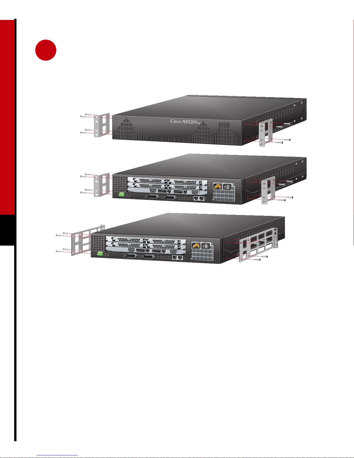
2 Install the Universal Access Server
Front panel forward
Rear panel forward
Rear panel forward,
center-mount telco
2
H10335
Prepare the Chassis for
Step 1 Attach the brackets using one of the three
methods shown above.
Rack-Mounting
You can install the chassis in a rack or on a desktop.
For a desktop installation, proceed to the next
section, “Prepare the Chassis for Desktop Use.”
Note: Brackets are included. Screws are included
for attaching the brackets to the chassis, but not for
installing the chassis in a rack. You will need four
additional screws to install the chassis in a rack.
Step 2 Install the chassis in a rack.
Page 5

2 Install the Universal Access Server (continued)
Universal access server
Prepare the Chassis for
Desktop Use
Attachthe rubber feet beforeinstalling the chassison
a desktop.
Note: Rubber feet are included.
Step 1 Locate the rubber feet on the black
adhesive strip that shipped with the
chassis.
Step 2 Place the access server upside-down on a
flat, smooth surface.
3
chassis bottom
Step 3 Peel off the rubber feet from the black
adhesive strip and place them
adhesive-side down on the dotted circles
at each corner of the chassis bottom.
Step 4 Place the access server right-side up on a
flat, smooth, secure surface.
Caution Do not place anything that
weighs more than 10 lb (4.5 kg) on top of
theaccess server. Excessive weight placedon
top of the chassis could damage it.
Page 6

2 Install the Universal Access Server (continued)
Ethernet AUI port (DB-15)
H10344
Ethernet
transceiver
8
7
1
Universal access server
10BaseT hub
4
Straight-through
10BaseT cable
Connect the Ethernet Port for
10BaseT Ethernet LAN Access
You can connect the access server to a 10BaseT or
thick Ethernet network. For a thick Ethernet
connection, proceed to the next section, “Connect
the Ethernet Port for Thick Ethernet LAN Access.”
You will need an Ethernet transceiver and cable to
connect the access server to a 10BaseT hub.
Note: The cable, transceiver, and hub are not
included.
Step 1 Connect an Ethernet transceiver to the
port labeled AUI on the rear panel of the
access server.
Step 2 Connect an Ethernet cable to the Ethernet
transceiver.
Step 3 Connect the other end of the Ethernet
cable to a 10BaseT hub.
Note: The Ethernet ports on the access server and
the hub must have the same baseband.
Page 7

2 Install the Universal Access Server (continued)
Ethernet AUI port (DB-15)
Universal access server
Ethernet hub
H10342
Ethernet AUI cable
Connect the Ethernet Port for
Thick Ethernet LAN Access
You will need an Ethernet AUI cable to connect the
access server to a hub.
Note: The cable and hub are not included.
5
Step 1 Connect your Ethernet AUI cable to the
port labeled AUI on the rear panel of the
access server.
Step 2 Connect the other end of the Ethernet
cable to an Ethernet hub.
Page 8

2 Install the Universal Access Server (continued)
H10337
T1/PRI card
T1/PRI
port 0 (RJ-45)
Straight-through
RJ-48C-to-RJ-48C cable
6
T1/PRI
port 1 (RJ-45)
RJ-48C jack
Connect the Dual T1/PRI Card
for WAN Access
You can connect the access server to a dual T1 or
E1/PRI card for WAN access. If you have a dual
E1/PRI card, go to the next section, “Connect the
Dual E1/PRI Card for WAN Access.”
You will need two straight-through
RJ-48C-to-RJ-48C cables to connect the dual
T1/PRI card to a WAN.
Universal access server
Step 1 Connect one end of the straight-through
RJ-48C-to-RJ-48C cable to the port
labeled Port 0 on the rear panel of the
access server.
Step 2 Connect the other end of the cable to an
RJ-48C jack.
Step 3 Repeats steps 1 and 2 to connect a second
cable to the port labeled Port 1.
Note: RJ-48C-to-RJ-48C cables are not included.
Page 9

2 Install the Universal Access Server (continued)
H10338
E1/PRI
port 1 (DB-15)
E1/PRI
port 0 (DB-15)
E1 cable
E1/PRI card
Connect the Dual E1/PRI Card
for WAN Access
You will need two E1 cables to connect the dual
E1/PRI card to a WAN.
Note: E1cablesand E1 networks terminating units
are not included.
Universal access server
E1 networks terminating unit
DB-15, Twinax,
RJ-45, or
BNC connector
Step 1 Connect one end of the E1 cable to the
portlabeled Port 0 onthe rear panel ofthe
access server.
Step 2 Connect the other end of the cable to an
E1 networks terminating unit.
Step 3 Repeats steps 1 and 2 to connect a second
cable to the port labeled Port 1.
7
Page 10

2 Install the Universal Access Server (continued)
H10339
Synchronous serial
port (DB-60)
Serial
transition
cable
Universal access server
8
EIA/TIA-232, EIA/TIA-449, V.35,
X.21, or EIA-530 connector
Connect the Synchronous
Step 1 Connect one end of a serial transition
cable to the port labeled Serial.
Serial Port for WAN Access
You will need two CSU/DSUs or modems and two
serial transition cables to connect the synchronous
serial ports to a WAN.
Step 2 Connect the other end of the cable to a
CSU/DSU or other DCE (such as a
modem).
Note: CSU/DSUs and serial transition cables are
not included.
Page 11

2 Install the Universal Access Server (continued)
Universal access server
H10340
Console port (RJ-45)
RJ-45-to-RJ-45
rollover cable
(labeled CONSOLE)
Connect to a Console for Local
Administrative Access
You will need an RJ-45-to-RJ-45 rollover cable and
a terminal adapter (RJ-45-to-DB-9 or
RJ-45-to-DB-25) to connect a console. These cables
and adapters are included. Take these steps:
PC
(laptop)
9
RJ-45-to-DB-9 or
RJ-45-to-DB-25 adapter
(labeled TERMINAL)
Step 2 Connect one end of the RJ-45-to-RJ-45
rollover cable to the adapter.
Step 3 Connect the other end of the
RJ-45-to-RJ-45 rollover cable to the port
labeled CONSOLE on the rear panel of
the access server.
Step 1 Connect one of the adapters, labeled
TERMINAL, tothe communications port
(usually labeled COM) on your
PC or terminal. (This communications
port is also known as a console.)
Step 4 Configure your PC terminal emulation
software or terminal for 9600 baud, 8
data bits, no parity, and 1 stop bit.
Page 12

2 Install the Universal Access Server (continued)
H10341
10
Auxiliary port (RJ-45)
RJ-45-to-RJ-45
rollover cable
(labeled AUX)
Connect a Modem for Remote
Administrative Access
(Optional)
To configure the access server from a remote
location, you will need an RJ-45-to-RJ-45 rollover
cable and a modem adapter (RJ-45-to-DB-25) to
connect a modem.
If you will not be using a modem to configure the
access server remotely,skip this procedure and go to
the next page.
Universal access server
Modem
RJ-45-to-DB-25 adapter
(labeled MODEM)
Note: The cable and adapter are included. The
modem is not included.
Step 1 Connect the adapter labeled MODEM to
your modem.
Step 2 Connect the RJ-45-to-RJ-45 rollover
cable to the adapter.
Step 3 Connect the other end of the
RJ-45-to-RJ-45 rollover cable to the port
labeled AUX on the rear panel of the
access server.
Page 13

2 Install the Universal Access Server (continued)
H10343
To power
outlet
Connect a Power Cable and
PowerontheUniversalAccess
Server
Step 1 Connect one end of the power cord to the
power connector on the rear panel of the
access server.
Universal access server
Power
switch
11
Caution kIt may take several minutes for
the startup messages to stop. Do not press
any keys until you see the following
message:
Would you like to enter the initial
configuration dialog? [yes]:
Step 2 Connect the other end of the power cord
to the power outlet.
Step 3 PowerON theaccess server. Messageswill
begin to appear on your console screen.
While you are waiting for this message to
appear, proceed to Section 3 .
Page 14

3 Configure the Universal Access Server
Use any of the following options for configuring your universal access server:
• Cisco Fast Step software
• Cisco IOS Release setup script
• Command line interface
The option you select depends on how you want to configure your universal access server. Use the information
on this page to help you decide which option to select.
Using Cisco Fast Step Software
Cisco Fast Step is a setup utility with a graphical user interface. It provides easy, step-by-step instructions for
setting up some of the most commonly used options available on the Cisco AS5200 universal access server. Use
Cisco Fast Step to configure your access server with the following options:
• Protocols and services (IP, IPX, and NetBEUI)
12
• LAN or WAN topology of 10BaseT, 10/100BaseT, and serial ports
• Controller settings (PRI or channelized T1/E1 interfaces)
• WAN encapsulation settings (Frame Relay and HDLC)
• LAN or WAN side IP or IPX settings
• Dial-in side IP or IPX settings
• IP address pools or DHCP server settings for dial-in users
• Access server security and security server settings
• Routing protocol settings including default and user defined (static) routes
Using Other Options
For all other configurations, use the Cisco IOS Release setup script or the command line interface. Refer to the
Cisco AS5200 Universal Access Server Software Configuration Guide for detailed instructions on using the
command line interface to configure your Cisco AS5200 universal access server.
Page 15

3 Configure the Universal Access Server (continued)
12
93
Install and Run Cisco Fast Step
1
2
Timesaver Use Appendix A to help you gather the appropriate information before you begin to
configure the access server using the setup script.
6
InserttheCisco Fast Step CD-ROM (attachedto the inside back coverofthis guide) into the CD-ROMdrive
of the local PC you connected in Section 2 .
The Fast Step install program starts Setup.exe automatically. If it does not, use the following steps to start
the Fast Step program:
(a) Double-click the My Computer icon on your computer desktop.
(b) Double-click the CD icon.
(c) Double-click the Setup.exe icon.
The install program prompts you for the information it needs to install Cisco Fast Step, then copies the
software to your hard drive.
Configure the Universal Access Server
Once installed,theCisco Fast Step setup program starts automatically. Follow the onscreen instructions to guide
you through configuring and testing the universal access server.
13
Page 16

14
A Gather Configuration Information
Use this appendix to note the information you may need for configurating your universal access server. You can
get this information from your network administrator.
Item Ask Your Network Administrator Enter the Information in This Column
1
2
3
4
5
What do you want to name the access server (to
distinguish it from other Cisco devices on your network)?
What do you want the encrypted enable secret password
to be?
What do you want the nonencrypted enable password to
be?
What do you want the password for remote console
access to be? This is referred to as the virtual terminal
password.
Do you want to configure:
SNMP? If so,
— What is the public (read-only) community string?
— What is the private (read-write) community string?
LAT?
AppleTalk? If so,
— AppleTalk multizone networks?
— What are the AppleTalk zone names?
— What are the AppleTalk network numbers?
DECNet?
IP?
IGRP routing? If so,
— What is the IGRP autonomous system number?
CLNS?
IPX? If so,
— What are the IPX network numbers?
VINES?
XNS?
Apollo?
Bridging?
Page 17

A Gather Configuration Information (continued)
Item Ask Your Network Administrator Enter the Information in This Column
6
7
8
9
10
11
12
13
14
The following information is required for channelized T1 or E1 configurations:
If you are configuring asynchronous interfaces, what
is the starting address for the IP local pool?
What is the ending address for the IP local pool?
What is the IP address for the Ethernet 0 interface?
How many bits are in the subnet mask?
What is the IP address for the Serial 0 interface?
How many bits are in the subnet mask?
What is the IP address for the Serial 1 interface?
How many bits are in the subnet mask?
What is your telco ISDN switch type?
Item Ask Your Network Administrator Enter the Information in This Column
15
16
17
What is your telco signaling type?
What is your telco framing type?
What is your telco line coding type?
15
Page 18

16
Page 19

17
Page 20

Corporate Headquarters
Cisco Systems, Inc.
170 West Tasman Drive
San Jose, CA 95134-1706
USA
http://www.cisco.com
Tel: 408 526-4000
800 553-NETS (6387)
Fax: 408 526-4100
European Headquarters
Cisco Systems Europe s.a.r.l.
Parc Evolic, Batiment L1/L2
16 Avenue du Quebec
Villebon, BP 706
91961 Courtaboeuf Cedex
France
http://www-europe.cisco.com
Tel: 33 1 69 18 61 00
Americas
Headquarters
Cisco Systems, Inc.
170 West Tasman Drive
San Jose, CA 95134-1706
USA
http://www.cisco.com
Tel: 408 526-7660
Fax: 408 527-0883
Asia Headquarters
Nihon Cisco Systems K.K.
Fuji Building, 9th floor
3-2-3 Marunouchi
Chiyoda-ku, Tokyo 100
Japan
http://www.cisco.com
Tel: 81 3 5219 6250
Fax: 81 3 5219 6001
Fax: 33 1 69 28 83 26
Cisco Systems has more than 200 offices in the following countries. Addresses, phone numbers, and fax numbers are listed on the
Cisco Connection Online Web site at http://www.cisco.com/offices.
Argentina • Australia • Austria • Belgium • Brazil • Canada • Chile • China • Colombia • Costa Rica • Croatia • Czech Republic • Denmark • Dubai, UAE
Finland • France • Germany • Greece • Hong Kong • Hungary • India • Indonesia • Ireland • Israel • Italy • Japan • Korea • Luxembourg • Malaysia
Mexico • The Netherlands • New Zealand • Norway • Peru • Philippines • Poland • Portugal • Puerto Rico • Romania • Russia • Saudi Arabia • Singapore
Slovakia • Slovenia • South Africa • Spain • Sweden • Switzerland • Taiwan • Thailand • Turkey • Ukraine • United Kingdom • United States •
Venezuela
Copyright © 1998-1999, Cisco Systems, Inc. All rights reserved. Access Registrar, AccessPath, Any to Any, AtmDirector, CCDA, CCDE, CCDP, CCIE, CCNA, CCNP, CCSI, CD-PAC, Centri, Cisco Certified
Internetwork Expert logo, CiscoLink, the Cisco Management Connection logo, the Cisco NetWorks logo, the Cisco Powered Network logo, Cisco Systems Capital, the Cisco Systems Capital logo, the Cisco
Technologies logo, ControlStream, Fast Step, FireRunner, Gigastack, IGX, JumpStart, Kernel Proxy, LoopRunner, MGX, Natural Network Viewer, NetSonar, Network Registrar, Packet, PIX, Point and Click
Internetworking, Policy Builder, Precept, RouteStream, Secure Script, SMARTnet, SpeedRunner, Stratm, StreamView, The Cell, TrafficDirector, TransPath, ViewRunner, VirtualStream, VlanDirector, Workgroup
Director,andWorkgroup Stack are trademarks; Changing the Way WeWork, Live, Play, and Learn, Empowering the Internet Generation, The Internet Economy, and The New Internet Economy are service marks;
and BPX, Catalyst, Cisco, Cisco IOS, the Cisco IOS logo, Cisco Systems, the Cisco Systems logo, the Cisco Systems Cisco Press logo, Enterprise/Solver,EtherChannel,FastHub,ForeSight,FragmentFree,IOS,IP/TV,
IPX, LightStream, LightSwitch, MICA, NetRanger,Phase/IP, Registrar,StrataSphere,andStrataViewPlusareregisteredtrademarksofCiscoSystems,Inc.intheU.S.andcertainothercountries.Allothertrademarks
mentioned in this document are the property of their respective owners. (9902b R)
Printed in the USA on recycled paper containing 10% postconsumer waste.
DOC-AS5200-QSG=
78-4311-03
 Loading...