

Page 1
Doc. No.
78-4309-01
Replacing the Power Supply in Cisco AS5200
Universal Access Servers
Product Numbers: AS5200-PWR-AC= , AS5200-PWR-DC=
This document describes how to replace the internal power supply and includes the following
sections:
• Safety Recommendations, page 1
• Required Tools and Equipment, page 4
• Removing the Chassis Cover, page 5
• Removing the Power Supply, page 7
• Installing the Power Supply, page 10
• Closing the Chassis Cover, page 13
• Cisco Connection Online, page 14
Safety Recommendations
Follow these guidelines to ensure general safety:
• Keep the chassis area clear and dust-free during and after installation.
• Put the removed chassis cover in a safe place.
• Keep tools away from walk areas where you or others could fall over them.
• Do not wear loose clothing that could get caught in the chassis. Fasten your tie or scarf and roll
up your sleeves.
• Wear safety glasses when working under any conditions that might be hazardous to your eyes.
• Do not perform any action that creates a potential hazard to people or makes the equipment
unsafe.
Corporate Headquarters
Cisco Systems, Inc.
170 West Tasman Drive
San Jose, CA 95134-1706
USA
Copyright © 1997
Cisco Systems, Inc.
All rights reserved.
1
Page 2

Safety Recommendations
Safety Warnings
Safety warnings appearthroughout this publicationin procedures that,if performedincorrectly,may
harm you. A warning symbol precedes each safety warning.
Warning Thiswarning symbolmeans danger. Youare in a situation that could cause bodily injury.
Before you work on any equipment, be aware of the hazards involved with electrical circuitry and
be familiarwith standard practices for preventingaccidents. To seetranslations of thewarnings that
appear in thispublication, refer to the RegulatoryComplianceand Safety Information document that
accompanied this device.
Waarschuwing Dit waarschuwingssymbool betekent gevaar. U verkeert in een situatie die
lichamelijk letsel kan veroorzaken. Voordatu aanenige apparatuurgaat werken,dient u zich bewust
te zijn van de bij elektrische schakelingen betrokken risico's en dient u op de hoogte te zijn van
standaard maatregelen om ongelukken te voorkomen. Voor vertalingen van de waarschuwingen die
in deze publicatie verschijnen, kunt u hetdocument RegulatoryCompliance and Safety Information
(Informatie over naleving van veiligheids- en andere voorschriften) raadplegen dat bij dit toestel is
ingesloten.
Varoitus Tämävaroitusmerkkimerkitsee vaaraa. Olet tilanteessa,jokavoijohtaa ruumiinvammaan.
Ennen kuin työskentelet minkään laitteiston parissa, ota selvää sähkökytkentöihin liittyvistä
vaaroista ja tavanomaisista onnettomuuksien ehkäisykeinoista. Tässä julkaisussa esiintyvien
varoitusten käännökset löydät laitteen mukana olevasta Regulatory Compliance and Safety
Information -kirjasesta (määräysten noudattaminen ja tietoa turvallisuudesta).
Attention Ce symbole d'avertissement indique un danger. Vous vous trouvez dans une situation
pouvant causer des blessures ou des dommages corporels. Avant de travailler sur un équipement,
soyez conscient des dangers posés par les circuits électriques et familiarisez-vous avec les
procédures couramment utilisées pour éviter les accidents. Pour prendre connaissance des
traductions d’avertissements figurant dans cette publication, consultez le document Regulatory
Compliance and Safety Information (Conformité aux règlements et consignes de sécurité) qui
accompagne cet appareil.
Warnung Dieses Warnsymbol bedeutet Gefahr. Sie befinden sich in einer Situation, die zu einer
Körperverletzungführen könnte.BevorSie mitder Arbeit an irgendeinem Gerätbeginnen, seien Sie
sich der mit elektrischen Stromkreisen verbundenen Gefahren und der Standardpraktiken zur
Vermeidung von Unfällen bewußt. Übersetzungen der in dieser Veröffentlichung enthaltenen
Warnhinweise finden Sie im Dokument Regulatory Compliance and Safety Information
(Informationen zu behördlichen Vorschriften und Sicherheit), das zusammen mit diesem Gerät
geliefert wurde.
Avvertenza Questo simbolo di avvertenza indica un pericolo. La situazione potrebbe causare
infortuni alle persone. Prima di lavorare su qualsiasi apparecchiatura, occorre conoscere i pericoli
relativiai circuiti elettriciedessere al correntedelle pratiche standardperla prevenzione di incidenti.
La traduzione delle avvertenze riportate in questa pubblicazione si trova nel documento Regulatory
Compliance and Safety Information (Conformità alle norme e informazioni sulla sicurezza) che
accompagna questo dispositivo.
Advarsel Dette varselsymbolet betyr fare. Du befinner deg i en situasjon som kan føre til
personskade. Før du utfører arbeid på utstyr, må du vare oppmerksom på de faremomentene som
elektriskekretser innebærer, samt gjøredeg kjent medvanlig praksis nårdet gjelder åunngå ulykker.
Hvis du vil se oversettelser av de advarslene som finnes i denne publikasjonen, kan du se i
dokumentet Regulatory Compliance and Safety Information (Overholdelse av forskrifter og
sikkerhetsinformasjon) som ble levert med denne enheten.
Aviso Este símbolode avisoindica perigo. Encontra-se numa situação que lhe poderá causardanos
físicos. Antes de começar a trabalhar com qualquer equipamento, familiarize-se com os perigos
relacionados com circuitos eléctricos, e com quaisquer práticas comuns que possam prevenir
2 Replacing the Power Supply in Cisco AS5200 Universal Access Servers
Page 3
possíveis acidentes. Para ver as traduções dos avisos que constam desta publicação, consulte o
documento Regulatory Compliance and Safety Information (Informação de Segurança e
Disposições Reguladoras) que acompanha este dispositivo.
¡Advertencia! Este símbolo de aviso significa peligro. Existe riesgo para su integridad física.
Antes de manipular cualquier equipo, considerar los riesgos que entraña la corriente eléctrica y
familiarizarse con los procedimientos estándar de prevenciónde accidentes. Paraver una traducción
de las advertencias que aparecen en esta publicación, consultar el documento titulado Regulatory
Compliance and Safety Information (Información sobre seguridad y conformidad con las
disposiciones reglamentarias) que se acompaña con este dispositivo.
Varning! Denna varningssymbol signalerar fara. Du befinner dig i en situation som kan leda till
personskada. Innan du utför arbete på någon utrustning måste du vara medveten om farorna med
elkretsar och känna till vanligt förfarande för att förebygga skador. Se förklaringar av de varningar
som förkommer i denna publikation i dokumentet Regulatory Compliance and Safety Information
(Efterrättelse av föreskrifter och säkerhetsinformation), vilket medföljer denna anordning.
Safety with Electricity
Follow these guidelines when working on equipment powered by electricity:
• Locate the emergency power-OFF switch in the room in which you are working. Then, if an
electrical accident occurs, you can quickly shut the power OFF.
Safety Recommendations
Warning Read the installation instructions before you connect the system to its power source.
Warning Ultimate disposal of this product should be handled according to all national laws and
regulations.
Warning Only trained and qualified personnel should be allowed to install or replace this
equipment.
Warning To ensure your safety and the safety of others, be sure the power is OFF and the power
cord is unplugged before working on the router.
• Disconnect all power before doing the following:
— Installing or removing a chassis
— Working near power supplies
Warning Beforeworkingon equipment thatis connected topowerlines, remove jewelry (including
rings, necklaces, and watches).Metal objects will heat upwhen connected to power and ground and
can cause serious burns or weld the metal object to the terminals.
• Do not work alone if potentially hazardous conditions exist.
• Never assume that power is disconnected from a circuit. Always check.
Replacing the Power Supply in Cisco AS5200 Universal Access Servers 3
Page 4

Required Tools and Equipment
• Look carefully for possible hazards in your work area, such as moist floors, ungrounded power
extension cables, and missing safety grounds.
• If an electrical accident occurs, proceed as follows:
— Use caution; do not become a victim yourself.
— Turn OFF power to the system.
— Ifpossible, send anotherperson to getmedical aid. Otherwise,determine the conditionof the
victim and then call for help.
— Determine if the person needs rescue breathing or external cardiac compressions; then take
appropriate action.
Preventing Electrostatic Discharge Damage
Electrostatic discharge(ESD) can damage equipment and impair electrical circuitry. It occurs when
electronic printed circuit cards are improperly handled and can result in complete or intermittent
failures.Always follow ESD preventionprocedureswhen removingandreplacing cards. Ensure that
the chassis is electrically connected to earth ground. Wear an ESD-preventive wrist strap, ensuring
that it makes good skin contact. Connect the clip to an unpainted surface of the chassis frame to
safely channel unwanted ESD voltages to ground. To properly guard against ESD damage and
shocks, the wrist strap and cord must operate effectively. If no wrist strap is available, ground
yourself by touching the metal part of the chassis.
Caution For safety, periodically check the resistance value of the antistatic strap, which should be
between 1 and 10 megohms (Mohm).
Required Tools and Equipment
This kit includes the following items:
• An AC or DC power supply
• Power ratings labels
To install the power supply, you will also need the following tools and equipment (which are not
included):
• Cisco AS5200 access server
• Medium-size Phillips screwdriver
• ESD-preventive wrist strap
• Tie-wraps (optional)
• Antistatic bag (optional)
4 Replacing the Power Supply in Cisco AS5200 Universal Access Servers
Page 5
Removing the Chassis Cover
Warning Do not touch the power supply when the power cord is connected. For systems with a
power switch, line voltages are present within the power supply even when the power switch is off
and the power cord is connected. For systems without a power switch, line voltages are present
within the power supply when the power cord is connected.
Take these steps:
Step 1 Power OFF the access server.
Before working on a chassis or working near powersupplies, unplug the power cord on AC units;
disconnect the power at the circuit breaker on DC units.
Warning Before opening the chassis, disconnect the telephone-network cables to avoid contact
with telephone-network voltages.
Warning Do not work on the system or connect or disconnect cables during periods of lightning
activity.
Removing the Chassis Cover
Step 2 Remove all cables from the rear panel of the access server.
Step 3 Place the access server so that the front panel is facing you.
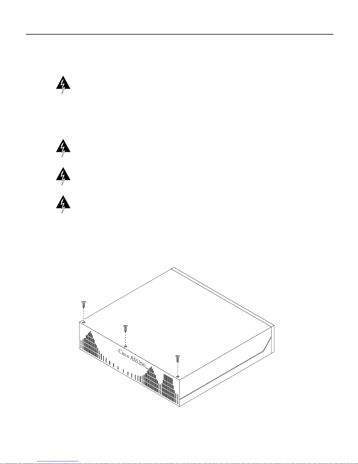
Step 4 Remove the three screws located on the top cover of the chassis.
Figure 1 Removing the Top Cover
H6254
Replacing the Power Supply in Cisco AS5200 Universal Access Servers 5
Page 6

Removing the Chassis Cover
Step 5 Lift up the front edge of the top cover a few inches. You might need to use a screwdriver
Figure 2 Lifting the Top Cover
to pry the top cover apart from the chassis bottom.
H6260
Step 6 Pull the top cover toward you until the metal tabs on the top cover separate from the
chassis bottom.
Figure 3 Separating the Top Cover from the Chassis Bottom
H6261
Step 7
Lift the top cover until it separates from the chassis bottom and set it aside.
6 Replacing the Power Supply in Cisco AS5200 Universal Access Servers
Page 7

Removing the Power Supply
Take these steps:
Step 1 Place the access server so that the rear panel is facing you.
Figure 4 Cisco AS5200 Access Server Rear Panel
Removing the Power Supply
H10144
Step 2
Removethe two mounting screwsthat secure thepowersupply to thechassis and setthem
aside.
Figure 5 Removing the Mounting Screws
Mounting
screws
Power
supply
Note Although the illustrations in this document show the AC power supply, the
procedures are the same for the DC power supply.
H8686
Step 3 Now turn the access server so that the front panel is facing you.
Replacing the Power Supply in Cisco AS5200 Universal Access Servers 7
Page 8

Removing the Power Supply
Step 4 Locate the two small two-pin connectors that power the fans. Grasp the two halves of
Figure 6 Disconnecting the Two-Pin Connectors
each connector firmly and pull them apart.If the tie-wraps get inyour way, cut them. But
be careful not to cut the wires. If the wires are cut, the fans will not operate.
Power supply
Step 5
Two, two-pin
connectors
to the fans
H10170
Locate the large rectangular 11-pin connector that connects the power supply to the
backplane. While pulling firmly, wiggle the connector until it disconnects from the
backplane. It may take some force to disconnect the connector.
8 Replacing the Power Supply in Cisco AS5200 Universal Access Servers
Page 9

Figure 7 Disconnecting the Power Connector
Power supply
11-pin
connector
Removing the Power Supply
Step 6
Slide the power supply slightly toward the front of the chassis. This disengages the
built-in hook that helps secure the power supply to the chassis.
Figure 8 Removing the Power Supply
Power supply
Hook
H10171
H10172
Step 7 Lift the power supply out of the chassis. If you want to preserve the power supply, put it
in an antistatic bag.
Replacing the Power Supply in Cisco AS5200 Universal Access Servers 9
Page 10

Installing the Power Supply
Installing the Power Supply
Take these steps:
Step 1 Place the access server so that the rear panel is facing you.
Step 2 Align the new power supply with the chassis cutout and the built-in hook. Then slide the
power supply toward you, making sure that the built-in hook engages.
Figure 9 Installing the Power Supply
Power supply
Power supply
hook
Chassis hook
H10173
10 Replacing the Power Supply in Cisco AS5200 Universal Access Servers
Page 11

Installing the Power Supply
Step 3 Connect the 11-pin connector to the backplane. Note the orientation of the connector
relative to the backplane.
Figure 10 Connecting the 11-Pin Connector to the Backplane
Power supply
11-pin
connector
H10179
Replacing the Power Supply in Cisco AS5200 Universal Access Servers 11
Page 12

Installing the Power Supply
Step 4 Connect the two small two-pin connectors used to power the fans.
Figure 11 Connecting the Two-Pin Connectors
Power supply
Two, two-pin
connectors
to the fans
Step 5
Reinstall the mounting screws into the screw holes on the rear panel.
Figure 12 Reinstalling the Mounting Screws
Mounting
screws
Power
supply
H8686
H10170
12 Replacing the Power Supply in Cisco AS5200 Universal Access Servers
Page 13

Closing the Chassis Cover
Step 6 If you installed a different type of powersupply (ACor DC)than was originally installed
in the accessserver,place oneof the powerratings labelsthat came in the plasticbag with
the documentation directly over the power ratings information on the rear panel. For
example, if the original chassis came with an AC power supply and you replaced it with
a DC powersupply,place theDC powerratings label over the ratings stamped on the rear
panel of the chassis. This will ensure that the correct power ratings information appears
on the rear panel.
Figure 13 Attaching the Power Ratings Label
Label
Closing the Chassis Cover
Refer to Figure 14 and take these steps:
Step 1 Place the chassis bottom so that the front panel is facing you.
Step 2 Hold the top coveroverthe chassis bottom, and align the chassis and topcover tabs at the
top rear of the chassis.
INPUT 100-240V~ 50/60HZ 1.5 - 3.0A
H10169
Replacing the Power Supply in Cisco AS5200 Universal Access Servers 13
Page 14

Cisco Connection Online
Figure 14 Replacing the Chassis Cover
H6254
Step 3
Push the top cover toward the chassis back panel, and ensure the following:
• The top cover tabs fit under the chassis back panel so that they are not exposed.
• The chassis tabson the topof thechassis back panelfit underthe top coversothat they
Step 4 Lower the front of the top cover to close the chassis, and ensure the following:
• The top cover side tabs fit under the chassis side panels so that they are not exposed.
• The chassis tabs fit under the top cover side panels so that they are not exposed.
Step 5 Reinstall the three screws that secure the chassis cover to the chassis bottom.
Step 6 Reinstall the chassis in a rack or on a tabletop.
Step 7 Reconnect all cables.
Step 8 Remove your ESD-preventive wrist strap.
The concludes the procedure for replacing the power supply.
Cisco Connection Online
CiscoConnection Online (CCO)is Cisco Systems’primary,real-timesupport channel. Maintenance
customers and partners can self-register on CCO to obtain additional information and services.
Available 24 hours a day, 7 days a week, CCO provides a wealth of standard and value-added
services to Cisco’s customers and business partners. CCO services include product information,
product documentation, software updates, release notes, technical tips, the Bug Navigator,
configuration notes, brochures, descriptions of service offerings, and download access to public and
authorized files.
are not exposed.
14 Replacing the Power Supply in Cisco AS5200 Universal Access Servers
Page 15

Cisco Connection Online
CCO serves a wide variety of users through two interfaces that are updated and enhanced
simultaneously: a character-based version and a multimedia version that resides on the WorldWide
Web (WWW). The character-based CCO supports Zmodem, Kermit, Xmodem, FTP, and Internet
e-mail,and itisexcellent for quickaccess to informationoverlowerbandwidths. The WWWversion
of CCO providesrichly formatted documentswith photographs,figures, graphics, andvideo, aswell
as hyperlinks to related information.
You can access CCO in the following ways:
• WWW: http://www.cisco.com
• WWW: http://www-europe.cisco.com
• WWW: http://www-china.cisco.com
• Telnet: cco.cisco.com
• Modem: From North America, 408 526-8070; from Europe, 33 1 64 46 40 82. Use the
following terminal settings: VT100 emulation; databits: 8; parity: none; stop bits: 1; and
connection rates up to 28.8 kbps.
For a copy of CCO’s Frequently Asked Questions (FAQ), contact cco-help@cisco.com. For
additional information, contact cco-team@cisco.com.
Note If you are a network administrator and need personal technical assistance with a Cisco
product that is under warranty or covered by a maintenance contract, contact Cisco’s Technical
Assistance Center (TAC) at 800 553-2447, 408 526-7209, or tac@cisco.com. To obtain general
information about Cisco Systems, Cisco products, or upgrades, contact 800 553-6387,
408 526-7208, or cs-rep@cisco.com.
Use this document with the Cisco AS5200 Universal Access Server Hardware Installation Guide and Regulatory Compliance and Safety Information publications.
AtmDirector, AutoConnect, AutoRoute, AXIS, BPX, Catalyst, CD-PAC, CiscoAdvantage, CiscoFusion, Cisco IOS, the Cisco IOS logo, CiscoLink, CiscoPro, the CiscoPro logo,
CiscoRemote, the CiscoRemote logo, CiscoSecure, Cisco Systems, CiscoView, CiscoVision, CiscoWorks, ClickStart, ControlStream, EdgeConnect, EtherChannel, FairShare, FastCell,
FastForward, FastManager, FastMate, FastPADlmp, FastPADmicro, FastPADmp, FragmentFree, FrameClass, Fulcrum INS, IGX, Impact, Internet Junction, JumpStart, LAN
Enterprise, LAN
SMARTnet,StrataSphere, StrataSphere BILLder, StrataSphere Connection Manager, StrataSphere Modeler,StrataSphere Optimizer,Stratm, StrataViewPlus, StreamView, SwitchProbe,
SwitchVision, SwitchWare, SynchroniCD, The Cell, The FastPacket Company, TokenSwitch, TrafficDirector, Virtual EtherSwitch, VirtualStream, VlanDirector, WebClusters, WNIC,
Workgroup Director, Workgroup Stack, and XCI are trademarks; Access by Cisco, Bringing the Power of Internetworking to Everyone, Enter the Net with MultiNet, and The Network
Works. NoExcuses. are service marks; and Cisco, the Cisco Systems logo, CollisionFree, Combinet, EtherSwitch, FastHub, FastLink, FastNIC, FastPacket, FastPAD, FastSwitch,
ForeSight, Grand, Grand Junction, Grand Junction Networks, the Grand Junction Networks logo, HSSI, IGRP, IPX, Kalpana, theKalpana logo, LightStream, MultiNet, MultiWare,
OptiClass, Personal Ethernet, Phase/IP, RPS, StrataCom, TGV, the TGV logo, and UniverCD are registered trademarks of Cisco Systems, Inc. All other trademarks, service marks,
registered trademarks, or registered service marks mentioned in this document are the property of their respective owners.
Copyright © 1997, Cisco Systems, Inc.
All rights reserved. Printed in USA.
9611R
2
LAN Remote Office, LightSwitch, MICA, NetBeyond, NetFlow, Newport Systems Solutions, Packet, PIX, Point and Click Internetworking, RouteStream, Secure/IP,
2
LAN
Replacing the Power Supply in Cisco AS5200 Universal Access Servers 15
Page 16

Cisco Connection Online
16 Replacing the Power Supply in Cisco AS5200 Universal Access Servers
 Loading...