

Page 1

Cisco AS3005 Series Media Processor
Operation Manual
v 1.3.2
Americas Headquarters
Cisco Systems, Inc.
175 West Tasman Drive
San Jose, CA 95134-1706
USA
1 408 526 7209
1 800 553 2447
2402-0130-000B
Page 2

Notices
Trademark Acknowledgments
Cisco and the Cisco logo are trademarks or registered trademarks of Cisco and/or its
affiliates in the U.S. and other countries. A listing of Cisco's trademarks can be found at
www.cisco.com/go/trademarks.
Third party trademarks mentioned are the property of their respective owners.
The use of the word partner does not imply a partnership relationship between Cisco
and any other company. (1009R)
Publication Disclaimer
Cisco Systems, Inc. assumes no responsibility for errors or omissions that may appear
in this publication. We reserve the right to change this publication at any time without
notice. This document is not to be construed as conferring by implication, estoppel, or
otherwise any license or right under any copyright or patent, whether or not the use of
any information in this document employs an invention claimed in any existing or later
issued patent.
Copyright
© 2011 Cisco and/or its affiliates. All rights reserved. Printed in the United States
of America.
Information in this publication is subject to change without notice. No part of this
publication may be reproduced or transmitted in any form, by photocopy, microfilm,
xerography, or any other means, or incorporated into any information retrieval system,
electronic or mechanical, for any purpose, without the express permission of Cisco
Systems, Inc.
The Inlet Technologies Spinnaker S3000/S5000 Series has been renamed as the Cisco S3000/S5000 Series
Media Processors. Beginning June 15, 2011, you will begin to see the Cisco name and company logo, along with
the new product name on the hardware, software, documentation and packaging. During this transition process
you may see both Inlet Technologies and Cisco brands and former product names. These products meet the
same high standards and quality that both Inlet Technologies and Cisco are known for in the industry.
Page 3

Table of Contents
SAFETY PRECAUTIONS ................................................................................................................... I
Important Safety Information .............................................................................................. i
Unpacking ............................................................................................................................. i
Power and Cables ................................................................................................................ i
Choosing the Installation Site ........................................................................................... ii
Placement of Equipment .................................................................................................... ii
Enclosure ............................................................................................................................ iii
Modifications ...................................................................................................................... iii
EMC ..................................................................................................................................... iii
Compliance ......................................................................................................................... iv
1 INTRODUCTION ....................................................................................................................... 1
2 GETTING STARTED ................................................................................................................. 3
Installing Connections ............................................................................................................ 3
Digital Video and Audio ...................................................................................................... 3
Analog Video and Audio .................................................................................................... 4
Video and Audio .................................................................................................................. 5
Ethernet Ports ..................................................................................................................... 5
Power Cable ........................................................................................................................ 6
Powering Up ............................................................................................................................. 6
Setting IP Addresses ............................................................................................................... 6
3 WEB INTERFACE ..................................................................................................................... 8
Remote Management via the Web .......................................................................................... 8
Opening the Interface ......................................................................................................... 8
Logging In ............................................................................................................................ 9
Summary Page .................................................................................................................. 12
Presets Page ..................................................................................................................... 15
Video Page ......................................................................................................................... 16
Audio Page ........................................................................................................................ 26
Output Page ....................................................................................................................... 27
System Page ...................................................................................................................... 32
Starting/Stopping Encodes .............................................................................................. 39
Session Timeouts ............................................................................................................. 39
4 FRONT PANEL CONTROLS .................................................................................................. 40
Front Panel Menu Layout ...................................................................................................... 40
Changing values via the Front Panel Controls ................................................................... 43
Front Panel Control Status ................................................................................................... 44
APPENDIX A: TECHNICAL GUIDE ................................................................................................ 45
Understanding VC-1 .............................................................................................................. 45
VC-1 codec specification ................................................................................................. 45
MIB for SNMP ......................................................................................................................... 46
Page 4

APPENDIX B: MANAGING USER ACCOUNTS ............................................................................ 50
APPENDIX C: TROUBLESHOOTING ............................................................................................ 51
Video Check Tool .............................................................................................................. 51
Resolve Security Certificate Warning ............................................................................. 51
Recovery Page .................................................................................................................. 54
APPENDIX D: SPECIFICATIONS ................................................................................................... 55
Inputs ...................................................................................................................................... 55
Video .................................................................................................................................. 55
Audio .................................................................................................................................. 55
Codecs .................................................................................................................................... 55
Output ..................................................................................................................................... 55
Local ................................................................................................................................... 55
IP ..................................................................................................................................... 55
Control .................................................................................................................................... 56
Additional Features .......................................................................................................... 56
Processing .............................................................................................................................. 56
Pre-processing .................................................................................................................. 56
Encoding ............................................................................................................................ 56
Physical and Power ............................................................................................................... 56
Dimensions ........................................................................................................................ 56
Power ................................................................................................................................. 57
Certifications .......................................................................................................................... 57
Operating Conditions ............................................................................................................ 57
Ambient Temperature ....................................................................................................... 57
Relative humidity .............................................................................................................. 57
INDEX ................................................................................................................................. 58
LIMITED PRODUCT WARRANTY .................................................................................................. 59
Page 5

SSAAFFEETTYY PPRREECCAAUUTTIIOONNSS
Important Safety Information
Protect yourself from electric shock and protect your equipment from damage. Read
these safety and operating instructions before operating this equipment, and retain them
for future reference. Follow all operating instructions while using the equipment, paying
attention to all warnings and cautions in this guide.
Unpacking
The Cisco Media Processor unit ships with the following items for installation and use.
If any of these items are not received, contact Inlet support at support@inlethd.com.
AC Power Cable
Mounting Hardware Kit
Breakout Cable Adapter(s). One cable is included for all units except S3200
units, which include two cables.
Operation Manual
Power and Cables
WARNING: Electric shock hazard.
To reduce the risk of electric shock, perform only the
instructions that are included in this operation manual.
Refer all servicing to qualified service personnel only.
WARNING:
Electric shock can cause personal injury or even death. Avoid direct contact with
dangerous voltages at all times.
You must properly ground this Class I product. Do not violate the protective grounding
by using an extension cable, power cable, or autotransformer without a protective
ground conductor. The protective ground connection is essential to safe operation and
must be verified before connecting the power supply.
This product plugs into a socket outlet. This outlet should be easily accessible and the
cable and plug should not be walked on or stressed.
i
Page 6

Before servicing this product, always disconnect the power cable by pulling the plug, not
the cable itself. Units equipped with redundant power supplies must have both supplies
disconnected before servicing.
Choosing the Installation Site
The installation site for your Cisco Media Processor must meet the following
requirements:
Protective ground: The protective ground lead of the site’s electrical installation
must comply with local and national requirements.
Environmental condition: The site should be ventilated, dry, and clean, with no
risk to the equipment of contact with water.
Placement of Equipment
Install this equipment in a restricted access location. Make sure the mounting surface
or rack is stable, can support the size and weight of this equipment and is appropriately
anchored according to manufacturer’s specifications.
Ventilation and Temperature
This equipment has openings for ventilation to protect it from overheating. To ensure
safe operation and equipment reliability, do not block or cover any of the ventilation
openings. If this product is mounted on a rack, do not obstruct the cooling airflow
through the rack.
Do not install this equipment near any heat sources such as heat registers, radiators,
stoves, or other heat-producing equipment.
Rack Mounting
The rack should be placed on a stable surface, with any stabilizing devices already
installed prior to mounting equipment on the rack.
A closed or multi-unit rack assembly’s environment may have a greater operating
ambient temperature than the room ambient temperature. Ensure that the operating
ambient temperature complies with the maximum rated ambient temperature.
The Cisco Media Processor unit is mounted to the rack using the hardware provided in
the accessory kit. In server racks or cabinets four 10-32 x ½ inch size screws and #10
lock washers are used. For Telecom racks four 12-24 x ¾ inch size screws and #12
lock washers are used. The lock washers are placed between the Media Procesor unit
mounting ear and the screw head.
Cabling from the Media Procesor unit should be dressed to prevent blocking air exhaust
from the unit.
ii
Page 7
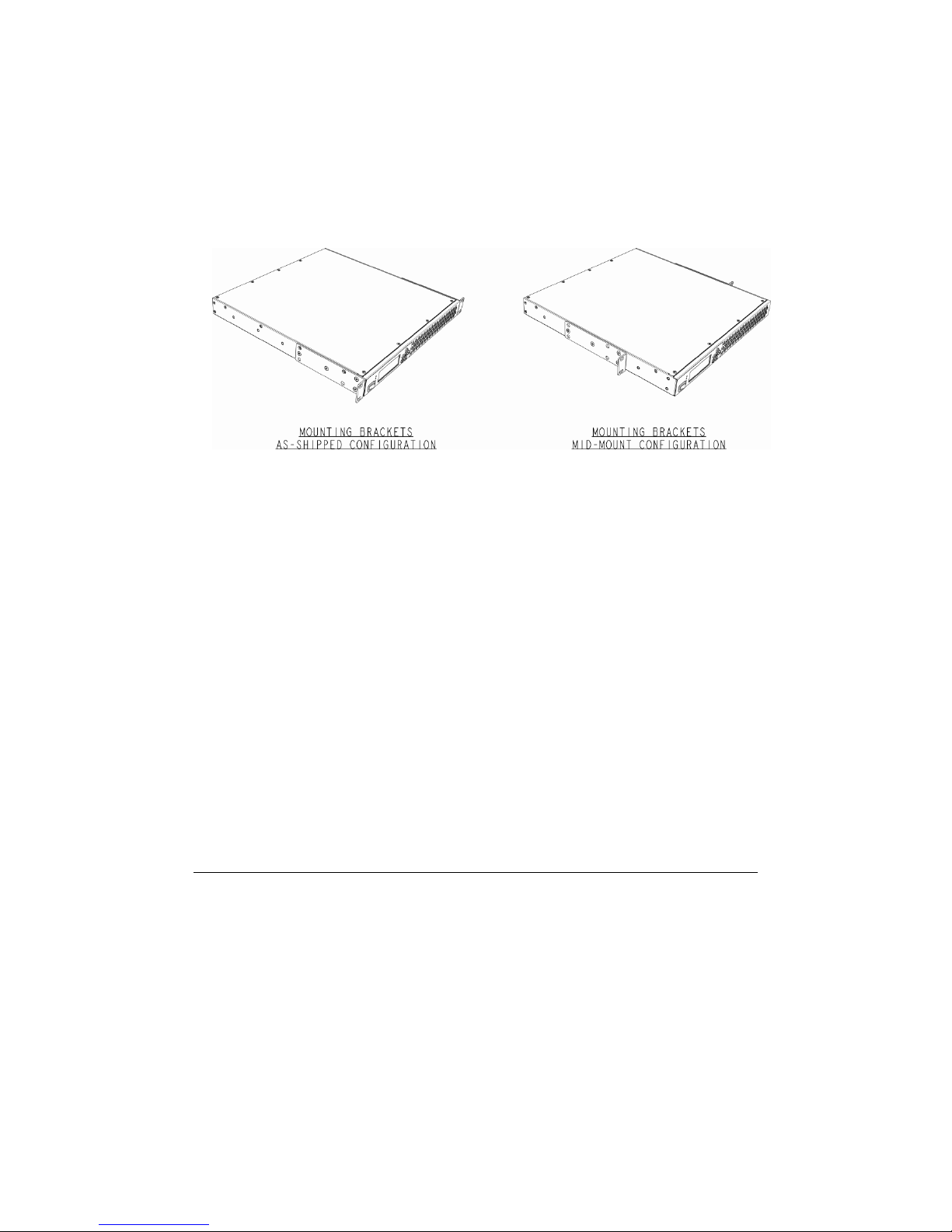
Instructions for Reconfiguring Rack Mounting Brackets for MidMounting:
1. Remove and retain the eight (8) screws securing the 2 rack mounting
brackets to the chassis side walls.
2. Slide both brackets back 5 inches (125mm) until all 4 countersunk holes in
each bracket align with 4 threaded holes in chassis side walls.
3. Reinstall the eight (8) screws through the 2 rack brackets and into the
threaded holes in the chassis side walls. Torque to 20 lbs-in (2.25 N-m).
Enclosure
Do not open the Media Procesor as this will void the product warranty. Do not allow
moisture or any objects to enter openings in the enclosure.
Modifications
Do not make any modifications to this equipment. Modifications may put people or
property at risk of injury or damage by potentially degrading the level of protection built
into the equipment.
EMC
Where this equipment is subject to USA FCC rules, the following statement applies:
FCC Statement
This equipment has been tested and found to comply with the limits for a Class A digital
device according to Part 15 of the FCC rules. These limits are designed to provide
reasonable protection against harmful interference when this equipment is operated in a
commercial environment.
This equipment generates, uses, and can radiate radio frequency energy and, if not
installed and used in accordance with this operations manual, may cause harmful
interference to radio communications. Operation of this equipment in a residential area
iii
Page 8

is likely to cause harmful interference in which case the user will be required to correct
the interference at his own expense.
Compliance
Electromagnetic Compatibility
FCC Part 15 Subpart B: This equipment has been tested and found to comply
with the limits for a Class A digital device, pursuant to Part 15 of the FCC
Rules.
CE marked: According to EMC directive 89/336/EEC and 93/68/EEC
(European standards EN 55 022, EN 55 024, En 61000-3-2 and EN 61000-3-
3).
Safety
cTUVus Certified to UL 60950-1:2003 and CAN/CSA-C22.2 No. 60950-1-03
CE marked: According to LVD directive 73/23/EEC and 93/68/EEC (European
standard EN 60950-1).
iv
Page 9

CISCO S3000/S5000 SERIES MEDIA PROCESSORS
1
IInnttrroodduuccttiioonn
Cisco Media Processor is a comprehensive advanced encoding solution that enables
service providers to reach new audiences through new media networks. This
professional-grade solution delivers best-in-class output quality for live media delivery
applications such as IPTV, broadband TV, Web streaming, government, education or
enterprise video.
Cisco Media Processor is a highly reliable, robust family of encoding solutions that
optimizes bandwidth and delivers unique capabilities to transform an IP network into a
true broadcast experience. It produces output in multiple resolutions for delivery to both
TV and PC-based devices through IPTV set top boxes and Internet gateways, providing
a broad reach of digital media to new subscribers.
Cisco Media Processor provides highly efficient device management capability through
its Web interface. Cisco Media Processor encoders are highly flexible and scalable,
supporting resolutions from Web to SD to HD. Cisco Media Processor provides core
encoding that is fully supported both today and in the future for enhancements and longterm support of service providers. Cisco Media Processor is available in three
configurations series to meet the price/performance needs of new media distribution.
There exist multiple products within a model series, such as the S3200 which is a dual
channel version of the S3000.
Media
Processor
S3000
Series
S5000
Series
S7000
Series
This manual contains information on getting started and operating the Cisco S3000 and
S5000 Series Media Processors. In addition to having more processing power, the
S5000 series is a superset of the S3000 series and contains additional features. Refer
to Appendix D: Specifications for further details on model features.
Input Resolution Applications
SD
SD IPTV, backhaul, SD IP media delivery
HD (720p and 1080i) IPTV, backhaul, HD IP media delivery
Government, education and enterprise
video, Web streaming
1
1
1
Page 10

CISCO SYSTEMS, INC.
)
(
)
Cisco Media Processor can be controlled by a Web interface (both remotely and
locally), by SNMP, and by Front Panel Controls located on the system itself. How to
use each of these to configure and manage the encoder is discussed. As the settings
for these methods are basically the same, the detailed descriptions for the settings are
contained in one chapter, the Web interface chapter.
The following diagram illustrates the input and output options for Cisco Media
Processor:
SD‐SDIandAnalogVideo/Audio
6ChannelsEmbeddedAudio
Line21(608)Captioning
o OpenCaptions
Spinnaker Encoder
ASF(WMV
SAMI
SMI
MPEG‐2TS
Disk
Push/Pull
IPMulticast
In addition to encoding video and up to three stereo audio streams, Cisco Media
Processor can optionally process Line 21 Captioning information and convert this to
both CEA-608 and up-converted CEA-708 captioned data. For VC-1 Advanced Profile,
this captioning data is contained within the video bitstream. For any profile, the
captioning data may also be saved in a SAMI (.smi) file. For applications where digital
608, 708 or SAMI captions can not be utilized, Cisco Media Processor also supports
Open Captions which renders caption data directly onto the source video thus allowing
for viewing of closed captions on any decoder.
The compressed data streams can be encapsulated in ASF or in a MPEG-2 Single
Program Transport Stream, either of which may be saved to disk. The MPEG-2
Transport Stream may also be output over IP-Multicast. The ASF Stream can be pulled
from the encoder and pushed to a Windows Media Server.
2
Page 11

CISCO S3000/S5000 SERIES MEDIA PROCESSORS
2
GGeettttiinngg SSttaarrtteedd
Installing Connections
Use the following diagram for reference while installing connections to a Cisco
3000/5000 Series Media Processor unit:
Digital Video and Audio
For digital sources, connect the coaxial cable for the digital video and audio input signal
to the SDI Input connector.
2
2
3
Page 12

CISCO SYSTEMS, INC.
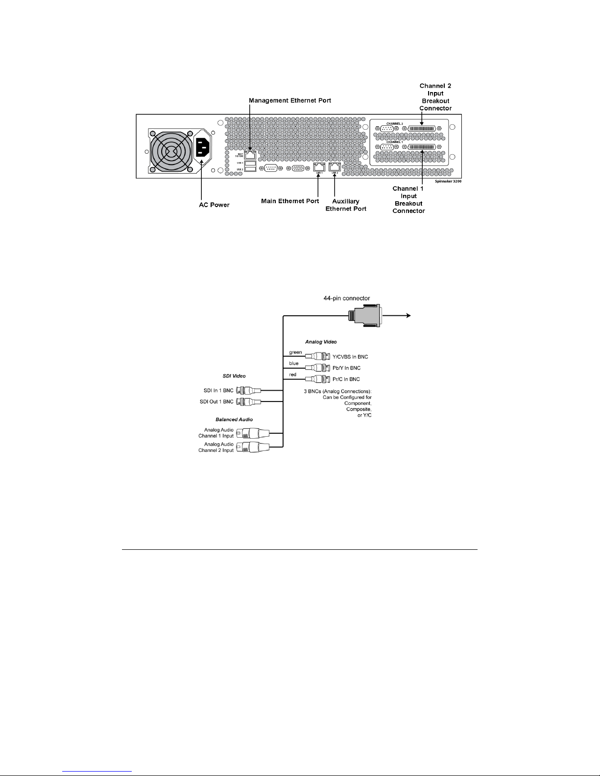
Analog Video and Audio
For analog sources, connect the provided breakout adapter cable for the analog video
and audio input signals to the Analog In 60-pin connector. For reference, consult the
following diagram of the breakout cable connections:
Figure 1: Cisco S3000/S5000 Series Media Processor Analog Input Breakout Adapter Cable
Use the following table to determine the proper connectors to use for analog
Component, Composite, and S-Video sources.
Color Label Component Composite S-Video
green Y/CVBS Y CVBS
blue Pb/Y Pb Y
red Pr/C Pr C
Cisco Media Processor utilizes locking BNC connectors for S-Video. If your source SVideo is not BNC based, you will need to use a BNC S-Video adapter such as an SVideo Male to Dual BNC Female Adapter 75 Ohm Coaxial.
4
Page 13
CISCO S3000/S5000 SERIES MEDIA PROCESSORS
Use the following diagram for reference while installing connections to a S3200 Series
unit:
Video and Audio
Connect each provided breakout adapter cable for the video and audio input signals to
the 44-pin breakout connector for each channel that will be used for encoding. For
reference, consult the following diagram of the breakout cable connections (outputs are
not used):
Figure 2: Cisco S3200 Series Media Processor Analog Input Breakout Adapter Cable
See the chart on page 4 to determine which connectors to use for analog sources.
Ethernet Ports
Connect the cable for the network that will be used to manage your Cisco Media
Processor to one of the available Ethernet ports. Use a Cat. 5 (or better) Ethernet cable.
5
Page 14

CISCO SYSTEMS, INC.
For ASF output, any of the Ethernet ports can be used to send data. For MPEG-2 TS
output, only the Main data port is used.
For Web management, any of the Ethernet ports
can be used.
Do not use the IPMI port for network connections.
NOTE:
Power Cable
Connect the properly grounded power cable to the AC power connector.
Powering Up
Except for the Cisco S3200 Series media Processor unit, place the On/Off switch on the
back of your Media Processor in the On position. Next, press and release the Power
switch on the front of the Media Processor.
Setting IP Addresses
The Ethernet ports for the Cisco Media Processor are configured to obtain IP addresses
using DHCP. Once the unit has been powered on, the front panel can be used to see
the IP address that was obtained using DHCP. If not using DHCP, you may use the
front panel to set IP addresses manually.
For more information on how to use the Front Panel, see Chapter 4:
Front Panel Controls on page 40.
NOTE:
To view or set the Media Procesor IP address, complete these steps:
1. For S3200 Series units only, press right at either the Channel 1 or Channel
2 menu item to get to the Main Menu.
2. Press the up or down keys to get to the IP Address Menu.
3. Press right to get to the LAN1 or LAN2 IP Menu.
4. Press right again to see the IP address. If this address is acceptable, then
you can now use a Web browser to connect to the machine. Go to Chapter
3: Web Interface for information on how to operate the Media Procesor
remotely via the Web Interface.
6
Page 15

CISCO S3000/S5000 SERIES MEDIA PROCESSORS
5. To change the address, press the Enter ( ) button.
6. The IP address is now editable. Use the up and down buttons to change
the number. Use the right and the left buttons to scroll across the numbers
to the digit that needs changing. The IP address is always a fixed 12-digit
value, with leading zeroes to pad each octet and decimal points in fixed
positions. For example, 192.168.1.10 is represented as 192.168.001.010.
7. Once a valid IP address is entered, press the Enter ( ) button.
8. Press the down button to navigate to the Netmask and Gateway settings.
Repeat steps 4, 5, and 6 for the Netmask and Gateway settings.
9. Once the IP address, Netmask, and Gateway are set correctly, press the
down button to the DHCP menu item and confirm that it is off. DHCP should
automatically be turned off when you edit the IP address. If it is not off, then
press the Enter ( ) button to edit the setting, then up to set it to Off, then
press the Enter ( ) button again to save the setting.
10. Once DHCP is set to Off, press the left button to go back to the LAN1 or
LAN2 IP menu.
11. When asked whether to apply changes, choose yes to commit the changes.
12. To verify the IP address has been set correctly, press Cancel (X) to return to
the top level menu, and proceed through steps 1 through 4 to see the
updated IP address. You can continue and set the other IP addresses
through the front panel, but typically once the Media Procesor IP address is
set, it is easier to set the remaining ports through the Web interface.
7
Page 16

CISCO SYSTEMS, INC.
3
WWeebb IInntteerrffaaccee
Remote Management via the Web
The Cisco Media Processor Web interface will allow you to manage the encoder by
browsing to its IP address. With this interface, you can:
Load and save encoding profiles
Configure the encoding parameters
Start and stop the encoder
Monitor status and general encoding statistics
Display system information
Manage the system
Opening the Interface
To open the Web interface of the encoder simply browse to:
https://<machine name or IP>/encadmin
For example:
https:://192.168.1.33/encadmin
3
3
If logged into Cisco Media Processor locally or remotely through Remote Desktop you
can bring up the Web interface via:
https://localhost/encadmin
8
Page 17
CISCO S3000/S5000 SERIES MEDIA PROCESSORS
NOTE:
The security certificate shipped with a Cisco Media
Processor unit is a temporary certificate for test purposes
only. A valid security certificate needs to be purchased and
installed.
Until the new certificate is installed, each time you bring up
the Web interface you will receive a warning message that
will require you to accept the shipped security certificate to
proceed.
For further information on security certificates, see Appendix
C: Troubleshooting on page 51.
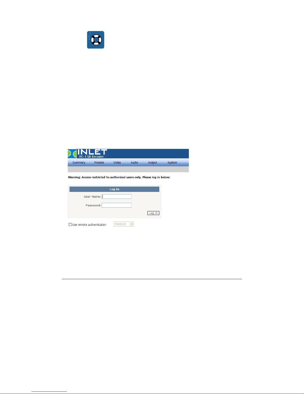
Logging In
Once you have browsed to the Cisco Media Processor Web interface, you must log in
with a valid user name and password on the following page:
Cisco Media Processor defines two user groups: encoder users and encoder
administrators. Encoder users are only allowed to view the status of the system.
Encoder administrators are allowed to configure, start and stop the system.
9
Page 18

CISCO SYSTEMS, INC.
A new unit will always have a factory-provided initial user name and password for each
group. The Use remote authentication checkbox must be unchecked to use these user
names. The initial encoder administrator name is:
User Name: admin
Password:
The initial encoder user name is:
User Name: user
Password:
The login page will indicate if a login attempt is made with an expired password. Under
the System tab, the User Account page allows passwords to be changed. Refer to the
User Account Page description on page 37 for further information. On this same tab, the
System Information page allows deletion and disabling of user accounts. Refer to the
System Page description on page 32 for further details.
See Appendix B: Managing User Accounts on page 50 for information on how to create
new users.
To log out, click the Logout link on the User Account page, then close the Web browser.
If no activity is detected for 15 minutes, you will be logged out automatically.
After logging out, it is still possible to view cached web pages by manually entering
them into the browser's address box. These pages, however, are simply cached from
the last time that page was visited; they do not reflect the current state nor can they be
used to modify the encoder state. The user must re-login in order to read or edit current
values.
encAdm1n
encUs3rs
10
Page 19

CISCO S3000/S5000 SERIES MEDIA PROCESSORS
Remote Authentication
You may also check the box to enable Remote Authentication. This feature allows a
company to centrally manage user accounts with an authentication server.
For RADIUS, enter the address (server name or IP address) of the remote server to be
used for authentication. Next, select the authentication method according to the server’s
configuration. Finally, enter the secret key shared between the user and the remote
server. RADIUS will use port 1812 for authentication.
11
Page 20

CISCO SYSTEMS, INC.
Summary Page
The main summary page shows status for Audio/Video, Output, Pre-Processing, and
the IP network settings.
Each Cisco Media Processor Web interface page indicates in the top right whether the
encoder is running or stopped.
Cisco S3200 Series Media Processor units offer two encoding channels, Channel 1 and
Channel 2. Choose the appropriate channel on any Web page to view or modify
information related to that channel. System information and advanced compression
options will apply to both channels.
12
Page 21
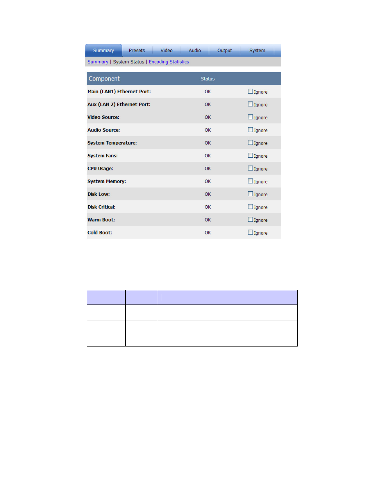
System Status Page
CISCO S3000/S5000 SERIES MEDIA PROCESSORS
The system status page displays the current status of alarms that are constantly being
monitored. These alarms are global alarms for the Media Procesor unit. Therefore, on
units with two channels, alarms will be triggered if the conditions are met on either
channel for audio and video alarms. The following chart details the alarm triggers and
recommended actions:
Alarm Indicator Recommended Action
Ethernet
Port
ALARM Check to make sure the cable is properly connected.
Make sure that video is active on the source currently
Video
Source
ALARM
selected on the Video page and that the cable for
that source is properly connected. Also, make sure
your video source equipment is powered on and
13
Page 22

CISCO SYSTEMS, INC.
working properly. On units with two channels, make
sure both channels have active video.
Audio has been silent on the selected audio source
for at least 15 seconds during encoding. Make sure
that audio is active on the source currently selected
on the Video page and that the cable for that source
Audio
Source
System
Temperature
System
Fans
ALARM
HIGH Contact Service personnel.
FAILURE Contact Service personnel.
CPU Usage HIGH Change options to make the encoding simpler.
is properly connected. On units with two channels,
make sure both channels have active audio. For
stereo analog audio, make sure audio is active on
both left and right. This alarm will return to OK after 1
second of audio is detected on the source during
encoding.
System
Memory
LOW Change options to make the encoding simpler.
Check if encodes are being saved to the local disk.
Disk Low LOW
Remove previously saved encoded files off the Media
Procesor unit. This alarm is triggered if available disk
space is < 2GB.
Check if encodes are being saved to the local disk.
Disk Critical LOW
Remove previously saved encoded files off the Media
Procesor unit. This alarm is triggered if available disk
space is < 1GB.
A system reboot is in progress. This alarm will
Warm Boot
or Cold Boot
ACTIVE
display OK after 5 minutes have elapsed from LCD
Panel service start, or 10 seconds after encoding
service start, whichever is sooner.
If these steps do not resolve the alarm, contact service personnel.
For any alarm, checking the Ignore box will turn off the notification of that alarm on this
page, as well as the on the front panel display and in the log.
The audio alarm only sets or clears during encoding. During
encoding, if stereo analog audio is missing on either left or right, the
alarm will be triggered. On 2-channel units, missing audio or video
NOTE:
on either channel will trigger the alarm.
14
Page 23

CISCO S3000/S5000 SERIES MEDIA PROCESSORS
Click the Encoding Statistics link to view live updated statistics from the encoder.
Encoding Statistics Page
The encoding statistics page provides several statistics while encoding is running. For
the encoding session, total encode time is reported. For the current frame, you can see
the frame’s number, quantization, type, and size. The quantization is a real time
measurement of quality. This number ranges from 1 to 31 with a lower number
corresponding to higher quality. If the quantization value is consistently high, this is an
indication that your allocated bit rate is too low for the specified resolution and the
current content being encoded.
Click Auto Refresh to refresh the encoding statistics once per second for approximately
60 seconds.
Presets Page
This page can restore factory default settings, save current settings in one of three
custom profiles, or load previously saved custom profiles. You may type a unique name
for each custom profile. A Media Procesor unit will ship with preloaded custom profiles
that may be useful, or you may save your own custom profiles.
15
Page 24

CISCO SYSTEMS, INC.
The currently loaded profile name will be designated on this page and also will be
displayed in the upper right corner of each Web page. For example, on the encoding
statistics page displayed on page 15, the profile name in use is 320x240 MP.
Video Page
The main video page allows for viewing or modification of the following video settings:
Source
Choose from the following video sources: SDI, Component, S-Video, and
Composite.
Format
You may choose between the NTSC formats of 720x480 or 720x486, or the PAL
format of 720x576.
Field Order
By default the captured video is assumed to be bottom field first. You may change
this by checking the Top Field First box.
Output Resolution
Choose from the available resolutions or choose Custom, which will make the
Cropping and Resizing settings available for modification. The pixel aspect ratio is
auto set for each of these presets.
16
Page 25

CISCO S3000/S5000 SERIES MEDIA PROCESSORS
Cropping
The cropping parameters apply a crop to the input image. Note that if an odd
number of lines are cropped from the top, the sense of which field is first (top or
bottom) will change and you will need to set the Field Order option accordingly.
Resizing
Specify the output resolution to be applied to the cropped image. If the resolution is
different than the original, scaling will be performed.
When changing a setting on any page, you must click Apply before
proceeding to a different page. Otherwise, the settings will not be
saved. Click Reload to return to the previously applied settings for
NOTE:
that page.
Video Encoding Parameters Page
From the main video page, click Encoding Parameters
to view or modify the following
settings:
Profile
Profiles for encoding include VC-1 Advanced Profile, VC-1 Main Profile, and VC-1
Simple Profile. Choose from the profiles available in the drop-down box for the
specific Media Procesor unit being used for encoding. See Appendix D:
Specifications on page 55 for information on which units support each profile.
17
Page 26

CISCO SYSTEMS, INC.
Mode
Choose CBR (Constant Bit Rate) or VBR (Variable Bit Rate) encoding. If the mode
is VBR, a parameter to specify Maximum Bit Rate in kb/sec will appear and the
Buffer Size parameter will be grayed.
Bit Rate
This setting indicates bits/sec in units of kb/sec. For example, a value of 1500 is
1.5Mbits/sec.
Key Frame Distance
This value (in milliseconds) sets the maximum distance between key frames. The
encoder may output key frames sooner than this interval (if it detects a scene
change, for example).
Buffer Size
The buffer size value (in milliseconds) sets the encoder buffer size. Two seconds
(2000 milliseconds) is a typical buffer size.
Interlace Encoding
Check this box if you want to perform interlaced based encoding. If not checked,
the encoder will process video as progressive. Interlace encoding is only available
for VC-1 Advanced Profile. VC-1 Main and Simple profiles do not support interlace
encoding. If you are not encoding as interlaced, then you should either choose to
de-interlace your video (for video content) or perform an inverse telecine (IVT) on
your video (for film based content). The Pre-Processing page is where these two
options are set.
ASF Streaming Mode
Choose between Broadcast and Web for the ASF streaming mode. If Web is
chosen, specify a value for Quality. The quality setting, from 0 to 100, is a tradeoff
between smoother video (Quality 0) and better quality video (Quality 100). A good
typical quality value is 80.
When Broadcast streaming is selected with Main Profile, the encoder emphasizes
smoother video over quality video, equivalent to Web streaming mode with Quality
0. In this mode, the encoder may drop (not encode) frames as needed. When
Broadcast streaming is selected with Advanced Profile, the encoder can encode
skip frames for frames the Main Profile encoder would drop. This allows for the
preservation of critical metadata, such as captioning and timecode.
18
Page 27

CISCO S3000/S5000 SERIES MEDIA PROCESSORS
PIP Video Page
From the main Video page, click PIP Video if you wish to encode a PIP stream. This
option is available in the S5000 Series. When you check Enable PIP on the PIP Video
page, the encoder will generate a separate video only PIP stream which is scaled from
the output image size. PIP encodes are always progressive.
You must choose Advanced Profile for encoding if you will be
enabling PIP video. See the Video Encoding Parameters Page on
page 17 for more information on encoding profiles.
NOTE:
Bit Rate
Set the PIP bit rate in units of kb/sec. For example, a value of 100 is .1 Mbits/sec..
The encoder produces CBR PIP streams. The PIP stream will not have captioning
information in it unless Open Captions are utilized.
Output Resolution
The default PIP output resolution is 96x96.
Pre-Processing Page
From the main Video page, click Pre-Processing
19
to modify the following:
Page 28

CISCO SYSTEMS, INC.
Interlacing Options
If your video input is interlaced and your resolution height is greater than the field
height, choose de-interlace if you wish to convert interlaced video to progressive.
For resolutions less than or equal to the field height (320x240 for example), no deinterlacing is required and none should be selected.
Both Main and Simple profiles only support progressive encoding and therefore,
unless the resolution is less than or equal to the field height, de-interlacing should
be chosen if not performing inverse telecine.
Choose inverse telecine (IVT) to convert film-based interlaced 30fps video to
progressive 24fps. If IVT is selected and the encoding mode is interlaced, the
encoder will produce IVT flags (top field first, bottom field first, repeat first field) in
the bitstream so that decoders know how to display the 24fps progressive video on
an interlaced display.
Deinterlace Mode
If deinterlacing is chosen, Cisco Media Processor provides multiple methods for
deinterlacing. The default, a motion adaptive deinterlace, attempts to preserve
spatial information in areas of motion while removing interlace artifacts in areas of
motion. The blend mode will blend two fields, maintaining temporal information
through motion blur. The interpolate mode removes temporal information and
interpolates even fields from odd fields, while interpolate denoise applies a noise
reduction filter after the deinterlace. The line double option simply creates even
field lines as direct copies of the odd field lines.
Miscellaneous Filters
Cisco Media Processor provides for various noise reducing filters. The normal filter
provides for moderate noise reduction. The smooth filter provides for large noise
reduction at the expense of softer images. For the dynamic filter, feedback from the
encoder during encoding will cause the active filter to change from none to normal
to smooth.
Advanced Compression Page
20
Page 29

CISCO S3000/S5000 SERIES MEDIA PROCESSORS
The advanced compression page gives you control over many of the VC-1 encoding
tools. This is important since, depending on your decoding solution (whether it be a
mobile device, an STB or a PC), you may need to limit or want to expand on the tools
used for encoding. All options have a <default> setting where the actual setting used
internally depends on multiple encoding setup factors, such as encode profile,
resolution and bit rate.
For S3200 Series units, advanced compression options will apply to
both channels.
NOTE:
Dquant Option
Dquant is the difference in the quantizer between the previous macroblock and the
current macroblock. Using this optimization can produce better quality in smooth
areas of the video picture, but increases the computation required to encode each
frame. If this optimization is activated, the strength of optimization is controlled by
the Dquant Strength value.
Setting Value Function
<default> Default based on encoder settings
Not used Dquant perceptual optimization disabled
I frames only Only I frames will be optimized
I and P frames Only I and P frames will be optimized
I, P, and B frames I, P, and B frames will be optimized
Dquant Strength
The Dquant Strength setting specifies the strength of the Dquant perceptual
optimization that will be used. The stronger the optimization, the more CPUintensive the encoding will be. This value is used only if the Dquant Option is
enabled.
Setting Value Function
<default> Default based on encoder settings
Codec-determined Strength of optimization will be determined by the
codec
21
Page 30

CISCO SYSTEMS, INC.
Weak optimization Strength of optimization is weak
Medium optimization Strength of optimization is medium
Strong optimization Strength of optimization is strong
Force B Frame Delta QP
This setting specifies the delta increase between the picture quantizer of the
anchor frame and the picture quantizer of the B frame. This setting can be from 0 to
31 and only takes effect when utilizing B frames.
In-Loop Deblocking
This setting specifies whether the codec should use the in-loop deblocking filter
during encoding. When the codec uses the in-loop deblocking filter, the edges of
the macroblocks in the output video frames will not be as noticeable. However, the
filter makes the image softer in appearance.
Force Median
This setting specifies whether the codec should use a median filtering during
encoding. Median filtering can reduce the encoded size of the video stream, but
can introduce compression artifacts. The artifacts associated with this filter can
include motion trails behind moving objects in the image.
Force Overlap
This setting specifies whether the codec will use overlap smoothing when
encoding. Overlap smoothing effects I frames only. When in use, the edges of the
macroblocks in the output video frames will not be as noticeable. However, the filter
makes the image softer in appearance.
Macroblock Mode Cost Method
This setting specifies the cost method used by the codec to determine which
macroblock mode to use. SAD/Hadamard uses only distortion to compute cost,
while RD accounts for both rate and distortion in the computation.
Motion Match Method
This setting specifies the method to use for motion matching. Available settings are
SAD, Hadamard, and Macroblock-adaptive, which configures the codec to make
decisions about which method to use on each macroblock. This can potentially
reduce overall computation required for encoding by performing the
computationally-intensive Hadamard transform only when appropriate.
22
Page 31

CISCO S3000/S5000 SERIES MEDIA PROCESSORS
Motion Search Level
This setting specifies the types of video information that are used in motion search
operations. Depending on the resolution, more complex methods below may
reduce search distance.
Setting Value
<default>
Luma Only
Luma with nearest-integer chroma
Luma with true chroma
Macroblock-adaptive with true chroma
Macroblock-adaptive with nearest-integer chroma
Motion Vector Coding Method
This setting specifies the method used to code the motion vector information in field
pictures and only applies to VC-1 AP interlaced encoding. Choose Encoder
defaults, or choose to improve encoding efficiency for highly spread-out horizontal
delta motion vector distributions, vertical distributions, or both.
Motion Vector Cost Method
This setting specifies the method used to estimate the cost of motion vector coding.
The cost is a measure of the amount of processing needed to encode the content.
The codec uses the cost to determine which features will be used in encoding.
Setting Value Function
<default> Default based on encoder settings
Static The encoder will use a static motion vector cost. All
blocks and macroblocks use the same motion vector
cost estimate.
Dynamic The encoder will use a dynamic motion vector cost.
The motion vector cost is varied between blocks to
achieve optimal visual quality.
23
Page 32

CISCO SYSTEMS, INC.
Number of B Frames
This value is the number of B frames to use between other types of frames. It can
range from 0 to 7, with 0 indicating that B frames will not be used. Note that some
decoders or system networks do not perform well when using B frames and thus
this setting should be thoroughly tested. For most applications, 0 B frames should
be used.
Perceptual Option
This setting specifies whether the codec should use conservative perceptual
optimization when encoding. Conservative perceptual optimization is a process by
which the codec attempts to identify "important" and "unimportant" regions in the
video frame. After identifying the regions of the frame, the codec will give a higher
priority to the quality of important regions, at the expense of the quality of
unimportant regions. The results of this feature will vary considerably depending on
the types of video being encoded.
Lookahead
This setting specifies the number of frames after the current frame, up to 30, that
the encoder will evaluate before encoding the current frame. Lookahead may
improve encoding efficiency.
Closed Captioning Page
Open Captions
When Open Captions is enabled, Line21 CC1 captions are decoded and rendered
on top of the incoming video. Thus, unlike 608, 708 or SAMI captioning, the
rendering of closed captions is done on top of video in the encoder instead of in the
24
Page 33

CISCO S3000/S5000 SERIES MEDIA PROCESSORS
decoder. This processing is independent of 608, 708, and SAMI captioning and
none of these options need to be enabled for open captions.
608
Check the appropriate box or boxes if you wish to process field 1 (CC1/CC2)
and/or field 2 (CC3/CC4) captioning on the input source and to either have CEA608 data inserted into the video elementary stream user data area (VC-1 Advanced
Profile only) or to enable SAMI output.
708
For VC-1 Advanced Profile only, if you have checked the appropriate boxes under
608 to process field 1 (CC1/CC2) and field 2 (CC3/CC4) captioning on the input
source, you may choose to enable the corresponding box or boxes to have upconverted CEA-708 data inserted into the video elementary stream user data area.
25
Page 34

CISCO SYSTEMS, INC.
Audio Page
When the video source is SDI, the encoder may optionally encode up to three WMA
audio streams from an SDI source. These three streams are stereo and are composed
of SDI audio channels 1 and 2 (stream 1), 3 and 4 (stream 2), and 5 and 6 (stream 3).
Check the Enabled box to enable encoding of a stereo channel.
When the video source is any of the analog inputs, only a single stereo analog stream
may be encoded.
Output Format
Use this setting to specify whether to encode audio using WMA or to pass through
AC3 audio. AC3 audio is only available in S5000 Series units and above.
Bit Rate
Choose from the list of available audio bit rates. The “odd” value bit rates (such as
191) indicate the use of the low delay WMA codec. If the output format is AC3
26
Page 35

CISCO S3000/S5000 SERIES MEDIA PROCESSORS
pass-through, you must specify the bit rate of input AC3 audio from the list of
available rates.
Sample Rate
If the output format is AC3 pass-through, you must specify the sample rate of input
audio from the list of available rates.
Language
Choose the language to apply to each stream.
Offset
Use this setting to specify an offset (in milliseconds) between audio and video. The
offset can be a positive or negative value. Typically this value is 0 unless you know
that your source audio and video are not in sync. If not in sync, you may use this
setting to adjust timing such that they are re-synced prior to encoding.
Output Page
The encoder will optionally save encoded data to the encoder hard disk. Use this page
to save to a user-specified WMV file at C:\inetpub\wwwroot\encadmin\output. If an
output file is not required, then the file name should be left blank. Click the View Files…
link to browse the output files and to copy them over your network.
When PIP is enabled, the encoder also generates PIP files. The PIP filename will be
filename.wmv.pip.wmv.
Min. Packet Size
Use this setting to specify the minimum size of the packets in the ASF stream. The
actual packet size may be larger based on audio and video compression
requirements. For streaming applications, a value no more than approximately
th
your compressed video data byte rate is suggested. For example, 8000 is a
1/15
good setting for a 1Mb/sec stream.
27
Page 36

CISCO SYSTEMS, INC.
SAMI Output
If 608 Closed Captioning is enabled, check this box to generate a .smi output file in
the same directory as the WMV file above. In order to output SAMI at least one of
the 608 check boxes must be enabled on the Video tab’s Closed Captioning page.
ASF Network Push Page
Check the appropriate boxes to enable ASF Push and/or ASF PIP Push. The encoder
can push ASF content to a local network port on the encoder. This creates and starts
publishing points on a Windows Media Server.
Make sure you have enabled ASF Push for the main video if you
enable ASF PIP Push.
NOTE:
Server/Port (and PIP Server/Port)
Enter the name of the Windows Media server. This can be an alias, a fully qualified
domain name, or an IP address of the Windows Media Server. The port is the UDP
port that the stream should be sent on.
Publishing Point (and PIP Publishing Point)
Enter the name of the publishing point on the server through which the encoded
stream will be broadcast. It should be one word name with no spaces. A checkbox
is available on this page to automatically remove the publishing point once the
encoder is stopped.
28
Page 37

CISCO S3000/S5000 SERIES MEDIA PROCESSORS
ASF Network Pull Page
Check the appropriate boxes to enable ASF Pull and/or ASF PIP Pull. This enables
Windows Media Servers and Windows Media Players to retrieve (“pull”) content as it is
being encoded from the encoder UDP port.
Make sure you have enabled ASF Pull for the main video if you
enable ASF PIP Pull.
NOTE:
Network Port (and PIP Network Port)
Enter the UDP port that the Windows Media Server will pull the stream from.
Maximum Clients (and PIP Maximum Clients)
Enter the maximum number of servers that can connect to the UDP port/stream.
TS Settings Page
29
Page 38

CISCO SYSTEMS, INC.
The encoder can produce a MPEG-2 single program transport stream (SPTS) for S5000
Series units and above. This is an MPEG-2 TS containing VC-1 video and WMA or AC3 audio. The encoder can optionally save this stream to disk. Use this page to save to a
user-specified TS file at C:\inetpub\wwwroot\encadmin\output. Click the View Files…
link to browse the output files and to copy them over your network. If an output file is not
required, then the file name should be left blank. When PIP is enabled, the PIP filename
will be filename.ts.pip.ts. This page also provides the following transport stream
configuration settings:
Make sure to specify settings for the main video stream if you
specify settings for a PIP stream.
NOTE:
Program Number (and PIP Program Number)
Enter the program number for the transport stream.
Program ID (and PIP Program ID)
Enter the Program ID for the transport stream.
Video PID (and PIP Video PID)
Enter the Video PID for the transport stream.
Audio PID
Enter the PID for the first audio stream. Note that subsequent audio streams are
currently assigned PIDs 1 and 2 higher than the base audio PID. For example, if
the Audio PID is set to 301, then the fist audio stream will have PID 301, the
second will have 302 and the third will have 303.
PMT Interval
The PMT Interval is how often to send PMT (program map table) data, in
milliseconds.
SEQ Interval
The SEQ Interval is how often to send sequence headers, again in msec units. If
set to 0 or anything equal to or smaller than a frame time, a SEQ header is output
for each I frame.
Miscellaneous
If it is desired to have the encoder insert NULL transport stream packets to smooth
out its delivery, then check the Null Packets check box.
30
Page 39

CISCO S3000/S5000 SERIES MEDIA PROCESSORS
TS Multicast Page
The encoder can multicast out compressed data encapsulated in a MPEG-2 Transport
Stream for S5000 Series units and above. The Enable Multicasting check box enables
multicast output.
Multicast Address (and PIP Multicast Address)
Enter the Multicast IP address that the encoder should use to output the TS
stream. The default address is 224.0.0.
1.
Port (and PIP Port)
Enter the UDP port number for the multicast TS stream.
TTL
This setting is the time to live value for the multicast socket.
Number of Packets
This setting indicates how many packets to group together in each multicast send.
No more than 8 packets can be grouped together. Each MPEG-2 TS packet is 188
bytes.
31
Page 40

CISCO SYSTEMS, INC.
System Page
The system information page provides the following information:
System Name
The system name is the computer name assigned to the encoder.
Serial Number
This is the serial number of the encoder.
Software Version
This is the currently installed version of software.
32
Page 41

CISCO S3000/S5000 SERIES MEDIA PROCESSORS
The following functions may also be performed on the system information page:
Front Panel Display
Check this box to disable (lock out) the front panel controls.
Remote Desktop
Check this box to allow remote desktop access to the encoder.
Expired User Accounts
Click the Delete button to delete any user accounts that have expired.
Inactive User Accounts
Click the Disable button to disable accounts that have been inactive.
SNMP Agent
Check this box to start the SNMP v2 agent service. Unchecking this box will stop
the service. For more information about the encoder settings that can be viewed
and modified through SNMP, see the MIB documentation in Appendix A.
Encoding parameters may be changed using SNMP sets while Cisco
Media Processor is encoding. However, the values will not be applied
(used) until encoding has been stopped and restarted.
NOTE:
If you click the Add button in any of the following SNMP sections, you
may be asked by your browser to temporarily allow scripted windows.
Click the bar above the page to allow the window, then click Add
NOTE:
again to display the window and type the appropriate input.
SNMP Communities
The display area for SNMP communities lists all accepted communities. To add a
community, click the Add button and type the name in the scripted window:
To assign rights to the community, click the community name to display the
33
Page 42

CISCO SYSTEMS, INC.
dropdown box to the right to choose the rights for that community. To remove a
community, click the community name to highlight it, then click Remove.
SNMP Security
The Send authentication trap checkbox causes all SNMP authentication attempts
to result in an authentication trap being triggered.
You may choose to allow any host providing a valid community name to
communicate with the Cisco Media Processor SNMP agent , or you may choose to
restrict incoming SNMP packets to a predefined list of allowed hosts. The display
area for SNMP security lists all allowed hosts. To add a host, click the Add button
and type the host name or IP address in the scripted window:
To remove a host, click the host name to highlight it, then click Remove.
SNMP Traps
The SNMP Traps section specifies the destinations of community-based traps.
These destinations may either be IP addresses or host names.
To begin, add a community to the dropdown list by clicking the Add button next to it
and type the community name in the scripted window:
To add trap destinations for a particular community, first select that community from
the dropdown list, then click the Add button next to the “Trap Destinations” list box
and type the destination in the scripted window:
34
Page 43

CISCO S3000/S5000 SERIES MEDIA PROCESSORS
To remove a community or a destination, click its name to highlight it, then click
Remove.
SNMP traps correspond to the system alarms detailed in the System Status Page
description on page 13. Any change in alarm state will generate a trap that
includes a variable indicating if the alarm was enabled or cleared. In addition, traps
are generated by changing the encoding state between running and stopped. The
following chart details the trap names, numbers, and severities assigned to each.
Severity 4 (Informational) is used for all alarm cleared traps except Warm or Cold
Boot, which generates a single trap after the system is rebooted. A trap will also
include the time the trap was generated.
Trap Name Trap Number Severity
Ethernet Mgt Port 1 2 (Minor)
Ethernet Out Port 2 2 (Minor)
Ethernet Aux Port 3 2 (Minor)
Video Signal 4 1 (Major)
Audio Signal 5 1 (Major)
High Temperature 6 0 (Critical)
Fan Failure 8 0 (Critical)
High CPU Utilization 9 1 (Major)
System Memory Low 10 1 (Major)
Disk Space Low 11 1 (Major)
Disk Space Critical 12 0 (Critical)
Cold Boot 13 3 (Warning)
Warm Boot 14 3 (Warning)
Encoder 1 Running 15 4 (Informational)
Encoder 2 Running 16 4 (Informational)
A single channel Cisco Media Processor will generate an “Encoder Running” trap
15 when the encoding state changes.
35
Page 44

CISCO SYSTEMS, INC.
Software Update Page
The software update page shows the currently installed version of software and allows
rollback to the previous version. Also, you may browse to the location of a new
software version, then click Update to install it. Make sure the update file is located on
the computer that is using the web interface to update the Media Procesor. Otherwise,
the update will first copy the file to the local computer before sending it to the Media
Procesor, which may take an extended time with slower connections.
During the update, the page will display an Updating message. Once the page goes
blank, close the browser window and wait a few minutes before reopening the browser
to re-login. Finally, return to the software update page to verify a successful update.
License Update Page
To update the license for future releases and features, click Get Current License to
obtain the license information, then send the file to Inlet support. After Inlet updates and
returns the license file, browse to it from this page, then click Update License to
complete the license update.
License Update requires popup windows to be unblocked. If popup
windows are blocked in your Web browser, first change the browser
setting to stop blocking popup windows, then proceed with the
NOTE:
license update process.
36
Page 45

CISCO S3000/S5000 SERIES MEDIA PROCESSORS
User Account Page
This page displays the user name in use, as well as the last known web-based logon
time. If there have been any failed attempts made since the last successful logon, then
a message will be displayed indicating the number of failed attempts.
To change the login password, type the old password and the new password, then
confirm the new password and click Change Password. Click the Logout
A new password must differ from the old password by at least two
link to log out.
positions.
NOTE:
All passwords must conform to the following criteria:
A minimum of 8 characters in length
Contain at least one number or special character
The same character must not occur in three consecutive positions
Passwords must not be blank or a repeat of the user ID
The Change Password function is not available for users who have
logged in using remote authentication.
NOTE:
37
Page 46

CISCO SYSTEMS, INC.
Logging Page
Enter the IP address of the server where log messages should be sent. The log
messages are sent using syslog format over UDP port 514.
User modification to any encoder setting, as well as to any machine-wide configuration
setting, is always logged to the Windows system Event Log. If the Media Procesor is
also set up to forward event log messages to a syslog server, then these audit
messages will be sent to the syslog server as well.
These audit messages can be seen via the Windows Event Viewer applet at Control
Panel>Administrative Tools>Event Viewer. The event Source will be listed as
“EncodingService”, “InletE1”, or “InletCapture”. Opening each event will provide a
description of what has been changed. For changes made via the front panel, the user
will be listed as Front Panel User.
Network Adapter Configuration Page
Cisco Media Processor has two Ethernet ports: Main (LAN1) and Aux (LAN2). To use
the Ethernet port, an IP address, subnet mask and gateway must be configured for the
port. An optional DNS IP address may also be set manually for any port not using
DHCP. By default, the Media Procesor will use DHCP to obtain IP addresses, which
may also be set manually. The currently set IP addresses may be viewed on the main
Summary page.
38
Page 47

CISCO S3000/S5000 SERIES MEDIA PROCESSORS
Configuration of Ethernet ports is only allowed if the media is
connected.
NOTE:
Starting/Stopping Encodes
To start an encode, click the Start link in the top right corner of any Cisco Media
Processor Web interface page. Once the encode starts, the encode status will change
to Running and the Start
link will be replaced by a Stop link, which can be clicked to
stop the encode.
While an encode is running, the Web interface may be used to view settings, but the
Apply and Reload buttons will be grayed, except for those on the System Information
page and the Logging page. To make changes to other settings, stop the encode, then
apply changes and restart.
Session Timeouts
After a period of inactivity on the Web pages, your login session will time out and you
will be redirected to the login page. The default value is 15 minutes.
The web timeout is stored in the following registry setting:
HKEY_LOCAL_MACHINE\SOFTWARE\Inlet\Spinnaker\SessionTimeout.
39
Page 48

CISCO SYSTEMS, INC.
4
FFrroonntt PPaanneell CCoonnttrroollss
The front panel controls can be used to configure a subset of the encoding parameters
available in the Web interface.
Front Panel Menu Layout
The following section describes the menu structure. Items in parentheses are for
clarification and do not show up on the display.
Use the ^ and v buttons to move up and down through the menu. Use the > (right)
button to move to submenus. Use the < (left) button to move back to the previous
menu. In submenus, the last setting viewed in a list of choices to select is immediately
applied. At any time, use the X (Cancel) button to return to the main menu.
For 2-channel Media Procesor units, first choose “Channel 1” or “Channel 2”, then the >
(right) button to go to the main menu for that channel. Cancel (X) returns to the
Channel menu.
4
4
Main Menu Submenus
VC-1 SD Encoder
(title screen)
IP Address Main (LAN1) IP IP Address
Netmask
Gateway
DHCP
Update
Aux (LAN2) IP IP Address
40
Page 49

CISCO S3000/S5000 SERIES MEDIA PROCESSORS
Main Menu Submenus
Netmask
Gateway
DHCP
Update
Load Profile Profile 1 (Default Profile)
Profile 2
Profile 3
Save Profile Profile 1 (Default Profile)
Profile 2
Profile 3
Setup Input Settings Video In Size
Field First
Video Crop T
Video Crop B
Video Crop L
Video Crop R
Video Out Size W
Video Out Size H
PIP Enable
PIP Size W
PIP Size H
Process Captions
Audio Ch 1/2 (Enable)
Audio Ch 3/4 (Enable)
Audio Ch 5/6 (Enable)
Audio Channel 1/2 Lang
Audio Channel 3/4 Lang
Audio Channel 5/6 Lang
Video Source
Encode Settings
41
Video Bit Rate
Video Buffer ms
I Frame ms
Page 50

CISCO SYSTEMS, INC.
Main Menu Submenus
Encode As (Interlace/Progressive)
Bit Rate PIP
Aud 1/2 Bit Rate
Aud 3/4 Bit Rate
Aud 5/6 Bit Rate
Aud 1/2 Delay
Aud 3/4 Delay
Aud 5/6 Delay
IVT
Deinterlace
TS Output
Multicast Port
Main Program #
Main Program ID
Main Stream ID
Main Video PID
Main Audio PID
PIP Program #
PIP Program ID
PIP Stream ID
PIP Video PID
SEQ Interval
PMT Interval
Null Packets
Multicast Enable
Main MCast Addr
Main Port
PIP MCast Addr
PIP Port
TTL (Time-to-Live)
Grouped Packets
42
Page 51

CISCO S3000/S5000 SERIES MEDIA PROCESSORS
Main Menu Submenus
ASF Output Main Port
Main Max Clients
PIP Port
PIP Max Clients
Power Reboot Confirm Reboot
Shutdown Confirm Shutdown
Start (encoding)
Stop (encoding)
Status
Changing values via the Front Panel Controls
For the following menu items simply press the Enter key to take action.
Start encoding
Stop encoding
Load Profile 1 (Default Profile)
Load Profile 2
Load Profile 3
Save Profile 1 (Default Profile)
Save Profile 2
Save Profile 3
For some menu items, there is a list of valid values. For example, PIP Enable can be
set On or Off. Use the up and down keys to scroll through this list. The last setting
viewed is immediately applied.
For other menu items, pressing the Enter key will place the front panel into an Edit
mode to allow the user to set values explicitly. Once Enter is pressed, a cursor will
appear to enable editing of the item. Use the left and right keys to move the cursor.
Use the up and down keys to change the value at the cursor. When finished, press
Enter to apply the new setting. If the setting is determined to be invalid, the previous
value will be restored. For IP addresses, you will be asked whether to apply changes
43
Page 52

CISCO SYSTEMS, INC.
after editing, even if the new setting matches the previous one. If you do not wish to
change the setting, select no.
Encoding parameters may be edited using the front panel controls
while Cisco Media Processor is encoding. However, the values will
not be applied (used) until encoding has been stopped and
NOTE:
restarted.
To verify an updated IP address after it is applied, return to the main
menu by using the Cancel (X) button, then return to the IP address
menu item to view the current setting.
NOTE:
The audio output format setting is not available on the front panel
interface. If you wish to switch between WMA and AC3 audio
formats, you must use the Web interface.
NOTE:
Front Panel Control Status
The front panel status item indicates a Ready… or Running… state. If the Alarm LED
is lit, the front panel will display active alarms in rotation. For a description of alarms,
see System Status Page on page 13.
44
Page 53

CISCO S3000/S5000 SERIES MEDIA PROCESSORS
AAppppeennddiixx AA:: TTeecchhnniiccaall GGuuiiddee
A
Understanding VC-1
Cisco Media Processor supports the following video profiles:
VC-1 Simple Profile (WMV3)
VC-1 Main Profile (WMV3)
VC-1 Advanced Profile (WVC1)
Files encoded according to these profiles are identified by their Four Character Code
(FOURCC). The FOURCC identifier is located at the beginning of a digital media file
and tells the system what libraries to utilize for decoding the file. Note that these profiles
are also equivalent to Windows Media 9 Video Simple, Main and Advanced.
VC-1 codec specification
The VC-1 standard was approved by SMPTE and is referenced as SMPTE 421M.
Although VC-1 and WMV9 refer to the same codec technology as far as Microsoft is
concerned, VC-1 is actually a superset of WMV9, containing more coding tools for
interlaced video sequences than the original WMV9 codec which concentrated on
progressive encoding for computer displays. The main goal of VC-1/WMV9 Advanced
Profile development and standardization was to support the compression of interlaced
content without first converting it to progressive, making the codec more attractive to
broadcast and video industry professionals. Leading content companies, solutions
providers and consumer electronics manufacturers are adopting Windows Media Video
9 (VC-1) to drive the widespread delivery of high-definition experiences to consumers.
VC-1 has been accepted by both of the next-generation DVD committees, HD-DVD and
Blu-ray Disc.
A
VC-1 contains a number of profile and level combinations that support the encoding of
many types of video. The profile determines the codec features that are available, and
determines the required decoder complexity. VC-1 supports the following three profiles:
Simple, Main, and Advanced. The Simple and Main profiles have been complete for
several years, and are most commonly referred to as WMV9. The completion of the
Advanced profile and consequent standardization of all profiles in the VC-1(SMPTE
421M) spec represents the final step in a comprehensive specification that delivers high
definition content—either interlaced or progressive—across any medium and to any
capable device.
45
Page 54

CISCO SYSTEMS, INC.
MIB for SNMP
The following table lists valid MIB groups, objects and their acceptable values:
Group Name Object Name Valid Values
inletEncoderStatusGroup inletEncodingStatus 1=Start, 2=Stop
inletVideoInputConfigGroup
(Main Video Page)
inletVideoOutputConfigGrou
p (Main Video Page)
inletVideoCompConfigGroup
(Encoding Parameters
Page)
inletVideoInputSource
1=SDI, 2=Component,
3=S-Video, 4=Composite
1=NTSC720x480
inletVideoInputFormat
2=NTSC720x486
3=PAL720x576
inletVideoInputOrder
1=top field first,
2=bottom field first
inletVideoOutputWidth >0 and <= input width
inletVideoOutputHeight >0 and <= input height
inletVideoOutputCropTop >=0
inletVideoOutputCropBottom >=0
inletVideoOutputCropLeft >=0, multiple of 2
inletVideoOutputCropRight >=0, multiple of 2
0=VC-1 Simple,
inletVideoCompProfile
1=VC-1 Main,
4=VC-1 Advanced
inletVideoCompMode 0=CBR, 2=VBR
inletVideoCompBitRate [1, 9999] (in kbps)
inletVideoCompFrameDist [1, 9999] (in ms)
inletVideoCompBufferSize [500, 9999] (in ms)
inletVideoCompInterlacedEncEnable True/False
0=Broadcast Stream
inletVideoCompQuality
Mode, 1-100 (In Web
Stream Mode)
46
Page 55

CISCO S3000/S5000 SERIES MEDIA PROCESSORS
inletVideoPipEnable True/False (S5000+)
inletVideoPipConfigGroup
inletVideoPreProcConfigGro
up (Pre-Processing Page)
inletOutCaptionConfigGroup
(Closed Captioning Page)
inletVideoPipOutputWidth 96, 128
inletVideoPipOutputHeight 128
inletVideoPipOutputBitRate [1, 9999]
inletVideoPreProcDeinterlace True/False
inletVideoPreProcIVT True/False
0=default, 1=Blend,
2=Interpolate,
inletVideoPreProcDeinterlaceMode
3=Interpolate Denoise,
4=Line Double, 5=Motion
Adaptive
inletVideoPreProcMiscFilter
0=None, 3=Normal,
4=Smooth, 5=Dynamic
inletOpenCaptionEnable True/False
inletCC608Cc1Cc2Enable True/False
inletCC608Cc3Cc4Enable True/False
inletCC708Service1Enable True/False
inletCC708Service2Enable True/False
inletCC708Service3Enable True/False
inletEncoderAudioConfig
(Audio Page)
inletCC708Service4Enable True/False
inletAudioChannelIndex [1, 6]
inletAudioSrcEnable True/False
inletAudioSrcOutputFormat 1=WMA, 5=AC3 (S5000+)
WMA=63, 64, 95, 96, 127,
128, 160, 191, 192
inletAudioSrcBitRate
AC3=32, 40, 48, 56, 64,
80, 96, 112, 128, 160,
192, 224, 256, 320, 384,
448, 512, 576, 640
47
Page 56

CISCO SYSTEMS, INC.
WMA=48000
inletAudioSrcSampleRate
AC3=32000, 44100,
48000
inletAudioSrcLanguage ISO language id
inletAudioSrcDelay [-9999, 9999]
inletAsfPushConfigGroup
(ASF Network Push Page)
inletAsfPullConfigGroup
(ASF Network Pull Page)
inletAsfServerIPandPort
Server:Port, blank to
disable
Name of WM Server
inletAsfMainPubPoint
publishing point; blank to
disable push
inletAsfMainAutoRemoveEnable True/False
inletAsfPipServerIPandPort
Server:Port, blank to
disable
Name of WM Server
inletAsfPipPoint
publishing point; blank to
disable PIP push
inletAsfPipAutoRemoveEnable True/False
inletAsfMainPort UDP Port, -1 to disable
inletAsfMainMaxClients [1, 50]
inletAsfPipPort UDP Port, -1 to disable
inletAsfPipMaxClients [1, 50]
inletMainMulticastEnable True/False
inletMainMulticastIpAddress aaa.bbb.ccc.ddd
inletMainMulticastPort <=65535
inletMainMulticastConfigGro
up (TS Pages)
inletMainMulticastTtl [1, 9999]
inletMainMulticastNp [1, 8]
inletMainMulticastProgNum [1, 65535]
inletMainMulticastProgId [0, 8191]
inletMainMulticastStreamId [0, 65535]
48
Page 57

inletPipMulticastConfigGrou
p (TS Pages)
CISCO S3000/S5000 SERIES MEDIA PROCESSORS
inletMainMulticastVideoPid [0, 65535]
inletMainMulticastAudioPid [0, 65535]
inletMainMulticastNpEnable True/False
inletMainMulticastSeqInterval [1, 9999]
inletMainMulticastPmtInterval [1, 9999]
inletPipMulticastEnable True/False
inletPipMulticastIpAddress aaa.bbb.ccc.ddd
inletPipMulticastPort <=65535
inletPipMulticastProgNum [1, 65535]
inletPipMulticastProgId [0, 8191]
inletPipMulticastStreamId [0, 65535]
inletPipMulticastVideoPid [0, 65535]
inletMgmtNetworkConfigGro
up (Network Adapter
Configuration Page)
inletTsOutNetworkConfigGro
up (Network Adapter
Configuration Page)
inletAuxNetworkConfigGrou
p (Network Adapter
Configuration Page)
All objects that can be set can be retrieved with the get command. Additionally, the
following objects are supported for the get command:
inletEncoderFrametype, inletEncoderFrameNum, inletEncoderFrameSize, and
inletEncoderFrameOutput.
inletTsMgmtIpAddress aaa.bbb.ccc.ddd
inletTsMgmtNetMask aaa.bbb.ccc.ddd
inletTsMgmtGateway aaa.bbb.ccc.ddd
inletTsOutputIpAddress aaa.bbb.ccc.ddd
inletTsOutputNetMask aaa.bbb.ccc.ddd
inletTsOutputGateway aaa.bbb.ccc.ddd
inletTsAuxIpAddress aaa.bbb.ccc.ddd
inletTsAuxNetMask aaa.bbb.ccc.ddd
inletTsAuxGateway aaa.bbb.ccc.ddd
49
Page 58

CISCO SYSTEMS, INC.
AAppppeennddiixx BB:: MMaannaaggiinngg UUsseerr
AAccccoouunnttss
To add a new user account to Cisco Media Processor, perform the following steps:
1. Log in through Remote Desktop.
2. Open Computer Management.
3. In the console tree, click Users (choose System Tools, then Local Users
and Groups, then Users).
4. On the Action menu, click New User.
5. Type the appropriate information in the dialog box.
6. Select or clear the check boxes for:
User must change password at next logon
User cannot change password
Password never expires
Account is disabled
7. Click Create, then click Close.
8. Click Open Groups in the console tree and add the new user to either the
Encoder User group or the Encoder Administrator group.
B
B
50
Page 59

CISCO S3000/S5000 SERIES MEDIA PROCESSORS
AAppppeennddiixx CC:: TTrroouubblleesshhoooottiinngg
Video Check Tool
To verify the presence of an input signal to your Cisco Media Processor unit, the
following tool is provided:
All Programs>Inlet Technologies>Inlet Spinnaker>Diag>Video Diag
After executing this program, the following window will appear:
C
C
After clicking one of the buttons to specify an input to Board 1 (or Board 2 for Channel 2
of a S3200 Series unit), a window will appear that displays any video on that input.
Resolve Security Certificate Warning
Installing a Security Certificate
Perform the following steps to install a valid, purchased security certificate:
Individual steps may vary, depending upon where the security
certificate is purchased. Instructions from the chosen certificate
company should supersede these steps when in conflict.
NOTE:
51
Page 60

CISCO SYSTEMS, INC.
1. Open the Internet Services Manager (IIS):
Click Start, then click Control Panel.
Double Click "Administrative Tools".
Double Click "Internet Information Services (IIS) Manager".
2. Under Web Sites, right-click your Web site and select Properties.
3. Click the Directory Security tab.
4. Under Secure Communications, click Server Certificate. If this button is
grayed, no security certificate has yet been imported into the machine.
Follow these steps to import a certificate:
Click Start, then click Run, and enter “mmc.exe”.
Click File, then click Add/Remove Snap-in.
In the dialog, click Add, select “Certificates”, then click Add.
Select “Computer account” and click Next.
Select “Local Computer” and click Finish.
Click Close to close the “Add Standalone Snap-in” box.
Click OK to close the “Add/Remove Snap-in” box.
Expand the “Certificates (Local Computer)” tree.
Right click “Personal”, select “All Tasks”, and select “Import”.
Browse to find your certificate file.
Click Next, then click Finish.
Close the “Console1” window and save settings.
Return to the IIS management window and click Server Certificate in
the “Default Web Site Properties” box.
5. The Web Site Certificate Wizard will open. Click Next.
6. Choose “Process the Pending Request and Install the Certificate”, then click
Next.
Important: The pending request must match the response file. If you deleted the
pending request in error you must generate a new CSR and replace this
certificate.
7. Select the location of the certificate response file, and then click Next.
8. Read the summary screen to be sure that you are processing the correct
certificate and then click Next.
You see a confirmation screen.
52
Page 61

CISCO S3000/S5000 SERIES MEDIA PROCESSORS
9. After you read this information, click Next.
10. Restart the World Wide Web Publishing service:
Click Start.
Right click My Computer, then select “Manage”.
Double click “Services and Applications”.
Double click “Services”.
Right click World Wide Web Publishing, then select “Restart”.
Turning Off Https
Alternately, you may choose to turn of https to resolve the security certificate warning
message.
If you choose to turn off https, your password will not be
encrypted.
WARNING:
Perform the following steps to turn off https for a Cisco Media Processor unit’s Web
interface:
1. Rename the file C:\Inetpub\wwwroot\encadmin\bin\WebPageSecurity.dll to
*.bak (or any backup extension).
2. Rename the file C:\Inetpub\wwwroot\encadmin\Web.Config to *.bak (or any
backup extension).
3. Restart the World Wide Web Publishing service:
Click Start.
Right click My Computer, then select “Manage”.
Double click “Services and Applications”.
Double click “Services”.
Right click World Wide Web Publishing, then select “Restart”.
After turning off https, use http to browse to the Web interface of your unit.
53
Page 62

CISCO SYSTEMS, INC.
Recovery Page
If logged in to a Cisco Media Processor unit, you may browse to the following URL to
reach the Recovery page:
https://<machine name or IP>/encadmin/recovery.aspx
Encoder Control
Click the Restart Encoding Service 1 button to restart the Windows service
responsible for encoding. For S3200 series units, this option will restart the service
for both channels, but Restart Encoding Service 2 will only restart the service for
channel 2.
Machine Control
Click the Reboot Machine button, then confirm, to reboot the unit.
Auto-start Encoder
By default, the encoder will restart after a reboot or a restart of the encoding
service if the encoder was running. Uncheck this box if you do not wish the
encoder to auto-start in this situation.
54
Page 63

CISCO S3000/S5000 SERIES MEDIA PROCESSORS
AAppppeennddiixx DD:: SSppeecciiffiiccaattiioonnss
The following specifications are for the Cisco S3000 and S5000 Series Media
Procesors. Features may vary between models and some features may not be available
at time of printing.
D
D
Inputs
Video
NTSC, PAL
SDI (BNC) – SMPTE 259M
Analog Component, S-video and Composite
Audio
3 stereo pairs over SDI embedded (BNC)
1 stereo pair of analog Balanced audio
Dolby AC-3 (S5000 only)
Codecs
Windows Media 9 (WMV3) – Simple, Main Profiles
VC-1 (WVC1) – Simple, Main Profiles
VC-1 (WVC1) - Advanced Profile (S3005, S3205 and S5000 only)
Windows Media Audio
Windows Media Audio Professional (ASF)
AC3 pass-through (S5000 only)
Output
Local
Simple/Main Profile: ASF file (.wmv)
Advanced Profile: ASF file
Advanced Profile: MPEG-2 Transport (S5000 only)
IP
ASF pull from encoder and push to WMS
55
Page 64

CISCO SYSTEMS, INC.
MPEG-2 Transport Multicast (S5000 only)
2 x 10/100/1000 BaseT Ethernet
Control
Remote Web-based
LCD front panel
Programmable encoding templates
Additional Features
Easy-to-use front panel control
Intuitive Web-based control
Simple, preconfigured set-ups
Encoder management service program
2-channel configuration available (S3200 and S3205 only)
Processing
Pre-processing
Scaling
Cropping
Deinterlacing
Inverse Telecine
Adaptive Noise Reduction Filters
Open Captions
Encoding
Adaptive GOP
CBR/VBR
VBI closed captioning processing for SAMI and user data
CEA 608 to 708 translation
Interlaced (S5000 only) and Progressive modes
Custom control over encoding tools
Picture-in-Picture (S5000 only)
Dynamic complexity balancing
Physical and Power
Dimensions
1RU: 17.0” (w) x 18.21” (d) x 1.72” (h) (S3000, S3005, S5000)
2RU: 17.0” (w) x 18.21” (d) x 3.47” (h) (S3200, S3205)
56
Page 65

CISCO S3000/S5000 SERIES MEDIA PROCESSORS
Power
100-240 VAC Full Range, 350W (2RU), 160W (1RU)
Certifications
FCC Part 15 Subpart B: This equipment has been tested and found to comply with the
limits for a Class A digital device, pursuant to Part 15 of the FCC Rules.
CE marked: According to EMC directive 89/336/EEC and 93/68/EEC (European standards
EN 55 022, EN 55 024, En 61000-3-2 and EN 61000-3-3).
cTUVus Certified to UL 60950-1:2003 and CAN/CSA-C22.2 No. 60950-1-03
CE marked: According to LVD directive 73/23/EEC and 93/68/EEC (European standard
EN 60950-1).
Operating Conditions
Ambient Temperature
Operating temperature: 0 to 50°C
Non-operating (storage): -10 to 60°C
Relative humidity
Non-operating: <95% non-condensing
57
Page 66

CISCO SYSTEMS, INC.
Advanced Compression, 20
Alarms, 13
ASF Pull, 29
ASF Push, 28
Audio, 26
Bit Rate, 18, 19, 26
Buffer Size, 18
Closed Captioning, 24
Connections, 3
Cropping, 17
DHCP, 38
DNS, 38
Encoding Parameters, 17, 19
Encoding statistics, 15
Field Order, 16
Front Panel, 6, 40
Front Panel Display, 33
Interlace Encoding, 18
Interlacing, 20
Key Frame Distance, 18
Language, 27
License Update, 36
Logging In, 9
NTSC, 16
Null Packets, 30
Output Resolution, 16, 19
Packet Size, 27
IInnddeexx
PAL, 16
Password, 10, 37
PIP Video, 19
PMT Interval, 30, 42
Pre-Processing, 12, 19
Presets, 15
Recovery Page, 54
Remote Authentication, 11
Remote Management, 8
Resizing, 17
Safety Information, i
SAMI, 2, 28
SDI, 16
Security Certificate, 51, 53
SEQ Interval, 30, 42
Session Timeouts, 39
Setting IP Addresses, 6
SNMP Agent, 33
SNMP Traps, 34
Software Update, 36
Software Version, 32
System Status, 13, 35, 44
Troubleshooting, 51
TS Multicast, 31
TTL, 31
User Accounts, 10, 37, 50
VC-1, 17, 45
II
58
Page 67

CISCO S3000/S5000 SERIES MEDIA PROCESSORS
Cisco 1-Year Limited Hardware Warranty
Terms
The following are special terms applicable to your hardware warranty. Your formal
Warranty Statement, including the warranty applicable to Cisco software, appears in the
Cisco Information Packet that accompanies your Cisco product.
Duration of Hardware Warranty: One (1) Year
Replacement, Repair or Refund Procedure for Hardware: Cisco or its service center
will use commercially reasonable efforts to ship a replacement part within ten (10) working
days after receipt of the RMA request. Actual delivery times may vary depending on
Customer location.
Cisco reserves the right to refund the purchase price as its exclusive warranty remedy.
To Receive a Return Materials Authorization (RMA) Number: Please contact the party
from whom you purchased the product. If you purchased the product directly from Cisco,
contact your Cisco Sales and Service Representative.
Complete the form below and keep for ready reference.
Product purchased from:
Their telephone number:
Product Model and Serial number:
Maintenance Contract number:
Product warranty terms and other information applicable to Cisco products are available at
the following URL:
http://www.cisco.com/go/warranty
78-10747-01D0
59
 Loading...