

Page 1

Cisco APIC M3/L3 Server Installation and Service Guide
First Published: 2018-10-25
Americas Headquarters
Cisco Systems, Inc.
170 West Tasman Drive
San Jose, CA 95134-1706
USA
http://www.cisco.com
Tel: 408 526-4000
800 553-NETS (6387)
Fax: 408 527-0883
Page 2

THE SPECIFICATIONS AND INFORMATION REGARDING THE PRODUCTS IN THIS MANUAL ARE SUBJECT TO CHANGE WITHOUT NOTICE. ALL STATEMENTS,
INFORMATION, AND RECOMMENDATIONS IN THIS MANUAL ARE BELIEVED TO BE ACCURATE BUT ARE PRESENTED WITHOUT WARRANTY OF ANY KIND,
EXPRESS OR IMPLIED. USERS MUST TAKE FULL RESPONSIBILITY FOR THEIR APPLICATION OF ANY PRODUCTS.
THE SOFTWARE LICENSE AND LIMITED WARRANTY FOR THE ACCOMPANYING PRODUCT ARE SET FORTH IN THE INFORMATION PACKET THAT SHIPPED WITH
THE PRODUCT AND ARE INCORPORATED HEREIN BY THIS REFERENCE. IF YOU ARE UNABLE TO LOCATE THE SOFTWARE LICENSE OR LIMITED WARRANTY,
CONTACT YOUR CISCO REPRESENTATIVE FOR A COPY.
The following information is for FCC compliance of Class A devices: This equipment has been tested and found to comply with the limits for a Class A digital device, pursuant to part 15
of the FCC rules. These limits are designed to provide reasonable protection against harmful interference when the equipment is operated in a commercial environment. This equipment
generates, uses, and can radiate radio-frequency energy and, if not installed and used in accordance with the instruction manual, may cause harmful interference to radio communications.
Operation of this equipment in a residential area is likely to cause harmful interference, in which case users will be required to correct the interference at their own expense.
The following information is for FCC compliance of Class B devices: This equipment has been tested and found to comply with the limits for a Class B digital device, pursuant to part 15 of
the FCC rules. These limits are designed to provide reasonable protection against harmful interference in a residential installation. This equipment generates, uses and can radiate radio
frequency energy and, if not installed and used in accordance with the instructions, may cause harmful interference to radio communications. However, there is no guarantee that interference
will not occur in a particular installation. If the equipment causes interference to radio or television reception, which can be determined by turning the equipment off and on, users are
encouraged to try to correct the interference by using one or more of the following measures:
• Reorient or relocate the receiving antenna.
• Increase the separation between the equipment and receiver.
• Connect the equipment into an outlet on a circuit different from that to which the receiver is connected.
• Consult the dealer or an experienced radio/TV technician for help.
Modifications to this product not authorized by Cisco could void the FCC approval and negate your authority to operate the product
The Cisco implementation of TCP header compression is an adaptation of a program developed by the University of California, Berkeley (UCB) as part of UCB’s public domain version of
the UNIX operating system. All rights reserved. Copyright©1981, Regents of the University of California.
NOTWITHSTANDING ANY OTHER WARRANTY HEREIN, ALL DOCUMENT FILES AND SOFTWARE OF THESE SUPPLIERS ARE PROVIDED "AS IS" WITH ALL FAULTS.
CISCO AND THE ABOVE-NAMED SUPPLIERS DISCLAIM ALL WARRANTIES, EXPRESSED OR IMPLIED, INCLUDING, WITHOUT LIMITATION, THOSE OF
MERCHANTABILITY, FITNESS FOR A PARTICULAR PURPOSE AND NONINFRINGEMENT OR ARISING FROM A COURSE OF DEALING, USAGE, OR TRADE PRACTICE.
IN NO EVENT SHALL CISCO OR ITS SUPPLIERS BE LIABLE FOR ANY INDIRECT, SPECIAL, CONSEQUENTIAL, OR INCIDENTAL DAMAGES, INCLUDING, WITHOUT
LIMITATION, LOST PROFITS OR LOSS OR DAMAGE TO DATA ARISING OUT OF THE USE OR INABILITY TO USE THIS MANUAL, EVEN IF CISCO OR ITS SUPPLIERS
HAVE BEEN ADVISED OF THE POSSIBILITY OF SUCH DAMAGES.
Any Internet Protocol (IP) addresses and phone numbers used in this document are not intended to be actual addresses and phone numbers. Any examples, command display output, network
topology diagrams, and other figures included in the document are shown for illustrative purposes only. Any use of actual IP addresses or phone numbers in illustrative content is unintentional
and coincidental.
Cisco and the Cisco logo are trademarks or registered trademarks of Cisco and/or its affiliates in the U.S. and other countries. To view a list of Cisco trademarks, go to this URL: www.cisco.com
go trademarks. Third-party trademarks mentioned are the property of their respective owners. The use of the word partner does not imply a partnership relationship between Cisco and any
other company. (1721R)
©
2018 Cisco Systems, Inc. All rights reserved.
Page 3

CONTENTS
CHAPTER 1
CHAPTER 2
Overview 1
Overview 1
External Features 1
Serviceable Component Locations 3
Summary of Server Features 5
Installing the Server 7
Preparing for Installation 7
Installation Warnings and Guidelines 7
Grounding Requirements 9
Rack Requirements 9
Installing the Server in a Rack 10
Installing the Cable Management Arm (Optional) 12
Reversing the Cable Management Arm (Optional) 13
Initial Server Setup 14
Connecting to the Server Locally For Setup 15
CHAPTER 3
Connecting to the Server Remotely For Setup 16
Setting Up the System With the Cisco IMC Configuration Utility 17
NIC Mode and NIC Redundancy Settings 19
Updating the BIOS and Cisco IMC Firmware 20
Accessing the System BIOS 21
Smart Access Serial 21
Smart Access USB 22
Maintaining the Server 23
Status LEDs and Buttons 23
Cisco APIC M3/L3 Server Installation and Service Guide
iii
Page 4

Contents
Front-Panel LEDs 23
Rear-Panel LEDs 26
Internal Diagnostic LEDs 27
Preparing For Component Installation 28
Required Equipment For Service Procedures 29
Shutting Down and Removing Power From the Server 29
Shutting Down Using the Power Button 29
Shutting Down Using The Cisco IMC GUI 30
Shutting Down Using The Cisco IMC CLI 30
Removing the Server Top Cover 30
Serial Number Location 31
Hot Swap vs Hot Plug 31
Removing and Replacing Components 32
Serviceable Component Locations 32
Replacing SAS/SATA Hard Drives or Solid State Drives 34
SAS/SATA Drive Population Guidelines 34
4K Sector Format SAS/SATA Drives Considerations 34
Replacing a SAS/SATA Drive 35
Replacing a Front-Loading NVMe SSD 36
Front-Loading NVMe SSD Population Guidelines 36
Front-Loading NVME SSD Requirements and Restrictions 37
Enabling Hot-Plug Support in the System BIOS 37
Replacing a Front-Loading NVMe SSD 38
Installing a PCIe Cable For Front-Loading NVMe SSDs 39
Replacing HHHL Form-Factor NVMe Solid State Drives 40
HHHL SSD Population Guidelines 40
HHHL Form-Factor NVME SSD Requirements and Restrictions 40
Replacing an HHHL Form-Factor NVMe SSD 41
Replacing Fan Modules 42
Replacing Memory DIMMs 43
DIMM Population Rules and Memory Performance Guidelines 43
Replacing DIMMs 45
Replacing CPUs and Heatsinks 46
CPU Configuration Rules 46
Cisco APIC M3/L3 Server Installation and Service Guide
iv
Page 5

Tools Required For CPU Replacement 46
Replacing a CPU and Heatsink 47
Additional CPU-Related Parts to Order with RMA Replacement CPUs 53
Additional CPU-Related Parts to Order with RMA Replacement System Chassis 53
Moving an M5 Generation CPU 54
Replacing a Mini-Storage Module 58
Replacing a Mini-Storage Module Carrier 59
Replacing an SD Card in a Mini-Storage Carrier For SD 60
Replacing an M.2 SSD in a Mini-Storage Carrier For M.2 61
Replacing a Micro SD Card 61
Replacing an Internal USB Drive 63
Replacing a USB Drive 63
Enabling or Disabling the Internal USB Port 64
Contents
Replacing the RTC Battery 65
Replacing Power Supplies 66
Replacing AC Power Supplies 66
Replacing a PCIe Card 67
PCIe Slot Specifications 67
Replacing a PCIe Card 68
Cisco Virtual Interface Card (VIC) Considerations 70
Replacing an mLOM Card 71
Replacing an mRAID Riser (Riser 3) 72
Replacing a SAS Storage Controller Card (RAID or HBA) 74
Storage Controller Card Firmware Compatibility 74
Replacing a SAS Storage Controller Card (RAID or HBA) 75
Replacing the Supercap (RAID Backup) 76
Replacing a SATA Interposer Card 78
Replacing a Chassis Intrusion Switch 80
Installing a Trusted Platform Module (TPM) 81
TPM Considerations 81
Installing and Enabling a TPM 82
Service Headers and Jumpers 85
Using the Clear CMOS Header (J38, Pins 9 - 10) 86
Using the BIOS Recovery Header (J38, Pins 11 - 12) 86
Cisco APIC M3/L3 Server Installation and Service Guide
v
Page 6

Contents
Procedure 1: Reboot With recovery.cap File 87
Procedure 2: Use BIOS Recovery Header and bios.cap Recovery File 87
Using the Clear Password Header (J38, Pins 13 - 14) 88
Using the Boot Alternate Cisco IMC Image Header (J39, Pins 1 - 2) 89
Using the Reset Cisco IMC Password to Default Header (J39, Pins 3 - 4) 90
Using the Reset Cisco IMC to Defaults Header (J39, Pins 5 - 6) 90
APPENDIX A
APPENDIX B
Server Specifications 93
Server Specifications 93
Physical Specifications 93
Environmental Specifications 93
Power Specifications 94
770 W AC Power Supply 94
1050 W DC Power Supply 95
Power Cord Specifications 96
Storage Controller Considerations 99
Supported Storage Controllers and Cables 99
Storage Controller Card Firmware Compatibility 100
Write-Cache Policy for Cisco 12G SAS Modular RAID Controller 101
Mixing Drive Types in RAID Groups 101
RAID Controller Migration 102
Storage Controller and Backplane Connectors 102
Embedded SATA RAID Controller 104
Embbeded SATA RAID Requirements 104
Embedded SATA RAID Controller Considerations 105
Embedded SATA RAID: Two SATA Controllers 105
Enabling SATA Mode For the Embedded Controllers 106
Accessing the Software RAID Configuration Utility 107
Installing LSI MegaSR Drivers For Windows and Linux 107
Downloading the MegaSR Drivers 107
Microsoft Windows Server Drivers 108
Linux Drivers 109
For More RAID Utility Information 113
Cisco APIC M3/L3 Server Installation and Service Guide
vi
Page 7

Contents
APPENDIX C
APPENDIX D
GPU Card Installation 115
Server Firmware Requirements 115
GPU Card Configuration Rules 115
Requirement For All GPUs: Memory-Mapped I/O Greater Than 4 GB 115
Replacing a Single-Wide GPU Card 116
Installing Drivers to Support the GPU Cards 118
1. Updating the Server BIOS 118
2. Updating the GPU Card Drivers 119
Installation For Cisco UCS Manager Integration 121
Installation For Cisco UCS Manager Integration 121
Cisco APIC M3/L3 Server Installation and Service Guide
vii
Page 8

Contents
viii
Cisco APIC M3/L3 Server Installation and Service Guide
Page 9

Overview
• Overview, on page 1
• External Features, on page 1
• Serviceable Component Locations, on page 3
• Summary of Server Features, on page 5
Overview
Cisco APIC Server M3 and L3 (APIC-SERVER-M3 and APIC-SERVER-L3)—Small form-factor (SFF)
drives, with 10-drive backplane. Supports up to 10 2.5-inch SAS/SATA drives. Drive bays 1 and 2 support
NVMe SSDs.
External Features
This topic shows the external features of the server versions.
CHAPTER 1
Cisco APIC M3 and L3 Server (SFF Drives) Front Panel Features
The following figure shows the front panel features of the small form-factor drive versions of the server.
Cisco APIC M3/L3 Server Installation and Service Guide
1
Page 10

External Features
Figure 1: Cisco APIC M3 and L3 Server (SFF Drives) Front Panel
Overview
1
Fan status LED7Drive bays 1 – 10 support SAS/SATA hard disk
drives (HDDs) and solid state drives (SSDs)
2
Network link activity LED8• APIC-Server-M3 and L3: Drive bays 1 and
2 support NVMe PCIe SSDs.
Temperature status LED9Power button/power status LED3
Pull-out asset tag10Unit identification button/LED4
11System status LED5
KVM connector
(used with KVM cable that provides one DB-15
VGA, one DB-9 serial, and two USB connectors)
-Power supply status LED6
Cisco APIC M3 and L3 Server Rear Panel Features
The rear panel features are the same for all versions of the server.
Cisco APIC M3/L3 Server Installation and Service Guide
2
Page 11
Overview
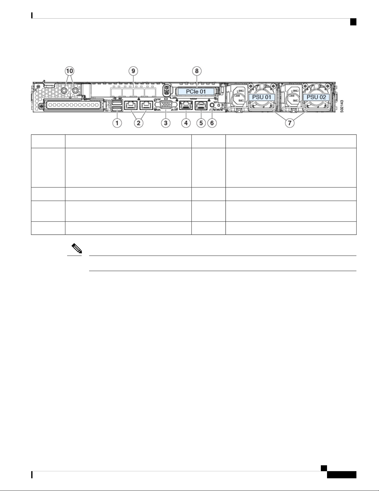
Figure 2: Cisco APIC M3 and L3 Server Rear Panel
Serviceable Component Locations
Rear unit identification button/LED6USB 3.0 ports (two)1
2
LAN2)
The dual LAN ports can support 1 Gbps and 10
Gbps, depending on the link partner capability.
91-Gb Ethernet dedicated management port4
Note
The VIC 1455 has 4 ports, port-0, port-1, port-3, and port-4 from left to right.
• All ports must have the same speed, either 10-Gigabit or 25-Gigabit.
• Port-0 and port-1 is one pair, corresponding to eth2-1 on APIC and port-2 and port-3 is another pair,
corresponding to eth2-2 on APIC. Only one connection is allowed for each pair. For example, you can
connect one cable to either port-0 or port-1, and connect another cable to either port-2 or port-3 (please
do not connect two cables on any pair).
Power supplies (two, redundant as 1+1)7Dual 1-Gb/10-Gb Ethernet ports (LAN1 and
PCIe riser 1/slot 1 (x16 lane)8VGA video port (DB-15 connector)3
VIC 1455 with external 10/25-Gigabit Ethernet ports
(4)
Threaded holes for dual-hole grounding lug10Serial port (RJ-45 connector)5
Serviceable Component Locations
This topic shows the locations of the field-replaceable components and service-related items. The view in the
following figure shows the server with the top cover removed.
Cisco APIC M3/L3 Server Installation and Service Guide
3
Page 12

Serviceable Component Locations
Figure 3: Cisco APIC M3 and L3 Server, Serviceable Component Locations
Overview
1
RTC battery, vertical socket9Front-loading drive bays 1–10 support SAS/SATA
drives.
10Cooling fan modules (seven, hot-swappable)2
Power supplies (hot-swappable when redundant as
1+1)
11Supercap unit mounting bracket (RAID backup)3
Trusted platform module (TPM) socket on
motherboard (not visible in this view)
12DIMM sockets on motherboard (12 per CPU)4
PCIe riser 1/slot 1 (half-height, x16 lane)
Includes PCIe cable connectors for front-loading
NVMe SSDs (x8 lane)
13CPUs and heatsinks (up to two)5
VIC 1455 with external 10/25-Gigabit Ethernet ports
(4)
6
Available (empty) PCIe slot14Mini storage module socket
Supports either an SD card module with two SD
card slots; or an M.2 module with two NVMe or
SATA M.2 SSD slots.
15Chassis intrusion switch (optional)7
PCIe cable connectors for front-loading NVMe SSDs
on PCIe riser 2
Micro-SD card socket on PCIe riser 116Internal USB 3.0 port on motherboard8
Cisco APIC M3/L3 Server Installation and Service Guide
4
Page 13
Overview
Summary of Server Features
The following table lists a summary of server features.
Summary of Server Features
DescriptionFeature
One rack-unit (1RU) chassisChassis
Central Processor
Baseboard management
Network and management I/O
Up to two CPUs from the Intel Xeon Processor Scalable Family.
This includes CPUs from the following series:
• Intel Xeon Bronze 3XXX Processors
• Intel Xeon Silver 4XXX Processors
• Intel Xeon Gold 5XXX Processors
• Intel Xeon Gold 6XXX Processors
• Intel Xeon Platinum 8XXX Processors
24 DDR4 DIMM sockets on the motherboard (12 each CPU)Memory
Multi-bit error protection is supportedMulti-bit error protection
BMC, running Cisco Integrated Management Controller (Cisco
IMC) firmware.
Depending on your Cisco IMC settings, Cisco IMC can be
accessed through the 1-Gb dedicated management port, the
1-Gb/10-Gb Ethernet LAN ports, or a Cisco virtual interface card.
Rear panel:
• One 1-Gb Ethernet dedicated management port (RJ-45
connector)
• Two 1-Gb/10-Gb BASE-T Ethernet LAN ports (RJ-45
connectors)
The dual LAN ports can support 1 Gbps and 10 Gbps,
depending on the link partner capability.
• One RS-232 serial port (RJ-45 connector)
• One VGA video connector port (DB-15 connector)
• Two USB 3.0 ports
Front panel:
• One front-panel keyboard/video/mouse (KVM) connector
that is used with the KVM cable, which provides two USB
2.0, one VGA, and one DB-9 serial connector.
Cisco APIC M3/L3 Server Installation and Service Guide
5
Page 14

Summary of Server Features
Overview
DescriptionFeature
Modular LOM
WoL
Power
ACPI
InfiniBand
Storage, front-panel
Storage, internal
One dedicated socket (x16 PCIe lane) that can be used to add an
mLOM card for additional rear-panel connectivity.
The two 1-Gb/10-Gb BASE-T Ethernet LAN ports support the
wake-on-LAN (WoL) standard.
Two power supplies, redundant as 1+1:
• AC power supplies 770 W AC each
The advanced configuration and power interface (ACPI) 4.0
standard is supported.
Seven hot-swappable fan modules for front-to-rear cooling.Cooling
Two horizontal PCIe expansion slots on a PCIe riser assembly.PCIe I/O
The PCIe bus slots in this server support the InfiniBand
architecture.
Cisco APIC M3 and L3 (APIC-SERVER-M3 and
APIC-SERVER-L3)—Small form-factor (SFF) drives, with
10-drive backplane. Supports up to 10 2.5-inch SAS/SATA drives.
Drive bays 1 and 2 support NVMe SSDs.
The server has these internal storage options:
Storage management
RAID backup
• One USB port on the motherboard.
• Mini-storage module socket, optionally with either:
• SD card module. Supports up to two SD cards.
• M.2 SSD module. Supports either two SATA M.2 SSDs
or two NVMe M.2 SSDs.
• One micro-SD card socket on PCIe riser 1.
The server has a dedicated internal mRAID riser that supports
one of the following storage-controller options:
• A PCIe-style Cisco modular RAID controller card
(SAS/SATA).
• A PCIe-style interposer card for the server’s embedded
SATA RAID controller.
The server has a mounting bracket near the cooling fans for the
supercap unit that is used with the Cisco modular RAID controller
card.
Integrated VGA video.Integrated video
Cisco APIC M3/L3 Server Installation and Service Guide
6
Page 15

Installing the Server
• Preparing for Installation, on page 7
• Installing the Server in a Rack, on page 10
• Initial Server Setup, on page 14
• NIC Mode and NIC Redundancy Settings, on page 19
• Updating the BIOS and Cisco IMC Firmware, on page 20
• Accessing the System BIOS, on page 21
• Smart Access Serial, on page 21
• Smart Access USB, on page 22
Preparing for Installation
This section contains the following topics:
Installation Warnings and Guidelines
CHAPTER 2
Note
Warning
Before you install, operate, or service a server, review the Regulatory Compliance and Safety Information for
important safety information.
IMPORTANT SAFETY INSTRUCTIONS
This warning symbol means danger. You are in a situation that could cause bodily injury. Before you
work on any equipment, be aware of the hazards involved with electrical circuitry and be familiar with
standard practices for preventing accidents. Use the statement number provided at the end of each
warning to locate its translation in the translated safety warnings that accompanied this device.
Statement 1071
Cisco APIC M3/L3 Server Installation and Service Guide
7
Page 16

Installation Warnings and Guidelines
Installing the Server
Warning
Warning
Warning
Warning
To prevent the system from overheating, do not operate it in an area that exceeds the maximum
recommended ambient temperature of: 35° C (95° F).
Statement 1047
The plug-socket combination must be accessible at all times, because it serves as the main disconnecting
device.
Statement 1019
Installation of the equipment must comply with local and national electrical codes.
Statement 1074
This unit is intended for installation in restricted access areas. A restricted access area can be accessed
only through the use of a special tool, lock, and key, or other means of security.
Statement 1017
Warning
Caution
Caution
Caution
This product relies on the building's installation for short-circuit (over current) protection. Ensure that
the protective devices is rated not greater than 20A (North America), 16A (Europe),and 13A (UK).
Statement 1005
To ensure proper airflow it is necessary to rack the servers using rail kits. Physically placing the units on top
of one another or “stacking” without the use of the rail kits blocks the air vents on top of the servers, which
could result in overheating, higher fan speeds, and higher power consumption. We recommend that you mount
your servers on rail kits when you are installing them into the rack because these rails provide the minimal
spacing required between the servers. No additional spacing between the servers is required when you mount
the units using rail kits.
Avoid uninterruptible power supply (UPS) types that use ferroresonant technology. These UPS types can
become unstable with systems such as the Cisco UCS, which can have substantial current draw fluctuations
from fluctuating data traffic patterns.
To prevent loss of input power, ensure the total maximum loads on the circuits supplying power to the switch
are within the current ratings for the wiring and breakers.
Cisco APIC M3/L3 Server Installation and Service Guide
8
Page 17

Installing the Server
When you are installing a server, use the following guidelines:
• Plan your site configuration and prepare the site before installing the server.
• Ensure that there is adequate space around the server to allow for accessing the server and for adequate
airflow. The airflow in this server is from front to back.
• Ensure that the air-conditioning meets the thermal requirements listed in the Environmental Specifications,
on page 93.
• Ensure that the cabinet or rack meets the requirements listed in the Rack Requirements, on page 9.
• Ensure that the site power meets the power requirements listed in the Power Specifications, on page 94.
If available, you can use an uninterruptible power supply (UPS) to protect against power failures.
Grounding Requirements
The switch is sensitive to variations in voltage supplied by the power sources. Overvoltage, undervoltage,
and transients (or spikes) can erase data from memory or cause components to fail. To protect against these
types of problems, ensure that there is an earth-ground connection for the switch. You can connect the grounding
pad on the switch either directly to the earth-ground connection or to a fully bonded and grounded rack.
Grounding Requirements
When you properly install the chassis in a grounded rack, the switch is grounded because it has a metal-to-metal
connection to the rack. Alternatively, you can ground the chassis by using a customer-supplied grounding
cable that meets your local and national installation requirements (we recommend 6-AWG wire for U.S.
installations) connected to the chassis with a grounding lug (provided in the switch accessory kit) and to the
facility ground.
Note
You automatically ground AC power supplies when you connect them to AC power sources. For DC power
supplies, you must connect a grounding wire when wiring the power supply to the DC power source.
Rack Requirements
The rack must be of the following type:
• A standard 19-in. (48.3-cm) wide, four-post EIA rack, with mounting posts that conform to English
universal hole spacing, per section 1 of ANSI/EIA-310-D-1992.
• The rack-post holes can be square 0.38-inch (9.6 mm), round 0.28-inch (7.1 mm), #12-24 UNC, or #10-32
UNC when you use the Cisco-supplied slide rails.
• The minimum vertical rack space per server must be one rack unit (RU), equal to 1.75 in. (44.45 mm).
Supported Cisco Slide Rail Kits
The server supports the following rail kit options:
Rack Installation Tools Required
The slide rails sold by Cisco Systems for this server do not require tools for installation.
Cisco APIC M3/L3 Server Installation and Service Guide
9
Page 18
Installing the Server in a Rack
Slide Rail and Cable Management Arm Dimensions
The slide rails for this server have an adjustment range of 24 to 36 inches (610 to 914 mm).
The optional cable management arm (CMA) adds additional length requirements:
• The additional distance from the rear of the server to the rear of the CMA is 5.4 inches (137.4 mm).
• The total length of the server including the CMA is 35.2 inches (894 mm).
Installing the Server in a Rack
Installing the Server
Warning
Step 1 Attach the inner rails to the sides of the server:
a) Align an inner rail with one side of the server so that the three keyed slots in the rail align with the three pegs on the
b) Set the keyed slots over the pegs, and then slide the rail toward the front to lock it in place on the pegs. The front slot
c) Install the second inner rail to the opposite side of the server.
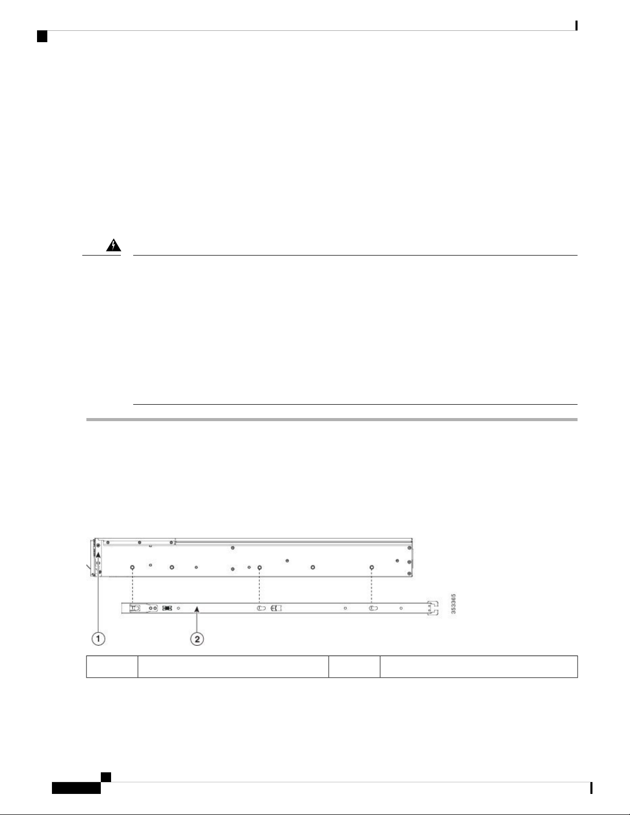
Figure 4: Attaching the Inner Rail to the Side of the Server
To prevent bodily injury when mounting or servicing this unit in a rack, you must take special
precautions to ensure that the system remains stable. The following guidelines are provided to ensure
your safety:
This unit should be mounted at the bottom of the rack if it is the only unit in the rack.
When mounting this unit in a partially filled rack, load the rack from the bottom to the top with the
heaviest component at the bottom of the rack.
If the rack is provided with stabilizing devices, install the stabilizers before mounting or servicing the
unit in the rack.
Statement 1006
side of the server.
has a metal clip that locks over the front peg.
Inner rail2Front of server1
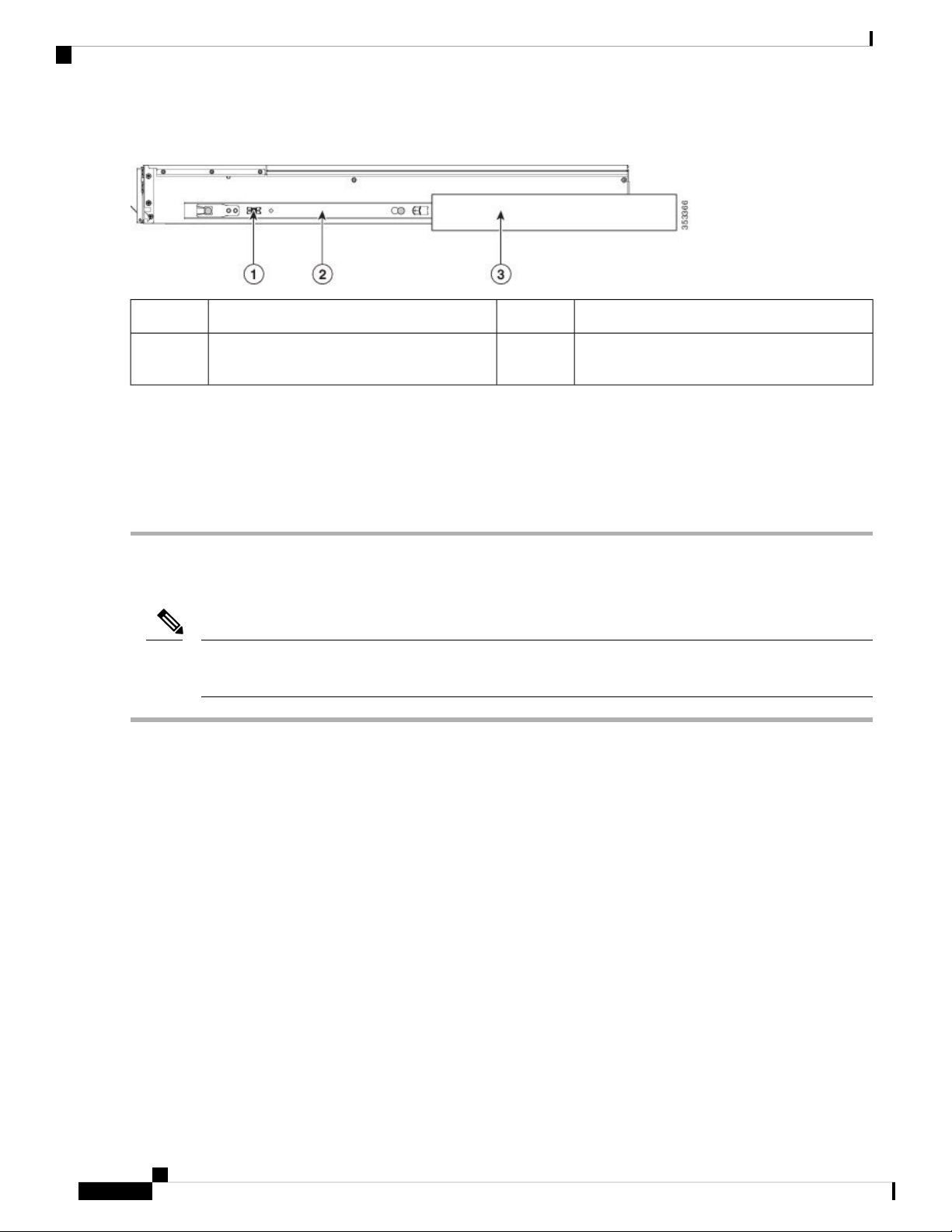
Step 2 Open the front securing plate on both slide-rail assemblies. The front end of the slide-rail assembly has a spring-loaded
securing plate that must be open before you can insert the mounting pegs into the rack-post holes.
Cisco APIC M3/L3 Server Installation and Service Guide
10
Page 19
Installing the Server
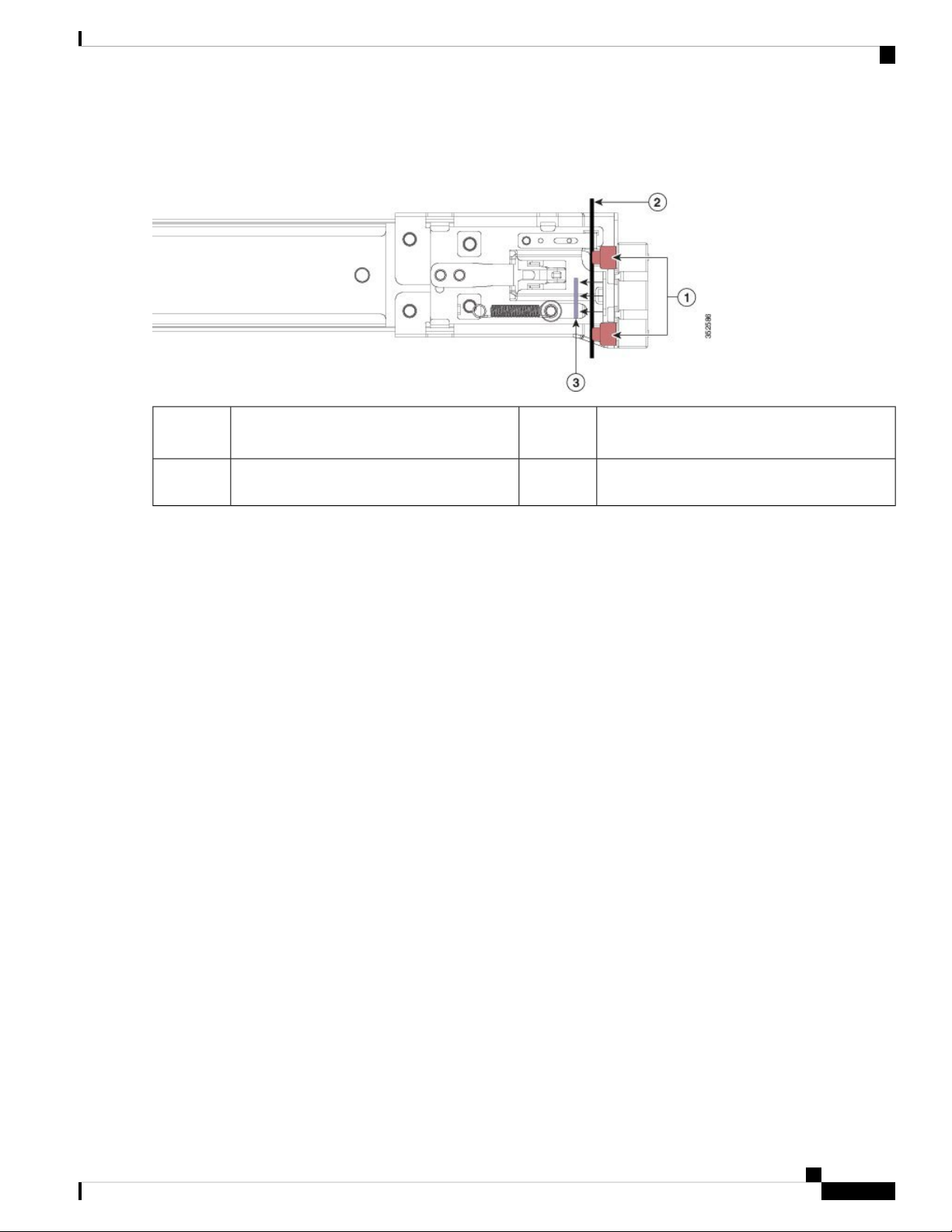
On the outside of the assembly, push the green-arrow button toward the rear to open the securing plate.
Figure 5: Front Securing Mechanism, Inside of Front End
Installing the Server in a Rack
2
securing plate
Step 3 Install the outer slide rails into the rack:
a) Align one slide-rail assembly front end with the front rack-post holes that you want to use.
The slide rail front-end wraps around the outside of the rack post and the mounting pegs enter the rack-post holes
from the outside-front.
Note
The rack post must be between the mounting pegs and the open securing plate.
b) Push the mounting pegs into the rack-post holes from the outside-front.
c) Press the securing plate release button, marked PUSH. The spring-loaded securing plate closes to lock the pegs in
place.
d) Adjust the slide-rail length, and then push the rear mounting pegs into the corresponding rear rack-post holes. The
slide rail must be level front-to-rear.
The rear mounting pegs enter the rear rack-post holes from the inside of the rack post.
e) Attach the second slide-rail assembly to the opposite side of the rack. Ensure that the two slide-rail assemblies are at
the same height and are level front-to-back.
f) Pull the inner slide rails on each assembly out toward the rack front until they hit the internal stops and lock in place.
3Front mounting pegs1
Securing plate shown pulled back to the open
position
-Rack post between mounting pegs and opened
Step 4 Insert the server into the slide rails:
Caution
This server can weigh up to 64 pounds (29 kilograms) when fully loaded with components. We recommend
that you use a minimum of two people or a mechanical lift when lifting the server. Attempting this procedure
alone could result in personal injury or equipment damage.
a) Align the rear ends of the inner rails that are attached to the server sides with the front ends of the empty slide rails
on the rack.
b) Push the inner rails into the slide rails on the rack until they stop at the internal stops.
c) Slide the inner-rail release clip toward the rear on both inner rails, and then continue pushing the server into the rack
until its front slam-latches engage with the rack posts.
Cisco APIC M3/L3 Server Installation and Service Guide
11
Page 20
Installing the Cable Management Arm (Optional)
Figure 6: Inner-Rail Release Clip
Installing the Server
Outer slide rail attached to rack post3Inner-rail release clip1
2
-Inner rail attached to server and inserted into
outer slide rail
Step 5 (Optional) Secure the server in the rack more permanently by using the two screws that are provided with the slide rails.
Perform this step if you plan to move the rack with servers installed.
With the server fully pushed into the slide rails, open a hinged slam latch lever on the front of the server and insert a
screw through the hole that is under the lever. The screw threads into the static part of the rail on the rack post and prevents
the server from being pulled out. Repeat for the opposite slam latch.
Installing the Cable Management Arm (Optional)
Note
The cable management arm (CMA) is reversible left-to-right. To reverse the CMA, see Reversing the Cable
Management Arm (Optional), on page 13 before installation.
Step 1 With the server pushed fully into the rack, slide the CMA tab of the CMA arm that is farthest from the server onto the
end of the stationary slide rail that is attached to the rack post. Slide the tab over the end of the rail until it clicks and
locks.
Cisco APIC M3/L3 Server Installation and Service Guide
12
Page 21

Installing the Server
Figure 7: Attaching the CMA to the Rear Ends of the Slide Rails
Reversing the Cable Management Arm (Optional)
1
3CMA tab on arm farthest from server attaches
to end of stationary outer slide rail.
2
CMA tab on width-adjustment slider attaches
to end of stationary outer slide rail.
Rear of server4CMA tab on arm closest to the server attaches
to end of inner slide rail attached to server.
Step 2 Slide the CMA tab that is closest to the server over the end of the inner rail that is attached to the server. Slide the tab
over the end of the rail until it clicks and locks
Step 3 Pull out the width-adjustment slider that is at the opposite end of the CMA assembly until it matches the width of your
rack.
Step 4 Slide the CMA tab that is at the end of the width-adjustment slider onto the end of the stationary slide rail that is attached
to the rack post. Slide the tab over the end of the rail until it clicks and locks.
Step 5 Open the hinged flap at the top of each plastic cable guide and route your cables through the cable guides as desired.
Reversing the Cable Management Arm (Optional)
Step 1 Rotate the entire CMA assembly 180 degrees, left-to-right. The plastic cable guides must remain pointing upward.
Step 2 Flip the tabs at the ends of the CMA arms so that they point toward the rear of the server.
Step 3 Pivot the tab that is at the end of the width-adjustment slider. Depress and hold the metal button on the outside of the tab
and pivot the tab 180 degrees so that it points toward the rear of the server.
Cisco APIC M3/L3 Server Installation and Service Guide
13
Page 22

Initial Server Setup
Figure 8: Reversing the CMA
Installing the Server
Initial Server Setup
Note
This section describes how to power on the server, assign an IP address, and connect to server management
when using the server in standalone mode.
Server Default Settings
The server is shipped with these default settings:
• The NIC mode is Shared LOM EXT.
Shared LOM EXT mode enables the 1-Gb/10-Gb Ethernet ports and the ports on any installed Cisco
virtual interface card (VIC) to access the Cisco Integrated Management Interface (Cisco IMC). If you
want to use the 10/100/1000 dedicated management ports to access Cisco IMC, you can connect to the
server and change the NIC mode as described in Setting Up the System With the Cisco IMC Configuration
Utility, on page 17.
Metal button on outside of tab2CMA tab on end of width-adjustment slider1
• The NIC redundancy is Active-Active. All Ethernet ports are utilized simultaneously.
• DHCP is enabled.
• IPv4 is enabled.
Cisco APIC M3/L3 Server Installation and Service Guide
14
Page 23

Installing the Server
Connecting to the Server Locally For Setup
Connection Methods
There are two methods for connecting to the system for initial setup:
• Local setup—Use this procedure if you want to connect a keyboard and monitor directly to the system
for setup. This procedure can use a KVM cable (Cisco PID N20-BKVM) or the ports on the rear of the
server.
• Remote setup—Use this procedure if you want to perform setup through your dedicated management
LAN.
Note
To configure the system remotely, you must have a DHCP server on the same
network as the system. Your DHCP server must be preconfigured with the range
of MAC addresses for this server node. The MAC address is printed on a label
that is on the pull-out asset tag on the front panel. This server node has a range
of six MAC addresses assigned to the Cisco IMC. The MAC address printed on
the label is the beginning of the range of six contiguous MAC addresses.
This section contains the following topics:
Connecting to the Server Locally For Setup
This procedure requires the following equipment:
• VGA monitor
• USB keyboard
• Either the supported Cisco KVM cable (Cisco PID N20-BKVM); or a USB cable and VGA DB-15 cable
Step 1 Attach a power cord to each power supply in your server, and then attach each power cord to a grounded power outlet.
Wait for approximately two minutes to let the server boot to standby power during the first bootup. You can verify system
power status by looking at the system Power Status LED on the front panel. The system is in standby power mode when
the LED is amber.
Step 2 Connect a USB keyboard and VGA monitor to the server using one of the following methods:
• Connect an optional KVM cable (Cisco PID N20-BKVM) to the KVM connector on the front panel. Connect your
USB keyboard and VGA monitor to the KVM cable.
• Connect a USB keyboard and VGA monitor to the corresponding connectors on the rear panel.
Step 3 Open the Cisco IMC Configuration Utility:
a) Press and hold the front panel power button for four seconds to boot the server.
b) During bootup, press F8 when prompted to open the Cisco IMC Configuration Utility.
Note
The first time that you enter the Cisco IMC Configuration Utility, you are prompted to change the default
password. The default password is password. The Strong Password feature is enabled.
The following are the requirements for Strong Password:
Cisco APIC M3/L3 Server Installation and Service Guide
15
Page 24

Connecting to the Server Remotely For Setup
• The password can have minimum 8 characters; maximum 14 characters.
• The password must not contain the user’s name.
• The password must contain characters from three of the following four categories:
• English uppercase letters (A through Z)
• English lowercase letters (a through z)
• Base 10 digits (0 through 9)
• Non-alphabetic characters !, @, #, $, %, ^, &, *, -, _, =, “
Step 4 Continue with Setting Up the System With the Cisco IMC Configuration Utility, on page 17.
Connecting to the Server Remotely For Setup
Installing the Server
This procedure requires the following equipment:
• One RJ-45 Ethernet cable that is connected to your management LAN.
Before you begin
Note
To configure the system remotely, you must have a DHCP server on the same network as the system. Your
DHCP server must be preconfigured with the range of MAC addresses for this server node. The MAC address
is printed on a label that is on the pull-out asset tag on the front panel. This server node has a range of six
MAC addresses assigned to the Cisco IMC. The MAC address printed on the label is the beginning of the
range of six contiguous MAC addresses.
Step 1 Attach a power cord to each power supply in your server, and then attach each power cord to a grounded power outlet.
Wait for approximately two minutes to let the server boot to standby power during the first bootup. You can verify system
power status by looking at the system Power Status LED on the front panel. The system is in standby power mode when
the LED is amber.
Step 2 Plug your management Ethernet cable into the dedicated management port on the rear panel.
Step 3 Allow your preconfigured DHCP server to assign an IP address to the server node.
Step 4 Use the assigned IP address to access and log in to the Cisco IMC for the server node. Consult with your DHCP server
administrator to determine the IP address.
Note
The default user name for the server is admin. The default password is password.
Step 5 From the Cisco IMC Server Summary page, click Launch KVM Console. A separate KVM console window opens.
Step 6 From the Cisco IMC Summary page, click Power Cycle Server. The system reboots.
Step 7 Select the KVM console window.
Note
16
The KVM console window must be the active window for the following keyboard actions to work.
Cisco APIC M3/L3 Server Installation and Service Guide
Page 25

Installing the Server
Setting Up the System With the Cisco IMC Configuration Utility
Step 8 When prompted, press F8 to enter the Cisco IMC Configuration Utility. This utility opens in the KVM console window.
Note
The first time that you enter the Cisco IMC Configuration Utility, you are prompted to change the default
password. The default password is password. The Strong Password feature is enabled.
The following are the requirements for Strong Password:
• The password can have minimum 8 characters; maximum 14 characters.
• The password must not contain the user’s name.
• The password must contain characters from three of the following four categories:
• English uppercase letters (A through Z)
• English lowercase letters (a through z)
• Base 10 digits (0 through 9)
• Non-alphabetic characters !, @, #, $, %, ^, &, *, -, _, =, “
Step 9 Continue with Setting Up the System With the Cisco IMC Configuration Utility, on page 17.
Setting Up the System With the Cisco IMC Configuration Utility
Before you begin
The following procedure is performed after you connect to the system and open the Cisco IMC Configuration
Utility.
Step 1 Set the NIC mode to choose which ports to use to access Cisco IMC for server management:
• Shared LOM EXT (default)—This is the shared LOM extended mode, the factory-default setting. With this mode,
the Shared LOM and Cisco Card interfaces are both enabled. You must select the default Active-Active NIC
redundancy setting in the following step.
In this NIC mode, DHCP replies are returned to both the shared LOM ports and the Cisco card ports. If the system
determines that the Cisco card connection is not getting its IP address from a Cisco UCS Manager system because
the server is in standalone mode, further DHCP requests from the Cisco card are disabled. Use the Cisco Card
NIC mode if you want to connect to Cisco IMC through a Cisco card in standalone mode.
• Shared LOM—The 1-Gb/10-Gb Ethernet ports are used to access Cisco IMC. You must select either the
Active-Active or Active-standby NIC redundancy setting in the following step.
• Dedicated—The dedicated management port is used to access Cisco IMC. You must select the None NIC redundancy
setting in the following step.
• Cisco Card—The ports on an installed Cisco UCS Virtual Interface Card (VIC) are used to access the Cisco IMC.
You must select either the Active-Active or Active-standby NIC redundancy setting in the following step.
See also the required VIC Slot setting below.
• VIC Slot—Only if you use the Cisco Card NIC mode, you must select this setting to match where your VIC is
installed. The choices are Riser1, Riser2, or Flex-LOM (the mLOM slot).
Cisco APIC M3/L3 Server Installation and Service Guide
17
Page 26

Setting Up the System With the Cisco IMC Configuration Utility
• If you select Riser1, you must install the VIC in slot 1.
• If you select Riser2, you must install the VIC in slot 2.
• If you select Flex-LOM, you must install an mLOM-style VIC in the mLOM slot.
Step 2 Set the NIC redundancy to your preference. This server has three possible NIC redundancy settings:
• None—The Ethernet ports operate independently and do not fail over if there is a problem. This setting can be
used only with the Dedicated NIC mode.
• Active-standby—If an active Ethernet port fails, traffic fails over to a standby port. Shared LOM and Cisco Card
modes can each use either Active-standby or Active-active settings.
• Active-active (default)—All Ethernet ports are utilized simultaneously. The Shared LOM EXT mode must use
only this NIC redundancy setting. Shared LOM and Cisco Card modes can each use either Active-standby or
Active-active settings.
Step 3 Choose whether to enable DHCP for dynamic network settings, or to enter static network settings.
Installing the Server
Note
Before you enable DHCP, you must preconfigure your DHCP server with the range of MAC addresses for
this server. The MAC address is printed on a label on the rear of the server. This server has a range of six
MAC addresses assigned to Cisco IMC. The MAC address printed on the label is the beginning of the range
of six contiguous MAC addresses.
The static IPv4 and IPv6 settings include the following:
• The Cisco IMC IP address.
For IPv6, valid values are 1 - 127.
• The gateway.
For IPv6, if you do not know the gateway, you can set it as none by entering :: (two colons).
• The preferred DNS server address.
For IPv6, you can set this as none by entering :: (two colons).
Step 4 (Optional) Make VLAN settings.
Step 5 Press F1 to go to the second settings window, then continue with the next step.
From the second window, you can press F2 to switch back to the first window.
Step 6 (Optional) Set a hostname for the server.
Step 7 (Optional) Enable dynamic DNS and set a dynamic DNS (DDNS) domain.
Step 8 (Optional) If you check the Factory Default check box, the server reverts to the factory defaults.
Step 9 (Optional) Set a default user password.
Note
The factory default username for the server is admin. The default password is password.
Step 10 (Optional) Enable auto-negotiation of port settings or set the port speed and duplex mode manually.
Note
Auto-negotiation is applicable only when you use the Dedicated NIC mode. Auto-negotiation sets the port
speed and duplex mode automatically based on the switch port to which the server is connected. If you disable
auto-negotiation, you must set the port speed and duplex mode manually.
Cisco APIC M3/L3 Server Installation and Service Guide
18
Page 27
Installing the Server
NIC Mode and NIC Redundancy Settings
Step 11 (Optional) Reset port profiles and the port name.
Step 12 Press F5 to refresh the settings that you made. You might have to wait about 45 seconds until the new settings appear
and the message, “Network settings configured” is displayed before you reboot the server in the next step.
Step 13 Press F10 to save your settings and reboot the server.
Note
If you chose to enable DHCP, the dynamically assigned IP and MAC addresses are displayed on the console
screen during bootup.
What to do next
Use a browser and the IP address of the Cisco IMC to connect to the Cisco IMC management interface. The
IP address is based upon the settings that you made (either a static address or the address assigned by your
DHCP server).
Note
The factory default username for the server is admin. The default password is password.
NIC Mode and NIC Redundancy Settings
Table 1: Valid NIC Redundancy Settings For Each NIC Mode
Valid NIC Redundancy SettingsNIC Mode
Active-activeShared LOM
EXT
NoneDedicated
Shared LOM
Active-active
Active-standby
Cisco Card
Active-active
Active-standby
This server has the following NIC mode settings that you can choose from:
• Shared LOM EXT (default)—This is the shared LOM extended mode, the factory-default setting. With
this mode, the Shared LOM and Cisco Card interfaces are both enabled. You must select the default
Active-Active NIC redundancy setting in the following step.
In this NIC mode, DHCP replies are returned to both the shared LOM ports and the Cisco card ports.
Use the Cisco Card NIC mode if you want to connect to Cisco IMC through a Cisco card in standalone
mode.
• Shared LOM—The 1-Gb/10-Gb Ethernet ports are used to access Cisco IMC. You must select either the
Active-Active or Active-standby NIC redundancy setting in the following step.
Cisco APIC M3/L3 Server Installation and Service Guide
19
Page 28

Updating the BIOS and Cisco IMC Firmware
• Dedicated—The dedicated management port is used to access Cisco IMC. You must select the None
NIC redundancy setting in the following step.
• Cisco Card—The ports on an installed Cisco UCS Virtual Interface Card (VIC) are used to access the
Cisco IMC. You must select either the Active-Active or Active-standby NIC redundancy setting in the
following step.
See also the required VIC Slot setting below.
• VIC Slot—Only if you use the Cisco Card NIC mode, you must select this setting to match where your
VIC is installed. The choices are Riser1, Riser2, or Flex-LOM (the mLOM slot).
• If you select Riser1, you must install the VIC in slot 1.
• If you select Riser2, you must install the VIC in slot 2.
• If you select Flex-LOM, you must install an mLOM-style VIC in the mLOM slot.
This server has the following NIC redundancy settings that you can choose from:
• None—The Ethernet ports operate independently and do not fail over if there is a problem. This setting
can be used only with the Dedicated NIC mode.
Installing the Server
• Active-standby—If an active Ethernet port fails, traffic fails over to a standby port. Shared LOM and
Cisco Card modes can each use either Active-standby or Active-active settings.
• Active-active (default)—All Ethernet ports are utilized simultaneously. The Shared LOM EXT mode
must use only this NIC redundancy setting. Shared LOM and Cisco Card modes can each use either
Active-standby or Active-active settings.
Updating the BIOS and Cisco IMC Firmware
Caution
When you upgrade the BIOS firmware, you must also upgrade the Cisco IMC firmware to the same version
or the server does not boot. Do not power off the server until the BIOS and Cisco IMC firmware are matching
or the server does not boot.
Cisco provides the Cisco Host Upgrade Utility to assist with simultaneously upgrading the BIOS, Cisco IMC,
and other firmware to compatible levels.
The server uses firmware obtained from and certified by Cisco. Cisco provides release notes with each firmware
image. There are several possible methods for updating the firmware:
• Recommended method for firmware update: Use the Cisco Host Upgrade Utility to simultaneously
upgrade the Cisco IMC, BIOS, and component firmware to compatible levels.
For the latest firmware release, see the Cisco Host Upgrade Utility Quick Reference Guide.
• You can upgrade the Cisco IMC and BIOS firmware by using the Cisco IMC GUI interface.
• You can upgrade the Cisco IMC and BIOS firmware by using the Cisco IMC CLI interface.
Cisco APIC M3/L3 Server Installation and Service Guide
20
Page 29

Installing the Server
Accessing the System BIOS
Step 1 Enter the BIOS Setup Utility by pressing the F2 key when prompted during bootup.
Accessing the System BIOS
Note
Step 2 Use the arrow keys to select the BIOS menu page.
Step 3 Highlight the field to be modified by using the arrow keys.
Step 4 Press Enter to select the field that you want to change, and then modify the value in the field.
Step 5 Press the right arrow key until the Exit menu screen is displayed.
Step 6 Follow the instructions on the Exit menu screen to save your changes and exit the setup utility (or press F10). You can
exit without saving changes by pressing Esc.
The version and build of the current BIOS are displayed on the Main page of the utility.
Smart Access Serial
This server supports the Smart Access Serial feature. This feature allows you to switch between host serial
and Cisco IMC CLI.
• This feature has the following requirements:
• A serial cable connection, which can use either the RJ-45 serial connector on the server rear panel,
or a DB-9 connection when using the KVM cable (Cisco PID N20-BKVM) on the front-panel KVM
console connector.
• Console redirection must be enabled in the server BIOS.
• Terminal type must be set to VT100+ or VTUFT8.
• Serial-over-LAN (SOL) must be disabled (SOL is disabled by default).
• To switch from host serial to Cisco IMC CLI, press Esc+9.
You must enter your Cisco IMC credentials to authenticate the connection.
• To switch from Cisco IMC CLI to host serial, press Esc+8.
Note
You cannot switch to Cisco IMC CLI if the serial-over-LAN (SOL) feature is
enabled.
• After a session is created, it is shown in the CLI or web GUI by the name serial.
Cisco APIC M3/L3 Server Installation and Service Guide
21
Page 30

Smart Access USB
Smart Access USB
This server supports the Smart Access USB feature. The board management controller (BMC) in this server
can accept a USB mass storage device and access the data on it. This feature allows you to use the front-panel
USB device as a medium to transfer data between the BMC and the user without need for network connectivity.
This can be useful, for example, when remote BMC interfaces are not yet available, or are not accessible due
to network misconfiguration.
• This feature has the following requirements:
• The KVM cable (Cisco PID N20-BKVM) connected to the front panel KVM console connector.
• A USB storage device connected to one of the USB 2.0 connectors on the KVM cable. The USB
device must draw less than 500 mA to avoid disconnect by the current-protection circuit.
Note
Installing the Server
Any mouse or keyboard that is connected to the KVM cable is disconnected when
you enable Smart Access USB.
• You can use USB 3.0-based devices, but they will operate at USB 2.0 speed.
• We recommend that the USB device have only one partition.
• The file system formats supported are: FAT16, FAT32, MSDOS, EXT2, EXT3, and EXT4. NTFS
is not supported.
• The front-panel KVM connector has been designed to switch the USB port between Host OS and BMC.
• Smart Access USB can be enabled or disabled using any of the BMC user interfaces. For example, you
can use the Cisco IMC Configuration Utility that is accessed by pressing F8 when prompted during
bootup.
• Enabled: the front-panel USB device is connected to the BMC.
• Disabled: the front-panel USB device is connected to the host.
• In a case where no management network is available to connect remotely to Cisco IMC, a Device Firmware
Update (DFU) shell over serial cable can be used to generate and download technical support files to the
USB device that is attached to front panel USB port.
Cisco APIC M3/L3 Server Installation and Service Guide
22
Page 31

Maintaining the Server
• Status LEDs and Buttons, on page 23
• Preparing For Component Installation, on page 28
• Removing and Replacing Components, on page 32
• Service Headers and Jumpers, on page 85
Status LEDs and Buttons
This section contains information for interpreting front, rear, and internal LED states.
Front-Panel LEDs
Figure 9: Front Panel LEDs
CHAPTER 3
Table 2: Front Panel LEDs, Definition of States
StatesLED Name
Cisco APIC M3/L3 Server Installation and Service Guide
23
Page 32

Front-Panel LEDs
Maintaining the Server
1
SAS
SAS
1
NVMe
SAS/SATA drive fault
Note
NVMe solid state drive (SSD) drive tray
LEDs have different behavior than
SAS/SATA drive trays.
SAS/SATA drive activity LED2
NVMe SSD drive fault
Note
NVMe solid state drive (SSD) drive tray
LEDs have different behavior than
SAS/SATA drive trays.
• Off—The hard drive is operating properly.
• Amber—Drive fault detected.
• Amber, blinking—The device is rebuilding.
• Amber, blinking with one-second interval—Drive
locate function activated in the software.
• Off—There is no hard drive in the hard drive tray (no
access, no fault).
• Green—The hard drive is ready.
• Green, blinking—The hard drive is reading or writing
data.
• Off—The drive is not in use and can be safely
removed.
• Green—The drive is in use and functioning properly.
• Green, blinking—the driver is initializing following
insertion or the driver is unloading following an eject
command.
• Amber—The drive has failed.
NVMe
• Amber, blinking—A drive Locate command has been
issued in the software.
NVMe SSD activity2
• Off—No drive activity.
• Green, blinking—There is drive activity.
Power button/LED3
• Off—There is no AC power to the server.
• Amber—The server is in standby power mode. Power
is supplied only to the Cisco IMC and some
motherboard functions.
• Green—The server is in main power mode. Power is
supplied to all server components.
Unit identification4
• Off—The unit identification function is not in use.
• Blue, blinking—The unit identification function is
activated.
Cisco APIC M3/L3 Server Installation and Service Guide
24
Page 33

Maintaining the Server
Front-Panel LEDs
System health5
• Green—The server is running in normal operating
condition.
• Green, blinking—The server is performing system
initialization and memory check.
• Amber, steady—The server is in a degraded
operational state (minor fault). For example:
• Power supply redundancy is lost.
• CPUs are mismatched.
• At least one CPU is faulty.
• At least one DIMM is faulty.
• At least one drive in a RAID configuration failed.
• Amber, 2 blinks—There is a major fault with the
system board.
• Amber, 3 blinks—There is a major fault with the
memory DIMMs.
• Amber, 4 blinks—There is a major fault with the
CPUs.
Power supply status6
• Green—All power supplies are operating normally.
• Amber, steady—One or more power supplies are in
a degraded operational state.
• Amber, blinking—One or more power supplies are
in a critical fault state.
Fan status7
• Green—All fan modules are operating properly.
• Amber, blinking—One or more fan modules breached
the non-recoverable threshold.
Network link activity8
• Off—The Ethernet LOM port link is idle.
• Green—One or more Ethernet LOM ports are
link-active, but there is no activity.
• Green, blinking—One or more Ethernet LOM ports
are link-active, with activity.
Temperature status9
• Green—The server is operating at normal temperature.
• Amber, steady—One or more temperature sensors
breached the critical threshold.
• Amber, blinking—One or more temperature sensors
breached the non-recoverable threshold.
Cisco APIC M3/L3 Server Installation and Service Guide
25
Page 34

Rear-Panel LEDs
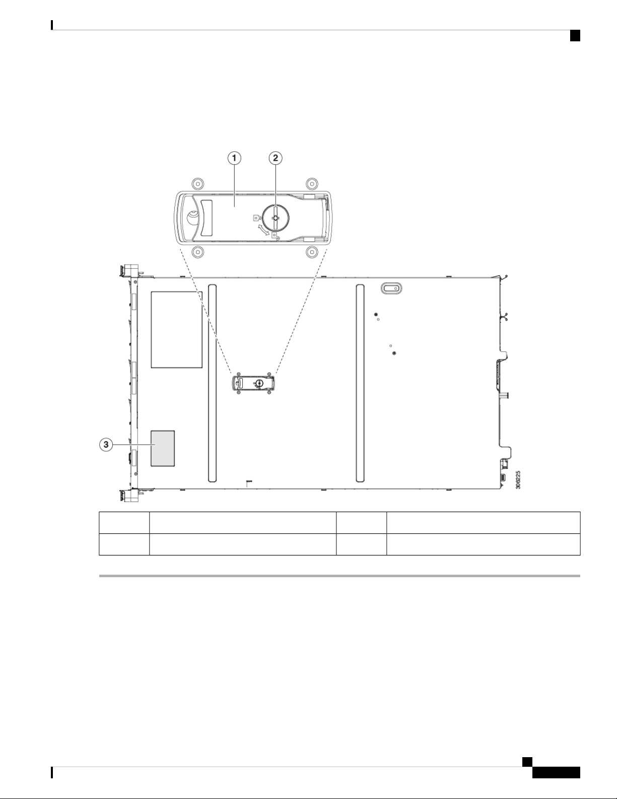
Rear-Panel LEDs
Figure 10: Rear Panel LEDs
Table 3: Rear Panel LEDs, Definition of States
Maintaining the Server
StatesLED Name
1
1-Gb/10-Gb Ethernet link speed (on both LAN1 and
LAN2)
• Off—Link speed is 100 Mbps.
• Amber—Link speed is 1 Gbps.
• Green—Link speed is 10 Gbps.
2
1-Gb/10-Gb Ethernet link status (on both LAN1 and
LAN2)
• Off—No link is present.
• Green—Link is active.
• Green, blinking—Traffic is present on the active link.
1-Gb Ethernet dedicated management link speed3
• Off—Link speed is 10 Mbps.
• Amber—Link speed is 100 Mbps.
• Green—Link speed is 1 Gbps.
1-Gb Ethernet dedicated management link status4
• Off—No link is present.
• Green—Link is active.
• Green, blinking—Traffic is present on the active link.
Rear unit identification5
• Off—The unit identification function is not in use.
• Blue, blinking—The unit identification function is
activated.
Cisco APIC M3/L3 Server Installation and Service Guide
26
Page 35

Maintaining the Server
Internal Diagnostic LEDs
Power supply status (one LED each power supply unit)6
AC power supplies:
• Off—No AC input (12 V main power off, 12 V
standby power off).
• Green, blinking—12 V main power off; 12 V standby
power on.
• Green, solid—12 V main power on; 12 V standby
power on.
• Amber, blinking—Warning threshold detected but 12
V main power on.
• Amber, solid—Critical error detected; 12 V main
power off (for example, over-current, over-voltage,
or over-temperature failure).
DC power supplies:
• Off—No DC input (12 V main power off, 12 V
standby power off).
• Green, blinking—12 V main power off; 12 V standby
power on.
• Green, solid—12 V main power on; 12 V standby
power on.
Internal Diagnostic LEDs
The server has internal fault LEDs for CPUs, DIMMs, and fan modules.
• Amber, blinking—Warning threshold detected but 12
V main power on.
• Amber, solid—Critical error detected; 12 V main
power off (for example, over-current, over-voltage,
or over-temperature failure).
Cisco APIC M3/L3 Server Installation and Service Guide
27
Page 36

Preparing For Component Installation
Figure 11: Internal Diagnostic LED Locations
Maintaining the Server
1
connector on the motherboard)
• Amber—Fan has a fault or is not fully seated.
• Green—Fan is OK.
2
the motherboard).
These LEDs operate only when the server is in
standby power mode.
• Amber—CPU has a fault.
• Off—CPU is OK.
3Fan module fault LEDs (one behind each fan
-CPU fault LEDs (one behind each CPU socket on
Preparing For Component Installation
This section includes information and tasks that help prepare the server for component installation.
DIMM fault LEDs (one behind each DIMM socket
on the motherboard)
These LEDs operate only when the server is in
standby power mode.
• Amber—DIMM has a fault.
• Off—DIMM is OK.
Cisco APIC M3/L3 Server Installation and Service Guide
28
Page 37

Maintaining the Server
Required Equipment For Service Procedures
The following tools and equipment are used to perform the procedures in this chapter:
• T-30 Torx driver (supplied with replacement CPUs for heatsink removal)
• #1 flat-head screwdriver (supplied with replacement CPUs for heatsink removal)
• #1 Phillips-head screwdriver (for M.2 SSD and intrusion switch replacement)
• Electrostatic discharge (ESD) strap or other grounding equipment such as a grounded mat
Shutting Down and Removing Power From the Server
The server can run in either of two power modes:
• Main power mode—Power is supplied to all server components and any operating system on your drives
can run.
• Standby power mode—Power is supplied only to the service processor and certain components. It is safe
for the operating system and data to remove power cords from the server in this mode.
Required Equipment For Service Procedures
Caution
After a server is shut down to standby power, electric current is still present in the server. To completely
remove power as directed in some service procedures, you must disconnect all power cords from all power
supplies in the server.
You can shut down the server by using the front-panel power button or the software management interfaces.
Shutting Down Using the Power Button
Step 1 Check the color of the Power button/LED:
• Amber—The server is already in standby mode and you can safely remove power.
• Green—The server is in main power mode and must be shut down before you can safely remove power.
Step 2 Invoke either a graceful shutdown or a hard shutdown:
Caution
To avoid data loss or damage to your operating system, you should always invoke a graceful shutdown of the
operating system.
• Graceful shutdown—Press and release the Power button. The operating system performs a graceful shutdown and
the server goes to standby mode, which is indicated by an amber Power button/LED.
• Emergency shutdown—Press and hold the Power button for 4 seconds to force the main power off and immediately
enter standby mode.
Step 3 If a service procedure instructs you to completely remove power from the server, disconnect all power cords from the
power supplies in the server.
Cisco APIC M3/L3 Server Installation and Service Guide
29
Page 38

Maintaining the Server
Shutting Down Using The Cisco IMC GUI
Shutting Down Using The Cisco IMC GUI
You must log in with user or admin privileges to perform this task.
Step 1 In the Navigation pane, click the Server tab.
Step 2 On the Server tab, click Summary.
Step 3 In the Actions area, click Power Off Server.
Step 4 Click OK.
The operating system performs a graceful shutdown and the server goes to standby mode, which is indicated by an amber
Power button/LED.
Step 5 If a service procedure instructs you to completely remove power from the server, disconnect all power cords from the
power supplies in the server.
Shutting Down Using The Cisco IMC CLI
You must log in with user or admin privileges to perform this task.
Step 1 At the server prompt, enter:
Example:
server# scope chassis
Step 2 At the chassis prompt, enter:
Example:
server/chassis# power shutdown
The operating system performs a graceful shutdown and the server goes to standby mode, which is indicated by an amber
Power button/LED.
Step 3 If a service procedure instructs you to completely remove power from the server, disconnect all power cords from the
power supplies in the server.
Removing the Server Top Cover
Step 1 Remove the top cover:
a) If the cover latch is locked, use a screwdriver to turn the lock 90-degrees counterclockwise to unlock it.
b) Lift on the end of the latch that has the green finger grip. The cover is pushed back to the open position as you lift
the latch.
c) Lift the top cover straight up from the server and set it aside.
Step 2 Replace the top cover:
a) With the latch in the fully open position, place the cover on top of the server about one-half inch (1.27 cm) behind
the lip of the front cover panel. The opening in the latch should fit over the peg that sticks up from the fan tray.
Cisco APIC M3/L3 Server Installation and Service Guide
30
Page 39
Maintaining the Server
b) Press the cover latch down to the closed position. The cover is pushed forward to the closed position as you push
down the latch.
c) If desired, lock the latch by using a screwdriver to turn the lock 90-degrees clockwise.
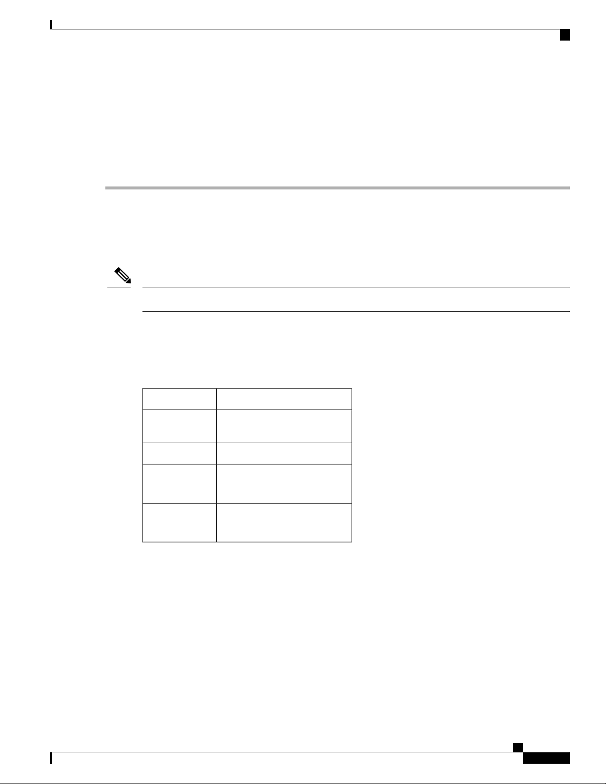
Figure 12: Removing the Top Cover
Serial Number Location
Serial Number Location
The serial number for the server is printed on a label on the top of the server, near the front.
Hot Swap vs Hot Plug
Some components can be removed and replaced without shutting down and removing power from the server.
This type of replacement has two varieties: hot-swap and hot-plug.
Locking cover latch2Top cover1
Serial number label location3
Cisco APIC M3/L3 Server Installation and Service Guide
31
Page 40

Removing and Replacing Components
• Hot-swap replacement—You do not have to shut down the component in the software or operating
system. This applies to the following components:
• SAS/SATA hard drives
• SAS/SATA solid state drives
• Cooling fan modules
• Power supplies (when redundant as 1+1)
• Hot-plug replacement—You must take the component offline before removing it for the following
component:
• NVMe PCIe solid state drives
Removing and Replacing Components
Maintaining the Server
Warning
Caution
Blank faceplates and cover panels serve three important functions: they prevent exposure to hazardous
voltages and currents inside the chassis; they contain electromagnetic interference (EMI) that might
disrupt other equipment; and they direct the flow of cooling air through the chassis. Do not operate the
system unless all cards, faceplates, front covers, and rear covers are in place.
Statement 1029
When handling server components, handle them only by carrier edges and use an electrostatic discharge (ESD)
wrist-strap or other grounding device to avoid damage.
Tip
You can press the unit identification button on the front panel or rear panel to turn on a flashing, blue unit
identification LED on both the front and rear panels of the server. This button allows you to locate the specific
server that you are servicing when you go to the opposite side of the rack. You can also activate these LEDs
remotely by using the Cisco IMC interface.
This section describes how to install and replace server components.
Serviceable Component Locations
This topic shows the locations of the field-replaceable components and service-related items. The view in the
following figure shows the server with the top cover removed.
Cisco APIC M3/L3 Server Installation and Service Guide
32
Page 41

Maintaining the Server
Figure 13: Cisco APIC M3 and L3 Server, Serviceable Component Locations
Serviceable Component Locations
1
RTC battery, vertical socket9Front-loading drive bays 1–10 support SAS/SATA
drives.
10Cooling fan modules (seven, hot-swappable)2
Power supplies (hot-swappable when redundant as
1+1)
11Supercap unit mounting bracket (RAID backup)3
Trusted platform module (TPM) socket on
motherboard (not visible in this view)
12DIMM sockets on motherboard (12 per CPU)4
PCIe riser 1/slot 1 (half-height, x16 lane)
Includes PCIe cable connectors for front-loading
NVMe SSDs (x8 lane)
13CPUs and heatsinks (up to two)5
VIC 1455 with external 10/25-Gigabit Ethernet ports
(4)
6
Available (empty) PCIe slot14Mini storage module socket
Supports either an SD card module with two SD
card slots; or an M.2 module with two NVMe or
SATA M.2 SSD slots.
15Chassis intrusion switch (optional)7
PCIe cable connectors for front-loading NVMe SSDs
on PCIe riser 2
Micro-SD card socket on PCIe riser 116Internal USB 3.0 port on motherboard8
Cisco APIC M3/L3 Server Installation and Service Guide
33
Page 42

Replacing SAS/SATA Hard Drives or Solid State Drives
Replacing SAS/SATA Hard Drives or Solid State Drives
Note
You do not have to shut down the server or drive to replace SAS/SATA hard drives or SSDs because they
are hot-swappable. To replace an NVMe PCIe SSD drive, which must be shut down before removal, see
Replacing a Front-Loading NVMe SSD, on page 36.
SAS/SATA Drive Population Guidelines
The server is orderable in three different versions, each with a different front panel/drive-backplane
configuration.
Drive bay numbering is shown in the following figures.
Figure 14: Small Form-Factor Drive Versions, Drive Bay Numbering
Maintaining the Server
Observe these drive population guidelines for optimum performance:
• When populating drives, add drives to the lowest-numbered bays first.
Note
For diagrams of which drive bays are controlled by particular controller cables
on the backplane, see Storage Controller and Backplane Connectors, on page 102.
For example, in a SFF 10-drive server, drive bays 5 and 10 cannot be controlled
by embedded SATA RAID.
• Keep an empty drive blanking tray in any unused bays to ensure proper airflow.
• You can mix SAS/SATA hard drives and SAS/SATA SSDs in the same server. However, you cannot
configure a logical volume (virtual drive) that contains a mix of hard drives and SSDs. That is, when
you create a logical volume, it must contain all SAS/SATA hard drives or all SAS/SATA SSDs.
4K Sector Format SAS/SATA Drives Considerations
• You must boot 4K sector format drives in UEFI mode, not legacy mode. See the procedures in this
section.
• Do not configure 4K sector format and 512-byte sector format drives as part of the same RAID volume.
• Operating system support on 4K sector drives is as follows: Windows: Win2012 and Win2012R2; Linux:
RHEL 6.5, 6.6, 6.7, 7.0, 7.2; SLES 11 SP3, and SLES 12. ESXi/Vmware is not supported.
Step 1
Procedure
PurposeCommand or Action
Cisco APIC M3/L3 Server Installation and Service Guide
34
Page 43

Maintaining the Server
Setting Up UEFI Mode Booting in the BIOS Setup Utility
Setting Up UEFI Mode Booting in the BIOS Setup Utility
Step 1 Enter the BIOS setup utility by pressing the F2 key when prompted during bootup.
Step 2 Go to the Boot Options tab.
Step 3 Set UEFI Boot Options to Enabled.
Step 4 Under Boot Option Priorities, set your OS installation media (such as a virtual DVD) as your Boot Option #1.
Step 5 Go to the Advanced tab.
Step 6 Select LOM and PCIe Slot Configuration.
Step 7 Set the PCIe Slot ID: HBA Option ROM to UEFI Only.
Step 8 Press F10 to save changes and exit the BIOS setup utility. Allow the server to reboot.
Step 9 After the OS installs, verify the installation:
a) Enter the BIOS setup utility by pressing the F2 key when prompted during bootup.
b) Go to the Boot Options tab.
c) Under Boot Option Priorities, verify that the OS you installed is listed as your Boot Option #1.
Setting Up UEFI Mode Booting in the Cisco IMC GUI
Step 1 Use a web browser and the IP address of the server to log into the Cisco IMC GUI management interface.
Step 2 Navigate to Server > BIOS.
Step 3 Under Actions, click Configure BIOS.
Step 4 In the Configure BIOS Parameters dialog, select the Advanced tab.
Step 5 Go to the LOM and PCIe Slot Configuration section.
Step 6 Set the PCIe Slot: HBA Option ROM to UEFI Only.
Step 7 Click Save Changes. The dialog closes.
Step 8 Under BIOS Properties, set Configured Boot Order to UEFI.
Step 9 Under Actions, click Configure Boot Order.
Step 10 In the Configure Boot Order dialog, click Add Local HDD.
Step 11 In the Add Local HDD dialog, enter the information for the 4K sector format drive and make it first in the boot order.
Step 12 Save changes and reboot the server. The changes you made will be visible after the system reboots.
Replacing a SAS/SATA Drive
Step 1 Remove the drive that you are replacing or remove a blank drive tray from the bay:
a) Press the release button on the face of the drive tray.
b) Grasp and open the ejector lever and then pull the drive tray out of the slot.
c) If you are replacing an existing drive, remove the four drive-tray screws that secure the drive to the tray and then lift
the drive out of the tray.
Step 2 Install a new drive:
a) Place a new drive in the empty drive tray and install the four drive-tray screws.
Cisco APIC M3/L3 Server Installation and Service Guide
35
Page 44

Replacing a Front-Loading NVMe SSD
b) With the ejector lever on the drive tray open, insert the drive tray into the empty drive bay.
c) Push the tray into the slot until it touches the backplane, and then close the ejector lever to lock the drive in place.
Figure 15: Replacing a Drive in a Drive Tray
Maintaining the Server
Replacing a Front-Loading NVMe SSD
This section is for replacing 2.5-inch or 3.5-inch form-factor NVMe solid-state drives (SSDs) in front-panel
drive bays. To replace HHHL form-factor NVMe SSDs in the PCIe slots, see Replacing HHHL Form-Factor
NVMe Solid State Drives.
Front-Loading NVMe SSD Population Guidelines
The front drive bay supports 2.5- inch NVMe SSDs.
Cisco APIC M3/L3 Server Installation and Service Guide
36
Drive tray screws (two on each side)3Ejector lever1
Drive removed from drive tray4Release button2
Page 45

Maintaining the Server
Front-Loading NVME SSD Requirements and Restrictions
Observe these requirements:
• The server must have two CPUs. PCIe riser 2 is not available in a single-CPU system. PCIe riser 2 has
connectors for the cable that connects to the front-panel drive backplane.
• PCIe cable CBL-NVME-C220FF. This is the cable that carries the PCIe signal from the front-panel drive
backplane to PCIe riser 2. This cable is for all versions of this server.
• Hot-plug support must be enabled in the system BIOS. If you ordered the system with NVMe drives,
hot-plug support is enabled at the factory.
• The NVMe-optimized, SFF 10-drive version, APIC-SERVER-M3 and APIC-SERVER-L3, support
NVMe drives only. This version of the server comes with an NVMe-switch card factory-installed in the
internal mRAID riser for support of NVMe drives in slots 3 - 10. The NVMe drives in slots 1 and 2 are
supported by PCIe riser 2. The NVMe switch card is not orderable separately.
Observe these restrictions:
• NVMe SFF 2.5-inch SSDs support booting only in UEFI mode. Legacy boot is not supported.
Front-Loading NVME SSD Requirements and Restrictions
• You cannot control NVMe PCIe SSDs with a SAS RAID controller because NVMe SSDs interface with
the server via the PCIe bus.
• UEFI boot is supported in all supported operating systems. Hot-insertion and hot-removal are supported
in all supported operating systems except VMWare ESXi.
Enabling Hot-Plug Support in the System BIOS
Hot-plug (OS-informed hot-insertion and hot-removal) is disabled in the system BIOS by default.
• If the system was ordered with NVMe PCIe SSDs, the setting was enabled at the factory. No action is
required.
• If you are adding NVMe PCIe SSDs after-factory, you must enable hot-plug support in the BIOS. See
the following procedures.
Enabling Hot-Plug Support Using the BIOS Setup Utility
Step 1 Enter the BIOS setup utility by pressing the F2 key when prompted during bootup.
Step 2 Navigate to Advanced > PCI Subsystem Settings > NVMe SSD Hot-Plug Support.
Step 3 Set the value to Enabled.
Step 4 Save your changes and exit the utility.
Enabling Hot-Plug Support Using the Cisco IMC GUI
Step 1 Use a browser to log in to the Cisco IMC GUI for the server.
Step 2 Navigate to Compute > BIOS > Advanced > PCI Configuration.
Step 3 Set NVME SSD Hot-Plug Support to Enabled.
Cisco APIC M3/L3 Server Installation and Service Guide
37
Page 46

Replacing a Front-Loading NVMe SSD
Step 4 Save your changes.
Replacing a Front-Loading NVMe SSD
This topic describes how to replace 2.5-inch form-factor NVMe SSDs in the front-panel drive bays.
Note
OS-surprise removal is not supported. OS-informed hot-insertion and hot-removal are supported on all
supported operating systems except VMware ESXi.
Note
OS-informed hot-insertion and hot-removal must be enabled in the system BIOS. See Enabling Hot-Plug
Support in the System BIOS, on page 37.
Maintaining the Server
Step 1 Remove an existing front-loading NVMe SSD:
a) Shut down the NVMe SSD to initiate an OS-informed removal. Use your operating system interface to shut down
the drive, and then observe the drive-tray LED:
• Green—The drive is in use and functioning properly. Do not remove.
• Green, blinking—the driver is unloading following a shutdown command. Do not remove.
• Off—The drive is not in use and can be safely removed.
b) Press the release button on the face of the drive tray.
c) Grasp and open the ejector lever and then pull the drive tray out of the slot.
d) Remove the four drive tray screws that secure the SSD to the tray and then lift the SSD out of the tray.
Note
If this is the first time that front-loading NVMe SSDs are being installed in the server, you must install PCIe
cable CBL-NVME-C220FF before installing the drive.
Step 2 Install a new front-loading NVMe SSD:
a) Place a new SSD in the empty drive tray and install the four drive-tray screws.
b) With the ejector lever on the drive tray open, insert the drive tray into the empty drive bay.
c) Push the tray into the slot until it touches the backplane, and then close the ejector lever to lock the drive in place.
Step 3 Observe the drive-tray LED and wait until it returns to solid green before accessing the drive:
• Off—The drive is not in use.
• Green, blinking—the driver is initializing following hot-plug insertion.
• Green—The drive is in use and functioning properly.
Cisco APIC M3/L3 Server Installation and Service Guide
38
Page 47

Maintaining the Server
Figure 16: Replacing a Drive in a Drive Tray
Installing a PCIe Cable For Front-Loading NVMe SSDs
Installing a PCIe Cable For Front-Loading NVMe SSDs
The front-loading NVMe SSDs interface with the server via the PCIe bus. Cable CBL-NVME-C220FF
connects the front-panel drive backplane to the PCIe riser 2 board on the PCIe riser assembly.
• If the server was ordered with 2.5-inch form-factor NVMe SSDs, this cable was preinstalled at the factory.
No action is required.
• If you are adding 2.5-inch form-factor NVMe SSDs for the first time, you must order and install the
cable as described in the following procedure.
Cisco APIC M3/L3 Server Installation and Service Guide
Drive tray screws (two on each side)3Ejector lever1
Drive removed from drive tray4Release button2
39
Page 48

Maintaining the Server
Replacing HHHL Form-Factor NVMe Solid State Drives
Step 1 Connect the two connectors on one end of the cable to the PCIE-A1 and PCIE-A2 connectors on the drive backplane.
Step 2 Route the cables through the chassis cable guides to the rear of the server as shown below.
Step 3 Connect the single connector on the other end of the cable to the PCIE-FRONT connector on PCIe riser 2.
Figure 17: PCIe Cabling to Drive Backplane
Replacing HHHL Form-Factor NVMe Solid State Drives
This section is for replacing half-height, half-length (HHHL) form-factor NVMe SSDs in the PCIe slots. To
replace 2.5-inch NVMe SSDs in the front-panel drive bays, see Replacing a Front-Loading NVMe SSD, on
page 36.
HHHL SSD Population Guidelines
Observe the following population guidelines when installing HHHL form-factor NVMe SSDs:
• Two-CPU systems—You can populate up to 2 HHHL form-factor SSDs, using PCIe slots 1 – 2.
• One-CPU systems—In a single-CPU system, PCIe riser 2/slot 2 is not available. Therefore, the maximum
number of HHHL form-factor SSDs you can populate is 1, in PCIe slot 1.
HHHL Form-Factor NVME SSD Requirements and Restrictions
Observe these requirements:
• All versions of the server support HHHL form-factor NVMe SSDs.
Observe these restrictions:
Cisco APIC M3/L3 Server Installation and Service Guide
40
Page 49

Maintaining the Server
• You cannot boot from an HHHL form-factor NVMe SSD.
• You cannot control HHHL NVMe SSDs with a SAS RAID controller because NVMe SSDs interface
with the server via the PCIe bus.
• You can combine NVMe SFF 2.5-inch SSDs and HHHL form-factor SSDs in the same system, but the
same partner brand must be used. For example, two Intel NVMe SFF 2.5-inch SSDs and two HGST
HHHL form-factor SSDs is an invalid configuration. A valid configuration is two HGST NVMe SFF
2.5-inch SSDs and two HGST HHHL form-factor SSDs.
Replacing an HHHL Form-Factor NVMe SSD
Replacing an HHHL Form-Factor NVMe SSD
Note
In a single-CPU server, PCIe riser 2 (PCIe slot 2) is not available.
Step 1 Remove an existing HHHL form-factor NVME SSD (or a blank filler panel) from the PCIe riser:
a) Shut down and remove power from the server as described in Shutting Down and Removing Power From the Server,
on page 29.
b) Slide the server out the front of the rack far enough so that you can remove the top cover. You might have to detach
cables from the rear panel to provide clearance.
Caution
If you cannot safely view and access the component, remove the server from the rack.
c) Remove the top cover from the server as described in Removing the Server Top Cover, on page 30.
d) Use two hands to grasp the external riser handle and the blue area at the front of the riser.
e) Open the hinged, plastic card retainer that secures the rear-panel tab of the card.
f) Pull evenly on both ends of the HHHL form-factor NVME SSD to remove it from the socket on the PCIe riser.
If the riser has no SSD, remove the blanking panel from the rear opening of the riser.
Step 2 Install a new HHHL form-factor NVME SSD:
a) Open the hinged, plastic card retainer.
b) Align the new SSD with the empty socket on the PCIe riser.
c) Push down evenly on both ends of the card until it is fully seated in the socket.
d) Ensure that the SSD’s rear panel tab sits flat against the riser rear-panel opening and then close the hinged card retainer
over the card’s rear-panel tab.
e) Position the PCIe riser over its two sockets on the motherboard and over the chassis alignment channels.
f) Carefully push down on both ends of the PCIe riser to fully engage its two connectors with the two sockets on the
motherboard.
g) Replace the top cover to the server.
h) Replace the server in the rack, replace cables, and then fully power on the server by pressing the Power button.
Cisco APIC M3/L3 Server Installation and Service Guide
41
Page 50

Replacing Fan Modules
Figure 18: PCIe Riser Assembly
Maintaining the Server
PCIe slot 2 rear-panel opening3
Replacing Fan Modules
The seven fan modules in the server are numbered as shown in Serviceable Component Locations, on page
3.
Tip
Each fan module has a fault LED next to the fan connector on the motherboard. This LED lights green when
the fan is correctly seated and is operating OK. The LED lights amber when the fan has a fault or is not
correctly seated.
Hinged card retainer (one each slot)4PCIe slot 1 rear-panel opening1
5External riser handle2
PCIe connector for cable that supports
front-panel NVMe SSDs
Cisco APIC M3/L3 Server Installation and Service Guide
42
Page 51

Maintaining the Server
Replacing Memory DIMMs
Caution
You do not have to shut down or remove power from the server to replace fan modules because they are hotswappable. However, to maintain proper cooling, do not operate the server for more than one minute with
any fan module removed.
Step 1 Remove an existing fan module:
a) Slide the server out the front of the rack far enough so that you can remove the top cover. You might have to detach
cables from the rear panel to provide clearance.
Caution
If you cannot safely view and access the component, remove the server from the rack.
b) Remove the top cover from the server as described in Removing the Server Top Cover, on page 30.
c) Grasp the fan module at its front and rear finger-grips. Lift straight up to disengage its connector from the motherboard.
Step 2 Install a new fan module:
a) Set the new fan module in place. The arrow printed on the top of the fan module should point toward the rear of the
server.
b) Press down gently on the fan module to fully engage it with the connector on the motherboard.
c) Replace the top cover to the server.
d) Replace the server in the rack, replace cables, and then fully power on the server by pressing the Power button.
Replacing Memory DIMMs
Caution
Caution
DIMMs and their sockets are fragile and must be handled with care to avoid damage during installation.
Cisco does not support third-party DIMMs. Using non-Cisco DIMMs in the server might result in system
problems or damage to the motherboard.
Note
To ensure the best server performance, it is important that you are familiar with memory performance guidelines
and population rules before you install or replace DIMMs.
DIMM Population Rules and Memory Performance Guidelines
This topic describes the rules and guidelines for maximum memory performance.
DIMM Slot Numbering
The following figure shows the numbering of the DIMM slots on the motherboard.
Cisco APIC M3/L3 Server Installation and Service Guide
43
Page 52

DIMM Population Rules and Memory Performance Guidelines
Figure 19: DIMM Slot Numbering
DIMM Population Rules
Observe the following guidelines when installing or replacing DIMMs for maximum performance:
• Each CPU supports six memory channels.
• CPU 1 supports channels A, B, C, D, E, F.
• CPU 2 supports channels G, H, J, K, L, M.
Maintaining the Server
• Each channel has two DIMM sockets (for example, channel A = slots A1, A2).
• In a single-CPU configuration, populate the channels for CPU1 only (A, B, C, D, E, F).
• For optimal performance, populate DIMMs in the order shown in the following table, depending on the
number of CPUs and the number of DIMMs per CPU. If your server has two CPUs, balance DIMMs
evenly across the two CPUs as shown in the table.
Note
The table below lists recommended configurations. Using 5, 7, 9, 10, or 11 DIMMs
per CPU is not recommended.
Table 4: DIMM Population Order
Populate CPU2 SlotsPopulate CPU 1 SlotNumber of
DIMMs per CPU
(Recommended
Blue #1 SlotsBlack #2 SlotsBlue #1 Slots
Black #2 Slots
Configurations)
(G1)-(A1)1
-
-(G1, H1)-(A1, B1)2
-(G1, H1, J1)-(A1, B1, C1)3
-(G1, H1); (K1, L1)-(A1, B1); (D1, E1)4
6
(E1, F1)
-(A1, B1); (C1, D1);
(L1, M1)
-(G1, H1); (J1, K1);
(G2, H2); (K2, L2)(G1, H1); (K1, L1)(A2, B2); (D2, E2)(A1, B1); (D1, E1)8
Cisco APIC M3/L3 Server Installation and Service Guide
44
Page 53

Maintaining the Server
Replacing DIMMs
12
(A1, B1); (C1, D1);
(E1, F1)
(A2, B2); (C2, D2);
(E2, F2)
(G1, H1); (J1, K1);
(L1, M1)
(G2, H2); (J2, K2);
(L2, M2)
• The maximum combined memory allowed in the 12 DIMM slots controlled by any one CPU is 768 GB.
To populate the 12 DIMM slots with more than 768 GB of combined memory, you must use a
high-memory CPU that has a PID that ends with an "M", for example, UCS-CPU-6134M.
• Memory mirroring reduces the amount of memory available by 50 percent because only one of the two
populated channels provides data. When memory mirroring is enabled, you must install DIMMs in even
numbers of channels.
• The NVIDIA Tesla P-Series GPU can support more than 1 TB of memory in the server. All other NVIDIA
GPUs (M-Series) can support only 1 TB or less of memory in the server.
• Observe the DIMM mixing rules shown in the following table.
Table 5: DIMM Mixing Rules
DIMMs in the Same BankDIMMs in the Same ChannelDIMM Parameter
DIMM Capacity
For example, 8GB, 16GB,
32GB, 64GB, 128GB
DIMM speed
For example, 2666 GHz
You can mix different capacity
DIMMs in the same channel (for
example, A1, A2).
You can mix speeds, but DIMMs
will run at the speed of the slowest
DIMMs/CPUs installed in the
channel.
You cannot mix DIMM capacities in
a bank (for example A1, B1). Pairs of
DIMMs must be identical (same PID
and revision).
You cannot mix DIMM speeds in a
bank (for example A1, B1). Pairs of
DIMMs must be identical (same PID
and revision).
DIMM type
RDIMMs or LRDIMMs
Memory Mirroring
The CPUs in the server support memory mirroring only when an even number of channels are populated with
DIMMs. If one or three channels are populated with DIMMs, memory mirroring is automatically disabled.
Memory mirroring reduces the amount of memory available by 50 percent because only one of the two
populated channels provides data. The second, duplicate channel provides redundancy.
Replacing DIMMs
Identifying a Faulty DIMM
Each DIMM socket has a corresponding DIMM fault LED, directly in front of the DIMM socket. See Internal
Diagnostic LEDs, on page 27 for the locations of these LEDs. When the server is in standby power mode,
these LEDs light amber to indicate a faulty DIMM.
Step 1 Remove an existing DIMM:
a) Shut down and remove power from the server as described in Shutting Down and Removing Power From the Server,
on page 29.
You cannot mix DIMM types in a
channel.
You cannot mix DIMM types in a
bank.
Cisco APIC M3/L3 Server Installation and Service Guide
45
Page 54

Replacing CPUs and Heatsinks
b) Slide the server out the front of the rack far enough so that you can remove the top cover. You might have to detach
cables from the rear panel to provide clearance.
Maintaining the Server
Caution
c) Remove the top cover from the server as described in Removing the Server Top Cover, on page 30.
d) Remove the air baffle that covers the front ends of the DIMM slots to provide clearance.
e) Locate the DIMM that you are removing, and then open the ejector levers at each end of its DIMM slot.
Step 2 Install a new DIMM:
Note
a) Align the new DIMM with the empty slot on the motherboard. Use the alignment feature in the DIMM slot to correctly
orient the DIMM.
b) Push down evenly on the top corners of the DIMM until it is fully seated and the ejector levers on both ends lock
into place.
c) Replace the top cover to the server.
d) Replace the server in the rack, replace cables, and then fully power on the server by pressing the Power button.
If you cannot safely view and access the component, remove the server from the rack.
Before installing DIMMs, see the memory population rules for this server: DIMM Population Rules and Memory
Performance Guidelines, on page 43.
Replacing CPUs and Heatsinks
This section contains CPU configuration rules and the procedure for replacing CPUs and heatsinks:
CPU Configuration Rules
This server has two CPU sockets on the motherboard. Each CPU supports six DIM channels (12 DIMM slots).
• The server can operate with one CPU or two identical CPUs installed.
• The minimum configuration is that the server must have at least CPU 1 installed. Install CPU 1 first, and
then CPU 2.
• The maximum combined memory allowed in the 12 DIMM slots controlled by any one CPU is 768 GB.
To populate the 12 DIMM slots with more than 768 GB of combined memory, you must use a
high-memory CPU that has a PID that ends with an "M", for example, UCS-CPU-6134M.
• The following restrictions apply when using a single-CPU configuration:
• Any unused CPU socket must have the protective dust cover from the factory in place.
• The maximum number of DIMMs is 12 (only CPU 1 channels A, B, C, D, E, F).
• PCIe riser 2 (slot 2) is unavailable.
• Front-loading NVME drives are unavailable (they require PCIe riser 2).
Tools Required For CPU Replacement
You need the following tools and equipment for this procedure:
• T-30 Torx driver—Supplied with replacement CPU.
Cisco APIC M3/L3 Server Installation and Service Guide
46
Page 55

Maintaining the Server
• #1 flat-head screwdriver—Supplied with replacement CPU.
• CPU assembly tool—Supplied with replacement CPU. Orderable separately as Cisco PID UCS-CPUAT=.
• Heatsink cleaning kit—Supplied with replacement CPU. Orderable separately as Cisco PID
UCSX-HSCK=.
• Thermal interface material (TIM)—Syringe supplied with replacement CPU. Use only if you are reusing
your existing heatsink (new heatsinks have a pre-applied pad of TIM). Orderable separately as Cisco
PID UCS-CPU-TIM=.
See also Additional CPU-Related Parts to Order with RMA Replacement CPUs, on page 53.
Replacing a CPU and Heatsink
Replacing a CPU and Heatsink
Caution
CPUs and their sockets are fragile and must be handled with extreme care to avoid damaging pins. The CPUs
must be installed with heatsinks and thermal interface material to ensure cooling. Failure to install a CPU
correctly might result in damage to the server.
Step 1 Remove the existing CPU/heatsink assembly from the server:
a) Shut down and remove power from the server as described in Shutting Down and Removing Power From the Server,
on page 29.
b) Slide the server out the front of the rack far enough so that you can remove the top cover. You might have to detach
cables from the rear panel to provide clearance.
Caution
If you cannot safely view and access the component, remove the server from the rack.
c) Remove the top cover from the server as described in Removing the Server Top Cover, on page 30.
d) Use the T-30 Torx driver that is supplied with the replacement CPU to loosen the four captive nuts that secure the
assembly to the motherboard standoffs.
Note
Alternate loosening the heatsink nuts evenly so that the heatsink remains level as it is raised. Loosen the
heatsink nuts in the order shown on the heatsink label: 4, 3, 2, 1.
e) Lift straight up on the CPU/heatsink assembly and set it heatsink-down on an antistatic surface.
Cisco APIC M3/L3 Server Installation and Service Guide
47
Page 56

Replacing a CPU and Heatsink
Figure 20: Removing the CPU/Heatsink Assembly
Maintaining the Server
CPU socket on motherboard4Heatsink1
T-30 Torx driver5Heatsink captive nuts (two on each side)2
-CPU carrier (below heatsink in this view)3
Step 2 Separate the heatsink from the CPU assembly (the CPU assembly includes the CPU and the CPU carrier):
a) Place the heatsink with CPU assembly so that it is oriented upside-down as shown below.
Note the thermal-interface material (TIM) breaker location. TIM BREAKER is stamped on the CPU carrier next to
a small slot.
Cisco APIC M3/L3 Server Installation and Service Guide
48
Page 57

Maintaining the Server
Figure 21: Separating the CPU Assembly From the Heatsink
Replacing a CPU and Heatsink
4CPU carrier1
CPU-carrier inner-latch nearest to the TIM
breaker slot
5CPU2
#1 flat-head screwdriver inserted into TIM
breaker slot
-TIM BREAKER slot in CPU carrier3
b) Pinch inward on the CPU-carrier inner-latch that is nearest the TIM breaker slot and then push up to disengage the
clip from its slot in the heatsink corner.
c) Insert the blade of a #1 flat-head screwdriver into the slot marked TIM BREAKER.
Caution
In the following step, do not pry on the CPU surface. Use gentle rotation to lift on the plastic surface of the
CPU carrier at the TIM breaker slot. Use caution to avoid damaging the heatsink surface.
d) Gently rotate the screwdriver to lift up on the CPU until the TIM on the heatsink separates from the CPU.
Note
Do not allow the screwdriver tip to touch or damage the green CPU substrate.
e) Pinch the CPU-carrier inner-latch at the corner opposite the TIM breaker and push up to disengage the clip from its
slot in the heatsink corner.
f) On the remaining two corners of the CPU carrier, gently pry outward on the outer-latches and then lift the
CPU-assembly from the heatsink.
Note
Handle the CPU-assembly by the plastic carrier only. Do not touch the CPU surface. Do not separate the
CPU from the carrier.
Cisco APIC M3/L3 Server Installation and Service Guide
49
Page 58

Maintaining the Server
Replacing a CPU and Heatsink
Step 3 The new CPU assembly is shipped on a CPU assembly tool. Take the new CPU assembly and CPU assembly tool out of
the carton.
If the CPU assembly and CPU assembly tool become separated, note the alignment features shown below for correct
orientation. The pin 1 triangle on the CPU carrier must be aligned with the angled corner on the CPU assembly tool.
Caution
Figure 22: CPU Assembly Tool, CPU Assembly, and Heatsink Alignment Features
CPUs and their sockets are fragile and must be handled with extreme care to avoid damaging pins.
Step 4 Apply new TIM to the heatsink:
Note
50
The heatsink must have new TIM on the heatsink-to-CPU surface to ensure proper cooling and performance.
Cisco APIC M3/L3 Server Installation and Service Guide
4CPU assembly tool1
Angled corner on heatsink (pin 1 alignment
feature)
5CPU assembly (CPU in plastic carrier)2
Triangle cut into carrier (pin 1 alignment
feature)
6Heatsink3
Angled corner on CPU assembly tool (pin 1
alignment feature)
Page 59

Maintaining the Server
• If you are installing a new heatsink, it is shipped with a pre-applied pad of TIM. Go to step 5.
• If you are reusing a heatsink, you must remove the old TIM from the heatsink and then apply new TIM to the CPU
surface from the supplied syringe. Continue with step a below.
a) Apply the cleaning solution that is included with the heatsink cleaning kit (UCSX-HSCK=) to the old TIM on the
heatsink and let it soak for a least 15 seconds.
b) Wipe all of the TIM off the heatsink using the soft cloth that is included with the heatsink cleaning kit. Be careful to
avoid scratching the heatsink surface.
c) Using the syringe of TIM provided with the new CPU (UCS-CPU-TIM=), apply 4 cubic centimeters of thermal
interface material to the top of the CPU. Use the pattern shown below to ensure even coverage.
Figure 23: Thermal Interface Material Application Pattern
Replacing a CPU and Heatsink
Caution
Use only the correct heatsink for your CPUs to ensure proper cooling. Use UCSC-HS-C220M5= for
standard-performance CPUs 150 W and less. Note the wattage described on the heatsink label.
Step 5 With the CPU assembly on the CPU assembly tool, set the heatsink onto the CPU assembly. Note the pin 1 alignment
features for correct orientation. Push down gently until you hear the corner clips of the CPU carrier click onto the heatsink
corners.
Caution
In the following step, use extreme care to avoid touching or damaging the CPU contacts or the CPU socket
pins.
Step 6 Install the CPU/heatsink assembly to the server:
a) Lift the heatsink with attached CPU assembly from the CPU assembly tool.
b) Align the CPU with heatsink over the CPU socket on the motherboard, as shown below.
Note the alignment features. The pin 1 angled corner on the heatsink must align with the pin 1 angled corner on the
CPU socket. The CPU-socket posts must align with the guide-holes in the assembly.
Cisco APIC M3/L3 Server Installation and Service Guide
51
Page 60

Replacing a CPU and Heatsink
Figure 24: Installing the Heatsink/CPU Assembly to the CPU Socket
Maintaining the Server
4Guide hole in assembly (two)1
Angled corner on heatsink (pin 1 alignment
feature)
5CPU socket alignment post (two)2
Angled corner on socket (pin 1 alignment
feature)
-CPU socket leaf spring3
c) Set the heatsink with CPU assembly down onto the CPU socket.
d) Use the T-30 Torx driver that is supplied with the replacement CPU to tighten the four captive nuts that secure the
heatsink to the motherboard standoffs.
Caution
Alternate tightening the heatsink nuts evenly so that the heatsink remains level while it is lowered. Tighten
the heatsink nuts in the order shown on the heatsink label: 1, 2, 3, 4. The captive nuts must be fully tightened
so that the leaf springs on the CPU socket lie flat.
e) Replace the top cover to the server.
f) Replace the server in the rack, replace cables, and then fully power on the server by pressing the Power button.
Cisco APIC M3/L3 Server Installation and Service Guide
52
Page 61

Maintaining the Server
Additional CPU-Related Parts to Order with RMA Replacement CPUs
Additional CPU-Related Parts to Order with RMA Replacement CPUs
When a return material authorization (RMA) of the CPU is done on a Cisco UCS C-Series server, additional
parts might not be included with the CPU spare. The TAC engineer might need to add the additional parts to
the RMA to help ensure a successful replacement.
Note
The following items apply to CPU replacement scenarios. If you are replacing a system chassis and moving
existing CPUs to the new motherboard, you do not have to separate the heatsink from the CPU. See Additional
CPU-Related Parts to Order with RMA Replacement System Chassis, on page 53.
• Scenario 1—You are reusing the existing heatsinks:
• Heatsink cleaning kit (UCSX-HSCK=)
• Thermal interface material (TIM) kit for M5 servers (UCS-CPU-TIM=)
• Scenario 2—You are replacing the existing heatsinks:
Caution
Use only the correct heatsink for your CPUs to ensure proper cooling. Use
UCSC-HS-C220M5= for CPUs 150 W and less.
• Heatsink: UCSC-HS-C220M5= for CPUs 150 W and less
• Heatsink cleaning kit (UCSX-HSCK=)
• Scenario 3—You have a damaged CPU carrier (the plastic frame around the CPU):
• CPU Carrier: UCS-M5-CPU-CAR=
• #1 flat-head screwdriver (for separating the CPU from the heatsink)
• Heatsink cleaning kit (UCSX-HSCK=)
• Thermal interface material (TIM) kit for M5 servers (UCS-CPU-TIM=)
A CPU heatsink cleaning kit is good for up to four CPU and heatsink cleanings. The cleaning kit contains
two bottles of solution, one to clean the CPU and heatsink of old TIM and the other to prepare the surface of
the heatsink.
New heatsink spares come with a pre-applied pad of TIM. It is important to clean any old TIM off of the CPU
surface prior to installing the heatsinks. Therefore, even when you are ordering new heatsinks, you must order
the heatsink cleaning kit.
Additional CPU-Related Parts to Order with RMA Replacement System Chassis
When a return material authorization (RMA) of the system chassis is done on a Cisco APIC M3 or L3 server,
you move existing CPUs to the new chassis.
Cisco APIC M3/L3 Server Installation and Service Guide
53
Page 62

Moving an M5 Generation CPU
Note
Unlike previous generation CPUs, the M3 or L3 server CPUs do not require you to separate the heatsink from
the CPU when you move the CPU-heatsink assembly. Therefore, no additional heatsink cleaning kit or
thermal-interface material items are required.
• The only tool required for moving a CPU/heatsink assembly is a T-30 Torx driver.
Moving an M5 Generation CPU
Tool required for this procedure: T-30 Torx driver
Maintaining the Server
Caution
When you receive a replacement server for an RMA, it includes dust covers on all CPU sockets. These covers
protect the socket pins from damage during shipping. You must transfer these covers to the system that you
are returning, as described in this procedure.
Step 1 When moving an M3 or L3 CPU to a new server, you do not have to separate the heatsink from the CPU. Perform the
following steps:
a) Use a T-30 Torx driver to loosen the four captive nuts that secure the assembly to the board standoffs.
Note
Alternate loosening the heatsink nuts evenly so that the heatsink remains level as it is raised. Loosen the
heatsink nuts in the order shown on the heatsink label: 4, 3, 2, 1.
b) Lift straight up on the CPU/heatsink assembly to remove it from the board.
c) Set the CPUs with heatsinks aside on an anti-static surface.
Cisco APIC M3/L3 Server Installation and Service Guide
54
Page 63

Maintaining the Server
Figure 25: Removing the CPU/Heatsink Assembly
Moving an M5 Generation CPU
CPU socket on motherboard4Heatsink1
T-30 Torx driver5Heatsink captive nuts (two on each side)2
-CPU carrier (below heatsink in this view)3
Step 2 Transfer the CPU socket covers from the new system to the system that you are returning:
a) Remove the socket covers from the replacement system. Grasp the two recessed finger-grip areas marked "REMOVE"
and lift straight up.
Note
Keep a firm grasp on the finger-grip areas at both ends of the cover. Do not make contact with the CPU
socket pins.
Cisco APIC M3/L3 Server Installation and Service Guide
55
Page 64

Moving an M5 Generation CPU
Figure 26: Removing a CPU Socket Dust Cover
Maintaining the Server
-Finger-grip areas marked "REMOVE"1
b) With the wording on the dust cover facing up, set it in place over the CPU socket. Make sure that all alignment posts
on the socket plate align with the cutouts on the cover.
Caution
In the next step, do not press down anywhere on the cover except the two points described. Pressing
elsewhere might damage the socket pins.
c) Press down on the two circular markings next to the word "INSTALL" that are closest to the two threaded posts (see
the following figure). Press until you feel and hear a click.
Note
You must press until you feel and hear a click to ensure that the dust covers do not come loose during
shipping.
Cisco APIC M3/L3 Server Installation and Service Guide
56
Page 65

Maintaining the Server
Figure 27: Installing a CPU Socket Dust Cover
Moving an M5 Generation CPU
-
to the word INSTALL.
Step 3 Install the CPUs to the new system:
a) On the new board, align the assembly over the CPU socket, as shown below.
Note the alignment features. The pin 1 angled corner on the heatsink must align with the pin 1 angled corner on the
CPU socket. The CPU-socket posts must align with the guide-holes in the assembly.
-Press down on the two circular marks next
Cisco APIC M3/L3 Server Installation and Service Guide
57
Page 66

Replacing a Mini-Storage Module
Figure 28: Installing the Heatsink/CPU Assembly to the CPU Socket
Maintaining the Server
b) On the new board, set the heatsink with CPU assembly down onto the CPU socket.
c) Use a T-30 Torx driver to tighten the four captive nuts that secure the heatsink to the board standoffs.
Note
Alternate tightening the heatsink nuts evenly so that the heatsink remains level while it is lowered. Tighten
the heatsink nuts in the order shown on the heatsink label: 1, 2, 3, 4. The captive nuts must be fully tightened
so that the leaf springs on the CPU socket lie flat.
Replacing a Mini-Storage Module
The mini-storage module plugs into a motherboard socket to provide additional internal storage. The module
is available in two different versions:
4Guide hole in assembly (two)1
Angled corner on heatsink (pin 1 alignment
feature)
5CPU socket alignment post (two)2
Angled corner on socket (pin 1 alignment
feature)
-CPU socket leaf spring3
Cisco APIC M3/L3 Server Installation and Service Guide
58
Page 67

Maintaining the Server
Replacing a Mini-Storage Module Carrier
• SD card carrier—provides two SD card sockets.
• M.2 SSD Carrier—provides two M.2 form-factor SSD sockets. These M.2 SSDs can be either two SATA
SSDs or two NVMe SSDs (no mixing).
Replacing a Mini-Storage Module Carrier
This topic describes how to remove and replace a mini-storage module carrier. The carrier has one media
socket on its top and one socket on its underside. Use the following procedure for any type of mini-storage
module carrier (SD card or M.2 SSD).
Step 1 Shut down and remove power from the server as described in Shutting Down and Removing Power From the Server, on
page 29.
Step 2 Slide the server out the front of the rack far enough so that you can remove the top cover. You might have to detach
cables from the rear panel to provide clearance.
Caution
If you cannot safely view and access the component, remove the server from the rack.
Step 3 Remove the top cover from the server as described in Removing the Server Top Cover, on page 30.
Step 4 Remove a carrier from its socket:
a) Locate the mini-storage module carrier in its socket just in front of power supply 1.
b) At each end of the carrier, push outward on the clip that secures the carrier.
c) Lift both ends of the carrier to disengage it from the socket on the motherboard.
d) Set the carrier on an anti-static surface.
Step 5 Install a carrier to its socket:
a) Position the carrier over socket, with the carrier's connector facing down and at the same end as the motherboard
socket. Two alignment pegs must match with two holes on the carrier.
b) Gently push down the socket end of the carrier so that the two pegs go through the two holes on the carrier.
c) Push down on the carrier so that the securing clips click over it at both ends.
Step 6 Replace the top cover to the server.
Step 7 Replace the server in the rack, replace cables, and then fully power on the server by pressing the Power button.
Cisco APIC M3/L3 Server Installation and Service Guide
59
Page 68

Replacing an SD Card in a Mini-Storage Carrier For SD
Figure 29: Mini-Storage Module Carrier
Maintaining the Server
Securing clips3Location of socket on motherboard1
-Alignment pegs2
Replacing an SD Card in a Mini-Storage Carrier For SD
This topic describes how to remove and replace an SD card in a mini-storage carrier for SD (PID
UCS-MSTOR-SD). The carrier has one SD card slot on its top and one slot on its underside.
Population Rules For Mini-Storage SD Cards
• You can use one or two SD cards in the carrier.
• Dual SD cards can be configured in a RAID 1 array through the Cisco IMC interface.
• SD slot 1 is on the top side of the carrier; SD slot 2 is on the underside of the carrier (the same side as
the carrier's motherboard connector).
Step 1 Power off the server and then remove the mini-storage module carrier from the server as described in Replacing a
Mini-Storage Module Carrier, on page 59.
Step 2 Remove an SD card:
a) Push on the top of the SD card, and then release it to allow it to spring out from the socket.
b) Grasp and remove the SD card from the socket.
Cisco APIC M3/L3 Server Installation and Service Guide
60
Page 69

Maintaining the Server
Replacing an M.2 SSD in a Mini-Storage Carrier For M.2
Step 3 Install a new SD card:
a) Insert the new SD card into the socket with its label side facing up.
b) Press on the top of the SD card until it clicks in the socket and stays in place.
Step 4 Install the mini-storage module carrier back into the server and then power it on as described in Replacing a Mini-Storage
Module Carrier, on page 59.
Replacing an M.2 SSD in a Mini-Storage Carrier For M.2
This topic describes how to remove and replace an M.2 SATA or M.2 NVMe SSD in a mini-storage carrier
for M.2 (UCS-MSTOR-M2). The carrier has one M.2 SSD socket on its top and one socket on its underside.
Population Rules For Mini-Storage M.2 SSDs
• Both M.2 SSDs must be either SATA or NVMe; do not mix types in the carrier.
• You can use one or two M.2 SSDs in the carrier.
• M.2 socket 1 is on the top side of the carrier; M.2 socket 2 is on the underside of the carrier (the same
side as the carrier's motherboard connector).
• Dual SATA M.2 SSDs can be configured in a RAID 1 array with the BIOS Setup Utility's built in
embedded SATA RAID utility.
If M.2 NVMe SSDs are installed in the M.2 module, the embedded SATA controller is automatically
disabled.
Note
You cannot control M.2 SATA SSDs in the server with a HW RAID controller.
Step 1 Power off the server and then remove the mini-storage module carrier from the server as described in Replacing a
Mini-Storage Module Carrier, on page 59.
Step 2 Remove an M.2 SSD:
a) Use a #1 Phillips-head screwdriver to remove the single screw that secures the M.2 SSD to the carrier.
b) Remove the M.2 SSD from its socket on the carrier.
Step 3 Install a new M.2 SSD:
a) Angle the M.2 SSD downward and insert the connector-end into the socket on the carrier. The M.2 SSD's label must
face up.
b) Press the M.2 SSD flat against the carrier.
c) Install the single screw that secures the end of the M.2 SSD to the carrier.
Step 4 Install the mini-storage module carrier back into the server and then power it on as described in Replacing a Mini-Storage
Module Carrier, on page 59.
Replacing a Micro SD Card
There is one socket for a Micro SD card on the top of PCIe riser 1.
Cisco APIC M3/L3 Server Installation and Service Guide
61
Page 70

Replacing a Micro SD Card
Maintaining the Server
Caution
To avoid data loss, we do not recommend that you hot-swap the Micro SD card while it is operating, as
indicated by its activity LED turning amber. The activity LED turns amber when the Micro SD card is updating
or deleting.
Step 1 Remove an existing Micro SD card:
a) Shut down and remove power from the server as described in Shutting Down and Removing Power From the Server,
on page 29.
b) Slide the server out the front of the rack far enough so that you can remove the top cover. You might have to detach
cables from the rear panel to provide clearance.
Caution
If you cannot safely view and access the component, remove the server from the rack.
c) Remove the top cover from the server as described in Removing the Server Top Cover, on page 30.
d) Locate the Micro SD card. The socket is on the top of PCIe riser 1, under a flexible plastic cover.
e) Use your fingertip to push open the retainer on the socket cover far enough to provide access to the Micro SD card,
then push down and release the Micro SD card to make it spring up.
f) Grasp the Micro SD card and lift it from the socket.
Step 2 Install a new Micro SD card:
a) While holding the retainer on the plastic cover open with your fingertip, align the new Micro SD card with the socket.
b) Gently push down on the card until it clicks and locks in place in the socket.
c) Replace the top cover to the server.
d) Replace the server in the rack, replace cables, and then fully power on the server by pressing the Power button.
Figure 30: Internal Micro SD Card Socket
1
Plastic retainer (push aside to access socket)3Location of Micro SD card socket on the top
of PCIe riser 1
Cisco APIC M3/L3 Server Installation and Service Guide
62
Page 71

Maintaining the Server
Replacing an Internal USB Drive
This section includes procedures for installing a USB drive and for enabling or disabling the internal USB
port.
Replacing a USB Drive
Replacing an Internal USB Drive
Micro SD activity LED4Micro SD card socket under plastic retainer2
Caution
Step 1 Remove an existing internal USB drive:
a) Shut down and remove power from the server as described in Shutting Down and Removing Power From the Server,
on page 29.
b) Slide the server out the front of the rack far enough so that you can remove the top cover. You might have to detach
cables from the rear panel to provide clearance.
Caution
c) Remove the top cover from the server as described in Removing the Server Top Cover, on page 30.
d) Locate the USB socket on the motherboard, directly in front of PCIe riser 2.
e) Grasp the USB drive and pull it horizontally to free it from the socket.
Step 2 Install a new internal USB drive:
a) Align the USB drive with the socket.
b) Push the USB drive horizontally to fully engage it with the socket.
c) Replace the top cover to the server.
d) Replace the server in the rack, replace cables, and then fully power on the server by pressing the Power button.
We do not recommend that you hot-swap the internal USB drive while the server is powered on because of
the potential for data loss.
If you cannot safely view and access the component, remove the server from the rack.
Cisco APIC M3/L3 Server Installation and Service Guide
63
Page 72

Enabling or Disabling the Internal USB Port
Figure 31: Location of Internal USB Port
Maintaining the Server
-Location of horizontal USB socket on motherboard1
Enabling or Disabling the Internal USB Port
The factory default is that all USB ports on the server are enabled. However, the internal USB port can be
enabled or disabled in the server BIOS.
Step 1 Enter the BIOS Setup Utility by pressing the F2 key when prompted during bootup.
Step 2 Navigate to the Advanced tab.
Step 3 On the Advanced tab, select USB Configuration.
Step 4 On the USB Configuration page, select USB Ports Configuration.
Step 5 Scroll to USB Port: Internal, press Enter, and then choose either Enabled or Disabled from the dialog box.
Step 6 Press F10 to save and exit the utility.
Cisco APIC M3/L3 Server Installation and Service Guide
64
Page 73

Maintaining the Server
Replacing the RTC Battery
Replacing the RTC Battery
Warning
There is danger of explosion if the battery is replaced incorrectly. Replace the battery only with the same or
equivalent type recommended by the manufacturer. Dispose of used batteries according to the manufacturer’s
instructions.
[Statement 1015]
The real-time clock (RTC) battery retains system settings when the server is disconnected from power. The
battery type is CR2032. Cisco supports the industry-standard CR2032 battery, which can be ordered from
Cisco (PID N20-MBLIBATT) or purchased from most electronic stores.
Step 1 Remove the RTC battery:
a) Shut down and remove power from the server as described in Shutting Down and Removing Power From the Server,
on page 29.
b) Slide the server out the front of the rack far enough so that you can remove the top cover. You might have to detach
cables from the rear panel to provide clearance.
Caution
If you cannot safely view and access the component, remove the server from the rack.
c) Remove the top cover from the server as described in Removing the Server Top Cover, on page 30.
d) Locate the RTC battery. The vertical socket is directly in front of PCIe riser 2.
e) Remove the battery from the socket on the motherboard. Gently pry the securing clip on one side open to provide
clearance, then lift straight up on the battery.
Step 2 Install a new RTC battery:
a) Insert the battery into its holder and press down until it clicks in place under the clip.
Note
The flat, positive side of the battery marked “3V+” should face left as you face the server front.
b) Replace the top cover to the server.
c) Replace the server in the rack, replace cables, and then fully power on the server by pressing the Power button.
Cisco APIC M3/L3 Server Installation and Service Guide
65
Page 74

Replacing Power Supplies
Figure 32: RTC Battery Location on Motherboard
Maintaining the Server
Replacing Power Supplies
The server can have one or two power supplies. When two power supplies are installed they are redundant as
1+1.
This section includes procedures for replacing power supply units.
Replacing AC Power Supplies
Note
If you have ordered a server with power supply redundancy (two power supplies), you do not have to power
off the server to replace a power supply because they are redundant as 1+1.
Note
Do not mix power supply types or wattages in the server. Both power supplies must be identical.
-RTC battery in vertical socket1
Step 1 Remove the power supply that you are replacing or a blank panel from an empty bay:
a) Perform one of the following actions:
Cisco APIC M3/L3 Server Installation and Service Guide
66
Page 75
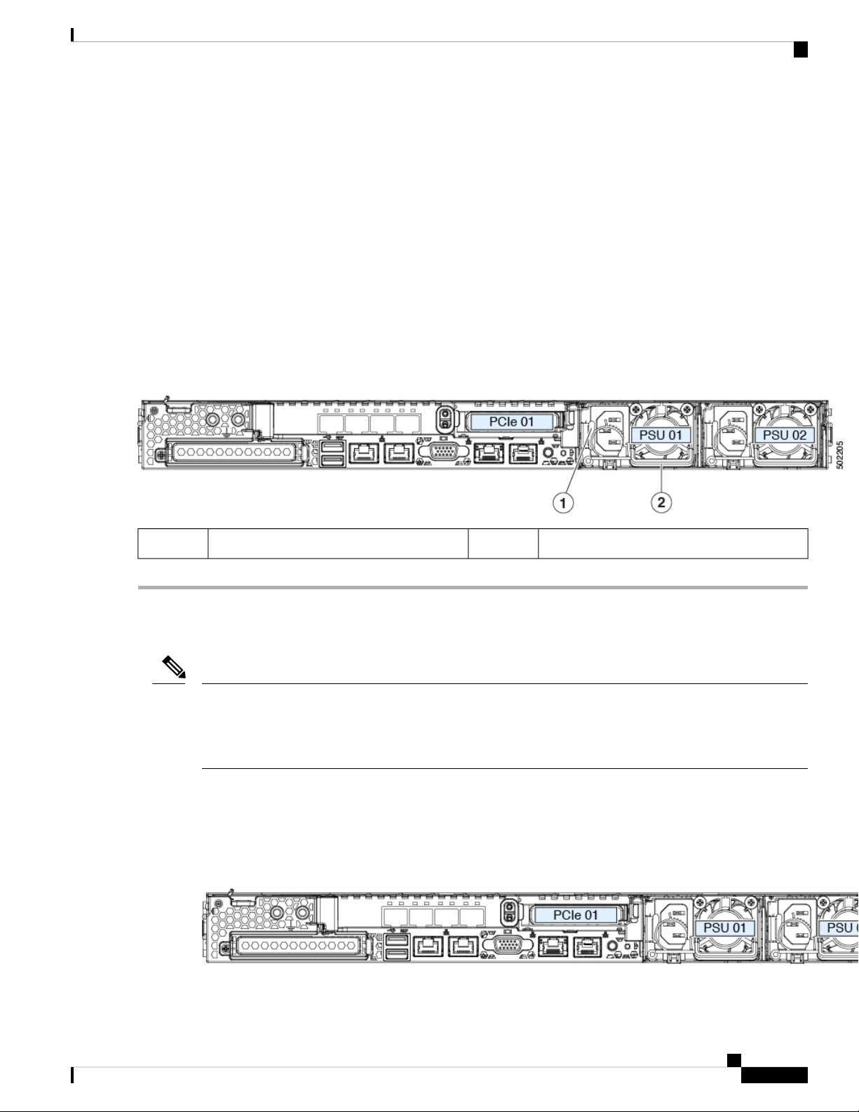
Maintaining the Server
• If your server has only one power supply, shut down and remove power from the server as described in Shutting
Down and Removing Power From the Server, on page 29.
• If your server has two power supplies, you do not have to shut down the server.
b) Remove the power cord from the power supply that you are replacing.
c) Grasp the power supply handle while pinching the release lever toward the handle.
d) Pull the power supply out of the bay.
Step 2 Install a new power supply:
a) Grasp the power supply handle and insert the new power supply into the empty bay.
b) Push the power supply into the bay until the release lever locks.
c) Connect the power cord to the new power supply.
d) Only if you shut down the server, press the Power button to boot the server to main power mode.
Figure 33: Replacing AC Power Supplies
Replacing a PCIe Card
Replacing a PCIe Card
Note
PCIe Slot Specifications
Cisco supports all PCIe cards qualified and sold by Cisco. PCIe cards not qualified or sold by Cisco are the
responsibility of the customer. Although Cisco will always stand behind and support the C-Series rack-mount
servers, customers using standard, off-the-shelf, third-party cards must go to the third-party card vendor for
support if any issue with that particular card occurs.
The server contains two PCIe slots on one riser assembly for horizontal installation of PCIe cards. Both slots
support the NCSI protocol and 12V standby power.
Figure 34: Rear Panel, Showing PCIe Slot Numbering
Power supply handle2Power supply release lever1
Cisco APIC M3/L3 Server Installation and Service Guide
67
Page 76

Replacing a PCIe Card
Table 6: PCIe Riser 1/Slot 1
Maintaining the Server
The following tables describe the specifications for the slots.
Slot Number
slot
Table 7: PCIe Riser 2/Slot 2
Slot Number
for front-panel NVMe
SSDs
Note
Electrical Lane
Width
Connector
Length
Maximum Card
Length
One socket for Micro SD cardMicro SD card
Maximum Card
Length
Width
Gen-3 x8PCIe cable connector
Connector LengthElectrical Lane
Other end of cable connects to front drive backplane to support front-panel NVMe
SSDs.
Riser 1/Slot 1 is not available in single-CPU configurations.
Card Height (Rear Panel
Opening)
Panel Opening)
NCSI
Support
YesFull-height¾ lengthx24 connectorGen-3 x161
NCSI SupportCard Height (Rear
Yes½ height½ lengthx24 connectorGen-3 x161
Replacing a PCIe Card
Note
If you are installing a Cisco Virtual Interface Card, there are prerequisite considerations. See Cisco Virtual
Interface Card (VIC) Considerations, on page 70.
Note
RAID controller cards install into a separate mRAID riser. See Replacing a SAS Storage Controller Card
(RAID or HBA), on page 74.
Step 1 Remove an existing PCIe card (or a blank filler panel) from the PCIe riser:
a) Shut down and remove power from the server as described in Shutting Down and Removing Power From the Server,
on page 29.
b) Slide the server out the front of the rack far enough so that you can remove the top cover. You might have to detach
cables from the rear panel to provide clearance.
Caution
c) Remove the top cover from the server as described in Removing the Server Top Cover, on page 30.
d) Remove any cables from the ports of the PCIe card that you are replacing.
If you cannot safely view and access the component, remove the server from the rack.
Cisco APIC M3/L3 Server Installation and Service Guide
68
Page 77

Maintaining the Server
e) Use two hands to grasp the external riser handle and the blue area at the front of the riser.
f) Lift straight up to disengage the riser's connectors from the two sockets on the motherboard. Set the riser upside-down
on an antistatic surface.
g) Open the hinged plastic retainer that secures the rear-panel tab of the card.
h) Pull evenly on both ends of the PCIe card to remove it from the socket on the PCIe riser.
If the riser has no card, remove the blanking panel from the rear opening of the riser.
Step 2 Install a new PCIe card:
a) With the hinged tab retainer open, align the new PCIe card with the empty socket on the PCIe riser.
PCIe riser 1/slot 1 has a long-card guide at the front end of the riser. Use the slot in the long-card guide to help support
a full-length card.
b) Push down evenly on both ends of the card until it is fully seated in the socket.
c) Ensure that the card’s rear panel tab sits flat against the riser rear-panel opening and then close the hinged tab retainer
over the card’s rear-panel tab.
Figure 35: PCIe Riser Assembly
Replacing a PCIe Card
Hinged card retainer (one each slot)4PCIe slot 1 rear-panel opening1
5External riser handle2
PCIe connector for cable that supports
front-panel NVMe SSDs
Cisco APIC M3/L3 Server Installation and Service Guide
69
Page 78

Cisco Virtual Interface Card (VIC) Considerations
PCIe slot 2 rear-panel opening3
d) Position the PCIe riser over its two sockets on the motherboard and over the two chassis alignment channels.
Figure 36: PCIe Riser Alignment Features
Maintaining the Server
e) Carefully push down on both ends of the PCIe riser to fully engage its two connectors with the two sockets on the
motherboard.
f) Replace the top cover to the server.
g) Replace the server in the rack, replace cables, and then fully power on the server by pressing the Power button.
Cisco Virtual Interface Card (VIC) Considerations
This section describes VIC card support and special considerations for this server.
Note
If you use the Cisco Card NIC mode, you must also make a VIC Slot setting that matches where your VIC is
installed. The options are Riser1, Riser2, and Flex-LOM. See NIC Mode and NIC Redundancy Settings, on
page 19 for more information about NIC modes.
Table 8: VIC Support and Considerations in This Server
VIC
How Many
Supported in
Server
Slots That
Support VICs
Riser alignment features in chassis2Blue riser handle1
Primary Slot For
Cisco UCS Manager
Integration
Primary Slot For
Cisco Card NIC
Mode
Minimum Cisco
IMC Firmware
Cisco APIC M3/L3 Server Installation and Service Guide
70
Page 79

Maintaining the Server
Replacing an mLOM Card
2 PCIeCisco VIC 1455
APIC-PCIE-C25Q-04
Note
This VIC supports 10/25-Gigabit with the following restrictions:
• All ports must have the same speed.
• Port-0 and port-1 is one pair, corresponding to eth2-1 on APIC. Port-2 and port-3 is another pair,
corresponding to eth2-2 on APIC. Only one connection is allowed for each pair (For example, you can
connect one cable to either port-0 or port-1, and you can connect another one cable to either port-2 or
port-3. Do not connect two cables on any pair.)
Replacing an mLOM Card
The server supports a modular LOM (mLOM) card to provide additional rear-panel connectivity. The horizontal
mLOM socket is on the motherboard, under the mRAID riser.
The mLOM socket provides a Gen-3 x16 PCIe lane. The socket remains powered when the server is in 12 V
standby power mode and it supports the network communications services interface (NCSI) protocol.
4.0(1)PCIe 1PCIe 1PCIe 1
PCIe 2
Step 1 Remove any existing mLOM card (or a blanking panel):
a) Shut down and remove power from the server as described in Shutting Down and Removing Power From the Server,
on page 29.
b) Slide the server out the front of the rack far enough so that you can remove the top cover. You might have to detach
cables from the rear panel to provide clearance.
Caution
If you cannot safely view and access the component, remove the server from the rack.
c) Remove the top cover from the server as described in Removing the Server Top Cover, on page 30.
d) Remove the mRAID riser to provide access to the mLOM socket below the riser.
To remove the mRAID riser, use both hands to grasp the external blue handle on the rear and the blue finger-grip on
the front. Lift straight up.
You do not have to disconnect cables from any RAID card or interposer card that is installed in the riser. Carefully
move the riser aside only far enough to provide clearance.
e) Loosen the single captive thumbscrew that secures the mLOM card to the threaded standoff on the chassis floor.
f) Slide the mLOM card horizontally to free it from the socket, then lift it out of the server.
Step 2 Install a new mLOM card:
a) Set the mLOM card on the chassis floor so that its connector is aligned with the motherboard socket.
b) Push the card horizontally to fully engage the card's edge connector with the socket.
c) Tighten the captive thumbscrew to secure the card to the standoff on the chassis floor.
d) Return the mRAID riser to its socket.
Cisco APIC M3/L3 Server Installation and Service Guide
71
Page 80

Replacing an mRAID Riser (Riser 3)
Carefully align the riser's edge connector with the motherboard socket at the same time you align the two channels
on the riser with the two pegs on the inner chassis wall. Press down evenly on both ends of the riser to fully engage
its connector with the motherboard socket.
e) Replace the top cover to the server.
f) Replace the server in the rack, replace cables, and then fully power on the server by pressing the Power button.
Figure 37: Location of the mLOM Card Socket Below the mRAID Riser
Maintaining the Server
Replacing an mRAID Riser (Riser 3)
The server has a dedicated internal riser that is used for either a Cisco modular storage controller card (RAID
or HBA) or the SATA interposer card for embedded software RAID. This riser plugs into a dedicated
motherboard socket and provides a horizontal socket for the installed card.
This riser can be ordered as the following options:
• UCSC-XRAIDR-220M5—Replacement unit for this mRAID riser.
• UCSC-MRAID1GB-KIT—Kit for first-time addition of this riser (includes RAID controller, supercap,
and supercap cable).
See also Replacing a SAS Storage Controller Card (RAID or HBA), on page 74.
See also Replacing the Supercap (RAID Backup), on page 76.
• UCSC-SATA-KIT-M5—Kit for first-time addition of this riser (includes SATA interposer for embedded
software RAID and SATA cables).
Position of mLOM card thumbscrew2Position of horizontal mLOM card socket1
Cisco APIC M3/L3 Server Installation and Service Guide
72
Page 81

Maintaining the Server
See also Replacing a SATA Interposer Card , on page 78.
Step 1 Prepare the server for component installation:
a) Shut down and remove power from the server as described in Shutting Down and Removing Power From the Server,
on page 29.
b) Slide the server out the front of the rack far enough so that you can remove the top cover. You might have to detach
cables from the rear panel to provide clearance.
Replacing an mRAID Riser (Riser 3)
Caution
If you cannot safely view and access the component, remove the server from the rack.
c) Remove the top cover from the server as described in Removing the Server Top Cover, on page 30.
Step 2 Remove the existing mRAID riser:
a) Using both hands, grasp the external blue handle on the rear of the riser and the blue finger-grip on the front end of
the riser.
b) Lift the riser straight up to disengage it from the motherboard socket.
c) Set the riser upside down on an antistatic surface.
d) Remove any card from the riser. Open the blue card-ejector lever that is on the edge of the card and then pull the card
straight out from its socket on the riser.
Step 3 Install a new mRAID riser:
a) Install your card into the new riser. Close the card-ejector lever on the card to lock it into the riser.
b) Connect cables to the installed card.
See Storage Controller and Backplane Connectors, on page 102 for cabling instructions for controller cards and
interposer cards.
c) Align the riser with the socket on the motherboard. At the same time, align the two slots on the back side of the
bracket with the two pegs on the inner chassis wall.
d) Push down gently to engage the riser with the motherboard socket. The metal riser bracket must also engage the two
pegs that secure it to the chassis wall.
Step 4 Replace the top cover to the server.
Step 5 Replace the server in the rack, replace cables, and then fully power on the server by pressing the Power button.
Cisco APIC M3/L3 Server Installation and Service Guide
73
Page 82

Replacing a SAS Storage Controller Card (RAID or HBA)
Figure 38: mRAID Riser (Internal Riser 3) Location
Maintaining the Server
Card-ejector lever3External blue handle1
-Two pegs on inner chassis wall2
Replacing a SAS Storage Controller Card (RAID or HBA)
For hardware-based storage control, the server can use a Cisco modular SAS RAID controller or SAS HBA
that plugs into a horizontal socket on a dedicated mRAID riser (internal riser 3).
Note
You cannot use a hardware RAID controller card and the embedded software RAID controller to control
front-panel drives at the same time.
Storage Controller Card Firmware Compatibility
Firmware on the storage controller (RAID or HBA) must be verified for compatibility with the current Cisco
IMC and BIOS versions that are installed on the server. If not compatible, upgrade or downgrade the storage
controller firmware using the Host Upgrade Utility (HUU) for your firmware release to bring it to a compatible
level.
See the HUU guide for your Cisco IMC release for instructions on downloading and using the utility to bring
server components to compatible levels: HUU Guides.
Cisco APIC M3/L3 Server Installation and Service Guide
74
Page 83

Maintaining the Server
Replacing a SAS Storage Controller Card (RAID or HBA)
Note
For servers running in standalone mode only: After you replace controller hardware (APIC-RAID-M5),
you must run the Cisco Host Upgrade Utility (HUU) to update the controller firmware, even if the firmware
Current Version is the same as the Update Version. This is necessary to program the controller's suboem-id
to the correct value for the server SKU. If you do not do this, drive enumeration might not display correctly
in the software. This issue does not affect servers controlled in UCSM mode.
Replacing a SAS Storage Controller Card (RAID or HBA)
Step 1 Prepare the server for component installation:
a) Shut down and remove power from the server.
b) Slide the server out the front of the rack far enough so that you can remove the top cover. You might have to detach
cables from the rear panel to provide clearance.
Caution
c) Remove the top cover from the server as described in Removing the Server Top Cover, on page 30.
Step 2 Remove the mRAID riser (riser 3) from the server:
a) Using both hands, grasp the external blue handle on the rear of the riser and the blue finger-grip on the front end of
the riser.
b) Lift the riser straight up to disengage it from the motherboard socket.
c) Set the riser upside down on an antistatic surface.
Step 3 Remove any existing card from the riser:
a) Disconnect cables from the existing card.
b) Open the blue card-ejector lever on the back side of the card to eject it from the socket on the riser.
c) Pull the card from the riser and set it aside.
If you cannot safely view and access the component, remove the server from the rack.
Step 4 Install a new storage controller card to the riser:
a) With the riser upside down, set the card on the riser.
b) Push on both corners of the card to seat its connector in the riser socket.
c) Close the card-ejector lever on the card to lock it into the riser.
d) Connect cables to the installed card.
See Storage Controller and Backplane Connectors, on page 102 for cabling instructions for controller cards and
interposer cards.
Step 5 Return the riser to the server:
a) Align the connector on the riser with the socket on the motherboard. At the same time, align the two slots on the back
side of the bracket with the two pegs on the inner chassis wall.
b) Push down gently to engage the riser connector with the motherboard socket. The metal riser bracket must also engage
the two pegs that secure it to the chassis wall.
Step 6 Replace the top cover to the server.
Step 7 Replace the server in the rack, replace cables, and then fully power on the server by pressing the Power button.
Step 8 If your server is running in standalone mode, use the Cisco Host Upgrade Utility to update the controller firmware and
program the correct suboem-id for the controller.
Cisco APIC M3/L3 Server Installation and Service Guide
75
Page 84

Replacing the Supercap (RAID Backup)
Maintaining the Server
Note
For servers running in standalone mode only: After you replace controller hardware (APIC-RAID-M5),
you must run the Cisco Host Upgrade Utility (HUU) to update the controller firmware, even if the firmware
Current Version is the same as the Update Version. This is necessary to program the controller's suboem-id to
the correct value for the server SKU. If you do not do this, drive enumeration might not display correctly in
the software. This issue does not affect servers controlled in UCSM mode.
See the HUU guide for your Cisco IMC release for instructions on downloading and using the utility to bring
server components to compatible levels: HUU Guides.
Figure 39: mRAID Riser (Internal Riser 3) Location
Replacing the Supercap (RAID Backup)
This server supports installation of one supercap unit. The unit mounts to a bracket that is in the middle of
the row of cooling fan modules.
The supercap provides approximately three years of backup for the disk write-back cache DRAM in the case
of a sudden power loss by offloading the cache to the NAND flash.
Cisco APIC M3/L3 Server Installation and Service Guide
76
Card-ejector lever3External blue handle1
-Two pegs on inner chassis wall2
Page 85

Maintaining the Server
Replacing the Supercap (RAID Backup)
Warning
There is danger of explosion if the battery is replaced incorrectly. Replace the battery only with the
same or equivalent type recommended by the manufacturer. Dispose of used batteries according to the
manufacturer’s instructions.
Statement 1015
Step 1 Prepare the server for component installation:
a) Shut down and remove power from the server as described in Shutting Down and Removing Power From the Server,
on page 29.
b) Slide the server out the front of the rack far enough so that you can remove the top cover. You might have to detach
cables from the rear panel to provide clearance.
Caution
If you cannot safely view and access the component, remove the server from the rack.
c) Remove the top cover from the server as described in Removing the Server Top Cover, on page 30.
Step 2 Remove an existing supercap:
a) Disconnect the supercap cable from the existing supercap.
b) Push aside the securing tab to open the hinged latch that secures the supercap to its bracket on the removable air
baffle.
c) Lift the supercap free of the bracket and set it aside.
Step 3 Install a new supercap:
a) Set the new supercap into the mounting bracket.
b) Close the hinged plastic clip over the supercap. Push down until the securing tab clicks.
c) Connect the supercap cable from the RAID controller card to the connector on the new supercap cable.
Step 4 Replace the top cover to the server.
Step 5 Replace the server in the rack, replace cables, and then fully power on the server by pressing the Power button.
Cisco APIC M3/L3 Server Installation and Service Guide
77
Page 86

Replacing a SATA Interposer Card
Figure 40: Replacing Supercap
Maintaining the Server
Replacing a SATA Interposer Card
For software-based storage control that uses the server's embedded SATA controller, the server requires a
SATA interposer card that plugs into a horizontal socket on a dedicated mRAID riser (internal riser 3).
Note
You cannot use a hardware RAID controller card and the embedded software RAID controller at the same
time.
Step 1 Prepare the server for component installation:
Cisco APIC M3/L3 Server Installation and Service Guide
78
Hinged latch2Securing tab1
Page 87

Maintaining the Server
a) Shut down and remove power from the server as described in Shutting Down and Removing Power From the Server,
on page 29.
b) Slide the server out the front of the rack far enough so that you can remove the top cover. You might have to detach
cables from the rear panel to provide clearance.
Replacing a SATA Interposer Card
Caution
If you cannot safely view and access the component, remove the server from the rack.
c) Remove the top cover from the server as described in Removing the Server Top Cover, on page 30.
Step 2 Remove the mRAID riser (riser 3) from the server:
a) Using both hands, grasp the external blue handle on the rear of the riser and the blue finger-grip on the front end of
the riser.
b) Lift the riser straight up to disengage it from the motherboard socket.
c) Set the riser upside down on an antistatic surface.
Step 3 Remove any existing card from the riser:
a) Disconnect cables from the existing card.
b) Open the blue card-ejector lever on the back side of the card to eject it from the socket on the riser.
c) Pull the card from the riser and set it aside.
Step 4 Install a new card to the riser:
a) With the riser upside down, set the card on the riser.
b) Push on both corners of the card to seat its connector in the riser socket.
c) Close the card-ejector lever on the card to lock it into the riser.
Step 5 Return the riser to the server:
a) Align the connector on the riser with the socket on the motherboard. At the same time, align the two slots on the back
side of the bracket with the two pegs on the inner chassis wall.
b) Push down gently to engage the riser connector with the motherboard socket. The metal riser bracket must also engage
the two pegs that secure it to the chassis wall.
Step 6 Reconnect the cables to their connectors on the new card.
Step 7 Replace the top cover to the server.
Step 8 Replace the server in the rack, replace cables, and then fully power on the server by pressing the Power button.
Cisco APIC M3/L3 Server Installation and Service Guide
79
Page 88

Replacing a Chassis Intrusion Switch
Figure 41: mRAID Riser (Internal Riser 3) Location
Maintaining the Server
Replacing a Chassis Intrusion Switch
The chassis intrusion switch in an optional security feature that logs an event in the system event log (SEL)
whenever the cover is removed from the chassis.
Step 1 Prepare the server for component installation:
a) Shut down and remove power from the server as described in Shutting Down and Removing Power From the Server,
on page 29.
b) Slide the server out the front of the rack far enough so that you can remove the top cover. You might have to detach
cables from the rear panel to provide clearance.
Caution
c) Remove the top cover from the server as described in Removing the Server Top Cover, on page 30.
Step 2 Remove an existing intrusion switch:
a) Disconnect the intrusion switch cable from the socket on the motherboard.
b) Use a #1 Phillips-head screwdriver to loosen and remove the single screw that holds the switch mechanism to the
chassis wall.
c) Slide the switch mechanism straight up to disengage it from the clips on the chassis.
If you cannot safely view and access the component, remove the server from the rack.
Card-ejector lever3External blue handle1
-Two pegs on inner chassis wall2
Cisco APIC M3/L3 Server Installation and Service Guide
80
Page 89
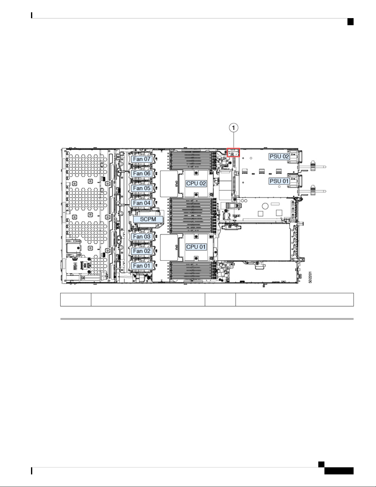
Maintaining the Server
Installing a Trusted Platform Module (TPM)
Step 3 Install a new intrusion switch:
a) Slide the switch mechanism down into the clips on the chassis wall so that the screwhole lines up.
b) Use a #1 Phillips-head screwdriver to install the single screw that secures the switch mechanism to the chassis wall.
c) Connect the switch cable to the socket on the motherboard.
Step 4 Replace the cover to the server.
Step 5 Replace the server in the rack, replace cables, and then fully power on the server by pressing the Power button.
Figure 42: Replacing a Chassis Intrusion Switch
-Intrusion switch location1
Installing a Trusted Platform Module (TPM)
The trusted platform module (TPM) is a small circuit board that plugs into a motherboard socket and is then
permanently secured with a one-way screw. The socket location is on the motherboard below PCIe riser 2.
TPM Considerations
• This server supports either TPM version 1.2 or TPM version 2.0.
• Field replacement of a TPM is not supported; you can install a TPM after-factory only if the server does
not already have a TPM installed.
• If there is an existing TPM 1.2 installed in the server, you cannot upgrade to TPM 2.0. If there is no
existing TPM in the server, you can install TPM 2.0.
Cisco APIC M3/L3 Server Installation and Service Guide
81
Page 90

Installing and Enabling a TPM
• If the TPM 2.0 becomes unresponsive, reboot the server.
Installing and Enabling a TPM
Note
Field replacement of a TPM is not supported; you can install a TPM after-factory only if the server does not
already have a TPM installed.
This topic contains the following procedures, which must be followed in this order when installing and enabling
a TPM:
1. Installing the TPM Hardware
2. Enabling the TPM in the BIOS
3. Enabling the Intel TXT Feature in the BIOS
Installing TPM Hardware
Maintaining the Server
Note
For security purposes, the TPM is installed with a one-way screw. It cannot be removed with a standard
screwdriver.
Step 1 Prepare the server for component installation:
a) Shut down and remove power from the server as described in Shutting Down and Removing Power From the Server,
on page 29.
b) Slide the server out the front of the rack far enough so that you can remove the top cover. You might have to detach
cables from the rear panel to provide clearance.
Caution
If you cannot safely view and access the component, remove the server from the rack.
c) Remove the top cover from the server as described in Removing the Server Top Cover, on page 30.
Step 2 Check if there is a card installed in PCIe riser 2:
• If no card is installed in PCIe riser 2, you can access the TPM socket. Go to the next step.
• If a card is installed in PCIe riser 2, remove the PCIe riser assembly from the chassis to provide clearance before
continuing with the next step. See Replacing a PCIe Card, on page 68 for instructions on removing the PCIe riser.
Step 3 Install a TPM:
a) Locate the TPM socket on the motherboard, as shown below.
b) Align the connector that is on the bottom of the TPM circuit board with the motherboard TPM socket. Align the
screw hole on the TPM board with the screw hole that is adjacent to the TPM socket.
c) Push down evenly on the TPM to seat it in the motherboard socket.
d) Install the single one-way screw that secures the TPM to the motherboard.
e) If you removed the PCIe riser assembly to provide clearance, return it to the server now.
Step 4 Replace the cover to the server.
Cisco APIC M3/L3 Server Installation and Service Guide
82
Page 91

Maintaining the Server
Enabling the TPM in the BIOS
Step 5 Replace the server in the rack, replace cables, and then fully power on the server by pressing the Power button.
Figure 43: Location of the TPM Socket
1
any card in PCIe riser 2
Step 6 Continue with Enabling the TPM in the BIOS, on page 83.
Enabling the TPM in the BIOS
After hardware installation, you must enable TPM support in the BIOS.
Note
You must set a BIOS Administrator password before performing this procedure. To set this password, press
the F2 key when prompted during system boot to enter the BIOS Setup utility. Then navigate to Security >
Set Administrator Password and enter the new password twice as prompted.
Step 1 Enable TPM Support:
a) Watch during bootup for the F2 prompt, and then press F2 to enter BIOS setup.
b) Log in to the BIOS Setup Utility with your BIOS Administrator password.
c) On the BIOS Setup Utility window, choose the Advanced tab.
d) Choose Trusted Computing to open the TPM Security Device Configuration window.
e) Change TPM SUPPORT to Enabled.
f) Press F10 to save your settings and reboot the server.
-TPM socket location on motherboard below
Step 2 Verify that TPM support is now enabled:
a) Watch during bootup for the F2 prompt, and then press F2 to enter BIOS setup.
Cisco APIC M3/L3 Server Installation and Service Guide
83
Page 92

Enabling the Intel TXT Feature in the BIOS
b) Log into the BIOS Setup utility with your BIOS Administrator password.
c) Choose the Advanced tab.
d) Choose Trusted Computing to open the TPM Security Device Configuration window.
e) Verify that TPM SUPPORT and TPM State are Enabled.
Step 3 Continue with Enabling the Intel TXT Feature in the BIOS, on page 84.
Enabling the Intel TXT Feature in the BIOS
Intel Trusted Execution Technology (TXT) provides greater protection for information that is used and stored
on the business server. A key aspect of that protection is the provision of an isolated execution environment
and associated sections of memory where operations can be conducted on sensitive data, invisibly to the rest
of the system. Intel TXT provides for a sealed portion of storage where sensitive data such as encryption keys
can be kept, helping to shield them from being compromised during an attack by malicious code.
Step 1 Reboot the server and watch for the prompt to press F2.
Step 2 When prompted, press F2 to enter the BIOS Setup utility.
Step 3 Verify that the prerequisite BIOS values are enabled:
a) Choose the Advanced tab.
b) Choose Intel TXT(LT-SX) Configuration to open the Intel TXT(LT-SX) Hardware Support window.
c) Verify that the following items are listed as Enabled:
Maintaining the Server
• VT-d Support (default is Enabled)
• VT Support (default is Enabled)
• TPM Support
• TPM State
d) Do one of the following:
• If VT-d Support and VT Support are already enabled, skip to step 4.
• If VT-d Support and VT Support are not enabled, continue with the next steps to enable them.
e) Press Escape to return to the BIOS Setup utility Advanced tab.
f) On the Advanced tab, choose Processor Configuration to open the Processor Configuration window.
g) Set Intel (R) VT and Intel (R) VT-d to Enabled.
Step 4 Enable the Intel Trusted Execution Technology (TXT) feature:
a) Return to the Intel TXT(LT-SX) Hardware Support window if you are not already there.
b) Set TXT Support to Enabled.
Step 5 Press F10 to save your changes and exit the BIOS Setup utility.
Cisco APIC M3/L3 Server Installation and Service Guide
84
Page 93

Maintaining the Server
Service Headers and Jumpers
This server includes two blocks of headers (J38, J39) that you can jumper for certain service and debug
functions.
Figure 44: Location of Service Header Blocks J38 and J39
Service Headers and Jumpers
Location of header block J396Location of header block J381
J39 pin 1 arrow printed on motherboard7J38 pin 1 arrow printed on motherboard2
8Clear CMOS: J38 pins 9 - 103
9Recover BIOS: J38 pins 11 - 124
Cisco APIC M3/L3 Server Installation and Service Guide
Boot Cisco IMC from alternate image: J39 pins 1 2
Reset Cisco IMC password to default: J39 pins 3 4
Reset Cisco IMC to defaults: J39 pins 5 - 610Clear password: J38 pins 13 - 145
85
Page 94

Using the Clear CMOS Header (J38, Pins 9 - 10)
Using the Clear CMOS Header (J38, Pins 9 - 10)
You can use this header to clear the server’s CMOS settings in the case of a system hang. For example, if the
server hangs because of incorrect settings and does not boot, use this jumper to invalidate the settings and
reboot with defaults.
Maintaining the Server
Caution
Step 1 Shut down and remove power from the server as described in Shutting Down and Removing Power From the Server,
on page 29. Disconnect power cords from all power supplies.
Step 2 Slide the server out the front of the rack far enough so that you can remove the top cover. You might have to detach
cables from the rear panel to provide clearance.
Caution
Step 3 Remove the top cover from the server as described in Removing the Server Top Cover, on page 30.
Step 4 Locate header block J38 and pins 9-10, as shown in Service Headers and Jumpers, on page 85.
Step 5 Install a two-pin jumper across pins 9 and 10.
Step 6 Reinstall the top cover and reconnect AC power cords to the server. The server powers up to standby power mode,
indicated when the Power LED on the front panel is amber.
Step 7 Return the server to main power mode by pressing the Power button on the front panel. The server is in main power
mode when the Power LED is green.
Note
Step 8 Press the Power button to shut down the server to standby power mode, and then remove AC power cords from the
server to remove all power.
Step 9 Remove the top cover from the server.
Step 10 Remove the jumper that you installed.
Clearing the CMOS removes any customized settings and might result in data loss. Make a note of any
necessary customized settings in the BIOS before you use this clear CMOS procedure.
If you cannot safely view and access the component, remove the server from the rack.
You must allow the entire server to reboot to main power mode to complete the reset. The state of the jumper
cannot be determined without the host CPU running.
Note
Step 11 Replace the top cover, replace the server in the rack, replace power cords and any other cables, and then power on the
server by pressing the Power button.
If you do not remove the jumper, the CMOS settings are reset to the defaults every time you power-cycle the
server.
Using the BIOS Recovery Header (J38, Pins 11 - 12)
Depending on which stage the BIOS becomes corrupted, you might see different behavior.
• If the BIOS BootBlock is corrupted, you might see the system get stuck on the following message:
Initializing and configuring memory/hardware
• If it is a non-BootBlock corruption, a message similar to the following is displayed:
Cisco APIC M3/L3 Server Installation and Service Guide
86
Page 95

Maintaining the Server
Procedure 1: Reboot With recovery.cap File
****BIOS FLASH IMAGE CORRUPTED****
Flash a valid BIOS capsule file using Cisco IMC WebGUI or CLI interface.
IF Cisco IMC INTERFACE IS NOT AVAILABLE, FOLLOW THE STEPS MENTIONED BELOW.
1. Connect the USB stick with bios.cap file in root folder.
2. Reset the host.
IF THESE STEPS DO NOT RECOVER THE BIOS
1. Power off the system.
2. Mount recovery jumper.
3. Connect the USB stick with bios.cap file in root folder.
4. Power on the system.
Wait for a few seconds if already plugged in the USB stick.
REFER TO SYSTEM MANUAL FOR ANY ISSUES.
Note
As indicated by the message shown above, there are two procedures for recovering the BIOS. Try procedure
1 first. If that procedure does not recover the BIOS, use procedure 2.
Procedure 1: Reboot With recovery.cap File
Step 1 Download the BIOS update package and extract it to a temporary location.
Step 2 Copy the contents of the extracted recovery folder to the root directory of a USB drive. The recovery folder contains the
bios.cap file that is required in this procedure.
Note
Step 3 Insert the USB drive into a USB port on the server.
Step 4 Reboot the server.
Step 5 Return the server to main power mode by pressing the Power button on the front panel.
The server boots with the updated BIOS boot block. When the BIOS detects a valid bios.cap file on the USB drive, it
displays this message:
Found a valid recovery file...Transferring to Cisco IMC
System would flash the BIOS image now...
System would restart with recovered image after a few seconds...
Step 6 Wait for server to complete the BIOS update, and then remove the USB drive from the server.
The bios.cap file must be in the root directory of the USB drive. Do not rename this file. The USB drive must
be formatted with either the FAT16 or FAT32 file system.
Note
During the BIOS update, Cisco IMC shuts down the server and the screen goes blank for about 10 minutes.
Do not unplug the power cords during this update. Cisco IMC powers on the server after the update is complete.
Procedure 2: Use BIOS Recovery Header and bios.cap Recovery File
Step 1 Download the BIOS update package and extract it to a temporary location.
Step 2 Copy the contents of the extracted recovery folder to the root directory of a USB drive. The recovery folder contains
the bios.cap file that is required in this procedure.
Note
The bios.cap file must be in the root directory of the USB drive. Do not rename this file. The USB drive must
be formatted with either the FAT16 or FAT32 file system.
Cisco APIC M3/L3 Server Installation and Service Guide
87
Page 96

Maintaining the Server
Using the Clear Password Header (J38, Pins 13 - 14)
Step 3 Shut down and remove power from the server as described in Shutting Down and Removing Power From the Server,
on page 29. Disconnect power cords from all power supplies.
Step 4 Slide the server out the front of the rack far enough so that you can remove the top cover. You might have to detach
cables from the rear panel to provide clearance.
Caution
If you cannot safely view and access the component, remove the server from the rack.
Step 5 Remove the top cover from the server as described in Removing the Server Top Cover, on page 30.
Step 6 Locate header block J38 and pins 11-12, as shown in Service Headers and Jumpers, on page 85.
Step 7 Install a two-pin jumper across pins 11 and 12.
Step 8 Reconnect AC power cords to the server. The server powers up to standby power mode.
Step 9 Insert the USB thumb drive that you prepared in Step 2 into a USB port on the server.
Step 10 Return the server to main power mode by pressing the Power button on the front panel.
The server boots with the updated BIOS boot block. When the BIOS detects a valid bios.cap file on the USB drive, it
displays this message:
Found a valid recovery file...Transferring to Cisco IMC
System would flash the BIOS image now...
System would restart with recovered image after a few seconds...
Step 11 Wait for server to complete the BIOS update, and then remove the USB drive from the server.
Note
During the BIOS update, Cisco IMC shuts down the server and the screen goes blank for about 10 minutes.
Do not unplug the power cords during this update. Cisco IMC powers on the server after the update is complete.
Step 12 After the server has fully booted, power off the server again and disconnect all power cords.
Step 13 Remove the jumper that you installed.
Note
If you do not remove the jumper, after recovery completion you see the prompt, “Please remove the recovery
jumper.”
Step 14 Replace the top cover, replace the server in the rack, replace power cords and any other cables, and then power on the
server by pressing the Power button.
Using the Clear Password Header (J38, Pins 13 - 14)
You can use this switch to clear the administrator password.
Step 1 Shut down and remove power from the server as described in Shutting Down and Removing Power From the Server,
on page 29. Disconnect power dords from all power supplies.
Step 2 Slide the server out the front of the rack far enough so that you can remove the top cover. You might have to detach
cables from the rear panel to provide clearance.
Caution
Step 3 Remove the top cover from the server as described in Removing the Server Top Cover, on page 30.
Step 4 Install a two-pin jumper across J38 pins 13 and 14.
Step 5 Reinstall the top cover and reconnect AC power cords to the server. The server powers up to standby power mode,
indicated when the Power LED on the front panel is amber.
If you cannot safely view and access the component, remove the server from the rack.
Cisco APIC M3/L3 Server Installation and Service Guide
88
Page 97

Maintaining the Server
Using the Boot Alternate Cisco IMC Image Header (J39, Pins 1 - 2)
Step 6 Return the server to main power mode by pressing the Power button on the front panel. The server is in main power
mode when the Power LED is green.
Note
You must allow the entire server to reboot to main power mode to complete the reset. The state of the jumper
cannot be determined without the host CPU running.
Step 7 Press the Power button to shut down the server to standby power mode, and then remove AC power cords from the
server to remove all power.
Step 8 Remove the top cover from the server.
Step 9 Remove the jumper that you installed.
Note
If you do not remove the jumper, the password is cleared every time you power-cycle the server.
Step 10 Replace the top cover, replace the server in the rack, replace power cords and any other cables, and then power on the
server by pressing the Power button.
Using the Boot Alternate Cisco IMC Image Header (J39, Pins 1 - 2)
You can use this Cisco IMC debug header to force the system to boot from an alternate Cisco IMC image.
Step 1 Shut down and remove power from the server as described in Shutting Down and Removing Power From the Server.
Disconnect power cords from all power supplies.
Step 2 Slide the server out the front of the rack far enough so that you can remove the top cover. You might have to detach
cables from the rear panel to provide clearance.
Caution
If you cannot safely view and access the component, remove the server from the rack.
Step 3 Remove the top cover from the server as described in Removing the Server Top Cover.
Step 4 Locate header block J39, pins 1-2, as shown in Service Headers and Jumpers.
Step 5 Install a two-pin jumper across J39 pins 1 and 2.
Step 6 Reinstall the top cover and reconnect AC power cords to the server. The server powers up to standby power mode,
indicated when the Power LED on the front panel is amber.
Step 7 Return the server to main power mode by pressing the Power button on the front panel. The server is in main power
mode when the Power LED is green.
Note
When you next log in to Cisco IMC, you see a message similar to the following:
'Boot from alternate image' debug functionality is enabled.
CIMC will boot from alternate image on next reboot or input power cycle.
Step 8 Press the Power button to shut down the server to standby power mode, and then remove AC power cords from the
server to remove all power.
Step 9 Remove the top cover from the server.
Step 10 Remove the jumper that you installed.
Note
If you do not remove the jumper, the server will boot from an alternate Cisco IMC image every time that you
power cycle the server or reboot Cisco IMC.
Cisco APIC M3/L3 Server Installation and Service Guide
89
Page 98

Maintaining the Server
Using the Reset Cisco IMC Password to Default Header (J39, Pins 3 - 4)
Step 11 Replace the top cover, replace the server in the rack, replace power cords and any other cables, and then power on the
server by pressing the Power button.
Using the Reset Cisco IMC Password to Default Header (J39, Pins 3 - 4)
You can use this Cisco IMC debug header to force the Cisco IMC password back to the default.
Step 1 Shut down and remove power from the server as described in Shutting Down and Removing Power From the Server,
on page 29. Disconnect power cords from all power supplies.
Step 2 Slide the server out the front of the rack far enough so that you can remove the top cover. You might have to detach
cables from the rear panel to provide clearance.
Caution
If you cannot safely view and access the component, remove the server from the rack.
Step 3 Remove the top cover from the server as described in Removing the Server Top Cover, on page 30.
Step 4 Locate header block J39, pins 3-4, as shown in Service Headers and Jumpers, on page 85.
Step 5 Install a two-pin jumper across J39 pins 3 and 4.
Step 6 Reinstall the top cover and reconnect AC power cords to the server. The server powers up to standby power mode,
indicated when the Power LED on the front panel is amber.
Step 7 Return the server to main power mode by pressing the Power button on the front panel. The server is in main power
mode when the Power LED is green.
Note
When you next log in to Cisco IMC, you see a message similar to the following:
'Reset to default CIMC password' debug functionality is enabled.
On input power cycle, CIMC password will be reset to defaults.
Step 8 Press the Power button to shut down the server to standby power mode, and then remove AC power cords from the
server to remove all power.
Step 9 Remove the top cover from the server.
Step 10 Remove the jumper that you installed.
Note
If you do not remove the jumper, the server will reset the Cisco IMC password to the default every time that
you power cycle the server. The jumper has no effect if you reboot Cisco IMC.
Step 11 Replace the top cover, replace the server in the rack, replace power cords and any other cables, and then power on the
server by pressing the Power button.
Using the Reset Cisco IMC to Defaults Header (J39, Pins 5 - 6)
You can use this Cisco IMC debug header to force the Cisco IMC settings back to the defaults.
Step 1 Shut down and remove power from the server as described in Shutting Down and Removing Power From the Server,
on page 29. Disconnect power cords from all power supplies.
Step 2 Slide the server out the front of the rack far enough so that you can remove the top cover. You might have to detach
cables from the rear panel to provide clearance.
Cisco APIC M3/L3 Server Installation and Service Guide
90
Page 99

Maintaining the Server
Using the Reset Cisco IMC to Defaults Header (J39, Pins 5 - 6)
Caution
If you cannot safely view and access the component, remove the server from the rack.
Step 3 Remove the top cover from the server as described in Removing the Server Top Cover, on page 30.
Step 4 Locate header block J39, pins 5-6, as shown in Service Headers and Jumpers, on page 85.
Step 5 Install a two-pin jumper across J39 pins 5 and 6.
Step 6 Reinstall the top cover and reconnect AC power cords to the server. The server powers up to standby power mode,
indicated when the Power LED on the front panel is amber.
Step 7 Return the server to main power mode by pressing the Power button on the front panel. The server is in main power
mode when the Power LED is green.
Note
When you next log in to Cisco IMC, you see a message similar to the following:
'CIMC reset to factory defaults' debug functionality is enabled.
On input power cycle, CIMC will be reset to factory defaults.
Step 8 To remove the jumper, press the Power button to shut down the server to standby power mode, and then remove AC
power cords from the server to remove all power.
Step 9 Remove the top cover from the server.
Step 10 Remove the jumper that you installed.
Note
If you do not remove the jumper, the server will reset the Cisco IMC to the default settiings every time that
you power cycle the server. The jumper has no effect if you reboot Cisco IMC.
Step 11 Replace the top cover, replace the server in the rack, replace power cords and any other cables, and then power on the
server by pressing the Power button.
Cisco APIC M3/L3 Server Installation and Service Guide
91
Page 100

Using the Reset Cisco IMC to Defaults Header (J39, Pins 5 - 6)
Maintaining the Server
Cisco APIC M3/L3 Server Installation and Service Guide
92
 Loading...