

Page 1
Cisco Small Business Pro
AP 541N Dual-band Single-radio Access Point
OL-20285-01
ADMINISTRATION
GUIDE
Page 2

Contents
Preface 3
Audience 3
Document Conventions 3
Online Help, Supported Browsers, and Limitations 5
Chapter 1: Getting Started 6
Administrator Computer Requirements 7
Administration PC IP Address 8
Connecting the Access Point to a PC 8
Connect the Access Point to an Administration PC 9
Connecting the Access Point to the PC by using a Direct Cable Connection9
Connecting the Access Point to the PC through a Network Connection 10
Launching the Access Point Configuration Utility 11
Display the Configuration Utility By Using the Default IP Address 11
Display the Configuration Utility by Using Cisco Configuration Assistant 2.1 or
higher 14
Display the Configuration Utility by Using Another IP Address 16
Troubleshooting Your Connection 18
Using the Ping Command to Test the Connection 18
Possible Cause of Failure 18
Resetting the Device by using the Reset Button 19
Configuring the Access Point by using the Getting Started Page 20
Access Point Configuration 20
Access Point Management Page 21
Wireless Configuration Page 21
Wireless Client Requirements 21
Verifying the Installation 23
Configuring Security on the Wireless Access Point 24
Chapter 2: Status 26
Device Information 27
Cisco AP 541N Dual-band Single-radio Access Point Quick Start Guide i
Page 3

Contents
Network Interfaces 28
Wired Settings 29
Wireless Settings 29
Traffic Statistics 29
Associated Clients 32
Link Integrity Monitoring 34
Rogue AP Detection 34
Save or Import a List of Known Access Points 39
Chapter 3: Setup 40
LAN Settings 40
Configuring 802.1X Authentication 43
Enabling the Network Time Protocol 46
Chapter 4: Wireless 52
Modifying Wireless Radio Settings 52
Modifying Virtual Access Point Settings 55
Security (Mode) 63
Client Connection Control 76
Configuring a MAC Filter and Station List on the Access Point 76
Configuring MAC Authentication on the RADIUS Server 79
Modifying Advanced Settings 79
Configuring the Wireless Distribution System 91
WEP on WDS Links 94
WPA/PSK on WDS Links 95
Bandwidth Utilization 96
Configuring Quality of Service (QoS) 97
Chapter 5: SNMP 104
Configuring SNMP on the Access Point 104
Configuring SNMP Views 108
Cisco AP 541N Dual-band Single-radio Access Point Quick Start Guide ii
Page 4

Configuring SNMP Groups 110
Configuring SNMP Users 113
Contents
SNMP Targets 115
Chapter 6: Administration 118
Administrator 118
Access Point Configuration 120
Resetting the Access Point to the Factory Default Configuration 121
Saving the Current Configuration to a Backup File 121
Saving the Current Configuration by using TFTP 121
Saving the Current Configuration by using HTTP 122
Restoring the Configuration from a Previously Saved File 122
Restoring the Current Configuration by using TFTP 122
Restoring the Current Configuration by Using HTTP 123
Rebooting the Access Point 124
Software Upgrade 124
Upgrading the Software by using TFTP 124
Upgrading the Software by Using HTTP 126
Event Logs 127
Configuring Persistent Logging Options 128
Configuring the Log Relay Host for Kernel Messages 130
Enabling or Disabling the Log Relay Host on the Events Page 131
Configuring the Web Server Settings 132
Creating an Administration Access Control List 134
Chapter 7: Clustering Multiple Access Points 136
Managing Access Points in the Cluster 136
Clustering Single and Dual Radio Access Points 137
Viewing and Configuring Cluster Members 137
Removing an Access Point from the Cluster 140
Adding an Access Point to a Cluster 140
Navigating to Configuration Information for a Specific Access Point 141
Cisco AP 541N Dual-band Single-radio Access Point Quick Start Guide iii
Page 5

Navigating to an Access Point by Using its IP Address in a URL 141
Contents
Managing Cluster Sessions 142
Sorting Session Information 144
Configuring and Viewing Channel Management Settings 145
Stopping/Starting Automatic Channel Assignment 146
Viewing Current Channel Assignments and Setting Locks 147
Viewing the Last Proposed Set of Changes 148
Configuring Advanced Settings 149
Viewing Wireless Neighborhood Information 150
Viewing Details for a Cluster Member 154
Chapter 8: Configuration Examples 156
Configuring a VAP 157
VAP Configuration from the Web Interface 158
VAP Configuration Using SNMP 159
Configuring Wireless Radio Settings 160
Wireless Radio Configuration from the Web Interface 160
Wireless Radio Configuration Using SNMP 162
Configuring the Wireless Distribution System 162
WDS Configuration from the Web Interface 163
WDS Configuration Using SNMP 164
Clustering Access Points 165
Clustering APs by Using the Web Interface 165
Clustering Access Points by Using SNMP 167
Appendix A:Default Settings 168
Appendix B:Where to Go From Here 172
Cisco AP 541N Dual-band Single-radio Access Point Quick Start Guide iv
Page 6
Preface
!
Audience
Preface
This guide describes setup, configuration, administration and maintenance for the
®
Cisco
This guide is intended for System Administrators that are responsible for
configuring and operating a network by using Cisco software
To obtain the greatest benefit from this guide, you should also have basic
knowledge of Ethernet and wireless networking concepts.
AP 541N Dual-band Single-radio Access Point on a wireless network.
Document Conventions
This section describes the conventions this document uses.
NOTE A note provides more information about a feature or technology and cross-
references to related topics.
CAUTION A caution provides information about critical aspects of access point configuration,
combinations of settings, events, or procedures that can adversely affect network
connectivity, security, and so forth.
AP541N Dual-band Single-radio Access Point Administration Guide 3
Page 7

Ta bl e 1 describes the typographical conventions used in this guide.
Table 1 Typographical Conventions
Symbol Example Description
Preface
Bold Click Apply to save
your settings.
Blue Text See Document
Conventions, page
3.
courier font WLAN-AP# show
network
courier font
value Command parameter, which might be a
italics
<> Angle
<value> Indicates a parameter is a variable. You
brackets
[ ] Square
[value] Indicates an optional fixed parameter.
brackets
[< >] Angle
[<value>] Indicates an optional variable.
brackets within
square
brackets
Menu titles, page names, and button
names
Hyperlinked text.
Screen text, file names, commands,
user-typed command-line entries
variable or fixed value.
must enter a value in place of the
brackets and text inside them.
{} curly braces {choice1 |
choice2}
| Vertical bars choice1 |
choice2
[{}] Braces
within square
[{choice1 |
choice2}]
Indicates that you must select a
parameter from the list of choices.
Separates the mutually exclusive
choices.
Indicate a choice within an optional
element.
brackets
AP541N Dual-band Single-radio Access Point Administration Guide 4
Page 8

Online Help, Supported Browsers, and Limitations
Online help for the Access Point Configuration Utility pages provides information
about all fields and features available from the Access Point Configuration Utility.
The information in the online help is a subset of the information available in the
AP541N Dual-band Single-radio Access Point Administration Guide.
Online help information corresponds to each page on the Access Point
Configuration Utility.
For information about the settings on the current page, click the Help link on the
right side of a page.
Preface
AP541N Dual-band Single-radio Access Point Administration Guide 5
Page 9

Getting Started
The Cisco Access Point provides continuous, high-speed access between
wireless devices and Ethernet devices. It is an advanced, standards-based
solution for wireless networking in businesses of any size. The access point
enables wireless local area network (WLAN) deployment while providing state-ofthe-art wireless networking features.
The access point operates in Standalone Mode. In Standalone Mode, the access
point acts as an individual access point in the network, and you manage it by using
the Access Point Configuration Utility, or SNMP.
1
This document describes how to perform the setup, management, and
maintenance of the access point in Standalone Mode. Before you power on a new
access point, review the following sections to check required hardware and
software components, client configurations, and compatibility issues. Make sure
you have everything you need for a successful launch and test of your new or
extended wireless network.
This chapter contains the following topics:
• Administrator Computer Requirements
• Connecting the Access Point to a PC
• Troubleshooting Your Connection
• Configuring the Access Point by using the Getting Started Page
• Verifying the Installation
• Configuring Security on the Wireless Access Point
To manage the access point by using the Web interface, the access point needs
an IP address. If you use VLANs or IEEE 802.1X Authentication (port security) on
your network, you might need to configure additional settings on the access point
before it can connect to the network.
Cisco AP 541N Dual-band Single-radio Access Point Quick Start Guide 6
Page 10

1
NOTE The WLAN AP is not designed to function as a gateway to the Internet. To connect
your WLAN to other LANs or the Internet, you need a gateway device.
Administrator Computer Requirements
Ta bl e 1 describes the minimum requirements for the personal computer for the
initial configuration and administration of the access point through a Access Point
Configuration Utility.
Table 1 Requirements for Configuration
Getting Started
Administrator Computer Requirements
Required Software
or Component
Ethernet Connection
to the Access Point
Web Browser and
Operating System
Description
The computer used to configure the access point must
be connected to the access point by an Ethernet cable.
The IP address must be on the same subnet as the
access point. The subnet mask must match the subnet
mask of the access point. The Administration PC IP
Address section describes the procedure for changing
these parameters on a PC running Windows.
The following Web browsers can be used to display
the access point Configuration Utility Web pages:
®
• Microsoft
(with up-to-date patch level for either major
version) and Mozilla Firefox 3.x on Microsoft
Windows
• Mozilla Firefox 3.x on Redhat
or later
The Web browser must have JavaScript™ enabled to
support the interactive features of the Configuration
Utility interface.
Internet Explorer® version 6.x or 7.x
®
XP or Microsoft Windows 2000
®
Linux® version 2.4
Security Settings Ensure that security is disabled on the wireless client
7 Cisco AP 541N Dual-band Single-radio Access Point Quick Start Guide
used initially to configure the access point. Once the
device has been configured, security can be enabled.
Page 11

Getting Started
Connecting the Access Point to a PC
Administration PC IP Address
We recommend that if you are starting from the default configuration or this is the
first time the device will be configured that you configure the device before you
deploy it in the network by using the access point default static IP address
(192.168.10.10). To do so, the PC IP address must be on the same subnet as the
access point.
Verify that your PC IP address is set to an address on the same subnet as the
access point:
STEP 1 From the Windows Start menu, choose Settings > Control Panel.
STEP 2 On the Control Panel dialog box, click Network.
STEP 3 In the Network dialog box select TCP/IP for your PC Ethernet card, then click
Properties.
1
STEP 4 In the IP Address window, click Specify an IP address.
STEP 5 In the IP Address field, enter an IP address that is in the same subnet as the access
point IP address. (The default access point IP address is 192.168.10.10. The
default subnet mask is 255.255.255.0.) For example, you can set the:
PC IP address to 192.168.10.250
PC IP subnet mask to 255.255.255.0
STEP 6 In the Subnet Mask field, type 255.255.255.0.
STEP 7 Click OK.
STEP 8 If you are prompted to restart your PC, click Yes .
Connecting the Access Point to a PC
To configure the access point, you can connect the access point directly to an
administration PC or through the network to an administration PC.
If you are not using CCA to configure the access point, we recommend that you configure
the device before deploying it in the network by following the instructions in the “Connect
the Access Point to an Administration PC” section. Otherwise, follow the instructions in
the “Connecting the Access Point to the PC through a Network Connection”
Cisco AP 541N Dual-band Single-radio Access Point Quick Start Guide 8
Page 12

1
195057
192.168.10.10
255.255.255.0
192.168.10.250
255.255.255.0
Getting Started
Connecting the Access Point to a PC
Connect the Access Point to an Administration PC
You can connect the access point to a administration PC directly or through the
network. We recommend that you connect the access point directly to the PC
unless you are using CCA to configure the access point.
Connecting the Access Point to the PC by using a Direct Cable
Connection
To connect the access point to an administration PC, use a direct-cable
connection:
STEP 1 Connect one end of an Ethernet straight-through or crossover cable to the network
port on the access point, as shown in Figure 1.
STEP 2 Connect the other end of the cable to the Ethernet port on the PC.
Figure1 Connecting the Access Point Using a Direct-Cable Connection
If you use this method, you will need to reconfigure the cabling for subsequent
startup and deployment of the access point so that the access point is no longer
connected directly to the PC but instead is connected to the LAN (either by using a
hub or a switch).
STEP 3 Connect the power adapter to the power port on the back of the access point.
STEP 4 Plug the other end of the power cord into a power outlet.
STEP 5 Configure the access point by following the instructions in the “Display the
Configuration Utility By Using the Default IP Address” section.
9 Cisco AP 541N Dual-band Single-radio Access Point Quick Start Guide
Page 13
Getting Started
Connecting the Access Point to a PC
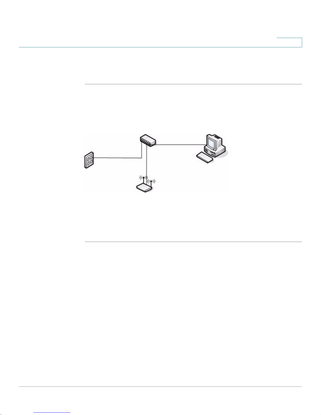
Connecting the Access Point to the PC through a Network Connection
To connect the access point to an administration PC through the network:
STEP 1 Connect one end of an Ethernet straight-through or crossover cable to the network
port on the access point, as shown in Figure 2.
STEP 2 Connect the other end to the same hub or switch where your PC is connected.
Figure 2 Connecting the Access Point Using a LAN Connection
1
The hub or switch you use must permit broadcast signals from the access point to
reach the other devices on the network.
STEP 3 If you are not using PoE, connect the power adapter to the power port on the back
of the access point, then plug the other end of the power cord into a power outlet.
Cisco AP 541N Dual-band Single-radio Access Point Quick Start Guide 10
Page 14

1
Getting Started
Connecting the Access Point to a PC
Launching the Access Point Configuration Utility
This section contains information for the for launching the Access Point
Configuration Utility:
• Using the default static IP address of the switch. Follow the instructions in the
“Display the Configuration Utility By Using the Default IP Address”
section.
• Using Cisco Configuration Assistant (CCA). Follow the instructions in the
“Display the Configuration Utility by Using Cisco Configuration Assistant
2.1 or higher” section.
• Using the an IP address assigned to the switch through DHCP. Follow the
instructions in the “Display the Configuration Utility by Using Another IP
Address” section.
Display the Configuration Utility By Using the Default IP
Address
To a c ce s s t he Access Point Configuration Utility, enter the default static IP
address of the access point into a Web browser, do the following:
STEP 1 Enter the Cisco AP 541N default static IP address in the address bar and press Enter. For
example, http://
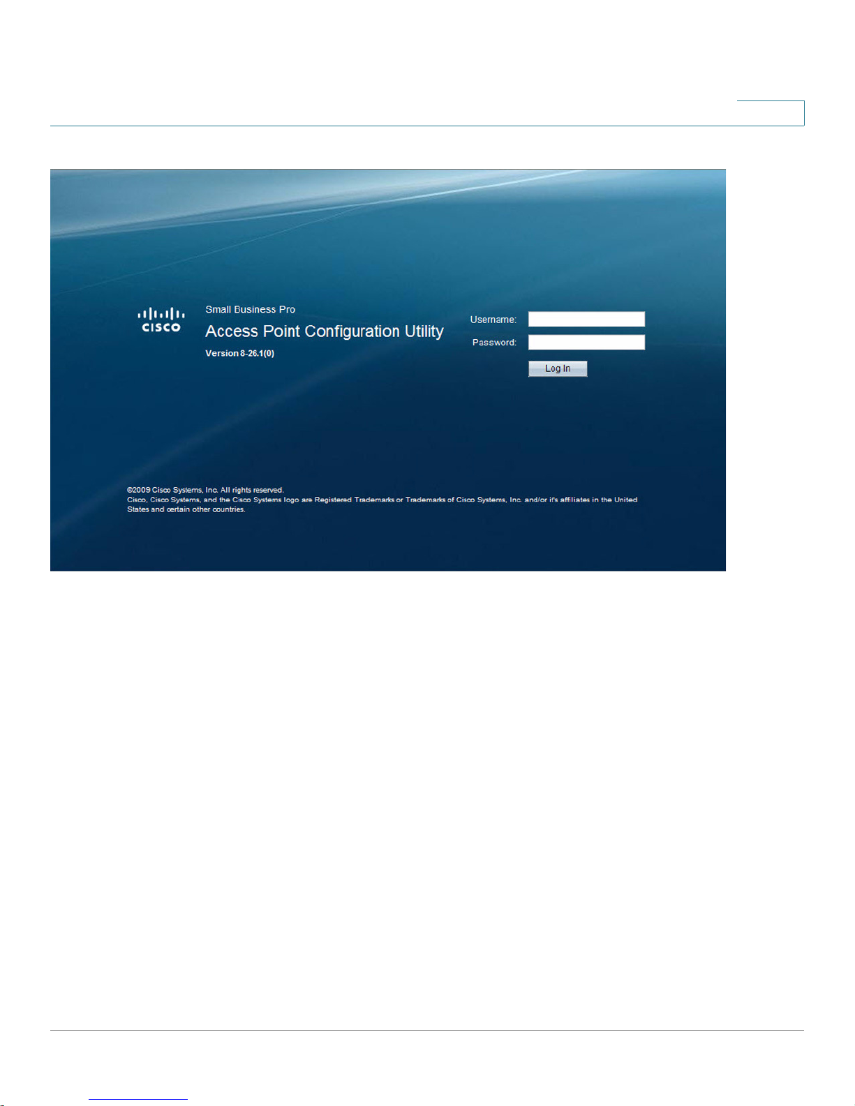
The Login window displays, as shown in Figure 3.
192.168.10.10.
11 Cisco AP 541N Dual-band Single-radio Access Point Quick Start Guide
Page 15
Getting Started
Connecting the Access Point to a PC
Figure 3 Login Window
1
STEP 2 Enter the login information:
Username = cisco
Default password cisco. (Passwords are case sensitive.)
When you log in, the Getting Started page for the access point Configuration
Utility is displayed, as shown in Figure 4.
Cisco AP 541N Dual-band Single-radio Access Point Quick Start Guide 12
Page 16

1
Getting Started
Connecting the Access Point to a PC
Figure 4 Getting Started Page
STEP 3 Update the Cisco AP 541N software with the latest version by clicking the Software
Upgrade link,
Next, we recommend that you:
• Change the password by clicking Change Administrator Password.
• Configure the SSID and enable wireless security, by clicking Configure
• Enable the wireless radio, by clicking Enable Wireless Radio.
• Assign a new static IP address to the access point if your network devices
as shown in Figure 4.
Wireless Networks (SSIDs).
are configured with static IP addresses, by clicking Set LAN IP Address.
13 Cisco AP 541N Dual-band Single-radio Access Point Quick Start Guide
Page 17
Getting Started
195058
Internet
DHCP client
Connecting the Access Point to a PC
Display the Configuration Utility by Using
Cisco Configuration Assistant 2.1 or higher
Use Cisco Configuration Assistant 2.1 or higher (CCA) to configure the access
point when it is deployed in a Cisco Smart Business Communications System
(SBCS) network with a UC520 or SR520.
1
This procedure assumes you are familiar with CCA. You can find additional
information about CCA at http://www.cisco.com/en/US/products/ps7287/
tsd_products_support_series_home.html
To configure the access point by using CCA:
STEP 1 Connect the Ethernet port on the access point to a switch port on a SBCS device.
STEP 2 Power on the Cisco AP541N.
STEP 3 Connect a PC with CCA installed to any access switch port on the UC520 or
SR520.
STEP 4 Create a new CCA site by entering a name and the IP address of the UC520 or
SR520.
STEP 5 Connect to the CCA site by using the appropriate login credentials.
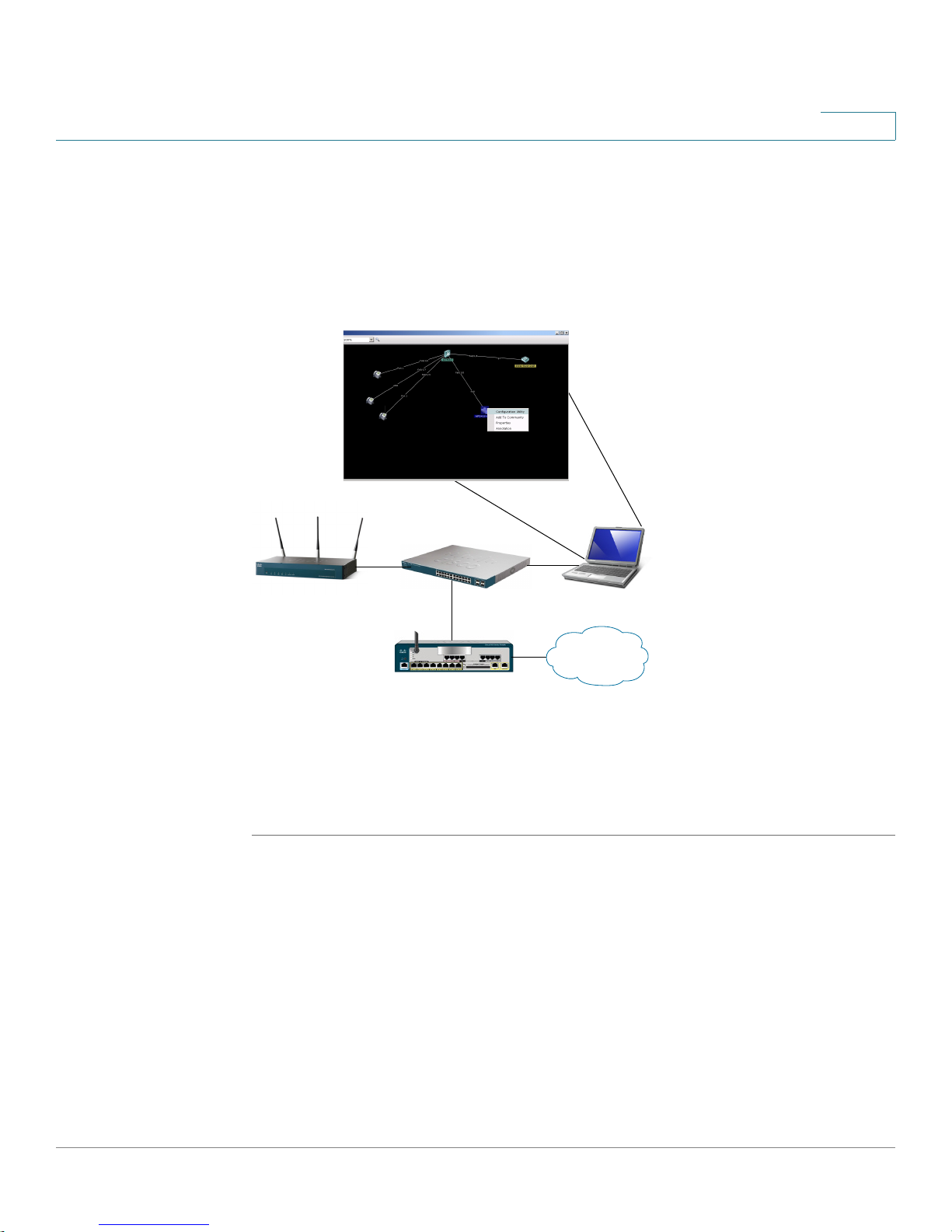
STEP 6 Click Window > Top olo gy Vi ew.
Cisco AP 541N Dual-band Single-radio Access Point Quick Start Guide 14
Page 18

1
Getting Started
Connecting the Access Point to a PC
When you have connected to the CCA site and the devices have been discovered,
the Topology Map includes the Cisco AP541N.
NOTE Non-Cisco devices connected to the switch are not shown in the Topology
map.
STEP 7 Right-click the access point to display the options: Configuration Utility,
Properties, and Annotation.
STEP 8 Click Configuration Utility.
The Access Point Configuration Utility
Figure 4.
Next, we recommend that you:
• Change the password by clicking Change Administrator Password.
• Configure the SSID and enable wireless security, by clicking Configure
Wireless Networks (SSIDs).
• Enable the wireless radio, by clicking Enable Wireless Radio.
• Assign a new static IP address to the access point if your network devices
are configured with static IP addresses, by clicking Set LAN IP Address.
displays in a new window, as shown in
15 Cisco AP 541N Dual-band Single-radio Access Point Quick Start Guide
Page 19

Getting Started
!
Connecting the Access Point to a PC
Display the Configuration Utility by Using Another IP Address
You can display the Access Point Configuration Utility by using an IP address
assigned to the access point during a previous configuration or by a DHCP server.
When you power on the access point, the built-in DHCP client searches for a
DHCP server on the network to obtain an IP address and other network
information. If the access point does not find a DHCP server on the network, the
access point uses its default static IP address (192.168.10.10) unless you have
assigned it a static IP address (and specified a static IP addressing policy) or until
the access point successfully receives network information from a DHCP server.
CAUTION If the acce ss p oint IP addres s is chan ged, eithe r by a DHCP s erver or manually, your
link to the access point will be lost and you must enter the new IP address to use
the Access Point Configuration Utility.
1
To configure the access point by using an IP address other than the default static
IP address:
STEP 1 Power on the Cisco AP541N.
STEP 2 If you used a DHCP server on your network to automatically configure network
information for the access point, enter the IP address assigned to the access point
by the DHCP server into the Web browser.
If you have access to the DHCP server on your network and know the MAC
address of your access point, you can view the new IP address associated with
the MAC address of the access point. Otherwise, we recommend that you
disconnect the access point from the network, reset it to the default configuration
by using the procedure in the “Resetting the Device by using the Reset Button”
section, and configuring the device by using the procedure in the “Display the
Configuration Utility By Using the Default IP Address” section.
If you replaced the default static IP address with a new static IP address, enter the
new IP address of the access point into the Web browser
The Login window displays, as shown in Figure 3.
STEP 3 Enter the login information:
Username is cisco
Default password is cisco (passwords are case sensitive)
Cisco AP 541N Dual-band Single-radio Access Point Quick Start Guide 16
Page 20

1
Getting Started
Connecting the Access Point to a PC
When you log in, the Getting Started page for the access point Configuration
Utility is displayed, as shown in Figure 4.
STEP 4 Update the Cisco AP 541N software with the latest version by clicking the Software
Upgrade link,
Next, we recommend that you:
• Change the password by clicking Change Administrator Password.
• Configure the SSID and enable wireless security, by clicking Configure
• Enable the wireless radio, by clicking Enable Wireless Radio.
• Assign a new static IP address to the access point if your network devices
as shown in Figure 4.
Wireless Networks (SSIDs).
are configured with static IP addresses, by clicking Set LAN IP Address.
!
CAUTION If you do not have a DHCP server on your internal network, and do not plan to use
one, we recommend assigning a new static IP address so that if you bring up
another WLAN Cisco AP541N on the same network, the IP address for each access
point is unique. If the IP address is not unique, a conflict results causing
unpredictable results.
To change the connection type and assign a static IP address by using the Access
Point Configuration Utility, see LAN Settings, page 40.
17 Cisco AP 541N Dual-band Single-radio Access Point Quick Start Guide
Page 21

Getting Started
Troubleshooting Your Connection
Troubleshooting Your Connection
If you cannot display the login window, you can test the IP address by using the
ping command. If you do not know the IP address, you can configure the device by
resetting the device to the factory defaults and accessing the Access Point
Configuration Utility by using the factory default static IP address.
Using the Ping Command to Test the Connection
If you cannot display the configuration utility, you can test the ability of the PC to
communicate with the access point by using ping. To use ping on a PC running
Windows:
STEP 1 Verify that the Cisco AP 541N is powered on and the LEDs indicate the
appropriate links.
1
STEP 2 Open a command window by using Start > Run and enter cmd.
STEP 3 At the Command window prompt enter ping and the access point IP
address. For example ping 192.168.10.10 (the default static IP address of the
access point).
If successful, you should get a reply similar to the following:
Pinging 192.168.10.10 with 32 bytes of data:
Reply from 192.168.10.10: bytes=32 time<1ms TTL=128
Reply from 192.168.10.10: bytes=32 time<1ms TTL=128
Reply from 192.168.10.10: bytes=32 time<1ms TTL=128
If it fails, likely you are using the wrong access point IP address and you will get a
reply similar to the following:
Pinging 192.168.10.10 with 32 bytes of data:
Request timed out.
Possible Cause of Failure
The most likely cause of connectivity failure is an incorrect IP address.
The Web browser is pointed to the wrong IP address. Or, your PC might be
configured with an IP address that is not in the same subnet as the access point.
Cisco AP 541N Dual-band Single-radio Access Point Quick Start Guide 18
Page 22

1
Getting Started
Troubleshooting Your Connection
DHCP is enabled on the Cisco AP 541N by default. When a DHCP server is
enabled on your network and the access point is connected to the network, the
DHCP server replaces the default static IP address with a DHCP server–assigned
IP address. If this happens before you display the Access Point Configuration
Utility window, you must use the assigned IP address to display the utility. If this
happens during configuration, the Access Point Configuration Utility will lose
connectivity.
You can query the DHCP server for the new IP address or disconnect the access
point from the network and reset the device to use the static default access point
IP address by using the Resetting the Access Point to the Factory Default
Configuration, page 121 procedure.
Resetting the Device by using the Reset Button
To use the Reset button to reboot or reset the access point, do the following:
• To reboot the access point, press the Reset button. Do not hold it for more
than 10 seconds.
• To restore the access point to the factory default settings:
1. Disconnect the access point from the network or disable all DHCP
servers on your network.
2. With the power on, press-and-hold the Reset button for more than 10
seconds.
19 Cisco AP 541N Dual-band Single-radio Access Point Quick Start Guide
Page 23

Getting Started
Configuring the Access Point by using the Getting Started Page
Configuring the Access Point by using the Getting Started
Page
From the Getting Started page, you can use the following links to quickly configure
your access point:
• Access Point Configuration
• Access Point Management Page
• Wireless Configuration Page
Access Point Configuration
To change the access point IP address, password, and VLAN configuration, do the
following:
1
STEP 1 Click Change Administrator Password to provide a new administration password
for the access point. (The username is cisco and it cannot be changed. The default
password is cisco.)
STEP 2 If you do not have a DHCP server on the network and do not plan to use one, click
Change IP Address to change the connection type from DHCP to static IP and set
a static IP address and subnet mask.
NOTE We recommend that you assign a new static IP address. Otherwise, if you
bring up another Cisco AP 541N on the same network, the IP address for
each access point will not be unique; duplicating an IP address on a network
will create a conflict.
Also, if you change the static IP address, you will lose connectivity. To
reestablish connectivity, enter the new IP address into your Web browser
and log into the Configuration Utility.
To change the connection type and assign a static IP address, see LAN
Settings, page 40.
Cisco AP 541N Dual-band Single-radio Access Point Quick Start Guide 20
Page 24

1
Getting Started
Wireless Client Requirements
STEP 3 If your network uses VLANs, you might need to configure the management VLAN
ID or untagged VLAN ID on the access point for it to work with your network.
For information about how to configure VLAN information, see LAN Settings, page
40.
STEP 4 If your network uses Dynamic WEP port security for network access control, you
must configure the 802.1X supplicant information on the access point. For
information about how to configure the 802.1X user name and password, see
Configuring 802.1X Authentication, page 43.
Access Point Management Page
Click System Information to view the device information. For more information, see
Device Information, page 27.
As new versions of the Access Point software become available, you can upgrade
the software on your devices to take advantage of new features and
enhancements. For more information, see Software Upgrade, page 124.
For information on how to backup and restore the configuration, go to Access
Point Configuration, page 120.
Wireless Configuration Page
For information about the wireless radio settings, see Configuring Wireless Radio
Settings, page 160.
To configure the SSID, Guest Access, and Security Configuration, see Modifying
Virtual Access Point Settings, page 55.
Wireless Client Requirements
The access point provides wireless access to any client with a properly
configured Wi-Fi client adapter for the 802.11 mode in which the access point is
running. The access point supports multiple client operating systems. Clients can
be laptop or desktop computers, personal digital assistants (PDAs), or any other
hand-held, portable or stationary device equipped with a Wi-Fi adapter and
supporting drivers.
21 Cisco AP 541N Dual-band Single-radio Access Point Quick Start Guide
Page 25

Getting Started
Wireless Client Requirements
1
To connect to the access point, wireless clients need the software and hardware
described in Ta b le 2 .
Table 2 Requirements for Wireless Clients
Required Component Description
Wi-Fi Client Adapter Portable or built-in Wi-Fi client adapter that supports
one or more of the IEEE 802.11 modes in which you
plan to run the access point. (IEEE 802.11a, 802.11b,
802.11g, and 802.11n modes are supported.)
Wireless Client
Software
Client Security
Settings
Client software, such as Microsoft Windows
Supplicant, configured to associate with the access
point.
Security should be disabled on the client used to do
initial configuration of the access point.
If the Security mode on the access point is set to
anything other than plain text, wireless clients must
have a profile set to the same authentication mode
used by the access point and provide a valid username
and password, certificate, or user identity required by
the authentication server. Security modes are Static
WEP, IEEE 802.1X, WPA with RADIUS server, and WPA-
PSK.
For information about configuring security on the
access point, see Configuring the Wireless
Distribution System, page 91.
Cisco AP 541N Dual-band Single-radio Access Point Quick Start Guide 22
Page 26

1
Verifying the Installation
Make sure the access point is connected to the LAN and associating with wireless
clients on the network. Once you have tested the basics of your wireless network,
you can enable more security and fine-tune the access point by modifying the
advanced configuration features.
STEP 1 Connect the access point to the LAN.
If you configured the access point by using a direct cable connection from your
computer to the access point, do the following:
a. Disconnect the cable from the computer and the access point.
b. Mount the access point in the desired location.
Getting Started
Verifying the Installation
c. Connect an Ethernet cable from the access point to the LAN.
d. Power on the access point.
e. Connect your computer to the LAN by using an Ethernet cable or a wireless
card.
If you configured the access point and an administrator PC by connecting both to
a network hub or switch, your access point is already connected to the LAN. The
next step is to test some wireless clients.
STEP 2 Test the access point by trying to detect it and associate with it from a wireless
client. For information about requirements for the client devices, see Wireless
Client Requirements, page 21.
NOTE The access point is not designed for multiple, simultaneous configuration
changes. If more than one administrator is logged onto the Configuration
Utility and is making changes to the configuration, there is no guarantee that
all configuration changes specified by multiple users will be applied.
23 Cisco AP 541N Dual-band Single-radio Access Point Quick Start Guide
Page 27

Getting Started
!
Configuring Security on the Wireless Access Point
CAUTION By default, no security is in place on the access point, so any wireless client can
associate with it and access your LAN, including unauthorized devices. An
important next step is to configure security. Continue with Configuring Security on
the Wireless Access Point, page 24 for more information.
Configuring Security on the Wireless Access Point
You configure secure wireless client access by configuring security for each
virtual access point (VAP) that you enable. You can configure up to 16 VAPs per
wireless radio that simulate multiple access points in one physical access point.
For each VAP, you can configure a unique security mode to control wireless client
access.
1
Ea ch w irel es s r adi o h as 1 6 VA Ps , wi t h VA P I D s f ro m 0-15 . VA P 0, VAP 1, a nd VA P 2
have di f fer en t d e fa ul t s e t ti ng s th an VA Ps 3-15 . B y d e fa ul t , VAP 0 , VA P 1, a nd VA P 2
are enabled.
VAP0 has the following default settings:
• VLAN ID: 1
• SSID: cisco-data
• Broadcast SSID: Enabled
• Security: None
• MAC Authentication Type: Disabled
• Station Isolation: Disabled
• HTTP Redirect: Disable
VAP1 has the following default settings:
• VLAN ID: 100
• SSID: cisco-voice
• Broadcast SSID: Enabled
• Security: None
• MAC Authentication Type: Disabled
Cisco AP 541N Dual-band Single-radio Access Point Quick Start Guide 24
Page 28

1
Getting Started
Configuring Security on the Wireless Access Point
• Station Isolation: Disabled
• HTTP Redirect: Disable
VAP2 has the following default settings:
• VLAN ID: 1
• SSID: cisco-scan
• Broadcast SSID: Enabled
• Security: WPA Personal
• WPA Versions: WPA2
• Cipher Suites: CCMP (AES)
• Key: intermec
• MAC Authentication Type: Disabled
• Station Isolation: Disabled
• HTTP Redirect: Disable
VAP3-15 are disabeld by default, but when they are enabled they will have the
following default settings:
• VLAN ID: 1
• SSID: Virtual Access Point x ( where x is the VAP ID)
• Broadcast SSID: Enabled
• Security: None
• MAC Authentication Type: Disabled
• Station Isolation: Disabled
• HTTP Redirect: Disable
To prevent unauthorized access to the access point, we recommend that you
select and configure a security option other than None for the default VAP and for
each VAP that you enable.
For information about how to configure the security settings on each VAP, see
Configuring the Wireless Distribution System, page 91.
25 Cisco AP 541N Dual-band Single-radio Access Point Quick Start Guide
Page 29

Status
2
The Status page provides information on the following:
• Device Information
• Network Interfaces
• Traffic Statistics
• Associated Clients
• Rogue AP Detection
Cisco AP 541N Dual-band Single-radio Access Point Quick Start Guide 26
Page 30
2
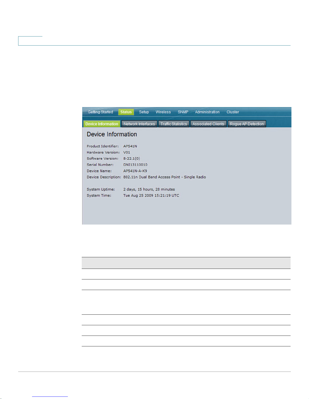
Device Information
From the Device Information page, you can view hardware and product
information.
Figure 5 Device Information
Status
Device Information
Ta bl e 3 describes the fields shown on the Device Information page.
Tab le 3 D e vi ce In fo rm ati on Pa ge
Field Description
Product Identifier
Hardware Version
Software Version
Serial Number
Device Name
Device Description
27 Cisco AP 541N Dual-band Single-radio Access Point Quick Start Guide
Identifies the AP hardware model.
Identifies the AP hardware version.
Shows version information for the software installed on the
AP. As new versions of the WLAN AP software become
available, you can upgrade the software.
Shows the AP serial number.
Generic name to identify the type of hardware.
Provides information about the product hardware.
Page 31

Tab le 3 D e vi ce In for m ati on Pa ge
Field Description
2
System Uptime
Network Interfaces
The Network Interface Status window displays the current Wired Settings and
the Wireless Settings of the access point. Click Refresh to refresh the page.
Figure 6 Interface Status
The amount of time that the AP has been operational since
its last power-up/reboot.
Cisco AP 541N Dual-band Single-radio Access Point Quick Start Guide 28
Page 32

2
Status
Traffic Statistics
Wired Settings
The Wired Settings include the MAC address, management VLAN ID, IP address,
subnet mask, and DNS information. To change any of these settings, click Edit to
be redirected to the Setup > LAN Settings page.
For information about configuring these settings, see LAN Settings, page 40.
Wireless Settings
The Wireless Settings section indicates the status of the wireless radio, and
includes the Radio Mode and Channel. The Wireless Settings section also shows
the MAC address (read-only) associated with each wireless radio interface.
To change the Radio Mode or Channel settings, click Edit. You are redirected to the
Wireless > Radio Settings page.
For information about configuring these settings, see Modifying Wireless Radio
Settings, page 52 and Modifying Advanced Settings, page 79.
Traffic Statistics
The Traffic Statistics page provides basic information about the access point, a
real-time display of the transmit and receive statistics for the Ethernet interface,
and VAP (Virtual Access Point) statistics. The transmit and receive statistics are
totals since the access point was last started. If you reboot the access point, these
figures indicate transmit and receive totals since the reboot.
To view transmit and receive statistics for the access point, click the Traffic
Statistics tab. Click Refresh to refresh the page.
29 Cisco AP 541N Dual-band Single-radio Access Point Quick Start Guide
Page 33

Status
Traffic Statistics
2
Figure 7 Viewing Traffic Statistics
Cisco AP 541N Dual-band Single-radio Access Point Quick Start Guide 30
Page 34

2
Status
Traffic Statistics
Table 4 Traffic Statistics Description
Field Description
Network Interfaces
Status
MAC Address
The name of the Ethernet or VAP interfaces.
Shows whether the interface is up or down.
MAC address for the specified interface. Each VAP
interface has a unique MAC address.
VLAN ID
A virtual LAN (VLAN) ID is used to establish multiple
networks on the same access point. The VLAN ID is
configured on the Wireless > VAP tab. (See Bandwidth
Utilization, page 96.)
Name (SSID)
The network name, also known as the SSID, is an
alphanumeric key that uniquely identifies a VAP. The
name (SSID) is configured on the VAP tab. (See
Bandwidth Utilization, page 96.) NA means either that
the entry is not applicable or is not supported.
Transmit and Receive Information
Total Packets
Indicates total packets sent (in Transmit table) or
received (in Received table) on that interface.
Total Bytes
Indicates total bytes sent (in Transmit table) or
received (in Received table) on that interface.
Total Dropped Packets
Indicates total number of packets sent (in Transmit
table) or received (in Received table) on that interface
that were dropped. NA means that the drop and error
counters for the VAP interfaces and the WDS
interfaces are not supported.
Total Dropped Bytes
Indicates total number of bytes sent (in Transmit table)
or received (in Received table) on that interface that
were dropped. NA means that the drop and error
counters for the VAP interfaces and the WDS
interfaces are not supported.
Errors
Displays the total number of transmit and receive
errors detected by the AP. NA means that the drop and
error counters for the VAP interfaces and the WDS
interfaces are not supported.
31 Cisco AP 541N Dual-band Single-radio Access Point Quick Start Guide
Page 35

Status
Associated Clients
Associated Clients
To view the client stations associated with the access point, click the Associated
Clients tab.
Figure 8 Viewing Client Association Information
2
The associated stations are displayed along with information about packet traffic
transmitted and received for each station. Click Refresh to refresh the page.
Ta bl e 5 describes the fields on the Associated Clients page.
Table 5 Associated Clients Field Descriptions
Field Description
Network
Station
Shows which VAP the client is associated with. For
example, an entry of wlan0vap2 means the client is
associated with Wireless Radio 1, VAP 2.
Shows the MAC address of the associated wireless
client.
Cisco AP 541N Dual-band Single-radio Access Point Quick Start Guide 32
Page 36

2
Status
Associated Clients
Table 5 Associated Clients Field Descriptions
Field Description
Status
The Authenticated and Associated Status shows the
underlying IEEE 802.11 authentication and association
status that is present no matter which type of security the
client uses to connect to the access point. This status
does not show the IEEE 802.1X authentication or
association status.
Some points to keep in mind with regard to this field are:
• If the AP security mode is None or Static WEP, the
authentication and association status of clients
showing on the Client Associations tab will be in
line with what is expected; that is, if a client shows
as authenticated to the access point, it will be able
to transmit and receive data. (This is because
Static WEP uses only IEEE 802.11 authentication.)
• If the access point uses IEEE 802.1X or WPA
security, however, it is possible for a client
association to show on this tab as authenticated
(by using IEEE 802.11 security) but actually not be
authenticated to the access point by using the
second layer of security.
From Station
To Station
33 Cisco AP 541N Dual-band Single-radio Access Point Quick Start Guide
Shows the number of packets and bytes received from
the wireless client and the number of packets and bytes
that were dropped after being received.
Shows the number of packets and bytes transmitted
from the access point to the wireless client and the
number of packets and bytes that were dropped upon
transmission.
Page 37

Status
Rogue AP Detection
Link Integrity Monitoring
The access point provides link integrity monitoring to continually verify its
connection to each associated client. To do this, the access point sends data
packets to clients every few seconds when no other traffic is passing. This allows
the access point to detect when a client goes out of range, even during periods
when no normal traffic is exchanged. The client connection drops off the list within
300 seconds if these data packets are not acknowledged, even if no
disassociation message is received.
Rogue AP Detection
A Rogue AP is an access point that has been installed on a secure network without
authorization from a system administrator. Rogue access points pose a security
threat because anyone with access to the premises can ignorantly or maliciously
install a wireless access point that might allow unauthorized parties to access the
network.
2
The Rogue AP Detection page displays information about all access points
detected by the Cisco AP 541N in the vicinity of the network. If the access point
listed as a rogue is actually a legitimate access point, you can add it to the Known
AP List. Click Refresh to refresh the page.
NOTE The Detected Rouge AP List and Known AP List provide information. The Cisco
AP 541N does not have any control over the access points on the lists and cannot
apply any security policies to access points detected through the RF scan.
Cisco AP 541N Dual-band Single-radio Access Point Quick Start Guide 34
Page 38

2
Status
Rogue AP Detection
Figure 9 Viewing Neighboring Access Points
You must enable the access point detection to collect information about other
access points within range. Ta b le 6 describes the information provided on
neighboring access points.
Table 6 Neighboring Access Point Information
Field Description
AP Detection
To enable neighbor access point detection and collect
information about neighbor access points, click Enabled.
(default)
To disable neighbor access point detection, click Disabled.
To save the setting, click Apply.
35 Cisco AP 541N Dual-band Single-radio Access Point Quick Start Guide
Page 39

Status
Rogue AP Detection
2
Table 6 Neighboring Access Point Information
Field Description
Action
MAC
Beacon Int.
If an access point is in the Detected Rogue AP List, you can
click Grant to move the access point from the Detected
Rogue AP List to the Known AP List.
If an access point is in the Known AP List, click the Delete
button to move the access point from the Known AP List to
the Detected Rogue AP List.
NOTE: The Detected Rouge AP List and Known AP List
provide information only; the Cisco AP 541N does not have
any control over the access points on the list and cannot
apply any security policies to access points detected
through the RF scan.
Shows the MAC address of the detected access point.
Shows the Beacon interval of another access point.
Beacon frames are transmitted by an access point at regular
intervals to announce their existence on the wireless
network. The default behavior is to send a beacon frame
once every 100 milliseconds (or 10 per second).
The Beacon Interval for your access point is set on the
Wireless > Advanced Settings page. (See Modifying
Advanced Settings, page 79.)
Type
Cisco AP 541N Dual-band Single-radio Access Point Quick Start Guide 36
Indicates the type of device:
• AP indicates the detected device is an access point
that supports the IEEE 802.11 Wireless Networking
Framework in Infrastructure Mode.
• Ad hoc designation indicates a neighboring station
running in ad hoc mode. Stations set to ad hoc mode
communicate with each other directly, without the use
of a traditional access point. Ad-hoc mode is an IEEE
802.11 Wireless Networking Framework also referred
to as peer-to-peer mode or an Independent Basic
Service Set (IBSS).
Page 40

2
Status
Rogue AP Detection
Table 6 Neighboring Access Point Information
Field Description
SSID
Privacy
WPA
The Service Set Identifier (SSID) for another, detected
access point.
The SSID is an alphanumeric string of up to 32 characters
that uniquely identifies a wireless local area network. It is
also referred to as the Network Name.
The SSID is set on the Virtual Access Point tab. (See
Bandwidth Utilization, page 96.)
Indicates whether there is any security on the neighboring
access point.
• Off indicates that the Security mode on the
neighboring access point is set to None (no security).
• On indicates that the neighboring access point has
some security in place.
Security is configured on the access point from the Virtual
Access Point page.
Indicates whether WPA security is on or off for the detected
access point.
Band
37 Cisco AP 541N Dual-band Single-radio Access Point Quick Start Guide
This indicates the IEEE 802.11 mode being used on the
detected access point. (For example, IEEE 802.11a, IEEE
802.11b, IEEE 802.11g.)
The number shown indicates the mode according to the
following map:
• 2.4 indicates IEEE 802.11b, 802.11g, or 802.11n mode
(or a combination of the modes)
• 5 indicates IEEE 802.11a mode, 802.11n mode, or a
combination of modes.
Page 41

Status
Rogue AP Detection
2
Table 6 Neighboring Access Point Information
Field Description
Channel
Rate
Signal
Beacons
Shows the Channel on which the detected access point is
broadcasting.
The channel defines the portion of the wireless radio
spectrum that the wireless radio uses for transmitting and
receiving.
The channel for your access point is set in Wireless >
Advanced Settings. (See Modifying Advanced Settings,
page 79.)
Shows the rate (in megabits per second) at which the
detected access point is currently transmitting.
The current rate is always one of the rates shown in
Supported Rates.
Indicates the strength of the wireless radio signal emitting
from the detected access point. If you hover the mouse
pointer over the bars, a number appears and shows the
strength in decibels (dB).
Shows the total number of beacons received from the
detected access point since it was first discovered.
Last Beacon
Rates
Cisco AP 541N Dual-band Single-radio Access Point Quick Start Guide 38
Shows the date and time of the last beacon received from
the detected access point.
Shows supported and basic (advertised) rate sets for the
detected access point. Rates are shown in megabits per
second (Mbps).
All Supported Rates are listed, with Basic Rates shown in
bold.
Rate sets are configured on the Wireless > Advanced
Settings page. (See Modifying Advanced Settings, page
79.)
Page 42

2
Status
Rogue AP Detection
Save or Import a List of Known Access Points
To save the Known AP List to a file, click Save. The list contains the MAC
addresses of all access points that have been added to the Known AP List. By
default, the filename is Rogue2.cfg. You can use a text editor or Web browser to
open the file and view its contents.
Use the Import feature to import a list of known access points from a saved list.
The list might be from another Cisco access point or created from a text file. If the
MAC address of an access point appears in the Known AP List, it will not be
shown as a rogue.
The file you import must be a plain-text file with a .txt or .cfg extension. Entries in
the file are MAC addresses in hexadecimal format with each octet separated by
colons, for example 00:11:22:33:44:55. Separate the entries with a single space.
For the access point to accept the file, it must contain only MAC addresses.
To import an access point list from a file, do the following:
STEP 1 Choose whether to replace the existing Known AP List or add the entries in the
imported file to the Known AP List.
• Select the Replace radio button to import the list and replace the entire
contents of the Known AP List.
• Select the Merge radio button to import the list and add the access points
in the imported file to the access points currently displayed in the Known
AP List.
STEP 2 Click Browse and choose the file to import.
STEP 3 Click Import.
Once the import is complete, the screen refreshes and the MAC addresses of
the access points listed in the imported file appear in the Known AP List.
39 Cisco AP 541N Dual-band Single-radio Access Point Quick Start Guide
Page 43

Setup
LAN Settings
3
The default wired LAN interface settings, including the default DHCP and VLAN
parameters, might not work correctly for your network.
By default, the DHCP client on the access point broadcasts requests for network
information. To use a static IP address, you must disable the DHCP client and
manually configure the IP address and other network information.
The access point default management VLAN is VLAN 1. This VLAN is also the
default untagged VLAN. If you have configured the management VLAN on your
network with a different VLAN ID, you must change the VLAN ID of the access
point management VLAN.
To configure the LAN interface settings, click the LAN Settings tab.
Cisco AP 541N Dual-band Single-radio Access Point Quick Start Guide 40
Page 44

3
Setup
LAN Settings
Figure10 LAN Settings
41 Cisco AP 541N Dual-band Single-radio Access Point Quick Start Guide
Page 45

3
Ta bl e 7 describes the fields to view or configure on the LAN Settings page.
Table 7 LAN Settings Field Descriptions
Field Description
Hostname
MAC Address
Management
VLAN ID
Untagged VLAN
DNS name (host name) for the access point.
The DNS name has the following requirements:
• Maximum of 20 characters
• Only letters, numbers and dashes. Double quote (") is
not a valid character.
• Must start with a letter and end with either a letter or a
number
MAC address for the Ethernet port on this access point. This
is a read-only field that you cannot change.
Enter a number between 1 and 4094 for the management
VLAN ID used on your network.
The default management VLAN ID is 1.
Enable or disable VLAN tagging. If you enable the untagged
VLAN, all traffic is tagged with a VLAN ID.
By default all traffic on the access point uses VLAN 1, the
default untagged VLAN. This means that all traffic is
untagged until you disable the untagged VLAN, change the
untagged traffic VLAN ID, or change the VLAN ID for a VAP or
client using RADIUS.
Untagged VLAN
ID
Connection
Ty pe
Cisco AP 541N Dual-band Single-radio Access Point Quick Start Guide 42
Provide a number between 1 and 4094 for the untagged
VLAN ID. Traffic on the VLAN that you specify in this field is
not tagged with a VLAN ID.
If you select DHCP, the access point acquires its IP address,
subnet mask, DNS, and gateway information from a DHCP
server.
If you select Static IP, you must enter information in the Static
IP Address, Subnet Mask, and Default Gateway fields.
Page 46

3
Setup
Configuring 802.1X Authentication
Table 7 LAN Settings Field Descriptions
Field Description
Static IP
Address
Subnet Mask
Default
Gateway
DNS
Nameservers
NOTE After you configure the wired settings, you must click Apply to apply the changes
and to save the settings. Changing some settings might cause the access point to
stop and restart system processes. If this happens, wireless clients temporarily
lose connectivity. We recommend that you change AP settings when WLAN traffic
is low.
The static IP address of the access point. This field is
disabled if you use DHCP as the connection type.
Subnet Mask of the access point.
Default Gateway of the access point.
DNS mode.
In Dynamic mode, the IP addresses for the DNS servers are
assigned automatically by using DHCP. This option is only
available if you specified DHCP for the Connection Type.
In Manual mode, you must assign the IP addresses of the
DNS Nameservers that resolve domain names.
Configuring 802.1X Authentication
On networks that use IEEE 802.1X, port-based network access control, a
supplicant (client) cannot gain access to the network until the 802.1X
authentication server grants access. If your network uses 802.1X, you must
configure the 802.1X authentication information that the access point can supply to
the authentication server.
To configure the access point 802.1X supplicant user name and password, click
the 802.1X Authentication tab and configure the fields shown in Ta bl e 8 .
43 Cisco AP 541N Dual-band Single-radio Access Point Quick Start Guide
Page 47

Setup
Configuring 802.1X Authentication
Figure11 IEEE 802.1X Authentication
3
Table 8 IEEE 802.1X Authentication Field Descriptions
Field Description
802.1X Supplicant
Cisco AP 541N Dual-band Single-radio Access Point Quick Start Guide 44
Click Enabled to enable the Administrative status of the
802.1X Supplicant.
Click Disabled to disable the Administrative status of the
802.1X Supplicant.
Page 48

3
Setup
Configuring 802.1X Authentication
Table 8 IEEE 802.1X Authentication Field Descriptions
Field Description
Username
Password
NOTE After you configure the settings on the Authentication page, you must click Apply
to apply the changes and to save the settings. Changing some settings might cause
the access point to stop and restart system processes. If this happens, wireless
clients will temporarily lose connectivity. We recommend that you change access
point settings when WLAN traffic is low.
Enter the MD5 username for the access point to use when
responding to requests from an 802.1X authentication server.
The username can be 1 to 64 characters in length. ASCII
printable characters are allowed, which includes upper and
lower case letters, numbers, and special symbols such as @
and #. Double quote (") is not a valid character.
NOTE: If the 802.1X Supplicant is Disabled, the Username
field is not editable.
Enter the MD5 password for the access point to use when
responding to requests from an 802.1X authentication server.
The password can be 1 to 64 characters in length. ASCII
printable characters are allowed, which includes upper and
lower case letters, numbers, and special symbols such as @
and #. Double quote (") is not a valid character.
NOTE: If the 802.1X Supplicant is Disabled, the Password
field is not editable.
45 Cisco AP 541N Dual-band Single-radio Access Point Quick Start Guide
Page 49

Setup
Enabling the Network Time Protocol
Enabling the Network Time Protocol
The Network Time Protocol (NTP) is an Internet standard protocol that
synchronizes computer clock times on your network. NTP servers transmit
Coordinated Universal Time (UTC, also known as Greenwich Mean Time) to their
client systems. NTP sends periodic time requests to servers, using the returned
time stamp to adjust its clock. The timestamp is used to indicate the date and time
of each event in log messages.
By using NTP, the AP can obtain and maintain its time from a server on the network.
Using an NTP server gives your AP the ability to provide the correct time of day in
log messages and session information.
See http://www.ntp.org for more information about NTP.
To configure the NTP that the access point uses manually as shown in Figure 12
on page 47 or by using a server as shown in Figure 13 on page 48, click the Time
tab and update the fields as described in Ta bl e 9 .
3
Cisco AP 541N Dual-band Single-radio Access Point Quick Start Guide 46
Page 50

3
Setup
Enabling the Network Time Protocol
Figure12 Manually Enabling Network Time Protocol
47 Cisco AP 541N Dual-band Single-radio Access Point Quick Start Guide
Page 51

Setup
Enabling the Network Time Protocol
Figure13 Enabling Network Time Protocol Server
3
Cisco AP 541N Dual-band Single-radio Access Point Quick Start Guide 48
Page 52

3
Setup
Enabling the Network Time Protocol
Table 9 TIme Settings (NTP)
Field Description
System Time Shows the current system time.
Set System Time To permit the AP to poll an NTP server, click Using
Network Time Protocol (NTP).
To set the system time manually, click Manually.
NTP Server This field appears when you select Using Network
Time Protocol (NTP) in the Set System Time field.
If using NTP, specify the server by host name or IP
address.
Using the IP address is not recommended as the IP
address is more likely to change.
Time Zone Select the international time zone in which the AP is
operating, for example USA (Eastern).
System Date This field appears when you select Manually in the
Set System Time field. Use the System Date list to
select month, day, and year.
System Time (24 HR) This field appears when you select Manually in the
Set System Time field. Use the System Time list to
select hours and minutes. All times are relative to the
local time zone.
49 Cisco AP 541N Dual-band Single-radio Access Point Quick Start Guide
Page 53

Setup
Enabling the Network Time Protocol
Table 9 TIme Settings (NTP)
Field Description
3
Adjust Time for Daylight
Savings
DST Start (24 HR) Use this field to configure Daylight Savings Time to
DST End (24 HR) Use this field to configure Daylight Savings Time to
Select the Daylight Savings option to adjust the
system time for Daylight Savings Time (DST). Fields
appear in order to select the date and time to start
and end DST.
start. The start time is relative to standard time. If the
starting month is after the ending month, the system
assumes that you are in the southern hemisphere.
From the week list, select the week of the month
(First, Second, ..., Last).
From the day list, select the day of the week
(Sunday, Monday...).
From the month list, select the month (January,
February...).
Specify the time (24-hour format) by selecting the
hours and minutes.
end. The end time is relative to Daylight Savings
Time .
From the week list, select the week of the month
(First, Second, ..., Last).
From the day list, select the day of the week
(Sunday, Monday...).
From the month list, select the month (January,
February...).
Specify the time (24-hour format) by selecting the
hours and minutes.
DST Offset (minutes) From the DST Offset list, select the number of
minutes to add during Daylight Savings Time (15 to
120 in 15-minute increments).
Cisco AP 541N Dual-band Single-radio Access Point Quick Start Guide 50
Page 54

3
Setup
Enabling the Network Time Protocol
NOTE After you configure the Time settings, you must click Apply to apply the changes
and to save the settings. Changing some settings might cause the access point to
stop and restart system processes. If this happens, wireless clients will temporarily
lose connectivity. We recommend that you change access point settings when
WLAN traffic is low.
51 Cisco AP 541N Dual-band Single-radio Access Point Quick Start Guide
Page 55

Wireless
Modifying Wireless Radio Settings
Wireless settings configure the wireless radio in the access point (802.11 mode
and channel) and to the network interface to the access point (AP MAC address).
To configure the wireless interface, click the Wireless Radio Settings tab.
4
Figure14 Wireless Interface Configuration
Ta bl e 10 describes the fields and configuration options available on the Radio
Settings page.
Cisco AP 541N Dual-band Single-radio Access Point Quick Start Guide 52
Page 56

4
Wireless
Modifying Wireless Radio Settings
Table 10 Radio Settings Field Descriptions
Field Description
Country
802.11d
Regulatory
Domain
Support
The country in which the access point is operating.
Wireless regulations vary from country to country. Make sure
you select the correct country code so that the access point
complies with the regulations in your country. The country
code selection affects the wireless radio modes the access
point can support as well as the list of channels and transmit
power of the wireless radio.
Enabling support for IEEE 802.11d (World Mode) on the access
point causes the access point to broadcast which country it is
operating in as a part of its beacons and probe responses. This
allows client stations to operate in any country without
reconfiguration.
Disabling 802.11d prevents the country code setting from
being broadcast in the beacons. However, this only applies to
wireless radios configured to operate in the
band). For wireless radios operating in the
band), the access point software configures support for
802.11h. When 802.11h is supported, the country code
information is broadcast in the beacons.
g
band (2.4 GHz
a
band (5 GHz
To enable 802.11d regulatory domain support, click Enabled.
To disable 802.11d regulatory domain support, click Disabled.
Wireless
Radio
Interface
MAC Address
53 Cisco AP 541N Dual-band Single-radio Access Point Quick Start Guide
Turns the wireless radio interface on or off.
Indicates the Media Access Control (MAC) addresses for the
interface.
This page shows the MAC addresses for Radio Interface One.
A MAC address is a permanent, unique hardware address for
any device that represents an interface to the network. The
MAC address is assigned by the manufacturer. You cannot
change the MAC address. It is provided here for informational
purposes as a unique identifier for the interface.
Page 57

Table 10 Radio Settings Field Descriptions
Field Description
4
Mode
The Physical Layer (PHY) standard the wireless radio uses.
NOTE: If the Wireless Radio Interface is set to Off, the Mode
cannot be changed.
NOTE: The modes available on your access point depend on
the country code setting.
Select one of the following modes for the wireless radio
interface:
• 802.11a. Only 802.11a clients can connect to the access
point.
• 802.11b/g. 802.11b and 802.11g clients can connect to
the access point.
• 802.11a/n. 802.11a clients and 802.11n clients operating
in the 5-GHz frequency can connect to the access point.
• 802.11b/g/n (default). 802.11b, 802.11g, and 802.11n
clients operating in the 2.4-GHz frequency can connect
to the access point.
• 2.4 GHz 802.11n. Only 802.11n clients operating in the
2.4-GHz frequency can connect to the access point.
• 5 GHz 802.11n.Only 802.11n clients operating in the 5-
GHz frequency can connect to the access point.
Cisco AP 541N Dual-band Single-radio Access Point Quick Start Guide 54
Page 58

4
Wireless
Modifying Virtual Access Point Settings
Table 10 Radio Settings Field Descriptions
Field Description
Channel
NOTE After you configure the wireless settings, you must click Apply to apply the
changes and to save the settings. Changing some settings might cause the access
point to stop and restart system processes. If this happens, wireless clients
temporarily lose connectivity. We recommend that you change access point
settings when WLAN traffic is low.
Select the Channel.
NOTE: If Radio Interface is set to Off, the Channel cannot be
changed.
The range of available channels is determined by the mode of
the wireless radio interface and the country code setting. If
you select Auto for the channel setting, the access point scans
all available channels, immediately selects a channel, and
begins operation. If interference or errors occur on that
channel, another channel is automatically selected.
The Channel defines the portion of the wireless radio
spectrum the wireless radio uses for transmitting and
receiving. Each mode offers a number of channels, depending
on how the spectrum is licensed by national and transnational
authorities such as the Federal Communications Commission
(FCC) or the International Telecommunication Union (ITU-R).
Modifying Virtual Access Point Settings
To change VAP 0 or to enable and configure additional VAPs, select the Virtual
Access Points (SSIDs) tab in the Wireless section.
VAPs segment the wireless LAN into multiple broadcast domains that are the
wireless equivalent of Ethernet VLANs. VAPs simulate multiple access points in
one physical access point. The Cisco AP 541N supports up to 16 VAPs.
55 Cisco AP 541N Dual-band Single-radio Access Point Quick Start Guide
Page 59

Wireless
Modifying Virtual Access Point Settings
NOTE Note that only those VAPs which have non-default configuration are displayed
when the page initially loads. To configure additional VAPs, click Add Another to
expose new (empty) VAP entries.
For each VAP, you can customize the security mode to control wireless client
access. Each VAP can also have a unique SSID. Multiple SSIDs make a single
access point look like two or more access point
By configuring VAPs, you can maintain better control over broadcast and multicast
traffic that affects network performance.
You can configure each VAP to use a different VLAN, or you can configure multiple
VAPs to use the same VLAN. VAP0, which is always enabled, is assigned to
VLAN 1 by default. VAP1 is also enabled by default and assigned to VLAN 100.
The access point adds VLAN ID tags to wireless client traffic based on the VLAN
ID you configure on the VAP page or by using the RADIUS server assignment. If
you use an external RADIUS server, you can configure multiple VLANs on each
VAP. The external RADIUS server assigns wireless clients to the VLAN when the
clients associate and authenticate.
4
s to other systems on the network.
You can configure up to four global IPv4 RADIUS servers. One of the servers
always acts as a primary while the others act as backup servers. The network
type and accounting mode are common across all configured RADIUS servers.
You can configure each VAP to use the global RADIUS server settings, which is the
default, or you can configure a per-VAP RADIUS server set. You can also configure
separate RADIUS server settings for each VAP.
The Global RADIUS server settings are collapsed when the page initially loads. To
show (expand) the Global RADIUS server settings section of the page, click the
right arrow icon to the left of the Global RADIUS server settings section title. To
collapse the Global RADIUS server settings section, click the down arrow icon to
the left of the Global RADIUS server settings section title.
If wireless clients use a security mode that does not communicate with the
RADIUS server, or if the RADIUS server does not provide the VLAN information,
you can assign a VLAN ID to each VAP. The access point assigns the VLAN to all
wireless clients that connect to the access point through that VAP.
NOTE Before you configure VLANs on the access point, be sure to verify that the switch
and DHCP server the access point uses can support IEEE 802.1Q VLAN
encapsulation.
Cisco AP 541N Dual-band Single-radio Access Point Quick Start Guide 56
Page 60

4
To configure multiple VAPs, click the VA P tab.
Figure15 Configuring Virtual Access Points
Wireless
Modifying Virtual Access Point Settings
Ta bl e 11 describes the fields and configuration options on the VAP page.
Table 11 VAP Field Descriptions
Field Description
RADIUS IP
Address
57 Cisco AP 541N Dual-band Single-radio Access Point Quick Start Guide
Enter the address for the primary global RADIUS server. By
default, each VAP uses the global RADIUS settings that you
define for the access point at the top of the VAP page.
When the first wireless client tries to authenticate with the
access point, the access point sends an authentication
request to the primary server. If the primary server responds
to the authentication request, the access point continues to
use this RADIUS server as the primary server, and
authentication requests are sent to the address you specify.
Page 61

Wireless
Modifying Virtual Access Point Settings
Table 11 VAP Field Descriptions
Field Description
4
RADIUS IP
Address 1–3
RADIUS Key
RADIUS Key
1–3
Enter up to three IPv4 addresses to use as the backup
RADIUS servers.
If authentication fails with the primary server, each
configured backup server is tried in sequence. The address
must be valid in order for the access point to attempt to
contact the server.
Enter the RADIUS key in the text box.
The RADIUS Key is the shared secret key for the global
RADIUS server. You can use up to 63 standard alphanumeric
and special characters. The key is case sensitive, and you
must configure the same key on the access point and on your
RADIUS server. The text you enter is displayed as large dot
characters to prevent others from seeing the RADIUS key as
you type.
Enter the RADIUS key associated with the configured
backup RADIUS servers. The server at RADIUS IP Address-1
uses RADIUS Key-1, RADIUS IP Address-2 uses RADIUS
Key-2, and so forth.
Enable Radius
Accounting
VAP
Select this option to track and measure the resources a
particular user has consumed such as system time, amount
of data transmitted and received, and so forth.
If you enable RADIUS accounting, it is enabled for the
primary RADIUS server and all backup servers.
You can configure up to 16 VAPs for each wireless radio.
VAP0 is the physical wireless radio interface. To disable
VAP0, you must disable the wireless radio. Due to the
dependency of the WDS links with the VAP0 security mode,
VAP0 cannot be configured to None, Static WEP, or 802.1X if
the WDS links have WPA Personal as the security mode. If
you need to change the security of VAP0 from WPA Personal
or WPA Enterprise to None, Static WEP, or 802.1X, then
remove the WPA security mode for all the WDS links.
Cisco AP 541N Dual-band Single-radio Access Point Quick Start Guide 58
Page 62

4
Wireless
Modifying Virtual Access Point Settings
Table 11 VAP Field Descriptions
Field Description
Enabled
VLAN ID
You can enable or disable a configured network.
• To enable the specified network, select the Enabled
option beside the appropriate VAP.
• To disable the specified network, clear the Enabled
option beside the appropriate VAP.
If you disable the specified network, you lose the VLAN ID
you entered.
When a wireless client connects to the access point by using
this VAP, the access point tags all traffic from the wireless
client with the VLAN ID you enter in this field unless you
enable the untagged VLAN ID or use a RADIUS server to
assign a wireless client to a VLAN. The range for the VLAN ID
is 1–4094.
If you use RADIUS-based authentication for clients, you can
optionally add the following attributes to the appropriate file
in the RADIUS or AAA server to configure a VLAN for the
client:
• Tunnel-Type
• Tunnel-Medium-Type
• Tunnel-Private-Group-ID
The RADIUS-assigned VLAN ID overrides the VLAN ID you
configure on the VAP page.
You configure the untagged and management VLAN IDs on
the Ethernet Settings page. For more information, see LAN
Settings, page 40.
59 Cisco AP 541N Dual-band Single-radio Access Point Quick Start Guide
Page 63

Wireless
Modifying Virtual Access Point Settings
Table 11 VAP Field Descriptions
Field Description
4
SSID
Broadcast
SSID
Enter a name for the wireless network. The SSID is an
alphanumeric string of up to 32 characters. Double quote (")
is not a valid character. You can use the same SSID for
multiple VAPs, or you can choose a unique SSID for each VAP.
NOTE: If you are connected as a wireless client to the same
access point that you are administering, resetting the SSID
will cause you to lose connectivity to the access point. You
will need to reconnect to the new SSID after you save this
new setting.
Specify whether to allow the access point to broadcast the
Service Set Identifier (SSID) in its beacon frames. The
Broadcast SSID parameter is disabled by default. When the
VAP does not broadcast its SSID, the network name is not
displayed in the list of available networks on a client station.
Instead, the client must have the exact network name
configured in the supplicant before it is able to connect.
• To enable the SSID broadcast, select the Broadcast
SSID check box.
• To prohibit the SSID broadcast, clear the Broadcast
SSID check box.
NOTE: Disabling the broadcast SSID is sufficient to prevent
clients from accidentally connecting to your network, but it
will not prevent even the simplest of attempts by a hacker to
connect or monitor unencrypted traffic. Suppressing the
SSID broadcast offers a very minimal level of protection on
an otherwise exposed network (such as a guest network)
where the priority is making it easy for clients to get a
connection and where no sensitive information is available.
Cisco AP 541N Dual-band Single-radio Access Point Quick Start Guide 60
Page 64

4
Wireless
Modifying Virtual Access Point Settings
Table 11 VAP Field Descriptions
Field Description
Security
MAC Auth Type
Select one of the following Security modes for this VAP:
• None
• Static WEP
• Dynamic WEP
• IEEE 802.1X
• WPA Personal
• WPA Enterprise
If you select a security mode other than None, additional
fields appear. These fields are explained in the “Security
(Mode)” section.
You can configure a global list of MAC addresses that are
allowed or denied access to the network. The drop-down
menu for this feature allows you to select the type of MAC
authentication to use:
• Disabled: Do not use MAC authentication.
• Local: Use the MAC authentication list that you
configure on the Wireless Connection Control page.
• RADIUS: Use the MAC authentication list on the
external RADIUS server.
For more information about MAC authentication, see Client
Connection Control, page 76.
61 Cisco AP 541N Dual-band Single-radio Access Point Quick Start Guide
Page 65

Wireless
Modifying Virtual Access Point Settings
Table 11 VAP Field Descriptions
Field Description
4
Station
Isolation
Redirect Mode
Select from the drop-down menu to configure Station
Isolation for this VAP:
• When Station Isolation is disabled, wireless clients
can communicate with one another normally by
sending traffic through the access point.
• When Station Isolation is enabled, the access point
blocks communication between wireless clients on
the same VAP. The access point still allows data traffic
between its wireless clients and wired devices on the
network, across a WDS link, and with other wireless
clients associated with a different VAP.
Enable the HTTP redirect feature to redirect wireless clients
to a custom Web page.
When redirect mode is enabled, the user is redirected to the
URL you specify after the wireless client associates with an
access point and the user opens a Web browser on the
client to access the Internet.
The custom Web page must be located on an external Web
server and might contain information such as the company
logo and network usage policy.
NOTE: The wireless client is redirected to the external Web
server only once, when it is first associated with the access
point.
Redirect URL
Delete
Cisco AP 541N Dual-band Single-radio Access Point Quick Start Guide 62
Specify the URL where the Web browser is to be redirected
after the wireless client associates with the access point and
sends HTTP traffic. Length is 1 to 120 alphanumeric and
special characters, in the form "^[A-Za-z]+://[A-Za-z0-9]+\.[A-Za-z0-9]+"). For example: http://cisco.com.
Click the red x Delete icon to remove the configuration for a
particular VAP. When a VAP is deleted, all of its configuration
is restored to its default configuration settings. The entry is
removed from the list of displayed VAPs.
NOTE: VAP0 corresponds to the physical wireless radio
interface and cannot be deleted. The Delete icon is not
displayed for this VAP.
Page 66

4
Wireless
Modifying Virtual Access Point Settings
NOTE After you configure the VAP settings, you must click Apply to apply the changes
and to save the settings. Changing some settings might cause the access point to
stop and restart system processes. If this happens, wireless clients temporarily
lose connectivity. We recommend that you change access point settings when
WLAN traffic is low.
Security (Mode)
The Security mode you set here is specifically for this VAP.
When the page initially loads, any VAP that has a security mode other than None
will have a Show details link below the Security selection box. Click the Show
details link to show the current security settings. When showing the current
security settings, the link changes to Hide details. Click Hide details to collapse
the current security settings.
None (Plain-text)
If you select None as your security mode, no other options are configurable on the
access point. This mode means that any data transferred to and from the access
point is not encrypted. This security mode can be useful during initial network
configuration or for problem solving, but it is not recommended for regular use on
the Internal network because it is not secure.
Static WEP
Wired Equivalent Privacy (WEP) is a data encryption protocol for 802.11 wireless
networks. All wireless stations and access point
with a static 64-bit (40-bit secret key + 24-bit initialization vector (IV)) or 128-bit
(104-bit secret key + 24-bit IV) Shared Key for data encryption.
Static WEP is not the most secure mode available, but it offers more protection
than setting the security mode to None (Plain-text) as it does prevent an outsider
from easily sniffing out unencrypted wireless traffic.
WEP encrypts data moving across the wireless network based on a static key.
(The encryption algorithm is a stream cipher called RC4.)
s on the network are configured
63 Cisco AP 541N Dual-band Single-radio Access Point Quick Start Guide
Page 67

Wireless
Modifying Virtual Access Point Settings
If you use Static WEP, the following rules apply:
• All client stations must have the Wireless LAN (WLAN) security set to WEP,
and all clients must have one of the WEP keys specified on the access point
in order to de-code AP-to-station data transmissions.
• The access point must have all keys used by clients for station-to-AP
transmit so that it can de-code the station transmissions.
• The same key must occupy the same slot on all nodes (access point and
clients). For example if the access point defines abc123 key as WEP key 3,
then the client stations must define that same string as WEP key 3.
• Client stations can use different keys to transmit data to the access point.
(Or they can all use the same key, but this is less secure because it means
one station can decrypt the data being sent by another.)
• On some wireless client software, you can configure multiple WEP keys and
define a client station “transfer key index”, and then set the stations to
encrypt the data they transmit using different keys. This ensures that
neighboring access point
4
s cannot decode each other’s transmissions.
• You cannot mix 64-bit and 128-bit WEP keys between the access point and
its client stations.
Ta bl e 12 describes the WEP fields.
Table 12 WEP Field Descriptions
Field Description
Transfer Key
Index
Key Length
Select a key index from the drop-down menu. Key indexes 1
through 4 are available. The default is1.
The transfer key index indicates which WEP key the access
point will use to encrypt the data it transmits.
Specify the length of the key by clicking one of the radio
buttons:
• 64 bits
• 128 bits
Cisco AP 541N Dual-band Single-radio Access Point Quick Start Guide 64
Page 68

4
Wireless
Modifying Virtual Access Point Settings
Table 12 WEP Field Descriptions
Field Description
Key Type
WEP Keys
Select the key type by clicking one of the radio buttons:
• ASCII
• Hex
You can specify up to four WEP keys. In each text box, enter a
string of characters for each key. The keys you enter depend
on the key type selected:
• ASCII. Includes upper and lower case alphabetic
letters, the numeric digits, and special symbols such
as @ and #.
• Hex. Includes digits 0 to 9 and the letters A to F.
Use the same number of characters for each key as specified
in the Characters Required field. These are the RC4 WEP
keys shared with the stations using the access point.
Each client station must be configured to use one of these
same WEP keys in the same slot as specified here on the
access point.
Characters Required: The number of characters you enter
into the WEP Key fields is determined by the Key length and
Key type you select. For example, if you use 128-bit ASCII
keys, you must enter 13 characters in the WEP key. The
number of characters required updates automatically based
on how you set Key Length and Key Type.
65 Cisco AP 541N Dual-band Single-radio Access Point Quick Start Guide
Page 69

Wireless
Modifying Virtual Access Point Settings
Table 12 WEP Field Descriptions
Field Description
4
802.1X
Authentication
The authentication algorithm defines the method used to
determine whether a client station is allowed to associate
with an access point when static WEP is the security mode.
Specify the authentication algorithm you want to use by
choosing one of the following options:
• Open system authentication allows any client station
to associate with the access point whether that client
station has the correct WEP key or not. This algorithm
is also used in plaintext, Dynamic WEP, IEEE 802.1X,
and WPA modes. When the authentication algorithm is
set to Open System, any client can associate with the
access point.
NOTE Just because a client station is allowed to associate
does not ensure it can exchange traffic with an access
point. A station must have the correct WEP key to be
able to successfully access and decrypt data from an
access point, and to transmit readable data to the
access point.
• Shared key authentication requires the client station to
have the correct WEP key in order to associate with
the access point. When the authentication algorithm is
set to Shared Key, a station with an incorrect WEP key
will not be able to associate with the access point.
• Both Open system and Shared key. When you select
both authentication algorithms:
- Client stations configured to use WEP in shared key
mode must have a valid WEP key to associate with
the access point.
- Client stations configured to use WEP as an open
system (shared key mode not enabled) are able to
associate with the access point, even if they do not
have the correct WEP key.
Cisco AP 541N Dual-band Single-radio Access Point Quick Start Guide 66
Page 70

4
Wireless
Modifying Virtual Access Point Settings
IEEE 802.1X Authentication
IEEE 802.1X is the standard defining port-based authentication and infrastructure
for doing key management. Extensible Authentication Protocol (EAP) messages
sent over an IEEE 802.11 wireless network using a protocol called EAP
Encapsulation Over LANs (EAPOL). IEEE 802.1X provides dynamically-generated
keys that are periodically refreshed. An RC4 stream cipher is used to encrypt the
frame body and cyclic redundancy checking (CRC) of each 802.11 frame.
This mode requires the use of an external RADIUS server to authenticate users.
The access point requires a RADIUS server capable of EAP, such as the Microsoft
Internet Authentication Server. To work with Windows clients, the authentication
server must support Protected EAP (PEAP) and MSCHAP V2.
You can use any of a variety of authentication methods that the IEEE 802.1X mode
supports, including certificates, Kerberos, and public key authentication. You must
configure the client stations to use the same authentication method the access
point uses.
NOTE After you configure the security settings, you must click Apply to apply the changes
and to save the settings.
Table 13 IEEE 802.1X
Field Description
Use Global RADIUS
Server Settings
RADIUS IP Address
By default each VAP uses the global RADIUS settings
that you define for the access point at the top of the
VAP page. However, you can configure each VAP to
use a different set of RADIUS servers.
To use the global RADIUS server settings, make sure
the check box is selected.
To use a separate RADIUS server for the VAP, clear the
check box and enter the RADIUS server IP address
and key in the following fields.
Enter the address for the primary RADIUS server for
this VAP.
67 Cisco AP 541N Dual-band Single-radio Access Point Quick Start Guide
Page 71

Wireless
Modifying Virtual Access Point Settings
Table 13 IEEE 802.1X
Field Description
4
RADIUS IP Address
1–3
RADIUS Key
RADIUS Key 1–3
Enable RADIUS
Accounting
Enter up to three IPv4 addresses to use as the backup
RADIUS servers for this VAP.
If authentication fails with the primary server, each
configured backup server is tried in sequence.
Enter the RADIUS key in the text box.
The RADIUS Key is the shared secret key for the
global RADIUS server. You can use up to 63 standard
alphanumeric and special characters. The key is case
sensitive, and you must configure the same key on the
access point and on your RADIUS server. The text you
enter will be displayed as "*" characters to prevent
others from seeing the RADIUS key as you type.
Enter the RADIUS key associated with the configured
backup RADIUS servers. The server at RADIUS IP
Address-1 uses RADIUS Key-1, RADIUS IP Address-2
uses RADIUS Key-2, and so forth.
Select this option to track and measure the resources
a particular user has consumed such as system time,
amount of data transmitted and received, and so forth.
If you enable RADIUS accounting, it is enabled for the
primary RADIUS server and all backup servers.
Broadcast Key
Refresh Rate
Session Key Refresh
Rate
Cisco AP 541N Dual-band Single-radio Access Point Quick Start Guide 68
Enter a value to set the interval at which the broadcast
(group) key is refreshed for clients associated to this
VA P.
The valid range is 0–86400 seconds. A value of 0
indicates that the broadcast key is not refreshed.
Enter a value to set the interval at which the access
point will refresh session (unicast) keys for each client
associated to the VAP.
The valid range is 0–86400 seconds. A value of 0
indicates that the broadcast key is not refreshed.
Page 72

4
Wireless
Modifying Virtual Access Point Settings
Dynamic WEP
Dynamic WEP mode uses IEEE 802.1X, the standard defining port-based
authentication and infrastructure for doing key management. Extensible
Authentication Protocol (EAP) messages are sent over an IEEE 802.11 wireless
network by using a protocol called EAP Encapsulation Over LANs (EAPOL).
Dynamic WEP mode provides dynamically-generated keys that are periodically
refreshed. An RC4 stream cipher is used to encrypt the frame body and cyclic
redundancy checking (CRC) of each 802.11 frame.
This mode requires the use of an external RADIUS server to authenticate users.
The AP requires a RADIUS server capable of EAP, such as the Microsoft Internet
Authentication Server. To work with Windows clients, the authentication server
must support Protected EAP (PEAP) and MSCHAP V2.
You can use any of a variety of authentication methods that the Dynamic WEP
mode supports, including certificates, Kerberos, and public key authentication.
You must configure the client stations to use the same authentication method the
access point uses.
Table 14 Dynamic WEP
Field Description
Use Global
RADIUS Server
Settings
RADIUS IP
Address
RADIUS IP
Address 1–3
By default each VAP uses the global RADIUS settings that
you define for the AP at the top of the VAP page. However,
you can configure each VAP to use a different set of RADIUS
servers.
To use the global RADIUS server settings, make sure the
check box is selected.
To use a separate RADIUS server for the VAP, clear the check
box and enter the RADIUS server IP address and key in the
following fields.
Enter the address for the primary RADIUS server for this VAP.
Enter up to three IPv4 addresses to use as the backup
RADIUS servers for this VAP.
If authentication fails with the primary server, each
configured backup server is tried in sequence.
69 Cisco AP 541N Dual-band Single-radio Access Point Quick Start Guide
Page 73

Wireless
Modifying Virtual Access Point Settings
Table 14 Dynamic WEP
Field Description
RADIUS Key Enter the RADIUS key in the text box.
4
RADIUS Key
1–3
Enable RADIUS
Accounting
Broadcast Key
Refresh Rate
RADIUS Key
The
RADIUS server. You can use up to 63 standard alphanumeric
and special characters. The key is case sensitive, and you
must configure the same key on the AP and on your RADIUS
server. The text you enter will be displayed as "*" characters
to prevent others from seeing the RADIUS key as you type.
Enter the RADIUS key associated with the configured backup
RADIUS servers. The server at RADIUS IP Address-1 uses
RADIUS Key-1, RADIUS IP Address-2 uses RADIUS Key-2,
and so on.
Select this option to track and measure the resources a
particular user has consumed such as system time, amount
of data transmitted and received, and so on.
If you enable RADIUS accounting, it is enabled for the
primary RADIUS server and all backup servers.
Enter a value to set the interval at which the broadcast
(group) key is refreshed for clients associated to this VAP.
The valid range is 0–86400 seconds. A value of 0 indicates
that the broadcast key is not refreshed.
is the shared secret key for the global
Session Key
Refresh Rate
NOTE After you configure the security settings, you must click Apply to apply the changes
and to save the settings.
Cisco AP 541N Dual-band Single-radio Access Point Quick Start Guide 70
Enter a value to set the interval at which the AP will refresh
session (unicast) keys for each client associated to the VAP.
The valid range is 0–86400 seconds. A value of 0 indicates
that the broadcast key is not refreshed.
Page 74

4
Wireless
Modifying Virtual Access Point Settings
WPA Personal
WPA Personal is a Wi-Fi Alliance IEEE 802.11i standard, which includes AES-CCMP
and TKIP mechanisms. The Personal version of WPA employs a pre-shared key
(instead of using IEEE 802.1X and EAP as is used in the Enterprise WPA security
mode). The PSK is used for an initial check of credentials only.
This security mode is backwards-compatible for wireless clients that support the
original WPA.
Table 15 WPA Personal Field Descriptions
Field Description
WPA Versions
Select the types of client stations you want to support:
WPA. If all client stations on the network support the original
WPA but none support the newer WPA2, select WPA.
WPA2. If all client stations on the network support WPA2, we
suggest using WPA2, as it provides the best security by
supporting the IEEE 802.11i standard.
WPA and WPA2. If you have a mix of clients, some of which
support WPA2 and others which support only the original
WPA, select both of the check boxes. This lets both WPA and
WPA2 client stations associate and authenticate, but uses the
more robust WPA2 for clients that support it. This WPA
configuration allows more interoperability, at the expense of
some security.
71 Cisco AP 541N Dual-band Single-radio Access Point Quick Start Guide
Page 75

Wireless
Modifying Virtual Access Point Settings
Table 15 WPA Personal Field Descriptions
Field Description
4
Cipher Suites
Key
Select the cipher suite you want to use:
• TKIP
• CCMP (AES)
• TKIP and CCMP (AES)
Both TKIP and AES clients can associate with the access
point. WPA clients must have one of the following to be able
to associate with the access point:
• A valid TKIP key
• A valid AES-CCMP key
Clients not configured to use a WPA Personal cannot
associate with the access point.
The Pre-shared Key is the shared secret key for WPA
Personal. Enter a string of at least 8 characters to a maximum
of 63 characters. Acceptable characters include upper and
lower case alphabetic letters, the numeric digits, and special
symbols such as @ and #.
Broadcast Key
Refresh Rate
Enter a value to set the interval at which the broadcast
(group) key is refreshed for clients associated to this VAP.
The valid range is 0–86400 seconds. A value of 0 indicates
that the broadcast key is not refreshed.
WPA Enterprise
WPA Enterprise with RADIUS is an implementation of the Wi-Fi Alliance IEEE
802.11i standard, which includes CCMP (AES), and TKIP mechanisms. The
Enterprise mode requires the use of a RADIUS server to authenticate users.
This security mode is backwards-compatible with wireless clients that support
the original WPA.
Cisco AP 541N Dual-band Single-radio Access Point Quick Start Guide 72
Page 76

4
Wireless
Modifying Virtual Access Point Settings
Table 16 WPA Enterprise Field Descriptions
Field Description
WPA Versions
Enable
preauthentication
Select the types of client stations you want to support:
• WPA. If all client stations on the network support the
original WPA but none support the newer WPA2, then
select WPA.
• WPA2. If all client stations on the network support
WPA2, we suggest using WPA2, as it provides the
best security by supporting the IEEE 802.11i standard.
• WPA and WPA2. If you have a mix of clients, some of
which support WPA2 and others which support only
the original WPA, select both WPA and WPA2. This lets
both WPA and WPA2 client stations associate and
authenticate, but uses the more robust WPA2 for
clients that support it. This WPA configuration allows
more interoperability, at the expense of some security.
If in WPA Versions you selected only WPA2 or both WPA and
WPA2, you can enable pre-authentication for WPA2 clients.
Click Enable pre-authentication if you want WPA2 wireless
clients to send a pre-authentication packet. The preauthentication information is relayed from the access point
the client is using to the target access point. Enabling this
feature can speed up authentication for roaming clients that
connect to multiple access point
s.
73 Cisco AP 541N Dual-band Single-radio Access Point Quick Start Guide
This option does not apply if you selected only WPA for WPA
Versions because WPA does not support this feature.
Page 77

Wireless
Modifying Virtual Access Point Settings
Table 16 WPA Enterprise Field Descriptions
Field Description
4
Cipher Suites
Active Server
Use Global
RADIUS Server
Settings
Select the cipher suite you want to use:
• TKIP
• CCMP (AES)
• TKIP and CCMP (AES)
By default both TKIP and CCMP are selected. When both
TKIP and CCMP are selected, client stations configured to
use WPA with RADIUS must have one of the following:
• A valid TKIP RADIUS IP address and RADIUS Key
• A valid CCMP (AES) IP address and RADIUS Key
Displays which RADIUS server is in use. You can manually
change from this server to a different server by selecting the
desired server in the dropdown box.
NOTE: The Active Server is not stored across reboots. The
first configured RADIUS server is selected when the device
is rebooted or reset.
By default each VAP uses the global RADIUS settings that
you define for the access point at the top of the VAP page.
However, you can configure each VAP to use a different set of
RADIUS servers.
RADIUS IP
Address
RADIUS IP
Address 1–3
Cisco AP 541N Dual-band Single-radio Access Point Quick Start Guide 74
To use the global RADIUS server settings, make sure the
check box is selected.
To use a separate RADIUS server for the VAP, clear the check
box and enter the RADIUS server IP address and key in the
fields.
Enter the address for the primary RADIUS server for this VAP.
Enter up to three IPv4 addresses to use as the backup
RADIUS servers for this VAP.
If authentication fails with the primary server, each
configured backup server is tried in sequence.
Page 78

4
Wireless
Modifying Virtual Access Point Settings
Table 16 WPA Enterprise Field Descriptions
Field Description
RADIUS Key
RADIUS Key
1–3
Enable RADIUS
Accounting
Broadcast Key
Refresh Rate
Enter the RADIUS key in the text box.
The RADIUS Key is the shared secret key for the global
RADIUS server. You can use up to 63 standard alphanumeric
and special characters. The key is case sensitive, and you
must configure the same key on the access point and on your
RADIUS server. The text you enter is displayed as "*"
characters to prevent others from seeing the RADIUS key as
you type.
Enter the RADIUS key associated with the configured backup
RADIUS servers. The server at RADIUS IP Address-1 uses
RADIUS Key-1, RADIUS IP Address-2 uses RADIUS Key-2,
and so forth.
Select this option to track and measure the resources a
particular user has consumed such as system time, amount
of data transmitted and received, and so forth.
If you enable RADIUS accounting, it is enabled for the
primary RADIUS server and all backup servers.
Enter a value to set the interval at which the broadcast
(group) key is refreshed for clients associated to this VAP.
The valid range is 0–86400 seconds. A value of 0 indicates
that the broadcast key is not refreshed.
Session Key
Refresh Rate
NOTE After you configure the security settings, you must click Apply to apply the changes
and to save the settings.
75 Cisco AP 541N Dual-band Single-radio Access Point Quick Start Guide
Enter a value to set the interval at which the access point will
refresh session (unicast) keys for each client associated to
the VAP.
The valid range is 0–86400 seconds. A value of 0 indicates
that the broadcast key is not refreshed.
Page 79

Wireless
Client Connection Control
Client Connection Control
A Media Access Control (MAC) address is a hardware address that uniquely
identifies each node of a network. All IEEE 802 network devices share a common
48-bit MAC address format, usually displayed as a string of 12 hexadecimal digits
separated by colons, for example 00:DC:BA:09:87:65. Each wireless network
interface card (NIC) used by a wireless client has a unique MAC address.
You can use the Access Point Configuration Utility on the access point or use an
external RADIUS server to control access to the network through the access point
based on the MAC address of the wireless client. This feature is called MAC
Authentication or MAC Filtering. To control access, you configure a global list of
MAC addresses locally on the access point or on an external RADIUS server. Then,
you set a filter to specify whether the clients with those MAC addresses are
allowed or denied access to the network. When a wireless client attempts to
associate with an access point, the access point looks up the MAC address of the
client in the local Stations List or on the RADIUS server. If it is found, the global
allow or deny setting is applied. If it is not found, the opposite is applied.
4
On the Virtual Access Point Settings page, the MAC Auth Type setting controls
whether the access point uses the station list configured locally on the Client
Connection Control page or the external RADIUS server. The Allow/Block filter
setting on the Client Connection Control page determines whether the clients in
the station list (local or RADIUS) can access the network through the access point.
For more information about setting the MAC authentication type, see Configuring
the Wireless Distribution System, page 91.
Configuring a MAC Filter and Station List on the Access Point
The Client Connection Control page allows you to control access to access point
based on MAC addresses. Based on how you set the filter, you can allow only
client stations with a listed MAC address or deny access to the stations listed.
When you enable MAC Authentication and specify a list of approved MAC
addresses, only clients with a listed MAC address can access the network. If you
specify MAC addresses to deny, all clients can access the network except for the
clients on the deny list.
To enable filtering by MAC address, click the Client Connection Control tab.
Cisco AP 541N Dual-band Single-radio Access Point Quick Start Guide 76
Page 80

4
Figure16 Configuring MAC Authentication
Wireless
Client Connection Control
NOTE Global MAC Authentication settings apply to all VAPs.
Ta bl e 17 describes the fields and configuration options available on the MAC
Authentication page
Table 17 MAC Authentication Field Descriptions
Field Description
Filter
To set the MAC Address Filter, select one of the following
options:
• Allow only stations in list. Any station that is in the
Stations List is allowed access to the network through
the access point; all other stations are denied.
• Block all stations in list. Only the stations that appear in
the list are denied access to the network through the
access point. All other stations are permitted access.
NOTE: The filter you select is applied to the clients in the
station list, regardless of whether that station list is local or on
the RADIUS server.
77 Cisco AP 541N Dual-band Single-radio Access Point Quick Start Guide
Page 81

Wireless
Client Connection Control
4
Table 17 MAC Authentication Field Descriptions
Field Description
Stations List
This is the local list of clients that are either permitted or
denied access to the network through the access point.
To add a MAC Address to the local Stations List, enter its 48bit MAC address into the MAC Address text boxes, then click
Add.
To remove a MAC Address from the Stations List, select its
48-bit MAC address, then click Remove.
The stations in the list will either be allowed or denied access
based on how you set the filter in the previous field.
NOTE: If the MAC authentication type for the VAP is set to
Local, the access point uses the Stations List to permit or
deny the clients access to the network. If the MAC
authentication type is set to RADIUS, the access point
ignores the MAC addresses configured in this list and uses
the list that is stored on the RADIUS server. The MAC
authentication type is set on the VAP configuration page.
NOTE After you configure local MAC Authentication settings, you must click Apply to
apply the changes and to save the settings. Changing some settings might cause
the access point to stop and restart system processes. If this happens, wireless
clients will temporarily lose connectivity. We recommend that you change access
point settings when WLAN traffic is low.
Cisco AP 541N Dual-band Single-radio Access Point Quick Start Guide 78
Page 82

4
Wireless
Modifying Advanced Settings
Configuring MAC Authentication on the RADIUS Server
If you use RADIUS MAC authentication for MAC-based access control, you must
configure a station list on the RADIUS server. The station list contains client MAC
address entries, and the format for the list is described in the following table.
Table 18 Configuring MAC Authentication on the RADIUS Server
RADIUS Server
Attribute
User-Name (1)
User-Password
(2)
Description Value
MAC address of the client station. Valid Ethernet
A fixed global password used to
lookup a client MAC entry.
Modifying Advanced Settings
The advanced wireless settings directly control the behavior of the wireless radio
in the access point and its interaction with the physical medium; that is, how and
what type of electromagnetic waves the access point emits.
To specify the wireless radio settings, click the Advanced Settings tab.
MAC Address.
NOPASSWORD
79 Cisco AP 541N Dual-band Single-radio Access Point Quick Start Guide
Page 83

Wireless
Modifying Advanced Settings
4
Figure17 Configuring the Wireless Radio Settings
Cisco AP 541N Dual-band Single-radio Access Point Quick Start Guide 80
Page 84

4
Wireless
Modifying Advanced Settings
81 Cisco AP 541N Dual-band Single-radio Access Point Quick Start Guide
Page 85

Wireless
Modifying Advanced Settings
4
Different settings display depending on the mode you select. Ta bl e 1 9 describes
the fields and configuration options for the Advanced Settings page.
Table 19 Advanced Settings Field Descriptions
Field Description
Status (On/Off)
Mode
Specify whether you want the wireless radio on or off by
clicking On or Off.
If you turn off a wireless radio, the access point sends
disassociation frames to all the wireless clients it was
supporting so that the wireless radio can be gracefully
shutdown and the clients can start the association process
with other available access points.
NOTE: If Status is set to Off, then all fields are not able to be
edited.
The Mode defines the Physical Layer (PHY) standard used
by the wireless radio.
NOTE: The modes available on your access point depend
on the country code setting.
Select one of the following modes for the wireless radio
interface:
• 802.11a
• 802.11b/g
Cisco AP 541N Dual-band Single-radio Access Point Quick Start Guide 82
• 802.11a/n
• 802.11b/g/n
• 5 GHz 802.11n
• 2.4 GHz 802.11n
Page 86

4
Wireless
Modifying Advanced Settings
Table 19 Advanced Settings Field Descriptions
Field Description
Channel
Channel
Bandwidth
The range of available channels is determined by the mode
of the wireless radio interface and the country code setting.
If you select Auto for the channel setting, and Auto channel is
configured, the access point scans available channels,
immediately selects a channel and begins operation. If
interference or errors occur on that channel, another channel
is automatically selected.
The channel defines the portion of the wireless radio
spectrum the wireless radio uses for transmitting and
receiving. Each mode offers a number of channels,
depending on how the spectrum is licensed by national and
transnational authorities such as the Federal
Communications Commission (FCC) or the International
Telecommunication Union (ITU-R).
This field is available only if the wireless radio mode includes
802.11n.
The 802.11n specification allows a 40-MHz-wide channel in
addition to the legacy 20-MHz channel available with other
modes. The 40-MHz channel enables higher data rates but
leaves fewer channels available for use by other 2.4 GHz and
5 GHz devices.
Select a value to set the use of the channel bandwidth.
The default is 20-MHz.
83 Cisco AP 541N Dual-band Single-radio Access Point Quick Start Guide
Page 87

Wireless
Modifying Advanced Settings
4
Table 19 Advanced Settings Field Descriptions
Field Description
Primary
Channel
Short Guard
Interval
Supported
This field is available only if the radio mode includes 802.11n.
This setting can be changed only when the channel
bandwidth is set to 40 MHz. A 40-MHz channel can consist of
two contiguous 20-MHz channels in the same frequency
domain. These two 20-MHz channels are often referred to as
the Primary and Secondary channels. The Primary Channel
is used for 802.11n clients that support only a 20-MHz
channel bandwidth and for legacy clients.
Select one of the following options:
• Upper. Set the Primary Channel as the upper 20-MHz
channel in the 40-MHz band.
• Lower. Set the Primary Channel as the lower 20-MHz
channel in the 40-MHz band.
This field is available only if the radio mode includes 802.11n.
The guard interval is the dead time, in nanoseconds,
between OFDM symbols. It prevents Inter-Symbol and InterCarrier Interference (ISI, ICI). The 802.11n mode allows for a
reduction in this guard interval from the a and g definition of
800 nanoseconds to 400 nanoseconds. Reducing the guard
interval can yield a 10 percent improvement in data
throughput.
Cisco AP 541N Dual-band Single-radio Access Point Quick Start Guide 84
Select one of the following options:
• Ye s . The access point transmits data using a 400 ns
guard Interval when communicating with clients that
also support the short guard interval.
• No. The access point transmits data using an 800 ns
guard interval.
Page 88

4
Wireless
Modifying Advanced Settings
Table 19 Advanced Settings Field Descriptions
Field Description
STBC Mode
Protection
This field is available only if the radio mode includes 802.11n.
Space Time Block Coding (STBC) is an 802.11n technique
intended to improve the reliability of data transmissions. The
data stream is transmitted on multiple antennas so the
receiving system has a better chance of detecting at least
one of the data streams.
Select one of the following options:
• On. The access point transmits the same data stream
on multiple antennas at the same time.
• Off. The access point does not transmit the same data
on multiple antennas.
The protection feature contains rules to guarantee that
802.11 transmissions do not cause interference with legacy
stations or applications. By default, these protection
mechanisms are enabled (Auto). With protection enabled,
protection mechanisms will be invoked if legacy devices are
within range of the access point.
You can disable (Off) these protection mechanisms; however,
when protection is off, legacy clients or access points within
range can be affected by 802.11n transmissions. Protection
is also available when the mode is 802.11b/g. When
protection is enabled in this mode, it protects 802.11b clients
and access points from 802.11g transmissions.
Beacon
Interval
85 Cisco AP 541N Dual-band Single-radio Access Point Quick Start Guide
Note: This setting does not affect the ability of the client to
associate with the access point.
Beacon frames are transmitted by an access point at regular
intervals to announce the existence of the wireless network.
The default behavior is to send a beacon frame once every
100 milliseconds (or 10 per second).
Enter a value from 20 to 2000 milliseconds.
Page 89

Wireless
Modifying Advanced Settings
4
Table 19 Advanced Settings Field Descriptions
Field Description
DTIM Period
Specify a DTIM period from 1 to 255 beacons.
The Delivery Traffic Information Map (DTIM) message is an
element included in some beacon frames. It indicates which
client stations, currently sleeping in low-power mode, have
data buffered on the access point and are awaiting pick-up.
The DTIM period you specify indicates how often the clients
served by this access point should check for buffered data
still on the access point awaiting pickup.
The measurement is in beacons. For example, if you set this
field to 1, clients will check for buffered data on the access
point at every beacon. If you set this field to 10, clients will
check on every 10th beacon.
Cisco AP 541N Dual-band Single-radio Access Point Quick Start Guide 86
Page 90

4
Wireless
Modifying Advanced Settings
Table 19 Advanced Settings Field Descriptions
Field Description
Fragmentation
Threshold
Specify a number between 256 and 2,346 to set the frame
size threshold in bytes. The fragmentation threshold must be
set to an even number within the range.
The fragmentation threshold is a way of limiting the size of
packets (frames) transmitted over the network. If a packet
exceeds the fragmentation threshold you set, the
fragmentation function is activated and the packet is sent as
multiple 802.11 frames.
If the packet being transmitted is equal to or less than the
threshold, fragmentation is not used.
Setting the threshold to the largest value (2346 bytes)
effectively disables fragmentation. Fragmentation plays no
role when Aggregation is enabled.
Fragmentation involves more overhead both because of the
extra work of dividing up and reassembling of frames it
requires, and because it increases message traffic on the
network. However, fragmentation can help improve network
performance and reliability if properly configured.
Sending smaller frames (by using lower fragmentation
threshold) might help with some interference problems; for
example, with microwave ovens.
By default, fragmentation is off. We recommend not using
fragmentation unless you suspect that there is wireless radio
interference. The additional headers applied to each
fragment increase the overhead on the network and can
greatly reduce throughput.
87 Cisco AP 541N Dual-band Single-radio Access Point Quick Start Guide
Page 91

Wireless
Modifying Advanced Settings
4
Table 19 Advanced Settings Field Descriptions
Field Description
RTS Threshold
Maximum
Stations
Specify a Request to Send (RTS) Threshold value between 0
and 2347.
The RTS threshold indicates the number of octets in an
MPDU, below which an RTS/CTS handshake is not
performed.
Changing the RTS threshold can help control traffic flow
through the access point, especially one with a lot of clients.
If you specify a low threshold value, RTS packets will be sent
more frequently. This will consume more bandwidth and
reduce the throughput of the packet. On the other hand,
sending more RTS packets can help the network recover
from interference or collisions which might occur on a busy
network, or on a network experiencing electromagnetic
interference.
Specify the maximum number of stations allowed to access
this access point at any one time.
You can enter a value between 0 and 200.
Cisco AP 541N Dual-band Single-radio Access Point Quick Start Guide 88
Page 92

4
Wireless
Modifying Advanced Settings
Table 19 Advanced Settings Field Descriptions
Field Description
Transmit
Power
Select the value for the transmit power level for this access
point:
• Low
• Medium
• High
• Full
The default value, which is Full, can be more cost-efficient
than a lower level since it gives the access point a maximum
broadcast range and reduces the number of access points
needed.
To increase capacity of the network, place access points
closer together and reduce the value of the transmit power.
This helps reduce overlap and interference among access
points. A lower transmit power setting can also keep your
network more secure because weaker wireless signals are
less likely to propagate outside of the physical location of
your network.
Fixed Multicast
Rate
Select the multicast traffic transmission rate you want the
access point to support.
89 Cisco AP 541N Dual-band Single-radio Access Point Quick Start Guide
Page 93

Wireless
Modifying Advanced Settings
4
Table 19 Advanced Settings Field Descriptions
Field Description
Rate Sets
Broadcast/
Multicast Rate
Limiting
Check the transmission rate sets you want the access point
to support and the basic rate sets you want the access point
to advertise:
• Rate is expressed in megabits per second.
• Supported indicates rates that the access point
supports. You can check multiple rates (click a check
box to select or de-select a rate). The access point
automatically chooses the most efficient rate based
on factors like error rates and distance of client
stations from the access point.
• Basic indicates rates that the access point will
advertise to the network for the purposes of setting up
communication with other access points and client
stations on the network. It is generally more efficient to
have an access point broadcast a subset of its
supported rate sets.
Enabling multicast and broadcast rate limiting can improve
overall network performance by limiting the number of
packets transmitted across the network.
By default the Multicast/Broadcast Rate Limiting option is
enabled. When Multicast/Broadcast Rate Limiting is
disabled, the Rate Limit and Rate Limit Burst fields cannot be
modified.
Rate Limit
Rate Limit
Burst
Cisco AP 541N Dual-band Single-radio Access Point Quick Start Guide 90
Enter the rate limit you want to set for multicast and
broadcast traffic. The limit should be greater than 1; the max
value is 100 packets per second (pps). Any traffic that falls
below this rate limit will always conform and be transmitted
to the appropriate destination.
The default rate limit setting is 100 packets per second.
Setting a rate limit burst determines how much traffic bursts
can be before all traffic exceeds the rate limit. This burst limit
allows intermittent bursts of traffic on a network above the
set rate limit.
The rate limit burst range is 1-150 packets per second. The
default rate limit burst setting is 150 packets per second.
Page 94

4
Configuring the Wireless Distribution System
Configuring the Wireless Distribution System
The Wireless Distribution System (WDS) allows you to connect multiple access
points. With WDS, access point
standardized way. This capability is critical in providing a seamless experience for
roaming clients and for managing multiple wireless networks. It can also simplify
the network infrastructure by reducing the amount of cabling required. You can
configure the access point in point-to-point or point-to-multipoint bridge mode
based on the number of links to connect.
In the point-to-point mode, the access point accepts client associations and
communicates with wireless clients and other repeaters. The access point
forwards all traffic meant for the other network over the tunnel that is established
between the access point
as a simple OSI layer 2 network device.
s communicate with one another without wires in a
s. The bridge does not add to the hop count. It functions
Wireless
In the point-to-multipoint bridge mode, one access point acts as the common link
between multiple access point
client associations and communicates with the clients and other repeaters. All
other access point
packets to the appropriate wireless bridge for routing purposes.
The access point can also act as a repeater. In this mode, the access point serves
as a connection between two access point
within cell range. When acting as a repeater, the access point does not have a
wired connection to the LAN and repeats signals by using the wireless connection.
No special configuration is required for the access point to function as a repeater,
and there are no repeater mode settings. Wireless clients can still connect to an
access point that is operating as a repeater.
To specify the details of traffic exchange from this access point to others, click the
WDS Bridge tab.
s associate only with the central access point that forwards the
s. In this mode, the central access point accepts
s that might be too far apart to be
91 Cisco AP 541N Dual-band Single-radio Access Point Quick Start Guide
Page 95

Wireless
Configuring the Wireless Distribution System
Figure18 Configuring WDS Bridge Settings
4
Before you configure WDS on the access point, note the following guidelines:
• When using WDS, be sure to configure WDS settings on both access points
participating in the WDS link.
• You can have only one WDS link between any pair of access points. That is,
a remote MAC address might appear only once on the WDS page for a
particular access point.
• Both access points participating in a WDS link must be on the same
wireless radio channel and use the same IEEE 802.11 mode. (See
Modifying Advanced Settings, page 79 for information on configuring the
Radio mode and channel.)
Cisco AP 541N Dual-band Single-radio Access Point Quick Start Guide 92
Page 96

4
Wireless
Configuring the Wireless Distribution System
• When 802.11h is operational, setting up two WDS links can be difficult. See
Modifying Advanced Settings, page 79.
• If you use WPA encryption on the WDS link, VAP0 must use WPA Personal
or WPA Enterprise as the security mode.
To configure WDS on this access point, describe each remote access point
intended to receive and send information to this access point. For each destination
access point, configure the fields listed in Ta bl e 2 0.
Table 20 WDS Bridge Settings
Field Description
Spanning Tree
Mode
Local Address
Remote Address
Encryption
Spanning Tree Protocol (STP) prevents switching loops. STP is
recommended if you configure WDS links.
Select Enabled to use STP
Select Disabled to turn off STP links (not recommended)
The MAC address for this access point.
The MAC address of the destination access point; the access
point on the other end of the WDS link to which data will be sent
and from which data will be received.
Click the drop-down arrow to the right of the Remote Address
field to see a list of all the available MAC addresses and their
associated SSIDs on the network. Select the appropriate MAC
address from the list.
NOTE: The SSID displayed in the drop-down list is the SSID of
the remote access point.
You can use no encryption, WEP, or WPA (PSK) on the WDS link.
If you are unconcerned about security issues on the WDS link,
you might decide not to set any type of encryption.
Alternatively, if you have security concerns you can choose
between Static WEP and WPA (PSK). In WPA (PSK) mode, the
access point uses WPA2-PSK with CCMP (AES) encryption
over the WDS link.
93 Cisco AP 541N Dual-band Single-radio Access Point Quick Start Guide
NOTE: To configure WPA-PSK on any WDS link, VAP0 of the
selected wireless radio must be configured for WPA-PSK or
WPA-Enterprise.
Page 97

Wireless
Configuring the Wireless Distribution System
If you select None as your preferred WDS encryption option, you will not be asked
to fill in any more fields on the WDS page. All data transferred between the two
access point
NOTE To disable a WDS link, you must remove the value configured in the Remote
Address field.
s on the WDS link will be unencrypted.
WEP on WDS Links
Ta bl e 2 1 describes the additional fields that appear when you select WEP as the
encryption type.
4
Table 21 WEP on WDS Links
Field Description
Encryption
WEP
Key Length
Key Type
Characters
Required
WEP Key
WEP
Select this option if you want to set WEP encryption on the
WDS link.
If WEP is enabled, specify the length of the WEP key:
64 bits
128 bits
If WEP is enabled, specify the WEP key type:
ASCII
Hex
The number of characters required in the WEP key. The field
updates automatically based on how you set Key Length and
Key Type.
Enter a string of characters. If you selected ASCII, enter any
combination of 0–9, a–z, and A–Z. If you selected HEX, enter
hexadecimal digits (any combination of 0–9 and a–f or A–F).
These are the RC4 encryption keys shared with the stations
using the access point.
Cisco AP 541N Dual-band Single-radio Access Point Quick Start Guide 94
Page 98

4
Wireless
Configuring the Wireless Distribution System
WPA/PSK on WDS Links
Ta bl e 2 2 describes the additional fields that appear when you select WPA/PSK
as the encryption type.
NOTE To configure WPA-PSK on any WDS link, VAP0 of the selected wireless radio must
be configured for WPA-PSK or WPA-Enterprise.
Table 22 WPA/PSK on WDS Links
Field Description
Encryption
SSID
Key
WPA (PSK)
Enter an appropriate name for the new WDS link you have
created. This SSID should be different from the other SSIDs
used by this access point. However, it is important that the
same SSID is also entered at the other end of the WDS link. If
this SSID is not the same for both access points on the WDS
link, they will not be able to communicate and exchange data.
The SSID can be any alphanumeric combination.
Enter a unique shared key for the WDS bridge. This unique
shared key must also be entered for the access point at the
other end of the WDS link. If this key is not the same for both
access points, they will not be able to communicate and
exchange data.
The WPA-PSK key is a string of at least 8 characters to a
maximum of 63 characters. Acceptable characters include
upper and lower case alphabetic letters, the numerics, and
special symbols such as @ and #.
NOTE After you configure the WDS settings, you must click Apply to apply the changes
and to save the settings. Changing some settings might cause the access point to
stop and restart system processes. If this happens, wireless clients will temporarily
lose connectivity. We recommend that you change access point settings when
WLAN traffic is low.
95 Cisco AP 541N Dual-band Single-radio Access Point Quick Start Guide
Page 99

Wireless
Bandwidth Utilization
Bandwidth Utilization
You can set network utilization thresholds on the access point to maintain the
speed and performance of the wireless network as clients associate and
disassociate with the access point.
To configure load balancing and set limits and behavior to be triggered by a
specified utilization rate of the access point, click the Bandwidth Utilization tab
and update the fields shown in the following figure.
Figure19 Configuring Bandwidth Utilization
4
Table 23 Bandwidth Utilization
Field Description
Bandwidth
Utilization
Maximum
Utilization
Threshold
Cisco AP 541N Dual-band Single-radio Access Point Quick Start Guide 96
Enable or disable bandwidth utilization:
To enable bandwidth utilization this access point, click Enable.
To disable bandwidth utilization on this access point, click
Disable.
Provide the percentage of network bandwidth utilization
allowed on the wireless radio before the access point stops
accepting new client associations.
The default is 0, which means that all new associations are
allowed regardless of the utilization rate.
Page 100

4
NOTE After you configure the bandwidth utilization settings, you must click Apply to apply
the changes and to save the settings. Changing some settings might cause the
access point to stop and restart system processes. If this happens, wireless clients
will temporarily lose connectivity. We recommend that you change access point
settings when WLAN traffic is low.
Configuring Quality of Service (QoS)
Quality of Service (QoS) provides you with the ability to specify parameters on
multiple queues for increased throughput and better performance of differentiated
wireless traffic like Voice-over-IP (VoIP), other types of audio, video, and
streaming media, as well as traditional IP data over the access point.
Wireless
Configuring Quality of Service (QoS)
Configuring QoS on the access point consists of setting parameters on existing
queues for different types of wireless traffic, and effectively specifying minimum
and maximum wait times (through Contention Windows) for transmission. The
settings described here apply to data transmission behavior on the access point
only, not to that of the client stations.
AP Enhanced Distributed Channel Access (EDCA) Parameters affect
traffic flowing from the access point to the client station.
Station Enhanced Distributed Channel Access (EDCA) Parameters
affect traffic flowing from the client station to the access point.
The default values for the access point and station EDCA parameters are those
suggested by the Wi-Fi Alliance in the WMM specification. In normal use these
values should not need to be changed. Changing these values will affect the QoS
provided.
To set up queues for QoS, click the QoS tab under the Services heading and
configure settings as described in Ta bl e 2 4.
97 Cisco AP 541N Dual-band Single-radio Access Point Quick Start Guide
 Loading...