

Page 1
CHAPTER
6
Cisco Multiband Panel Outdoor 4G MIMO Antenna (ANT-4G-PNL-OUT-N)
This chapter describes the technical specifications and installation instructions for the Cisco Multiband
Panel Outdoor 4G MIMO antenna, hereafter referred to as the antenna. The antenna is a dual-port
antenna designed to cover cellular 4G bands. The supported bands are:
• LTE700/Cellular/PCS/AWS/MDS
• global GSM900/GSM1800/UMTS/LTE2600
• WiMAX 2300/2500
The antenna supports the following Cisco Connected Grid and IR800 Industrial Integrated Services
routers:
• CGR 1120
• CGR 1240
• CGR 1240
• IR809
• IR829
Caution Read the information in “Safety Precautions” section on page 6-20 before installing or
replacing antennas.
The topics included are:
• Antenna Overview, page 6-2
• Technical Specifications, page 6-3
• Installing the Antenna, page 6-18
• Obtaining Documentation and Submitting a Service Request, page 6-22
Cisco CGR 1000 and 2000 Series Connected Grid Antennas Guide
6-1
Page 2
Antenna Overview
Antenna Overview
• Antenna Features, page 6-2
• Antenna Model, page 6-2
• Antenna Assembly, page 6-2
Antenna Features
The antenna features:
• 3G, 4G, and WiMAX 2300/2500 operation
• 698–960, 1710–2700 MHz band support
• 4G directional panel, dual-polarized/MIMO
• Indoor or outdoor location
• Wall mount or mast mount installation
• Dual type N female connector
Chapter 6 Cisco Multiband Panel Outdoor 4G MIMO Antenna (ANT-4G-PNL-OUT-N)
Antenna Model
Table 6-1 Cisco Multiband Panel Outdoor 4G MIMO antenna
Antenna Model Description
ANT-4G-PNL-OUT-N Cisco Multiband Panel Outdoor 4G MIMO antenna
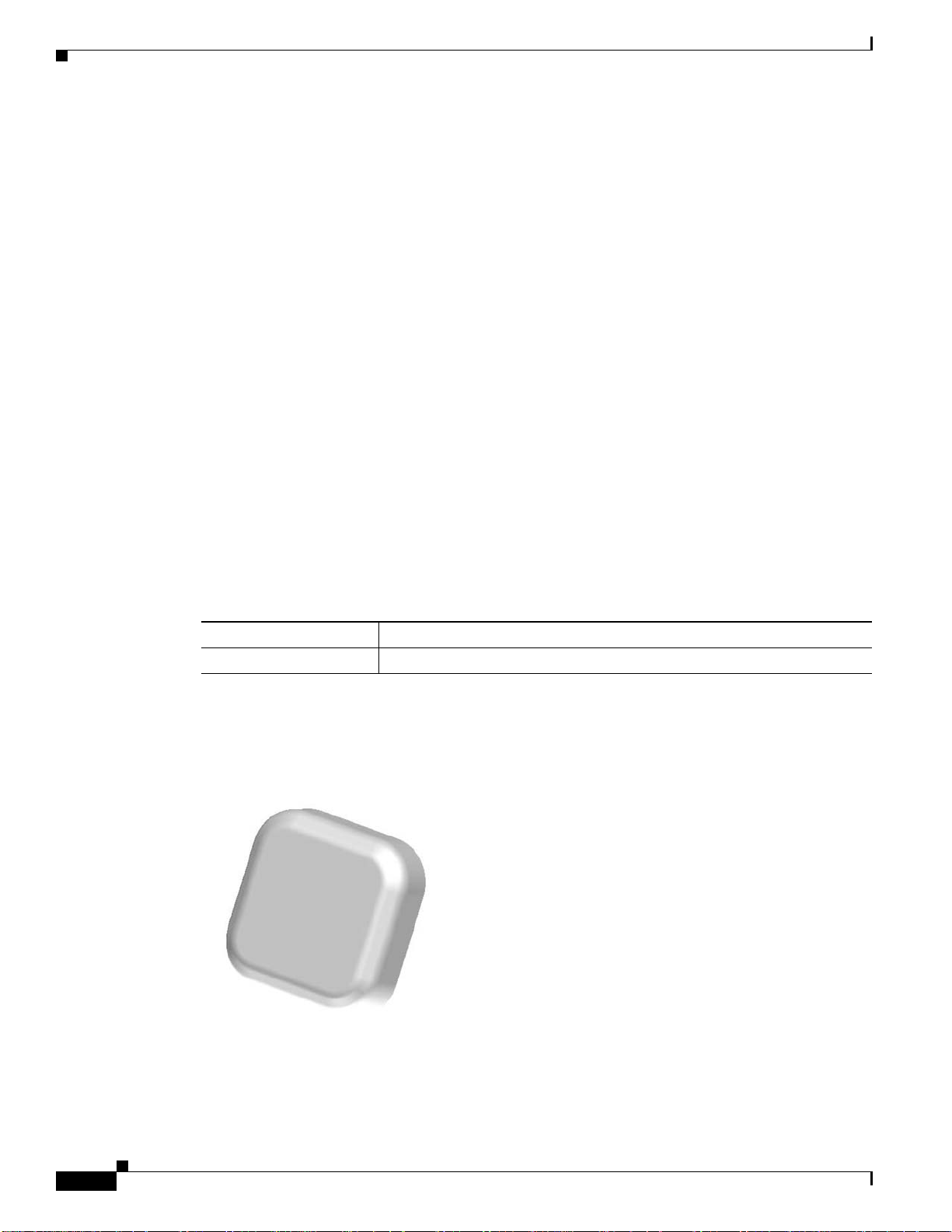
Antenna Assembly
Figure 6-1 Cisco ANT-4G-PNL-OUT-N Antenna
6-2
Cisco CGR 1000 and 2000 Series Connected Grid Antennas Guide
Page 3

Chapter 6 Cisco Multiband Panel Outdoor 4G MIMO Antenna (ANT-4G-PNL-OUT-N)
Technical Specifications
• Radio Frequency Specifications, page 6-3
• Antenna Radiation Patterns, page 6-3
• Environmental Specifications, page 6-17
• Mechanical Specifications, page 6-18
• Power Specifications, page 6-18
Radio Frequency Specifications
Table 6-2 Antenna Radio Frequency Specification
Specification Description
Antenna type 4G directional panel, dual-polarized/MIMO
Frequency
Nominal impedance 50 ohms
VSWR 2.0:1 Maximum
Gain The gain values (dBi) for each frequency range
Technical Specifications
• 698 to 960MHz
• 1710 to 2700 MHz
are:
3 dB beamwidth (vertical plane)
3 dB beamwidth (horizontal plane)
F/B ratio
Isolation
Polarization Slant +/- 45 degrees
Radiation Pattern Directional
Antenna Radiation Patterns
• 698 to 960 MHz—8.0 to 10.0 dBi
• 1710 to 2170 MHz—6.0 to 8.5 dBi
• 2200 to 2400 MHz—6.5 to 9.5 dBi
• 2500 to 2700 MHz—8.5 to 9.5 dBi
• 55 to 70 degrees—698 to 960 MHz
• 53 to 98 degrees—1710 to 2200 MHz
• 60 to 70 degrees—2200 to 2500 MHz
• 55 to 70 degrees—2500 to 2700 MHz
• 55 to 70 degrees—698 to 960 MHz
• 50 to 90 degrees—1710 to 2200 MHz
• > 15 dB, typical 20 dB—698 to 960 MHz
• > 17 dB, typical 23 dB—1700 to 2700 MHz
• > 30 dB
• 698 MHz Antenna Radiation Pattern, page 6-4
Cisco CGR 1000 and 2000 Series Connected Grid Antennas Guide
6-3
Page 4

Chapter 6 Cisco Multiband Panel Outdoor 4G MIMO Antenna (ANT-4G-PNL-OUT-N)
30
25
20
15
10
5
0
5
10
0
30
60
90
120
150
180
210
240
270
300
330
349220
Technical Specifications
• 880 MHz Antenna Radiation Pattern, page 6-6
• 960 MHz Antenna Radiation Pattern, page 6-8
• 1710 MHz Antenna Radiation Pattern, page 6-10
• 1950 MHz Antenna Radiation Pattern, page 6-12
• 2170 MHz Antenna Radiation Pattern, page 6-14
• 2700 MHz Antenna Radiation Pattern, page 6-16
698 MHz Antenna Radiation Pattern
• 698 MHz Antenna Radiation Pattern—Horizontal Plane, page 6-4
• 698 MHz Antenna Radiation Pattern—Vertical Plane, page 6-5
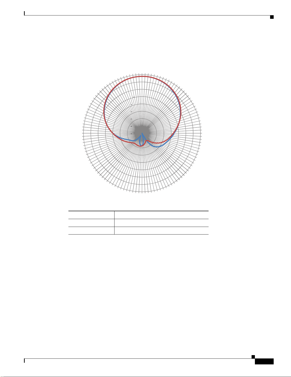
698 MHz Antenna Radiation Pattern—Horizontal Plane
Figure 6-2 698 MHz Antenna Radiation Pattern—Horizontal Plane
6-4
Line Color Description
Blue (
—)Port 1
Red (
—)Port 2
Cisco CGR 1000 and 2000 Series Connected Grid Antennas Guide
Page 5
Chapter 6 Cisco Multiband Panel Outdoor 4G MIMO Antenna (ANT-4G-PNL-OUT-N)
698 MHz Antenna Radiation Pattern—Vertical Plane
Figure 6-3 698 MHz Antenna Radiation Pattern—Vertical Plane
0
10
330
5
0
5
300
10
15
20
25
270
30
Technical Specifications
30
60
90
240
210
Line Color Description
Blue (
—)Port 1
Red (
—)Port 2
180
120
150
349221
Cisco CGR 1000 and 2000 Series Connected Grid Antennas Guide
6-5
Page 6

Chapter 6 Cisco Multiband Panel Outdoor 4G MIMO Antenna (ANT-4G-PNL-OUT-N)
30
25
20
15
10
5
0
5
10
0
30
60
90
120
150
180
210
240
270
300
330
349222
Technical Specifications
880 MHz Antenna Radiation Pattern
• 880MHz Antenna Radiation Pattern—Horizontal Plane, page 6-6
• 880MHz Antenna Radiation Pattern—Vertical Plane, page 6-7
880MHz Antenna Radiation Pattern—Horizontal Plane
Figure 6-4 880 MHz Antenna Radiation Pattern—Horizontal Plane
6-6
Line Color Description
Blue (
—)Port 1
Red (
—)Port 2
Cisco CGR 1000 and 2000 Series Connected Grid Antennas Guide
Page 7

Chapter 6 Cisco Multiband Panel Outdoor 4G MIMO Antenna (ANT-4G-PNL-OUT-N)
30
25
20
15
10
5
0
5
10
0
30
60
90
120
150
180
210
240
270
300
330
349223
880MHz Antenna Radiation Pattern—Vertical Plane
Figure 6-5 880 MHz Antenna Radiation Pattern—Vertical Plane
Technical Specifications
Line Color Description
Blue (
—)Port 1
Red (
—)Port 2
Cisco CGR 1000 and 2000 Series Connected Grid Antennas Guide
6-7
Page 8

Chapter 6 Cisco Multiband Panel Outdoor 4G MIMO Antenna (ANT-4G-PNL-OUT-N)
30
25
20
15
10
5
0
5
10
0
30
60
90
120
150
180
210
240
270
300
330
349224
Technical Specifications
960 MHz Antenna Radiation Pattern
• 960 MHz Antenna Radiation Pattern—Horizontal Plane, page 6-8
• 960 MHz Antenna Radiation Pattern—Vertical Plane, page 6-9
960 MHz Antenna Radiation Pattern—Horizontal Plane
Figure 6-6 960 MHz Antenna Radiation Pattern—Horizontal Plane
6-8
Line Color Description
Blue (
—)Port 1
Red (
—)Port 2
Cisco CGR 1000 and 2000 Series Connected Grid Antennas Guide
Page 9

Chapter 6 Cisco Multiband Panel Outdoor 4G MIMO Antenna (ANT-4G-PNL-OUT-N)
30
25
20
15
10
5
0
5
10
0
30
60
90
120
150
180
210
240
270
300
330
349225
960 MHz Antenna Radiation Pattern—Vertical Plane
Figure 6-7 960 MHz Antenna Radiation Pattern—Vertical Plane
Technical Specifications
Line Color Description
Blue (
—)Port 1
Red (
—)Port 2
Cisco CGR 1000 and 2000 Series Connected Grid Antennas Guide
6-9
Page 10

Chapter 6 Cisco Multiband Panel Outdoor 4G MIMO Antenna (ANT-4G-PNL-OUT-N)
30
25
20
15
10
5
0
5
10
0
30
60
90
120
150
180
210
240
270
300
330
349226
Technical Specifications
1710 MHz Antenna Radiation Pattern
• 1710 MHz Antenna Radiation Pattern—Horizontal Plane, page 6-10
• 1710 MHz Antenna Radiation Pattern—Vertical Plane, page 6-11
1710 MHz Antenna Radiation Pattern—Horizontal Plane
Figure 6-8 1710 MHz Antenna Radiation Pattern—Horizontal Plane
6-10
Line Color Description
Blue (
—)Port 1
Red (
—)Port 2
Cisco CGR 1000 and 2000 Series Connected Grid Antennas Guide
Page 11

Chapter 6 Cisco Multiband Panel Outdoor 4G MIMO Antenna (ANT-4G-PNL-OUT-N)
1710 MHz Antenna Radiation Pattern—Vertical Plane
Figure 6-9 1710 MHz Antenna Radiation Pattern—Vertical Plane
0
10
330
5
0
5
300
10
15
20
25
270
30
Technical Specifications
30
60
90
240
210
Line Color Description
Blue (
—)Port 1
Red (
—)Port 2
180
120
150
349227
Cisco CGR 1000 and 2000 Series Connected Grid Antennas Guide
6-11
Page 12

Chapter 6 Cisco Multiband Panel Outdoor 4G MIMO Antenna (ANT-4G-PNL-OUT-N)
Technical Specifications
1950 MHz Antenna Radiation Pattern
• 1950 MHz Antenna Radiation Pattern—Horizontal Plane, page 6-12
• 1950 MHz Antenna Radiation Pattern—Vertical Plane, page 6-13
1950 MHz Antenna Radiation Pattern—Horizontal Plane
Figure 6-10 1950 MHz Antenna Radiation Pattern—Horizontal Plane
330
300
270
10
5
0
5
10
15
20
25
30
0
30
60
90
240
210
Line Color Description
Blue (
—)Port 1
Red (
—)Port 2
180
120
150
349228
6-12
Cisco CGR 1000 and 2000 Series Connected Grid Antennas Guide
Page 13

Chapter 6 Cisco Multiband Panel Outdoor 4G MIMO Antenna (ANT-4G-PNL-OUT-N)
1950 MHz Antenna Radiation Pattern—Vertical Plane
Figure 6-11 1950 MHz Antenna Radiation Pattern—Vertical Plane
0
10
330
5
0
5
300
10
15
20
25
270
30
Technical Specifications
30
60
90
240
210
Line Color Description
Blue (
—)Port 1
Red (
—)Port 2
180
120
150
349229
Cisco CGR 1000 and 2000 Series Connected Grid Antennas Guide
6-13
Page 14

Chapter 6 Cisco Multiband Panel Outdoor 4G MIMO Antenna (ANT-4G-PNL-OUT-N)
30
25
20
15
10
5
0
5
10
0
30
60
90
120
150
180
210
240
270
300
330
349230
Technical Specifications
2170 MHz Antenna Radiation Pattern
• 2170 MHz Antenna Radiation Pattern—Horizontal Plane, page 6-14
• 2170 MHz Antenna Radiation Pattern—Vertical Plane, page 6-15
2170 MHz Antenna Radiation Pattern—Horizontal Plane
Figure 6-12 2170 MHz Antenna Radiation Pattern—Horizontal Plane
6-14
Line Color Description
Blue (
—)Port 1
Red (
—)Port 2
Cisco CGR 1000 and 2000 Series Connected Grid Antennas Guide
Page 15

Chapter 6 Cisco Multiband Panel Outdoor 4G MIMO Antenna (ANT-4G-PNL-OUT-N)
2170 MHz Antenna Radiation Pattern—Vertical Plane
Figure 6-13 2170 MHz Antenna Radiation Pattern—Vertical Plane
0
10
330
5
0
5
300
10
15
20
25
270
30
Technical Specifications
30
60
90
240
210
Line Color Description
Blue (
—)Port 1
Red (
—)Port 2
180
120
150
349231
Cisco CGR 1000 and 2000 Series Connected Grid Antennas Guide
6-15
Page 16

Chapter 6 Cisco Multiband Panel Outdoor 4G MIMO Antenna (ANT-4G-PNL-OUT-N)
Technical Specifications
2700 MHz Antenna Radiation Pattern
• 2700 MHz Antenna Radiation Pattern—Horizontal Plane, page 6-16
• 2700 MHz Antenna Radiation Pattern—Vertical Plane, page 6-17
2700 MHz Antenna Radiation Pattern—Horizontal Plane
Figure 6-14 2700 MHz Antenna Radiation Pattern—Horizontal Plane
330
300
270
10
5
0
5
10
15
20
25
30
0
30
60
90
240
210
Line Color Description
Blue (
—)Port 1
Red (
—)Port 2
180
120
150
349232
6-16
Cisco CGR 1000 and 2000 Series Connected Grid Antennas Guide
Page 17

Chapter 6 Cisco Multiband Panel Outdoor 4G MIMO Antenna (ANT-4G-PNL-OUT-N)
2700 MHz Antenna Radiation Pattern—Vertical Plane
Figure 6-15 2700 MHz Antenna Radiation Pattern—Vertical Plane
0
10
330
5
0
5
300
10
15
20
25
270
30
Technical Specifications
30
60
90
240
210
Line Color Description
Blue (
—)Port 1
Red (
—)Port 2
Environmental Specifications
Table 6-3 Environmental Specifications for the Cisco ANT-4G-PNL-OUT-N Antenna
Specification Description
Operating temperature range -40 to 158°F (-40 to 70°C)
Storage temperature range -40 to 185°F (-40 to +85°C)
180
120
150
349233
Cisco CGR 1000 and 2000 Series Connected Grid Antennas Guide
6-17
Page 18
Installing the Antenna
Mechanical Specifications
Table 6-4 Mechanical Specifications for the Cisco ANT-4G-PNL-OUT-N Antenna
Specification Description
Mount style Wall or mast mount
Location Indoor or outdoor
Connector Dual type N female direct connect
Dimensions (width x length x height) 11.61 x 11.61 x 3.23 in. (29.5 x 29.5 x 82 cm)
Weight 3.22 lbs (1.46 kg)
Wind rating 160 km/hr (93 mph)
IP rating IP55
Radome Polycarbonate, UV resistant, white
Material substance compliance ROHS compliant
Chapter 6 Cisco Multiband Panel Outdoor 4G MIMO Antenna (ANT-4G-PNL-OUT-N)
Power Specifications
Table 6-5 Power Specifications for the Cisco ANT-4G-PNL-OUT-N Antenna
Specification Description
Maximum Voltage 2.0:1
Nominal Impedance 50 ohms
Maximum input power per port 10 watts
Installing the Antenna
The antenna installation includes the following procedures:
• Contents of the Antenna Kit, page 6-19
• Safety Warnings, page 6-19
• Safety Precautions, page 6-20
• Tools and Equipment Required, page 6-21
• Preparing the Antenna for Installation, page 6-21
• Mounting the Antenna, page 6-21
• Connecting the Lightning Arrestor, page 6-22
• Connecting the Antenna to the Router, page 6-22
6-18
Cisco CGR 1000 and 2000 Series Connected Grid Antennas Guide
Page 19

Chapter 6 Cisco Multiband Panel Outdoor 4G MIMO Antenna (ANT-4G-PNL-OUT-N)
Contents of the Antenna Kit
The antenna kit contains:
• 1 x Cisco ANT-4G-PNL-OUT-N antenna
• 1 x mounting bracket
Safety Warnings
Installing the Antenna
Warning
Warning
Warning
Warning
Warning
A void using or servicing any equipment that has outdoor connections during an electrical storm.
There may be a risk of electric shock from lightning.
Do not work on the system, or connect or disconnect cables, during periods of lightning activity.
Statement 1001
Do not locate the outdoor antenna near overhead power lines or other electric light or power
circuits, or where it can come into contact with such circuits. When installing the antenna, take
extreme care not to come into contact with such circuits, as they may cause serious injury or
death. For proper installation and grounding of the antenna, please refer to national and local
codes (for example, U.S.:NFPA 70, National Electrical Code, Article 810, Canada:Canadian
Electrical Code, Section 54).
This equipment must be grounded. Never defeat the ground conductor or operate the equipment
in the absence of a suitably installed ground conductor. Contact the appropriate electrical
inspection authority or an electrician if you are uncertain that suitable grounding is available.
Statement 1024
Only trained and qualified personnel should be allowed to install, replace, or service this
equipment.
Statement 1030
Statement 1052
Statement 1088
Warning
Warning
To report a gas leak, do not use a telephone in the vicinity of the leak.
This warning symbol means danger. Yo u ar e in a situation that could cause bodily injury. Before
you work on any equipment, be aware of the hazards involved with electrical circuitry and be
familiar with standard practices for preventing accidents. Use the statement number provided at
the end of each warning to locate its translation in the translated safety warnings that
accompanied this device.
Statement 1071.
Cisco CGR 1000 and 2000 Series Connected Grid Antennas Guide
SAVE THESE INSTRUCTIONS.
Statement 1039
6-19
Page 20

Installing the Antenna
Chapter 6 Cisco Multiband Panel Outdoor 4G MIMO Antenna (ANT-4G-PNL-OUT-N)
Warning
This product is not intended to be directly connected to the Cable Distribution System.
Additional regulatory compliance and legal requirements may apply for direct connection to the
Cable Distribution System. This product may connect to the Cable Distribution System ONLY
through a device that is approved for direct connection.
Safety Precautions
Warning
Installation of this antenna near power lines is dangerous. For your safety , follow the installation
directions.
Each year hundreds of people are killed or injured when attempting to install an antenna. In many of
these cases, the victim was aware of the danger of electrocution, but did not take adequate steps to avoid
the hazard.
For your safety, and to help you achieve a good installation, please read and follow these safety
precautions. They may save your life!
For your safety, read and follow these safety precautions.
• If you are installing an antenna for the first time, for your own safety as well as others, seek
professional assistance. Your Cisco sales representative can explain which mounting method to use
for the size and type antenna you are about to install.
• Before you install an antenna, contact your Cisco account representative to explain which mounting
method to use for the size and type of antenna that you are about to install.
• Find someone to help you—installing an antenna is often a two-person job.
• Select your installation site with safety, as well as performance, in mind. Remember that electric
power lines and phone lines look alike. For your safety, assume that any overhead line can kill you.
Statement 1078
6-20
• Contact your electric power company. Tell them your plans and ask them to come look at your
proposed installation.
• Plan your installation carefully and completely before you begin. Each person involved in an
in stallat i on shoul d be assig ned to a sp ecifi c task, an d should k n ow wh a t to do and when to do it. One
person should be in charge of the operation to issue instructions and watch for signs of trouble.
• When installing your antenna, follow these guidelines:
–
Do not use a metal ladder.
–
Do not work on a wet or windy day.
–
Do dress properly—wear shoes with rubber soles and heels, rubber gloves, and a long-sleeved
shirt or jacket.
• If the assembly starts to drop, move away from it and let it fall. Because the antenna, mast, cable,
and metal guy wires are all excellent conductors of electrical current, even the slightest touch of any
of these parts to a power line completes an electrical path through the antenna and the installer.
• If any part of the antenna system should come in contact with a power line, do not touch it or try to
remove it yourself. Call your local power company to have it removed safely.
• If an accident should occur with the power lines, call for qualified emergency help immediately.
Cisco CGR 1000 and 2000 Series Connected Grid Antennas Guide
Page 21

Chapter 6 Cisco Multiband Panel Outdoor 4G MIMO Antenna (ANT-4G-PNL-OUT-N)
Tools and Equipment Required
In addition to the parts included in the antenna kit described in the section Contents of the Antenna Kit,
page 6-19, you must provide the following tool to install the antenna on the router:
• Phillips screwdriver
• Open-ended wrench
• Electric drill
Note This list does not include the tools and equipment required to assemble and erect the tower, mast, or other
structure you intend to mount your antenna on.
Preparing the Antenna for Installation
Installing the Antenna
Note Before mounting the antenna on a mast or wall:
- the antenna must be attached to the mounting bracket.
- the signal cable must be attached to the antenna.
To prepare the antenna for installation:
Step 1 Attach the antenna to the mounting bracket.
Step 2 To attach the signal cable to the antenna:
a. Loosely hand-tighten the antenna nut so that the cable can be attached with ease.
b. Attach the cable to the antenna.
c. Hand tighten the N-connector to the antenna.
d. Tighten the antenna nut securely after the cable is installed.
e. Use weatherproof sealing tape (coax seal) at the connector junction. Start wrapping at the top of the
antenna connector, wrap downward 3 times and end about 2 inches downward from the center of the
connector junction. Then wrap upwards another 3 times to reach the top of the antenna connector.
Step 3 Decide if the antenna is to be mounted on a wall or mast. Perform the following steps where relevant:
a. If the antenna is going to be mast mounted, install the clamps provided in the mounting bracket.
Align the antenna so the top of the metal bracket is even with or slightly above the top of the mast
tubing.
b. If the antenna is to be wall mounted, use the screws provided.
c. Use both clamps and screws for extra security if required.
Mounting the Antenna
Follow these instructions to mount the antenna:
Cisco CGR 1000 and 2000 Series Connected Grid Antennas Guide
6-21
Page 22
Chapter 6 Cisco Multiband Panel Outdoor 4G MIMO Antenna (ANT-4G-PNL-OUT-N)
Obtaining Documentation and Submitting a Service Request
Step 1 Mark the desired location where you plan to mount the antenna and create a hole to receive the antenna.
Note The rubber washer is not required for ceiling tile installations.
Step 2 Make sure that the antenna is properly positioned, then tighten the washer and plastic nut to secure the
antenna.
Connecting the Lightning Arrestor
To install a lightning-protection device, seeCisco Lightning Arrestors, page 1-36 in Chapter 1, “Cisco
CGR 1000 and 2000 Series Connected Grid Antennas Overview”.
Connecting the Antenna to the Router
To attach the router-end of the cable to your router, see Connecting the Antenna to the CGR 1120,
page 1-33 in Chapter 1, “Cisco CGR 1000 and 2000 Series Connected Grid Antennas Overview”.
Note Coaxial cable loses efficiency as the frequency increases, resulting in signal loss. The cable should be
kept as short as possible because cable length also determines the amount of signal loss—the longer the
cable length or run, the greater the loss).
Obtaining Documentation and Submitting a Service Request
For information on obtaining documentation, submitting a service request, and gathering additional
information, see the monthly What’s New in Cisco Product Documentation, which also lists all new and
revised Cisco technical documentation, at:
http://www.cisco.com/en/US/docs/general/whatsnew/whatsnew.html
Subscribe to the What’s New in Cisco Product Documentation as an RSS (Really Simple Syndication)
feed, and set it so content is delivered directly to your desktop using a reader application. The RSS feeds
are a free service and Cisco currently supports RSS Version 2.0.
Cisco and the Cisco Logo are trademarks of Cisco Systems, Inc. and/or its affiliates in the U.S. and other countries. A listing of Cisco's trademarks
can be found at www.cisco.com/go/trademarks. Third party trademarks mentioned are the property of their respective owners. The use of the word
partner does not imply a partnership relationship between Cisco and any other company. (1005R)
6-22
Cisco CGR 1000 and 2000 Series Connected Grid Antennas Guide
 Loading...