

Cisco 7010, 7120, 7115, 7125, AMP7150 Installation Manual
...
Firepower 7000 and 8000 Series Installation Guide
Vers ion 6. 0
November 5, 2015
Cisco Systems, Inc.
www.cisco.com
Cisco has more than 200 offices worldwide.
Addresses, phone numbers, and fax numbers
are listed on the Cisco website at
www.cisco.com/go/offices.

THE SPECIFICATIONS AND INFORMATION REGARDING THE PRODUCTS IN THIS MANUAL ARE SUBJECT TO CHANGE WITHOUT NOTICE. ALL
STATEMENTS, INFORMATION, AND RECOMMENDATIONS IN THIS MANUAL ARE BELIEVED TO BE ACCURATE BUT ARE PRESENTED WITHOUT
WARRANTY OF ANY KIND, EXPRESS OR IMPLIED. USERS MUST TAKE FULL RESPONSIBILITY FOR THEIR APPLICATION OF ANY PRODUCTS.
THE SOFTWARE LICENSE AND LIMITED WARRANTY FOR THE ACCOMPANYING PRODUCT ARE SET FORTH IN THE INFORMATION PACKET THAT
SHIPPED WITH THE PRODUCT AND ARE INCORPORATED HEREIN BY THIS REFERENCE. IF YOU ARE UNABLE TO LOCATE THE SOFTWARE LICENSE
OR LIMITED WARRANTY, CONTACT YOUR CISCO REPRESENTATIVE FOR A COPY.
The Cisco implementation of TCP header compression is an adaptation of a program developed by the University of California, Berkeley (UCB) as part of UCB’s public
domain version of the UNIX operating system. All rights reserved. Copyright © 1981, Regents of the University of California.
NOTWITHSTANDING ANY OTHER WARRANTY HEREIN, ALL DOCUMENT FILES AND SOFTWARE OF THESE SUPPLIERS ARE PROVIDED “AS IS” WITH
ALL FAULTS. CISCO AND THE ABOVE-NAMED SUPPLIERS DISCLAIM ALL WARRANTIES, EXPRESSED OR IMPLIED, INCLUDING, WITHOUT
LIMITATION, THOSE OF MERCHANTABILITY, FITNESS FOR A PARTICULAR PURPOSE AND NONINFRINGEMENT OR ARISING FROM A COURSE OF
DEALING, USAGE, OR TRADE PRACTICE.
IN NO EVENT SHALL CISCO OR ITS SUPPLIERS BE LIABLE FOR ANY INDIRECT, SPECIAL, CONSEQUENTIAL, OR INCIDENTAL DAMAGES, INCLUDING,
WITHOUT LIMITATION, LOST PROFITS OR LOSS OR DAMAGE TO DATA ARISING OUT OF THE USE OR INABILITY TO USE THIS MANUAL, EVEN IF CISCO
OR ITS SUPPLIERS HAVE BEEN ADVISED OF THE POSSIBILITY OF SUCH DAMAGES.
Cisco and the Cisco logo are trademarks or registered trademarks of Cisco and/or its affiliates in the U.S. and other countries. To view a list of Cisco trademarks, go to this
URL: www.cisco.com/go/trademarks. Third-party trademarks mentioned are the property of their respective owners. The use of the word partner does not imply a partnership
relationship between Cisco and any other company. (1721R)
Any Internet Protocol (IP) addresses and phone numbers used in this document are not intended to be actual addresses and phone numbers. Any examples, command display
output, network topology diagrams, and other figures included in the document are shown for illustrative purposes only. Any use of actual IP addresses or phone numbers in
illustrative content is unintentional and coincidental.
© 2015 Cisco Systems, Inc. All rights reserved.

Introduction to the Firepower System 1-1
Firepower System Appliances 1-2
7000 and 8000 Series Appliances 1-3
Virtual Appliances 1-3
Cisco ASA with FirePOWER Services 1-3
Appliances Delivered with Version 6.0 1-4
Supported Capabilities by Firepower Management Center Model 1-5
Supported Capabilities by Managed Device Model 1-7
7000 and 8000 Series Device Chassis Designations 1-8
CONTENTS
Firepower System Components 1-9
Licensing the Firepower System 1-11
Security, Internet Access, and Communication Ports 1-13
Internet Access Requirements 1-13
Communication Ports Requirements 1-14
Preconfiguring Appliances 1-16
Deploying on a Management Network 2-1
Management Deployment Considerations 2-1
Understanding Management Interfaces 2-2
Single Management Interface 2-2
Multiple Management Interfaces 2-2
Deployment Options 2-3
Deploying with Traffic Channels 2-3
Deploying with Network Routes 2-4
Security Considerations 2-5
Special Case: Connecting 8000 Series Devices 2-5
Deploying Firepower Managed Devices 3-1
Sensing Deployment Considerations 3-1
Understanding Sensing Interfaces 3-2
Passive Interfaces 3-2
Inline Interfaces 3-2
Switched Interfaces 3-3
Firepower 7000 and 8000 Series Installation Guide
1

Contents
Routed Interfaces 3-3
Hybrid Interfaces 3-4
Connecting Devices to Your Network 3-4
Using a Hub 3-4
Using a Span Port 3-5
Using a Network Tap 3-5
Cabling Inline Deployments on Copper Interfaces 3-5
Special Case: Connecting Firepower 8000 Series Devices 3-6
Deployment Options 3-7
Deploying with a Virtual Switch 3-7
Deploying with a Virtual Router 3-8
Deploying with Hybrid Interfaces 3-9
Deploying a Gateway VPN 3-10
Deploying with Policy-Based NAT 3-11
Deploying with Access Control 3-11
Using Multiple Sensing Interfaces on a Managed Device 3-16
Complex Network Deployments 3-18
Integrating with VPNs 3-18
Detecting Intrusions on Other Points of Entry 3-19
Deploying in Multi-Site Environments 3-20
Integrating Multiple Management Interfaces within a Complex Network 3-22
Integrating Managed Devices within Complex Networks 3-23
Installing a Firepower Managed Device 4-1
Included Items 4-1
Security Considerations 4-1
Identifying the Management Interfaces 4-2
Firepower 7000 Series 4-2
Firepower 8000 Series 4-2
Identifying the Sensing Interfaces 4-3
Firepower 7000 Series 4-3
Firepower 8000 Series 4-7
Using Devices in a Stacked Configuration 4-13
Connecting the Firepower 8140 4-14
Connecting the Firepower 82xx Family and Firepower and AMP 83xx Family 4-15
Using the 8000 Series Stacking Cable 4-18
Managing Stacked Devices 4-19
Rack-Mounting a Firepower Device 4-20
Redirecting Console Output 4-22
Firepower 7000 and 8000 Series Installation Guide
2

Using the Shell 4-22
Using the Web Interface 4-23
Testing an Inline Bypass Interface Installation 4-24
Setting Up Firepower Managed Devices 5-1
Understanding the Setup Process 5-2
Beginning the Setup 5-2
Performing Initial Setup on a Firepower Device Using the CLI 5-3
Registering a Firepower Device to a Management Center Using the CLI 5-4
Initial Setup Page: Firepower Devices 5-5
Next Steps 5-9
Using the LCD Panel on a Firepower Device 6-1
Understanding LCD Panel Components 6-2
Using the LCD Multi-Function Keys 6-3
Contents
Idle Display Mode 6-4
Network Configuration Mode 6-4
Allowing Network Reconfiguration Using the LCD Panel 6-6
System Status Mode 6-7
Information Mode 6-8
Error Alert Mode 6-9
Hardware Specifications 7-1
Rack and Cabinet Mounting Options 7-1
Firepower 7000 Series Devices 7-1
Firepower 7010, 7020, 7030, and 7050 7-1
Firepower 7110 and 7120 7-6
Firepower 7115, 7125, and AMP7150 7-13
Firepower 8000 Series Devices 7-21
Firepower 8000 Series Chassis Front View 7-22
Firepower 8000 Series Chassis Rear View 7-26
Firepower 8000 Series Physical and Environmental Parameters 7-29
Firepower 8000 Series Modules 7-32
Restoring a Firepower System Appliance to Factory Defaults 8-1
Before You Begin 8-1
Configuration and Event Backup Guidelines 8-1
Traffic Flow During the Restore Process 8-1
Understanding the Restore Process 8-2
Firepower 7000 and 8000 Series Installation Guide
3

Contents
Obtaining the Restore ISO and Update Files 8-3
Beginning the Restore Process 8-4
Starting the Restore Utility Using KVM or Physical Serial Port 8-4
Starting the Restore Utility Using Lights-Out Management 8-5
Using the Interactive Menu to Restore an Appliance 8-6
Identifying the Appliance’s Management Interface 8-8
Specifying ISO Image Location and Transport Method 8-8
Updating System Software and Intrusion Rules During Restore 8-10
Downloading the ISO and Update Files and Mounting the Image 8-10
Invoking the Restore Process 8-11
Saving and Loading Restore Configurations 8-13
Next Steps 8-14
Setting Up Lights-Out Management 8-14
Enabling LOM and LOM Users 8-16
Installing an IPMI Utility 8-17
Power Requirements for Firepower Devices A-1
Warnings and Cautions A-1
Static Control A-1
Firepower 70xx Family Appliances A-1
Installation A-2
Grounding/Earthing Requirements A-2
Firepower 71xx Family Appliances A-3
Installation A-4
Grounding/Earthing Requirements A-5
Firepower 81xx Family Appliances A-5
AC Installation A-6
DC Installation A-7
Grounding/Earthing Requirements A-8
Firepower 82xx Family Appliances A-9
AC Installation A-10
DC Installation A-11
Grounding/Earthing Requirements A-12
Firepower and AMP 83xx Family Appliances A-13
AC Installation A-14
DC Installation A-15
Grounding/Earthing Requirements A-16
Firepower 7000 and 8000 Series Installation Guide
4

Using SFP Transceivers in 3D71x5
and AMP7150 Devices
3D71x5 and AMP7150 SFP Sockets and Transceivers B-1
Inserting an SFP Transceiver B-2
To insert an SFP transceiver: B-2
Removing an SFP Transceiver B-3
Inserting and Removing Firepower 8000 Series Modules C-1
Module Slots on the Firepower 8000 Series Devices C-1
Firepower 81xx Family C-1
Firepower 82xx Family and 83xx Family C-2
Included Items C-2
Identifying the Module Parts C-3
Before You Begin C-4
Removing a Module or Slot Cover C-5
B-1
Contents
Inserting a Module or Slot Cover C-6
Scrubbing the Hard Drive D-1
Scrubbing the Contents of the Hard Drive D-1
Preconfiguring Firepower Managed Devices E-1
Before You Begin E-1
Required Preconfiguration Information E-1
Optional Preconfiguration Information E-2
Preconfiguring Time Management E-2
Installing the System E-3
Registering a Device E-3
Preparing the Appliance for Shipment E-4
Deleting Devices from a Management Center E-4
Deleting a License from a Management Center E-5
Powering Down the Appliance E-5
Shipping Considerations E-5
Troubleshooting the Appliance Preconfiguration E-6
Firepower 7000 and 8000 Series Installation Guide
5

Contents
Firepower 7000 and 8000 Series Installation Guide
6

CHA PT ER
1
Introduction to the Firepower System
The Cisco Firepower System combines the security of an industry-leading network intrusion protection
system with the power to control access to your network based on detected applications, users, and
URLs. You can also use Firepower System appliances to serve in a switched, routed, or hybrid (switched
and routed) environment; to perform network address translation (NAT); and to build secure virtual
private network (VPN) tunnels between the virtual routers of Firepower managed devices.
The Cisco Firepower Management Center provides a centralized management console and database
repository for the Firepower System. Managed devices installed on network segments monitor traffic for
analysis.
Devices in a passive deployment monitor traffic flowing across a network, for example, using a switch
SPAN, virtual switch, or mirror port. Passive sensing interfaces receive all traffic unconditionally and no
traffic received on these interfaces is retransmitted.
Devices in an inline deployment allow you to protect your network from attacks that might affect the
availability, integrity, or confidentiality of hosts on the network. Inline interfaces receive all traffic
unconditionally, and traffic received on these interfaces is retransmitted unless explicitly dropped by
some configuration in your deployment. Inline devices can be deployed as a simple intrusion prevention
system. You can also configure inline devices to perform access control as well as manage network
traffic in other ways.
This installation guide provides information about deploying, installing, and setting up Firepower
System appliances (devices and Management Centers). It also contains hardware specifications and
safety and regulatory information for Firepower System appliances.
Tip You can host virtual Firepower Management Centers and devices, which can manage and be managed
by physical appliances. However, virtual appliances do not support any of the system’s hardware-based
features: redundancy, switching, routing, and so on. See the Firepower NGIPSv for VMware Quick Start
Guide for more information.
The topics that follow introduce you to the Firepower System and describe its key components:
• Firepower System Appliances, page 1-2
• Firepower System Components, page 1-9
• Licensing the Firepower System, page 1-11
• Security, Internet Access, and Communication Ports, page 1-13
• Preconfiguring Appliances, page 1-16
Firepower 7000 and 8000 Series Installation Guide
1-1

Firepower System Appliances
Firepower System Appliances
A Firepower System appliance is either a traffic-sensing managed device or a managing Firepower
Management Center:
Physical devices are fault-tolerant, purpose-built network appliances available with a range of
throughputs and capabilities. Firepower Management Centers serve as central management points for
these devices, and automatically aggregate and correlate the events they generate. There are several
models of each physical appliance type; these models are further grouped into series and family. Many
Firepower System capabilities are appliance dependent.
Firepower Management Centers
A Firepower Management Center provides a centralized management point and event database for your
Firepower System deployment. Firepower Management Centers aggregate and correlate intrusion, file,
malware, discovery, connection, and performance data, assessing the impact of events on particular hosts
and tagging hosts with indications of compromise. This allows you to monitor the information that your
devices report in relation to one another, and to assess and control the overall activity that occurs on your
network.
Key features of the Firepower Management Center include:
• device, license, and policy management
• display of event and contextual information using tables, graphs, and charts
Chapter 1 Introduction to the Firepower System
• health and performance monitoring
• external notification and alerting
• correlation, indications of compromise, and remediation features for real-time threat response
• custom and template-based reporting
Managed Devices
Devices deployed on network segments within your organization monitor traffic for analysis. Devices
deployed passively help you gain insight into your network traffic. Deployed inline, you can use
Firepower devices to affect the flow of traffic based on multiple criteria. Depending on model and
license, devices:
• gather detailed information about your organization’s hosts, operating systems, applications, users,
files, networks, and vulnerabilities
• block or allow network traffic based on various network-based criteria, as well as other criteria
including applications, users, URLs, IP address reputations, and the results of intrusion or malware
inspections
• have switching, routing, DHCP, NAT, and VPN capabilities, as well as configurable bypass
interfaces, fast-path rules, and strict TCP enforcement
• have high availability (redundancy) to help you ensure continuity of operations, and stacking to
combine resources from multiple devices
Yo u must manage Firepower devices with a Firepower Management Center.
1-2
Appliance Types
The Firepower System can run on fault-tolerant, purpose-built physical network appliances available
from Cisco. There are several models of each Firepower Management Center and managed device; these
models are further grouped into series and family.
Firepower 7000 and 8000 Series Installation Guide

Chapter 1 Introduction to the Firepower System
Physical managed devices come in a range of throughputs and have a range of capabilities. Physical
Firepower Management Centers also have a range of device management, event storage, and host and
user monitoring capabilities.
You can also deploy 64-bit virtual Firepower Management Centers and virtual Firepower managed
devices as ESXi hosts using the VMware vSphere Hypervisor or vCloud Director environment.
Either type of Management Center (physical or virtual) can manage any type of device: physical, virtual,
and Cisco ASA with FirePOWER Services. Note, however, that many Firepower System capabilities are
appliance dependent.
For more information on Firepower System appliances, including the features and capabilities they
support, see:
• 7000 and 8000 Series Appliances, page 1-3
• Virtual Appliances, page 1-3
• Cisco ASA with FirePOWER Services, page 1-3
• Appliances Delivered with Version 6.0, page 1-4
• Supported Capabilities by Firepower Management Center Model, page 1-5
• Supported Capabilities by Managed Device Model, page 1-7
Firepower System Appliances
7000 and 8000 Series Appliances
The 7000 and 8000 Series are Firepower physical appliances. Firepower 8000 Series devices are more
powerful and support a few features that Firepower 7000 Series devices do not. For detailed information
on 7000 and 8000 Series appliances, see the Firepower 7000 and 8000 Series Installation Guide.
Virtual Appliances
You can deploy 64-bit virtual Firepower Management Center and managed devices as ESXi hosts using
the VMware vSphere Hypervisor or vCloud Director environments.
Regardless of the licenses installed and applied, virtual appliances do not support any of the system’s
hardware-based features: redundancy and resource sharing, switching, routing, and so on. Also, virtual
devices do not have web interfaces. For detailed information on virtual appliances, see the Firepower
NGIPSv for VMware Quick Start Guide.
Cisco ASA with FirePOWER Services
Cisco ASA with FirePOWER Services (ASA FirePOWER devices) functions similarly to a managed
device. In this deployment, the ASA device provides the first-line system policy and passes traffic to the
Firepower System for access control, intrusion detection and prevention, discovery, and advanced
malware protection. See the Version 6.0 Firepower System Appliances table for a list of supported ASA
models.
Regardless of the licenses installed and applied, ASA FirePOWER devices do not support any of the
following Firepower System features:
Firepower 7000 and 8000 Series Installation Guide
1-3

Firepower System Appliances
• ASA FirePOWER devices do not support the Firepower System’s hardware-based features: high
• You cannot use the Firepower Management Center web interface to configure ASA FirePOWER
• You cannot use the Firepower Management Center to shut down, restart, or otherwise manage
ASA FirePOWER devices have a software and command line interface (CLI) unique to the ASA
platform. You use these ASA-specific tools to install the system and to perform other platform-specific
administrative tasks.
Note If you edit an ASA FirePOWER device and switch from multiple context mode to single context mode
(or visa versa), the device renames all of its interfaces. You must reconfigure all Firepower System
security zones, correlation rules, and related configurations to use the updated ASA FirePOWER
interface names.
Chapter 1 Introduction to the Firepower System
availability, stacking, switching, routing, VPN, NAT, and so on. However, the ASA platform does
provide these features, which you can configure using the ASA CLI and ASDM. See the ASA
documentation for more information.
interfaces. The Firepower Management Center does not display ASA interfaces when the
ASA FirePOWER device is deployed in SPAN port mode.
ASA FirePOWER processes.
Appliances Delivered with Version 6.0
The following table lists the appliances that Cisco delivers with Version 6.0 of the Firepower System.
Table 1-1 Version 6.0 Firepower System Appliances
Models/Family Firepower Series Form Type
70xx Family:
• 7010, 7020, 7030, 7050
71xx Family:
• 7110, 7120
• 7115, 7125
• AMP7150
80xx Family:
• AMP8050
81xx Family:
• 8120, 8130, 8140
• AMP8150
82xx Family:
• 8250
7000 Series hardware device
7000 Series hardware device
8000 Series hardware device
8000 Series hardware device
8000 Series hardware device
1-4
• 8260, 8270, 8290
Firepower 7000 and 8000 Series Installation Guide

Chapter 1 Introduction to the Firepower System
Table 1-1 Version 6.0 Firepower System Appliances (continued)
Models/Family Firepower Series Form Type
83xx Family:
• 8350
• 8360, 8370, 8390
• AMP8350
• AMP8360, AMP8370, AMP8390
64-bit virtual NGIPSv n/a software device
ASA FirePOWER:
• ASA5585-X-SSP-10,
ASA5585-X-SSP-20,
ASA5585-X-SSP-40,
ASA5585-X-SSP-60
ASA FirePOWER:
• ASA5506-X ASA5506H-X, 5506W-X,
5508-X, ASA5512-X, ASA5515-X,
ASA5518-X, ASA5525-X,
ASA5545-X, ASA5555-X
Firepower Management Centers:
• MC750, MC1500, MC2000, MC3500,
MC2000, MC4000
64-bit Firepower Management Center
Virtual
Firepower System Appliances
8000 Series hardware device
n/a hardware device
n/a software device
n/a hardware Management
Center
n/a software Management
Center
Note that reimaging results in the loss of all configuration and event data on the appliance. See Restoring
a Firepower System Appliance to Factory Defaults, page 8-1 for more information.
Tip You can migrate specific configuration and event data from a Version 4.10.3 deployment to a Version 5.2
deployment. Then, you can update through a series of procedures to Version 6.0. For more information,
see the Firepower System Migration Guide for Version 5.2.
Supported Capabilities by Firepower Management Center Model
When running Version 6.0, all Firepower Management Centers have similar capabilities, with only a few
model-based restrictions. The following table matches the major capabilities of the system with the
Firepower Management Centers that support those capabilities, assuming you are managing devices that
support those features and have the correct licenses installed and applied.
In addition to the capabilities listed in the table, Firepower Management Center models vary in terms of
how many devices they can manage, how many events they can store, and how many hosts and users they
can monitor. For more information, see the Firepower Management Center Configuration Guide.
Also, keep in mind that although you can use any model of Firepower Management Center running
Version 6.0 of the system to manage any Version 6.0 device, many system capabilities are limited by the
device model. For more information, see Supported Capabilities by Managed Device Model, page 1-7.
Firepower 7000 and 8000 Series Installation Guide
1-5

Chapter 1 Introduction to the Firepower System
Firepower System Appliances
Table 1-2 Supported Capabilities by Firepower Management Center Model
Management Center
Feature or Capability Management Center
collect discovery data (host, application, and user) reported by managed
yes yes
devices and build a network map for your organization
view geolocation data for your network traffic yes yes
manage an intrusion detection and prevention (IPS) deployment yes yes
manage devices performing Security Intelligence filtering yes yes
manage devices performing simple network-based control, including
yes yes
geolocation-based filtering
manage devices performing application control yes yes
manage devices performing user control yes yes
manage devices that filter network traffic by literal URL yes yes
manage devices performing URL Filtering by category and reputation yes yes
manage devices performing simple file control by file type yes yes
manage devices performing network-based advanced malware protection
yes yes
(AMP)
receive endpoint-based malware (FireAMP) events from your FireAMP
yes yes
deployment
manage device-based hardware-based features:
• fast-path rules
yes yes
Virtual
• strict TCP enforcement
• configurable bypass interfaces
• tap mode
• switching and routing
• NAT policies
• VPN
manage device-based redundancy and resource sharing:
• device stacks
• device high availability
• stacks in high-availability pairs
yes yes
separate and manage internal and external traffic using traffic channels yes yes
isolate and manage traffic on different networks using multiple management
yes yes
interfaces
install a malware storage pack yes no
connect to an eStreamer, host input, or database client yes yes
1-6
Firepower 7000 and 8000 Series Installation Guide

Chapter 1 Introduction to the Firepower System
Supported Capabilities by Managed Device Model
Devices are the appliances that handle network traffic; therefore, many Firepower System capabilities
are dependent on the model of your managed devices.
The following table matches the major capabilities of the system with the devices that support those
capabilities, assuming you have the correct licenses installed and applied from the managing Firepower
Management Center.
Keep in mind that although you can use any model of Firepower Management Center running Version
6.0 of the system to manage any Version 6.0 device, a few system capabilities are limited by the
Firepower Management Center model. For more information, see Supported Capabilities by Firepower
Management Center Model, page 1-5.
Table 1-3 Supported Capabilities by Managed Device Model
Firepower System Appliances
7000 and 8000 Series
Feature or Capability
network discovery: host, application, and user yes yes yes
intrusion detection and prevention (IPS) yes yes yes
Security Intelligence filtering yes yes yes
access control: basic network control yes yes yes
access control: geolocation-based filtering yes yes yes
access control: application control yes yes yes
access control: user control yes yes yes
access control: literal URLs yes yes yes
access control: URL Filtering by category and reputation yes yes yes
file control: by file type yes yes yes
network-based advanced malware protection (AMP) yes yes yes
Automatic Application Bypass yes no yes
fast-path rules 8000 Series no no
strict TCP enforcement yes no no
configurable bypass interfaces except where hardware
tap mode yes no no
switching and routing yes no no
NAT policies yes no no
VPN yes no no
device stacking 8140
device high availability yes no no
stacks in high-availability pairs 8140
Device ASA FirePOWER
no no
limited
no no
82xx Family
83xx Family
no no
82xx Family
83xx Family
Virtual
Device
Firepower 7000 and 8000 Series Installation Guide
1-7

Firepower System Appliances
Table 1-3 Supported Capabilities by Managed Device Model (continued)
Chapter 1 Introduction to the Firepower System
7000 and 8000 Series
Feature or Capability
traffic channels yes no no
multiple management interfaces yes no no
malware storage pack yes no no
restricted command line interface (CLI) yes yes yes
external authentication yes no no
connect to an eStreamer client yes yes no
Device ASA FirePOWER
Virtual
Device
7000 and 8000 Series Device Chassis Designations
The following section lists the 7000 Series and 8000 Series devices and their respective chassis hardware
codes. The chassis code appears on the regulatory label on the outside of the chassis, and is the official
reference code for hardware certifications and safety.
7000 Series Chassis Designations
The following table lists the chassis designations for the 7000 Series models available world-wide.
Table 1-4 7000 Series Chassis Models
Firepower and AMP Device
Model Hardware Chassis Code
7010, 7020, 7030 CHRY-1U-AC
7050 NEME-1U-AC
7110, 7120 (Copper) GERY-1U-8-C-AC
7110, 7120 (Fiber) GERY-1U-8-FM-AC
7115, 7125, AMP7150 GERY-1U-4C8S-AC
8000 Series Chassis Designations
The following table lists the chassis designations for the 7000 and 8000 Series models available
world-wide.
Table 1-5 8000 Series Chassis Models
Firepower and AMP Device Model Hardware Chassis Code
AMP8050 (AC or DC power) CHAS-1U-AC/DC
8120, 8130, 8140, AMP8150
(AC or DC power)
8250, 8260, 8270, 8290
(AC or DC power)
CHAS-1U-AC/DC
CHAS-2U-AC/DC
1-8
Firepower 7000 and 8000 Series Installation Guide

Chapter 1 Introduction to the Firepower System
Table 1-5 8000 Series Chassis Models (continued)
Firepower and AMP Device Model Hardware Chassis Code
8350, 8360, 8370, 8390
(AC or DC power)
AMP830, AMP8360, AMP8370, AMP8390
(AC or DC power)
Firepower System Components
The sections that follow describe some of the key capabilities of the Firepower System that contribute
to your organization’s security, acceptable use policy, and traffic management strategy.
Tip Many Firepower System capabilities are appliance model, license, and user role dependent. Where
needed, Firepower System documentation outlines the requirements for each feature and task.
Firepower System Components
PG35-2U-AC/DC
PG35-2U-AC/DC
Redundancy and Resource Sharing
The redundancy and resource-sharing features of the Firepower System allow you to ensure continuity
of operations and to combine the processing resources of multiple physical devices:
• Device stacking allows you to increase the amount of traffic inspected on a network segment by
connecting two to four physical devices in a stacked configuration.
• Device high availability allows you to establish redundancy of networking functionality and
configuration data between two or more 7000 and 8000 Series devices or stacks.
Multiple Management Interfaces
You can use multiple management interfaces on a Firepower Management Center, device, or both, to
improve performance by separating traffic into two traffic channels: the management traffic channel
carries inter-device communication and the event traffic channel carries high volume event traffic such
as intrusion events. Both traffic channels can be carried on the same management interface or split
between two management interfaces, each interface carrying one traffic channel.
You can also create a route from a specific management interface on your Firepower Management Center
to a different network, allowing your Firepower Management Center to isolate and manage device traffic
on one network separately from device traffic on another network.
Additional management interfaces have many of the same capabilities as the default management
interface with the following exceptions:
• You can configure DHCP on the default (eth0) management interface only. Additional (eth1 and so
on) interfaces require unique static IP addresses and hostnames.
• You must configure both traffic channels to use the same non-default management interface when
your Firepower Management Center and managed device are separated by a NAT device.
• You can use Lights-Out Management on the default management interface only.
• On the 70xx Family, you can separate traffic into two channels and configure those channels to send
traffic to one or more management interfaces on the Firepower Management Center. However,
because the 70xx Family contains only one management interface, the device receives traffic sent
from the Firepower Management Center on only one management interface.
Firepower 7000 and 8000 Series Installation Guide
1-9

Firepower System Components
After your appliance is installed, use the web browser to configure multiple management interfaces. See
Multiple Management Interfaces in the Firepower Management Center Configuration Guide for more
information.
Network Traffic Management
The Firepower System’s network traffic management features allow 7000 and 8000 Series devices to act
as part of your organization’s network infrastructure. You can:
• configure a Layer 2 deployment to perform packet switching between two or more network
segments
• configure a Layer 3 deployment to route traffic between two or more interfaces
• perform network address translation (NAT)
• build secure VPN tunnels from virtual routers on managed devices to remote devices or other
third-party VPN endpoints
Discovery and Identity
Cisco’s discovery and identity technology collects information about hosts, operating systems,
applications, users, files, networks, geolocation information, and vulnerabilities, in order to provide you
with a complete view of your network.
You can use the Firepower Management Center’s web interface to view and analyze data collected by
the system. You can also use discovery and identity to help you perform access control and modify
intrusion rule states.
Chapter 1 Introduction to the Firepower System
Access Control
Access control is a policy-based feature that allows you to specify, inspect, and log the traffic that
traverses your network. As part of access control, the Security Intelligence feature allows you to
blacklist—deny traffic to and from—specific IP addresses before the traffic is subjected to deeper
analysis.
After Security Intelligence filtering occurs, you can define which and how traffic is handled by targeted
devices, from simple IP address matching to complex scenarios involving different users, applications,
ports, and URLs. You can trust, monitor, or block traffic, or perform further analysis, such as:
• intrusion detection and prevention
• file control
• file tracking and network-based advanced malware protection (AMP)
Intrusion Detection and Prevention
Intrusion detection and prevention is a policy-based feature, integrated into access control, that allows
you to monitor your network traffic for security violations and, in inline deployments, to block or alter
malicious traffic. An intrusion policy contains a variety of components, including:
• rules that inspect the protocol header values, payload content, and certain packet size characteristics
• rule state configuration based on FireSIGHT recommendations
• advanced settings, such as preprocessors and other detection and performance features
• preprocessor rules that allow you to generate events for associated preprocessors and preprocessor
options
1-10
Firepower 7000 and 8000 Series Installation Guide

Chapter 1 Introduction to the Firepower System
File Tracking, Control, and Network-Based Advanced Malware Protection (AMP)
To help you identify and mitigate the effects of malware, the Firepower System’s file control, network
file trajectory, and advanced malware protection components can detect, track, capture, analyze, and
optionally block the transmission of files (including malware files) in network traffic.
File control is a policy-based feature, integrated into access control, that allows managed devices to
detect and block your users from uploading (sending) or downloading (receiving) files of specific types
over specific application protocols.
Network-based advanced malware protection (AMP) allows the system to inspect network traffic for
malware in several types of files. Appliances can store detected files for further analysis, either to their
hard drive or (for some models) a malware storage pack.
Regardless of whether you store a detected file, you can submit it to the Cisco cloud for a simple
known-disposition lookup using the files SHA-256 hash value. You can also submit files for dynamic
analysis, which produces a threat score. Using this contextual information, you can configure the system
to block or allow specific files.
FireAMP is Cisco’s enterprise-class, advanced malware analysis and protection solution that discovers,
understands, and blocks advanced malware outbreaks, advanced persistent threats, and targeted attacks.
If your organization has a FireAMP subscription, individual users install FireAMP Connectors on their
computers and mobile devices (also called endpoints). These lightweight agents communicate with the
Cisco cloud, which in turn communicates with the Firepower Management Center.
After you configure the Firepower Management Center to connect to the cloud, you can use the
Firepower Management Center web interface to view endpoint-based malware events generated as a
result of scans, detections, and quarantines on the endpoints in your organization. The Firepower
Management Center also uses FireAMP data to generate and track indications of compromise on hosts,
as well as display network file trajectories.
Licensing the Firepower System
The network file trajectory feature allows you to track a file’s transmission path across a network. The
system uses SHA-256 hash values to track files. Each file has an associated trajectory map, which
contains a visual display of the file’s transfers over time as well as additional information about the file.
Application Programming Interfaces
There are several ways to interact with the system using application programming interfaces (APIs):
• The Event Streamer (eStreamer) allows you to stream several kinds of event data from a Firepower
System appliance to a custom-developed client application.
• The database access feature allows you to query several database tables on a Firepower Management
Center, using a third-party client that supports JDBC SSL connections.
• The host input feature allows you to augment the information in the network map by importing data
from third-party sources using scripts or command-line files.
• Remediations are programs that your Firepower Management Center can automatically launch when
certain conditions on your network are met. This can not only automatically mitigate attacks when
you are not immediately available to address them, but can also ensure that your system remains
compliant with your organization’s security policy.
Licensing the Firepower System
You can license a variety of features to create an optimal Firepower System deployment for your
organization. You use the Firepower Management Center to manage licenses for itself and the devices it
manages. The license types offered by the Firepower System depend upon the type of device you want
to manage:
Firepower 7000 and 8000 Series Installation Guide
1-11

Licensing the Firepower System
• For Firepower, ASA FirePOWER, and NGIPSv devices, you must use Classic Licenses.
By default, your Firepower Management Center can perform domain control, host, application, and user
discovery, as well as decrypting and inspecting SSL- and TLS-encrypted traffic.
Feature-specific classic licenses allow your managed devices to perform a variety of functions including:
• intrusion detection and prevention
• Security Intelligence filtering
• file control and AMP for Firepower
• application, user, and URL control
• switching and routing
• device high availability
• network address translation (NAT)
• virtual private network (VPN) deployments
There are a few ways you may lose access to licensed features in the Firepower System. You can remove
licenses from the Firepower Management Center, which affects all of its managed devices. You can also
disable licensed capabilities on specific managed devices. Finally, some licenses may expire. Though
there are some exceptions, you cannot use the features associated with an expired or deleted license.
The following summarizes Firepower System Classic Licenses:
Chapter 1 Introduction to the Firepower System
Protection
A Protection license allows managed devices to perform intrusion detection and prevention, file
control, and Security Intelligence filtering.
Control
A Control license allows managed devices to perform user and application control, switching and
routing (including DHCP relay), and NAT. It also allows configuring devices and stacks into
high-availability pairs. A Control license requires a Protection license.
URL Filtering
A URL Filtering license allows managed devices to use regularly updated cloud-based category and
reputation data to determine which traffic can traverse your network, based on the URLs requested
by monitored hosts. A URL Filtering license requires a Protection license.
Malware
A Malware license allows managed devices to perform network-based advanced malware protection
(AMP), that is, to detect and block malware in files transmitted over your network. It also allows
you to view trajectories, which track files transmitted over your network. A Malware license
requires a Protection license.
VPN
A VPN license allows you to build secure VPN tunnels among the virtual routers on Cisco managed
devices, or from managed devices to remote devices or other third-party VPN endpoints. A VPN
license requires Protection and Control licenses.
See the Firepower Management Center Configuration Guide for complete information about classic
license types and restrictions.
1-12
Firepower 7000 and 8000 Series Installation Guide

Chapter 1 Introduction to the Firepower System
Security, Internet Access, and Communication Ports
Security, Internet Access, and Communication Ports
To safeguard the Firepower Management Center, you should install it on a protected internal network.
Although the Firepower Management Center is configured to have only the necessary services and ports
available, you must make sure that attacks cannot reach it (or any managed devices) from outside the
firewall.
If the Firepower Management Center and its managed devices reside on the same network, you can
connect the management interfaces on the devices to the same protected internal network as the
Firepower Management Center. This allows you to securely control the devices from the Firepower
Management Center. You can also configure multiple management interfaces to allow the Firepower
Management Center to manage and isolate traffic from devices on other networks.
Regardless of how you deploy your appliances, intra-appliance communication is encrypted. However,
you must still take steps to ensure that communications between appliances cannot be interrupted,
blocked, or tampered with; for example, with a distributed denial of service (DDoS) or
man-in-the-middle attack.
Also note that specific features of the Firepower System require an Internet connection. By default, all
appliances are configured to directly connect to the Internet. Additionally, the system requires certain
ports remain open for basic intra-appliance communication, for secure appliance access, and so that
specific system features can access the local or Internet resources they need to operate correctly.
Tip With the exception of Cisco ASA with FirePOWER Services, Firepower System appliances support the
use of a proxy server. For more information, see the Firepower Management Center Configuration
Guide.
For more information, see:
• Internet Access Requirements, page 1-13
• Communication Ports Requirements, page 1-14
Internet Access Requirements
Firepower System appliances are configured to directly connect to the Internet on ports 443/tcp (HTTPS)
and 80/tcp (HTTP), which are open by default; see Communication Ports Requirements, page 1-14. Note
that most Firepower System appliances support use of a proxy server; see the Configuring Network
Settings chapter in the Firepower Management Center Configuration Guide. Note also that a proxy
server cannot be used for whois access.
The following table describes the Internet access requirements of specific features of the Firepower
System.
Table 1-6 Firepower System Feature Internet Access Requirements
Feature Internet access is required to... Appliances
dynamic analysis: querying query the Collective Security Intelligence
Cloud for threat scores of files previously
submitted for dynamic analysis.
dynamic analysis: submitting submit files to the Collective Security
Intelligence Cloud for dynamic analysis.
Management Center
Managed devices
Firepower 7000 and 8000 Series Installation Guide
1-13

Chapter 1 Introduction to the Firepower System
Security, Internet Access, and Communication Ports
Table 1-6 Firepower System Feature Internet Access Requirements (continued)
Feature Internet access is required to... Appliances
FireAMP integration receive endpoint-based (FireAMP) malware
events from the Collective Security Intelligence
Cloud cloud.
intrusion rule, VDB, and GeoDB
updates
download or schedule the download of a
intrusion rule, GeoDB, or VDB update directly
to an appliance.
network-based AMP perform malware cloud lookups. Management Center
RSS feed dashboard widget download RSS feed data from an external
source, including Cisco.
Security Intelligence filtering download Security Intelligence feed data from
an external source, including the Firepower
System Intelligence Feed.
system software updates download or schedule the download of a system
update directly to an appliance.
URL Filtering download cloud-based URL category and
reputation data for access control, and perform
lookups for uncategorized URLs.
whois request whois information for an external host. Any except virtual devices and
Management Center
Management Center
Any except virtual devices and
ASA FirePOWER
Management Center
Any except virtual devices and
ASA FirePOWER
Management Center
ASA FirePOWER
Communication Ports Requirements
Firepower System appliances communicate using a two-way, SSL-encrypted communication channel,
which by default uses port 8305/tcp. The system requires this port remain open for basic intra-appliance
communication. Other open ports allow:
• access to an appliance’s web interface
• secure remote connections to an appliance
• certain features of the system to access the local or Internet resources they need to function correctly
In general, feature-related ports remain closed until you enable or configure the associated feature. For
example, until you connect the Firepower Management Center to a User Agent, the agent
communications port (3306/tcp) remains closed. As another example, port 623/udp remains closed on
7000 and 8000 Series appliances until you enable LOM.
Caution Do not close an open port until you understand how this action will affect your deployment.
For example, closing port 25/tcp (SMTP) outbound on a managed device blocks the device from sending
email notifications for individual intrusion events (see the Firepower Management Center Configuration
Guide). As another example, you can disable access to a physical managed device’s web interface by
closing port 443/tcp (HTTPS), but this also prevents the device from submitting suspected malware files
to the cloud for dynamic analysis.
1-14
Firepower 7000 and 8000 Series Installation Guide

Chapter 1 Introduction to the Firepower System
Security, Internet Access, and Communication Ports
Note that the system allows you to change some of its communication ports:
• You can specify custom ports for LDAP and RADIUS authentication when you configure a
connection between the system and the authentication server; see the Firepower Management
Center Configuration Guide.
• You can change the management port (8305/tcp); see the Firepower Management Center
Configuration Guide. However, Cisco strongly recommends that you keep the default setting. If you
change the management port, you must change it for all appliances in your deployment that need to
communicate with each other.
• You can use port 32137/tcp to allow upgraded Firepower Management Centers to communicate with
the Collective Security Intelligence Cloud. However, Cisco recommends you switch to port 443,
which is the default for fresh installations of Version 6.0 and later. For more information, see the
Firepower Management Center Configuration Guide.
The following table lists the open ports required by each appliance type so that you can take full
advantage of Firepower System features.
Table 1-7 Default Communication Ports for Firepower System Features and Operations
Port Description Direction Is Open on... To...
22/tcp SSH/SSL Bidirectional Any allow a secure remote connection to the
appliance.
25/tcp SMTP Outbound Any send email notices and alerts from the
appliance.
53/tcp DNS Outbound Any use DNS.
67/udp
68/udp
80/tcp HTTP Outbound Any except virtual
DHCP Outbound Any use DHCP.
Note These ports are closed by default.
allow the RSS Feed dashboard widget to
devices and
connect to a remote web server.
ASA FirePOWER
Bidirectional Management Center update custom and third-party Security
Intelligence feeds via HTTP.
download URL category and reputation data
(port 443 also required).
161/udp SNMP Bidirectional Any except virtual
devices and
allow access to an appliance’s MIBs via
SNMP polling.
ASA FirePOWER
162/udp SNMP Outbound Any send SNMP alerts to a remote trap server.
389/tcp
636/tcp
389/tcp
LDAP Outbound Any except virtual
devices
communicate with an LDAP server for
external authentication.
LDAP Outbound Management Center obtain metadata for detected LDAP users.
636/tcp
443/tcp HTTPS Inbound Any except virtual
access an appliance’s web interface.
devices and
ASA FirePOWER
Firepower 7000 and 8000 Series Installation Guide
1-15

Chapter 1 Introduction to the Firepower System
Preconfiguring Appliances
Table 1-7 Default Communication Ports for Firepower System Features and Operations (continued)
Port Description Direction Is Open on... To...
443/tcp HTTPS
Bidirectional Management Center obtain:
AMQP
cloud comms.
• software, intrusion rule, VDB, and
GeoDB updates
• URL category and reputation data (port
80 also required)
• the Cisco Intelligence feed and other
secure Security Intelligence feeds
• endpoint-based (FireAMP) malware
events
• malware dispositions for files detected in
network traffic
• dynamic analysis information on
submitted files
7000 and 8000 Series
devices
7000 and 8000 Series,
virtual devices, and
download software updates using the device’s
local web interface.
submit files to the Cisco cloud for dynamic
analysis.
ASA FirePOWER
514/udp syslog Outbound Any send alerts to a remote syslog server.
623/udp SOL/LOM Bidirectional 7000 and 8000 Series allow you to perform Lights-Out Management
using a Serial Over LAN (SOL) connection.
1500/tcp
2000/tcp
1812/udp
1813/udp
database
Inbound Management Center allow read-only access to the database by a
access
RADIUS Bidirectional Any except virtual
devices and
ASA FirePOWER
third-party client.
communicate with a RADIUS server for
external authentication and accounting.
3306/tcp User Agent Inbound Management Center communicate with User Agents.
8302/tcp eStreamer Bidirectional Any except virtual
communicate with an eStreamer client.
devices
8305/tcp appliance
comms.
8307/tcp host input
Bidirectional Any securely communicate between appliances in
a deployment. Required.
Bidirectional Management Center communicate with a host input client.
client
32137/tcp cloud comms. Bidirectional Management Center allow upgraded Management Centers to
communicate with the Cisco cloud.
Preconfiguring Appliances
You can preconfigure multiple appliances and Firepower Management Centers in a central location for
later deployment at other sites. For considerations when preconfiguring appliances, see Preconfiguring
Firepower Managed Devices, page E-1.
Firepower 7000 and 8000 Series Installation Guide
1-16

CHA PT ER
2
Deploying on a Management Network
The Firepower System can be deployed to accommodate the needs of each unique network architecture.
The Management Center provides a centralized management console and database repository for the
Firepower System. Devices are installed on network segments to collect traffic connections for analysis.
Management Centers use a management interface to connect to a trusted management network (that is,
a secure internal network not exposed external traffic). Devices connect to a Management Center using
a management interface.
Devices then connect to an external network using sensing interfaces to monitor traffic. For more
information on how to use sensing interfaces in your deployment, see Deploying Firepower Managed
Devices, page 3-1.
Note See the ASA documentation for more information on deployment scenarios for ASA FirePOWER
devices.
Management Deployment Considerations
Your management deployment decisions are based on a variety of factors. Answering these questions
can help you understand your deployment options to configure the most efficient and effective system:
• Will you use the default single management interface to connect your device to your Management
Center? Will you enable additional management interfaces to improve performance, or to isolate
traffic received on the Management Center from different networks? See Understanding
Management Interfaces, page 2-2 for more information.
• Do you want to enable traffic channels to create two connections between the Management Center
and the managed device to improve performance? Do you want to use multiple management
interfaces to further increase throughput capacity between the Management Center and the managed
device? See Deploying with Traffic Channels, page 2-3 for more information.
• Do you want to use one Management Center to manage and isolate traffic from devices on different
networks? See Deploying with Network Routes, page 2-4 for more information.
• Are you deploying your management interfaces in a protected environment? Is appliance access
restricted to specific workstation IP addresses? Security Considerations, page 2-5 describes
considerations for deploying your management interfaces securely.
• Are you deploying 8000 Series devices? See Special Case: Connecting 8000 Series Devices,
page 2-5 for more information.
Firepower 7000 and 8000 Series Installation Guide
2-1
Understanding Management Interfaces
Understanding Management Interfaces
Management interfaces provide the means of communication between the Management Center and all
devices it manages. Maintaining good traffic control between the appliances is essential to the success
of your deployment.
On Management Centers and Firepower devices, you can enable the management interface on the
Management Center, device, or both, to sort traffic between the appliances into two separate traffic
channels. The management traffic channel carries all internal traffic (that is, inter-device traffic specific
to the management of the appliance and the system), and the event traffic channel carries all event traffic
(that is, high volume event traffic, such as intrusion and malware events). Splitting traffic into two
channels creates two connection points between the appliances which increases throughput, thus
improving performance. You can also enable multiple management interfaces to provide still greater
throughput between appliances, or to manage and isolate traffic between devices on different networks.
After you register the device to the Management Center, you can change the default configuration to
enable traffic channels and multiple management interfaces using the web interface on each appliance.
For configuration information, see Configuring Appliance Settings in the Firepower Management
Center Configuration Guide.
Management interfaces are often located on the back of the appliance. See Identifying the Management
Interfaces, page 4-2 for more information.
Chapter 2 Deploying on a Management Network
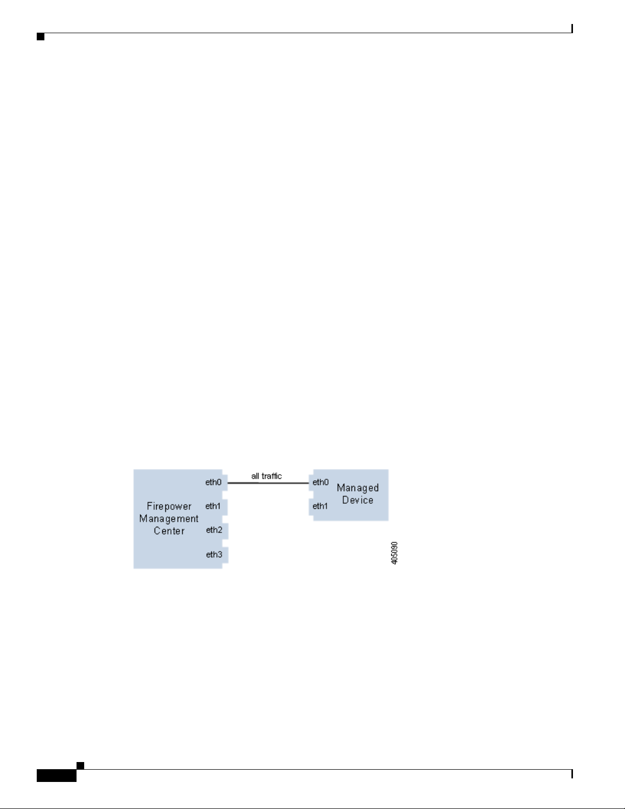
Single Management Interface
When you register your device to a Management Center, you establish a single communication channel
that carries all traffic between the management interface on the Management Center and the management
interface on the device.
The following graphic shows the default single communication channel. One interface carries one
communication channel that contains both management and event traffic.
Multiple Management Interfaces
You can enable and configure multiple management interfaces, each with a specific IPv4 or IPv6 address
and, optionally, a hostname, to provide greater traffic throughput by sending each traffic channel to a
different management interface. Configure a smaller interface to carry the lighter management traffic
load, and a larger interface to carry the heavier event traffic load. You can register devices to separate
management interfaces and configure both traffic channels for the same interface, or use a dedicated
management interface to carry the event traffic channels for all devices managed by the Management
Center.
2-2
Firepower 7000 and 8000 Series Installation Guide
Chapter 2 Deploying on a Management Network
You can also create a route from a specific management interface on your Management Center to a
different network, allowing your Management Center to isolate and manage device traffic on one
network separately from device traffic on another network.
Additional management interfaces function the same as the default management interface with the
following exceptions:
• You can configure DHCP on the default (eth0) management interface only. Additional (eth1 and so
on) interfaces require unique static IP addresses and hostnames. Cisco recommends that you do not
set up DNS entries for additional management interfaces but instead register Management Centers
and devices by IP addresses only for these interfaces.
• You must configure both traffic channels to use the same management interface when you use a
non-default management interface to connect your Management Center and managed device and
those appliances are separated by a NAT device.
• You can use Lights-Out Management on the default management interface only.
• On the 70xx Family, you can separate traffic into two channels and configure those channels to send
traffic to one or more management interfaces on the Management Center. However, because the
70xx Family contains only one management interface, the device receives traffic sent from the
Management Center on only one management interface.
Deployment Options
Deployment Options
You can manage traffic flow using traffic channels to improve performance on your system using one or
more management interfaces. In addition, you can create a route to a different network using a specific
management interface on the Management Center and its managed device, allowing you to isolate traffic
between devices on different networks. For more information, see the following sections:
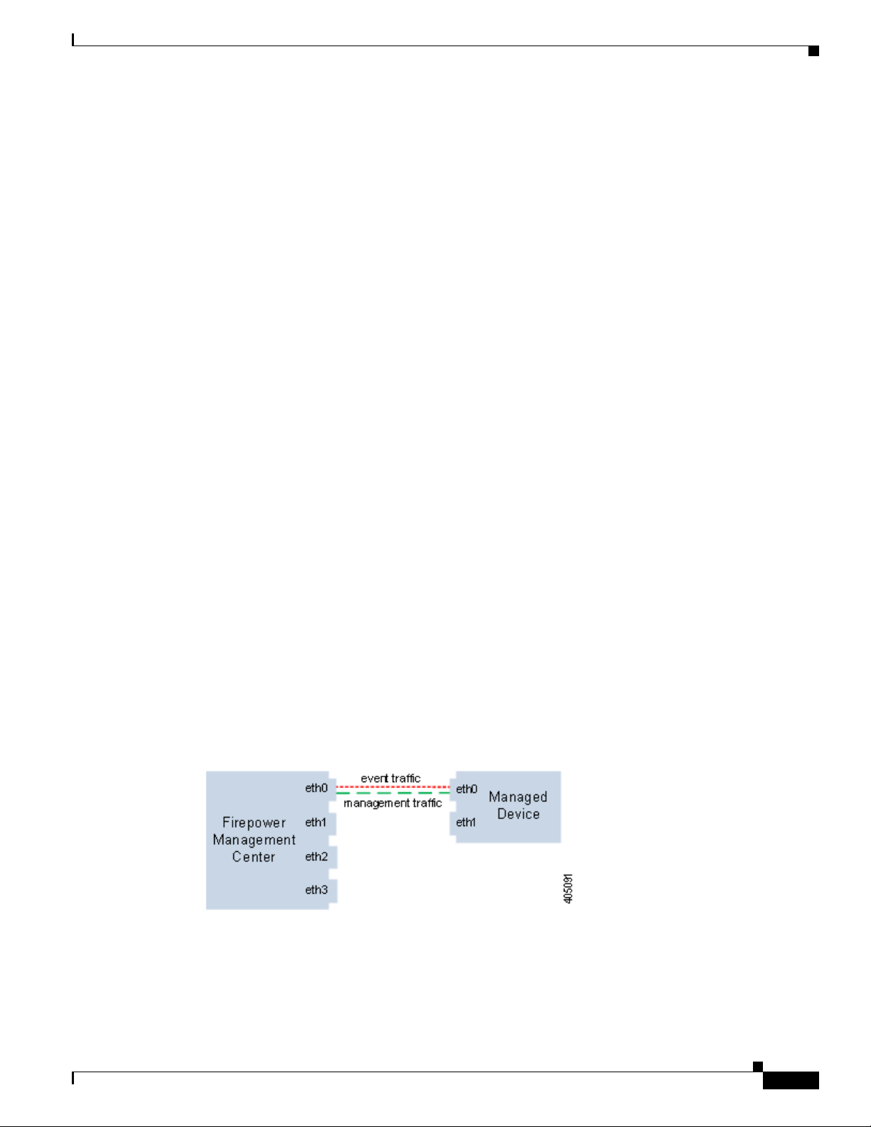
Deploying with Traffic Channels
When you use two traffic channels on one management interface, you create two connections between
the Management Center and the managed device. One channel carries management traffic and one
carries event traffic, separately and on the same interface.
The following example shows the communication channel with two separate traffic channels on the same
interface.
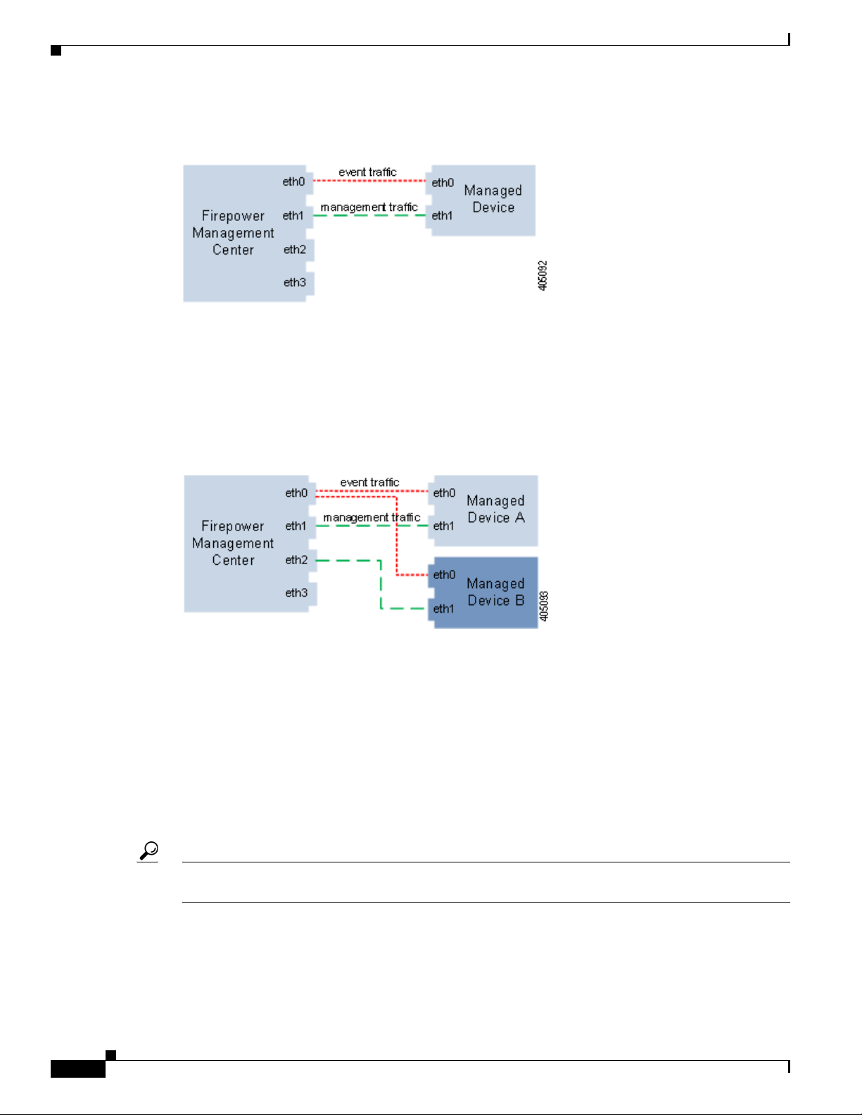
When you use multiple management interfaces, you can improve your performance by dividing the
traffic channels over two management interfaces, thus increasing the traffic flow by adding the capacity
of both interfaces. One interface carries the management traffic channel and the other carries the event
traffic channel. If either interface fails, all traffic reroutes to the active interface and the connection is
maintained.
Firepower 7000 and 8000 Series Installation Guide
2-3
Deploying with Network Routes
The following graphic shows the management traffic channel and the event traffic channel over two
management interfaces.
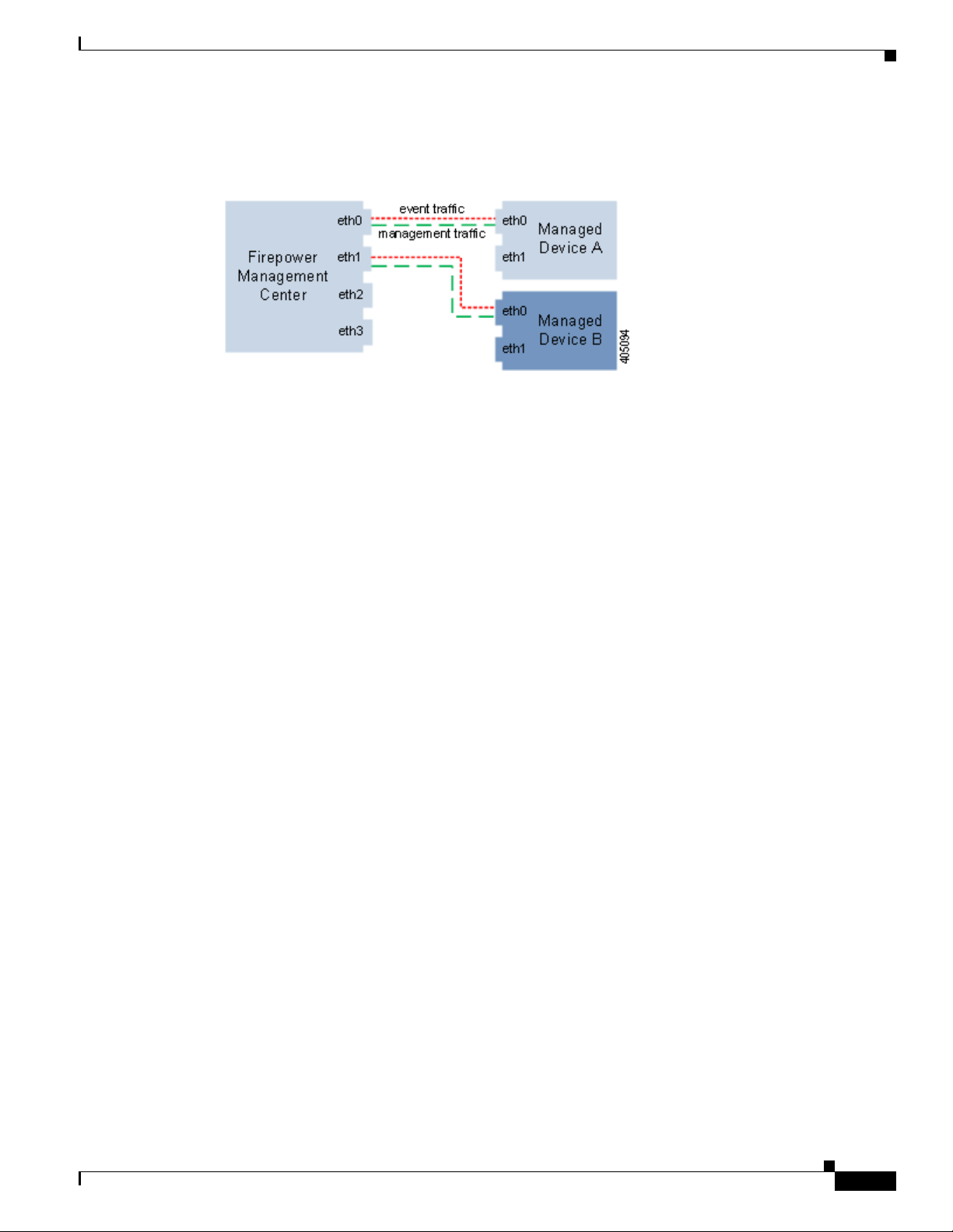
You can use a dedicated management interface to carry only event traffic from multiple devices. In this
configuration, each device is registered to a different management interface to carry the management
traffic channel, and one management interface on the Management Center carries all event traffic
channels from all devices. If an interface fails, traffic reroutes to the active interface and the connection
is maintained. Note that because event traffic for all devices is carried on the same interface, traffic is
not isolated between networks.
The following graphic shows two devices using different management channel traffic interfaces sharing
the same dedicated interface for event traffic channels.
Chapter 2 Deploying on a Management Network
Deploying with Network Routes
You can create a route from a specific management interface on your Management Center to a different
network. When you register a device from that network to the specified management interface on the
Management Center, you provide an isolated connection between the Management Center and the device
on a different network. Configure both traffic channels to use the same management interface to ensure
that traffic from that device remains isolated from device traffic on other networks. Because the routed
interface is isolated from all other interfaces on the Management Center, if the routed management
interface fails, the connection is lost.
Tip You must register a device to the static IP address of any management interface other than the default
(eth0) management interface. DHCP is supported only on the default management interface.
After you install your Management Center, you configure multiple management interfaces using the web
interface. See Configuring Appliance Settings in the Firepower Management Center Configuration
Guide for more information.
Firepower 7000 and 8000 Series Installation Guide
2-4
Chapter 2 Deploying on a Management Network
The following graphic shows two devices isolating network traffic by using separate management
interfaces for all traffic. You can add more management interfaces to configure separate management
and event traffic channel interfaces for each device.
Security Considerations
To deploy your management interfaces in a secure environment, Cisco recommends that you consider
the following:
• Always connect the management interface to a trusted internal management network that is
protected from unauthorized access.
Security Considerations
• Identify the specific workstation IP addresses that can be allowed to access appliances. Restrict
access to the appliance to only those specific hosts using Access Lists within the appliance’s system
policy. For more information, see the Firepower Management Center Configuration Guide.
Special Case: Connecting 8000 Series Devices
Supported Devices: 8000 Series
When you register an 8000 Series device to your Management Center, you must either auto-negotiate on
both sides of the connection, or set both sides to the same static speed to ensure a stable network link.
8000 Series devices do not support half duplex network links; they also do not support differences in
speed or duplex configurations at opposite ends of a connection.
Firepower 7000 and 8000 Series Installation Guide
2-5

Special Case: Connecting 8000 Series Devices
Chapter 2 Deploying on a Management Network
2-6
Firepower 7000 and 8000 Series Installation Guide
 Loading...