

Page 1

Cisco Aironet Wireless L AN Adapters
Hardware Installation Guide
340 and 350 Series
Corporate Headquarters
Cisco Systems, Inc.
170 West Tasman Drive
San Jose, CA 95134-1706
USA
http://www.cisco.com
Tel:
408 526-4000
800 553-NETS (6387)
Fax: 408 526-4100
Customer Order Number:
Text Part Number: OL-0795-01
Page 2

THE SPECIFICATIONS AND INFORMATION REGARDING THE PRODUCTS IN THIS MANUAL ARE SUBJECT TO CHANGE WITHOUT
NOTICE. ALL STATEMENTS, INFORMATION, AND RECOMMENDATIONS IN THIS MANUAL ARE BELIEVED TO BE ACCURA TE BUT
ARE PRESENTED WITHOUT WARRANTY OF ANY KIND, EXPRESS OR IMPLIED. USERS MUST TAKE FULL RESPONSIBILITY FOR
THEIR APPLICATION OF ANY PRODUCTS.
THE SOFTWARE LICENSE AND LIMITED WARRANTY FOR THE ACCOMPANYING PRODUCT ARE SET FORTH IN THE
INFORMATION PACKET THAT SHIPPED WITH THE PRODUCT AND ARE INCORPORATED HEREIN BY THIS REFERENCE. IF YOU
ARE UNABLE TO LOCATE THE SOFTWARE LICENSE OR LIMITED WARRANTY, CONTACT YOUR CISCO REPRESENTATIVE FOR A
COPY.
The following information is for FCC compliance of Class A devices: This equipment has been tested and found to comply with the limits for a Clas s
A digital device, pursuant to part 15 of the FCC rules. These limits are designed to provide reasonable protection against harmful interference when
the equipment is operated in a commercial environment. This equipment generates, uses, and can radiate radio-frequency energy and, if not installed
and used in accordance wi th the instruct ion manua l, m ay cause harmful inte rfe rence to radio co mmunica tion s. Ope ration of t his equipment in a
residential area is likely to cause harmful interference, in which case users will be required to correct the interference at their own expense.
The following infor mation is f or FC C compli ance of Class B devices : The equi pme nt descr ibed i n this ma nual ge nerates a nd ma y radiate
radio-fre que ncy e nergy. If it is not inst all ed i n acco rda nc e wit h C isc o’s installa t ion inst ruc tions , it ma y cau se inte rference with radio and telev ision
reception. This equi pmen t has been tes ted a nd found to comply wit h th e limits for a Class B digital device i n accor dance with the specific ation s in
part 15 of the FCC rules. Thes e specifi cat ions are designed to provi de reason able pr otec tion agai nst su ch interf erenc e in a resid ential installation.
However, there is no guarantee that i nterfere nce wil l not occur in a par ticular i nstal lation.
Modifying the equipme nt witho ut Cisco’s written authori zation ma y resu lt in the equi pment no longer co mplyin g with FCC requirem ent s for C l ass
A or Class B digital devic es. In that ev ent, your r ight t o use the e quipme nt may be limit ed by FCC re gulat ions, and you may be required t o correct
any interference to radi o or televis ion co mmuni cat ions at your own exp ense .
You can determine whether your equipme nt is causi ng interfe rence by turni ng it off. If the in terfere nce s tops, it was proba bly caused by the Cisco
equipment or one of its peri pheral de vices. If the equipment causes interferenc e to radio or televi sion rec eption, try t o correct the interference by
using one or more of the fo llowing measure s:
• Turn the television or radio antenna until t he interf erenc e stops.
• Move the equipment to one si de or the other of the televis ion or ra dio.
• Move the equipment fa rther away fr om th e televisi on or radi o.
• Plug the equipment into an outlet th at is on a different circuit fro m the televi sion or radio. (That is, make cert ain the equipment and the television
or radio are on circuits cont rolled by di fferent c ircuit br eaker s or fuse s.)
Modifications to this product not authori zed by Ci sco Syst ems, Inc . could voi d the FC C app roval and ne gate you r author ity to ope r ate t he produc t .
The Cisco implementation of TCP header compression is an adaptation of a program developed by the University of California, Berkeley (UCB) as
part of UCB’s public domain version of the UNIX operating system. All rights reserved. Copyright © 1981, Regents of the University of California.
NOTWITHSTANDING ANY OTHER WARRANTY HEREIN, ALL DOCUMENT FILES AND SOFTWARE OF THESE SUPPLIERS ARE
PROVIDED “A S I S” WITH AL L FAULTS. CISCO AND TH E A BOV E-N A MED S UPP LI ER S DISC L AIM AL L WARRANTIES , E XPR ESS ED
OR IMPLIED, INCLUDING, WITHOUT LIMITATION, THOSE OF MERCHANTABILITY, FITNESS FOR A PARTICULAR PURPOSE AND
NONINFRING E M E N T OR A R I S IN G F R OM A COU R S E OF DEALIN G, USAGE, OR TRADE P R A C T IC E .
IN NO EVENT SHALL CISCO OR ITS SUPPLIERS BE LIABLE FOR ANY INDIRECT, SPECIAL, CONSEQUENTIAL, OR INCIDENTAL
DAMAGES, INC LUDIN G , W I T H OU T L I M ITATION, LOS T PR O F I TS O R LOSS OR D AM AGE TO DATA ARISING O UT OF TH E U S E OR
INABILITY TO USE THIS MANUAL, EVEN IF CISCO OR ITS SUPPLIERS HAVE BEEN ADVISED OF THE POSSIBILITY OF SUCH
DAMAGES.
Page 3

Access Registrar, AccessPath, Are You Ready, ATM Director, Browse with Me, CCDA, CCDE, CCDP, CCIE, CCNA, CCNP, CCSI, CD-PAC,
CiscoLink, the Cisco NetWorks logo, Cisco Pow ered N etwork lo go, Cisc o Syste ms Net workin g Academy, Fast Ste p, Fire Runne r, Follow Me
Browsing, FormShare, GigaStack, IGX, Intelligence in the Optical Core, Internet Quotient, IP/VC, iQ Breakthrough, iQ Expertise, iQ FastTrack, iQ
Logo, iQ Readiness Scorecard, Kernel Proxy, MGX, Natural Network Viewer, Network Registrar, the Networkers logo, Packet, PIX, Point a nd Cl ick
Internetworking, Polic y Builde r, Rate MU X, ReyMa ster, R eyView , Script Share , Secur e Script, S hop w ith Me, Sli deCast , SMARTn et, SVX,
TrafficDirector, TransPath, VlanDirector, Voice LAN, Wavelength Router, WebViewer, Workgroup Director, and Workgroup Stack are trademarks
of Cisco Systems, Inc.; Changing t he Way We Work, Live, P lay, a nd Learn , Empower ing the Int ernet Gener ati on, are serv ice marks of Cisco
Systems, Inc.; and Aironet, ASIST, BPX, Catalyst, Cisco, the Cisco Certified Internetwork Expert Logo, Cisco IOS, the Cisco IOS logo, Cisco Press,
Cisco Systems, Cisco S ystems Cap ital, t he Cis co Systems l ogo, Col lisi on Fre e, Enterpri se/S olver, E therCha nne l, EtherS witch, F astH ub, Fast Link,
FastPAD, IOS, IP/TV, IPX , Light Stream , Ligh tSwitc h, MICA , NetRange r, Po st-Ro uting, Pre -Rout ing, Regist rar, Stra taView Pl us, Stratm,
SwitchProbe, TeleRouter, and VCO are registered trademarks of Cisco Systems, Inc. or its affiliates in the U.S. and certain other countries.
All other brands, names, or trade marks mentione d in this document or Web site are the prope rty of t heir respecti ve owne rs. The use of the word
partner does not imply a par tnershi p relat ions hip betwe en Cisco and any ot her company. (001 0R )
Cisco Aironet Wireless LAN Ad apters Hardware Installation Guide
Copyright © 2001, Cisco S ystems, Inc.
All rights reserved .
Page 4

Page 5

Preface xi
CONTENTS
Audience
xii
Purpose xii
Organization xii
Conventions xiii
Related Publications xvi
Obtaining Documentation xvi
World Wide Web xvi
Docume ntat ion CD- ROM xvi
Ordering Documentation xvii
Obtaining Technical Assistance xvii
Cisco Connection Online xvii
Technical Assistance Center xviii
Docume ntat ion Feedb ac k xix
CHAPTER
1 Product Overview 1-1
Introduction to the Client Adapters 1-2
Terminology 1-3
Parts of the Client A dapter 1-3
Radio 1-3
Radio Antenna 1-4
LEDs 1-5
OL-0795-01
Cisco Aironet Wireless LAN Adapters Hardware Installation Guide
v
Page 6

Contents
Security Features of the Client Adapter 1-5
WEP Keys 1-5
EAP and LEAP 1-6
Network Configurations Using the Client Adapter 1-7
Ad Hoc Wireless LAN 1-8
Wireless Infrastructure with Workstations Accessing
a Wired LAN
1-9
Positioning Your Wireless Products 1-10
Site Survey 1-10
Link Test 1-11
CHAPTER
CHAPTER
2 Preparing for Installation 2-1
Safety information 2-2
FCC Safety Compliance Statement 2-2
Safety Guidelines 2-2
Warnings 2-3
Unpacking the Client Adapter 2-4
Package Contents 2-4
System Requirements 2-5
Site Requirements 2-6
3 Installing the Client Adapter 3-1
Inserting the Client Adapter into a Computing Device 3-2
Inserting a PC Card 3-2
Inserting a PCI Client Adapter 3-4
Cisco Aironet Wireless LAN Adapters Hardware Installation Guide
vi
OL-0795-01
Page 7

Installing the Correct Driver 3-6
Installing the Driver for Windows 95 3-7
Windows 95 Version A 3-7
Windows 95 Version B 3-9
Installing the Driver for Windows 98 3-11
Installing the Driver for Windows NT 3-13
Installing the Driver for Windows 2000 3-14
Installing the Driver for Windows Millennium Edition (Me) 3-16
Installing the Driver for Windows CE 3-18
Determining Windows CE Version and Processor Type 3-18
Window s CE 2.11 3-19
Contents
CHAPTER
Window s CE 3.00 3-21
Installing the Driver for Linux 3-24
Installing the Driver for MacOS 9.x 3-27
Installing the Client Utilities and Enabling LEAP or EAP 3-30
Verifying Installation 3-33
4 Troubleshooting and Routine Procedures 4-1
Accessing the Latest Troubleshooting Information 4-2
Using the Indica tor LEDs 4-2
Problems after Installing the Driver 4-3
Client Adapter Recognition Problems 4-3
Missing Files in Windows CE 4-4
Resolving Resource Conflicts 4-4
Resolving Resource Conflicts in Windows 95, 98, and Me 4-5
OL-0795-01
Resolving Resource Conflicts in Windows 2000 4-6
Resolving Resource Conflicts in Windows NT 4-7
Cisco Aironet Wireless LAN Adapters Hardware Installation Guide
vii
Page 8

Contents
Problems Obtaining an IP Address in Windows CE 4-7
Problems Associating to the Access Point 4-8
Problems Authenticating to the Access Point 4-8
Problems Connecting to the Network 4-8
Removing th e Driver 4-9
Removing the 6.10 Driver 4-10
Removing the 6.10 Driver for Windows 95 and 98 4-10
Removing the 6.10 Driver for Windows NT 4-11
Removing the 6.10 Driver for Windows 2000 4-12
Removing a Driver Other Than the 6.10 Driver 4-13
Removing the Driver for Windows 95, 98, and Me 4-13
Removing the Driver for Windows NT 4-14
Removing the Driver for Windows 2000 4-15
Removing the Driver for Windows CE 2.11 4-16
Removing the Driver for Windows CE 3.00 4-16
Rem o v in g the Dri ver for Li nux 4-17
Removing the Driver for MacOS 9.x 4-17
Updating the Driver 4-18
Upgrading the Driver for Windows 95 and 98 4-19
Upgrading the Driver for Windows NT 4-19
Upgrading the Driver for Windows 2000 4-20
Upgrading the Driver for Windows Me 4-21
Upgrading the Driver for Windows CE 4-22
*.dll Files 4-22
*.cab Files 4-22
Upgrading the Driver for Linux 4-23
Upgrading the Driver for MacOS 9.x 4-23
Cisco Aironet Wireless LAN Adapters Hardware Installation Guide
viii
OL-0795-01
Page 9

Contents
Removing the Client Adapter 4-24
Removing a PC Card 4-24
Removing a PCI Client Adapter 4-24
Uninstalling the Client Utilities and the Aironet Client Utility Setup Program 4-25
APPENDIX
APPENDIX
APPENDIX
A Technical Specifications A-1
B Translated Safety Warnings B-1
Explosive Device Proximity Warning B-2
Warning for Laptop Users B-3
C Declarations of Conformity and Regulatory Information C-1
Manufacturers Federal Communication Commission Declaration of Conformity
Statement C-2
Department of Communications – Canada C-3
Canadian Compliance Statement C-3
European Community, Switzerland, Norway, Iceland, and Liechtenstein C-4
Declaration of Conformity with Regard to the R&TTE Directive
1999/5/EC C-4
Declaration of Conformity for RF Exposure C-6
Guidelines for Operating Cisco Aironet Wireless LAN Adapters in Japan C-7
GLOSSARY
INDEX
OL-0795-01
Japanese Translation C-7
English Translation C-8
Cisco Aironet Wireless LAN Adapters Hardware Installation Guide
ix
Page 10

Contents
Cisco Aironet Wireless LAN Adapters Hardware Installation Guide
x
OL-0795-01
Page 11

Preface
The preface provides an overview of the Cisco Aironet Wireless LAN Adapters
Hardware I nstallati on Guid e, refe re nc es rel ate d pub lic ati ons, and ex pl ain s how
to obtain other documentation and technical assistance, if necessary.
The following topics are covered in this section:
• Audience, page xii
• Purpose, page xii
• Organizatio n, pag e xii
• Conventions, page xiii
• Related Publications, page xvi
• Obtaining Documentation, page xvi
• Obtaini ng Technical A s si s tance, page xv ii
OL-0795-01
Cisco Aironet Wireless LAN Adapters Hardware Installation Guide
xi
Page 12

Audience
Audience
Purpo s e
Preface
This p ublic ation is f or the pe r s on r e sponsi bl e f o r installing a n d m aintai ni ng a
Cisco Aironet Wireless LAN Adapter, also referred to as a client adapter. The
installer should be familiar with computing devices and with network terms and
concep ts.
This pu bl ica tion de scr ib es the cli e nt ad ap ters, e xpla i ns ho w to i ns tal l th e a dapt ers
and th e client u tilities (w h ic h en ab le you to co n fi g ur e and vie w th e status of the
adapter), and offers troubleshooting information.
Organizatio n
This publication is organized into the following chapters:
• Chapte r 1, “Product Overview,” provides an introduction to the client
• Chapte r 2, “Preparing fo r Insta llation, ” provid es info rmation t hat yo u need to
• Chapte r 3, “Installing the Client Adapter,” provides ins truct i ons f or ins ert in g
• Chapte r 4, “Troubleshooting and Routine Procedures ,” pr ovides information
• Appendix A, “Technical Specifications,” lis ts t he phy sic al, ra dio, pow er , and
• Appendix B, “Translated S a fe ty Warnings,” provides translations of the
adapters, describes network configurations, and offers guidelines for
positioning equipment in a wireless network.
know befo re ins talli ng a client adapte r, suc h as safet y infor matio n and syst em
requ ireme nts.
a client ad ap ter as well as i nst all in g th e driver and the cli en t u t ilities.
for diagnosing and correcting common problems as well as procedures for
updating or removing the driver and uninstalling the client utilities.
regul ato r y s pe cif ications f o r th e client ad ap t er s .
client adap ters’ safety wa r ni ngs in nine la ng uages.
• Appendix C, “Declarations of Conformity and Regulatory Information,”
provid es co n fo r mit y an d re gu la to ry i nf o rm ati o n f o r th e client ad ap t er s.
Cisco Aironet Wireless LAN Adapters Hardware Installation Guide
xii
OL-0795-01
Page 13

Preface
Conventions
This publication uses the following conventions to convey instructions and
information:
Note Means reader take note. Notes contain helpful suggestions or
references to materials not contained in this manual.
Caution Means reader be careful. In this situation, you might do something
that could result in equipment damage or loss of data.
Conventions
• Commands and keywords are in boldface.
• Variables are in italics.
• Notes , cauti ons, and wa rn in g s u s e t he following c o nv e n tions a nd symbols:
Warnin g
Waarschuwing
This warning symbol means danger. You are in a situation that
could cause bodily injury. Bef ore you work on any equipment, be
aware of the hazards involved with electrical circuitry and be
familiar with standard practices for preventing accidents. T o see
translations of the warnings that appear in this publication, refer
to Appendix B, “Translated Safety Warnings.”
Dit waarschuwingssymbool betekent gevaar. U verkeert in een
situatie die lichamelijk letsel kan veroorzaken. Voordat u aan
enige apparatuur gaat werken, dient u zich bewust te zijn van de
bij elektrische schakelingen betrokken risico's en dient u op de
hoogte te zijn van standaard maatregelen om ongelukken te
voorkomen. Voor vertalingen van de waarschuwingen die in deze
publicatie verschijnen, kunt u het document Regulatory
Compliance and Safety Information (Informatie over naleving van
veiligheids- en andere voorschriften) raadplegen dat bij dit
toestel is ingesloten.
OL-0795-01
Cisco Aironet Wireless LAN Adapters Hardware Installation Guide
xiii
Page 14

Conventions
Preface
Varoitus
Attention
Warnung
Tämä varoitusmerkki merkitsee vaaraa. Olet tilanteessa, joka voi
johtaa ruumiinvammaan. Ennen kuin työskentelet minkään
laitteiston parissa, ota selvää sähkökytkentöihin liittyvistä
vaaroista ja tavanomaisista onnettomuuksien ehkäisykeinoista.
Tässä julkaisussa esiintyvien varoitusten käännökset löydät
laitteen mukana olevasta Regulatory Compliance and Safety
Information -kirjasesta (määräysten noudattaminen ja tietoa
turvallisuudesta).
Ce symbole d'avertissement indique un danger. Vous vous trouvez
dans une situation pouvant causer des blessures ou des
dommages corporels. Avant de travailler sur un équipement,
soyez conscient des dangers posés par les circuits électriques et
familiarisez-vous avec les procédures couramment utilisées pour
éviter les accidents. Pour prendre connais sance des traduct ions
d’avertissements figurant dans cette publication, consultez le
document Regulatory Compliance and Safety Information
(Conformité aux règlements et consignes de sécurit é) qui
accompagne cet appareil.
Dieses Warnsymbol bedeutet Gefahr. Sie bef inden s ich in einer
Situation, die zu einer Körperverletzung führen könnte. Bevor Sie
mit der Arbeit an irgendeinem Gerät beginnen, seien Sie sich der
mit elektrischen Stromkreisen verbundenen Gefahren und der
Standardpraktiken zur Vermeidung von Unfällen bewußt.
Übersetzungen der in dieser Veröffentlichung enthaltenen
Warnhinweise finden Sie im Dokument Regulatory Compliance
and Safety Information (Informationen zu behör dlichen
Vorschriften und Sicherheit), das zusammen mit diesem Gerät
geliefert wurde.
Avvertenza
Questo simbolo di avvertenza indica un pericolo. La s ituazione
potrebbe causare infortuni alle persone. Prima di lavorare su
qualsiasi apparecchiatura, occorre conoscere i pericoli relativi
ai circuiti elettrici ed essere al corrente del le pratiche st andard
per la prevenzione di incidenti. La traduzione delle avvertenze
riportate in questa pubblicazione si trova nel documento
Regulatory Compliance and Safety Information (Conformità alle
norme e informazioni sulla sicurezza) che accompagna questo
dispositivo.
Cisco Aironet Wireless LAN Adapters Hardware Installation Guide
xiv
OL-0795-01
Page 15

Preface
Conventions
Advarsel
Aviso
¡Advertencia!
Dette varselsymbolet betyr fare. Du befinner deg i en situasjon
som kan føre til personskade. Før du utfører arbeid på utstyr, må
du vare oppmerksom på de faremomentene som ele ktriske kretser
innebærer, samt gjøre deg kjent med vanlig praksis når det
gjelder å unngå ul ykker. Hvis du vil se oversettelser av de
advarslene som finnes i denne publikasjonen, kan du se i
dokumentet Regulatory Compliance and Safety Information
(Overholdelse av forskrifter og sikkerhetsinformasjon) som ble
levert med denne enheten.
Este símbolo de aviso indica perigo. Encontra-se numa situação
que lhe poderá causar danos físicos. Antes de começar a
trabalhar com qualquer equipamento, familiarize-se com os
perigos relacionados com circuitos eléctricos, e com quaisquer
práticas comuns que possam prevenir possíveis acidentes. Para
ver as traduções dos avisos que constam desta publicação,
consulte o documento Regulatory Compliance and Safety
Information (Informação de Segurança e Disposições
Reguladoras) que acompanha este dispositivo.
Este símbolo de aviso significa peligro. Existe ries go para su
integridad física. Antes de manipular cualquier equipo,
considerar los riesgos que entraña la corriente eléctrica y
familiarizarse con los procedimientos estándar de prevención de
accidentes. Para ver una traducción de las advertencias que
aparecen en esta publicación, consultar el documento titulado
Regulatory Compliance and Safety Information (Información sobre
seguridad y conformidad con las disposiciones reglamentarias)
que se acompaña con este dispositivo.
Varning!
Denna varningssymbol signalerar fara. Du befinner dig i en
situation som kan leda till personskada. Innan du ut för arbete på
någon utrustning måste du vara medveten om farorna med
elkretsar och känna till vanligt förfarande för att förebygga
skador. Se förklaringar av de varningar som förkommer i denna
publikation i dokumentet Regulatory Compliance and Safety
Information (Efterrätt else av f öreskrifter och
säkerhetsinformation), vilket medföljer denna anordning.
OL-0795-01
Cisco Aironet Wireless LAN Adapters Hardware Installation Guide
xv
Page 16

Related Publications
Related Publ icati ons
For m or e in fo r m at io n ab out Cis co A ir on et Wir ele s s LA N A d ap ters and related
products, refer to the following publications:
• Quick Start Guide: Cisco Aironet Wireless LAN Adapters
• Cisco Aironet Wireless L AN A d ap ters So ft wa re C on fig ur at ion Gui de
• Release Notes for C isco A ironet Wireless LAN Adapters
• Quick St a r t G u id e: C is co Aironet Acce s s Points
• Cisco Ai rone t Access Point Ha rdware Ins t a lla tion Gu id e
• Cisco Aironet Access Point Software Configuration Guide
Preface
Obtaining Documentation
World Wide Web
You can access the most current Cisco documentation on the World Wide Web at
http://www.cisco.com, http://www-china.cisco.com, or
http://www-europe.cisco.com.
Documen t ation CD- ROM
Other Ci s co d ocu mentatio n a nd ad d iti onal literat ure are avai lab le in a CD-ROM
package shipped separately from the Cisco Aironet Series Wireless LAN
Adapters CD that shipped with your product. The Documentation CD-ROM, a
member of the Cisco Connection Family, is updated monthly. To order copies of
the Documentation CD -RO M, conta ct your lo cal sales r ep r esen tative or c all
customer service. The CD-ROM package is available as a single package or as an
annual s u bsc ri p tio n .
Cisco Aironet Wireless LAN Adapters Hardware Installation Guide
xvi
OL-0795-01
Page 17

Preface
Order i ng D ocum entation
Registered users of Cisco’s web site, Cisco Connection Online (CCO), can order
Cisco product documentation through our online Subscription Services at
http:/ /w w w.cisco.com/cg i- b in/subcat/kaoju m p .cg i.
Nonregistered CCO users can order documentation through a local account
represent at iv e b y cal ling Cisc o’s corporate headquarters (California, USA) at
408 526-4000 or 800 553-NETS (6387) in North America.
Obtaining Technical Assistance
Cisco provides CCO as a starting point for all technical assistance. Warranty or
mainten an ce co nt ra ct cu s tom er s c an u s e t he Technical As sistance Cen te r. All
custom ers can subm it technical fee dback on Cisco documentation us ing the web,
e-mail, or a self-addressed stamped response card included in many printed docs
or by sending mail to Cisco.
Obtaining Technical Assistance
Cisco C onnection On l i ne
Cisco continues to revolutionize how business is done on the Internet. Cisco
Connection Online (CCO) is the foundation of a suite of interactive, networked
servic es th at pr ovi des i mmedi ate , ope n acc ess t o Cis co in for mat io n and re sour ces
at anyt ime , f r om anywher e in the wo r ld. This hig hl y in teg r at ed In t er ne t
application is a powerful, easy-to-use tool for doing business with Cisco.
CCO’s broad range of features and services helps customers and partners to
streamline business processes and improve productivity. Through CCO, you will
find infor m a t io n abou t C i sco an d our ne tw o rk ing so lu tions, servi c es , and
programs. In addition, you can resolve technical issues with online support
services, download and test software packages, and order Cisco learning materials
and merchandise. Valuable online skill assessment, training, and certification
program s ar e also availabl e.
Custome rs and pa rtne rs can self -regist er on CC O to obtai n additi onal
personalized information and services. Registered users may order products,
check o n th e status of an orde r, and v iew benefits sp ec if ic to their rela tionships
with C is c o.
OL-0795-01
Cisco Aironet Wireless LAN Adapters Hardware Installation Guide
xvii
Page 18

Obtaining Technical Assistance
You can acc es s C CO in the fo ll owing ways :
• WWW: www.cisco.com
• Telnet: cco.cisco.com
• Modem using standard connection rates and the following terminal settings:
VT100 emulation; 8 data bits; no parity; and 1 stop bit
–
From North America, call 408 526-8070
–
From Europe, call 33164464082
You can e-mail questions about using CCO to cco-team@cisco.com.
Techni cal A ssi stance Cent er
The Cisco Technical As sistance Center (TAC) is available to warranty or
mainten an ce co nt ra ct cu sto m ers w h o ne ed te ch ni cal ass i sta nc e w it h a C isco
product that is under warranty or covered by a maintenance contract.
Preface
To dis p lay t he TAC w e b s i te th at includ es l in k s to te ch nical su pp o rt in f orm a tion
and software upgrades and for requesting TAC support, use
www.cisco.com/techsupport.
To contact by e-mail, use one of the following:
Language E-mail Addres s
English tac@cisco.com
Hanzi (Chinese) chinese-tac@cisco.com
Kanji ( Jap an ese) japan-t ac@cisco.com
Hangul (Korea n) korea-tac @ c isco.c o m
Spanish tac@ c isco .com
Thai thai-tac @ci sco .co m
In North America, TAC can be reached at 800 553-2447 or 408 526-7209. For
other telephone numbers and TAC e-mail addresses worldwide, consult the
follo w in g w e b site: h tt p://ww w.cisco.co m / w ar p/ public/6 87/Dir ect or y /
DirTAC.shtml.
Cisco Aironet Wireless LAN Adapters Hardware Installation Guide
xviii
OL-0795-01
Page 19

Preface
Document at i on Feedback
If you are readi ng Cisco pr odu ct docum ent atio n on t he World Wi de Web, you can
submit technic al commen ts electro ni cal ly. Click Feedba ck in the toolbar and
select Documentation. After you complete the form, click Submit to send it to
Cisco .
You can e-mail your comments to bug-doc@cisco.com.
T o sub mit you r comments by mai l, for you r conven ience many docum ents co ntain
a response card behind the front cover. Otherwise, you can mail your comments
to the fo ll o wi n g address :
Cisco Systems, Inc.
Docum en t R eso ur ce Connectio n
170 West Tasman Drive
San Jose, CA 95134-9883
Obtaining Technical Assistance
We app re ci ate and va lu e y o ur c omments.
OL-0795-01
Cisco Aironet Wireless LAN Adapters Hardware Installation Guide
xix
Page 20

Obtaining Technical Assistance
Preface
Cisco Aironet Wireless LAN Adapters Hardware Installation Guide
xx
OL-0795-01
Page 21

CHAPTER
1
Product Overview
This chapter describes the Cisco Aironet Wireless LAN Adapters, also referred to
as client adapters, an d illustrates thei r ro le in a wirel e ss n et w or k .
The following topics are covered in this section:
• Introduction to the Client Adapters, page 1-2
• Parts of the Clien t A dapter, pa ge 1- 3
• Securit y Fe at ur es o f t he Cl ien t A da pt er, pa ge 1-5
• Network Configurations Using the Client Adapter, page 1-7
• Positioning Your Wireless Products, page 1-10
OL-0795-01
Cisco Aironet Wireless LAN Adapters Hardware Installation Guide
1-1
Page 22
Introduction to th e Client Adapter s
Introdu ction to the Clien t Adapter s
The Cisc o Ai ron et Wireless LAN Ada pter s, also re ferr ed t o as cl ient ada pter s, are
radio modules that provide transparent wireless data communications between
fixed, portable, or mobile devices and other wireless devices or a wired network
infras tructure. T he cl ien t adapters a re f ul ly co mp ati b le when us ed i n de vi ces
supporting Plug-and-Play (PnP) technology.
The pr im a ry f u nc tio n of th e cl ie nt adapte rs is to tran sfe r data pa ck ets
transp ar en tly t hr o ugh the wi r ele s s in f ra str u c tu re . T he ad ap ters oper at e s i mil a rly
to a standard network product except that the cable is replaced with a radio
connec ti on. N o s p eci al w ire l ess n et w ork in g fu n cti ons a re r eq ui re d, an d all
existin g ap pl ica tio n s th at o pe ra te ov er a n etw o r k w i ll op er at e u sing the ad ap ters .
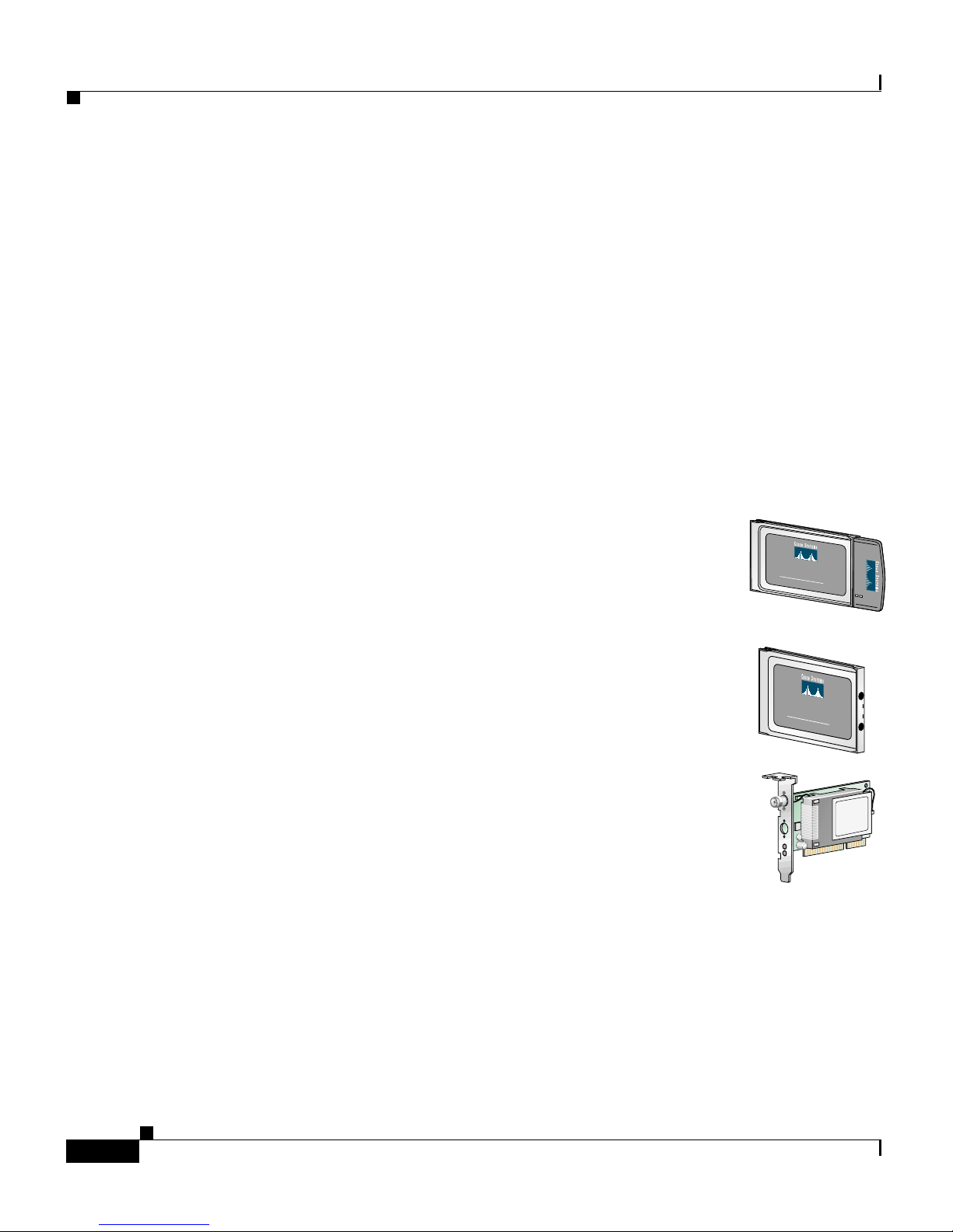
This do cu men t covers t h re e t yp es o f cl ient adapters:
• PC card client adapter (also referred to as a PC card) –
A PCM CI A ca r d rad io modu le th at can b e i nserted i nto
any dev ice equippe d with an external Type II or Type III
PC card slot . Host de vice s can in cl ude l ap tops , note bo ok
computers, personal digital assistants, and hand-held or
portable devices.
Chapter1 Product Overview
C
IS
C
O
A
I
R
O
N
E
T
3
11 Mbps WIRELESS LAN ADAPTER
4
0
S
E
R
I
E
S
• LM card client adapter (also re ferr ed to as an LM car d )
– A PCMCIA card radio module that can be inserted into
C
ISC
any device equipped with an inter na l Type II or Type III
PC card slot. Host devices usually include hand-held or
O
A
IR
O
N
E
T
340
1
1
M
b
SERIES
p
s W
IR
E
L
E
S
S
L
A
N
A
D
A
P
T
E
R
portable devices.
• PCI client adap ter – A clie nt ad ap te r ca rd rad io mod ul e
that can be inserted into any device equipped with
an empty PCI expansion slot, such as a desktop
compu ter.
Refer to the “Radio Antenna” section on page 1-4 for antenna differences between
these ad ap ter s .
Cisco Aironet Wireless LAN Adapters Hardware Installation Guide
1-2
OL-0795-01
Page 23

Chapter 1 Product Overview
Terminology
Throughout this document, the following terms are used:
• client a d apt er – Re fe rs to all thre e t yp es of ad ap t e rs
• PC card, LM card, or PCI client ada pter – Refers to only a specific adapter
• workstation (or station) – Refers to a computing device with an installed
client adap ter
Parts of the Client Adapter
The client adapter is composed of three major parts: a radio, a radio antenna, and
two L E Ds .
Parts of the Client Adapter
Radio
The client adapter contains a direct-sequence spread spectrum (DSSS) radio that
operates i n th e 2 .4 - G Hz li cen se -f r ee I n du st ri al S cientific M ed ica l ( I S M ) ba nd .
The radio transmits data over a half-duplex radio channel operating at up to 11
Mbps.
DSSS technology causes radio signals to be transmitted over a wide frequency
range, using multiple frequencies simul taneously. The benefi t of this technol ogy
is its a bi lit y to pro tec t the data transm iss i on f ro m interf er en ce. F or ex ample, if a
parti cular fre quency encounters noise or in terferenc e or both , enough redund anc y
is built into the signal on other frequencies that the client adapter usually will still
be successful in its transmission.
OL-0795-01
Cisco Aironet Wireless LAN Adapters Hardware Installation Guide
1-3
Page 24

Parts of the Client Adapte r
Radio Ant enna
Chapter1 Product Overview
The type of antenna used depends on your client adapter:
• PC cards have an integrated, permanently attached diversity antenna. The
benefit of the diversity antenna system is improved coverage. The system
works by allowing the card to switch and sample between its two antenna
ports i n orde r to s elect t he opt im u m port f or re ce i ving da t a p ackets . A s a
result, the card has a better chance of maintaining the radio frequency (RF)
connection in areas of interference. The antenna is housed within the section
of the card that hangs out of the PC card slot when the card is installed.
• LM cards are shipped without an antenna; however, an antenna can be
conne cted thr ough the card ’s external connector. If a snap-on antenna is used,
it should be operated in diversity mode. Otherwise, the antenna mode used
should correspond to the antenna port to which the antenna is connected.
• PCI client adap te rs ar e s h ip p ed w it h a 2 - dB i d i pole antenn a t ha t attaches t o
the adapter’s antenna connector. However, other types of antennas may be
used. PCI client adapters can be operated through the right antenna port on ly.
Note Refe r to the Ci sco Aironet Wireless LAN Ad apte rs So ftwa re
Configuration Guide for inf or mation o n settin g th e client ad ap ter’s
antenna mode.
Note External an ten n as u sed i n co m bin ati on w i th a p o w er set ti ng
resulting in a radiated power level above 100 mW equivalent
isotro pic r ad iated po wer ( EIR P ) are not all ow e d fo r us e w it hi n th e
Euro p ea n comm un it y and ot her co un tr ies tha t h a v e adop ted the
European R&TTE directive or the CEPT recommendation Rec 70.03
or both. For more details on legal com binatio ns of power levels and
antenna s i n th ose count ries , co nt act C is co C o rpo ra te Co m p li an ce.
See also the “Declaration of Con for mity wit h Rega rd to t he R& TTE
Directiv e 1 9 99/ 5/ EC” section on page C-4.
Cisco Aironet Wireless LAN Adapters Hardware Installation Guide
1-4
OL-0795-01
Page 25

Chapter 1 Product Overview
Security Features of the Client Adapter
LEDs
The client adap ter has tw o LEDs th at g lo w or b li n k to indi cate the s t atu s o f th e
adapter or to convey error messages. Refer to Chapter 4 for an interpretation of
the LED co d e s.
Securit y Features of the Clien t Adapter
The client adapter supports two principal security fe atures to protect y our data as
it is t ra nsmit t ed th rou gh y our wirel es s ne twor k: Wired Equivale nt Pri vacy (WEP )
keys and Extensible Authentication Protocol (EAP) or LEAP (also referred to as
EAP - Cisco Wireless).
WEP Keys
Note Refe r to the Ci sco Aironet Wireless LAN Ad apte rs So ftwa re
WEP is an optional IEEE 802.11 feature that provides your client adapter and
other devices on yo ur wirel ess ne twork wi th dat a confi dentia lity e quiv alent to that
of a wired LAN. It in vol ves packe t-by -pa c ket da ta en cr yptio n by th e t rans mit ting
devi ce and de c r yp tion by the rec e i ving de v ice.
Each device within your wireless network is assigned up t o four enc r yption ke ys,
called W EP keys, th at encrypt data befo re it is tr an s mi tt ed . I f a de vi ce r eceives a
packet th at is n o t e nc ry p ted with the ap pr o priate key (a s th e WEP k ey s o f all
devices m u st match), t h e d ev ice disca rds t he p ack et an d n eve r de livers it to th e
intend ed r ece iv er.
For the cl ient adap ter , W E P i s impleme nt ed through the client utilit ies . I n
Windows and Linux operating systems, the Client Encryption Manager (CEM)
utility allows you to set WEP keys, and the Aironet Client Utility (ACU) is used
to enab le W EP. In the Ma cO S 9 .x opera tin g sy s tem , W EP keys ar e set and
enabled in one ut ility.
Configuration Guide for instructions on setting WEP keys and
enabli ng W EP for y our sp ecific oper ati n g sy s t em.
OL-0795-01
Cisco Aironet Wireless LAN Adapters Hardware Installation Guide
1-5
Page 26

Security Features of the Client Adapter
EAP and LEAP
EAP is an optional IEEE 802.1x security feature that is ideal for organizations
with a large user base and access to an EAP-enabled Remote Authentication
Dial-In U ser S e rv ic e ( R A DIU S) ser v er, suc h a s C is co Se cu re A CS 2.6. Th e
RADIU S ser v er u ses E AP to prov id e s e rv er-b ased au thentica tio n f or clients.
Server-based authe nt ic ati on c a n be en ab led f o r yo ur cl ie nt ad ap ter i n on e o f tw o
ways:
• Through a host device and code built into its operating system (referred to as
• Through your client adapter’s firmware and Cisco software (referred to as
Chapter1 Product Overview
EAP)
LEAP)
This m ethod pr o vi de s au th en ti cat ion servi ce to client adap ters who s e h o s t
devices are not running an operating system with built-in EAP support. The
term LEAP is used to distinguish authentication provided by the client
firmwar e f r om authen ti cat io n pr o vi de d by a ho st an d its operat in g s ys tem.
For Wi ndows 95, 98, NT, 2000, or Me or future Windows operating systems, the
Aironet Client U tility set up pr og r am , wh ich in s tal ls the client ut ilities, is used to
enable LEA P o r EA P. After LEAP o r EA P is en ab led a nd t he co mp ut er is
rebooted , th e client ad ap ter auth en ti cat es to the R A D IUS server us in g th e
username and password entered by the user at the network logon. See the
“Installing the Client Utilities and Enabling LEAP or EAP” section on page 3-30
for ins truc t io ns on usi ng the Air one t Cl ie nt Ut il it y s etup pro gram to ena ble L EAP
or E A P.
For Windows CE, Linux, and MacOS 9.x, LEAP is enabled through a particular
scree n in the cli ent util ities. The userna me and pas sword ent ered in t his scre en are
used by the client adapter to authenticate to the RADIUS server. In Windows CE,
you do not need to re-enter your username and password after your device is
reboot ed or your cl ient ad apte r is e jec ted. In Linu x an d MacOS 9. x, the use rna me
and password need to be re-entered at the start of each new session. See the Cisco
Aironet Wirel ess LAN Adapters Softwa re Configuration Guide for instructions on
enabli ng LEAP th r ou g h t he client utilit ies .
Cisco Aironet Wireless LAN Adapters Hardware Installation Guide
1-6
OL-0795-01
Page 27

Chapter 1 Product Overview
When you enable EAP on your Access Points and LEAP or EAP on your client
adapter , au th en tication to the n et w or k o ccu r s in t he f ol lo w in g seque nc e:
1. The client adapter uses the username and password to start the authentication
2. The Access Point communicates with the EAP-compliant RADIUS server to
3. If the userna m e an d p ass w o rd ar e v al id , t he RA D I U S s er v er an d th e client
4. The client and A cce s s P o in t u s e th e WEP k ey f or a ll data transmissi on s
Network Configurations Using the Client Adapter
process .
authenticate the u ser na m e a nd p ass w o rd.
adapter negotiate a dynamic, session-based WEP key. The key, which is
unique for the authenticated client, provides the client with secure network
access.
during the session.
Note Refer to t he IEEE 802. 1 1 Standard f or more info rmation on EAP and
to the fo ll o wi n g U RL for ad ditional inform ation o n RA D I U S
servers: http://www.cisco.com/univercd/cc/td/doc/product/
software/ios120/12cgcr/secur_c/scprt2/scrad.htm.
Network Configurations U s ing the Client Adapter
The client adapter can be used in a variety of network configurations. In some
configurations, Access Points provide connections to your network or act as
repeater s to i nc re ase w i re less commu n ica tio n r an ge . Th e maxim um
communication range is based on how you configure your wireless network.
This section describes and illustrates the following common network
configu r ati ons :
• Ad ho c w i re less local area n et wo r k (LAN)
• Wireless inf ras truc ture with wor kstat ions access ing a wired LAN
Note For examples of more complex network configurations involving
client adapters and Access Points , refer to th e Cisco Aironet Access
Point Hardware Ins ta lla ti on Guid e .
OL-0795-01
Cisco Aironet Wireless LAN Adapters Hardware Installation Guide
1-7
Page 28
Network Configurati ons Using the Client Adapter
Note Refe r to the Ci sco Aironet Wireless LAN Ad apte rs So ftwa re
Configuration Guide for inf or mation o n settin g th e client ad ap ter’s
network mode.
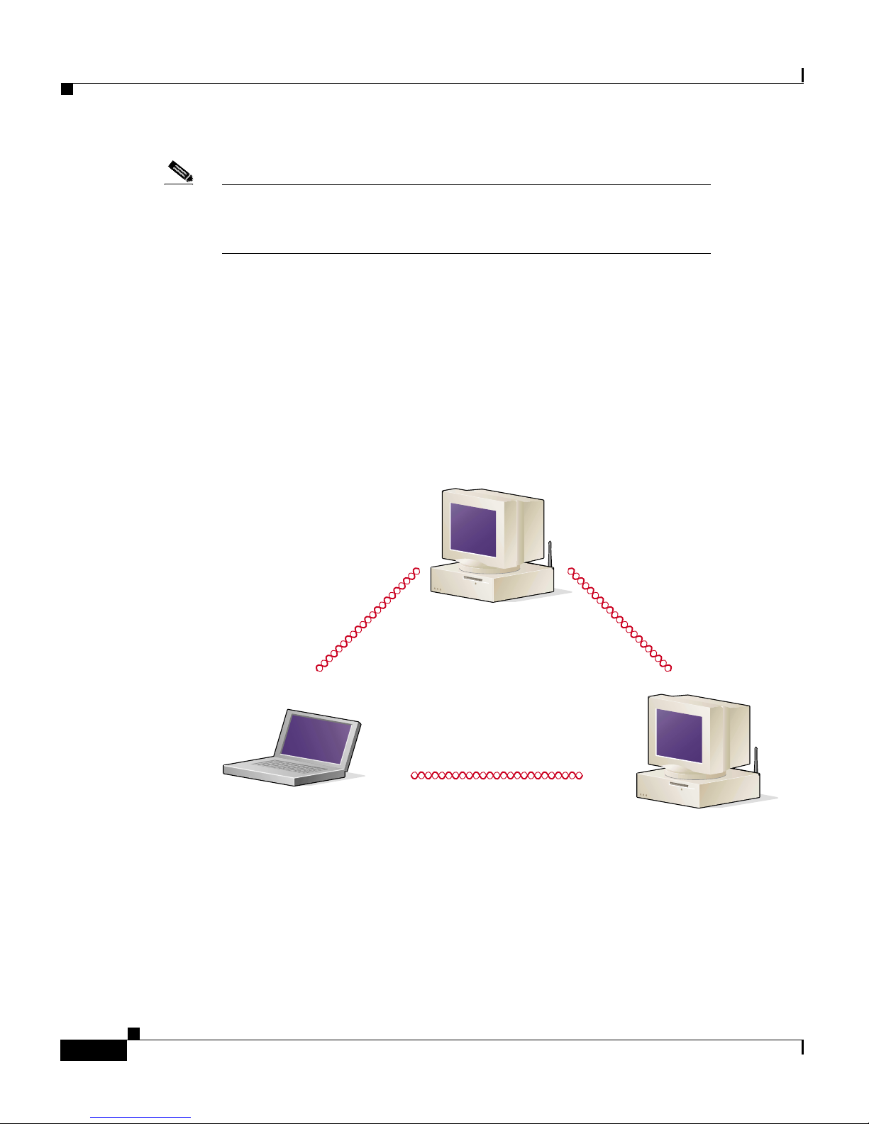
Ad Hoc Wirel ess LAN
An ad hoc (o r peer -to-pee r) wireless LAN (see Fig ure 1-1) is the simp lest wirel ess
LAN config ura t ion. In a wi re les s LAN us ing an ad hoc net work confi gu rati on , al l
devices eq ui pp ed w i th a cli en t a dapter ca n be linked to g et her and com m un ic at e
directly w it h each o th er.
Figure 1-1 Ad Hoc Wireless LAN
Chapter1 Product Overview
Cisco Aironet Wireless LAN Adapters Hardware Installation Guide
1-8
47520
OL-0795-01
Page 29
Chapter 1 Product Overview
Network Configurations Using the Client Adapter
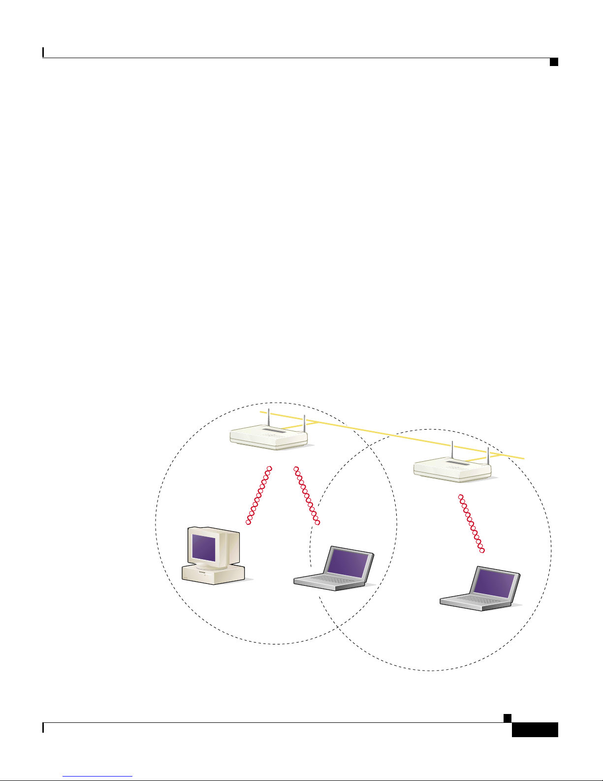
Wireless Infrastructure with Workstations Accessing
a Wired LAN
A microcellular network can be create d by placing two or more Access Points on
a LAN. Fig u re 1-2 sh ows a mi cr oc ell u lar ne tw o rk wit h w o rks ta ti ons acc es si ng a
wired LAN through several Access Points.
This configuration is useful with portable or mobile stations because it allows
them to be directly connected to the wired network even while moving from one
microcell domain to another. This process is transparent, and the connection to the
file server or host is maintained without disruption. The mobile station stays
connected to an Access Point as long as it can. However, once the transfer of data
packets needs to b e retried o r b eacons are m issed, the station au to matically
searches for and associates to another Access Point. This process is referred to as
seamless roaming.
Figur e 1-2 Wireless Infrastructur e w ith Workstations Acces sing a Wired LAN
Access Point
(Root Unit)
Wired LAN
Access Point
(Root Unit)
OL-0795-01
5835
Cisco Aironet Wireless LAN Adapters Hardware Installation Guide
1-9
Page 30

Positioning Your Wi reless Produ cts
Position ing Your Wir eless Produ cts
Deter mi ning the network location o f your wireless products can be infl uenced by
a number of factors. This section discusses those factor s and provides guideli nes
and tools for achieving optimum placement.
The site survey and link test tools provided with the client utilities can help you
to dete rmine the best pl ace m en t fo r A cce s s P o in ts a nd w o r kstations w ithin y ou r
wireless network. Refer to the Cisco A i rone t Wireless L AN Adap te rs Softwa re
Conf ig ur at ion Gu id e for informati on on using these to ols and to the Cisco Air one t
Acces s Poin t Hardwa re Instal latio n Gu ide f o r a dd itional infor mation on the
placemen t of A c ces s P o i nts .
Note The si te s urv ey and link t es t to ols are no t suppor te d in the L in u x
operatin g system.
Chapter1 Product Overview
Site Survey
Because of differen ce s in co mp o ne nt co n fi gur ati o n, pl ace m en t, an d ph y sica l
enviro nme nt, e very ne two rk appl i cat io n is a uniq ue inst all ati on. Befo re ins tall i ng
the sy ste m, you sh oul d pe rfo rm a si te s urve y to d et erm ine th e opt i mum util i zati on
of networking components and to maximize range, coverage, and network
performance.
Conside r t he fo ll owing ope rat ing and e nv ironm ent al c ond itio ns when perfo rm ing
a site survey:
• Data rates – Sensit ivity an d range ar e inverse ly prop ortiona l to data bit rate s.
The maximum radio range is achieved at the lowest workable data rate. A
decrease in r eceiver t hr esh o ld s en si tiv ity occu rs as t he r ad io d ata increa ses .
• Antenna type and placement – Prop er antenn a config ura tion is a critical
factor in maximizing radio range. As a general rule, range increases in
proportion to antenna height.
• Physical envir onment – Clear or open areas provide better radio range than
closed o r f il led areas. Al s o, th e l es s clu tt er ed th e work en vi r on men t, the
greate r th e r an ge.
Cisco Aironet Wireless LAN Adapters Hardware Installation Guide
1-10
OL-0795-01
Page 31

Chapter 1 Product Overview
Link Te st
Positioning Your Wir eless Products
• Obstruct io n s – A physical ob str uc tion s uch a s me tal she l ving or a st eel pill ar
can hinder performance of the client adapter. Avoid locating the works tation
in a location where there is a metal barrier between the sending and receiving
antennas.
• Building materi als – Radio penetra ti on is grea tly in fl ue nced by the bu il di ng
material used in construction. For example, drywall construction allows
great er range than co ncrete blocks. Metal or steel construction is a barrier to
radio signals.
The link test tool is used to determine RF coverage. The test results can help the
installer to el im i na te areas of low RF s i gn al leve ls t h at can result in a lo s s of
connec ti on b etw e en th e client a da pt er an d th e A ccess P oi nt.
OL-0795-01
Cisco Aironet Wireless LAN Adapters Hardware Installation Guide
1-11
Page 32

Positioning Your Wi reless Produ cts
Chapter1 Product Overview
Cisco Aironet Wireless LAN Adapters Hardware Installation Guide
1-12
OL-0795-01
Page 33

CHAPTER
2
Preparing for Installation
This c hapt er provi de s i nform ati on t hat yo u nee d to kno w befo re in stall i ng a c lie nt
adapter.
The following topics are covered in this section:
• Safety information, page 2-2
• Unpacking the Client Adapter, page 2-4
• System Re quir emen ts, page 2-5
• Site Requirements, page 2-6
OL-0795-01
Cisco Aironet Wireless LAN Adapters Hardware Installation Guide
2-1
Page 34

Safety inf orma ti on
Safety information
Follow th e guid eline s in this sectio n to ensur e prope r oper ation a nd safe use of the
client adap ter.
FCC Saf et y Complianc e St atement
The FC C, w ith its act io n in E T D ocket 96 -8 , h as adopted a sa fe ty s ta nd ar d f or
human ex po su re to RF elect rom a gn et ic energy em it te d b y F C C- ce rt if ie d
equipment. Cisco A i r o ne t products me et the uncon tr ol led env ir o nmental limits
found in OET-65 and ANSI C95.1, 1991. Proper operation of this radio device
accord ing to the instr ucti ons in th is publ icati on wil l resul t in user ex posu re
substantially below the FCC recommended limits.
Chapter2 Preparing for Installation
Safety Guidelines
• Do not touch or move the antenna while the unit is transmitting or receiving.
• Do not ho ld an y co m p o ne nt co nt ai ni ng a r ad io s u ch th at th e a nt en na is ve ry
close t o or to uching a ny expos ed part s of the body , especi ally th e face o r eyes ,
while tran smit ting .
• Do not operate the radi o or attemp t t o tr an sm it d at a u nl es s the ante nn a is
connected; otherwise, the radio may be damaged.
• Use in specific environments:
–
The use of wireless devices in hazardous locations is limited to the
constraints posed by the safety directors of such environments.
–
The use of wireless devices on airplanes is governed by the Federal
Aviation Administration (FAA).
–
The use of wireless devices in hospitals is restricted to the limits set forth
by ea ch hospi tal.
Cisco Aironet Wireless LAN Adapters Hardware Installation Guide
2-2
OL-0795-01
Page 35

Chapter 2 Preparing for Installation
• Antenna use:
Warnings
Observ e th e f o llo w in g w a r n in gs when o p er ati ng the cl ien t adapter :
Safety in fo rmation
–
In order to comply with FCC RF exposure limits, dipole antennas should
be located at a minimum distance of 7.9 inches (20 cm) or more from the
body of all persons.
–
High-gain, wall-mount, or mast-mount antennas are designed to be
profess ion ally instal led an d sh o ul d be located at a minimum di s tance of
12 inches (30 c m) or m or e from th e bo dy of all per sons. P lease contact
your professional installer, VAR, or antenna manufacturer for proper
insta lla ti on r e q ui r emen ts.
Warnin g
Warnin g
Do not operate your wireless network device near unshielded
blasting caps or in an explosive environment unless the device has
been modified to be especially qualified for such use.
In order to comply with RF exposure limits established in the ANSI
C95.1 standards, it is recommended w hen usi ng a laptop with a PC
card client adapter that the adapter’s integrated antenna is
positioned more than 2 inches (5 cm) from y our body or nearby
persons during extended p eriods of trans mitting or operating tim e.
If the antenna is positioned less than 2 inches (5 cm ) from the user,
it is recommended that the user limit exposure time.
Translated versions of these safety warnings are provided in Appendix B.
OL-0795-01
Cisco Aironet Wireless LAN Adapters Hardware Installation Guide
2-3
Page 36

Unpacking the Client Adapter
Unpacking the Client Adapter
Follow th es e s te ps to unp ac k the client adap ter:
Step 1 Open the shipp in g co nt ain er a nd ca re f ul ly r emo ve the co nt en ts.
Step 2 Return all packing materials to the shipping container and save it.
Step 3 Ensure that all items listed in the “Package Contents” section belo w are included
in the shi pment. Ch eck e ach item for d amage.
Note If any item is damaged or missing, notify your authorized Cisco
sales r ep res en ta tiv e. Any remote a nt en na an d it s asso ciated wi r in g
are shipped separately.
Chapter2 Preparing for Installation
Package Contents
Each client adapter is shipped with the following items:
• Cisco Aironet PC Card Client Adapter, Cisco Aironet LM Card Client
Adapt er , o r Cisco Air o net PCI C lient Ad apter
• Standard 2-dBi dipole antenna (for PCI client adapter)
• Quick Start Guide: Cisco Aironet Wireless LAN Adapters
• Cisco Aironet Series Wireless LAN Adapters CD
• Cisco Information Packet, which contains warranty, safety, and support
information
• Cisco product registration card
Cisco Aironet Wireless LAN Adapters Hardware Installation Guide
2-4
OL-0795-01
Page 37

Chapter 2 Preparing for Installation
System Requirements
In addition to the items shipped with the client adapter, you will also need the
following in order to install the adapter:
• A computing device (laptop, notebook, portable or hand-held device)
equipped with a Type II or Type III PC card slot or a desktop personal
computer equipped with an empty PCI expansion slot
Note All dri vers a nd su p po rti ng so ft w ar e ( C ard an d S o ck et
Services) for the PC card slot must be loaded and
configured. However, if you are using the Linux
operating system, a current version of Card and Socket
Services is provided on the Cisco Aironet Series
Wireless L A N A d ap ter s CD and ca n be ins ta lled and
configu r ed du rin g th e d r iv er in s t all ati o n p r oc ess . S ee
the “Inst all in g th e D river for Lin u x” section on
page 3-24.
System Requirements
• A Phillips screwdriver (for PCI client adapter)
• Windows NT Service Pack 3 or greater if your computer uses the Windows
NT operating system
• The following information from your system administrator:
–
Your wireless client name
–
The prot oc ol s n ecessary to b in d to th e cli en t a da pt er
–
The case-sensitive service set identifier (SSID) for your RF network
–
For Windows CE systems, the primary and secondary Domain Name
System (DNS) and Windows Internet Name Service (WINS) for your
computer
–
If you are not connected to a DHCP server, the IP address, broadcast
addre ss (if you are using th e L inux operating system), subnet mask, and
default gateway address of your computer
–
The username and password for your network account
OL-0795-01
Cisco Aironet Wireless LAN Adapters Hardware Installation Guide
2-5
Page 38

Site Re quirements
Site Re quirements
Becaus e th e client ad apter is a r ad io d evice, it i s susceptible to RF o b str u c ti on s
and com mon sourc es of int erfere nce th at can re duce t hroughput and ra nge. Fol low
these gu id el in es to en s u re th e b est possible perfo rmance:
• Install th e cli en t a dapter in an area wh er e large stee l structures such as
shelving units, bookcases, and filing cabinets will not obstruct radio signals
to and fro m the clie nt ad ap ter.
• Install the client adapter away from microwave ovens. Microwave ovens
operate o n th e s ame frequen cy as th e client ad ap te r an d can cause sign a l
interfer en ce.
Note Refe r to the “Positioning Your Wireless Products” section on
page 1-10 for additional guidelines on achieving optimum
placement of your workstation.
Chapter2 Preparing for Installation
Cisco Aironet Wireless LAN Adapters Hardware Installation Guide
2-6
OL-0795-01
Page 39

CHAPTER
3
Installing the Client Adapter
This chapter provides instructions for installing a client adapter and the client
utilities.
The following topics are covered in this section:
• Insert in g the Cli e n t A d ap te r i n to a Com p ut in g Device, page 3- 2
• Install in g th e C o rr ec t D r iv er, pa ge 3 -6
• Installing the Client Utilities and Enabling LEAP or EAP, page 3-30
• Verifying Installation, page 3-33
OL-0795-01
Cisco Aironet Wireless LAN Adapters Hardware Installation Guide
3-1
Page 40

Chapter 3 Installing the Client Adapter
Inser ting th e Client Adapte r i nto a Comp uting Dev ice
Inserting the Client Adapte r into a Computing Device
Note If you a re r unnin g Windows 95, 9 8, NT, or 20 00 and a C isco A iro ne t
client ad ap ter w as pr ev io u s ly in s t all ed on yo ur c omputer w ith the
6.10 driver, you must remove this driver before you can insert your
new cl ien t ad ap ter a nd i nstall its m o r e r ec e n t dr iv er. Ref er to t he
“Removing the 6.10 Driver” section on page 4-10 for instructions.
This section provides instructions for inserting a PC card or a PCI client adapter
into a co mput in g devi ce.
Caution The se p r ocedur es a nd the ph ys i c a l co nnecti on s they d es cr ibe ap ply
gener ally to conventional PC card sl ots and PCI expansion slots. In
cases of custom or nonconventional equipment, be alert to possible
differences in PC card slot and PCI expansion slot configurations.
Inserting a PC Card
Step 1 Before you begin, examine the PC card. One end has a dual-row, 68-pin PC card
connec to r. The card i s ke ye d s o i t c an b e in ser t ed on ly o n e w ay in t o t he P C car d
slot.
Note The PC card slot is on the left or right side of the computer,
depending on the model.
Cisco Aironet Wireless LAN Adapters Hardware Installation Guide
3-2
OL-0795-01
Page 41

Chapt er3 Installi ng the Client Adapter
Step 2 Follow the instructions below for your specific operating system:
• Windows 95 – The W indows 95 driver files are contained in a self-extracting
executa bl e f i le on th e Ci s co A ir o ne t Series Wirele ss LAN Adapters CD .
Before you in ser t the client adap ter, you m u st copy t hi s f ile to a flopp y di s k
or to a directory on your hard drive. Go to the “Install in g th e D r iv er for
Windows 95” section on page 3-7.
• Windows 98, Windows 2000, Windows Me, or Linux – Turn on your
comput er, let the operatin g system boot up co mplet ely, and follow the
remaining steps in this section to insert the PC card.
• Windows NT – Turn off your com p ut er, fo ll o w th e r emaining steps in th is
section to insert the PC card, and re boot your computer.
• Windows CE and MacOS 9.x – Th e d r iv er an d cli en t u t ili ti es mu s t be
insta lle d before y o u i n s er t t he P C car d . G o to t he “Installing the Correct
Driver” section on page 3-6.
Inserting the Client Adapter into a Computing Device
Caution Do not force the PC card into your computer’s PC card slot. Forcing
it will damage both the card and the slot. If the PC card does not
insert easily, remove the card and reinsert it.
Step 3 Hold the PC card with the Cisco logo facing up and insert it into the PC card slot,
applying just enough pressure to make sure it is fully seated (see Figure 3-1).
Figure 3-1 Inserting a PC Card into a Computing Device
OL-0795-01
Cisco Aironet Wireless LAN Adapters Hardware Installation Guide
3-3
Page 42

Inser ting th e Client Adapte r i nto a Comp uting Dev ice
Step 4 Go to the “Instal li ng th e Correct D r iv er ” section on page 3-6 to install the driver
for your computer’s operating system.
Note You can remove and rei nsert your PC card when necessary. Refer to
the “Remo ving a PC Ca rd” section on page 4-24 for instructions.
Inserting a PCI Client Adapter
Step 1 Turn off the PC and all its components.
Step 2 Remove the computer cover.
Chapter 3 Installing the Client Adapter
Note On most Pentium PCs, PCI expansion slots are white. Refer
to your PC documentation for slot identification.
Step 3 Remove the screw from the top of the CPU back panel above an empty PCI
expa nsion sl ot. Thi s s cr ew holds the m etal br acket o n th e back pa nel.
Caution Static el ectricity can d a m ag e y our cl ient adap te r. Before r emo v in g
the ada pt er f rom th e a nt i- static pack ag in g , d isc h arge s tat ic by
touching a metal part of a grounded PC.
Step 4 Examine the client adapter. The antenna connector and the LEDs face out of your
compute r and a re vi si ble whe n you put the cove r back on. The bot to m edge of the
adapter is the connector you will insert into an empty expansion slot in your
computer. See F ig ure 3-2 .
Cisco Aironet Wireless LAN Adapters Hardware Installation Guide
3-4
OL-0795-01
Page 43

Chapt er3 Installi ng the Client Adapter
Figure 3-2 Inserting a PCI Client Adapter into a PC
Antenna
connector
LEDs
Inserting the Client Adapter into a Computing Device
Card edge
connector
47521
Step 5
Standard 2 dBi
dipole antenna
Tilt the ad ap ter t o all ow th e a nt en na co nn ector and LED s t o sli p t h ro u gh th e
opening in the CPU back panel.
Step 6 Press t he cli en t adapter into th e em pt y s lo t u n ti l t he co nnector is f i rmly sea ted.
Caution Do not force the adap ter into the expa nsion s lot as thi s coul d damage
both the adapte r an d th e s l ot . If th e adapter d oe s n ot in s er t easily,
remove the ad ap ter and rein se rt it .
Step 7 Reinstall the s c re w on t he C P U ba ck p an e l and r ep la ce th e computer cover.
Step 8 Attach the 2-dBi antenna to the adapter’s antenna connector until it is finger-tight.
Do not over tigh te n.
Step 9 For op timal re cep ti o n, po s it io n th e antenna so it is s tr ai gh t up.
Step 10 Boot up your computer.
Note Because PCI client adapters are installed inside desktop computers,
you should have little reason to remove the adapter. However,
instructions are provided in the “Removing a PCI Client Adapter”
section on page 4-24 in case you ever need to remove your PCI
client adap ter.
OL-0795-01
Cisco Aironet Wireless LAN Adapters Hardware Installation Guide
3-5
Page 44

Installing the Correct Driver
Installing the Correct Driver
Note Before you be gin t he d riv er i nst all ati on pr ocess , m ake s ure y ou have
the installation disks for your computer ’s operating system nearby.
Some o p er ati ng sy s te m fil e s may be n eed ed t o complete the dr iv er
insta llation.
The driver you use for your client adapter depends on which operating system
your computer is running. This section provides instructions for installing the
correct driver for your operating system. Use Table 3-1 to quickly locate the
insta lla ti on instruct io ns fo r y ou r specific o p er ating sys t em .
Table 3-1 Locating Driver Installation Instructions
Chapter 3 Installing the Client Adapter
Operating System Page Number
Windows 95 3-7
Windows 98 3-11
Windows NT 3-13
Windows 2000 3-14
Windows Millennium Edition (Me) 3-16
Windows CE 3-18
Linux 3-24
MacOS 9.x 3-27
The proc ed ur es in this section as su m e yo u ar e i nst al lin g the driver f r om the CD
provi ded. If your compu ter does no t have a CD- RO M drive , do w nload th e dr iver
from Cisc o’s w eb s i te at http:/ /w w w.cisco.co m / pu b li c/s w - ce nt er /
sw-wireless.shtml. Under “Wireless S oftware Pr od ucts - Ci s co A ir o net Driv er s
and Util ities, ” select your computer ’s operating system and the appropriate
driver.
Cisco Aironet Wireless LAN Adapters Hardware Installation Guide
3-6
OL-0795-01
Page 45

Chapt er3 Installi ng the Client Adapter
Installing the Driver for Windows 95
Note Windows 95 limits your computer’s network connections to four. If
you try to install a client adapter when four network devices (such
as a PCMCIA Ethe r net card, dial- u p adapter, VPN adapter, dock ing
station Eth er ne t ca rd , et c.) are alr eady connec ted to yo u r co mp u ter,
the new adapter cannot establish a network connection.
The driver installation instructions vary for Windows 95 Version A and Version
B. You can determine which version your computer is running by selecting My
Computer, Control Panel, System, and General. The version of your
computer’s ope rating s y s tem is located under the System heading. If you ha ve
Windows 95 Version B, th e v e r si on n umber ends with the let ter B.
Installing the Correct Driver
• For Windows 95 Version A driver installation instructions, go to the
“Windows 95 Version A” section be l o w.
• For Wind ows 9 5 Version B d river installation instru ct io ns, go to th e
“Windows 95 Version B” section on page 3-9.
Wind ow s 95 Versi on A
If your computer’s operating system is Windows 95 Version A, follow these
steps.
Step 1 Insert t he Cisco Airon et Series Wireless LAN Adapters CD into your computer’s
CD-R OM driv e.
Step 2 Copy the Win95Driver. exe file from the Win95 directory on the CD to a floppy
disk or to a directory (other than the root directory) on your computer’s hard
drive.
Step 3 Remove the CD from your computer’s CD-ROM drive.
OL-0795-01
Cisco Aironet Wireless LAN Adapters Hardware Installation Guide
3-7
Page 46

Installing the Correct Driver
Step 4 Locate the W in95Dr iver . exe fil e on your flo ppy di sk or in a dire ctory on your ha rd
driv e and double-click it to extract the driver f iles. Unless you specify a different
locatio n , t he fi le s ar e p l aced o n th e floppy di sk.
Note Do not extract the files to the root directory of your hard
Step 5 Follow the instructions in the “Inserting the Client Adapter into a Computing
Device” section on page 3-2 to insert the client adapter.
Step 6 After you insert the client adapter into your computing device, Windows
automatically detects it and opens the New Hardware Found window.
Step 7 Select Driver from disk provided by hardware manufacturer and click OK.
Step 8 In the Install From Disk window, enter the path to the location where you
extrac ted t he Windows 95 d r iv er f il es . The def a ul t is A : \, so if you ex tr ac ted the
file s to the r oo t di rector y on a fl op py di sk, you d o not ha ve to en t e r a path. I f,
howeve r, you extracted the files to a directory on your h ard drive , you must enter
the entire path (for example, C:\Win95).
Chapter 3 Installing the Client Adapter
drive. Wi ndo ws 95 i s una bl e to read t he m fro m thi s lo cati on .
Step 9 Click OK.
Step 10 If you are prompted to insert the Windows 95 operating system disk, click OK
and do one of the following:
• If the W indo ws 95 opera ting syst em file s are ins talle d on your com puter , th ey
are usu all y located i n t he C:\Windows \ O pt io ns \ Ca bs fo ld er. Type
C:\Windows\Options\Cabs in the Copy files from dialog box. Click OK to
copy the required files.
• If Windows 95 prompts for the Windows 95 opera ting syst em CD, insert this
CD into your CD-ROM drive. If your CD-ROM drive is drive D, the path in
the dialog box should be D:\Win95. Click OK to copy the required files.
Step 11 After the files are copied, remove any disks from your computer.
Step 12 D oub le- cl ick My Computer, Control Panel, and Network.
Step 13 Select the C isco Systems w ireless LAN a dapter and click Propert ie s.
Step 14 In the client adapter Properties window, click the Advanced tab.
Step 15 Select Client Name. Type your computer’s unique client name in the Value
dial og b ox.
Cisco Aironet Wireless LAN Adapters Hardware Installation Guide
3-8
OL-0795-01
Page 47

Chapt er3 Installi ng the Client Adapter
Step 16 Select SSID. Type your RF network’s (case-sen s iti v e) S S ID in the Value dialog
box. Click OK.
Step 17 If you are prompted to restart your computer, click Yes.
Step 18 If you are not connected to a DHCP server, double-click My Computer,
Control Panel, and Network. Select TCP/IP -> Cisco Systems Wireless LAN
Adapter. Cl ic k the Propertie s button, select Specify an IP address, and enter
the IP address, subnet mask, and default gateway address of your computer
(which can be obtained from your system administrator). Click OK twice. When
prompted to restart your computer, click Yes .
The dr iv er in stallation is com p lete.
Wind ow s 95 Versi on B
Installing the Correct Driver
If your c ompu ter’s operating system is Windows 95 Version B, follow these steps.
Step 1 Insert t he Cisco Airon et Series Wireless LAN Adapters CD into your computer’s
CD-R OM driv e.
Step 2 Copy the Win95Driver. exe file from the Win95 directory on the CD to a floppy
disk or to a directory (other than the root directory) on your computer’s hard
drive.
Step 3 Remove the CD from your computer’s CD-ROM drive.
Step 4 Locate the W in95Dr iver . exe fil e on your flo ppy di sk or in a dire ctory on your ha rd
driv e and double-click it to extract the driver f iles. Unless you specify a different
locatio n , t he files are be placed on t he f lopp y di sk .
Note Do not extract the files to the root directory of your hard
drive. Wi ndo ws 95 i s una bl e to read t he m fro m thi s lo cati on .
Step 5 Follow the instructions in the “Inserting the Client Adapter into a Computing
Device” section on page 3-2 to insert the client adapter.
Step 6 After you insert the client adapter into your computing device, Windows
automatically detects it and briefly opens the New Hardware Found window.
OL-0795-01
Cisco Aironet Wireless LAN Adapters Hardware Installation Guide
3-9
Page 48

Installing the Correct Driver
Step 7 The Upda te D ev i ce D r iv er Wizard dial og b ox open s an d in dicates that Windo w s
will co mp lete the i ns t al lat io n of t he client ad ap ter . Click Next.
Step 8 If the Update Device Driver Wizard indicates that Windows was unable to locate
a driver f or the clien t ad ap ter , cli ck Other Locations.
Step 9 In the Select Other Location window, enter the path to the location where you
extrac ted t he Windows 95 d r iv er f il es . The def a ul t is A : \, so if you ex tr ac ted the
file s to the r oo t di rector y on a fl op py di sk, you d o not ha ve to en t e r a path. I f,
howeve r, you extracted the files to a directory on your h ard drive , you must enter
the entire path (for example, C:\Win95).
Step 10 Cl ick OK.
Step 11 W h en th e U p d ate Devic e D r iv er Wiza rd i nd ic ates that it has fo un d the driv er,
click Fin ish.
Step 12 When the Insert Disk window appears prompting you to insert the Aironet
Wireless LA N A d ap ter I n stal lation D isk , click OK.
Chapter 3 Installing the Client Adapter
Step 13 If a windows app ears in di cat in g that the pc x50 0.s ys fi le cou ld not be fo und , ent er
the sa me path that you en tered in S te p 9 and click OK.
Step 14 If you are prompted to insert the Windows 95 operating system disk, click OK
and do one of the following:
• If the W indo ws 95 opera ting syst em file s are ins talle d on your com puter , th ey
are usu all y located i n t he C:\Windows \ O pt io ns \ Ca bs fo ld er. Type
C:\Windows\Options\Cabs in the Copy files from dialog box. Click OK to
copy the required files.
• If Windows 95 prompts for the Windows 95 opera ting syst em CD, insert this
CD into your CD-ROM drive. If your CD-ROM drive is drive D, the path in
the dialog box should be D:\Win95. Click OK to copy the required files.
Step 15 Wh en pr o mp ted t o re start yo u r co mp ut er, remov e an y d i sks and click Yes.
Step 16 W h en th e c om pu te r re star t s , d oub le- cl ick My Computer, Control Panel, and
Network.
Step 17 Select the C isco Systems w ireless LAN a dapter and click Prop ert ie s.
Step 18 In the client adapter Properties window, click the Advanced tab.
Step 19 Select Client Name. Type your computer’s unique client name in the Value
dial og b ox.
Step 20 Select SSID. Type your RF network’s (case-sen s iti v e) S S ID in the Value dialog
box. Click OK.
Cisco Aironet Wireless LAN Adapters Hardware Installation Guide
3-10
OL-0795-01
Page 49

Chapt er3 Installi ng the Client Adapter
Step 21 If you are not conn ecte d to a DHCP ser ver, double-cli ck My Computer, Control
Panel, and Netwo r k. Select TCP/IP -> Cisco Systems Wireless LAN Adapter.
Click the Prop ert ie s button, select Specify an IP address, and enter th e I P
address, subnet mask, and default gateway address of your computer (which can
be obtained from your system administrator). Click OK.
Step 22 In the Network window, click OK.
Step 23 Wh en pr o mp ted t o re start your co mp ut er, click Yes.
The dr iv er in stallation is com p lete.
Installing the Driver for Windows 98
Installing the Correct Driver
Note Win dows 98 lim its your compute r’s networ k c o nnec tions to e ig ht. If
you try to install a client adapter when eight network devices (such
as a PCMCIA Ethe r net card, dial- u p adapter, VPN adapter, dock ing
station Eth er ne t ca rd , et c.) are alr eady connec ted to yo u r co mp u ter,
the new adapter cannot establish a network connection.
If your computer’s operating system is Windows 98, follow these steps.
Step 1 After you insert the client adapter into your computing device, Windows
autom a t ically detects i t, brie fl y opens the Ne w H a r d w are Found wi ndow, and
starts co llecting in f orm at io n f or a driver i nf o rm ation dat ab ase.
The Add New Hardware Wizard dialog box opens and indicates that Windows is
searchi ng f or n ew driv er s .
Step 2 Click Next. Another dialog box opens and asks what you want Windows to do.
Step 3 Select Search for the best driver for your device (Recommended) and click
Next.
Step 4 Select CD-ROM drive, desele ct a ll othe r op tions , i nse rt t he Ci sco Airone t Se ries
Wireless LA N A d ap ter s CD int o y o ur compute r’s CD-ROM dr ive, an d click
Next.
The hardware wizard finds the installation files on the CD and displays the search
results.
OL-0795-01
Cisco Aironet Wireless LAN Adapters Hardware Installation Guide
3-11
Page 50

Installing the Correct Driver
Step 5 When the client ad apt er dr iv er is d is p lay ed , click Next to copy th e re qu i re d f iles.
Step 6 During driver installation, you may be prompted to enter a path to the Windows
98 operating system files. If so, do one of the following:
• If the W indo ws 98 opera ting syst em file s are ins talle d on your com puter , th ey
• If Windows 98 prompts for the Windows 98 opera ting syst em CD, insert this
Step 7 The Add New Hardware Wizard window opens and indicates that the installation
is com pl ete. Clic k Fin ish.
Step 8 When pr o mp ted t o re star t you r co m p uter, re mov e th e C D an d cl ick Yes.
Chapter 3 Installing the Client Adapter
are usu all y located i n t he C:\Windows \ O pt io ns \ Ca bs fo ld er. Type
C:\Windows\Options\Cabs in the Copy files from dialog box. Click OK to
copy the required files.
CD into your CD-ROM drive. If your CD-ROM drive is drive D, the path in
the dialog box should be D:\WIN98. Click OK to copy the requir ed f il es.
Step 9 When th e compute r re star t s, d ou b le- cl ic k M y Computer, Control Panel, and
Network.
Step 10 Select the C isco Systems w ireless LAN a dapter and click Prop ert ie s.
Step 11 In the client adapter Properties window, click the Advanced tab.
Step 12 Select Client Name. Type your computer’s unique client name in the Value
dial og b ox.
Step 13 Select SSID. Type your RF network’s (case-sen s iti v e) S S ID in the Value dialog
box. Click OK.
Step 14 If you are not connected to a DHCP server, double-click My Computer,
Control Panel, and Network. Select TCP/IP -> Cisco Systems Wireless LAN
Adapter. Cl ic k the Propertie s button, select Specify an IP address, and enter
the IP address, subnet mask, and default gateway address of your computer
(which can be obtained from your system administrator). Click OK.
Step 15 In the Network window, click OK.
Step 16 Wh en pr o mp ted t o re start your co mp ut er, click Yes.
The dr iv er in stallation is com p lete.
Cisco Aironet Wireless LAN Adapters Hardware Installation Guide
3-12
OL-0795-01
Page 51

Chapt er3 Installi ng the Client Adapter
Installing the Driver for Windows NT
Note This proced ure requ ires th at your co mput er has Windows NT
Service P ack 3 o r gr ea ter.
If your computer’s operating system is Windows NT, follow these steps.
Step 1 If an er ro r message ap p ear s indicat in g th at at least o n e service o r dri ver faile d
during system setup, click OK.
Step 2 Follow th e s tep s b e l ow to obt ain an avail ab le interrup t re quest (IR Q ) :
a. Select Start > Programs > Administrative Tools > Windows NT
Diagnostics.
Installing the Correct Driver
b. Click the Reso u rces tab.
c. The used I R Qs ar e l ist ed in n umerical o r de r alo n g th e l ef t si de o f th e
Resources window. Write down th e number of an IRQ that is not bein g used.
You will need this IRQ for Step 12.
Step 3 On your computer desktop, double-click My Computer, Control Panel, and
Devices. Scroll down and select Pcmci a. Click Startup, select Automatic, and
click OK .
Note For PC car d s, also ensu re th at the Car d bus service is
deselected.
Step 4 Insert t he Cisco Airon et Series Wireless LAN Adapters CD into your computer’s
CD-R OM dr ive .
Step 5 Double- cl ic k My Computer, Control Panel, and Network.
Step 6 Click the Adapters tab an d select Add.
Step 7 In the Select Network Adapter window, click Have Disk.
Step 8 In the Insert Disk window, enter the letter of your CD-ROM drive (such as D:\)
and click OK.
Step 9 In the Select OEM Option bo x, select the C isco Systems wireless LA N a dapter
and click OK.
OL-0795-01
Cisco Aironet Wireless LAN Adapters Hardware Installation Guide
3-13
Page 52

Installing the Correct Driver
Step 10 In the Adapter Setup window, select Client Name. Type your computer’s unique
client name in the Value dialog box.
Step 11 Select SSID. Type your RF network’s (case-sen s iti v e) S S ID in the Value dialog
box.
Step 12 Enter an available IRQ number, which you obtained in Step 2.
Step 13 Cl ick OK and Close.
Step 14 The Microsoft TCP/IP Properties window should open. If it does not open,
double-click My Computer, Control Panel, and Network. Sel ect Protocols,
TCP/I P, and Propertie s .
Step 15 Perform one of the following:
• If you are connected to a DHCP server, select Obtain an IP address from a
• If you ar e no t co nne c te d to a DHCP serv er, sele ct Specify an IP address and
Chapter 3 Installing the Client Adapter
DHCP server. When asked if you want to enable DHCP, click Yes and OK.
enter the IP address, subnet mask, and default gateway address of your
comp uter (w hich can be ob tained f ro m yo ur system a dministr ator). C lick
OK.
Step 16 Wh en pr o mp ted t o re star t yo u r co m p ut er, remov e th e CD and click Yes.
The dr iv er in stallation is com p lete.
Installing the Driver for Windows 2000
If your computer’s operating system is Windows 2000, follow the se steps.
Step 1 After you insert the client adapter into your computing device, Windows 2000
automatically detects it and briefly opens the Found New Hardware window.
The Found New Hardware Wizard window opens and indicates that the wizard
will h el p y o u to install th e d r iv er.
Step 2 Click Next. Another window opens and asks what you want the wizard to do.
Step 3 Select Search for a s uit a ble d r iv er for my dev ic e ( reco mmended ) and cli ck
Next.
Cisco Aironet Wireless LAN Adapters Hardware Installation Guide
3-14
OL-0795-01
Page 53

Chapt er3 Installi ng the Client Adapter
Step 4 Select CD-ROM drives, d eselec t all other o ptio ns, in sert the Cisc o Air onet S eries
Wireless LA N A d ap ter s CD int o y o ur compute r’s CD-ROM dr ive, an d click
Next. The wi zard f in ds th e i ns t all at io n files on t he C D an d di spl ay s th e s ear ch
results.
Step 5 When the client ad apt er dr iv er is d is p lay ed , click Next to copy th e re qu i re d f iles.
Step 6 When you receive a message indicating that Windows has finished the
insta lla tion, c li ck Finish.
Step 7 Remove the CD from your computer’s CD-ROM drive.
Step 8 Double- cl ic k My Computer, Control Panel, and System.
Step 9 In the S y stem Proper ti es w i nd o w, click th e Hardware tab.
Step 10 Cl ick De vice M anager.
Step 11 In the Device Manager window, double-click Network Adapters.
Step 12 Ri gh t -click the Cisc o S y stems wi re less LAN ad ap ter.
Installing the Correct Driver
Step 13 Cl ick P roper ti es.
Step 14 In the client adapter Properties window, click the Advanced tab.
Step 15 In the A d vanced w i n do w, select C lient Name. Type your computer’s unique
client name in the Value dialog box.
Step 16 Select SSID. Type your RF network’s (case-sen s iti v e) S S ID in the Value dialog
box. Click OK.
Step 17 If you are not connected to a DHCP server, follow these steps:
a. Double- cl ic k My Computer, Control Panel, and Network and Dial-up
Connections.
b. Right-click Local A rea C o n nect io n .
c. Click Proper ties, Internet Protocol (TCP/IP), and Properties.
d. Click Use t he f o llo w ing I P address an d e nter t he IP ad dr ess , su bn et mas k ,
and default gateway address of your computer (which can be obtained from
your system administrator). Click OK.
e. In the Local Area Connection Properties window, click OK.
Step 18 If you are prompted to restart your computer, click Yes.
The dr iv er in stallation is com p lete.
OL-0795-01
Cisco Aironet Wireless LAN Adapters Hardware Installation Guide
3-15
Page 54

Chapter 3 Installing the Client Adapter
Installing the Correct Driver
Installing the Driver for Windows Millennium Edition (Me)
The first release of Windows Me comes with driver version 6.15, which is
installed automatically the first time you insert a client adapter. To upgrade to the
driver p r ovided with your new cl ient adap te r, fo l lo w these step s.
Step 1 Make sure the client adapter is in your computer and the computer is booted up.
Note If this is the first time you are inserting a client adapter into
your computing device, Windows Me autom atically d etects
it, updates the hardware information database, and installs
driv er versio n 6.15.
Step 2 Insert t he Cisco Airon et Series Wireless LAN Adapters CD into your computer’s
CD-R OM dr ive .
Step 3 Double- cl ic k My Co mputer, Control Panel, System, the Device Manage r tab,
and Network Adapters.
Step 4 Select th e C is c o A ir onet wireles s LAN ad ap ter. Click Properties.
Step 5 In the client adapter Properties window, click the Driver tab.
Step 6 Click the Update Driver button. The Update Device Driver Wizard window
appears.
Step 7 Select Specify the loca tion of the d river (Advan ced) and click Next .
Step 8 Select Search for a better driver than the one your device is using now
(Recommended).
Step 9 Make sure the Removable Media checkbox is deselected.
Step 10 Se le ct th e Specif y a lo cation checkbox and click the Browse button.
Step 11 Locate your computer’s CD-ROM drive and click Ne xt.
Step 12 When asked what you would like to install, select The updated driver
(recommended) and click Next.
Step 13 When a screen appears indicating the driver that will be installed and its location,
click Next.
Cisco Aironet Wireless LAN Adapters Hardware Installation Guide
3-16
OL-0795-01
Page 55

Chapt er3 Installi ng the Client Adapter
Step 14 If Windows cannot find the pcx500.sys file and requests that you insert the CD
(even though the CD is already in your computer’s CD-ROM drive), enter the
letter of your CD-ROM drive (such as D:) in the Copy files from dialog box and
click OK .
Step 15 W h en you are no ti fied that the in s ta lla tion is co m p let e, cli c k th e Finish button.
Step 16 Wh en yo u ar e pr o mp ted t o re s tar t yo u r com pu te r, rem ove t he CD and cli ck No.
Step 17 D oub le- cl ick My Computer, Control Panel, and Network.
Step 18 Select the Cisc o Systems wireless LAN a dapter. Click Properties.
Step 19 In the client adapter Properties window, click the Advanced tab.
Step 20 In the A d vanced w i n do w, select C lient Name. Type your computer’s unique
client name in the Value dialog box.
Step 21 Select SSID. Type your RF network’s (case-sen s iti v e) S S ID in the Value dialog
box. Click OK.
Installing the Correct Driver
Step 22 If you are not connected to a DHCP server, double-click My Computer,
Control Panel, and Network. Select TCP/IP -> Cisco Systems Wireless LAN
Adapter. Cl ic k the Propertie s button, select Specify an IP address, and enter
the IP address, subnet mask, and default gateway address of your computer
(which can be obtained from your system administrator). Click OK.
Step 23 In the Network window, click OK.
Step 24 Wh en pr o mp ted t o re start your co mp ut er, click Yes.
The dr iv er in stallation is com p lete.
OL-0795-01
Cisco Aironet Wireless LAN Adapters Hardware Installation Guide
3-17
Page 56

Installing the Correct Driver
Installing the Driver for Windows CE
Note Windows CE devices do not support PCI client adapters.
The drive r in sta lla ti on inst ruct io ns va ry depe ndin g on whi c h versi on of W in dow s
CE you are running, and the files you install vary depending on your device’s
processor. To determine the Windows CE version and the processor type, follow
the ins tr uc tions in the “Determining Windows CE Version and Processor Type”
section be lo w.
Determ i ning Wind ow s CE Versi on and Processor Type
Step 1 Perform one of the following:
Chapter 3 Installing the Client Adapter
• If your Windows CE device is a pocket PC (ppc) device, select Start >
Settings > the System tab > About. The Windows CE version and the
processor type are displayed. Go to Step 4.
• If your Windows CE device is a hand-held (hpc) device, select Start >
Settings > Control Panel > System. Go to S te p 2 .
Step 2 In the S y stem Proper ti es w i nd o w, select t he Device tab. The processor type is
displayed (such as MIPS 4000 Family).
Step 3 Select the System tab. The core system version indicates the version of Windows
CE th at the de vice is r unning (suc h as 2.11).
Step 4 For Win d ow s CE 2.11, go to th e “Windows CE 2.11” section on page 3-19.
For Windows CE 3.00, go to the “Windows CE 3.00” section o n page 3- 2 1.
Cisco Aironet Wireless LAN Adapters Hardware Installation Guide
3-18
OL-0795-01
Page 57

Chapt er3 Installi ng the Client Adapter
Wind ow s CE 2.11
If your computer is running Windows CE 2.11, follow these steps.
Step 1 Use a serial or USB cable to connect your Windows CE device to a laptop or PC
runnin g Active S ync. A mes sag e ap p ear s o n th e Window s CE device in di cat in g
that it is co nn ecting to t he host .
After t he W i ndo ws CE devi ce is con nect ed, the Ne w Par tn ers hip win dow a pp ears
on the laptop or PC. This window asks if you want to set up a partnership.
Step 2 Perform one of the following:
• If you want to establish a partnership that allows you to synchronize files
betwe en th e lapt op or PC and t he W i nd ows C E de vi ce, se lect Yes, click Next,
and fo ll ow th e i ns t ru ct io n s o n t he sc r ee n to s p eci fy t he f iles to b e
synch r onized a n d to finis h s ettin g up the pa rtners hip.
Installing the Correct Driver
• If you do not want to synchronize files and want to connect as a “gu e s t,”
select No an d click Next. The screen in d ic ates that y ou ar e co nn ec ted a s a
guest.
Step 3 Insert the Cisco Aironet Seri es Wirele ss LAN Adapters CD into the laptop or PC’s
CD-ROM drive.
Step 4 Use Windows Explorer to browse the CD and locate the aironet.dll file and the
*.htm ( h elp ) files in t he d irectory stru cture th at co rres p o nd s t o th e d ev ice and
processor type of your Windows CE device.
Example: If you are running Windows CE 2.11 on a MIPS processor, the
appropriate aironet.dll file and the help files would be located in the
following directory structure: WinCE\Ce2.11\Mips.
Step 5 Drag a nd drop t he appr opr ia te airo ne t.dl l fi le a nd the help fi le s f rom t he CD t o t he
\Windows directory on the Windows CE device.
Step 6 On the Windo w s C E d ev ic e, cr eat e a folder e nt it led Cisco in the
\Windows \Pr o gr ams directory. Creating this fold er w i ll enable yo u to access th e
client ut ili ties from Start > Pr o gr ams > Ci s co af te r th e u ti lities ar e i n stal led.
OL-0795-01
Cisco Aironet Wireless LAN Adapters Hardware Installation Guide
3-19
Page 58

Installing the Correct Driver
Step 7 Drag an d dr o p th e c lient utility files, which have an .exe ex tensio n, f r om the CD
to the \Windows\Progra ms\C isc o di rec to ry of th e W in dows C E dev ic e. The cli en t
utility f il es ar e l ocated i n a d ir ec to ry s p ec if ic to the Windows CE version and
processor type.
Example: The client utility files for Windows CE 2.11 on a MIPS processor
Step 8 After th e fi les are cop ie d, remove th e CD.
Step 9 Disconnect the Windows CE device and reboot it.
Step 10 Follow the instructions in the “Inserting the Client Adapter into a Computing
Device” section on page 3-2 to insert the client adapter into the PC card slot of
the Windows C E device.
The Unidentifi ed PCCard Adapter dialog box appears with the driver name se t to
Netwo r k car d in S o ck et X . I f th e d r iv er n am e is s et to an ything ot he r th an a
network card, remove the client adapter, reset the Windows CE device, and
reinser t the clie nt ad ap ter.
Chapter 3 Installing the Client Adapter
would be located in the following directory structure:
WinCE\ Ce2.11\Mi ps.
Step 11 Type aironet for the dr iv er n ame and cl ick OK.
The Windows CE de vi ce sh o ul d c on f ig ure t he cli en t ad ap ter, and the green LED
on the adapter should blink. If this does not happen, remove the client adapter,
reset th e Wind ows C E device, an d go b ack to Step 1 0 .
Step 12 The Air o net Wireless LAN A dapte r S etting s dialog b ox appe a r s . P er f orm one of
the fo ll ow i ng :
• If you are connected to a DHCP server, select Obta in an IP address via
DHCP or Use server-assi gned IP add ress and click OK.
• If you are n o t connected to a DHCP server, select Spec ify an IP address or
Use specific IP address and follow the steps below:
a. Enter the IP address, subnet mask, and default gateway address of your
comp uter (w hich can be ob tained f ro m yo ur system a dministr ator).
b. Select th e N a me S erv er s tab and ente r th e p ri mar y an d s eco ndar y D N S
and WI NS fo r y our co m p uter ( w hi ch ca n b e ob ta in ed f rom yo u r s yst em
administrator).
c. Click OK.
Cisco Aironet Wireless LAN Adapters Hardware Installation Guide
3-20
OL-0795-01
Page 59

Chapt er3 Installi ng the Client Adapter
Step 13 Select Start > Programs > Cisco > Aironet Client Utility to open th e A i ro n et
Client Utility (AC U ) .
Step 14 Select Client Name under Property. Type your Windows CE device’s unique
client name in the Value dialog box.
Step 15 Select SSID under Property. Type your RF network’s case-sensitive SSID in the
Value dialog box.
Step 16 Select Data Rates under Pr op er ty. Mak e su r e A u to is select ed in the lis t o f
options in the Value dialog box.
Step 17 Cl ick OK.
Step 18 If prompted , ej e ct t he c lien t a dap ter a nd rein s ert i t for the chan ge d se tti ngs to take
effect.
Step 19 Th e d r iv er an d client ut ility inst allation is c omplete. Refer to t he Cisco Aironet
Wireless LAN Adapters Software Configu ration Guide for instructions on how to
use ea ch u til ity.
Installing the Correct Driver
Wind ow s CE 3.00
Step 1 Use a serial or USB cable to connect your Windows CE device to a laptop or PC
Step 2 Choose one of the following options:
If your computer is running Windows CE 3.00, follow these steps.
runnin g Active S ync. A mes sag e ap p ear s o n th e Window s CE device in di cat in g
that it is co nn ecting to t he host .
After t he W i ndo ws CE devi ce is con nect ed, the Ne w Par tn ers hip win dow a pp ears
on the laptop or PC. This window asks if you want to set up a partnership.
• If you want to establish a partnership that allows you to synchronize files
betwe en th e lapt op or PC and t he W i nd ows C E de vi ce, se lect Yes, click Next,
and fo ll ow th e i ns t ru ct io n s o n t he sc r ee n to s p eci fy t he f iles to b e
synch r onized a n d to finis h s ettin g up the pa rtners hip.
• If you do not want to synchronize files and want to connect as a “gu e s t,”
select No an d click Next. The screen in d ic ates that y ou ar e co nn ec ted a s a
guest.
OL-0795-01
Cisco Aironet Wireless LAN Adapters Hardware Installation Guide
3-21
Page 60

Installing the Correct Driver
Step 3 Insert the Cisco Aironet Seri es Wirele ss LAN Adapters CD into the laptop or PC’s
CD-ROM drive.
Step 4 Use W ind ows E xpl orer to b rowse t he CD a nd loc ate the *.c ab fi le in th e di rec tor y
structure that corresponds to the device and processor type of your Windows CE
devi ce .
Example: If you are running Windows CE 3.00 on a pocket PC device with a
Step 5 Drag and drop the appropriate *.cab file from the CD to the root directory (called
My Pocket PC or My Handheld PC) on the Wi ndows CE device.
Step 6 The File Conversion window appears indicating that some files may need to be
conve r te d. Clic k OK.
Chapter 3 Installing the Client Adapter
StrongAR M proc esso r, the appropria te *.ca b file would be loca ted in
the following directory structure: WinCE\Ce3.00\SA11xx and would
look so m ething lik e SA11xxPPC30v131.cab, where SA11xx
indic ate s the proce ss or type, PPC30 represents Windows CE vers ion
3.00 on a pocket PC device, and v131 indicates the driver version.
Step 7 After the *.ca b file is copied to the Windows CE devi ce, remov e the CD f r om the
laptop or PC and disconnect the Windows CE device.
Step 8 On you r Window s CE de vi ce, open File Exp l orer or Windows Explorer and
locate t h e * .ca b fi le in th e root dir ec to ry.
Step 9 Click the *.cab file to execute it. The cisco.dll driver is installed in the \Windows
direct or y, the cl ien t ut ilities ar e ex t ra cted to th e Win d ows \ S tar t M en u\
Programs\Cisco directory, and the *.cab file is removed.
Step 10 Follow the instructions in the “Inserting the Client Adapter into a Computing
Device” section on page 3-2 to insert the client adapter into the PC card slot of
the Windows C E device.
The Windows CE de vi ce sh o ul d c on f ig ure t he cli en t ad ap ter, and the green LED
on the adapter should blink. If this does not happen, remove the client adapter,
reset th e Wind ow s CE devi ce, and re in ser t t h e cl ient adap te r.
Cisco Aironet Wireless LAN Adapters Hardware Installation Guide
3-22
OL-0795-01
Page 61

Chapt er3 Installi ng the Client Adapter
Step 11 The Cisco Wireless LAN Adapter Settings dialog box appears.
• If you are connected to a DHCP server, select Obta in an IP address via
DHCP or Use server-assi gned IP add ress and click OK.
• If you are n o t connected to a DHCP server, select Spec ify an IP address or
Use specific IP address and follow the steps below:
a. Enter the IP address, subnet mask, and default gateway address of your
comp uter (w hich can be ob tained f ro m yo ur system a dministr ator).
b. Select th e N a me S erv er s tab and ente r th e p ri mar y an d s eco ndar y D N S
and WI NS fo r y our co m p uter ( w hi ch ca n b e ob ta in ed f rom yo u r s yst em
administrator).
c. Click OK.
Step 12 Select Start > Programs > Cisco > Aironet Client Utility to open th e A i ro n et
Client Utility (AC U ) .
Installing the Correct Driver
Step 13 Select Client Name under Property. Type your Windows CE device’s unique
client name in the Value dialog box.
Step 14 Select SSID under Property. Type your RF network’s case-sensitive SSID in the
Value dialog box.
Step 15 Select Data Rates under Pr op er ty. Mak e su r e A u to is select ed in the lis t o f
options in the Value dialog box.
Step 16 Cl ick OK.
Step 17 Th e d r iv er an d client ut ility inst allation is c omplete. Refer to t he Cisco Aironet
Wireless LAN Adapters Software Configu ration Guide for instructions on how to
use ea ch u til ity.
OL-0795-01
Cisco Aironet Wireless LAN Adapters Hardware Installation Guide
3-23
Page 62

Installing the Correct Driver
Installing the Driver for Linux
Note This procedure can be performed only by root users (those with
administrative rights).
Note Cisco ’s Linux driver currently supports version 2.2.xx of the Linux
kernel. To determine your kernel version, type uname -a and pr ess
Enter. The nam e of your computer and the L inux kern el versio n are
display ed . Fo r ex ample, in drake.cisco.com 2.2.15-4mak,
drake.cisco.com represents your computer’s name, and 2.2.15 is the
kernel version.
Chapter 3 Installing the Client Adapter
If your computer’s operatin g s yst em is Linux , f o llo w these st ep s.
Step 1 After you insert the client adapter into your computing device, insert the Cisco
Aironet Serie s Wire less LAN Adapters C D into your computer’s CD-ROM drive.
Step 2 Go to the Linux directory on the CD.
Step 3 Type sh ./cwinstall and press Enter.
Step 4 When yo u ar e as k ed to select wh er e y o u wa nt t he cli ent utili ti es to be in stalled,
perform one of the following:
• If you w an t t he files to b e i n s tal led i n th e s p ec if ied d e fa u lt lo ca tion, pr ess
Enter.
• If you want to specify a different location, enter the desired path and press
Enter.
Step 5 When you ar e a sked if you already have the source for Card and Socket Services
unpa cked , per fo rm on e of t he fol low in g:
• If you do not already have Car d and Socket S ervices un packed, type n, press
Enter, and go to Step 6.
• If yo u already have Card an d Socket Services unpacked, type y, press Enter,
and go to Step 7.
Cisco Aironet Wireless LAN Adapters Hardware Installation Guide
3-24
OL-0795-01
Page 63

Chapt er3 Installi ng the Client Adapter
Step 6 Version 3.1.21 of Card and Socket Services is provided on the Cisco Aironet
Series Wireless LAN Adapters CD. If you want this version to be unpacked into
the cur re n t d irectory (or in to t he /tmp di r ect or y if t he cu r re nt d ir ect or y is read
only) , type y an d press Enter, and go to Step 8.
Note If you want to use a different version of Card and Socket
Services, you can break away from this installation to obtain
a differ en t v er sio n f ro m t h e I nt er n et ( a t t he address
specified) and then continue the installation.
Step 7 When you are asked if you have already installed Card and Socket Services,
perform one of the following:
• If you ha ve not i ns t all ed Ca rd an d So ck et S er vi ces, typ e n, press Enter, and
go to Step 8.
Installing the Correct Driver
• If you ha ve al re ad y i n stal led Card an d Socket Se rvic es , ty pe y, press Enter,
go to the directory where the file is installed, and type make -f airo_cs.mk
insta ll. Go to Step 12.
Step 8 Type make config an d pres s Enter.
Step 9 When you are prom pted to respond to a series of questions, pre s s Enter to accept
the default value for each question.
Note The defaul t respo nse s for eac h quest ion ar e corre ct fo r most
users. Consult the PCMCIA-HOWTO for additional
information about each option.
Step 10 After you have responded to each question, type make all an d p r ess Enter.
Step 11 A fter th e make a ll co mm a nd i s f in ish ed ex ecuting, ty p e make install and press
Enter.
Step 12 Perform one of the following:
• If you do not want to limit access to the client utilities to root users (those
with a dminist ra tiv e ri gh ts ) , no acti on i s re q ui re d. P r oceed to S t ep 13.
• If you want only root use r s to be able to run the client utilities and configure
the cl ie nt ad ap te r, ty pe chmod 500 /path/acu (where path is the exact path to
where th e utilities w e re insta lle d in Ste p 4) , p r es s Enter, typ e c hmod 500
/path/cem, and pr ess Ente r.
OL-0795-01
Cisco Aironet Wireless LAN Adapters Hardware Installation Guide
3-25
Page 64

Installing the Correct Driver
Step 13 Perform one of the following:
• If you want your computer’s IP address to be assigned by DHCP and your
• If your co m p u ter i s no t co nnected to a D H CP s e rv er, fol low th e s t ep s be lo w
Chapter 3 Installing the Client Adapter
network has a DHCP server, you must run a DHCP client utility. The two
most popular client utilities are DHCP CD and Pump. Most Linux
distri but io ns shou ld have on e of the m. If yo u have neith er, you must install it
from you r dis tribu ti on CD-ROM or dow nlo ad one from t he Intern et. Re fer to
your distribution's home page for more information.
to enter the IP address, subnet mask, and default gateway address of your
computer.
a. Perform one of the following:
• If you want to set the IP address and have the system determine the
broadcast address and subnet mask, type ifco nf ig et h x IP address
(where x is th e n u m be r of y o ur cl ient adap ter and IP address is your
computer’s IP address) and press Enter.
• If you want to set the IP address and manually set the broadcast
address and subnet m ask, type if con fig ethx IP ad dress broadcast
broadcast address netmask netmask (where x is the number of your
client adap ter, IP address is your computer’s IP address, broadc as t
addre ss is the corresponding broadcast address, and netmask is your
subnet mask) and press En t er.
Note Your client adapter’s number is zero (0) if it is th e only
Ethernet ad ap ter ca rd in sta ll ed . Th e D ev ic e f iel d of th e
Statu s s cr een in th e A i ro n et Client U tility (A C U )
indica tes th e n umber of t he ad ap ter be in g u sed.
b. To enter the default gateway address, type route add default gw IP
addre ss of gateway netmask 0 . 0. 0.0 metric 1 (where IP address of
gateway is your default gateway address) and press Enter.
Step 14 Remove the CD and reboot your computer.
Step 15 Th e d r iv er an d client ut ility inst allation is c omplete. Refer to t he Cisco Aironet
Wireless LAN Adapters Software Configu ration Guide for instructions on how to
use ea ch u til ity.
Cisco Aironet Wireless LAN Adapters Hardware Installation Guide
3-26
OL-0795-01
Page 65

Chapt er3 Installi ng the Client Adapter
Note Linux a llo w s y ou t o in s ta ll the dr iv er s f or m o r e t ha n one
client ad ap ter and to th en select bet w een th e adapter s. (U p
to two PC cards and up to five PCI client adapters can be
supported.) To install the driver for another client adapter,
you can follow the previous instructions; however, the
proces s w il l be abbr ev i ate d n ow t ha t so me f il es ar e al re ad y
instal led . A f ter the d riv er s an d th e cli e n t u ti li tie s are
instal led , y o u can sw i tch b ack and fort h be tw ee n t he cl ient
adapters using the Select Radio parameter in ACU. See the
Cisco Aironet Wireless LAN Adapters Softwa re
Config ur a tion Gui d e f or i nf o r m at io n o n using th is
parameter.
Installing the Correct Driver
Installing the Driver for MacOS 9.x
Note Cisco Aironet PCI client adapters are not supported for use with
Apple co mp ut er s.
If you are using a n Apple Powe rBook G3 running MacOS 9.x, follow these ste ps.
Step 1 Boot up your PowerBook.
Step 2 Insert t he Cisco Airon et Series Wireless LAN Adapters CD into your computer’s
CD-R OM driv e . T h e Cisco pc3x 0 icon ap p ea r s on the desktop .
Step 3 Double- cl ic k t h e Cisco pc3x0 icon. The Cisco pc3x0 window appears.
Step 4 Double- cl ic k t h e Installer icon. If a window appears indicating that the
insta lla ti on cannot occur w ith oth er ap p lications r u nn in g , c lick the Continue
button.
Step 5 When the Cisco Wireless LAN Adapter Software screen appears, click Continue.
The Instal l w i nd o w app ear s .
The appli cat ion an d dri ver for t he Power Ma cint osh is sho wn in the middl e of the
window, and the proposed destination of the files to be copied is shown in the
Destina t ion F olde r in th e bott om le ft corne r of th e windo w. If you want to speci fy
a different folder, click t he S el ect F ol der bu tton a nd c h o os e a di fferent lo c ation.
OL-0795-01
Cisco Aironet Wireless LAN Adapters Hardware Installation Guide
3-27
Page 66

Installing the Correct Driver
Step 6 Click the Install button in the bottom right corner of the window.
Step 7 When a w i nd o w ap pe ar s in f or mi ng y o u th at the inst al lation requ ir es a restar t o f
your co mp ut er, cli ck th e Continue butt on.
Step 8 After th e fi les are cop ie d to the des ignated fold er in M a c in to sh H D , a window
appears indicating that the insta llation was successful. Click the Restart button.
Step 9 After your computer reboots, follow the instructions in the “Inserting the Client
Adapte r int o a Comp utin g De vi ce” sect io n on pa ge 3-2 to inser t the cli e nt ad ap ter
into your PowerBook’s PC card slot. Th e Ci sco Wireless LAN A dapter i con
appears on the desktop.
Step 10 Cl ic k t he ap ple-shap ed ic on i n th e t op l e ft corner o f th e d es k to p .
Step 11 Select Control Panels > AppleTalk. The AppleTalk window appears.
Step 12 M ak e su re th e name of th e c or r ect w irel es s LAN ada pter ap p ear s in the C onn ect
via dialog box. If it does not, click the up or down arrow on the right side of the
Conne ct vi a d ia lo g bo x an d select the correct ad ap ter.
Chapter 3 Installing the Client Adapter
Step 13 Close the AppleTalk window.
Step 14 Cl ic k t he ap ple-shap ed ic on i n th e t op l e ft corner o f th e d es k to p .
Step 15 Select Control Panels > TCP/IP. The TCP/IP wind o w ap p ear s.
Step 16 Select Cisco Wireless LAN Adapter in the Connect via drop-down box.
Step 17 Perform one of the following:
• If you are connected to a DHCP server, select Using DHCP Server in the
Config ure dr op-down box and type your compu ter’s u nique c lient name i n the
DHCP Client ID field.
• If you are not connected to a DHCP server, select Manually in the Co nfi gure
drop-down box and enter the IP address, subnet mask, router address, name
server a ddr ess, and sea rch dom ain s of you r comp uter (wh ic h can be obta ined
from your system administrator). On ly t he IP address an d subn et mask are
requ ired.
Step 18 Close the TCP/IP window.
Step 19 When a window appears asking if you want to save changes to the current
configuration, click the Save button.
Cisco Aironet Wireless LAN Adapters Hardware Installation Guide
3-28
OL-0795-01
Page 67

Chapt er3 Installi ng the Client Adapter
Step 20 Double-click the Macintosh HD icon on th e deskt op. The Macint osh HD window
appears.
Step 21 D oub le- cl ick the Cisco pcm3x0 Folder icon. The Cisco pcm3x0 Folder window
appears.
Step 22 Double-click the pcm 3x0 PPC icon. The Cisco pcm3x0 window appears, and the
comput er searches f or t he client ad ap ter. Afte r th e ad ap t er is f o un d , t he Cisco
pcm3x0 - B as i c Pr op ert ies wind o w ap p ears .
Step 23 Under Radio, make sure that radio status is on. If it is off, click the Turn r adi o
on bu tton .
Step 24 Perform one of the following:
• If your c ompute r is i n an infra str ucture n etw o r k, select Computer to base
station in the Network subwindow.
• If your computer is in a peer-to-peer (ad hoc) network, select Computer to
computer in the Network subwindow.
Installing the Correct Driver
Step 25 Type your RF network’s (case-sensitive) SS ID i n t h e S SI D d ial og b o x.
Step 26 Cl ick OK.
Step 27 Eject the CD by cl icking th e CD icon o n the des k to p an d draggi ng it to the tr as h
can.
Step 28 Th e d r iv er an d client ut ility inst allation is c omplete. Refer to t he Cisco Aironet
Wireless LAN Adapters Software Configu ration Guide for instructions on how to
use th e cli e n t u t ili ty.
OL-0795-01
Cisco Aironet Wireless LAN Adapters Hardware Installation Guide
3-29
Page 68

Chapter 3 Installing the Client Adapter
Installing the Client Utilities and Enabling LEAP or EAP
Install ing the Client Utilities and Enabling
LEAP or EAP
Note This section p r ov ides in str u ctions fo r in s talling t he client utilities
and e nabling LEAP or EAP for Windows 95, 98, NT, 2000, and Me.
If your computer is using a Windows CE, Linux, or Macintosh
operating system, the client utilities are installed with the driver (see
the “Installing the Correct Driver” section on page 3-6), and LEAP
is ena bl ed th r ou gh the c lient utilitie s ( re fe r to the Cisco Aironet
Wireless LAN Adapters Software Configuration Guide for
instructions).
After you have installed the appropriate driver for your computer’s operating
system, you ca n insta ll th e A ironet Cl ien t Utilit y ( A CU), Lin k S tatus Me t er
(LSM ), an d Client E n cr yp ti on Mana ge r ( C E M ) u til ities. A CU a llows you to
configu re the clien t adapter, enable s erver-bas ed auth entic ation , and enabl e the
Wired Encryption Privacy (WEP) feature; LSM provides troubleshooting and
status information; and CEM enables you to set one or more WEP keys for your
client adap ter.
3-30
Note The following procedure assumes you are installing the client
utilities from the CD provided. If your computer does not have a
CD-R OM dr iv e, down lo ad the ut ilities f rom Cisco ’s web site at
http:/ /ww w.cisco.com /p ubli c/s w-ce nter /sw- wirel ess. shtm l. Un der
“Wireless Software Products - Cisco Aironet Drivers and Utilities,”
select yo ur co m p uter’s operating system and the appropriate utility.
Cisco Aironet Wireless LAN Adapters Hardware Installation Guide
OL-0795-01
Page 69

Chapt er3 Installi ng the Client Adapter
Follow t he step s be low to i nsta l l the clie nt util it ies for W indo ws 95, 98, NT, 2000
or Me.
Step 1 Close any Windows programs that are running.
Step 2 Insert t he Cisco Airon et Series Wireless LAN Adapters CD into your computer’s
CD-R OM driv e.
Step 3 Select Start > Run and enter the following path (where D is the letter of your
CD-R OM dr ive) : D:\Utilities\ACU\setup.exe.
Step 4 When th e Welcome s creen appears, cl ick Next.
Step 5 In the A u th enticatio n M ethod sc re en , s el ect the se rver-based au th en tic at ion
method preferred f o r wi r eless netw o r k access in y o ur l oc ati on and c lick Next:
• If you select None (the defau lt v a lu e), s e rv er-b ased authent ica ti on i s no t
enabled for your client adapter. After the client utilities are installed, you can
elect no t to implement an y s ec ur it y fe atu r es, or you c an activate s o me level
of security by using WEP keys. Refer to the Cisco Aironet Wireless LAN
Adapters Software Configuration Guide for instr ucti on s on set ting WEP keys
using CEM and enabling WEP through ACU.
Installing the Client Utili ti es and Enabling LEAP or EAP
• If you select LEAP, LEAP is enabled on your client adapter, provided an
EAP-enabled RADIUS server is running on your network. After LEAP is
enabled and your computer is rebooted, your client adapter authenticates to
the RADIUS server using your network logon and receives a session-based
WEP key.
• If you select EAP, EAP is enabled on your client adapter, provided an
EAP-enabled RADIUS server is running on your network. If your computer
is not using an operating system with built-in EAP support, this option is not
available. After EAP is enabled and your computer is rebooted, your client
adapter authenticates to the RADIUS server using your network logon and
receives a session-based WEP key.
Step 6 In the Select Components screen, make sure the client utilities that you want to
install are selected and any that you do not want to install are deselected. Click
Next.
Step 7 In the Select Program Folder screen, click Next to allo w icons for t he clie nt
utiliti es t o be placed in t he Cisco Sy stems, In c. fold er.
OL-0795-01
Cisco Aironet Wireless LAN Adapters Hardware Installation Guide
3-31
Page 70

Installing the Client Utilities and Enabling LEAP or EAP
Step 8 In the Setup Complete screen, perform one of the following:
• If you selected no server-based au th en tication in S t ep 5 , sel ect Launch the
Airone t Clie nt Ut ilit y and click Finish. ACU opens so you can configure
your client adapter.
• If you sele cted LEAP o r EA P s e rver- b ased a ut he nt ica ti on i n St ep 5 , select
Yes, I want to restart my computer now, re m ove th e CD fr om your
computer’s CD-ROM drive, and click Finish. When the compute r re bo o ts,
enter yo ur us ername a nd pass word a t the n etwork l ogon sc reen. Follo wing the
sequence of events described in the “EAP an d LEAP” section on page 1-6,
the cli en t a dap t er is aut h en tic ated and ass ig n ed a session-b ased WEP k ey,
provid ed you r cli en t a da pt er is configu r ed to ass o ci at e t o a n EA P- en abl ed
Access P o in t.
Step 9 Refer to the Cisco Aironet Wi reless LAN Adapters Software Conf iguration Guide
for ins t ru ct io ns on h o w to u s e e ach utilit y.
Chapter 3 Installing the Client Adapter
Note Icons a re au to m a tically ad de d to th e desktop w h en y ou i nst all the
client ut ili ti es. I f you wi sh t o r emov e the se icon s fr om your d esk top ,
right-click the icon, click Delete, and click Yes to confirm your
decision.
Note To install or use the client utilities on Windows NT or Windows
2000 systems, you must log onto t he sy stem as a user w ith
adminis t r ative pri vi leges. Th e utilities do no t in s ta ll or operate
corre c tly fo r users no t logg ed in with administr a t ive ri gh ts .
Note If you ever need to uninstall the client utilities and the Aironet Client
Utilit y s etu p prog ra m, f ollow t he instructions in th e “Uninstalling
the Cli ent Util iti es a nd the Air o net Clie n t U t ili ty S etup Pr o gra m ”
section on page 4-25.
Cisco Aironet Wireless LAN Adapters Hardware Installation Guide
3-32
OL-0795-01
Page 71

Chapt er3 Installi ng the Client Adapter
Note After LEAP or EAP is enabled on your client adapter, you can
enable or d is a bl e i t a t a ny t im e u s in g ACU . R e fer t o th e Cisco
Aironet Wireless LAN Adapters Software Configuration Guide for
more information.
Verify ing Inst al latio n
To verify that you have properly installed the appropriate driver and client
utilities, perform one of the following:
• If your computer’s operating system is Windows 95, 98, NT, 2000, or Me,
open A CU by double-cli ck ing the ACU icon on your desktop. If the
installation w as s uc cess f u l, th e b ottom left corner o f th e A ironet Cl ien t
Utilit y scr een i nd ic ates that y ou r cl ien t ad ap ter i s ass o ci at ed to i ts A cc es s
Point.
Veri fy ing Insta llatio n
• If your computer’s operating system is Windows CE 2.11 or 3.0, open ACU
by se lecting Start > Programs > Cisco > Aironet Client Utility. If the
installation was successful, the bottom of the ACU screen indicates that your
client ad ap ter i s associated to its Acc ess Po in t.
• If your computer’s operatin g s yst em is Linux , g o to t he di r ect ory w he re th e
utiliti es w ere installed an d ty pe acu to open AC U . I f th e i nst allation w as
success fu l, th e b o tt om lef t co rn er o f th e Aironet Client U ti lit y s cr ee n
indica tes th at your cli ent ada pter is associa ted to its Acce ss Poin t.
• If your computer’s oper ating s ys t e m is MacOS 9.x, d ou bl e - click t he
pcm3x0PPC icon in the Cisco pcm3x0 folder to open the pcm3x0PPC client
utility. If the inst all at io n was su ccessful , th e top of t he Basic P r op er ti es
screen i nd i cat es t hat your cl ie nt ad ap ter is as soc iat ed to i ts Access P oi nt.
To ver if y th at yo u r client ada pt er i s au th en ticated an d ha s r eceived a
sessio n-b ased WEP key ( if yo u are r unn ing Windows 95, 98 , NT, 2000, or Me a nd
you enabled L EAP or EAP on your client ada pter), check the system tr ay on your
desktop. The WepStat icon, which looks like two connected computers, should
appear in t he system tr ay and ind ic a te th at L EA P or EA P is a ut henticated and
WEP is en ab le d. In a dd itio n, LEA P o r EA P and Enable W EP should be sel ect ed
in the N etw o r k Se cu ri ty s c re en in ACU .
OL-0795-01
Cisco Aironet Wireless LAN Adapters Hardware Installation Guide
3-33
Page 72

Verifying Installation
Note If your computer’s operating system is Windows CE, Linux, or
Note If your installation was unsuccessful or you experienced problems
Chapter 3 Installing the Client Adapter
MacOS 9.x, LEAP is en abled through the client utilities, not during
the ins tallation of t he utilities . F o r in fo rm at io n on enab l in g LEAP
and ve rify i ng au th en ti cation f or client ad ap ters that ar e u s ed w i th
these op er at in g s ys tems, refer to t he C isco A ironet Wirele ss LAN
Adapters So ft wa re C onfigurat io n Guide .
during or after driver installation, refer to Chapter 4 for
troubleshooting tips.
Cisco Aironet Wireless LAN Adapters Hardware Installation Guide
3-34
OL-0795-01
Page 73

CHAPTER
4
Troubleshooting and Routine
Procedures
This c hapt er pr ovi des g ener al i nform ati on for di ag nosi ng a nd corre cti ng commo n
problems encountered when installing or operating a Cisco Aironet Wireless LAN
Adapter as well as procedures for performing routine operations.
The following topics are covered in this section:
• Accessing the Latest Troubleshooting Information, page 4-2
• Usin g th e I n di c at or LED s , p a g e 4-2
• Proble m s af te r In stalling th e D r iv er, page 4-3
OL-0795-01
• Problems Obtaining an IP Address in Windows CE, page 4-7
• Problems Associating to the Access Point, page 4-8
• Problems Authenticating to the Access Point, page 4-8
• Problems Connecting to the Network, page 4-8
• Remo ving the Driver, page 4- 9
• Updating the Driver, page 4-18
• Remo ving the Clie nt A dapter, pa ge 4-24
• Uninstalling the Client Utilities and the Aironet Client Utility Setup Program,
page 4 -25
Cisco Aironet Wireless LAN Adapters Hardware Installation Guide
4-1
Page 74

Chapter4 Troubleshooting and Routine Procedures
Accessing the Latest Troubleshooting Information
Accessing the Lates t Troubles hooting Inf ormati on
This ch apte r pr ovide s ba sic tr oubl esh oot ing ti ps f or yo ur c lie nt adap ter. For mor e
up-to-d ate and co mplex t ro ubl eshoot i ng i nform ati on, re fer t o th e TAC web site at
http://www.cisco.com/tac. Select Wireless LAN under “Top Issues.”
Using the Indicator LEDs
The c lie nt adapter s ho w s m e s s ag es a nd error co nd it io ns th ro u gh i ts t w o LEDs:
• Link Integrity/Power LED (green) – T h is LED li g ht s w he n th e client
adapter is receiving power and blinks slowly when the adapte r is linked with
the network.
• Link Activity LED (amber) – This LED blinks quickly when the client
adapter is receiving or transmitting data and blinks in a repeating pattern to
indica te an er ror co n di ti on .
Table 4-1 interprets the LED operating messages.
Table 4-1 LED Operating Messages
Green LED Amber LED Condition
Off Off Cli en t a dapter is no t recei ving
power or an error has occurred.
Blinking quickly Blinking quickly Power is on, self-test is OK, and
client ad ap te r is scanning f o r a
network.
Blinki ng slowly Blinki ng quickl y Client ada pt er i s a ss oci at ed t o an
Acce ss P o in t.
Continuously on o r
blinking slowly
Blink in g Clien t adapte r is tr ansmitti ng or
receiv in g da ta w hi le as so ci ated
to an Access Point.
Cisco Aironet Wireless LAN Adapters Hardware Installation Guide
4-2
OL-0795-01
Page 75

Chapter 4 Troubleshooting and Routine Procedures
Table 4-1 LED Operating Messages (c ontinued)
Green LED Amber LED Condition
Off Blink in g quickly Client adapt er is in po wer sa ve
On Blinking quickly Client adapter is in ad hoc mode.
Off On Driver installed incorrectly.
Off B linking in a pa tt er n Indicates a n error co nd it io n .
Problems after In stalli ng the Driver
Problems after Installing the Driver
mode.
Note If you e xp erie nce pro bl ems d uring dri ver in s tall ati on , you may want
to restart the in stallation proce s s. G o t o t he “Rem o ving the D r iv er ”
section on page 4- 9 to start w ith a clean ins ta ll.
Foll ow th e in str uc tio ns i n thi s s ect ion if you e xp er ienc e d if fi c ulty wi th y our cli e nt
adapter after installing the driver (for instance, your computer repeatedly freezes
at the network login screen, the green LED does not blink to indicate that the
adapter i s ac ti ve , etc.).
Client Adapter Recognition Problems
If your client adapter is not being recognized by your computer’s PCMCIA
adapter, chec k yo ur c omputer’s BIOS and make sure that the PC card controller
mode is s et to PCIC compatible.
Note A comp uter’s BIOS varies depending on the manufacturer. For
support on B I OS -rel ated issu es, co nsu lt y ou r co mp ut er’s
manufacturer.
OL-0795-01
Cisco Aironet Wireless LAN Adapters Hardware Installation Guide
4-3
Page 76

Problems after Installing the Driver
If your computer’s operat in g system is M ac O S 9. x, v er if y th at th e d r iv er
(pcm3x0) and enablers (pcm3x0Enabler) are installed. They should be in the
Extensions folder of the System folder.
• If you can n ot f ind th e d r iv er, reinstall it a nd r estart th e co mp u ter.
• If the d ri ver is pr op er l y i n s tal led , eject th e c lient adap ter and re in s er t i t.
Missing Fil es in Windows CE
If you experience a problem after attempting to install the driver for Windows CE,
some necessary files may be missing.
• If you ar e usi ng W ind ows CE 2.11, locate the m fcce 21 1 .d ll , arp. d ll, dh cp .dll ,
ndis.dll, and network.cpl files on the Windows CE Services CD that was
shipped with your Windows CE device or obtain them from the device
manufacturer. Then use Windows Explorer to copy these files into the
\Windows directory of the Windows CE device and reinstall the driver
follo w in g t h e i ns t ru ct io ns in th e “Installing the Driver for Windows CE”
section on page 3-18.
Chapter4 Troubleshooting and Routine Procedures
• If you are using Windows CE 3.00, obtain the mfcce300.dll file from the
devi ce manu factur er, us e Windows Explorer to c o py it int o th e \ Wind ows
directory of the Windows CE device, and reinstall the driver following the
instructions in the “Installing the Driver for Windows CE” section on
page 3-18.
Resolving Resource Conflicts
If you encounter problems while installing your client adapter on a computer
running a Windows operating system, you may need to specify a different
interrupt request (IRQ) or I/O range for the adapter.
The default IRQ for the client adapter is IRQ 10, which may not work for all
systems. Follow the steps for your specific operating system to obtain an available
IRQ .
Cisco Aironet Wireless LAN Adapters Hardware Installation Guide
4-4
OL-0795-01
Page 77

Chapter 4 Troubleshooting and Routine Procedures
During installation the adapter’s driver installation script scans for an unused I/O
range. Th e installat io n can f ai l i f th e I / O ra nge found b y th e d r iv er in st all ation
script is occupied by another device but not reported by Windows. An I/O range
might not be reported if a device is physically present in the system but not
enabled under Windows. Follow the steps for your specific operating system to
obtain an ava ila bl e I /O rang e.
Resolving Resource Conflicts in Windows 95, 98, and Me
Step 1 Double- cl ic k My Co mputer, Control Panel, System, the Device Manage r tab,
and Network Adapters.
Step 2 Select the Cisco Systems wireless LAN ada pter.
Step 3 Click the Prop ert ie s button.
Problems after Installing the Driver
Step 4 In the G en er al scr een, the Device S tat us field indicat es i f a r eso ur ce p rob lem
exists . If a p r ob le m i s in d ica ted , click the Re sources tab.
Step 5 Deselect th e Use automatic settings checkbox.
Step 6 Under Resource Settings or Resource Type, click Input/Output Range.
Step 7 Look in the Conflicting Device list at the bottom of the screen. If it indicates that
the range is being used by another device, click the Change Setting button.
Step 8 Scroll through the ranges in the Value dialog box and select one that does not
conflict with another device. The Conflict Information window at the bottom of
the screen indicates if the range is already being used.
Step 9 Click OK.
Step 10 Under Resource Settings or Resource Type, click Interrupt Request.
Step 11 Look in the Conflicting Device list at the bottom of the screen. If it indicates that
the IRQ is being used by another device, click the Change Setting button.
Step 12 Scroll through the IRQs in the Value dialog box and select one that does not
conflict with another device. The Conflict Information window at the bottom of
the scre en in dicates if t he IR Q i s already be in g used.
Step 13 Cl ick OK.
Step 14 Reboot your computer.
OL-0795-01
Cisco Aironet Wireless LAN Adapters Hardware Installation Guide
4-5
Page 78

Problems after Installing the Driver
Resolving Resource Conflicts in Windows 2000
Step 1 Double- cl ic k My Computer, Control Panel, System, the Hard ware tab, Device
Manager, and Network Adapters.
Step 2 Select the Cisco Systems wireless LAN ada pter.
Step 3 In the G en er al scr een, the Device S tat us field indicat es i f a r eso ur ce p rob lem
exists . If a p r ob le m i s in d ica ted , click the Re sources tab.
Step 4 Deselect th e Use automatic settings checkbox.
Step 5 Under Resource Settings or Resource Type, click Input/Output Range.
Step 6 Look in the Conflicting Device list at the bottom of the screen. If it indicates that
the range is being used by another device, click the Change Setting button.
Step 7 Scroll through the ranges in the Value dialog box and select one that does not
conflict with another device. The Conflict Information window at the bottom of
the screen indicates if the range is already being used.
Chapter4 Troubleshooting and Routine Procedures
Step 8 Click OK.
Step 9 Under Resource Settings or Resource Type, click Interrupt Request.
Step 10 Look in the Conflicting Device list at the bottom of the screen. If it indicates that
the IRQ is being used by another device, click the Change Setting button.
Step 11 Scroll through the IRQs in the Value dialog box and select one that does not
conflict with another device. The Conflict Information window at the bottom of
the scre en in dicates if t he IR Q i s already be in g used.
Step 12 Cl ick OK.
Step 13 Reboot your computer.
Cisco Aironet Wireless LAN Adapters Hardware Installation Guide
4-6
OL-0795-01
Page 79

Chapter 4 Troubleshooting and Routine Procedures
Resolving Resource Conflicts in Windows NT
Step 1 Select Start > Programs > Administrative Tools > Windows NT Diagnostics.
Step 2 Click the Reso u rces tab.
Step 3 Click the IRQ button.
Step 4 The used I RQs ar e l ist ed in n umerical o r de r alo n g th e l ef t si de o f th e R es o urces
window. Write down the number of an IRQ that is not being used; you will need
it for Step 11.
Step 5 Click the I/O Port button.
Step 6 The used I/O ranges are listed in numerical order along the left side of the
Resourc es window und er Addre ss . W ri t e down an I/ O ra nge th at i s not b eing use d
(for example, if range 0100-013F is followed by 0170-0177 in the list, then
0140-0169 is an available range); you will need it for Step 13.
Problems Obtaining an IP Address in Windows CE
Step 7 Double- cl ic k My Computer, Control Panel, and Network.
Step 8 Click the Adapters tab an d select the C isco Airon et w ir el es s LAN adap ter.
Step 9 Click Proper ties.
Step 10 Select Interru pt under Property.
Step 11 Select the number of the unused interrupt from Step 4 in the Value drop-down
box.
Step 12 Select IO Base Address under Property.
Step 13 Select a value that is within the unused range you determined in Step 6. For
example, if your unused range is 0140-0169, you could select 150.
Step 14 Cl ick OK.
Problems Obtaining an IP Address in Windows CE
If your computer’s operating system is Windows CE 2.11 or 3.00 and your
network is set up to use DHCP to acquire an IP address, the DHC P lease renewal
may fail, especially in suspend/resume situations. To obtain an IP address, soft
reset your Windows CE device.
OL-0795-01
Cisco Aironet Wireless LAN Adapters Hardware Installation Guide
4-7
Page 80

Chapter4 Troubleshooting and Routine Procedures
Problems Associating to the Access Point
Problems Associating to the Access Point
Follow the instructions below if your client adapter fails to associate to the Access
Point.
• If possible, move your workstation a few feet closer to the Access Point and
try again.
• Make sure the client adapter is securely inserted in your computer’s PC card
slot or PCI ex pa nsi on sl ot.
• If you ar e u sin g a P C I cl ien t ad ap ter , m ak e su r e t he an tenna is s e cu re ly
attached.
• Make sure the Access Point is turned on and operating.
• Check th at all par ameters are s e t pr o pe rl y for b ot h the client ada pt er and th e
Access P o in t. The se i nc lu d e t he S SID , LEA P o r EA P activati on, WEP
activat io n, ne tw o rk t yp e, an d ch an ne l.
• If the client ad ap te r still fai ls to es t ab lis h c on tact, ref e r to the “Obtaining
T echnical Assistance” section on page xvii for technical support info rmation.
Problems Authenticating to the Access Poi n t
If your c lient adap te r is a 4 0- b it car d an d L EA P is enabled , th e adapter c an
associ ate to b ut not au th en t icate to A ccess Points usi ng 1 28 - bi t e ncrypti on . To
authenticate to an Access Point using 128-bit encryption, you have two options:
• Purchase a 128-bit cl ien t ad ap ter . Th is i s th e most se cur e op ti o n.
• Disable WEP for the client adapter and configure the adapter and the Access
Point to associate to mixed cells. This option presents a security risk because
your data is not encrypted as it is sent over the RF network.
Problems Connecting to the N etwork
After y ou hav e i nst all ed the appr opr ia t e driv er and c lie nt util itie s, cont act you r IS
department if you have a problem connecting to the network. Proxy server,
network pr otocol s , and fu rther authen ticatio n i nform ation m ight b e n e e ded to
connec t t o th e n et w or k .
Cisco Aironet Wireless LAN Adapters Hardware Installation Guide
4-8
OL-0795-01
Page 81

Chapter 4 Troubleshooting and Routine Procedures
Removing the Driver
This section provides instructions for removing a client adapter driver from your
comput er. Two ex amples o f w he n yo u ma y n ee d to r emo ve a driver a re li s ted
below:
• If you are running Windows 95, 98, NT, or 2000 and a Cisco Aironet client
adapter was previously installed on your computer with the 6.10 driver, you
must remove th is d r iv er b ef ore you can install a m o re r ece nt d rive r, such as
the one provided on the Cisco Aironet Series Wireless LAN Adapters CD.
• If you ex pe ri en ce di fficu lt y w h il e i nst alling th e dr iv er f o r yo u r com pu te r’s
operating system, you may want to abort the installation procedure and start
over. Howev er, before you attem p t t o in s ta ll the dr iv er ag ai n, you m u st fi rst
remove any part of the driver that you may have already installed.
Table 4-2 enables you to quickly locate the instructions for removing a driver for
your specific operating system.
Removing the Driver
Table 4-2 Locating Driver Removal Instructions
Operating System 6.10 Driver Driver Other Than 6.10
Windows 95 page 4-10 page 4-13
Windows 98 page 4-10 page 4-13
Windows NT page 4-11 page 4-14
Windows 2000 page 4-12 page 4-15
Windows Millennium (Me) Not applicable page 4-13
Windows CE 2.11 Not applicable page 4-16
Windows CE 3.0 Not applicable page 4-16
Linux Not applicable page 4-17
MacOS 9.x Not applicable page 4-17
OL-0795-01
Cisco Aironet Wireless LAN Adapters Hardware Installation Guide
4-9
Page 82

Chapter4 Troubleshooting and Routine Procedures
Removin g th e Drive r
Removing t he 6. 10 Driver
To determine if the 6.10 driver is installed on your computer, open the Aironet
Clie nt U tility (ACU) by clic ki ng on th e ACU ic o n on the d es k to p and s elect
Status from the Commands pull-down menu. The driver version is indicated in
the NDIS Driver Version field.
To uninstall the 6.10 driver, follow the instructions tha t apply t o your computer’s
operatin g system.
Remov i ng the 6 . 10 Driver for Wind ow s 95 and 9 8
Step 1 Make su r e t he pr ev i ou s cl ient adap te r is i n yo ur c omputer an d the compu ter i s
booted up.
Step 2 Right-click the WepStat icon in the syst em tr ay on your de skt op. This icon look s
like two connected computers.
Step 3 Click Terminate.
Step 4 Insert t he Cisco Airon et Series Wireless LAN Adapters CD into your computer’s
CD-R OM driv e.
Step 5 Open Windows Explorer and find the \Utilities\RmWep directory on your
computer’s CD-ROM drive .
Step 6 Double- cl ic k t h e Rm Wep.exe fi le.
Step 7 Minimize Windows Explore r.
Step 8 Double- cl ic k My Computer, Control Panel, and Network.
Step 9 In the Network window, select the Cisco Systems wireless LAN a dapter.
Step 10 Cl ick Remove and OK.
Step 11 Wh en pr o mp ted t o re start your co mp ut er, click No.
Step 12 M ax imi ze Windows Explorer.
Step 13 Cl ick View, Options or Folder O p tions, and View. Under Hidden files, make
sure Show all files is select ed , make sure th e Hide file extensions for known
file type s ch eck b ox i s d eselected, a nd cl ic k OK.
Cisco Aironet Wireless LAN Adapters Hardware Installation Guide
4-10
OL-0795-01
Page 83

Chapter 4 Troubleshooting and Routine Procedures
Step 14 Find your computer’s operating s y stem in the fo l lo wi n g t ab le , g o to th e path
listed, and delete th e file in d ica ted .
Operating System Location of File File to be Deleted
Windows 95 C:\Windows\Inf pc4800.inf
Removing the Driver
Windows 98 C:\Windows\Inf or
C:\Windo w s \I n f\ Other
Step 15 Remo ve the CD f rom your comp uter ’s CD-RO M drive.
Step 16 Shut down your computer.
Step 17 Remove the client adapter.
Step 18 G o to the “I nserting th e Client A d ap ter into a Comp ut in g D evice” section on
page 3-2 for instructions on inserting your new client adapter and installing the
latest d ri ve r.
Remov i ng the 6. 10 Driver for Wind ow s NT
Step 1 Make su r e t he pr ev i ou s cl ient adap te r is i n yo ur c omputer an d the compu ter i s
booted up.
Step 2 Right-click the WepStat icon in the syst em tr ay on your de skt op. This icon look s
like two connected computers.
pc4800.inf or
aironetnet x500.i nf
Step 3 Click Terminate.
Step 4 Insert t he Cisco Airon et Series Wireless LAN Adapters CD into your computer’s
CD-R OM driv e.
Step 5 Open Windows Explorer and find the \Utilities\RmWep directory on your
computer’s CD-ROM drive .
Step 6 Double- cl ic k t h e Rm Wep.exe fi le.
Step 7 Close Windows Explorer.
Step 8 Double- cl ic k My Computer, Control Panel, and Network.
Step 9 In the Network window, click the Adapters tab.
OL-0795-01
Cisco Aironet Wireless LAN Adapters Hardware Installation Guide
4-11
Page 84

Removin g th e Drive r
Step 10 Select the Cisc o Systems wireless LAN a dapter.
Step 11 Cl ick Remove.
Step 12 When asked if you wish to continue, click Yes and Close.
Step 13 Wh en pr o mp ted t o re start your co mp ut er, click No.
Step 14 Remo ve the CD f rom your comp uter ’s CD-RO M drive.
Step 15 Shut down your computer.
Step 16 Remove the client adapter.
Step 17 G o to the “I nserting th e Client A d ap ter into a Comp ut in g D evice” section on
Chapter4 Troubleshooting and Routine Procedures
page 3-2 for instructions on inserting your new client adapter and installing the
latest d ri ve r.
Removing the 6.10 Driver for Windows 2000
Step 1 Make su r e t he pr ev i ou s cl ient adap te r is i n yo ur c omputer an d the compu ter i s
booted up.
Step 2 Right-click the WepStat icon in the syst em tr ay on your de skt op. This icon look s
like two connected computers.
Step 3 Click Terminate.
Step 4 Insert t he Cisco Airon et Series Wireless LAN Adapters CD into your computer’s
CD-R OM driv e.
Step 5 Open Windows Explorer.
Step 6 Click Tools, Fol der Opt ions, and View.
Step 7 Under Hidden files and folders, make sure Show hidden files and folders is
selected , m a ke su re th e Hide file extensions for known file types checkbox is
deselect ed , an d cl ick OK.
Step 8 Find the \Utilities\RmWep directory on your computer’s CD-ROM drive.
Step 9 Double- cl ic k t h e Rm Wep.exe fi le.
Step 10 Go to C:\Windows \Inf and double-click the oemx.inf and oemx.pnf files, where x
equals a n umeral, to o pe n th em .
Step 11 D elete th e oem x.inf and oemx.pnf files that are labeled Aironet.
Cisco Aironet Wireless LAN Adapters Hardware Installation Guide
4-12
OL-0795-01
Page 85

Chapter 4 Troubleshooting and Routine Procedures
Step 12 Remo ve the CD f rom your comp uter ’s CD-RO M drive.
Step 13 If you are prompted to restart your computer, click Yes.
Step 14 W h en th e c om pu te r re star t s , d oub le- cl ick My Computer, Control Panel, and
Add/Remove Hardware.
Step 15 In the Add/Remove Hardware Wizard window, click Next.
Step 16 Cl ick Uninstall/Unplug a device. Click Next.
Step 17 Cl ick Uninstall a device. Click Next.
Step 18 From the Devices list, se lect the C isco Systems w ireless LA N adap ter. Click
Next.
Step 19 Cl ick Yes, I want to uninstall this device. Click Next.
Step 20 Cl ick Finish.
Step 21 Shut down your computer.
Removing the Driver
Step 22 Remove the client adapter.
Step 23 G o to the “I nserting th e Client A d ap ter into a Comp ut in g D evice” section on
page 3-2 for instructions on inserting your new client adapter and installing the
latest d ri ve r.
Removing a Dri ver Other Than the 6.10 Driv er
To uninstall a driver other than the 6.10 driver, follow the instructions that apply
to your computer’s operating system.
Remov i ng the Dri ver for Wi ndows 95, 98, and M e
Step 1 Double- cl ic k My Computer, Control Panel, and Network.
Step 2 In the Network window, select the Cisco Systems wireless LA N a dapter.
Step 3 Click Remove and OK.
Step 4 When pro m p ted to restart yo u r co mp ut er, click No.
Step 5 Open Windows Explorer.
OL-0795-01
Cisco Aironet Wireless LAN Adapters Hardware Installation Guide
4-13
Page 86

Removin g th e Drive r
Step 6 If your computer’s operating system is Windows 95 or 98, click View, Options
Step 7 Find your computer’s operatin g system in t he fo l lo wi n g t ab le , g o to the pa th
Chapter4 Troubleshooting and Routine Procedures
or Fol der Option s, and View. Under Hidden files, make sure Show a ll files is
selected an d cli ck OK .
listed, and delete th e file in d ica ted .
Operating System Location of File File to be Deleted
Windows 98 C:\Windows\Inf or
Windows Me C:\Windows\Inf\Other aironetnetx500.inf
Step 8 Find your computer’s operating system in the following table and delete the
pcx5 0 0.sys file fr o m t he path indic ated.
Operating Syste m Location of pcx500.sys File
Windows 95 C:\Windows\System\pcx500.sys
Windows 98 C:\Windows\System\pcx500.sys
Windows Me C:\Windows\System32\Drivers\pcx500.sys
Step 9 Restart yo u r co m p ut er.
Removing the Dr i ver for Wi ndows NT
C:\Windows\Inf\Other
pc4800.inf or
aironetnetx500.inf
Step 1 Double- cl ic k My Computer, Control Panel, and Network.
Step 2 In the Network window, click the Adapters tab.
Step 3 Select the Cisco Systems wireless LAN ada pter.
Step 4 Click Remove.
Step 5 When asked if you wish to continue, click Yes and Close.
Step 6 When pro m p ted to restart yo u r co mp ut er, click Yes.
Cisco Aironet Wireless LAN Adapters Hardware Installation Guide
4-14
OL-0795-01
Page 87

Chapter 4 Troubleshooting and Routine Procedures
Removing the Dr i ver for Windows 20 00
Step 1 Make sure the client adapter is installed in your computer. Otherwise, Windows
cannot find the adapter to remove it.
Step 2 Double- cl ic k My Computer, Control Panel, and Add/Remove Hardware.
Step 3 In the Add/Remove Hardware Wizard window, click Next.
Step 4 Click Uninstall/Unplug a device. C lick Next.
Step 5 Click Uninstall a device. Click Next.
Step 6 From the Devices list, select the Cisco Sy stems wireless L AN adapter. Click
Next.
Step 7 Click Yes, I want to uninstall this device. Click Next.
Step 8 Click Finish.
Removing the Driver
Step 9 Open Windows Explorer.
Step 10 Cl ick Tools, Folder Op tions, and View.
Step 11 Under Hidden files and folders, make sure Show hidden files and folders is
selected . Click OK.
Step 12 Go to C:\Windows \Inf and double-click the oemx.inf and oemx.pnf files, where x
equals a n umeral, to o pe n th em .
Step 13 D elete th e oem x.inf and oemx.pnf files that are labeled Cisco.
Step 14 Go to C:\Windows\System32\Drivers and delete the pcx500.sys file.
Step 15 Shut down your computer.
Step 16 Remove the client adapter.
Step 17 Turn y ou r co m p uter b ack o n.
OL-0795-01
Cisco Aironet Wireless LAN Adapters Hardware Installation Guide
4-15
Page 88

Removin g th e Drive r
Remov i ng the Dri ver for Wi ndows CE 2. 11
Step 1 Eject the client adapter and remove it from the Windows CE device.
Step 2 Select Start > Programs > Cisco > Cisco Aironet Uninsta ll . The Cisco Ai ronet
Uninstal l s c re en ap pe ar s.
Step 3 Select th e Uninstall Cisco Aironet Wi reless LAN Adapter checkbox.
Step 4 Click OK. The utility informs you that the adapter has been uninstalled.
The registry entries (but no files) are removed, and the system returns to the point
at which th e files ha ve ju s t be en co pi ed t o t h e Windo w s C E d e v ic e.
Remov i ng the Dri ver for Wi ndows CE 3. 00
Chapter4 Troubleshooting and Routine Procedures
Step 1 Eject the client adapter and remove it from the Windows CE device.
Step 2 Select Start > Settings > Control Panel > Rem ove Programs (on a hand-held
devi ce) or Start > Settings > System tab > Remove Programs (on a po ck et PC
devi ce ).
Step 3 Select the Cisco Systems wireless LAN ada pter.
Step 4 Click the Remove butt on.
Step 5 When asked to verify your decision to remove the adapter, click Yes.
Step 6 Click OK. The driver, client u til it ies , r e g istr y en tr i es , and Cisco directory ar e
removed.
Cisco Aironet Wireless LAN Adapters Hardware Installation Guide
4-16
OL-0795-01
Page 89

Chapter 4 Troubleshooting and Routine Procedures
Removi ng the Dri v er for Linux
Step 1 Insert t he Cisco Airon et Series Wireless LAN Adapters CD into your computer’s
CD-R OM driv e.
Step 2 Go to the Linux directory on the CD.
Step 3 Type sh ./cwuninstall and press Enter. If the uninstall is successful, the driver
and th e cl ient u ti lit ies are re moved. I f t he uni nst a ll pr oc ess fai ls , an er ror m essa ge
appears.
Removing the Driver for MacOS 9.x
Removing the Driver
Step 1 Double- cl ic k t h e Cisco pc3x0 icon on the desktop. The Cisco pc3x0 window
appears.
Step 2 Double- cl ic k t h e Installer i co n.
Step 3 When the Cisco Wireless LAN Adapter Software screen appears, click Continue.
The Instal l w i nd o w app ear s .
Step 4 In the top left corner of the Install window, click on the Easy Install pull-down
menu and select Custom Remove.
Step 5 Select th e Appl ication, driver and help files for Power Macintosh checkbox.
Step 6 Click the Remove butt on.
Step 7 When a window appears indicating that the removal cannot occur with other
applic ati on s r u nn in g , cl ick the Continue button.
Step 8 After you receiv e a message indicat ing that the removal was successful, click the
Restart button.
Step 9 Remo ve the c li e n t adapt er f ro m t he desk top by clicki ng o n the Cisco Wireless
LAN Adapter icon and dragging it to the trash can or by clicking on the Cisco
Wireless LAN Adapter icon and selecting the Eject co m mand in th e Sp ecial
menu.
Step 10 Remove the client adapter from your PowerBook’s PC card slot.
OL-0795-01
Cisco Aironet Wireless LAN Adapters Hardware Installation Guide
4-17
Page 90

Updating the Driver
Note If the uninstall process is not successful, refer to the Read Me file on
the Cisco Aironet Series Wireless LAN Adapters CD for information
on manually removing the necessary files.
Updating th e Driver
You can ob tain the latest dr i ve rs at http :// w w w.cisco.co m / pu b lic/sw-cen ter/
sw-wireless.shtml. Under “Wireless S oftware Pr od ucts - Ci s co A ir o net Driv er s
and Utilities,” select your comp uter’s operating system and copy the appropriate
driver to your hard drive or to a floppy disk.
Chapter4 Troubleshooting and Routine Procedures
Use Table 4-3 to quickly locate the instructions to upgrade the driver for your
specific operating system.
Table 4-3 Updating the Dri ver Instructions
Operating System Page Number
Windows 95 4-19
Windows 98 4-19
Windows NT 4-19
Windows 2000 4-20
Windows Millennium Edition (Me) 4-21
Windows CE 4-22
Linux 4-23
MacOS 9.x 4-23
Cisco Aironet Wireless LAN Adapters Hardware Installation Guide
4-18
OL-0795-01
Page 91

Chapter 4 Troubleshooting and Routine Procedures
Upgrading t he D r iver f or Windows 95 and 98
Step 1 Make sure your client adapter is installed in your computer.
Step 2 Double- cl ic k My Co mputer, Control Panel, System, the Device Manage r tab,
and Network Adapters.
Step 3 Select the Cisco Systems wireless LAN ada pter.
Step 4 Click Proper ties.
Step 5 Select th e Dr iver tab.
Step 6 Click the Change Driver or Update Driver button.
Step 7 The Update Device Driver Wizard window appears. Click Next.
Step 8 Select Search for a better driver than the one your device is using now
(Recommended) and click Next.
Updating the Driver
Step 9 Select the location of the new driver (floppy disk drive or specify a location),
deselect the oth er options, enter the f ull path to the new driver (if you selected to
specify a location ), and click Next.
Step 10 A message ap p ear s i nd ic at in g th at the sys te m i s r ead y to in s t all th e new driver.
Click Next and Finish.
The driv er up g rade is comp lete, and th e ol d d ri ver is overw r it ten by the new one.
Upgrading t he D ri ver f o r Wi ndow s N T
Step 1 Make sure your client adapter is installed in your computer.
Step 2 Double- cl ic k My Computer, Control Panel, Network, and Adapters.
Step 3 Select the Cisco Systems wireless LAN ada pter.
Step 4 Click the Update button.
OL-0795-01
Cisco Aironet Wireless LAN Adapters Hardware Installation Guide
4-19
Page 92

Chapter4 Troubleshooting and Routine Procedures
Updating the Driver
Step 5 In the Windows NT Setup window, enter the full path to the new driver (for
example, you would enter A:\ if you copied the file to the root of a floppy disk)
and click Continue.
Step 6 Follow th e in s tructions o n th e s c r een to c omplete th e up g ra de process.
Upgrading t he D ri ver f o r Wi ndow s 2000
Step 1 Make sure your client adapter is installed in your computer.
Step 2 Double- cl ic k My Computer, Control Panel, System, the Hard ware tab, Device
Manager, and Network Adapters.
Step 3 Select the Cisco Systems wireless LAN ada pter.
Step 4 Select th e Dr iver tab.
Step 5 Click the Update Driver button.
Step 6 The Update Device Driver Wizard window appears. Click Next.
Step 7 Select Search for a suitable driver for my device (Recommended) and click
Next.
Step 8 Select the location of the new driver (floppy disk drive or specify a location),
deselect the other options, and click Next.
Step 9 Enter the full pat h to th e new dri ver (if yo u sel ect ed to s p eci f y a lo ca tion) and
click OK .
Step 10 A message ap p ear s i nd ic at in g th at the sys te m i s r ead y to in s t all th e new driver.
Click Next and Finish.
The driv er up g rade is comp lete, and th e ol d d ri ver is overw r it ten by the new one.
Cisco Aironet Wireless LAN Adapters Hardware Installation Guide
4-20
OL-0795-01
Page 93

Chapter 4 Troubleshooting and Routine Procedures
Upgrading the Driver for Windows Me
Step 1 Make sure your client adapter is installed in your computer.
Step 2 Double- cl ic k My Co mputer, Control Panel, System, the Device Manage r tab,
and Network Adapters.
Step 3 Select the Cisco Systems wireless LAN ada pter.
Step 4 Click Proper ties.
Step 5 Select th e Dr iver tab.
Step 6 Click the Update Driver button. The Update Device Driver Wizard window
appears.
Step 7 Select Specify the loca tion of the d river (Advan ced) and click Next .
Step 8 Select Search for a better driver than the one your device is using now
(Recommended) and click Next.
Updating the Driver
Step 9 Select the S p eci f y a lo ca ti on c heckbox, deselect the other options, enter the full
path to the new driver, and click Next.
Step 10 A message ap p ear s i nd ic at in g th at the sys te m i s r ead y to in s t all th e new driver.
Click Next and Finish.
The driv er up g rade is comp lete, and th e ol d d ri ver is overw r it ten by the new one.
OL-0795-01
Cisco Aironet Wireless LAN Adapters Hardware Installation Guide
4-21
Page 94

Updating the Driver
Upgrading t he D ri ver f o r Wi ndow s C E
The inst ructio ns for upgra ding the dri ver vary de pending on the format of th e new
driver (*.dll versus *.cab files). Follow the instructions for the format of your new
driver.
*.dll Files
If your new driver has a .dll extension, follow these steps.
Step 1 Eject the client adapter and remove it from the Windows CE device. This causes
the existing driver to unload from memory.
Step 2 Copy the new *.dll file to the \Windows dire ctory.
Step 3 Insert the client adapter. The new *.dll file is used.
Chapter4 Troubleshooting and Routine Procedures
*.ca b Files
If your new driver has a .cab extension, follow these steps.
Step 1 Copy the new *.cab file to your Windows CE device.
Step 2 Eject the client adapter and remove it from the Windows CE device. This causes
the existing driver to unload from memory.
Step 3 Execute the new *.cab file. A message appears indicating that the Cisco Systems
wireless LAN adapter is alre ady installed.
Step 4 Click the OK button to re install it .
Step 5 Insert the client adapter. The new driver *.dll file is used.
Cisco Aironet Wireless LAN Adapters Hardware Installation Guide
4-22
OL-0795-01
Page 95

Chapter 4 Troubleshooting and Routine Procedures
Upgrading t he D ri ver f o r Li nux
Step 1 Make sure your client adapter is installed in your computer.
Step 2 Copy the new driv er from you r ha rd driv e or fl op py dis k to the pcmci a_ cs_ 3.1. 21
direc tory.
Step 3 Go to the pcmcia_cs_3.1.21 directory and uncompress the new driver file by
typing t ar zx vf filename.tar.g z (for example, tar zxvf airo_cs.tar.gz) and pressing
Enter.
Step 4 Type make -f filename.mk ins tall (for example, make -f airo_cs.mk install) and
press Enter.
The driv er up g rade is comp lete, and th e ol d d ri ver is overw r it ten by the new one.
Updating the Driver
Upgrading t he D r iver f or MacOS 9.x
Step 1 Make sure your client adapter is installed in your computer.
Step 2 Drag an d d r op the new d r iv er an d en ab ler s i nt o th e Sy s te m f o ld er.
Step 3 When a dialog box appears indicating that the items need to be put into the
Extensions folder, click Yes.
Step 4 When a dialog box appears indicating that an older version exists, click Yes to
replac e it .
Step 5 Restart your PowerBook.
The driv er up g rade is comp lete, and th e ol d d ri ver is overw r it ten by the new one.
OL-0795-01
Cisco Aironet Wireless LAN Adapters Hardware Installation Guide
4-23
Page 96

Remo v ing the Cli en t Ad apter
Removing the Client Adapt er
Follow the instructions below whenever you need to remove the client adapter
from your computer.
Removing a PC Card
To rem o v e a P C car d af te r it is su ccessfully install e d an d co nfi gu r ed ( suc h as
when your laptop is to be transported), completely s hut down your c omputer and
pull the card directl y ou t o f the P C car d slot . W h en th e PC ca rd is r ei ns e rt ed and
the computer is rebooted, your connection to the network should be
re-esta blish e d.
On Macintosh computers running MacOS 9.x, you can remove the P C card while
the sy ste m i s ru nni ng, pro vi ded t he ca rd is not bei ng use d (t ha t is , t he cl ie nt ut i lity
is not running and the card is not selected in the AppleTalk and TCP/IP control
pane ls ) .
Chapter4 Troubleshooting and Routine Procedures
Removing a PCI Client A dapter
Because PCI client adapters are installed inside desktop computers, which are not
designed for portable use, you should have little reason to remove the adapter.
Howeve r, inst ru ct io ns ar e p r ov id ed b el ow i n case you ever n eed to r emo ve y ou r
PCI c lie nt ad apter.
Step 1 Completely shut down your computer.
Step 2 Discon nect th e c lient adapte r’s antenna.
Step 3 Remove the computer cover.
Step 4 Remove the screw from the top of the CPU back panel above the PCI expansion
slot th at holds y o ur cl ie nt ad apter.
Step 5 Pull up firmly on the client adapter to release it from the slot and carefully tilt the
adapter t o allow it to cl ear t he o pe ni ng i n th e C P U b ack p an el .
Step 6 Reinstall the s c re w on t he C P U ba ck p an e l and r ep la ce th e computer cover.
Cisco Aironet Wireless LAN Adapters Hardware Installation Guide
4-24
OL-0795-01
Page 97

Chapter 4 Troubleshooting and Routine Procedures
Uninstalling the Client Utilities and the Aironet Client Utility Setup Program
Uninstal ling the Cl ient Uti lit ies and the Aironet
Client Ut ilit y Setu p Program
Follow the instructions below if you need to uninstall the client utilities and the
Aironet Client Utility setup program on computers running Windows 95, 98, NT,
2000, or Me.
Step 1 Close any Windows programs that are running.
Step 2 Insert t he Cisco Airon et Series Wireless LAN Adapters CD into your computer’s
CD-R OM driv e.
Step 3 Select Start > Run and enter the following path (where D is the letter of your
CD-R OM dr ive) : D:\Utilities\ACU\setup.exe.
Step 4 When th e Welcome sc reen appears, select Remove and click Next.
Step 5 When a sked if you want to complete ly remove the selected ap plication, click Yes.
Step 6 If yo u receive a message indicat ing that a file was detected that may no longer be
needed by any application but deleting the file may prevent other applications
from running, click Yes.
Step 7 If you receive a message indica t ing that locked files were dete cted, click Reb oot.
Step 8 In the Maintenance Complete screen, click Finish.
Step 9 If yo u are pr ompt ed t o re st art y our c omput er, remove th e CD f rom t he com pute r’s
CD-ROM drive an d click Yes.
OL-0795-01
Cisco Aironet Wireless LAN Adapters Hardware Installation Guide
4-25
Page 98

Chapter4 Troubleshooting and Routine Procedures
Uninstalling the Client Utilities and the Aironet Client Utility Setup Program
Cisco Aironet Wireless LAN Adapters Hardware Installation Guide
4-26
OL-0795-01
Page 99

APPENDIX
A
Technical Specifications
This appendix provides technical specifications for the Cisco Aironet Wireless
LAN Adapters.
The following topics are covered in this section:
• Physical S pe ci fi cat io ns, p a g e A-2
• Radi o Spe cific at ions, page A -3
• Powe r Spe cif icat io ns, pa ge A -6
• Safety and Regulatory Compliance, page A-7
OL-0795-01
Cisco Aironet Wireless LAN Adapters Hardware Installation Guide
A-1
Page 100

Appendix A Technical Specifications
Tabl e A- 1 lis t s the techn i cal s p eci fi cat io ns for the Cisco Air o ne t Wirel e ss LAN
Adapters.
Note If a distinction is not made between series or client adapter type, the
specification applies to all Cisco Aironet Wireless LAN Adapters in
the 340 and 350 series.
Table A-1 Technical Specifications for the Cisco Aironet Wireless LAN
Adapters
Physical Specifications
Size
PC card 4.5 in. L x 2.1 in. W x 0.2 in. H
(11.3 cm L x 5.4 cm W x 0.5 cm H)
LM card 3.4 in. L x 2.1 in. W x 0.2 in. H
(8.6 cm L x 5 . 4 cm W x 0.5 cm H )
PCI cli e n t a da pt er 5 .8 in . L x 3.2 in . W x 0.5 i n. H
(14.7 cm L x 8.1 cm W x 1.3 cm H)
Weight
PC card and LM card 1.3 oz (0.037 kg)
PCI client adapter 4.6 oz (0.13 kg)
Enclosure
PC ca rd Extended Type II P C ca rd
LM car d Standard Type II P C car d w it h RF co nn ect o rs
Connect or
PC card and LM card 68-pin PCMCIA
PCI client adapter PCI card edge
Status i ndic a to rs Green and ambe r LED s; s ee Ch ap te r 4
Operati ng t emp er at ur e
350 series client
adapte r s –22
o
F to 158oF (–30oC to 70oC)
340 series client
adapte r s 32
Cisco Aironet Wireless LAN Adapters Hardware Installation Guide
A-2
o
F to 158oF (0oC to 70oC)
OL-0795-01
 Loading...